contents dsl n151/manu… · the device has a successful wan connection (ppp dial-up is successful)...
TRANSCRIPT

i
Contents
1 Introduction ........................................................................................................ 1
1.1 Safety Precautions ................................................................................ 1
1.2 LEDs and Interfaces .............................................................................. 2
1.3 System Requirements ........................................................................... 4
1.4 Features ................................................................................................ 4
2 Hardware Installation ......................................................................................... 5
3 About the Web Configuration ............................................................................. 8
3.1 Access the Router ................................................................................. 8
3.2 Status ..................................................................................................... 8
3.2.1 Device Info .................................................................................. 9
3.2.2 System Log ................................................................................. 9
3.2.3 Statistics .................................................................................... 10
3.3 Quick Start ........................................................................................... 11
3.4 Interface Setup .................................................................................... 16
3.4.1 Internet ...................................................................................... 16
3.4.2 LAN ........................................................................................... 24
3.4.3 Wireless .................................................................................... 27
3.5 Advanced Setup .................................................................................. 29
3.5.1 Firewall ..................................................................................... 30
3.5.2 Routing ..................................................................................... 30
3.5.3 NAT ........................................................................................... 31
3.5.4 QoS ........................................................................................... 36
3.5.5 VLAN ........................................................................................ 39
3.5.6 ADSL ........................................................................................ 42
3.6 Access Management ........................................................................... 42
3.6.1 ACL ........................................................................................... 43
3.6.2 Filter .......................................................................................... 43
3.6.3 SNMP ....................................................................................... 47
3.6.4 UPnP ........................................................................................ 48
3.6.5 DDNS ........................................................................................ 49
3.7 Maintenance ........................................................................................ 50
3.7.1 Administration ........................................................................... 50
3.7.2 Time Zone ................................................................................. 51
3.7.3 Firmware ................................................................................... 52

GO-DSL-N151 User Manual
ii
3.7.4 SysRestart ................................................................................ 53
3.7.5 Diagnostics ............................................................................... 54
3.8 Help ..................................................................................................... 55
3.8.1 Quick Start ................................................................................ 55
3.8.2 Interface Setup ......................................................................... 56
3.8.3 Advanced Setup ....................................................................... 58
3.8.4 Access Management ................................................................ 61
3.8.5 Maintenance ............................................................................. 62
3.8.6 Status ........................................................................................ 63
GO-DSL-N151 User Manual
1
1 Introduction
The GO-DSL-N151 device is an ADSL access device that supports multiple line
modes. With four 10/100Base-T Ethernet interfaces at the user end, it provides
high-speed ADSL broadband connection to the Internet or Intranet for high-end
users such as net cafes and office users. The device provides high performance
access to the Internet with a downlink of 24 Mbps and an uplink of 1 Mbps.
As a WLAN AP or WLAN router, the device supports WLAN access to the
Internet. It complies with the IEEE 802.11b/g/n specifications, WEP, WPA and
WPA2 security specifications.
1.1 Safety Precautions
Take the following instructions to prevent the device from risks and damage
caused by fire or electric power:
Use the type of power marked by the volume label.
Use the power adapter packed in the device package.
Pay attention to the power load of the outlet or prolonged lines. An
overburden power outlet or damaged lines and plugs may cause electric
shock or fire accident. Check the power cords regularly. If you find any
damage, replace it at once.
Proper space left for heat dissipation is necessary to avoid damage
caused by overheating to the device. The long and thin holes on the device
are designed for heat dissipation to ensure that the device works normally.
Do not cover these heat dissipation holes.
Do not put this device close to a place where a heat source exists or high
temperature occurs. Avoid the device from direct sunshine.
Do not put this device close to a place where it is overdamp or watery. Do
not spill any fluid on this device.
Do not connect this device to any PCs or electronic products, unless our
customer engineer or your broadband provider instructs you to do this,
because any wrong connection may cause power or fire risk.
Do not place this device on an unstable surface or support.
GO-DSL-N151 User Manual
2
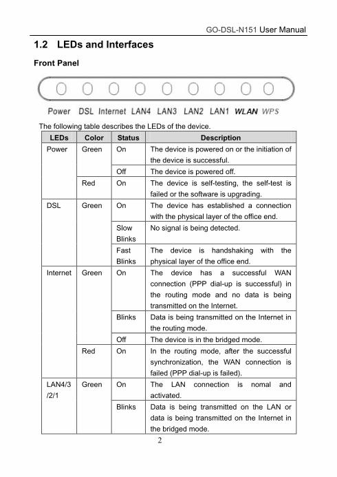
1.2 LEDs and Interfaces
Front Panel
The following table describes the LEDs of the device.
LEDs Color Status Description
Power Green On The device is powered on or the initiation of
the device is successful.
Off The device is powered off.
Red On The device is self-testing, the self-test is
failed or the software is upgrading.
DSL Green On The device has established a connection
with the physical layer of the office end.
Slow
Blinks
No signal is being detected.
Fast
Blinks
The device is handshaking with the
physical layer of the office end.
Internet Green On The device has a successful WAN
connection (PPP dial-up is successful) in
the routing mode and no data is being
transmitted on the Internet.
Blinks Data is being transmitted on the Internet in
the routing mode.
Off The device is in the bridged mode.
Red On In the routing mode, after the successful
synchronization, the WAN connection is
failed (PPP dial-up is failed).
LAN4/3
/2/1
Green On The LAN connection is nomal and
activated.
Blinks Data is being transmitted on the LAN or
data is being transmitted on the Internet in
the bridged mode.

GO-DSL-N151 User Manual
3
LEDs Color Status Description
Off The LAN connection of the device is failed.
WLAN Green On The device has successful WLAN
connection.
Blinks Data is being transmitted on WLAN.
Off The WLAN connection is failed.
WPS Green Off WPS is disabled.
Blinks WPS is enabled, and is waiting for client to
negotiate.
Rear Panel
The following table describes the interfaces of the device:
Items Description
ON/OFF Power switch for powering on/off the device.
Power Power interface for connecting to the power adapter.
WLAN Press the button gently and let go after 2 seconds to enable
WLAN function.
WPS Press the button and let go after 1 second to enable WPS
function.
Reset
Reset to the factory defaults. To reset to the factory
defaults, keep the device powered on and push a paper clip
in to the hole for over 3 seconds. Then release it, the
configuration is reset to the factory defaults.
LAN4/3/2/1 RJ-45 interface for connecting to the Ethernet interface of
PC or other Ethernet devices through the Ethernet cable.
DSL RJ-11 interface for connecting to the ADSL interface or a
splitter through the telephone cable.
GO-DSL-N151 User Manual
4
1.3 System Requirements
Recommended system requirements are as follows:
A 10/100 base-T Ethernet card is installed on your PC
A hub or Switch. (connected to several PCs through one of Ethernet
interfaces on the device)
Operating system: Windows 98 SE, Windows 2000, Windows ME,
Windows XP, Windows Vista, Windows 7
Internet Explorer V5.0 or higher, Netscape V4.0 or higher, or Firefox 1.5 or
higher
1.4 Features
The device supports the following features:
Various line modes
External PPPoE dial-up access
Internal PPPoE/PPPoA dial-up access
1483Bridged/1483Routed with dynamic ip or static ip
Multiple PVCs (the number of PVCs support is eight)
DHCP server/relay
Static route
Network Address Translation(NAT)
DMZ
Virtual Server
Universal plug and play (UPnP)
Dynamic Domain Name Server(DDNS)
One-level password and username
Network Time Protocol(NTP)
Firmware upgrading through Web, TFTP, or FTP
Resetting to the factory defaults through Reset button or Web
Diagnostic test
Web interface
Telnet CLI
IP/MAC/URL Filter
Application layer service
QOS
Port binding
GO-DSL-N151 User Manual
5
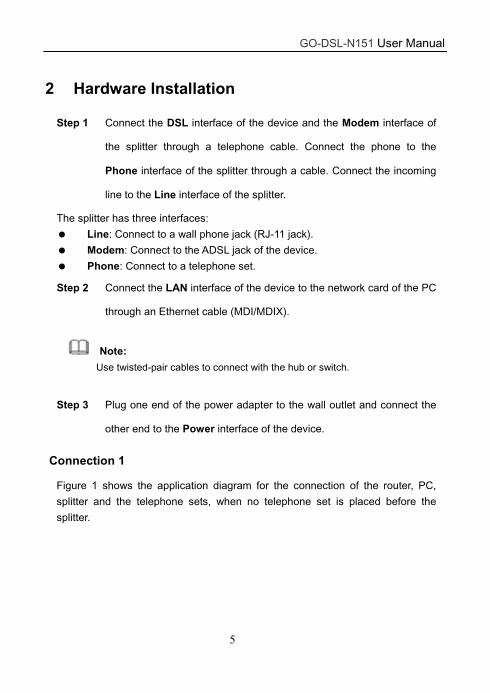
2 Hardware Installation
Step 1 Connect the DSL interface of the device and the Modem interface of
the splitter through a telephone cable. Connect the phone to the
Phone interface of the splitter through a cable. Connect the incoming
line to the Line interface of the splitter.
The splitter has three interfaces:
Line: Connect to a wall phone jack (RJ-11 jack).
Modem: Connect to the ADSL jack of the device.
Phone: Connect to a telephone set.
Step 2 Connect the LAN interface of the device to the network card of the PC
through an Ethernet cable (MDI/MDIX).
Note:
Use twisted-pair cables to connect with the hub or switch.
Step 3 Plug one end of the power adapter to the wall outlet and connect the
other end to the Power interface of the device.
Connection 1
Figure 1 shows the application diagram for the connection of the router, PC,
splitter and the telephone sets, when no telephone set is placed before the
splitter.

GO-DSL-N151 User Manual
6
Figure 1 Connection diagram (Without connecting telephone sets before the splitter)
Connection 2
Figure 2 shows the connection when the splitter is installed close to the router.
Figure 2 Connection diagram (Connecting a telephone set before the splitter)
GO-DSL-N151 User Manual
7
Note:
When connection 2 is used, the filter must be installed close to the telephone
cable. See Figure2. Do not use the splitter to replace the filter.
Installing a telephone directly before the splitter may lead to failure of
connection between the device and the central office or failure of Internet
access or slow connection speed. If you really need to add a telephone set
before the splitter, you must add a microfilter before a telephone set. Do not
connect several telephones before the splitter or connect several telephones
with the microfilter.

GO-DSL-N151 User Manual
8
3 About the Web Configuration
This chapter describes how to configure the router by using the Web-based
configuration utility.
3.1 Access the Router
The following is the detailed description of accessing the router for the first time.
Step 1 Open the Internet Explorer (IE) browser and enter http://192.168.1.1.
Step 2 In the Login page that is displayed, enter the username and password.
The username and password of the user are admin and admin.
When you log in, the page shown in the following figure appears. You can check,
configure and modify all the settings.
Note:
In the Web configuration page, the settings can be saved permanently.
3.2 Status
In the navigation bar, click Status. In the Status page that is displayed contains
Device Info, System Log and Statistics.
GO-DSL-N151 User Manual
9
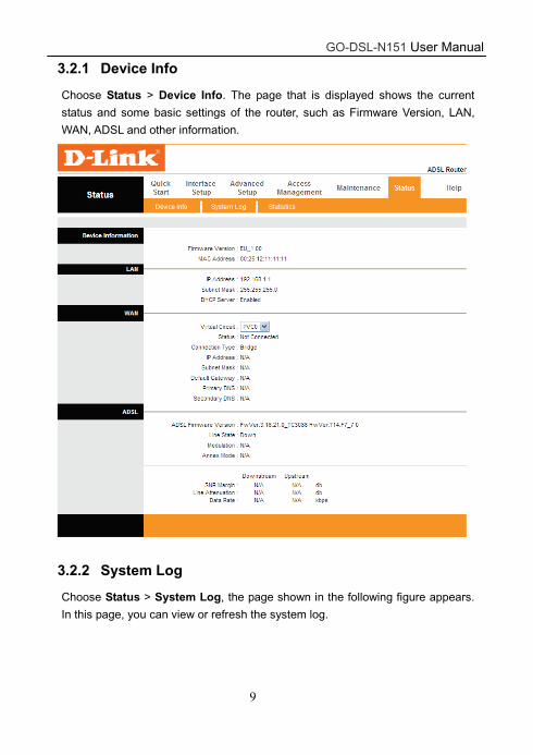
3.2.1 Device Info
Choose Status > Device Info. The page that is displayed shows the current
status and some basic settings of the router, such as Firmware Version, LAN,
WAN, ADSL and other information.
3.2.2 System Log
Choose Status > System Log, the page shown in the following figure appears.
In this page, you can view or refresh the system log.

GO-DSL-N151 User Manual
10
3.2.3 Statistics
Choose Status > Statistics. The Statistics page that is displayed contains
Ethernet Statistics, ADSL Statistics and WLAN Statistics.
3.2.3.1 Ethernet Statistics
In the Traffic Statistic page, click Ethernet and the page shown in the following
figure appears. In this page, you can view the statistics such as total Bytes,
Collision, Error Frames and CRC Errors.
GO-DSL-N151 User Manual
11
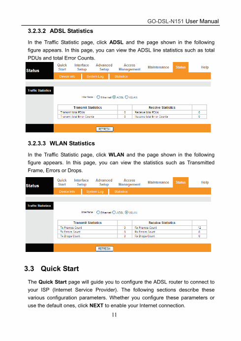
3.2.3.2 ADSL Statistics
In the Traffic Statistic page, click ADSL and the page shown in the following
figure appears. In this page, you can view the ADSL line statistics such as total
PDUs and total Error Counts.
3.2.3.3 WLAN Statistics
In the Traffic Statistic page, click WLAN and the page shown in the following
figure appears. In this page, you can view the statistics such as Transmitted
Frame, Errors or Drops.
3.3 Quick Start
The Quick Start page will guide you to configure the ADSL router to connect to
your ISP (Internet Service Provider). The following sections describe these
various configuration parameters. Whether you configure these parameters or
use the default ones, click NEXT to enable your Internet connection.
GO-DSL-N151 User Manual
12
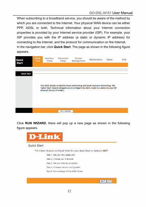
When subscribing to a broadband service, you should be aware of the method by
which you are connected to the Internet. Your physical WAN device can be either
PPP, ADSL or both. Technical information about your Internet connection
properties is provided by your Internet service provider (ISP). For example, your
ISP provides you with the IP address (a static or dynamic IP address) for
connecting to the Internet, and the protocol for communication on the Internet.
In the navigation bar, click Quick Start. The page as shown in the following figure
appears.
Click RUN WIZARD, there will pop up a new page as shown in the following
figure appears.

GO-DSL-N151 User Manual
13
Click NEXT, the page as shown in the following figure appears. Click EXIT, this
page will be closed.
In this page, enter a new password for the admin account. After finishing all quick
start settings, it will be saved and effect immediately.
Click NEXT, the page as shown in the following figure appears.
In this page, you can select a local time zone.
Click NEXT, the page as shown in the following figure appears.
GO-DSL-N151 User Manual
14
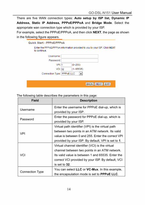
There are five WAN connection types: Auto setup by ISP list, Dynamic IP
Address, Static IP Address, PPPoE/PPPoA and Bridge Mode. Select the
appropriate wan connection type which is provided by your ISP.
For example, select the PPPoE/PPPoA, and then click NEXT, the page as shown
in the following figure appears.
The following table describes the parameters in this page:
Field Description
Username Enter the username for PPPoE dial-up, which is
provided by your ISP.
Password Enter the password for PPPoE dial-up, which is
provided by your ISP.
VPI
Virtual path identifier (VPI) is the virtual path
between two points in an ATM network. Its valid
value is between 0 and 255. Enter the correct VPI
provided by your ISP. By default, VPI is set to 1.
VCI
Virtual channel identifier (VCI) is the virtual
channel between two points in an ATM network.
Its valid value is between 1 and 65535. Enter the
correct VCI provided by your ISP. By default, VCI
is set to 32.
Connection Type You can select LLC or VC-Mux. In this example,
the encapsulation mode is set to PPPoE LLC.
GO-DSL-N151 User Manual
15
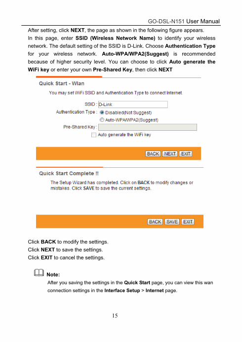
After setting, click NEXT, the page as shown in the following figure appears.
In this page, enter SSID (Wireless Network Name) to identify your wireless
network. The default setting of the SSID is D-Link. Choose Authentication Type
for your wireless network. Auto-WPA/WPA2(Suggest) is recommended
because of higher security level. You can choose to click Auto generate the
WiFi key or enter your own Pre-Shared Key, then click NEXT
Click BACK to modify the settings.
Click NEXT to save the settings.
Click EXIT to cancel the settings.
Note:
After you saving the settings in the Quick Start page, you can view this wan
connection settings in the Interface Setup > Internet page.
GO-DSL-N151 User Manual
16
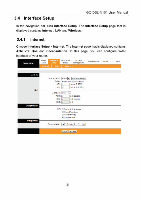
3.4 Interface Setup
In the navigation bar, click Interface Setup. The Interface Setup page that is
displayed contains Internet, LAN and Wireless.
3.4.1 Internet
Choose Interface Setup > Internet. The Internet page that is displayed contains
ATM VC, Qos and Encapsulation. In this page, you can configure WAN
interface of your router.
GO-DSL-N151 User Manual
17
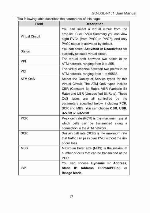
The following table describes the parameters of this page:
Field Description
Virtual Circuit
You can select a virtual circuit from the
drop-list. Click PVCs Summary you can view
eight PVCs (from PVC0 to PVC7), and only
PVC0 status is activated by default.
Status You can select Activated or Deactivated for
currently selected virtual circuit.
VPI The virtual path between two points in an
ATM network, ranging from 0 to 255.
VCI The virtual channel between two points in an
ATM network, ranging from 1 to 65535.
ATM QoS Select the Quality of Service types for this
Virtual Circuit. The ATM QoS types include
CBR (Constant Bit Rate), VBR (Variable Bit
Rate) and UBR (Unspecified Bit Rate). These
QoS types are all controlled by the
parameters specified below, including PCR,
SCR and MBS. You can choose CBR, UBR,
rt-VBR or nrt-VBR.
PCR Peak cell rate (PCR) is the maximum rate at
which cells can be transmitted along a
connection in the ATM network.
SCR Sustain cell rate (SCR) is the maximum rate
that traffic can pass over PVC without the risk
of cell loss.
MBS Maximum burst size (MBS) is the maximum
number of cells that can be transmitted at the
PCR.
ISP
You can choose Dynamic IP Address,
Static IP Address, PPPoA/PPPoE or
Bridge Mode.
GO-DSL-N151 User Manual
18
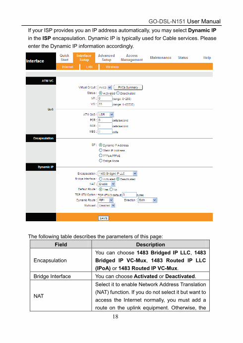
If your ISP provides you an IP address automatically, you may select Dynamic IP
in the ISP encapsulation. Dynamic IP is typically used for Cable services. Please
enter the Dynamic IP information accordingly.
The following table describes the parameters of this page:
Field Description
Encapsulation
You can choose 1483 Bridged IP LLC, 1483 Bridged IP VC-Mux, 1483 Routed IP LLC (IPoA) or 1483 Routed IP VC-Mux.
Bridge Interface You can choose Activated or Deactivated.
NAT
Select it to enable Network Address Translation
(NAT) function. If you do not select it but want to
access the Internet normally, you must add a
route on the uplink equipment. Otherwise, the
GO-DSL-N151 User Manual
19
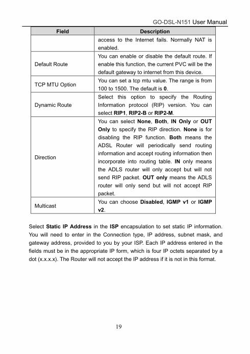
Field Description
access to the Internet fails. Normally NAT is
enabled.
Default Route
You can enable or disable the default route. If
enable this function, the current PVC will be the
default gateway to internet from this device.
TCP MTU Option You can set a tcp mtu value. The range is from
100 to 1500. The default is 0.
Dynamic Route
Select this option to specify the Routing
Information protocol (RIP) version. You can
select RIP1, RIP2-B or RIP2-M.
Direction
You can select None, Both, IN Only or OUT Only to specify the RIP direction. None is for
disabling the RIP function. Both means the
ADSL Router will periodically send routing
information and accept routing information then
incorporate into routing table. IN only means
the ADLS router will only accept but will not
send RIP packet. OUT only means the ADLS
router will only send but will not accept RIP
packet.
Multicast You can choose Disabled, IGMP v1 or IGMP v2.
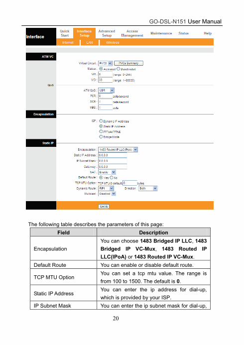
Select Static IP Address in the ISP encapsulation to set static IP information.
You will need to enter in the Connection type, IP address, subnet mask, and
gateway address, provided to you by your ISP. Each IP address entered in the
fields must be in the appropriate IP form, which is four IP octets separated by a
dot (x.x.x.x). The Router will not accept the IP address if it is not in this format.
GO-DSL-N151 User Manual
20
The following table describes the parameters of this page:
Field Description
Encapsulation
You can choose 1483 Bridged IP LLC, 1483
Bridged IP VC-Mux, 1483 Routed IP
LLC(IPoA) or 1483 Routed IP VC-Mux.
Default Route You can enable or disable default route.
TCP MTU Option You can set a tcp mtu value. The range is
from 100 to 1500. The default is 0.
Static IP Address You can enter the ip address for dial-up,
which is provided by your ISP.
IP Subnet Mask You can enter the ip subnet mask for dial-up,
GO-DSL-N151 User Manual
21
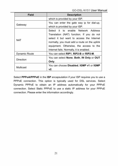
Field Description
which is provided by your ISP.
Gateway You can enter the gate way ip for dial-up,
which is provided by your ISP.
NAT
Select it to enable Network Address
Translation (NAT) function. If you do not
select it but want to access the Internet
normally, you must add a route on the uplink
equipment. Otherwise, the access to the
Internet fails. Normally, it is enabled.
Dynamic Route You can select RIP1, RIP2-B or RIP2-M.
Direction You can select None, Both, IN Only or OUT
Only.
Multicast You can choose Disabled, IGMP v1 or IGMP
v2.
Select PPPoA/PPPoE in the ISP encapsulation if your ISP requires you to use a
PPPoE connection. This option is typically used for DSL services. Select
Dynamic PPPoE to obtain an IP address automatically for your PPPoE
connection. Select Static PPPoE to use a static IP address for your PPPoE
connection. Please enter the information accordingly.

GO-DSL-N151 User Manual
22
GO-DSL-N151 User Manual
23
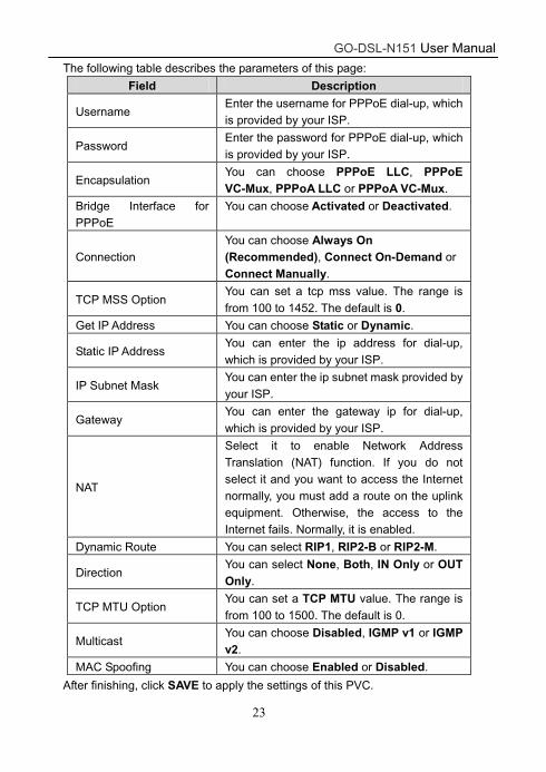
The following table describes the parameters of this page:
Field Description
Username Enter the username for PPPoE dial-up, which is provided by your ISP.
Password Enter the password for PPPoE dial-up, which is provided by your ISP.
Encapsulation You can choose PPPoE LLC, PPPoE VC-Mux, PPPoA LLC or PPPoA VC-Mux.
Bridge Interface for PPPoE
You can choose Activated or Deactivated.
Connection You can choose Always On (Recommended), Connect On-Demand or Connect Manually.
TCP MSS Option You can set a tcp mss value. The range is from 100 to 1452. The default is 0.
Get IP Address You can choose Static or Dynamic.
Static IP Address You can enter the ip address for dial-up, which is provided by your ISP.
IP Subnet Mask You can enter the ip subnet mask provided by your ISP.
Gateway You can enter the gateway ip for dial-up, which is provided by your ISP.
NAT
Select it to enable Network Address Translation (NAT) function. If you do not select it and you want to access the Internet normally, you must add a route on the uplink equipment. Otherwise, the access to the Internet fails. Normally, it is enabled.
Dynamic Route You can select RIP1, RIP2-B or RIP2-M.
Direction You can select None, Both, IN Only or OUT Only.
TCP MTU Option You can set a TCP MTU value. The range is from 100 to 1500. The default is 0.
Multicast You can choose Disabled, IGMP v1 or IGMP v2.
MAC Spoofing You can choose Enabled or Disabled.
After finishing, click SAVE to apply the settings of this PVC.

GO-DSL-N151 User Manual
24
3.4.2 LAN
Choose Interface Setup > LAN. The LAN page that is displayed contains
Router Local IP, DHCP Server and DNS. In this page, you can change IP
address of the router. The default IP address is 192.168.1.1, which is the private
IP address of the router.
The following table describes the parameters of this page:
Field Description
Main IP Address
Enter the IP address of LAN interface. It is
recommended to use an address from a block
reserved for private use. This address block is
192.168.1.1- 192.168.255.254.
Main Subnet Mask
Enter the subnet mask of LAN interface. The range
of subnet mask is from 255.255.0.0 to
255.255.255.254.
Alias IP Address You may enter the secondary IP Address.
GO-DSL-N151 User Manual
25
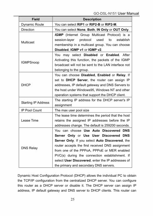
Field Description
Dynamic Route You can select RIP1 or RIP2-B or RIP2-M.
Direction You can select None, Both, IN Only or OUT Only.
Multicast
IGMP (Internet Group Multicast Protocol) is a
session-layer protocol used to establish
membership in a multicast group. You can choose
Disabled, IGMP v1 or IGMP v2.
IGMPSnoop
You may select Disabled or Enabled. After
Activating this function, the packets of the IGMP
broadcast will not be sent to the LAN interface not
belonging to the group.
DHCP
You can choose Disabled, Enabled or Relay. If
set to DHCP Server, the router can assign IP
addresses, IP default gateway and DNS Servers to
the host under Windows95, Windows NT and other
operation systems that support the DHCP client.
Starting IP Address The starting IP address for the DHCP server's IP
assignment
IP Pool Count The max user pool size
Lease Time
The lease time determines the period that the host
retains the assigned IP addresses before the IP
addresses change. The default is 259200 seconds.
DNS Relay
You can choose Use Auto Discovered DNS
Server Only or Use User Discovered DNS
Server Only. If you select Auto Discovered, the
router accepts the first received DNS assignment
from one of the PPPoA, PPPoE or MER enabled
PVC(s) during the connection establishment. If
select User Discovered, enter the IP addresses of
the primary and secondary DNS servers.
Dynamic Host Configuration Protocol (DHCP) allows the individual PC to obtain
the TCP/IP configuration from the centralized DHCP server. You can configure
this router as a DHCP server or disable it. The DHCP server can assign IP
address, IP default gateway and DNS server to DHCP clients. This router can
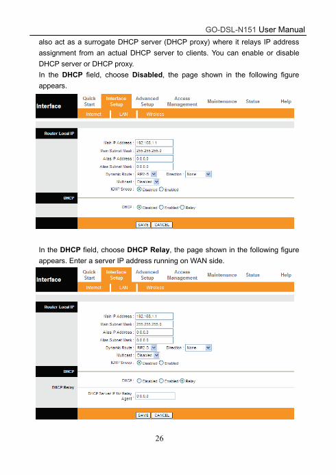
GO-DSL-N151 User Manual
26
also act as a surrogate DHCP server (DHCP proxy) where it relays IP address
assignment from an actual DHCP server to clients. You can enable or disable
DHCP server or DHCP proxy.
In the DHCP field, choose Disabled, the page shown in the following figure
appears.
In the DHCP field, choose DHCP Relay, the page shown in the following figure
appears. Enter a server IP address running on WAN side.
GO-DSL-N151 User Manual
27
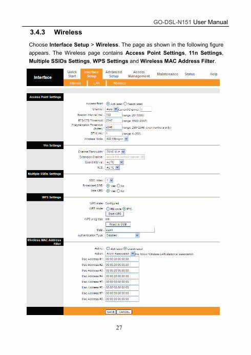
3.4.3 Wireless
Choose Interface Setup > Wireless. The page as shown in the following figure
appears. The Wireless page contains Access Point Settings, 11n Settings,
Multiple SSIDs Settings, WPS Settings and Wireless MAC Address Filter.

GO-DSL-N151 User Manual
28
The following table describes the parameters of this page:
Field Description
Access Point You may choose Activated or Deactivated.
Channel
Countries apply their own regulations to both the
allowable channels, allowed users and maximum
power levels within these frequency ranges. The
default is Auto.
Beacon Interval Beacon Interval range is from 20 to 1000.
RTS/CTS Threshold RTS/CTS Threshold range is from 1500 to 2347.
Fragmentation
Threshold
Fragmentation Threshold range are only even
numbers between 256 and 2346.
DTIM
DTIM range is from 1 to 255. A delivery traffic
indication message is a kind of traffic indication
message (TIM) which informs the clients of the
presence of buffered multicast/broadcast data on
the access point.
Wireless Mode
Comply with the IEEE 802.11b/g and IEEE802.11n
standards. You can select 802.11b, 802.11g,
802.11b+g, 802.11n, 802.11g+n or 802.11b+g+n.
Channel Bandwidth Supporting 20MHz/40MHz Dual Channel.
Extension Channel The fied displays the current extension channel is
above or below the current control channel.
Guard Interval You can set 800 nsec or AUTO.
MCS You can set an MCS index from 0 and 7, or select
AUTO.
SSID index Supporting only a root SSID to be modified
Broadcast SSID
Select whether the router broadcasts SSID or not.
You can select Yes or No.
Select Yes, and the wireless client searches
the router through broadcasting SSID.
Select No to hide SSID, and the wireless
client can not search the SSID.
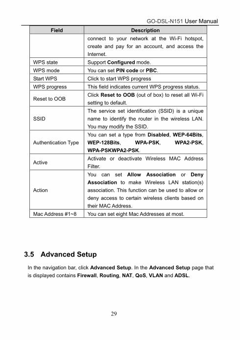
Use WPS WPS technology allows new customers without a
previously-established account to securely
GO-DSL-N151 User Manual
29
Field Description
connect to your network at the Wi-Fi hotspot,
create and pay for an account, and access the
Internet.
WPS state Support Configured mode.
WPS mode You can set PIN code or PBC.
Start WPS Click to start WPS progress
WPS progress This field indicates current WPS progress status.
Reset to OOB Click Reset to OOB (out of box) to reset all Wi-Fi
setting to default.
SSID
The service set identification (SSID) is a unique
name to identify the router in the wireless LAN.
You may modify the SSID.
Authentication Type
You can set a type from Disabled, WEP-64Bits,
WEP-128Bits, WPA-PSK, WPA2-PSK,
WPA-PSKWPA2-PSK.
Active Activate or deactivate Wireless MAC Address
Filter.
Action
You can set Allow Association or Deny
Association to make Wireless LAN station(s)
association. This function can be used to allow or
deny access to certain wireless clients based on
their MAC Address.
Mac Address #1~8 You can set eight Mac Addresses at most.
3.5 Advanced Setup
In the navigation bar, click Advanced Setup. In the Advanced Setup page that
is displayed contains Firewall, Routing, NAT, QoS, VLAN and ADSL.
GO-DSL-N151 User Manual
30
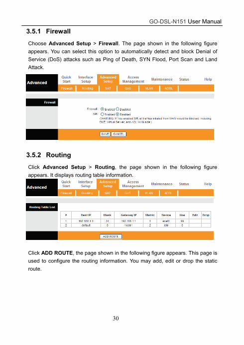
3.5.1 Firewall
Choose Advanced Setup > Firewall. The page shown in the following figure
appears. You can select this option to automatically detect and block Denial of
Service (DoS) attacks such as Ping of Death, SYN Flood, Port Scan and Land
Attack.
3.5.2 Routing
Click Advanced Setup > Routing, the page shown in the following figure
appears. It displays routing table information.
Click ADD ROUTE, the page shown in the following figure appears. This page is
used to configure the routing information. You may add, edit or drop the static
route.
GO-DSL-N151 User Manual
31
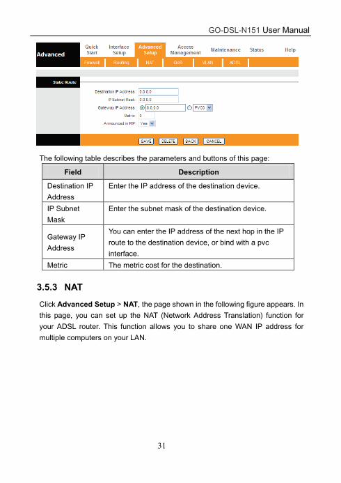
The following table describes the parameters and buttons of this page:
Field Description
Destination IP
Address
Enter the IP address of the destination device.
IP Subnet
Mask
Enter the subnet mask of the destination device.
Gateway IP
Address
You can enter the IP address of the next hop in the IP
route to the destination device, or bind with a pvc
interface.
Metric The metric cost for the destination.
3.5.3 NAT
Click Advanced Setup > NAT, the page shown in the following figure appears. In
this page, you can set up the NAT (Network Address Translation) function for
your ADSL router. This function allows you to share one WAN IP address for
multiple computers on your LAN.

GO-DSL-N151 User Manual
32
The following table describes the parameters and buttons of this page:
Field Description
Virtual Circuit Choose a Virtual Circuit Index to set up for the NAT
function.
NAT Status
This field shows the current NAT status for the current
VC. The status is activated or deactivated, depending
on the WAN connection's NAT is enable or disabled.
Demilitarized Zone (DMZ) is used to provide Internet services without sacrificing
unauthorized access to its local private network. Typically, the DMZ host contains
devices accessible to Internet traffic, such as web (HTTP) servers, FTP servers,
SMTP (e-mail) servers and DNS servers.
In the NAT page, select the number of IPs as Single and click DMZ, and the
page shown in the following figure appears.
The following table describes the parameters of this page:
GO-DSL-N151 User Manual
33
Field Description
DMZ Select Enable to enable this function.
DMZ Host IP
Address
Enter the specified IP Address for DMZ host on the
LAN side.
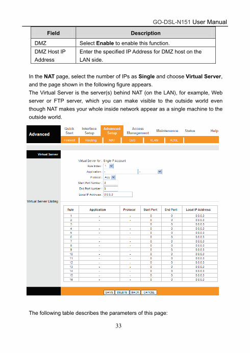
In the NAT page, select the number of IPs as Single and choose Virtual Server,
and the page shown in the following figure appears.
The Virtual Server is the server(s) behind NAT (on the LAN), for example, Web
server or FTP server, which you can make visible to the outside world even
though NAT makes your whole inside network appear as a single machine to the
outside world.
The following table describes the parameters of this page:
GO-DSL-N151 User Manual
34
Field Description
Rule Index
The Virtual server rule index for this VC. You can
specify 10 rules in maximum. All the VCs with single IP
will use the same Virtual Server rules.
Application Select an application type for this VC.
Protocol Select a protocl type for this VC
Start/End Port
Number
Enter the specific Start and End Port numbers you want
to forward. If it is one port only, you can enter the End
port number the same as Start port number. For
example, if you want to set the FTP Virtual server, you
can set both the start and end port number as 21.
Local IP
Address
Enter the IP Address for the Virtual Server in LAN side.
Rule
The Virtual server rule index for this VC. You can
specify 10 rules in maximum. All the VCs with single IP
will use the same Virtual Server rules.
In the NAT page, select the number of IPs as Multiple and choose IP Address
Mapping (for Multiple IP Service), and the page shown in the following figure
appears.

GO-DSL-N151 User Manual
35
The following table describes the parameters of this page:
Field Description
Rule Index
The Virtual server rule index for this VC. You can
specify 10 rules in maximum. All the VCs with single IP
will use the same Virtual Server rules.
Rule Type
There are four types of One-to-One, Many-to-One,
Many-to-Many Overload and Many-to-Many
No-overload.
Local Start/ End IP
Enter the local IP Address you plan to mapped to. Local
Start IP is the starting local IP address and Local End
IP is the ending local IP address. If the rule is for all
local IPs, then the Start IP is 0.0.0.0 and the End IP is
255.255.255.255.
Public Start/ End IP
Enter the public IP Address you want to do NAT. Public
Start IP is the starting public IP address and Public End
IP is the ending public IP address. If you have a
dynamic IP, enter 0.0.0.0 as the Public Start IP.
GO-DSL-N151 User Manual
36
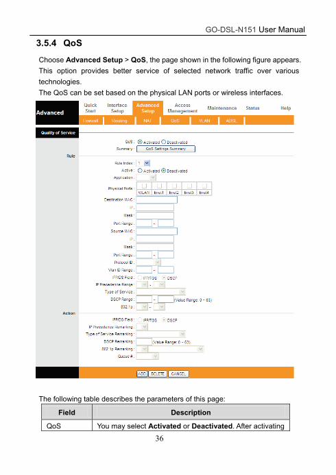
3.5.4 QoS
Choose Advanced Setup > QoS, the page shown in the following figure appears.
This option provides better service of selected network traffic over various
technologies.
The QoS can be set based on the physical LAN ports or wireless interfaces.
The following table describes the parameters of this page:
Field Description
QoS You may select Activated or Deactivated. After activating
GO-DSL-N151 User Manual
37
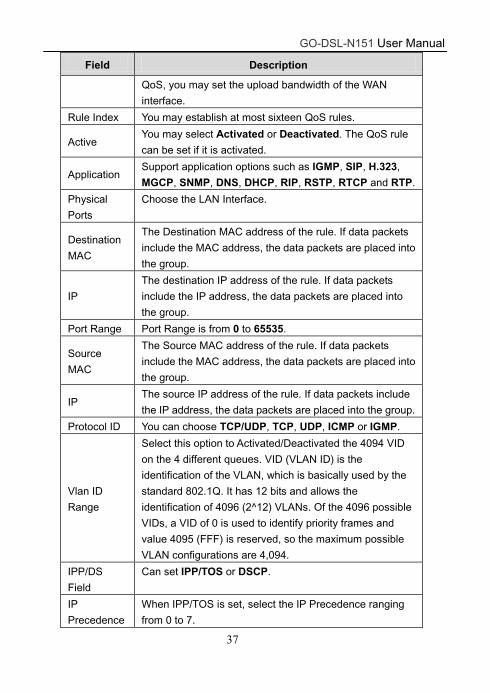
Field Description
QoS, you may set the upload bandwidth of the WAN
interface.
Rule Index You may establish at most sixteen QoS rules.
Active You may select Activated or Deactivated. The QoS rule
can be set if it is activated.
Application Support application options such as IGMP, SIP, H.323,
MGCP, SNMP, DNS, DHCP, RIP, RSTP, RTCP and RTP.
Physical
Ports
Choose the LAN Interface.
Destination
MAC
The Destination MAC address of the rule. If data packets
include the MAC address, the data packets are placed into
the group.
IP
The destination IP address of the rule. If data packets
include the IP address, the data packets are placed into
the group.
Port Range Port Range is from 0 to 65535.
Source
MAC
The Source MAC address of the rule. If data packets
include the MAC address, the data packets are placed into
the group.
IP The source IP address of the rule. If data packets include
the IP address, the data packets are placed into the group.
Protocol ID You can choose TCP/UDP, TCP, UDP, ICMP or IGMP.
Vlan ID
Range
Select this option to Activated/Deactivated the 4094 VID
on the 4 different queues. VID (VLAN ID) is the
identification of the VLAN, which is basically used by the
standard 802.1Q. It has 12 bits and allows the
identification of 4096 (2^12) VLANs. Of the 4096 possible
VIDs, a VID of 0 is used to identify priority frames and
value 4095 (FFF) is reserved, so the maximum possible
VLAN configurations are 4,094.
IPP/DS
Field
Can set IPP/TOS or DSCP.
IP
Precedence
When IPP/TOS is set, select the IP Precedence ranging
from 0 to 7.
GO-DSL-N151 User Manual
38
Field Description
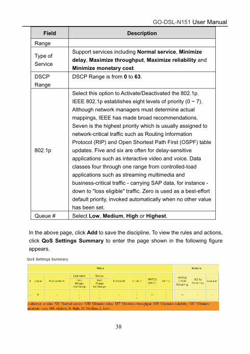
Range
Type of
Service
Support services including Normal service, Minimize
delay, Maximize throughput, Maximize reliability and
Minimize monetary cost.
DSCP
Range
DSCP Range is from 0 to 63.
802.1p
Select this option to Activate/Deactivated the 802.1p.
IEEE 802.1p establishes eight levels of priority (0 ~ 7).
Although network managers must determine actual
mappings, IEEE has made broad recommendations.
Seven is the highest priority which is usually assigned to
network-critical traffic such as Routing Information
Protocol (RIP) and Open Shortest Path First (OSPF) table
updates. Five and six are often for delay-sensitive
applications such as interactive video and voice. Data
classes four through one range from controlled-load
applications such as streaming multimedia and
business-critical traffic - carrying SAP data, for instance -
down to "loss eligible" traffic. Zero is used as a best-effort
default priority, invoked automatically when no other value
has been set.
Queue # Select Low, Medium, High or Highest.
In the above page, click Add to save the discipline. To view the rules and actions,
click QoS Settings Summary to enter the page shown in the following figure
appears.
GO-DSL-N151 User Manual
39
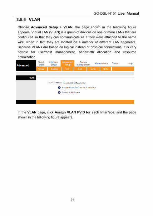
3.5.5 VLAN
Choose Advanced Setup > VLAN, the page shown in the following figure
appears. Virtual LAN (VLAN) is a group of devices on one or more LANs that are
configured so that they can communicate as if they were attached to the same
wire, when in fact they are located on a number of different LAN segments.
Because VLANs are based on logical instead of physical connections, it is very
flexible for user/host management, bandwidth allocation and resource
optimization.
In the VLAN page, click Assign VLAN PVID for each Interface, and the page
shown in the following figure appears.

GO-DSL-N151 User Manual
40
The following table describes the parameters of this page:
Field Description
PVID
Each physical port has a default VID called PVID (Port
VID). PVID is assigned to untagged frames or priority
tagged frames (frames with null (0) VID) received on this
port.
ATM VC # Assign the PVID to ATM VCs.
Ethernet
Port #
Assign the PVID to Ethernet Ports.
Wirelss LAN Assign the PVID to Wireless LAN.
Next Click it to go the the VLAN Group Setting page.
In the VLAN page, click Define VLAN Group, and the page shown in the
following figure appears.

GO-DSL-N151 User Manual
41
The following table describes the parameters of this page:
Field Description
VLAN Index Define the VLAN Group ID (1 to 8).
Active Choose to active or deactive the VLAN group.
VLAN ID Input a VLAN ID for the Group.
ATM VCs Select what ATM VCs (0 to 7) will join the VLAN group.
Also choose whether it will be tagged or untagged.
Ethernet Select what Ethernet ports (1 to 4) will join the VLAN
group. Also Choose whether it will be tagged or untagged.
Wireless
LAN
Choose to assign the Wirless LAN to the VLAN group.
Save Click it to save the settings.
Delete Click it to delete the current group setting.
Cancel Cancel the current group setting.
GO-DSL-N151 User Manual
42
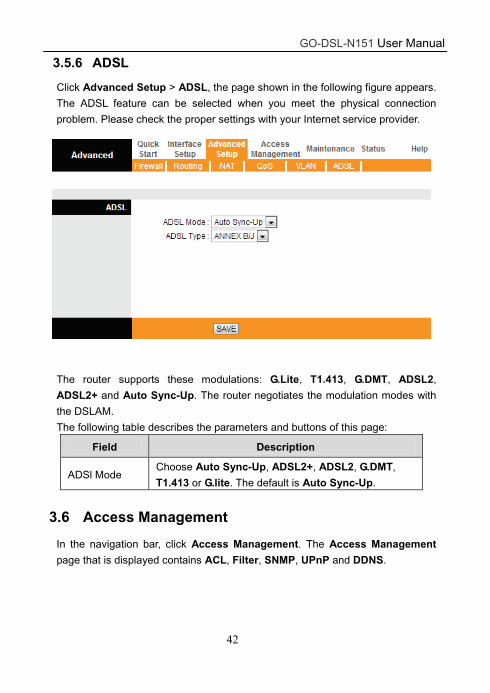
3.5.6 ADSL
Click Advanced Setup > ADSL, the page shown in the following figure appears.
The ADSL feature can be selected when you meet the physical connection
problem. Please check the proper settings with your Internet service provider.
The router supports these modulations: G.Lite, T1.413, G.DMT, ADSL2,
ADSL2+ and Auto Sync-Up. The router negotiates the modulation modes with
the DSLAM.
The following table describes the parameters and buttons of this page:
Field Description
ADSl Mode Choose Auto Sync-Up, ADSL2+, ADSL2, G.DMT,
T1.413 or G.lite. The default is Auto Sync-Up.
3.6 Access Management
In the navigation bar, click Access Management. The Access Management
page that is displayed contains ACL, Filter, SNMP, UPnP and DDNS.

GO-DSL-N151 User Manual
43
3.6.1 ACL
Choose Access Management > ACL, and the page shown in the following
figure appears. The user may remotely access the ADSL Router once setting his
IP as a Secure IP Address through selected applications. With the default IP
0.0.0.0, any client would be allowed to remotely access the ADSL Router.
The following table describes the parameters and buttons of this page:
Field Description
ACL Rule Index You can establish sixteen ACL rules at most.
Active Click to enable or disable the rule.
Secure IP
Address
The rule is valid if the IP is in this range.
Application Support Web, FTP, Telnet, SNMP, Ping and ALL.
Interface Support WAN, LAN and Both.
Access control
Listing
Only the devices whose MAC addresses are listed in
the Access Control Listing can access the router.
3.6.2 Filter
Choose Access Management > Filter, and the page shown in the following
figure appears. Select IP/MAC Filter type. The user can set IP/MAC Filter,
Application Filter and URL Filter.
GO-DSL-N151 User Manual
44
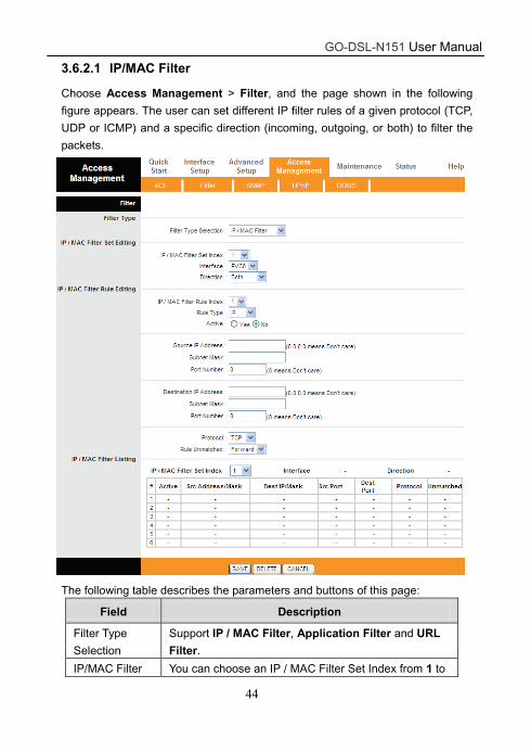
3.6.2.1 IP/MAC Filter
Choose Access Management > Filter, and the page shown in the following
figure appears. The user can set different IP filter rules of a given protocol (TCP,
UDP or ICMP) and a specific direction (incoming, outgoing, or both) to filter the
packets.
The following table describes the parameters and buttons of this page:
Field Description
Filter Type
Selection
Support IP / MAC Filter, Application Filter and URL
Filter.
IP/MAC Filter You can choose an IP / MAC Filter Set Index from 1 to
GO-DSL-N151 User Manual
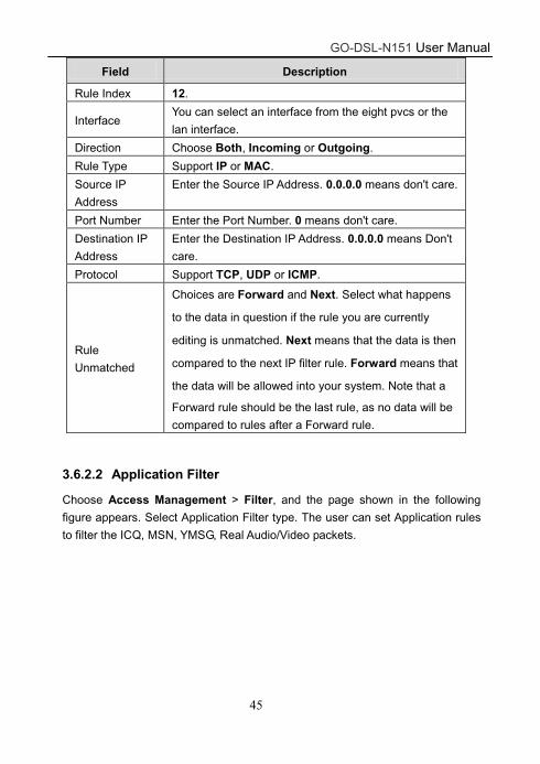
45
Field Description
Rule Index 12.
Interface You can select an interface from the eight pvcs or the
lan interface.
Direction Choose Both, Incoming or Outgoing.
Rule Type Support IP or MAC.
Source IP
Address
Enter the Source IP Address. 0.0.0.0 means don't care.
Port Number Enter the Port Number. 0 means don't care.
Destination IP
Address
Enter the Destination IP Address. 0.0.0.0 means Don't
care.
Protocol Support TCP, UDP or ICMP.
Rule
Unmatched
Choices are Forward and Next. Select what happens
to the data in question if the rule you are currently
editing is unmatched. Next means that the data is then
compared to the next IP filter rule. Forward means that
the data will be allowed into your system. Note that a
Forward rule should be the last rule, as no data will be
compared to rules after a Forward rule.
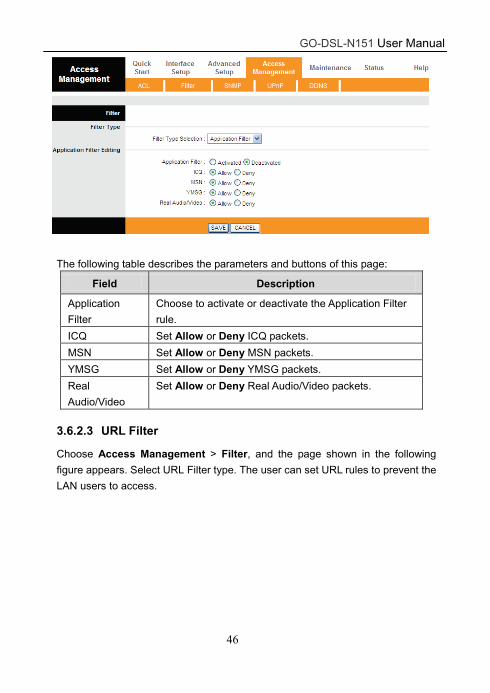
3.6.2.2 Application Filter
Choose Access Management > Filter, and the page shown in the following
figure appears. Select Application Filter type. The user can set Application rules
to filter the ICQ, MSN, YMSG, Real Audio/Video packets.
GO-DSL-N151 User Manual
46
The following table describes the parameters and buttons of this page:
Field Description
Application
Filter
Choose to activate or deactivate the Application Filter
rule.
ICQ Set Allow or Deny ICQ packets.
MSN Set Allow or Deny MSN packets.
YMSG Set Allow or Deny YMSG packets.
Real
Audio/Video
Set Allow or Deny Real Audio/Video packets.
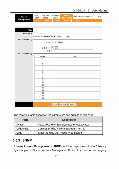
3.6.2.3 URL Filter
Choose Access Management > Filter, and the page shown in the following
figure appears. Select URL Filter type. The user can set URL rules to prevent the
LAN users to access.
GO-DSL-N151 User Manual
47
The following table describes the parameters and buttons of this page:
Field Description
Active Make URL Filter rule activated or deactivated.
URL Index Can set an URL Filter Index from 1 to 16.
URL Enter the URL that needs to be filtered.
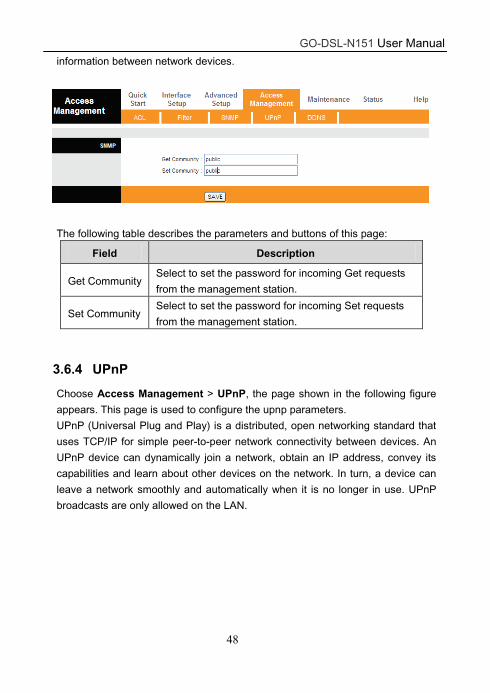
3.6.3 SNMP
Choose Access Management > SNMP, and the page shown in the following
figure appears. Simple Network Management Protocol is used for exchanging
GO-DSL-N151 User Manual
48
information between network devices.
The following table describes the parameters and buttons of this page:
Field Description
Get Community Select to set the password for incoming Get requests
from the management station.
Set Community Select to set the password for incoming Set requests
from the management station.
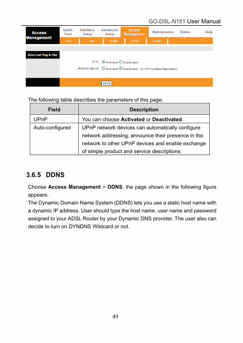
3.6.4 UPnP
Choose Access Management > UPnP, the page shown in the following figure
appears. This page is used to configure the upnp parameters.
UPnP (Universal Plug and Play) is a distributed, open networking standard that
uses TCP/IP for simple peer-to-peer network connectivity between devices. An
UPnP device can dynamically join a network, obtain an IP address, convey its
capabilities and learn about other devices on the network. In turn, a device can
leave a network smoothly and automatically when it is no longer in use. UPnP
broadcasts are only allowed on the LAN.
GO-DSL-N151 User Manual
49
The following table describes the parameters of this page:
Field Description
UPnP You can choose Activated or Deactivated.
Auto-configured UPnP network devices can automatically configure
network addressing, announce their presence in the
network to other UPnP devices and enable exchange
of simple product and service descriptions.
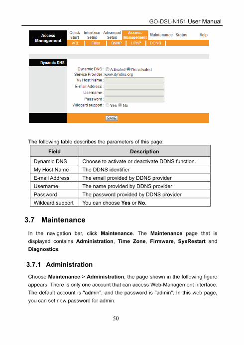
3.6.5 DDNS
Choose Access Management > DDNS, the page shown in the following figure
appears.
The Dynamic Domain Name System (DDNS) lets you use a static host name with
a dynamic IP address. User should type the host name, user name and password
assigned to your ADSL Router by your Dynamic DNS provider. The user also can
decide to turn on DYNDNS Wildcard or not.
GO-DSL-N151 User Manual
50
The following table describes the parameters of this page:
Field Description
Dynamic DNS Choose to activate or deactivate DDNS function.
My Host Name The DDNS identifier
E-mail Address The email provided by DDNS provider
Username The name provided by DDNS provider
Password The password provided by DDNS provider
Wildcard support You can choose Yes or No.
3.7 Maintenance
In the navigation bar, click Maintenance. The Maintenance page that is
displayed contains Administration, Time Zone, Firmware, SysRestart and
Diagnostics.
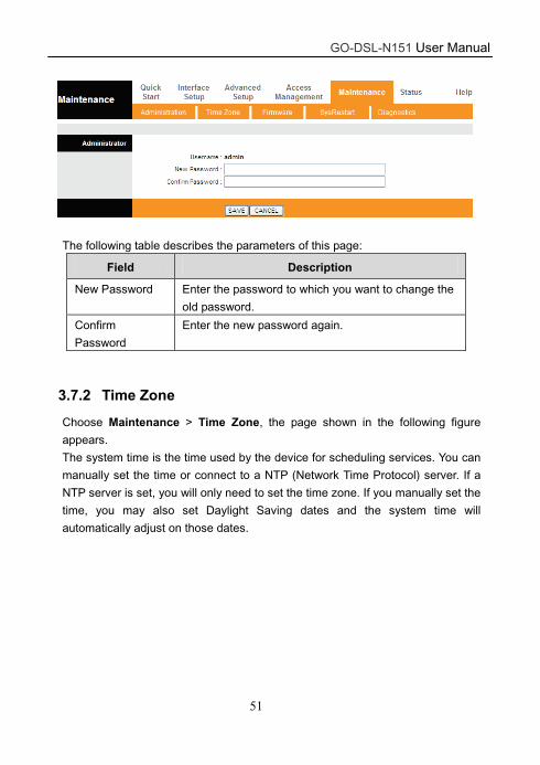
3.7.1 Administration
Choose Maintenance > Administration, the page shown in the following figure
appears. There is only one account that can access Web-Management interface.
The default account is "admin", and the password is "admin". In this web page,
you can set new password for admin.
GO-DSL-N151 User Manual
51
The following table describes the parameters of this page:
Field Description
New Password Enter the password to which you want to change the
old password.
Confirm
Password
Enter the new password again.
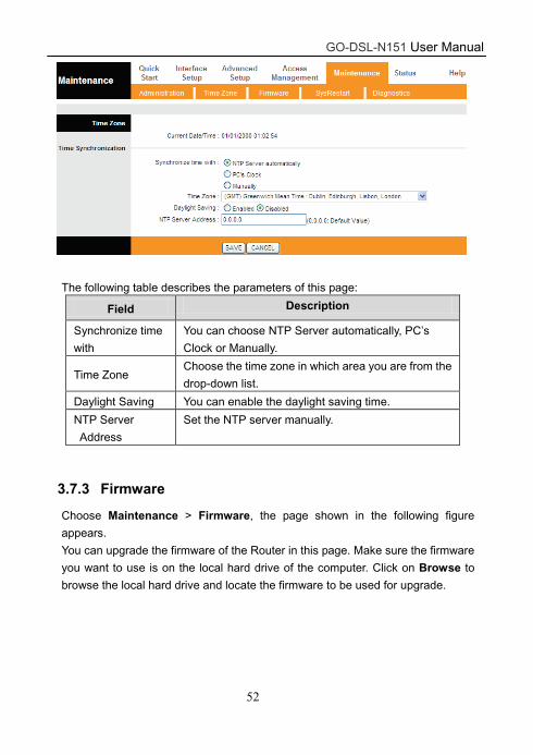
3.7.2 Time Zone
Choose Maintenance > Time Zone, the page shown in the following figure
appears.
The system time is the time used by the device for scheduling services. You can
manually set the time or connect to a NTP (Network Time Protocol) server. If a
NTP server is set, you will only need to set the time zone. If you manually set the
time, you may also set Daylight Saving dates and the system time will
automatically adjust on those dates.
GO-DSL-N151 User Manual
52
The following table describes the parameters of this page:
Field Description
Synchronize time
with
You can choose NTP Server automatically, PC’s
Clock or Manually.
Time Zone Choose the time zone in which area you are from the
drop-down list.
Daylight Saving You can enable the daylight saving time.
NTP Server
Address
Set the NTP server manually.
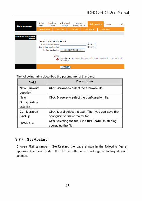
3.7.3 Firmware
Choose Maintenance > Firmware, the page shown in the following figure
appears.
You can upgrade the firmware of the Router in this page. Make sure the firmware
you want to use is on the local hard drive of the computer. Click on Browse to
browse the local hard drive and locate the firmware to be used for upgrade.
GO-DSL-N151 User Manual
53
The following table describes the parameters of this page:
Field Description
New Firmware
Location
Click Browse to select the firmware file.
New
Configuration
Location
Click Browse to select the configuration file.
Configuration
Backup
Click it, and select the path. Then you can save the
configuration file of the router.
UPGRADE After selecting the file, click UPGRADE to starting
upgrading the file.
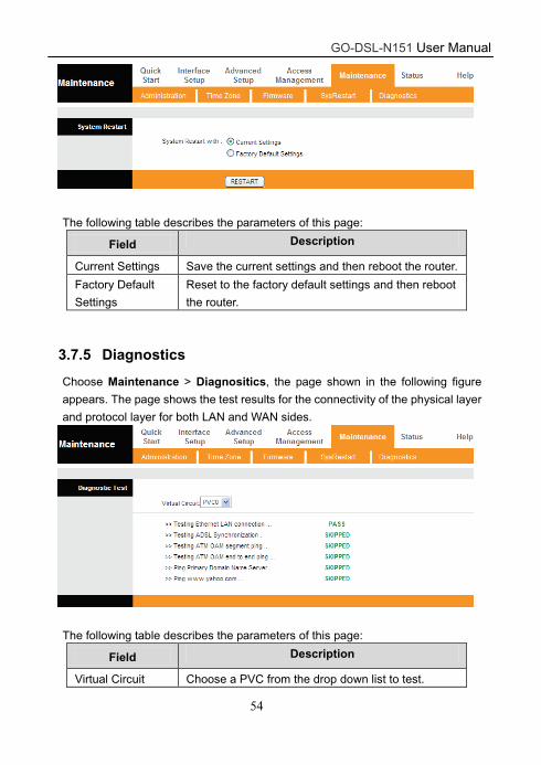
3.7.4 SysRestart
Choose Maintenance > SysRestart, the page shown in the following figure
appears. User can restart the device with current settings or factory default
settings.
GO-DSL-N151 User Manual
54
The following table describes the parameters of this page:
Field Description
Current Settings Save the current settings and then reboot the router.
Factory Default
Settings
Reset to the factory default settings and then reboot
the router.
3.7.5 Diagnostics
Choose Maintenance > Diagnositics, the page shown in the following figure
appears. The page shows the test results for the connectivity of the physical layer
and protocol layer for both LAN and WAN sides.
The following table describes the parameters of this page:
Field Description
Virtual Circuit Choose a PVC from the drop down list to test.

GO-DSL-N151 User Manual
55
3.8 Help
In the navigation bar, click Help. The Help page that is displayed contains Quick
Start, Interface Setup, Advanced Setup, Access Management, Maintenance
and Status. You can get information on detailed functions and parameter
configuration of the device.
3.8.1 Quick Start
Choose Help > Quick Start, the page shown in the following figure appears.
Quick Start
The Quick Start Wizard is a useful and easy utility to help setup the device to quickly connect
to your ISP (Internet Service Provider) with only a few steps required. It will guide you step by
step to configure the password, time zone, and WAN settings of your device. The Quick Start
Wizard is a helpful guide for first time users to the device.
GO-DSL-N151 User Manual
56
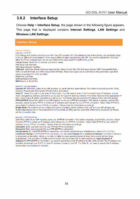
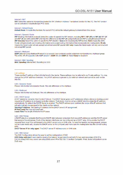
3.8.2 Interface Setup
Choose Help > Interface Setup, the page shown in the following figure appears.
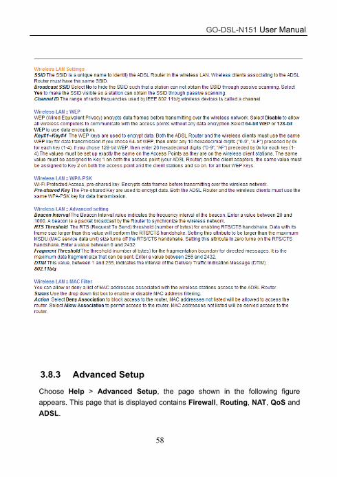
This page that is displayed contains Internet Settings, LAN Settings and
Wireless LAN Settings.
GO-DSL-N151 User Manual
57
GO-DSL-N151 User Manual
58
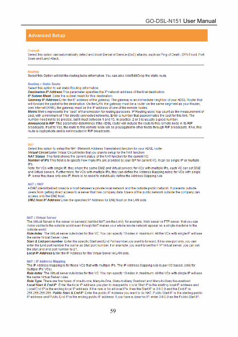
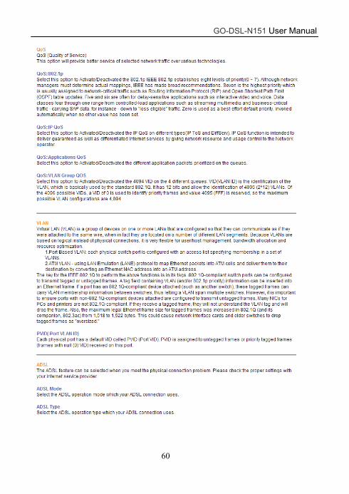
3.8.3 Advanced Setup
Choose Help > Advanced Setup, the page shown in the following figure
appears. This page that is displayed contains Firewall, Routing, NAT, QoS and
ADSL.
GO-DSL-N151 User Manual
59
GO-DSL-N151 User Manual
60
GO-DSL-N151 User Manual
61
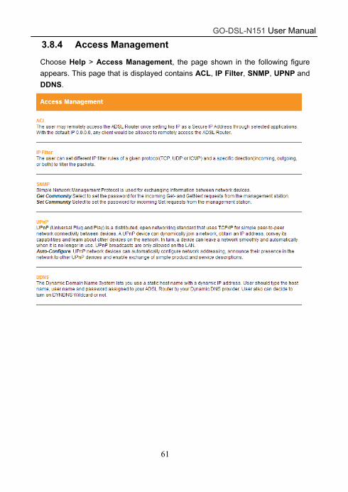
3.8.4 Access Management
Choose Help > Access Management, the page shown in the following figure
appears. This page that is displayed contains ACL, IP Filter, SNMP, UPNP and
DDNS.
GO-DSL-N151 User Manual
62
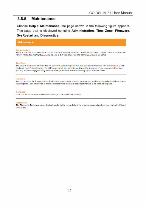
3.8.5 Maintenance
Choose Help > Maintenance, the page shown in the following figure appears.
This page that is displayed contains Administration, Time Zone, Firmware,
SysRestart and Diagnostics.
GO-DSL-N151 User Manual
63
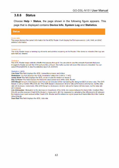
3.8.6 Status
Choose Help > Status, the page shown in the following figure appears. This
page that is displayed contains Device Info, System Log and Statistics.