ds457 fixed mount imager integration guide
TRANSCRIPT

DS457 FIXED MOUNT IMAGERINTEGRATION GUIDE


DS457 FIXED MOUNT IMAGERINTEGRATION GUIDE
72E-144361-06EN Revision A
March 2021

ii DS457 Fixed Mount Imager Integration Guide
No part of this publication may be reproduced or used in any form, or by any electrical or mechanical means, without permission in writing from Zebra. This includes electronic or mechanical means, such as photocopying, recording, or information storage and retrieval systems. The material in this manual is subject to change without notice.
The software is provided strictly on an “as is” basis. All software, including firmware, furnished to the user is on a licensed basis. Zebra grants to the user a non-transferable and non-exclusive license to use each software or firmware program delivered hereunder (licensed program). Except as noted below, such license may not be assigned, sublicensed, or otherwise transferred by the user without prior written consent of Zebra. No right to copy a licensed program in whole or in part is granted, except as permitted under copyright law. The user shall not modify, merge, or incorporate any form or portion of a licensed program with other program material, create a derivative work from a licensed program, or use a licensed program in a network without written permission from Zebra. The user agrees to maintain Zebra’s copyright notice on the licensed programs delivered hereunder, and to include the same on any authorized copies it makes, in whole or in part. The user agrees not to decompile, disassemble, decode, or reverse engineer any licensed program delivered to the user or any portion thereof.
Zebra reserves the right to make changes to any software or product to improve reliability, function, or design.
Zebra does not assume any product liability arising out of, or in connection with, the application or use of any product, circuit, or application described herein.
No license is granted, either expressly or by implication, estoppel, or otherwise under any Zebra Technologies Corporation intellectual property rights. An implied license only exists for equipment, circuits, and subsystems contained in Zebra products.
This media, or Zebra Product, may include Zebra Software, Commercial Third Party Software, and Publicly Available Software.
The Zebra Software that may be included on this media, or included in the Zebra Product, is Copyright (c) by Zebra Technologies Corporation, and its use is subject to the licenses, terms and conditions of the agreement in force between the purchaser of the Zebra Product.
The Commercial Third Party Software that may be included on this media, or included in the Zebra Product, is subject to the licenses, terms and conditions of the agreement in force between the purchaser of the Zebra Product and Zebra Technologies Corporation, unless a separate Commercial Third Party Software License is included, in which case, your use of the Commercial Third Party Software will then be governed by the separate Commercial Third Party License.
The Publicly Available Software that may be included on this media, or in the Zebra Product, is listed below. The use of the listed Publicly Available Software is subject to the licenses, terms and conditions of the agreement in force between the purchaser of the Zebra Product and Zebra Technologies Corporation, as well as, the terms and conditions of the license of each Publicly Available Software package. Copies of the licenses for the listed Publicly Available Software, as well as, all attributions, acknowledgements, and software information details, are included below. Zebra is required to reproduce the software licenses, acknowledgments and copyright notices as provided by the Authors and Owners, thus, all such information is provided in its native language form, without modification or translation.
The Publicly Available Software in the list below is limited to the Publicly Available Software included by Zebra. The Publicly Available Software included by Commercial Third Party Software or Products, that is used in the Zebra Product, are disclosed in the Commerical Third Party Licenses, or via the respective Commercial Third Party Publicly Available Software Legal Notices.
Publicly available software list:Name: Regular Expression EvaluatorVersion: 8.3 Description: Compiles and executes regular expressionsSoftware Site: http://www.freebsd.org/cgi/cvsweb.cgi/src/lib/libc/regex/Source Code: No Source Distribution Obligations. Zebra will not provide nor distribute the Source Code for the
Regular Expression Evaluator.License: BSD Style License
© 1992 Henry Spencer.
© 1992, 1993 The Regents of the University of California. All rights reserved.
This code is derived from software contributed to Berkeley by Henry Spencer of the University of Toronto. Redistribution and use in source and binary forms, with or without modification, are permitted provided that the following conditions are met:
1. Redistributions of source code must retain the above copyright notice, this list of conditions and the following disclaimer.
2. Redistributions in binary form must reproduce the above copyright notice, this list of conditions and the following disclaimer in thedocumentation and/or other materials provided with the distribution.
3. All advertising materials mentioning features or use of this software must display the following acknowledgement:
This product includes software developed by the University of California, Berkeley and its contributors.
4. Neither the name of the University nor the names of its contributors may be used to endorse or promote products derived from thissoftware without specific prior written permission.
THIS SOFTWARE IS PROVIDED BY THE REGENTS AND CONTRIBUTORS ``AS IS'' AND ANY EXPRESS OR IMPLIED WARRANTIES, INCLUDING, BUT NOT LIMITED TO, THE IMPLIED WARRANTIES OF MERCHANTABILITY AND FITNESS FOR A

iii
PARTICULAR PURPOSE ARE DISCLAIMED. IN NO EVENT SHALL THE REGENTS OR CONTRIBUTORS BE LIABLE FOR ANY DIRECT, INDIRECT, INCIDENTAL, SPECIAL, EXEMPLARY, OR CONSEQUENTIAL DAMAGES (INCLUDING, BUT NOT LIMITED TO, PROCUREMENT OF SUBSTITUTE GOODS OR SERVICES; LOSS OF USE, DATA, OR PROFITS; OR BUSINESS INTERRUPTION) HOWEVER CAUSED AND ON ANY THEORY OF LIABILITY, WHETHER IN CONTRACT, STRICT LIABILITY, OR TORT (INCLUDING NEGLIGENCE OR OTHERWISE) ARISING IN ANY WAY OUT OF THE USE OF THIS SOFTWARE, EVEN IF ADVISED OF THE POSSIBILITY OF SUCH DAMAGE.
WarrantyFor the complete Zebra hardware product warranty statement, go to: http://www.zebra.com/warranty
Revision HistoryChanges to the original guide are listed below:
Change Date Description
-01 Rev A 6/2011 Initial release
-02 Rev A 9/2012 Clarify that SSI is the default serial host; update URLs and service information, update 123Scan2 chapter, update Driver’s License Setup chapter to remove server based parsing algorithms and jurisdictional updates references
-03 Rev A 4/2014 - Added parameter attribute numbers.- Added Presentation Performance Mode, Time Delay to Presentation Idle Mode,
Time Delay to Presentation Sleep Mode, and Power Up Light in Presentation Mode.
- Removed Motion Enhancement in Presentation Mode parameter and sub-parameters.
- Added Unique Bar Code Reporting.- Added Multicode Mode Concatenation and Multicode Concatenation
Symbology.- Moved Miscellaneous Parameters chapter content into User Preferences
chapter.- Added Video Mode Format Selector.- Added CUTE serial host.- Added code types to serial host parameters table.- For USB Device Type:
- Change HID Keyboard Emulation to USB Keyboard (HID).- Change USB OPOS Hand-Held to IBM OPOS (IBM Hand-Held USB with
Full Scan Disable) and added related note.- Added following parameters to USB chapter: Quick Keypad Emulation, USB
Ignore Beep Directive, USB Ignore Type Directive, USB Polling Interval, Fast HID, IBM Specification Level.
- Added new OCR-B Variant options and OCR Inverse parameter.- Added Code 128, Code 39, and I 2 of 5 Security Levels.- Added Codabar Upper or Lower Case Start/Stop Character Transmission.- Added GS1 DataBar Limited Security Level.- Updated defaults for the following parameters: PDF Prioritization Timeout,
JPEG Size Value, Image File Meta Data, Image Edge Sharpening, I 2 of 5 Lengths, US Postnet, US Planet, UK Postal, Japan Postal, Australia Post, Netherlands KIX Code, GS1 DataBar Limited, UPC Composite Mode, Decode Mirror Images, Maxicode, Aztec Inverse
- Updated 123Scan2 chapter.

iv DS457 Fixed Mount Imager Integration Guide
-04 Rev A 3/2015 Zebra Re-branding, add statement to temperature specification.
-05 Rev A 12/2017 Updated SSI Baud Rate bar code caption valuesChanged USB Keyboard HID to USB HID KeyboardChanged IBM OPOS (IBM Hand-Held USB with Full Scan Disable) option to OPOS (IBM Hand-held with Full Disable)Changed GS1 DataBar-14 references to GS1 DataBar OmnidirectionalUpdated 123Scan chapterRemoved Glossary
-06 Rev. A 6/2021 Update GS1-128 Code Identifier on page B-1.
Change Date Description

TABLE OF CONTENTS
Warranty ......................................................................................................................................... iiiRevision History .............................................................................................................................. iii
About This GuideIntroduction ..................................................................................................................................... xvConfigurations................................................................................................................................. xvChapter Descriptions ...................................................................................................................... xvNotational Conventions................................................................................................................... xviRelated Documents ........................................................................................................................ xviiService Information ......................................................................................................................... xvii
Chapter 1: Getting StartedOverview ........................................................................................................................................ 1-1
DS457 Features ....................................................................................................................... 1-2Theory of Operation ....................................................................................................................... 1-2
DS457 Block Diagram Descriptions ......................................................................................... 1-4DS457 Decoder/Interface Board .............................................................................................. 1-5
Chapter 2: InstallationOverview ........................................................................................................................................ 2-1Unpacking ...................................................................................................................................... 2-1Mounting ........................................................................................................................................ 2-2
DS457 Mounting Dimensions .................................................................................................. 2-2Mounting the Imager on the Gooseneck Stand ....................................................................... 2-3Mounting the Imager on the POS Stand .................................................................................. 2-5Mounting the Imager on the MS320X Conversion Mounting Bracket ...................................... 2-7
Connecting the DS457 ................................................................................................................... 2-8USB Host Connection .............................................................................................................. 2-8Serial Host Connection ............................................................................................................ 2-9Trigger Jack Connector Pins .................................................................................................... 2-10
Location and Positioning ................................................................................................................ 2-10

vi DS457 Fixed Mount Imager Integration Guide
Embedded Applications Requiring a Window ................................................................................ 2-11Window Material ...................................................................................................................... 2-11Window Coatings ..................................................................................................................... 2-12Embedded Window Angle and Position ................................................................................... 2-13
Recommended Exit Window Information ....................................................................................... 2-15Exit Window Notes ................................................................................................................... 2-15
Accessories ................................................................................................................................... 2-16Simple Serial Interface Software Developer's Kit (SSI SDK) ................................................... 2-17Zebra SNAPI Software Developer's Kit ................................................................................... 2-17
Chapter 3: ImagingOverview ........................................................................................................................................ 3-1Imaging System ............................................................................................................................. 3-1
Aiming Pattern ......................................................................................................................... 3-1Aiming Error ............................................................................................................................. 3-1Aiming Control ......................................................................................................................... 3-2Illumination System .................................................................................................................. 3-2Illumination Control .................................................................................................................. 3-2Frame Rate Control ................................................................................................................. 3-2
Capturing Data ............................................................................................................................... 3-3Beeper and Decode LED Indications ............................................................................................. 3-4Supported Symbologies ................................................................................................................. 3-5Operating Modes ........................................................................................................................... 3-5
Chapter 4: SpecificationsElectrical Interface ......................................................................................................................... 4-1Dimension Drawings ...................................................................................................................... 4-2DS457 Imager Technical Specifications ........................................................................................ 4-3
Skew, Pitch and Roll ................................................................................................................ 4-4Decode Zones ............................................................................................................................... 4-6
DS457-SR/DL .......................................................................................................................... 4-6DS457-HD/DP .......................................................................................................................... 4-9
Chapter 5: Maintenance & TroubleshootingOverview ........................................................................................................................................ 5-1Maintenance .................................................................................................................................. 5-1
Cleaning the Connector ........................................................................................................... 5-2Troubleshooting ............................................................................................................................. 5-3
Chapter 6: User PreferencesIntroduction .................................................................................................................................... 6-1
Host Selection .......................................................................................................................... 6-1Phantom Scan Session ............................................................................................................ 6-1
Changing Default Values ............................................................................................................... 6-2Scanning Sequence Examples ...................................................................................................... 6-2Errors While Scanning ................................................................................................................... 6-2User Preferences Parameter Defaults ........................................................................................... 6-3
Table of Contents vii
User Preferences ........................................................................................................................... 6-5Set Default Parameter ............................................................................................................. 6-5Parameter Scanning ................................................................................................................ 6-6User Parameter Pass Through ................................................................................................ 6-7Beep After Good Decode ......................................................................................................... 6-8Beeper Tone ............................................................................................................................ 6-9Beeper Volume ........................................................................................................................ 6-10Suppress Power-up Beeps ...................................................................................................... 6-10Trigger Mode ............................................................................................................................ 6-11Presentation Performance Mode ............................................................................................. 6-12Power Mode (RS-232 Hosts Only) ........................................................................................... 6-17Time Delay to Low Power Mode .............................................................................................. 6-17Picklist Mode ............................................................................................................................ 6-19Decode Session Timeout ......................................................................................................... 6-19Timeout Between Decodes, Same Symbol ............................................................................. 6-20Continuous Bar Code Read ..................................................................................................... 6-20Unique Bar Code Reporting ..................................................................................................... 6-21Mirrored Image ......................................................................................................................... 6-21Mobile Phone/Display Mode .................................................................................................... 6-22Validate Concatenated Parameter Bar Codes ......................................................................... 6-22PDF Prioritization ..................................................................................................................... 6-23PDF Prioritization Timeout ....................................................................................................... 6-23Multicode Mode ........................................................................................................................ 6-24Multicode Expression ............................................................................................................... 6-25Multicode Mode Concatenation ............................................................................................... 6-33Multicode Concatenation Symbology ....................................................................................... 6-34Multicode Troubleshooting ....................................................................................................... 6-35
Miscellaneous Parameters ............................................................................................................. 6-37Transmit Code ID Character .................................................................................................... 6-37Prefix/Suffix Values .................................................................................................................. 6-38Scan Data Transmission Format ............................................................................................. 6-39FN1 Substitution Values .......................................................................................................... 6-40Transmit “No Read” Message .................................................................................................. 6-41Report Version ......................................................................................................................... 6-41
Chapter 7: Imager PreferencesIntroduction .................................................................................................................................... 7-1Scanning Sequence Examples ...................................................................................................... 7-2Errors While Scanning ................................................................................................................... 7-2Imager Preferences Parameter Defaults ....................................................................................... 7-2Imager Preferences ....................................................................................................................... 7-4
Operational Modes ................................................................................................................... 7-4Decoding Autoexposure ........................................................................................................... 7-5Decoding Illumination ............................................................................................................... 7-6Decode Aiming Pattern ............................................................................................................ 7-6Aim Brightness ......................................................................................................................... 7-7Illumination Brightness ............................................................................................................. 7-7Low Light Enhancement .......................................................................................................... 7-8Power Up Light in Presentation Mode ..................................................................................... 7-8Presentation Mode Field of View ............................................................................................. 7-9

viii DS457 Fixed Mount Imager Integration Guide
Frame Rate .............................................................................................................................. 7-10Image Capture Autoexposure .................................................................................................. 7-12Image Capture Illumination ...................................................................................................... 7-12Fixed Gain ................................................................................................................................ 7-13Exposure Time ......................................................................................................................... 7-13Snapshot Mode Timeout .......................................................................................................... 7-14Snapshot Aiming Pattern ......................................................................................................... 7-14Presentation Snapshot by Motion ............................................................................................ 7-15Continuous Snapshot ............................................................................................................... 7-15Image Cropping ....................................................................................................................... 7-16Crop to Pixel Addresses .......................................................................................................... 7-17Image Resolution ..................................................................................................................... 7-18Image Brightness (Target White) ............................................................................................. 7-19Image File Format Selector ...................................................................................................... 7-20JPEG Image Options ............................................................................................................... 7-20JPEG Quality and Size Value .................................................................................................. 7-21Image File Meta Data ............................................................................................................... 7-22Image Enhancement ................................................................................................................ 7-22Image Edge Sharpening .......................................................................................................... 7-23Image Contrast Enhancement ................................................................................................. 7-24Image Rotation ......................................................................................................................... 7-26Bits per Pixel ............................................................................................................................ 7-27Signature Capture .................................................................................................................... 7-28Signature Capture File Format Selector .................................................................................. 7-29Signature Capture Bits per Pixel .............................................................................................. 7-30Signature Capture Width .......................................................................................................... 7-30Signature Capture Height ........................................................................................................ 7-31Signature Capture JPEG Quality ............................................................................................. 7-31Video Mode Format Selector ................................................................................................... 7-31Video View Finder .................................................................................................................... 7-32Target Video Frame Size ......................................................................................................... 7-33Video View Finder Image Size ................................................................................................. 7-33Video Resolution ...................................................................................................................... 7-34
Chapter 8: SSI InterfaceIntroduction .................................................................................................................................... 8-1Communications ............................................................................................................................ 8-1SSI Transactions ........................................................................................................................... 8-3
General Data Transactions ...................................................................................................... 8-3Transfer of Decode Data .......................................................................................................... 8-4
Communication Summary ............................................................................................................. 8-5RTS/CTS Lines ........................................................................................................................ 8-5ACK/NAK Option ...................................................................................................................... 8-5Number of Data Bits ................................................................................................................. 8-5Serial Response Time-out ....................................................................................................... 8-5Retries ...................................................................................................................................... 8-5Baud Rate, Stop Bits, Parity, Response Time-out, ACK/NAK Handshake .............................. 8-6Errors ....................................................................................................................................... 8-6
Things to Remember When Using SSI Communication ................................................................ 8-6Using Time Delay to Low Power Mode with SSI ........................................................................... 8-7

Table of Contents ix
Simple Serial Interface Default Parameters ................................................................................... 8-8SSI Host Parameters ..................................................................................................................... 8-9
Select SSI Host ........................................................................................................................ 8-9Baud Rate ................................................................................................................................ 8-10Parity ........................................................................................................................................ 8-11Check Parity ............................................................................................................................. 8-12Software Handshaking ............................................................................................................. 8-12Host RTS Line State ................................................................................................................ 8-13Decode Data Packet Format .................................................................................................... 8-13Host Serial Response Time-out ............................................................................................... 8-14Host Character Time-out .......................................................................................................... 8-15Multipacket Option ................................................................................................................... 8-16Interpacket Delay ..................................................................................................................... 8-17
Event Reporting ............................................................................................................................. 8-18Decode Event .......................................................................................................................... 8-18Boot Up Event .......................................................................................................................... 8-19Parameter Event ...................................................................................................................... 8-19
Chapter 9: Serial InterfaceIntroduction .................................................................................................................................... 9-1Serial Parameter Defaults .............................................................................................................. 9-2Serial Host Parameters .................................................................................................................. 9-3
Serial Host Types ..................................................................................................................... 9-5Baud Rate ................................................................................................................................ 9-7Parity ........................................................................................................................................ 9-9Data Bits .................................................................................................................................. 9-9Check Receive Errors .............................................................................................................. 9-10Hardware Handshaking ........................................................................................................... 9-11Software Handshaking ............................................................................................................. 9-13Host Serial Response Time-out ............................................................................................... 9-15RTS Line State ......................................................................................................................... 9-16Beep on <BEL> ........................................................................................................................ 9-16Intercharacter Delay ................................................................................................................. 9-17Nixdorf Beep/LED Options ....................................................................................................... 9-18Ignore Unknown Characters .................................................................................................... 9-18
ASCII Character Set for Serial Hosts ............................................................................................. 9-19
Chapter 10: USB InterfaceIntroduction .................................................................................................................................... 10-1USB Parameter Defaults ................................................................................................................ 10-2USB Host Parameters .................................................................................................................... 10-3
USB Device Type ..................................................................................................................... 10-3Symbol Native API (SNAPI) Status Handshaking .................................................................... 10-5USB Country Keyboard Types (Country Codes) ..................................................................... 10-6USB Keystroke Delay .............................................................................................................. 10-8USB CAPS Lock Override ....................................................................................................... 10-8USB Ignore Unknown Characters ............................................................................................ 10-9Emulate Keypad ....................................................................................................................... 10-9Emulate Keypad with Leading Zero ......................................................................................... 10-10

x DS457 Fixed Mount Imager Integration Guide
Quick Keypad Emulation .......................................................................................................... 10-10USB Keyboard FN1 Substitution .............................................................................................. 10-11Function Key Mapping ............................................................................................................. 10-11Simulated Caps Lock ............................................................................................................... 10-12Convert Case ........................................................................................................................... 10-13USB Static CDC ....................................................................................................................... 10-13USB Ignore Beep Directive ...................................................................................................... 10-14USB Ignore Type Directive ...................................................................................................... 10-14USB Polling Interval ................................................................................................................. 10-15Fast HID Keyboard .................................................................................................................. 10-17IBM Specification Level ............................................................................................................ 10-17
ASCII Character Set for USB ......................................................................................................... 10-18
Chapter 11: OCR ReadingIntroduction .................................................................................................................................... 11-1OCR Parameter Defaults ............................................................................................................... 11-2OCR Parameters ........................................................................................................................... 11-3
Enable/Disable OCR-A ............................................................................................................ 11-3OCR-A Variant ......................................................................................................................... 11-3Enable/Disable OCR-B ............................................................................................................ 11-5OCR-B Variant ......................................................................................................................... 11-6Enable/Disable MICR E13B ..................................................................................................... 11-9Enable/Disable US Currency Serial Number ........................................................................... 11-10OCR Orientation ...................................................................................................................... 11-10OCR Lines ............................................................................................................................... 11-12OCR Minimum Characters ....................................................................................................... 11-13OCR Maximum Characters ...................................................................................................... 11-13OCR Security Level ................................................................................................................. 11-13OCR Subset ............................................................................................................................. 11-14OCR Quiet Zone ...................................................................................................................... 11-14OCR Bright Illumination ........................................................................................................... 11-15OCR Template ......................................................................................................................... 11-16OCR Check Digit Modulus ....................................................................................................... 11-25OCR Check Digit Multiplier ...................................................................................................... 11-26OCR Check Digit Validation ..................................................................................................... 11-27Inverse OCR ............................................................................................................................ 11-31
Chapter 12: SymbologiesIntroduction .................................................................................................................................... 12-1Scanning Sequence Examples ...................................................................................................... 12-2Errors While Scanning ................................................................................................................... 12-2Symbology Parameter Defaults ..................................................................................................... 12-2Disable All Symbologies ................................................................................................................ 12-8UPC/EAN ....................................................................................................................................... 12-9
Enable/Disable UPC-A ............................................................................................................. 12-9Enable/Disable UPC-E ............................................................................................................. 12-9Enable/Disable UPC-E1 ........................................................................................................... 12-10Enable/Disable EAN-8/JAN-8 .................................................................................................. 12-10Enable/Disable EAN-13/JAN-13 .............................................................................................. 12-11
Table of Contents xi
Enable/Disable Bookland EAN ................................................................................................ 12-11Decode UPC/EAN/JAN Supplementals ................................................................................... 12-12User-Programmable Supplementals ........................................................................................ 12-15UPC/EAN/JAN Supplemental Redundancy ............................................................................. 12-15UPC/EAN/JAN Supplemental AIM ID Format .......................................................................... 12-16Transmit UPC-A Check Digit ................................................................................................... 12-17Transmit UPC-E Check Digit ................................................................................................... 12-17Transmit UPC-E1 Check Digit ................................................................................................. 12-18UPC-A Preamble ..................................................................................................................... 12-19UPC-E Preamble ..................................................................................................................... 12-20UPC-E1 Preamble ................................................................................................................... 12-21Convert UPC-E to UPC-A ........................................................................................................ 12-22Convert UPC-E1 to UPC-A ...................................................................................................... 12-22EAN-8/JAN-8 Extend ............................................................................................................... 12-23Bookland ISBN Format ............................................................................................................ 12-24UCC Coupon Extended Code .................................................................................................. 12-25Coupon Report ......................................................................................................................... 12-26ISSN EAN ................................................................................................................................ 12-27
Code 128 ....................................................................................................................................... 12-28Enable/Disable Code 128 ........................................................................................................ 12-28Set Lengths for Code 128 ........................................................................................................ 12-28Enable/Disable GS1-128 (formerly UCC/EAN-128) ................................................................. 12-30Enable/Disable ISBT 128 ......................................................................................................... 12-30ISBT Concatenation ................................................................................................................. 12-31Check ISBT Table .................................................................................................................... 12-32ISBT Concatenation Redundancy ............................................................................................ 12-32Code 128 Security Level .......................................................................................................... 12-33
Code 39 ......................................................................................................................................... 12-34Enable/Disable Code 39 .......................................................................................................... 12-34Enable/Disable Trioptic Code 39 ............................................................................................. 12-34Convert Code 39 to Code 32 ................................................................................................... 12-35Code 32 Prefix ......................................................................................................................... 12-35Set Lengths for Code 39 .......................................................................................................... 12-36Code 39 Check Digit Verification ............................................................................................. 12-37Transmit Code 39 Check Digit ................................................................................................. 12-38Code 39 Full ASCII Conversion ............................................................................................... 12-38Code 39 Buffering (Scan & Store) ........................................................................................... 12-39Code 39 Security Level ............................................................................................................ 12-42
Code 93 ......................................................................................................................................... 12-43Enable/Disable Code 93 .......................................................................................................... 12-43Set Lengths for Code 93 .......................................................................................................... 12-43
Code 11 ......................................................................................................................................... 12-45Code 11 ................................................................................................................................... 12-45Set Lengths for Code 11 .......................................................................................................... 12-45Code 11 Check Digit Verification ............................................................................................. 12-47Transmit Code 11 Check Digits ............................................................................................... 12-48
Interleaved 2 of 5 (ITF) .................................................................................................................. 12-48Enable/Disable Interleaved 2 of 5 ............................................................................................ 12-48Set Lengths for Interleaved 2 of 5 ............................................................................................ 12-49I 2 of 5 Check Digit Verification ................................................................................................ 12-50Transmit I 2 of 5 Check Digit .................................................................................................... 12-51
xii DS457 Fixed Mount Imager Integration Guide
Convert I 2 of 5 to EAN-13 ....................................................................................................... 12-51I 2 of 5 Security Level .............................................................................................................. 12-52
Discrete 2 of 5 (DTF) ..................................................................................................................... 12-53Enable/Disable Discrete 2 of 5 ................................................................................................. 12-53Set Lengths for Discrete 2 of 5 ................................................................................................ 12-53
Codabar (NW - 7) .......................................................................................................................... 12-55Enable/Disable Codabar .......................................................................................................... 12-55Set Lengths for Codabar .......................................................................................................... 12-55CLSI Editing ............................................................................................................................. 12-57NOTIS Editing .......................................................................................................................... 12-57Codabar Upper or Lower Case Start/Stop Characters Transmission ...................................... 12-58
MSI ................................................................................................................................................ 12-59Enable/Disable MSI ................................................................................................................. 12-59Set Lengths for MSI ................................................................................................................. 12-59MSI Check Digits ..................................................................................................................... 12-61Transmit MSI Check Digit(s) .................................................................................................... 12-62MSI Check Digit Algorithm ....................................................................................................... 12-62
Chinese 2 of 5 ................................................................................................................................ 12-63Enable/Disable Chinese 2 of 5 ................................................................................................. 12-63
Matrix 2 of 5 ................................................................................................................................... 12-63Enable/Disable Matrix 2 of 5 .................................................................................................... 12-63Set Lengths for Matrix 2 of 5 .................................................................................................... 12-64Matrix 2 of 5 Check Digit .......................................................................................................... 12-65Transmit Matrix 2 of 5 Check Digit ........................................................................................... 12-65
Korean 3 of 5 ................................................................................................................................. 12-66Enable/Disable Korean 3 of 5 .................................................................................................. 12-66
Inverse 1D ..................................................................................................................................... 12-67Postal Codes ................................................................................................................................. 12-68
US Postnet ............................................................................................................................... 12-68US Planet ................................................................................................................................. 12-68Transmit US Postal Check Digit ............................................................................................... 12-69UK Postal ................................................................................................................................. 12-69Transmit UK Postal Check Digit ............................................................................................... 12-70Japan Postal ............................................................................................................................ 12-70Australia Post ........................................................................................................................... 12-71Australia Post Format .............................................................................................................. 12-72Netherlands KIX Code ............................................................................................................ 12-73USPS 4CB/One Code/Intelligent Mail ...................................................................................... 12-74UPU FICS Postal ..................................................................................................................... 12-74
GS1 DataBar (formerly RSS, Reduced Space Symbology) .......................................................... 12-75GS1 DataBar ............................................................................................................................ 12-75GS1 DataBar Limited ............................................................................................................... 12-76GS1 DataBar Limited Security Level ....................................................................................... 12-77GS1 DataBar Expanded .......................................................................................................... 12-78Convert GS1 DataBar to UPC/EAN ......................................................................................... 12-78
Composite ...................................................................................................................................... 12-79Composite CC-C ...................................................................................................................... 12-79Composite CC-A/B ................................................................................................................... 12-79Composite TLC-39 ................................................................................................................... 12-80UPC Composite Mode ............................................................................................................. 12-81Composite Beep Mode ............................................................................................................ 12-82

Table of Contents xiii
GS1-128 Emulation Mode for UCC/EAN Composite Codes .................................................... 12-822D Symbologies ............................................................................................................................. 12-83
Enable/Disable PDF417 ........................................................................................................... 12-83Enable/Disable MicroPDF417 .................................................................................................. 12-83Code 128 Emulation ................................................................................................................ 12-84Data Matrix ............................................................................................................................... 12-85Data Matrix Inverse .................................................................................................................. 12-86Decode Mirror Images (Data Matrix Only) ............................................................................... 12-87Maxicode .................................................................................................................................. 12-88QR Code .................................................................................................................................. 12-88QR Inverse ............................................................................................................................... 12-89MicroQR ................................................................................................................................... 12-90Aztec ........................................................................................................................................ 12-90Aztec Inverse ........................................................................................................................... 12-91
Redundancy Level ......................................................................................................................... 12-92Security Level ................................................................................................................................ 12-94
Intercharacter Gap Size ........................................................................................................... 12-95Macro PDF Features ...................................................................................................................... 12-96
Macro PDF User Indications .................................................................................................... 12-96Macro PDF Transmit / Decode Mode Symbols ........................................................................ 12-97Transmit Macro PDF Control Header ...................................................................................... 12-98Escape Characters .................................................................................................................. 12-98Flush Macro Buffer ................................................................................................................... 12-99Abort Macro PDF Entry ............................................................................................................ 12-99
Chapter 13: Driver’s License Set Up (DS457-DL)Introduction .................................................................................................................................... 13-1Driver’s License Parsing ................................................................................................................ 13-1Parsing Driver’s License Data Fields (Embedded Driver's License Parsing) ................................. 13-2
Embedded Driver's License Parsing Criteria - Code Type ....................................................... 13-2Driver’s License Parse Field Bar Codes .................................................................................. 13-3AAMVA Parse Field Bar Codes ............................................................................................... 13-6
Parsing Rule Example ................................................................................................................... 13-16Embedded Driver's License Parsing ADF Example ................................................................. 13-20
Field Update Procedure ................................................................................................................. 13-22User Preferences ........................................................................................................................... 13-23
Set Default Parameter ............................................................................................................. 13-23Send Keystroke (Control Characters and Keyboard Characters) ............................................ 13-23
Chapter 14: 123ScanIntroduction .................................................................................................................................... 14-1Communication with 123Scan ....................................................................................................... 14-1123Scan Requirements ................................................................................................................. 14-2Scanner SDK, Other Software Tools, and Videos ......................................................................... 14-2
Chapter 15: Advanced Data FormattingIntroduction .................................................................................................................................... 15-1

xiv DS457 Fixed Mount Imager Integration Guide
Appendix A: Standard Default ParametersDefault Parameters ........................................................................................................................ A-1Reserved Parameters .................................................................................................................... A-13
Appendix B: Programming ReferenceCode Identifiers .............................................................................................................................. B-1
AIM Code Identifiers ................................................................................................................ B-1
Appendix C: Sample Bar CodesCode 39 ......................................................................................................................................... C-1UPC/EAN ....................................................................................................................................... C-1
UPC-A, 100 % .......................................................................................................................... C-1EAN-13, 100 % ........................................................................................................................ C-1
Code 128 ....................................................................................................................................... C-2Interleaved 2 of 5 ........................................................................................................................... C-2GS1 DataBar Omnidirectional ....................................................................................................... C-2PDF417 .......................................................................................................................................... C-2Data Matrix .................................................................................................................................... C-3Maxicode ....................................................................................................................................... C-3
Appendix D: Numeric Bar CodesNumeric Bar Codes ....................................................................................................................... D-1Cancel ............................................................................................................................................ D-3
Appendix E: ASCII Character Set
Index

ABOUT THIS GUIDE
IntroductionThe DS457 Fixed Mount Imager Integration Guide provides general instructions for mounting, setting up, and programming the DS457 fixed mount imager.
ConfigurationsThe DS457 offers the following configurations:
• DS457-SR - Standard range imager
• DS457-HD - High density imager
• DS457-DP - High density imager with Direct Part Marking (DPM) software
• DS457-DL - Standard range imager, driver’s license parsing
Chapter DescriptionsTopics covered in this guide are as follows:
• Chapter 1, Getting Started provides an overview of the DS457 imager, including applications and a theory of operation.
• Chapter 2, Installation provides mounting and connection information for the DS457, and lists accessories.
• Chapter 3, Imaging provides information on the aiming and illumination system, and includes imaging tips and a list of supported symbologies.
• Chapter 4, Specifications provides technical specifications including electrical and mechanical information, and provides decode ranges.
• Chapter 5, Maintenance & Troubleshooting provides maintenance and troubleshooting tips.
• Chapter 6, User Preferences provides programming bar codes for selecting user preference features.
• Chapter 7, Imager Preferences provides programming bar codes for selecting imager preference features.

xvi DS457 Fixed Mount Imager Integration Guide
• Chapter 8, SSI Interface describes how to set up the decoder with a Simple Serial Interface (SSI) host. Use SSI to program the decoder via bar code menu or SSI hosts commands.
• Chapter 9, Serial Interface describes how to set up the decoder with a serial host. Use the serial interface to connect the decoder to point-of-sale devices, host computers, or other devices with an available serial port (e.g., com port).
• Chapter 10, USB Interface describes how to set how to set up the decoder with a USB host. The decoder connects directly to a USB host, or a powered USB hub, and is powered by it.
• Chapter 11, OCR Reading describes how to set up the decoder for OCR programming.
• Chapter 12, Symbologies describes all symbology features and provides the programming bar codes necessary for selecting these features for the decoder.
• Chapter 13, Driver’s License Set Up (DS457-DL) describes how to program the DS457-DL imager to read and use the data contained in the 2D bar codes on US driver's licenses and AAMVA compliant ID cards.
• Chapter 14, 123Scan provides information on the PC-based software tool that enables rapid and easy customized setup of scanners by Zebra.
• Chapter 15, Advanced Data Formatting provides instructions for using ADF, a means of customizing data before transmission to the host device.
• Appendix A, Standard Default Parameters provides a table of all host and miscellaneous defaults.
• Appendix B, Programming Reference provides a table of AIM code identifiers, ASCII character conversions, and keyboard maps.
• Appendix C, Sample Bar Codes includes sample bar codes of various code types.
• Appendix D, Numeric Bar Codes includes the numeric bar codes to scan for parameters requiring specific numeric values.
• Appendix E, ASCII Character Set provides ASCII character value tables.
Notational ConventionsThe following conventions are used in this document:
• “Imager” refers to the DS457 imager
• “Engine” or “imaging engine” refers to the SE4500 imaging engine.
• Italics highlight chapters and sections in this and related documents
• Bullets (•) indicate:• action items• lists of alternatives• lists of required steps that are not necessarily sequential.
• Sequential lists (e.g., those that describe step-by-step procedures) appear as numbered lists.
About This Guide xvii
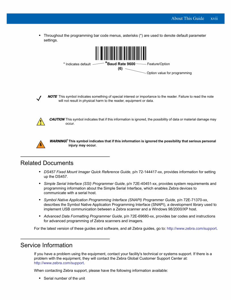
• Throughout the programming bar code menus, asterisks (*) are used to denote default parameter settings.
Related Documents• DS457 Fixed Mount Imager Quick Reference Guide, p/n 72-144417-xx, provides information for setting
up the DS457.
• Simple Serial Interface (SSI) Programmer Guide, p/n 72E-40451-xx, provides system requirements and programming information about the Simple Serial Interface, which enables Zebra devices to communicate with a serial host.
• Symbol Native Application Programming Interface (SNAPI) Programmer Guide, p/n 72E-71370-xx, describes the Symbol Native Application Programming Interface (SNAPI), a development library used to implement USB communication between a Zebra scanner and a Windows 98/2000/XP host.
• Advanced Data Formatting Programmer Guide, p/n 72E-69680-xx, provides bar codes and instructions for advanced programming of Zebra scanners and imagers.
For the latest version of these guides and software, and all Zebra guides, go to: http://www.zebra.com/support.
Service InformationIf you have a problem using the equipment, contact your facility's technical or systems support. If there is a problem with the equipment, they will contact the Zebra Global Customer Support Center at: http://www.zebra.com/support.
When contacting Zebra support, please have the following information available:
• Serial number of the unit
*Baud Rate 9600(6)
Feature/Option* Indicates default
Option value for programming
NOTE This symbol indicates something of special interest or importance to the reader. Failure to read the note will not result in physical harm to the reader, equipment or data.
CAUTION This symbol indicates that if this information is ignored, the possibility of data or material damage may occur.
WARNING! This symbol indicates that if this information is ignored the possibility that serious personal injury may occur.

xviii DS457 Fixed Mount Imager Integration Guide
• Model number or product name
• Software type and version number
Zebra responds to calls by e-mail, telephone or fax within the time limits set forth in service agreements.
If your problem cannot be solved by Zebra support, you may need to return your equipment for servicing and will be given specific directions. Zebra is not responsible for any damages incurred during shipment if the approved shipping container is not used. Shipping the units improperly can possibly void the warranty.
If you purchased your business product from a Zebra business partner, please contact that business partner for support.

CHAPTER 1GETTING STARTED
Overview
The DS457 fixed-mount imager is specifically designed for standalone applications and OEM applications. The imager is extremely compact, provides easy and flexible integration into a host device, and offers high-performance imaging on 1D and 2D bar codes. The DS457 is ideal for a wide variety of uses: zero-footprint point-of-sale, kiosks, embedded diagnostic equipment, conveyor belts, and many more.
Figure 1-1 DS457 Fixed Mount Imager
This integration guide includes programming parameters and describes the theory of operation, installation, specifications, and configuration.
CAUTION Use of controls, adjustments or procedures other than those specified here can result in hazardous laser light exposure.!
Indicator LED
Trigger Button I/O ConnectorImager Window

1 - 2 DS457 Fixed Mount Imager Integration Guide
DS457 Features• Quick and easy integration for OEM devices
• Excellent imaging performance on all 1D and 2D bar codes
• RS-232 (serial) or USB interface
• Excellent motion tolerance
• LEDs indicating power status and successful decodes
• Trigger button for manual triggering
• Small footprint optimal for "Zero Footprint" POS scanning applications
• Direct Part Marking (DPM) support (DPM version only). Scan 2D symbols etched directly onto an item’s surface (via laser etching and dot peening) for permanent identification.
• Driver's license (DL) parsing (DL version only)
• Easy programming and configuration
• Integrated threaded mounting screw holes
• Flexible mounting options
• IP54 sealing
Theory of Operation During image capture:
1. The image sensor array in the embedded SE4500 imaging engine captures an image of the bar code through the engine’s optical lens. If necessary, the engine automatically adjusts illumination, exposure, and other parameters to obtain the best quality image.
2. The imaging engine sends the image to the DS457 CPU.
3. The DS457 CPU processes the image to identify the target bar code(s), decodes them, and transmits the decoded data to the host.
Set various parameters provided in this guide to adjust the performance of the DS457 to match the application or desired usage profile.

Getting Started 1 - 3
Block Diagram The DS457 imager block diagram illustrates the functional relationship of the DS457 components. This section also provides a description of each component in the block diagrams.
Figure 1-2 DS457 Block Diagram
LED Illumination Driver
SE4500 Engine
Illumination LEDs
Laser Aimer Laser Aimer Driver Microprocessor
WVGA Sensor
Internal Beeper Internal Trigger
Interface CircuitryGreen/Red LEDs
PXA320MIcrorprocessor, RAM, and Flash
Power Regulation
Decoder/Interface
DB-9 Connector
User Interface Drivers

1 - 4 DS457 Fixed Mount Imager Integration Guide
DS457 Block Diagram Descriptions SE4500 Imaging Engine - The SE4500 imaging engine captures 8-bit gray scale WVGA images at up to 60 fps, which are sent uncompressed to a companion board for processing. The engine uses a red laser for intuitive aiming and features LED illumination. The engine is available in two focusing configurations, providing a choice between high resolution and longer depth of field.
DS457 Decoder/Interface Board - The decoder/interface board is a companion decoder module for the SE4500 imaging engine, which controls the engine, receives images, decodes 1D and 2D symbologies, and performs various image processing tasks. The board controls a beeper and red and green LEDs for acoustic and visual feedback, respectively. It also provides imaging for an external trigger and external beeper via the DB9 connector. The board supports asynchronous serial (the standard Symbol Simple Serial Interface/SSI command set) and SNAPI (Symbol Native API) interfaces, as well as a variety of other USB and RS-232 host interfaces.
DB9 - The DB9 connector provides an outlet for the various interface signals used between the DS457 and the host. It also provides power to the unit.
Getting Started 1 - 5
DS457 Decoder/Interface Board
Marvell PXA320 ProcessorThe digital system is built on a Marvell PXA320 (Intel XScale®) super-pipelined RISC microarchitecture core. The major features of the core are:
• CPU clock speed up to 624 MHz with external DDR SDRAM bus speed of 133 MHz.
• 32 KB instruction/32 KB data L1 cache, 256 KB unified L2 cache, 728 KB internal SRAM
Power ManagementThe DS457 decoder/interface board has various power management options depending on the host interface.
• USB (SNAPI, USB HID Keyboard, etc.) - The DS457 automatically manages its power usage, including USB suspend mode. Additionally, when drawing power from the USB bus, the DS457 does not exceed the USB limit of 500 mA.
• SSI or RS-232 - When using SSI or any RS-232 host interface, the DS457 uses one of the following power modes. See Power Mode (RS-232 Hosts Only) on page 6-17.• Continuous Power: The DS457 is fully awake and running, even when not in a decode session.• Low Power (default): The DS457 draws less current at idle than when in Continuous Power mode.

1 - 6 DS457 Fixed Mount Imager Integration Guide

CHAPTER 2INSTALLATION
OverviewThis chapter provides information on unpacking, mounting, and installing the imager.
UnpackingRemove the DS457 from its packing and inspect for damage. If the imager is damaged, call Zebra Global Customer Support on page xvii.
KEEP THE PACKING. It is the approved shipping container and should be used if the equipment needs to be returned for servicing.

2 - 2 DS457 Fixed Mount Imager Integration Guide
Mounting There are two M3 x .5 tapped holes on the bottom of the DS457 housing for mounting. The following figures provide the mounting dimensions.
DS457 Mounting Dimensions
Figure 2-1 DS457 Mounting Dimensions
NOTE Do not use screws that penetrate more than 3.5 mm into the bottom mousing of the DS457 since this is the maximum depth of the useful thread.
Note: Dimensions are in mm.
Installation 2 - 3
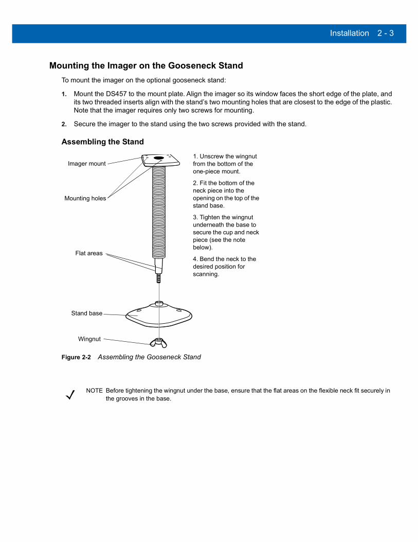
Mounting the Imager on the Gooseneck Stand
To mount the imager on the optional gooseneck stand:
1. Mount the DS457 to the mount plate. Align the imager so its window faces the short edge of the plate, and its two threaded inserts align with the stand’s two mounting holes that are closest to the edge of the plastic. Note that the imager requires only two screws for mounting.
2. Secure the imager to the stand using the two screws provided with the stand.
Assembling the Stand
Figure 2-2 Assembling the Gooseneck Stand
Stand base
Wingnut
1. Unscrew the wingnut from the bottom of the one-piece mount.
2. Fit the bottom of the neck piece into the opening on the top of the stand base.
3. Tighten the wingnut underneath the base to secure the cup and neck piece (see the note below).
4. Bend the neck to the desired position for scanning.
Imager mount
Flat areas
Mounting holes
NOTE Before tightening the wingnut under the base, ensure that the flat areas on the flexible neck fit securely in the grooves in the base.

2 - 4 DS457 Fixed Mount Imager Integration Guide
Mounting the Stand (optional)You can attach the base of the stand to a flat surface using two screws or double-sided tape (not provided).
Screw Mount
1. Position the assembled base on a flat surface.
2. Screw one #10 wood screw into each screw-mount hole until the base of the stand is secure.
Tape Mount
1. Peel the paper liner off one side of each piece of tape and place the sticky surface over each of the three rectangular tape areas.
2. Peel the paper liner off the exposed sides of each piece of tape and press the stand on a flat surface until it is secure.
Figure 2-3 Mounting the Stand
Two screw-mount holes
Double-sided tape areas (3 places)(dimensions = 1” x 2”)

Installation 2 - 5
Mounting the Imager on the POS Stand
To mount the imager on the optional POS stand:
1. Mount the imager to the bracket assembly using the two mounting screws provided.
Figure 2-4 Mounting Imager on Bracket Assembly
2. Secure the microphone-style clip to the mounting surface using the two screws provided.
Figure 2-5 Securing Microphone Clip
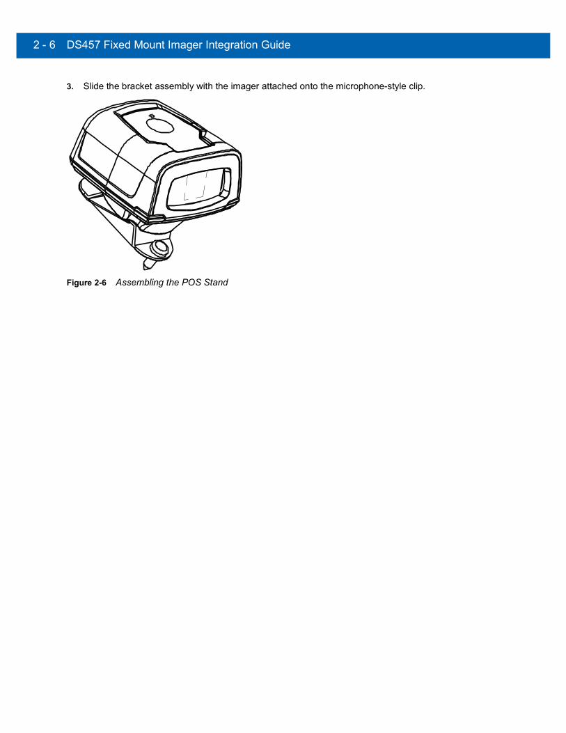
2 - 6 DS457 Fixed Mount Imager Integration Guide
3. Slide the bracket assembly with the imager attached onto the microphone-style clip.
Figure 2-6 Assembling the POS Stand
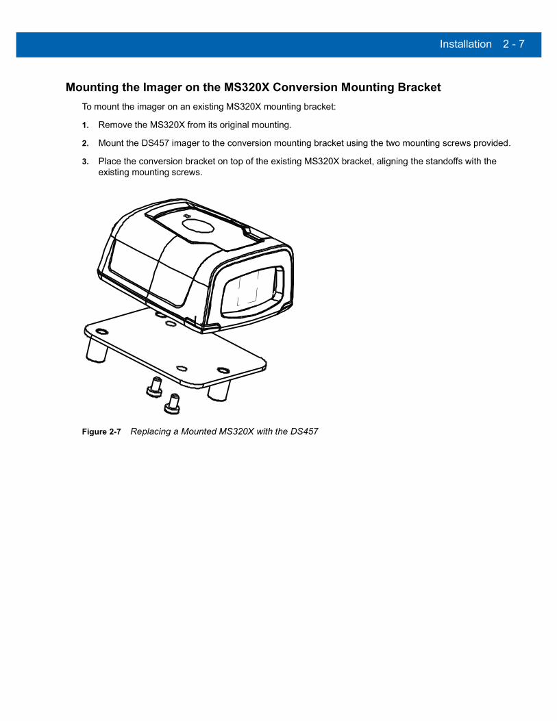
Installation 2 - 7
Mounting the Imager on the MS320X Conversion Mounting Bracket
To mount the imager on an existing MS320X mounting bracket:
1. Remove the MS320X from its original mounting.
2. Mount the DS457 imager to the conversion mounting bracket using the two mounting screws provided.
3. Place the conversion bracket on top of the existing MS320X bracket, aligning the standoffs with the existing mounting screws.
Figure 2-7 Replacing a Mounted MS320X with the DS457
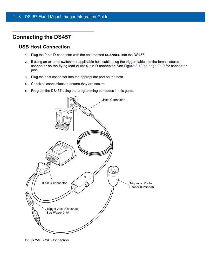
2 - 8 DS457 Fixed Mount Imager Integration Guide
Connecting the DS457
USB Host Connection1. Plug the 9-pin D-connector with the end marked SCANNER into the DS457.
2. If using an external switch and applicable host cable, plug the trigger cable into the female stereo connector on the flying lead of the 9-pin D-connector. See Figure 2-10 on page 2-10 for connector pins.
3. Plug the host connector into the appropriate port on the host.
4. Check all connections to ensure they are secure.
5. Program the DS457 using the programming bar codes in this guide.
Figure 2-8 USB Connection
Trigger or Photo Sensor (Optional)
Host Connector
Trigger Jack (Optional) See Figure 2-10
9-pin D-connector
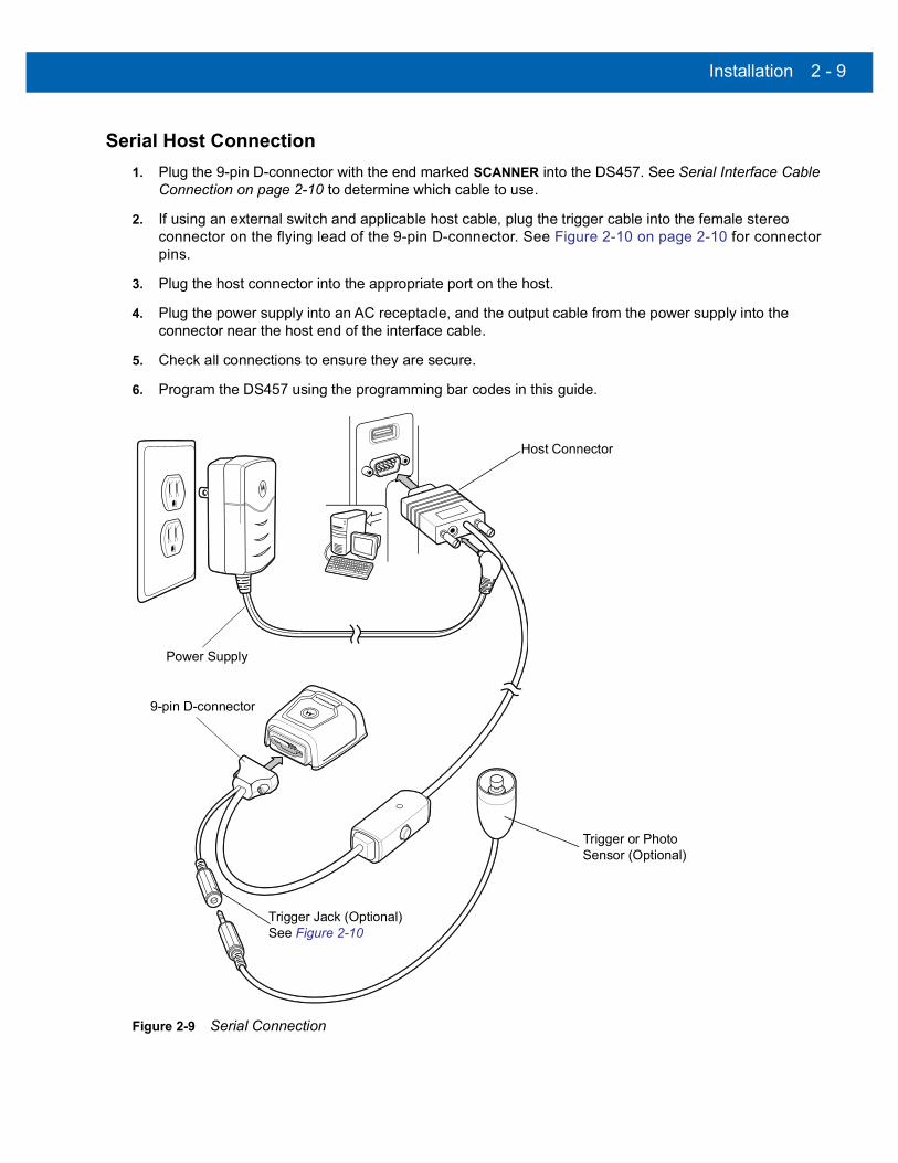
Installation 2 - 9
Serial Host Connection
1. Plug the 9-pin D-connector with the end marked SCANNER into the DS457. See Serial Interface Cable Connection on page 2-10 to determine which cable to use.
2. If using an external switch and applicable host cable, plug the trigger cable into the female stereo connector on the flying lead of the 9-pin D-connector. See Figure 2-10 on page 2-10 for connector pins.
3. Plug the host connector into the appropriate port on the host.
4. Plug the power supply into an AC receptacle, and the output cable from the power supply into the connector near the host end of the interface cable.
5. Check all connections to ensure they are secure.
6. Program the DS457 using the programming bar codes in this guide.
Figure 2-9 Serial Connection
Trigger or Photo Sensor (Optional)
Host Connector
Trigger Jack (Optional) See Figure 2-10
9-pin D-connector
Power Supply

2 - 10 DS457 Fixed Mount Imager Integration Guide
Serial Interface Cable ConnectionWhen connecting via RS-232, identify the type of host system to determine the cable needed. If you are unsure what host system you are using, contact the local Zebra representative.
TTL Level Compatible RS-232 Host Systems
If using a PC, laptop, or POS terminal, the host system most likely has an RS-232 port which is compatible with TTL levels. In this case, use the standard 5V RS-232 cable.
Host Systems Which Require True RS-232 Levels
Some host devices are not compatible with TTL level signals and require true RS-232 levels, such as those in electrically noisy environments and locations with long cable runs. In such installations the DS457 may require a level-shifting cable, such as p/n 25-62186-03R, to interface to this host system.
Failure to use the appropriate cable can impact the imager’s ability to reliably communicate with the host under some conditions.
Trigger Jack Connector Pins
Figure 2-10 Trigger Jack Connector Pins
Location and PositioningThe location and positioning guidelines do not consider unique application characteristics. Zebra recommends that an opto-mechanical engineer perform an opto-mechanical analysis prior to integration.
Male jack shown for reference
Note: Due to many variations of jack and socket styles, identify terminals as shown before soldering leads.
1 1
2
2
33
InsertionDirection
1 - Ground (Sleeve)2 - Battery (Middle Contact)3 - Trigger (Tip)
1 - Ground (Sleeve)2 - Vcc (Middle Contact)3 - Trigger (Tip)
NOTE Integrate the imager in an environment no more extreme than the product’s specification, where the imager will not exceed its temperature range. For instance, do not mount the imager onto or next to a large heat source. When placing the imager with another device, ensure there is proper convection or venting for heat. Follow these suggestions to ensure product longevity, warranty, and overall satisfaction with the imager.

Installation 2 - 11
Embedded Applications Requiring a Window Use the following guidelines for applications that require a window in front of the DS457.
Window Material
Many window materials that look perfectly clear can contain stresses and distortions that can reduce imager performance. For this reason, Zebra highly recommends optical glass or cell-cast acrylic. Following is a description of acrylic and CR-39, another popular window material. Table 2-1 outlines the suggested window properties.
Acrylic (PMMA)When fabricated by cell-casting, acrylic has very good optical quality and low initial cost. However, protect the surface from the environment as acrylic is susceptible to attack by chemicals, mechanical stresses, and UV light. Acrylic has reasonably good impact resistance and can be ultrasonically welded.
CR-39 (ADC)CR-39 is a thermal-setting plastic produced by the cell-casting process, and is commonly used in plastic eye glasses lenses. CR-39 has excellent chemical and environmental resistance, including good surface hardness. Typically it does not require hard-coating, but can be hard coated for severe environments. CR-39 has reasonably good impact resistance and cannot be ultrasonically welded.
Chemically Tempered Float GlassGlass is a hard material which provides excellent scratch and abrasion resistance. However, unannealed glass is brittle. Increasing flexibility strength with minimal optical distortion requires chemical tempering. Glass cannot be ultrasonically welded and is difficult to cut into odd shapes.
NOTE Zebra does not recommend placing an exit window in front of the DS457; however, the following information is provided for applications that require such a window.
NOTE Consider the following window placement and material recommendations if mounting the DS457 within a product with its own window.
CAUTION Consult an opto-mechanical engineer to recommend an appropriate window material and to determine if coatings are appropriate for the specific application.!
NOTE Do not use polycarbonate material.
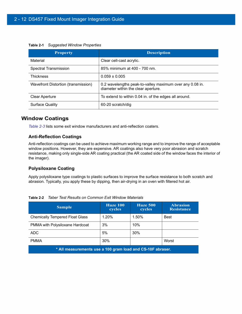
2 - 12 DS457 Fixed Mount Imager Integration Guide
Window CoatingsTable 2-3 lists some exit window manufacturers and anti-reflection coaters.
Anti-Reflection CoatingsAnti-reflection coatings can be used to achieve maximum working range and to improve the range of acceptable window positions. However, they are expensive. AR coatings also have very poor abrasion and scratch resistance, making only single-side AR coating practical (the AR coated side of the window faces the interior of the imager).
Polysiloxane CoatingApply polysiloxane type coatings to plastic surfaces to improve the surface resistance to both scratch and abrasion. Typically, you apply these by dipping, then air-drying in an oven with filtered hot air.
Table 2-1 Suggested Window Properties
Property Description
Material Clear cell-cast acrylic.
Spectral Transmission 85% minimum at 400 - 700 nm.
Thickness 0.059 ± 0.005
Wavefront Distortion (transmission) 0.2 wavelengths peak-to-valley maximum over any 0.08 in. diameter within the clear aperture.
Clear Aperture To extend to within 0.04 in. of the edges all around.
Surface Quality 60-20 scratch/dig
Table 2-2 Taber Test Results on Common Exit Window Materials
Sample Haze 100 cycles
Haze 500 cycles
Abrasion Resistance
Chemically Tempered Float Glass 1.20% 1.50% Best
PMMA with Polysiloxane Hardcoat 3% 10%
ADC 5% 30%
PMMA 30% Worst
* All measurements use a 100 gram load and CS-10F abraser.

Installation 2 - 13
Embedded Window Angle and PositionIf you are placing a window between the DS457 and the target, observe the following guidelines:
• Window Clear Opening - Make the clear opening of the window large enough so that the entire imager clear aperture passes through the window. Cutting off any part of the clear aperture can degrade decode range performance. Ensure that window placement relative to the DS457 accounts for tolerances on all parts involved in that assembly.
• Window Angle - Minimum window tilt is indicated in Table 2-4 on page 2-15. Further tilting the window is acceptable and decreases the possibility of a secondary reflection from that window degrading the imager's performance.
• Minimum Window Distance - 5 mm.
• Optical Working Range - Adding a window can reduce the working range of the imager since there is a signal loss when passing through window material. To minimize this reduction, use a special coating described in Window Coatings on page 2-12. To understand the difference, test the imager in the desired orientation and see if the difference affects imager performance.
Table 2-3 Window Manufacturers and Coaters
Company Discipline Specifics
Evaporated Coatings, Inc.2365 Maryland RoadWillow Grove, PA 19090(215) 659-3080
Anti-reflection coater Acrylic window supplier Anti-reflection coater
Fosta-Tek Optics, Inc.320 Hamilton StreetLeominster, MA 01453(978) 534-6511
Cell-caster, hard coater, laser cutter
CR39 exit window manufacturer
Optical Polymers Int. (OPI)110 West Main StreetMilford, CT 06460(203) 882-9093
CR-39 cell-caster, coater, laser cutter
CR39 exit window manufacturer
Polycast70 Carlisle PlaceStamford, CT 06902(800) 243-9002
Acrylic cell-caster, hard coater, laser cutter
Acrylic exit window manufacturer
TSP2009 Glen ParkwayBatavia, OH 45103(800) 277-9778
Acrylic cell-caster, coater, laser cutter
Acrylic exit window manufacturer
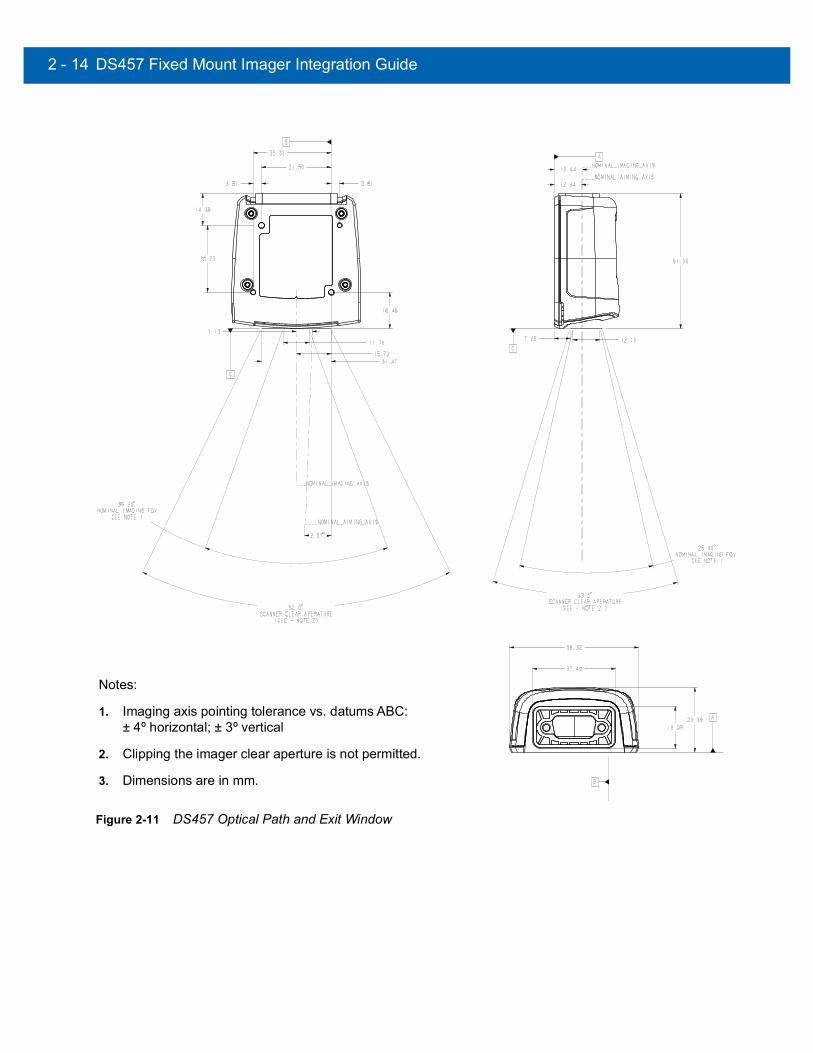
2 - 14 DS457 Fixed Mount Imager Integration Guide
Figure 2-11 DS457 Optical Path and Exit Window
Notes:
1. Imaging axis pointing tolerance vs. datums ABC: ± 4º horizontal; ± 3º vertical
2. Clipping the imager clear aperture is not permitted.
3. Dimensions are in mm.

Installation 2 - 15
Recommended Exit Window Information
Figure 2-12 Window Distances
Exit Window Notes• Integration tolerances are not included.
• Ensure the window size is large enough to cover the engine clear aperture specified in Figure 2-11 plus mounting tolerances of the window relative to the engine.
Table 2-4 Recommended Exit Window Information - Tilted Window
External Window Specification Minimum Window Angle
Non-coated, minimum window positive tilt (+c) 31o
Non-coated, minimum window negative tilt (-c) 31o
AR coated, one side, minimum window positive tilt (+c) 26o
AR coated, one side, minimum window negative tilt (-c) 27o
AR coated, two sides, minimum window positive tilt (+c) 23o
AR coated, two sides, minimum window negative tilt (-c) 17o
Note: Minimum external window distance b = 5 mm (see Table 2-4).

2 - 16 DS457 Fixed Mount Imager Integration Guide
Accessories Zebra offers the following accessories for the imager. Refer to Solution Builder (ordering guide).
Table 2-5 DS457 Imager Accessories
Accessory Part Number
Power Supplies (RS-232)*
5 VDC 850 mA; US, Canada, Mexico, Japan, Taiwan PWRS-14000-253R
5 VDC 850 mA; EU, UK, EMEA, Russia, South Africa PWRS-14000-256R
5 VDC 850 mA; China PWRS-14000-257R
5 VDC 850 mA; Australia, Hong Kong, New Zealand PWRS-14000-258R
5 VDC 850 mA; Argentina, Uruguay PWRS-14000-259R
RS-232
9-Pin female (DB9) with straight connector, 6 ft, with trigger jack, no beeper 25-13227-03R
9-Pin female (DB9) with straight connector, 6 ft, with trigger jack and beeper 25-13228-03R
9-Pin female (DB9) with straight connector, 6 ft, no trigger jack or beeper 25-58918-02R
9-Pin female (DB9) coiled, 9 ft, no trigger jack or beeper 25-58918-03R
9-Pin female (DB9) with straight connector, 6 ft, with trigger jack and no hardware handshaking
25-63736-02R
TTL RS-232 to true RS-232 conversion cable, low profile connector 25-62186-03R
USB
9-Pin female (DB9) with straight connector, 6 ft, with trigger jack and beeper 25-58925-02R
9-Pin female (DB9) with straight connector, 6 ft, no trigger jack or beeper 25-58926-04R
9-Pin female (DB9), 18 in, no trigger jack or beeper (for kiosks) 25-58926-05R
9-Pin female (DB9), coiled, 9 ft, no trigger jack or beeper 25-58926-06R
Optional Accessories
Push button trigger cable 25-04950-01R
Photo sensor trigger cable (retroreflective, IR 850nm, 7 foot range) 25-13176-01R
Gooseneck stand (twilight black) 20-60136-02R
POS wall/counter mount KT-145344-01
MS320x to DS457 conversion mounting bracket KT-152342-01
*Standalone power supply is not used for USB hosts.

Installation 2 - 17
Simple Serial Interface Software Developer's Kit (SSI SDK)
The SSI Software Developer's Kit, available on Zebra’s website, provides the software tools used to integrate and communicate with the DS457 imagers via RS-232, including:
• Sample Windows® program with source code
• DLL with source code for building user applications
• ActiveX component (including help file) for easy integration into VisualBasic programs
• Simple Serial Interface documentation.
With over 70 programmable parameters, you can configure DS457 imagers using bar code menus, or through the serial interface using Zebra’s Simple Serial Interface protocol.
For Windows®, DOS, and embedded system environments, this enables you to take full advantage of the imager’s features and obtain maximum performance.
To download the SDK, go to: http://www.zebra.com/support.
Zebra SNAPI Software Developer's Kit The Symbol Native Application Programming Interface Software Development Kit (SNAPI SDK) facilitates communicate with SNAPI-based Zebra scanners over USB, providing the following features:
• Bar code capture and decode
• Image and video capture
• Electronic scanner configuration and software update
• Reference sample application in Microsoft Visual C#® .NET.
To download the SDK, go to: http://www.zebra.com/support.

2 - 18 DS457 Fixed Mount Imager Integration Guide
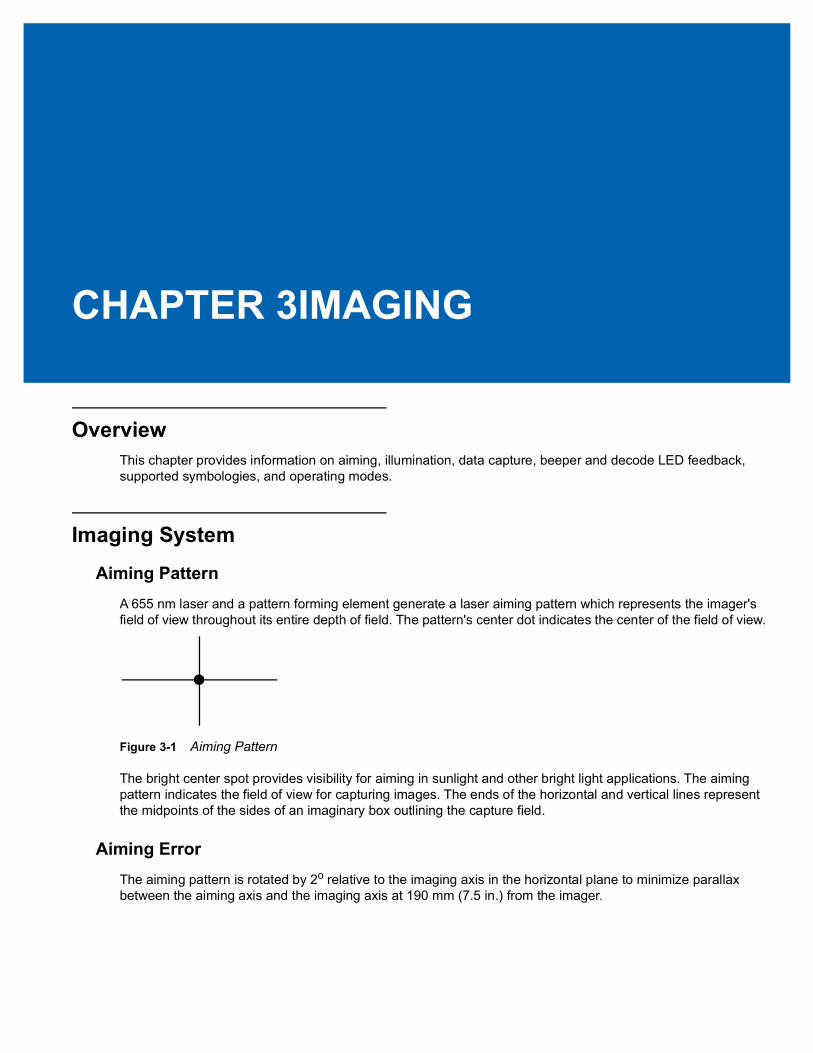
CHAPTER 3IMAGING
OverviewThis chapter provides information on aiming, illumination, data capture, beeper and decode LED feedback, supported symbologies, and operating modes.
Imaging System
Aiming PatternA 655 nm laser and a pattern forming element generate a laser aiming pattern which represents the imager's field of view throughout its entire depth of field. The pattern's center dot indicates the center of the field of view.
Figure 3-1 Aiming Pattern
The bright center spot provides visibility for aiming in sunlight and other bright light applications. The aiming pattern indicates the field of view for capturing images. The ends of the horizontal and vertical lines represent the midpoints of the sides of an imaginary box outlining the capture field.
Aiming ErrorThe aiming pattern is rotated by 2o relative to the imaging axis in the horizontal plane to minimize parallax between the aiming axis and the imaging axis at 190 mm (7.5 in.) from the imager.

3 - 2 DS457 Fixed Mount Imager Integration Guide
Aiming Control
The DS457 can capture images with both the aiming subsystem turned on during exposure (the image of the aiming pattern is visible in the digital image) or off. If the aiming system is turned off during exposure, brightness of the aiming pattern decreases as exposure increases.
Illumination SystemThe illumination system consists of two high-output, red LEDs (625 nm) and a sophisticated drive system that allows image capture and decoding throughout a full range of lighting conditions (total darkness to full sunlight).
Illumination ControlThe DS457 can capture images with the illumination subsystem turned on or off, accommodating images that are close to the wavelength of the illumination. For example, since the imager uses red LED illumination, it may be desirable to shut off the illumination when capturing an image printed in red ink.
It is recommended to turn off LED illumination and provide minimum 30 fcd ambient light on the document surface when taking images of documents. Even a small amount of dust or fingerprints on the imager window can scatter the LED illumination and create glare in the image. The glare reduces quality of document images but does not affect bar code reading.
Frame Rate ControlThe DS457 outputs images at 60 frames per second by default. When capturing images, use lower frame rates to increase image brightness. The aiming pattern and illumination appear to blink when the frame rate is 30 fps or lower.

Imaging 3 - 3
Capturing DataWhen scanning, the imager projects a red laser aiming pattern which allows positioning the bar code within its field of view. See Decode Zones on page 4-6 for the proper distance to achieve between the imager and a bar code. The imager turns on its red LEDs to illuminate the target bar code.
In Presentation Mode (default), when the DS457 detects an object in its field of view, it automatically triggers and displays the aiming pattern. In triggered mode, press the trigger button on top of the imager to display the aiming pattern.
To scan a bar code, center the symbol in any orientation within the aiming pattern. Be sure the entire symbol is within the rectangular area formed by the cross pattern.
Figure 3-2 Scanning Orientation with Imager Aiming Pattern
The imager can also read a bar code presented within the aiming pattern but not centered. The top examples in Figure 3-3 show acceptable aiming options, while the bottom examples can not be decoded.
Figure 3-3 Acceptable and Incorrect Aiming
Upon successful decode, the DS457 beeps and its feedback LED turns green.
1D bar code symbol 2D bar code symbol 2D dot peen DPM symbol
0 1 2 3 4 5
0 1 2 3 4 5
0 1 2 3 4 5
0 1 2 3 4 5

3 - 4 DS457 Fixed Mount Imager Integration Guide
Beeper and Decode LED Indications Table 3-1 provides beeper and LED indications related to certain events. The LED illuminates red to indicate that the imager has power. SSI events are also listed.
Table 3-1 User Interface Indications
DescriptionIndication
SSI EventBeeper Power/Decode
LED
Trigger pull No sound Red TRIGGER_PULLED
No decode NODECODE_MSG
Wakeup WAKEUP
Video is off VIDEO_OFF
Video is on VIDEO_ON
Decode Middle Tone Flash of green DECODE
Snapshot started Low Tone Blinking green SNAPSHOT_START
Snapshot is complete Low Tone Red SNAPSHOT_COMPLETE
Bootup Low Tone, Middle Tone, High Tone
Red BOOTUP
Transmission error Four Low Tones Red TRANSMIT_ERROR
Entry error Low Tone, High Tone Flash of green ENTRY_ERROR
Defaults set High Tone, Low Tone, High Tone, Low Tone
Flash of green DEFAULTS_SET
Parameter entered PARAM_ENTERED
Number entry expected High Tone, Low Tone Flash of green NUMBER_EXPECTED

Imaging 3 - 5
Supported SymbologiesThe following bar code types are supported and can be individually enabled or disabled:
1D Symbologies 2D Symbologies
UPC/EAN PDF417Bookland EAN MicroPDF417UCC Coupon Code Data MatrixISSN EAN Data Matrix InverseCode 128 MaxicodeGS1-128 QR CodeISBT 128 MicroQRCode 39 QR InverseTrioptic Code 39 AztecCode 32 Aztec InverseCode 93Code 11 Postal CodesInterleaved 2 of 5 US PostnetDiscrete 2 of 5 US PlanetCodabar UK PostalMSI Japan PostalChinese 2 of 5 Australian PostalMatrix 2 of 5 Netherlands KIX CodeKorean 3 of 5 USPS 4CB/One Code/Intelligent MailInverse 1D UPU FICS PostalGS1 DataBarComposite Codes
Operating ModesThe DS457 supports the following operating modes. See Operational Modes on page 7-4 for information on changing between modes.
• Decode (default mode) - for decoding a bar code
• Snapshot - for capturing an image
• Snapshot with Viewfinder Mode - provides a video of the subject until a snapshot of the image is captured.
• Video - provides a video of the subject

3 - 6 DS457 Fixed Mount Imager Integration Guide

CHAPTER 4SPECIFICATIONS
Electrical Interface
Figure 4-1 DS457 Connector
Table 4-1 lists the pin functions of the DS457 interface.
Table 4-1 DS457 USB and Serial Electrical Interface
USB Interface Serial Interface
Pin No. Pin Name Pin No. Pin Name
1 Trigger 1 Trigger
2 NC 2 TXD Output TTL Only
3 USB + 3 RXD Input TTL Only
4 Connect to Pin 8 4 NC
5 Ground 5 Ground
6 +5V Power 6 +5V Power
7 USB - 7 CTS Input TTL Only
8 Connect to Pin 4 8 RTS Output TTL Only
9 Beeper/Download 9 Beeper/Download
NC = No Connect (do not connect this pin)

4 - 2 DS457 Fixed Mount Imager Integration Guide
Dimension Drawings
Figure 4-2 DS457 Dimension Drawings
62.0 mm
29.2 mm
58.4 mm
Back View

Specifications 4 - 3
DS457 Imager Technical Specifications
Table 4-2 DS457 Technical Specifications at 23° C
Item Description
Performance Characteristics
Sensor Resolution 752 x 480 pixels
Field of View DS457-SR/DL: 39.6º horizontal, 25.7º verticalDS457-HD/DP: 38.4º horizontal, 24.9º vertical
Pitch/Skew/Roll Tolerance ± 60º / ± 60º / 360º (see Figure 4-3 on page 4-5)
Focal Distance from Front of Imager Housing
DS457-SR/DL: 4.7 in. DS457-HD/DP: 2.3 in.
Aiming Element (VLD) 655 nm ± 10 nm
Illumination Element 625 nm ± 5 nm (LED)
Minimum Print Contrast 25% absolute dark/light reflectance
User Environment
Power RequirementsSupply Voltage Low Power / Suspend Current DrawIdle CurrentOperating Current (scan/decode session)Peak Current
5.00 V ± 0.5 V
2.5 mA (typical)160 mA (typical)
280 mA (average)450 mA
Ambient Light Immunity Total darkness to 9,000 ft. candles (96,900 lux)
HumidityOperating Storage
95% RH, non-condensing at 50º C 85% RH, non-condensing at 70º C
Drop Rating Unit functions normally after multiple 30 in (76 cm) drops to tile over concrete
TemperatureOperating Storage
-4º to 122º F (-20º to 50º C)*-40º to 158º F (-40º to 70º C)* Above 45ºC the laser aimer is disabled. In high temperature environments the DS457 safeguards the laser from overheating by monitoring the internal system temperature. For this reason, if Time Delay to Presentation Idle Mode is set to a high value and the aiming pattern remains on for an extended period of time while in presentation mode, the imager may temporarily shut off the aiming pattern.
Note: Environmental and/or tolerance parameters are not cumulative. Perform a thermal analysis if the application is subject to an extreme temperature environment.

4 - 4 DS457 Fixed Mount Imager Integration Guide
Skew, Pitch and Roll
Measured on a 20 mil Code 39 symbol at a distance of 10 inches. Tolerance is reduced at extreme ends of the working range.
Dimensions 1.15 in. (29.2 mm) H x 2.30 in. (58.4 mm) W x 2.44 in. (62.0 mm) D
Weight 3.9 oz. (111.0 grams)
Interface 9-pin male D-sub supports USB (full speed) and TTL level RS-232 with RTS and CTS
Table 4-2 DS457 Technical Specifications at 23° C (Continued)
Item Description
Note: Environmental and/or tolerance parameters are not cumulative. Perform a thermal analysis if the application is subject to an extreme temperature environment.
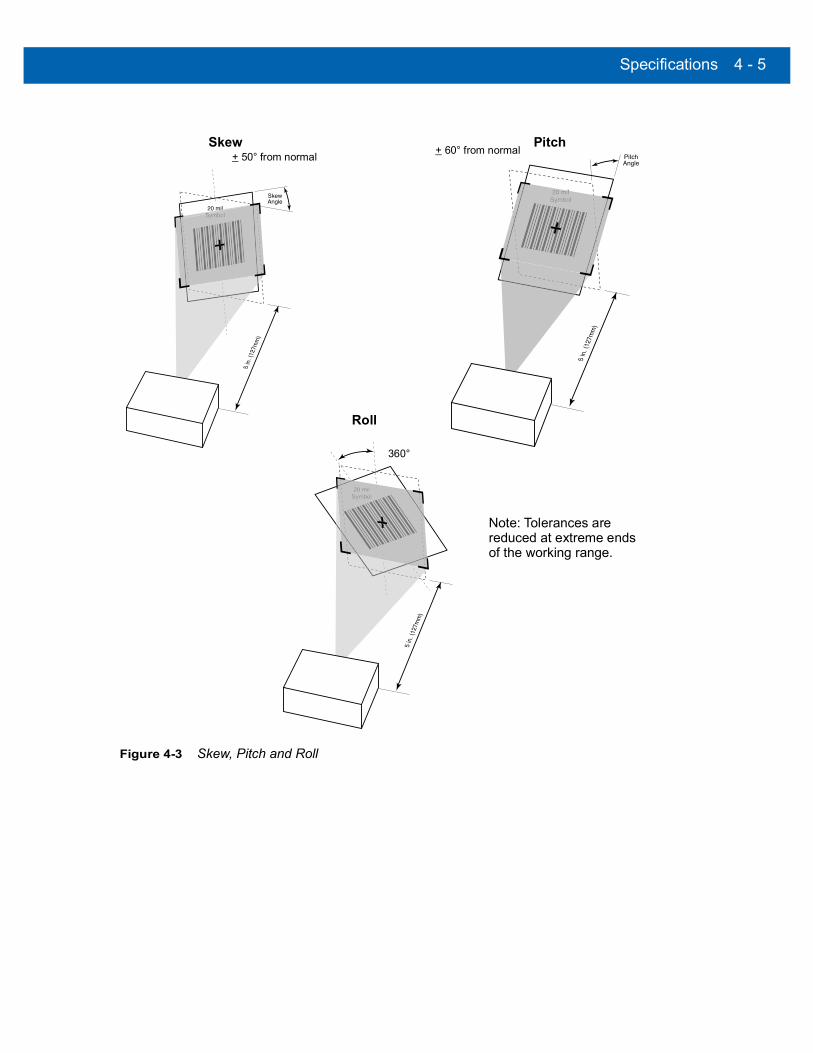
Specifications 4 - 5
Figure 4-3 Skew, Pitch and Roll
Skew Pitch
Roll
Note: Tolerances are
of the working range.reduced at extreme ends
+ 50° from normal + 60° from normal
360°

4 - 6 DS457 Fixed Mount Imager Integration Guide
Decode Zones
DS457-SR/DL
Figure 4-4 shows the decode zone for the DS457-SR/DL. Typical values appear. Table 4-3 lists the typical and guaranteed distances for selected bar code densities. The minimum element width (or “symbol density”) is the width in mils of the narrowest element (bar or space) in the symbol.
Figure 4-4 DS457-SR/DL Decode Zone - 1D and Data Matrix Symbols
In.cm
0
20 mil Code 39
Depth of Field
16.5
4 8 12 16 200 10.2 20.3 30.5 40.6 50.8
13 mil (100% UPC)1.5 15.3
0
Width
of
Field
0
10 25.4
20 50.8
50.820
25.4
in.Note: Typical performance at 73˚F (23˚C) on high quality symbols.
DS457-SR/DL
10
10.915 mil Data Matrix
8.410 mil Data Matrix
5 mil Code 391.3 8.1
7.5 mil Data Matrix2.0 6.0
1.5
1.6
1.8
cm

Specifications 4 - 7
Figure 4-5 DS457-SR/DL Decode Zone - QR Code and PDF417 Symbols
In.cm
0
15 mil PDF417
Depth of Field
13.0
4 8 12 160 10.2 20.3 30.5 40.6
10 mil PDF4171.2 10.2
0
Width
of
Field
0
10 25.4
20 50.8
50.820
25.4
in.Note: Typical performance at 73˚F (23˚C) on high quality symbols.
DS457-SR/DL
10
7.16.67 mil PDF417
7.010 mil QR Code
5 mil PDF4172.4 6.2
7.5 mil QR Code2.1 5.1
1.5
1.8
1.5
cm
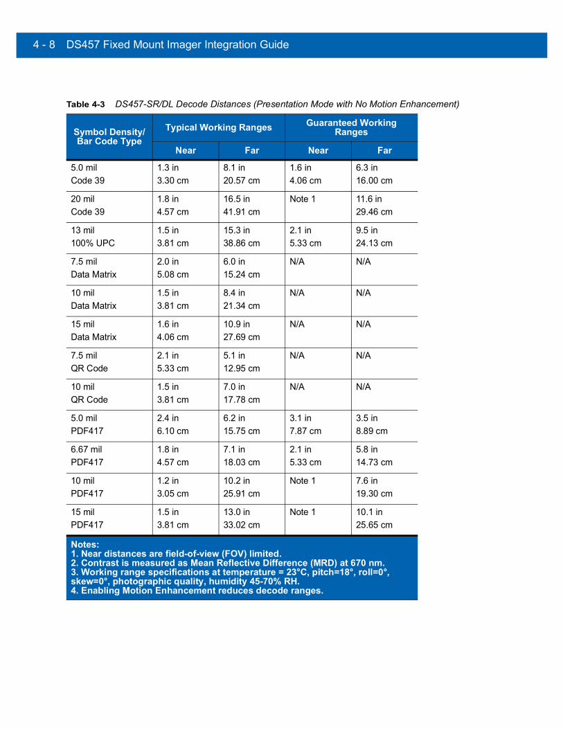
4 - 8 DS457 Fixed Mount Imager Integration Guide
Table 4-3 DS457-SR/DL Decode Distances (Presentation Mode with No Motion Enhancement)
Symbol Density/Bar Code Type
Typical Working Ranges Guaranteed Working Ranges
Near Far Near Far
5.0 milCode 39
1.3 in3.30 cm
8.1 in20.57 cm
1.6 in4.06 cm
6.3 in16.00 cm
20 milCode 39
1.8 in4.57 cm
16.5 in41.91 cm
Note 1 11.6 in29.46 cm
13 mil100% UPC
1.5 in3.81 cm
15.3 in38.86 cm
2.1 in5.33 cm
9.5 in24.13 cm
7.5 milData Matrix
2.0 in5.08 cm
6.0 in15.24 cm
N/A N/A
10 milData Matrix
1.5 in3.81 cm
8.4 in21.34 cm
N/A N/A
15 milData Matrix
1.6 in4.06 cm
10.9 in27.69 cm
N/A N/A
7.5 milQR Code
2.1 in5.33 cm
5.1 in12.95 cm
N/A N/A
10 milQR Code
1.5 in3.81 cm
7.0 in17.78 cm
N/A N/A
5.0 milPDF417
2.4 in6.10 cm
6.2 in15.75 cm
3.1 in7.87 cm
3.5 in8.89 cm
6.67 mil PDF417
1.8 in4.57 cm
7.1 in18.03 cm
2.1 in5.33 cm
5.8 in14.73 cm
10 milPDF417
1.2 in3.05 cm
10.2 in25.91 cm
Note 1 7.6 in19.30 cm
15 milPDF417
1.5 in3.81 cm
13.0 in33.02 cm
Note 1 10.1 in25.65 cm
Notes:1. Near distances are field-of-view (FOV) limited.2. Contrast is measured as Mean Reflective Difference (MRD) at 670 nm.3. Working range specifications at temperature = 23°C, pitch=18°, roll=0°, skew=0°, photographic quality, humidity 45-70% RH.4. Enabling Motion Enhancement reduces decode ranges.
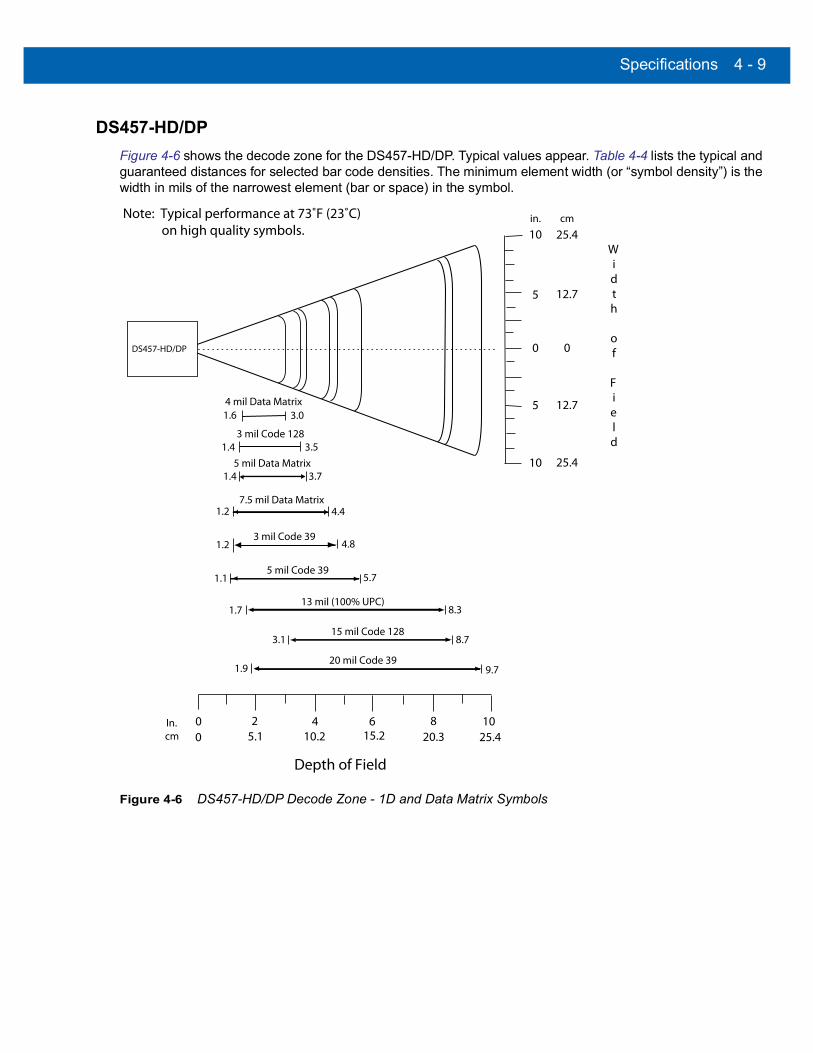
Specifications 4 - 9
DS457-HD/DP
Figure 4-6 shows the decode zone for the DS457-HD/DP. Typical values appear. Table 4-4 lists the typical and guaranteed distances for selected bar code densities. The minimum element width (or “symbol density”) is the width in mils of the narrowest element (bar or space) in the symbol.
Figure 4-6 DS457-HD/DP Decode Zone - 1D and Data Matrix Symbols
In.cm
0
5 mil Code 39
Depth of Field
5.7
2 4 6 8 100 5.1 10.2 15.2 20.3 25.4
3 mil Code 391.2 4.8
0
Width
of
Field
0
5 12.7
10 25.4
25.410
12.7
in.Note: Typical performance at 73˚F (23˚C) on high quality symbols.
DS457-HD/DP
5
4.47.5 mil Data Matrix
3.75 mil Data Matrix
3 mil Code 1281.4 3.5
4 mil Data Matrix1.6 3.0
1.4
1.2
1.1
cm
13 mil (100% UPC)8.31.7
15 mil Code 1288.73.1
20 mil Code 399.71.9

4 - 10 DS457 Fixed Mount Imager Integration Guide
Figure 4-7 DS457-HD/DP Decode Zone - QR Code and PDF417 Symbols
In.cm
0
6.67 mil PDF417
Depth of Field
4.8
2 4 6 8 100 5.1 10.2 15.2 20.3 25.4
10 mil QR Code1.1 4.6
0
Width
of
Field
0
5 12.7
10 25.4
25.410
12.7
in.Note: Typical performance at 73˚F (23˚C) on high quality symbols.
DS457-HD/DP
5
4.07.5 mil QR Code
3.84 mil PDF417
5 mil QR Code
1.5 3.1
1.4
1.1
1.0
cm
20 mil QR Code6.81.4
40 mil QR Code10.43.0
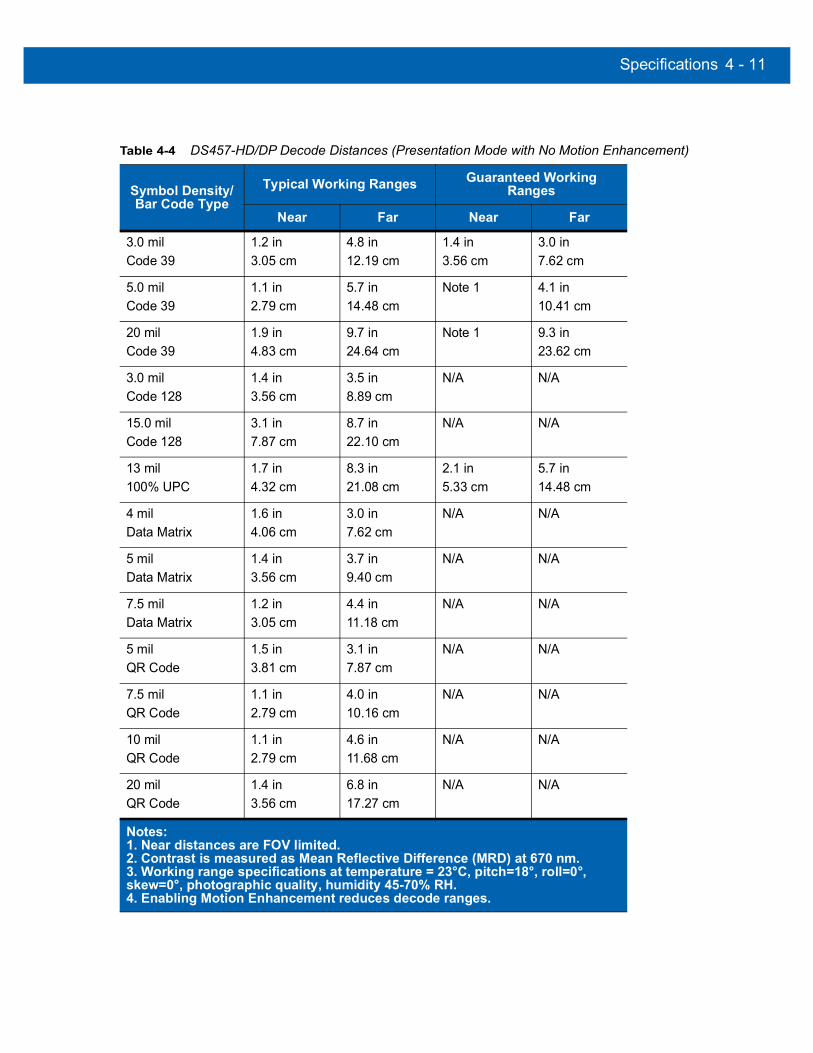
Specifications 4 - 11
Table 4-4 DS457-HD/DP Decode Distances (Presentation Mode with No Motion Enhancement)
Symbol Density/Bar Code Type
Typical Working Ranges Guaranteed Working Ranges
Near Far Near Far
3.0 milCode 39
1.2 in3.05 cm
4.8 in12.19 cm
1.4 in3.56 cm
3.0 in7.62 cm
5.0 milCode 39
1.1 in2.79 cm
5.7 in14.48 cm
Note 1 4.1 in10.41 cm
20 milCode 39
1.9 in4.83 cm
9.7 in24.64 cm
Note 1 9.3 in23.62 cm
3.0 milCode 128
1.4 in3.56 cm
3.5 in8.89 cm
N/A N/A
15.0 milCode 128
3.1 in7.87 cm
8.7 in22.10 cm
N/A N/A
13 mil100% UPC
1.7 in4.32 cm
8.3 in21.08 cm
2.1 in5.33 cm
5.7 in14.48 cm
4 milData Matrix
1.6 in4.06 cm
3.0 in7.62 cm
N/A N/A
5 milData Matrix
1.4 in3.56 cm
3.7 in9.40 cm
N/A N/A
7.5 milData Matrix
1.2 in3.05 cm
4.4 in11.18 cm
N/A N/A
5 milQR Code
1.5 in3.81 cm
3.1 in7.87 cm
N/A N/A
7.5 milQR Code
1.1 in2.79 cm
4.0 in10.16 cm
N/A N/A
10 milQR Code
1.1 in2.79 cm
4.6 in11.68 cm
N/A N/A
20 milQR Code
1.4 in3.56 cm
6.8 in17.27 cm
N/A N/A
Notes:1. Near distances are FOV limited.2. Contrast is measured as Mean Reflective Difference (MRD) at 670 nm.3. Working range specifications at temperature = 23°C, pitch=18°, roll=0°, skew=0°, photographic quality, humidity 45-70% RH.4. Enabling Motion Enhancement reduces decode ranges.
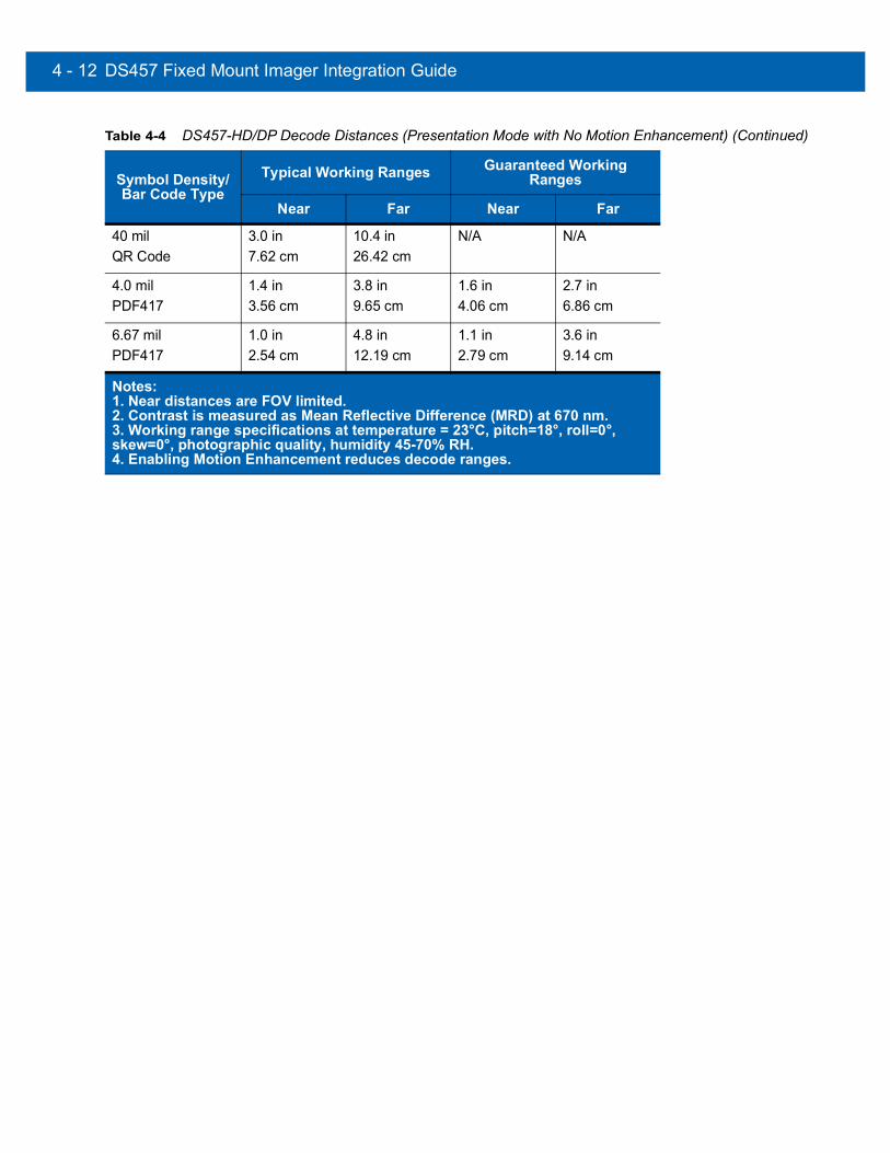
4 - 12 DS457 Fixed Mount Imager Integration Guide
40 milQR Code
3.0 in7.62 cm
10.4 in26.42 cm
N/A N/A
4.0 milPDF417
1.4 in3.56 cm
3.8 in9.65 cm
1.6 in4.06 cm
2.7 in6.86 cm
6.67 mil PDF417
1.0 in2.54 cm
4.8 in12.19 cm
1.1 in2.79 cm
3.6 in9.14 cm
Table 4-4 DS457-HD/DP Decode Distances (Presentation Mode with No Motion Enhancement) (Continued)
Symbol Density/Bar Code Type
Typical Working Ranges Guaranteed Working Ranges
Near Far Near Far
Notes:1. Near distances are FOV limited.2. Contrast is measured as Mean Reflective Difference (MRD) at 670 nm.3. Working range specifications at temperature = 23°C, pitch=18°, roll=0°, skew=0°, photographic quality, humidity 45-70% RH.4. Enabling Motion Enhancement reduces decode ranges.

CHAPTER 5MAINTENANCE & TROUBLESHOOTING
OverviewThe chapter provides information on maintenance and troubleshooting.
MaintenanceClean the imager housing and exit window with a damp cloth and, if necessary, a non-ammonia based detergent. Do not allow any abrasive material to touch the exit window.

5 - 2 DS457 Fixed Mount Imager Integration Guide
Cleaning the Connector1. Remove the cable connector from the imager.
2. Rub a cotton-tipped applicator dipped in isopropyl alcohol back and forth across the connector pins. Do not leave any cotton residue on the connector.
3. Rub a dry cotton-tipped applicator back and forth across the connector pins.
4. Spray compressed air on the connector area by pointing the tube/nozzle about ½ inch away from the surface.
5. Inspect the area for any grease or dirt and repeat if required.
CAUTION Do not get excess alcohol onto the soft elastomeric gasket since this can compromise the adhesion to the housing and ultimately the gasket’s ability to prevent liquids from entering the imager in this area during normal operation.
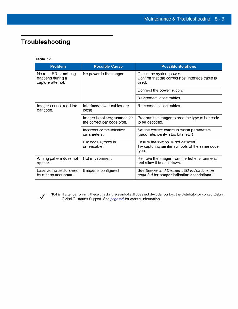
Maintenance & Troubleshooting 5 - 3
Troubleshooting
Table 5-1.
Problem Possible Cause Possible Solutions
No red LED or nothing happens during a capture attempt.
No power to the imager. Check the system power.Confirm that the correct host interface cable is used.
Connect the power supply.
Re-connect loose cables.
Imager cannot read the bar code.
Interface/power cables are loose.
Re-connect loose cables.
Imager is not programmed for the correct bar code type.
Program the imager to read the type of bar code to be decoded.
Incorrect communication parameters.
Set the correct communication parameters (baud rate, parity, stop bits, etc.)
Bar code symbol is unreadable.
Ensure the symbol is not defaced. Try capturing similar symbols of the same code type.
Aiming pattern does not appear.
Hot environment. Remove the imager from the hot environment, and allow it to cool down.
Laser activates, followed by a beep sequence.
Beeper is configured. See Beeper and Decode LED Indications on page 3-4 for beeper indication descriptions.
NOTE If after performing these checks the symbol still does not decode, contact the distributor or contact Zebra Global Customer Support. See page xvii for contact information.

5 - 4 DS457 Fixed Mount Imager Integration Guide

CHAPTER 6USER PREFERENCES
IntroductionThis chapter describes each user preference feature and provides the programming bar codes necessary for selecting these features.
Host SelectionThe default serial host is SSI and the default USB host is HID Keyboard Emulation, as these host types provide more flexibility during integration when configuring the unit via host command. Selecting other host configurations requires scanning bar code menus and cannot be performed via host programming. See each host chapter for configuration options for each host type.
Phantom Scan SessionThe Phantom Scan Session feature places the system into a known state for two seconds immediately after the power-up beep sequence in order to decode a parameter bar code without intervention and regardless of existing settings and mode. This allows you to scan a Set Defaults or other parameter bar code without triggering the imager or initiating a host scan session in order to return an unresponsive system to its factory default settings. Aim and illumination are turned off and Phantom Scan exits upon a trigger event, host command, or successful decode.
NOTE The DS457 automatically switches between USB and serial host interfaces based on the type of cable attached.
NOTE Selecting one of the Serial Host Types on page 9-5 disables SSI support. To restore SSI support, scan SSI Host on page 8-9.

6 - 2 DS457 Fixed Mount Imager Integration Guide
Changing Default ValuesThe imager ships with the settings shown in the Table 6-1 on page 6-3 (also see Appendix A, Standard Default Parameters for all host and miscellaneous defaults). If the default values suit requirements, programming is not necessary.
There are two ways to change a parameter value:
• Scan the appropriate bar codes in this guide. These new values replace the standard default values in memory.
• For SSI and USB SNAPI hosts, send a “parameter send” command from the host system. Hexadecimal parameter numbers appear in this chapter below the parameter title, and options appear in parenthesis beneath the accompanying bar codes. See the Simple Serial Interface (SSI) Programmer’s Guide for detailed instructions for changing parameter values using this method.
To return all features to default values, scan *Restore Defaults on page 6-5. Throughout the programming bar code menus, asterisks (*) indicate default values.
Scanning Sequence ExamplesIn most cases, scanning one bar code sets the parameter value. For example, to set the beeper tone to high, scan the High Frequency (beeper tone) bar code listed under Beeper Tone on page 6-9. The imager issues a fast warble beep signal and a good decode LED signal, signifying a successful parameter entry.
Other parameters, such as Decode Session Timeout, require scanning several bar codes. See these parameter descriptions for this procedure.
Errors While ScanningUnless otherwise specified, to correct an error during a scanning sequence, just re-scan the correct parameter.
NOTE Most computer monitors allow scanning the bar codes directly on the screen. When scanning from the screen, be sure to set the document magnification to a level where you can see the bar code clearly, and bars and/or spaces are not merging.
*High Volume(0)
Feature/Option* Indicates default
Option decimal value for programming

User Preferences 6 - 3
User Preferences Parameter DefaultsTable 6-1 lists defaults for user preferences parameters. To change any parameter value, scan the appropriate bar code(s) provided in the User Preferences section beginning on page 6-5.
NOTE See Appendix A, Standard Default Parameters for all user preferences, hosts, symbologies, and miscellaneous default parameters.
Table 6-1 User Preferences Default Table
Parameter Parameter Number
SSI Number Default Page
Number
User Preferences
Set Default Parameter Restore Defaults 6-5
Parameter Scanning 236 ECh Enable 6-6
User Parameter Pass Through 625 F1h 71h Disable 6-7
Beep After Good Decode 56 38h Enable 6-8
Beeper Tone 145 91h Medium 6-9
Beeper Volume 140 8Ch High 6-10
Suppress Power-up Beeps 721 F1h D1h Do not suppress 6-10
Trigger Mode 138 8Ah Presentation 6-11
Presentation Performance Mode 650 F1h 8Ah Standard 6-12
Time Delay to Presentation Idle Mode 663 F1h 97h 1 Minute 6-13
Time Delay to Presentation Sleep Mode 662 F1h 96h 1 Minute 6-15
Power Mode 128 80h Low Power 6-17
Time Delay to Low Power Mode 146 92h 1.0 Sec 6-17
Picklist Mode 402 F0h 92h Disabled Always 6-19
Decode Session Timeout 136 88h 9.9 Sec 6-19
Timeout Between Decodes, Same Symbol
137 89h 0.6 Sec 6-20
Continuous Bar Code Read 649 F1h 89h Disable 6-20
Unique Bar Code Reporting 723 F1h D3h Enable 6-21
Mirrored Image 624 F1h 70h Disable 6-21
Mobile Phone/Display Mode 716 F1h CCh Disable 6-22
Validate Concatenated Parameter Bar Codes
692 F1h B4h Disable 6-22
PDF Prioritization 719 F1h CFh Disable 6-23

6 - 4 DS457 Fixed Mount Imager Integration Guide
PDF Prioritization Timeout 720 F1h D0h 400 ms 6-23
Multicode Mode 677 F1h A5h Disable 6-24
Multicode Expression 661 F1h 95h 1 6-25
Multicode Mode Concatenation 717 F1h, CDh Disable 6-33
Multicode Concatenation Symbology 722 F1h, D2h Concatenate as PDF417
6-34
Miscellaneous Parameters
Transmit Code ID Character 45 2Dh None 6-37
SSI Prefix Value 105 69h <CR> 6-38
SSI Suffix 1 ValueSSI Suffix 2 Value
104106
68h6Ah
<CR><CR>
6-38
Non-SSI Prefix Value 99, 105 63h, 69h <CR><LF> 6-38
Non-SSI Suffix 1 ValueNon-SSI Suffix 2 Value
98, 104100, 106
62h, 68h64h, 6Ah
<CR><LF><CR><LF>
6-38
Scan Data Transmission Format 235 EBh Data as is 6-39
FN1 Substitution Values 103, 109 67h, 6Dh Set 6-40
Transmit “No Read” Message 94 5Eh Disable 6-41
Report Version 6-41
Table 6-1 User Preferences Default Table
Parameter Parameter Number
SSI Number Default Page
Number

User Preferences 6 - 5
User Preferences
Set Default ParameterYou can reset the DS457 to two types of defaults: factory defaults or custom defaults. Scan the appropriate bar code below to reset the imager to its default settings and/or set its current settings as custom defaults.
• Restore Defaults - Scan this bar code to reset all default parameters as follows.• If you previously set custom defaults by scanning Write to Custom Defaults, scan Restore Defaults
to retrieve and restore the imager’s custom default settings.• If you did not set custom defaults, scan Restore Defaults to restore the factory default values listed in
Table A-1.
• Set Factory Defaults - Scan this bar code to restore the factory default values listed in Table A-1. This deletes any custom defaults set.
• Write to Custom Defaults - Scan this bar code to set the current imager settings as custom defaults. Once set, you can recover custom default settings by scanning Restore Defaults.
*Restore Defaults
Set Factory Defaults
Write to Custom Defaults

6 - 6 DS457 Fixed Mount Imager Integration Guide
Parameter Scanning
Parameter # 236 (SSI # ECh)To disable the decoding of parameter bar codes, including the Set Defaults parameter bar codes, scan the Disable Parameter Scanning bar code below. To enable decoding of parameter bar codes, scan Enable Parameter Scanning.
*Enable Parameter Scanning(1)
Disable Parameter Scanning(0)
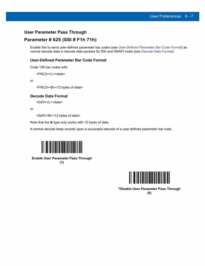
User Preferences 6 - 7
User Parameter Pass Through
Parameter # 625 (SSI # F1h 71h)Enable this to send user-defined parameter bar codes (see User-Defined Parameter Bar Code Format) as normal decode data in decode data packets for SSI and SNAPI hosts (see Decode Data Format).
User-Defined Parameter Bar Code Format Code 128 bar codes with:
<FNC3><L><data>
or
<FNC3><B><12 bytes of data>
Decode Data Format<0xf3><L><data>
or
<0xf3><B><12 bytes of data>
Note that the B type only works with 12 bytes of data.
A normal decode beep sounds upon a successful decode of a user-defined parameter bar code.
Enable User Parameter Pass Through(1)
*Disable User Parameter Pass Through(0)

6 - 8 DS457 Fixed Mount Imager Integration Guide
Beep After Good Decode
Parameter # 56 (SSI # 38h)Scan a bar code below to select whether or not the imager issues a beep signal after a good decode. If selecting Do Not Beep After Good Decode, beeper signals still occur during parameter menu scanning and to indicate error conditions.
*Beep After Good Decode(Enable)
(1)
Do Not Beep After Good Decode(Disable)
(0)
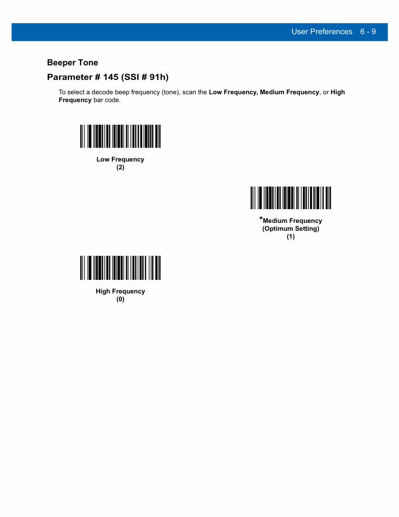
User Preferences 6 - 9
Beeper Tone
Parameter # 145 (SSI # 91h)To select a decode beep frequency (tone), scan the Low Frequency, Medium Frequency, or High Frequency bar code.
Low Frequency(2)
*Medium Frequency(Optimum Setting)
(1)
High Frequency(0)

6 - 10 DS457 Fixed Mount Imager Integration Guide
Beeper Volume
Parameter # 140 (SSI # 8Ch)To select a beeper volume, scan the Low Volume, Medium Volume, or High Volume bar code.
Suppress Power-up Beeps
Parameter # 721 (SSI # F1h D1h)Select whether or not to suppress the imager’s power-up beeps.
Low Volume(2)
Medium Volume(1)
*High Volume(0)
* Do Not Suppress Power-up Beeps(0)
Suppress Power-up Beeps(1)

User Preferences 6 - 11
Trigger Mode
Parameter # 138 (SSI # 8Ah)• Level - A trigger event activates decode processing, which continues until the trigger event ends, a valid
decode, or the decode session time-out occurs.• Presentation Mode - When the DS457 detects an object in its field of view, it triggers and attempts to
decode. The range of object detection does not vary under normal lighting conditions. This applies to decode mode only. In this mode the unit does not enter Low Power mode.
• Host - A host command issues the triggering signal. The DS457 interprets a trigger pull as a level triggering option.
• Software Trigger Only Mode - This option disables the hardware trigger so that only a host command can issue the triggering signal. This is interpreted as a level trigger option.
Level(0)
*Presentation Mode(7)
Host(8)
Software Trigger Only Mode(15)

6 - 12 DS457 Fixed Mount Imager Integration Guide
Presentation Performance Mode
Parameter # 650 (SSI # F1h 8Ah)Select one of the following Presentation Performance Mode options:
• Standard Presentation Mode is optimized for general purpose scanning, i.e., reading bar codes from standard surfaces such as paper labels or hang tags. This mode balances bar code swipe speed (the speed a bar code can pass through the field of view and still be read) and decode range (distance between the imager and the bar code) for optimal performance on standard paper-based bar codes.
• Enhanced Presentation Mode is also optimized for general purpose (paper-based) scanning but provides for a faster bar code swipe speed and shorter decode range than Standard Presentation Mode. This mode is recommended for applications requiring the highest bar code swipe speed (e.g., automated scanning) or a reduced decode range (e.g., to better match EAS deactivation range or reduce the occurrence of inadvertent reads during hands-free operation).
• Traditional Presentation Mode is optimized for applications that require frequent reading of bar codes from mobile phones or PC displays, and improves performance on large 2D symbols. This mode allows more time for the imager to analyze each bar code, improving performance on challenging bar codes such as those on a mobile phone display where the backlight has dimmed. This mode is also recommended for applications that include many truncated or poor quality bar codes. Because swipe speed is reduced, present bar codes to the imager rather than swiping them when using this mode.
NOTE To scan bar codes from mobile phones or PC displays, you must enable Mobile Phone/Display Mode on page 6-22.
*Standard Presentation Mode(2)
Enhanced Presentation Mode(0)
Traditional Presentation Mode(3)

User Preferences 6 - 13
Time Delay to Presentation Idle Mode
Parameter # 663 (SSI # F1h 97h)In Presentation Mode, this parameter sets the time the imager remains active before entering idle mode with dim illumination. The imager wakes upon presentation of a bar code or a trigger pull.
Disable(0)
1 Second(1)
10 Seconds(10)
*1 Minute(17)
5 Minutes(21)
15 Minutes(27)

6 - 14 DS457 Fixed Mount Imager Integration Guide
Time Delay to Presentation Idle Mode (continued)
30 Minutes(29)
45 Minutes(30)
1 Hour(33)
3 Hours(35)
6 Hours(38)
9 Hours(41)
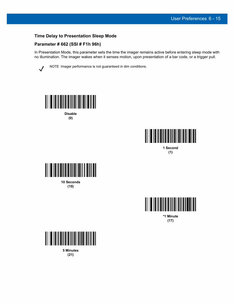
User Preferences 6 - 15
Time Delay to Presentation Sleep Mode
Parameter # 662 (SSI # F1h 96h)In Presentation Mode, this parameter sets the time the imager remains active before entering sleep mode with no illumination. The imager wakes when it senses motion, upon presentation of a bar code, or a trigger pull.
NOTE Imager performance is not guaranteed in dim conditions.
Disable(0)
1 Second(1)
10 Seconds(10)
*1 Minute(17)
5 Minutes(21)

6 - 16 DS457 Fixed Mount Imager Integration Guide
Time Delay to Presentation Sleep Mode (continued)
15 Minutes(27)
30 Minutes(29)
45 Minutes(30)
1 Hour(33)
3 Hours(35)
6 Hours(38)
9 Hours(41)

User Preferences 6 - 17
Power Mode (RS-232 Hosts Only)
Parameter # 128 (SSI # 80h)Select whether or not the imager enters Low Power consumption mode after a decode attempt. In Continuous On mode, the imager does not enter this low power state.
Time Delay to Low Power Mode
Parameter # 146 (SSI # 92h)This parameter sets the time the imager remains active after decoding. After a scan session, the imager waits this amount of time before entering Low Power mode.
Continuous On(0)
*Low Power Mode(1)
NOTE This parameter only applies when Power Mode is set to Low Power.To program a different value for this parameter than those provided here, see Using Time Delay to Low Power Mode with SSI on page 8-7.
*1 Second(17)
5 Seconds(21)

6 - 18 DS457 Fixed Mount Imager Integration Guide
Time Delay to Low Power Mode (continued)
1 Minute(33)
5 Minutes(37)
15 Minutes(43)
1 Hour(49)

User Preferences 6 - 19
Picklist Mode
Parameter # 402 (SSI # F0h 92h)Picklist mode enables the imager to decode only bar codes aligned under the center of the laser aiming pattern. Select one of the following picklist modes:
• Disabled Always - Picklist mode is always disabled.
• Enabled Always - Picklist mode is always enabled.
Decode Session Timeout
Parameter # 136 (SSI # 88h)This parameter sets the maximum time decode processing continues during a scan attempt. It is programmable in 0.1 second increments from 0.5 to 9.9 seconds. The default timeout is 9.9 seconds.
To set a Decode Session Timeout, scan the bar code below. Next, scan two numeric bar codes from Appendix D, Numeric Bar Codes that correspond to the desired on time. Provide a leading zero for single digit numbers. For example, to set a Decode Session Timeout of 0.5 seconds, scan the bar code below, then scan the 0 and 5 bar codes. To correct an error or change the selection, scan Cancel on page D-3.
NOTE With Picklist Mode enabled, the decode aiming pattern turns on even when the Decode Aiming Pattern on page 7-6 is disabled.
Picklist mode does not apply to OCR reading.
*Disabled Always(0)
Enabled Always(2)
Decode Session Timeout

6 - 20 DS457 Fixed Mount Imager Integration Guide
Timeout Between Decodes, Same Symbol
Parameter # 137 (SSI # 89h)Use this option in presentation mode to prevent multiple reads of a symbol left in the DS457’s field of view. The timeout begins when you remove the symbol from the field of view.
To select the timeout between decodes for the same symbol, available in 0.1 second increments from 0.0 to 9.9 seconds, scan the bar code below, then scan two numeric bar codes from Appendix D, Numeric Bar Codes that correspond to the desired interval. The default interval is 0.6 seconds.
Continuous Bar Code Read
Parameter # 649 (SSI # F1h 89h)Select Enable to allow decode processing to continue until the trigger event ends or the decode session time-out occurs. User indications occur upon decoding each bar code. Select Disable to end decode processing upon a valid decode as well. This mode does not apply to presentation mode.
Timeout Between Decodes, Same Symbol
NOTE Zebra strongly recommends enabling Picklist Mode on page 6-19 with this feature. Disabling Picklist Mode can cause accidental decodes when more than one bar code is in the imaging engine's field of view.
*Disable Continuous Bar Code Read(0)
Enable Continuous Bar Code Read(1)

User Preferences 6 - 21
Unique Bar Code Reporting
Parameter # 723 (SSI # F1h D3h)Enable this to report only unique bar codes while the trigger is pressed. This option only applies when Continuous Bar Code Read is enabled.
Mirrored Image
Parameter # 624 (SSI # F1h 70h)Enable this to scan images in reverse, or mirrored, as if seen through a mirror. This mode is useful in applications requiring scanning through a mirror and using symbologies that do not decode in reverse.
Enabling this mode when using snapshot, video, or video viewfinder modes transmits images as mirrored images.
Disable Unique Bar Code Reporting(0)
*Enable Unique Bar Code Reporting(1)
*Disable Mirrored Image(0)
Enable Mirrored Image(1)
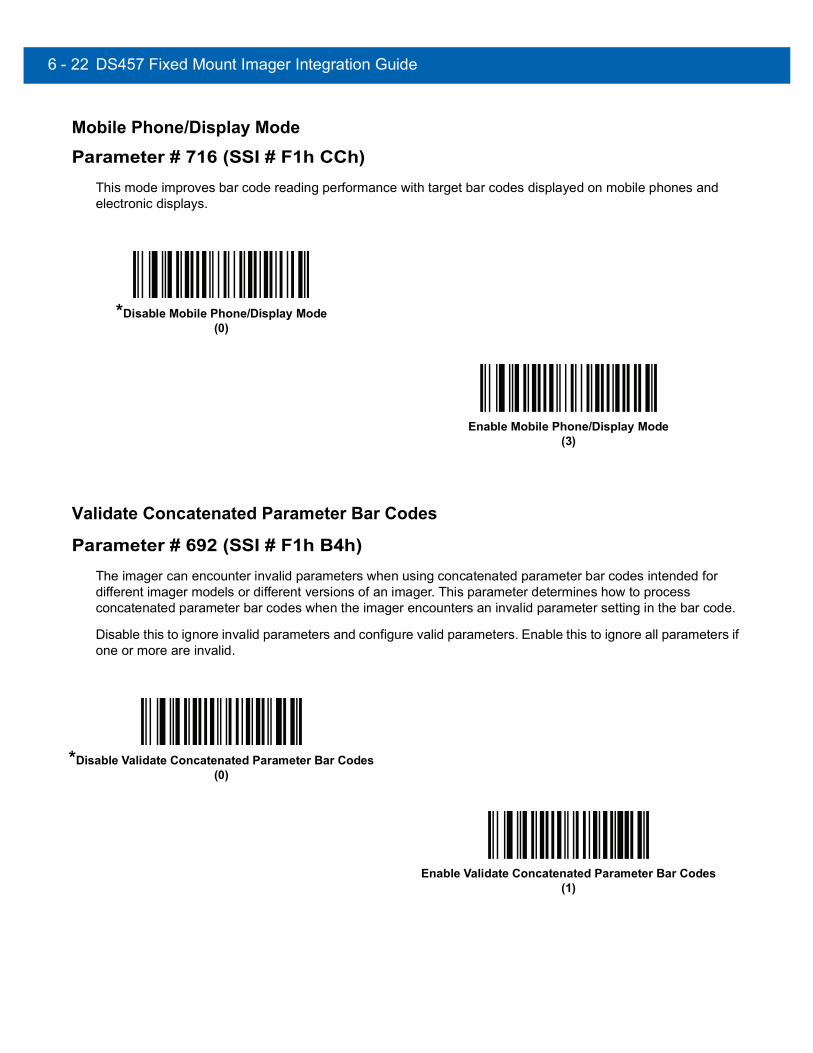
6 - 22 DS457 Fixed Mount Imager Integration Guide
Mobile Phone/Display Mode
Parameter # 716 (SSI # F1h CCh)This mode improves bar code reading performance with target bar codes displayed on mobile phones and electronic displays.
Validate Concatenated Parameter Bar Codes
Parameter # 692 (SSI # F1h B4h)The imager can encounter invalid parameters when using concatenated parameter bar codes intended for different imager models or different versions of an imager. This parameter determines how to process concatenated parameter bar codes when the imager encounters an invalid parameter setting in the bar code.
Disable this to ignore invalid parameters and configure valid parameters. Enable this to ignore all parameters if one or more are invalid.
*Disable Mobile Phone/Display Mode(0)
Enable Mobile Phone/Display Mode(3)
*Disable Validate Concatenated Parameter Bar Codes(0)
Enable Validate Concatenated Parameter Bar Codes(1)

User Preferences 6 - 23
PDF Prioritization
Parameter # 719 (SSI # F1h CFh)Enable this feature to delay decoding a 1D bar code (Code 128 of 8 to 25 characters length) by the value specified in PDF Prioritization Timeout. During that time the imager attempts to decode a PDF417 symbol (e.g., on a US driver's license), and if successful reports this only. If it does not decode (can not find) a PDF417 symbol, it reports the 1D symbol after the timeout. The 1D symbol must be in the device’s field of view for the imager to report it. This parameter does not affect decoding other symbologies.
PDF Prioritization Timeout
Parameter # 720 (SSI # F1h D0h)When PDF Prioritization is enabled, this timeout specifies how long the imager attempts to decode a PDF417 symbol before reporting the 1D bar code in the field of view.
Scan the following bar code, then scan four digits from Appendix D, Numeric Bar Codes that specify the timeout in milliseconds. For example, to enter 200 ms, scan the following bar code, then scan 0200. The range is 0 to 5000 ms, and the default is 400 ms.
*Disable PDF Prioritization(0)
Enable PDF Prioritization(1)
PDF Prioritization Timeout
NOTE PDF Prioritization Timeout must be at least one second lower than the Decode Session Timeout.

6 - 24 DS457 Fixed Mount Imager Integration Guide
Multicode Mode
Parameter # 677 (SSI # F1h, A5h)Enable this parameter to allow multiple bar codes to decode upon one trigger event based on the programmed multicode expression. The imager reports a successful decode and provides user indication only if it decodes all bar codes indicated by the multicode expression, otherwise the decode fails. Bar codes are transmitted in the order defined in the multicode expression. Disable this to operate in normal decode mode.
This mode operates in Level trigger mode only. Also disable Continuous Bar Code Read. If you enable this mode, always orient the imager at the same distance and angle (perpendicular).
NOTE DS457-DP does not support Multicode Mode.
*Disable Multicode Mode(0)
Enable Multicode Mode(1)

User Preferences 6 - 25
Multicode Expression
Parameter # 661 (SSI # F1h, 95h)Use this feature to program a multicode expression for Multicode Mode (grid method). The default is 1, which indicates any bar code.
To set the multicode expression:
1. Scan the bar code below.2. Scan bar codes from the Alphanumeric Keyboard in the Advanced Data Formatting Programmer Guide. 3. Scan End of Message in the Advanced Data Formatting Programmer Guide.
Multicode Expression Syntax: [n] [Element 1]; [Element 2 ]; ... [Element n];Where n is the number of elements in the overall expression.
The multicode expression describes the bar code(s) that the imager can expect to find in an image. Each element represents one bar code in the DS457's field of view. The order of elements in the expression is the order in which bar code data from each element transmits to the host. Elements are defined using one or more of the following methods:
By Region. This type of element limits decoding to a specific area within the DS457's field of view. Region coordinates are defined as the top left and bottom right corners of the region, expressed in percentages of the field of view. These can range from 0% to 100%, or 0x00 to 0x64 in hex, for both horizontal and vertical axes. A region element is constructed as:
[R] [4] [Top, Left] [Bottom, Right]
Where:
• [R] is the character R
• [4] is 0x04, indicating there are four bytes thereafter to describe the region
• [Top, Left] are two values representing the top left corner of the region
• [Bottom, Right] are two values representing the bottom right corner of the region
Note that the top of the field of view used for multicode expressions is the topmost part of the field of view when the DS457's chassis rests on a horizontal surface.
NOTE DS457-DP does not support this parameter.
Multicode Expression

6 - 26 DS457 Fixed Mount Imager Integration Guide
By Code Type. An element can specify a specific bar code symbology to find and decode somewhere in the field of view. A code type element is constructed as:
[C] [2] [Code Type]
Where: • [C] is the character C• [2] is 0x02, indicating there are two bytes thereafter to describe the code type• [Code Type] is the desired symbology's parameter number (see Chapter 12, Symbologies). For
single-byte parameter numbers, extend the value to two bytes by adding 00 before the parameter number.
NotesWhen defining multicode expressions consider the following:
• Use the Code Type specifier if there are bar codes of more than one code type in view.
• Always use the Region specifier when there are multiple bar codes of the same code type.
• When transmission order is important (the first element in the expression transmits first), use either type to define the order.
• When there are unwanted bar codes in view, filter them out in one of two ways:• Use Code Type to specify only the target bar codes.• Use Region to identify only the target bar codes.
• If the expression does not contain a Region specifier, scanning angle and distance do not matter. If you specify a region you must scan in a fixed orientation and at a fixed distance. Because of this, it is preferable to use the Code Type specifier rather than the Region specifier.
• When defining regions:• Defining a region much larger than the bar code improves tolerance to scan distance and angle, but
can cause a decode of a nearby bar code instead of the target bar code. Therefore, for best performance define larger regions when only a few bar codes are in view and those in view are widely separated.
• Defining a region close to (or smaller than) the target bar code improves the probability of decoding this bar code rather than one nearby, but scan distance and angle must be more accurate. Therefore, for best performance define small regions when many bar codes are in view or those in view are close together.
• Use Region elements to improve decode speeds by reducing the image area to search for the target bar code.
• Specifying Code Type may also improve decode speeds for some code types.
• Although you can scan parameter bar codes when multicode mode is enabled, be aware of the following: If the multicode expression defined a region(s), to scan a parameter bar code you must position the bar code within the first region defined in the expression. In some cases, this first region is not the center of the image and aiming at the parameter bar code does not result in a successful decode.
The following examples show the multicode expressions in both hex and decimal formats, however in the sample figures the values are decimal. Be sure to use the correct base numbering system when creating an expression. A region specified as 0x00 0x00 0x64 0x32 represents a region with coordinates of Top-Left (0,0) and Bottom Right (100,50).

User Preferences 6 - 27
Example 1
To decode one Code 128 bar code anywhere in the image (even when bar codes of other types are in view), as in Figure 6-1, program the expression as follows:
The expression in decimal is (formatted for readability):
1 C 2 0 8 ;
To program the expression via scanning parameters the sequence is (spaces are for readability):
[MultiCode-Expression] 01 C 02 00 08 ; [End Of Message]
To program the expression via host command (SSI/SNAPI) the sequence is:
0x01 0x43 0x02 0x00 0x08 0x3b
For more information on this method, see Programming a Multicode Expression via SSI Command on page 6-31.
Figure 6-1 Multicode Expression Example 1
0 12345 67890 5
50%
0%
100%
0% 50% 100%
PDF417 Code
Code 128 Code
UPC-A Code

6 - 28 DS457 Fixed Mount Imager Integration Guide
Example 2a
To decode a Code128 (Code Type=8) on the top half of the image and a PDF417 (Code Type=15) on the bottom half of the image, as in Figure 6-2, program the expression as follows:
The expression in decimal is (formatted for readability):2 C 2 0 8 R 4 0 0 100 50 ; C 2 0 15 R 4 0 50 100 100 ;
To program the expression via scanning parameters the sequence is:[MultiCode-Expression] 02 C 02 00 08 R 04 00 00 64 32 ; C 02 00 0F R 04 00 32 64 64 ; [End Of Message]
To program the expression via host command (SSI/SNAPI) the sequence is:0x02 0x43 0x02 0x00 0x08 0x52 0x04 0x00 0x00 0x64 0x32 0x3B 0x43 0x02 0x00 0x0F 0x52 0x04 0x00 0x32 0x64 0x64 0x3B
For more information on this method, see Programming a Multicode Expression via SSI Command on page 6-31.
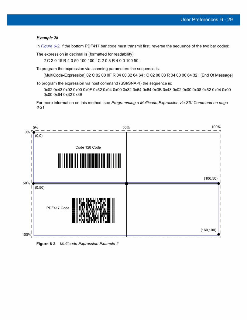
User Preferences 6 - 29
Example 2b
In Figure 6-2, if the bottom PDF417 bar code must transmit first, reverse the sequence of the two bar codes:
The expression in decimal is (formatted for readability):2 C 2 0 15 R 4 0 50 100 100 ; C 2 0 8 R 4 0 0 100 50 ;
To program the expression via scanning parameters the sequence is:[MultiCode-Expression] 02 C 02 00 0F R 04 00 32 64 64 ; C 02 00 08 R 04 00 00 64 32 ; [End Of Message]
To program the expression via host command (SSI/SNAPI) the sequence is:0x02 0x43 0x02 0x00 0x0F 0x52 0x04 0x00 0x32 0x64 0x64 0x3B 0x43 0x02 0x00 0x08 0x52 0x04 0x00 0x00 0x64 0x32 0x3B
For more information on this method, see Programming a Multicode Expression via SSI Command on page 6-31.
Figure 6-2 Multicode Expression Example 2
PDF417 Code
(0,0)
Code 128 Code
(0,50)
(160,100)
(100,50)50%
0%
100%
0% 50% 100%

6 - 30 DS457 Fixed Mount Imager Integration Guide
Example 3
To decode the set of three bar codes while excluding the center Code 128 bar code, as in Figure 6-3, the expression is:
The expression in decimal is (formatted for readability):
3 C 2 0 15 R 4 0 0 50 50 ; C 2 [F0 24] R 4 70 0 100 40 ; C 2 0 8 R 4 65 60 100 100 ;
To program the expression via scanning parameters the sequence is:
[MultiCode-Expression] 03 C 02 00 0F R 04 00 00 32 32 ; C 02 F0 24 R 04 46 00 64 28 ; C 02 00 08 R 04 41 3C 64 64 ; [End Of Message]
To program the expression via host command (SSI/SNAPI) the sequence is:
0x03 0x43 0x02 0x00 0x0F 0x52 0x04 0x00 0x00 0x32 0x32 0x3B 0x43 0x02 0xF0 0x24 0x52 0x04 0x46 0x00 0x64 0x28 0x3B 0x43 0x02 0x00 0x08 0x52 0x04 0x41 0x3C 0x64 0x64 0x3B
For more information on this method, see Programming a Multicode Expression via SSI Command on page 6-31.
Figure 6-3 Multicode Expression Example 3
40%
65%
40%
40%
PDF417 Code
Code 128 Code
Data Matrix Code
Code 128 Code
70%
60%
(70,0)
(100,40)
(100,100)
(0,0)
(40,40)
(65,60)
50%
0%
100%
0% 50% 100%

User Preferences 6 - 31
Programming a Multicode Expression via SSI CommandThe following example describes how to program a Multicode expression via SSI within a Remote Scanner Management (RSM) command.
SSI Transaction Sequences
Before sending the Multicode expression transaction (a command/response pair), perform the following initialization transaction (command and response). This initialization transaction is required only once upon each imager power up:
Command (to imager): 0A 80 04 00 00 06 20 00 00 FF FE 4DResponse (from imager): 0C 80 00 00 00 08 20 00 00 F0 00 F0 FD 6C
Next, program the Multicode Expression using the following basic transaction format.
Command (to imager): 17 80 04 00 00 13 06 00 02 95 41 00 42 00 06 00 [Multicode Expression in Hex] FD A3Response (from imager): 08 80 00 00 00 04 06 00 FF 6E
For full details on structuring Multicode expression commands, see Figure 6-4.
Legend for Figure 6-4
• All values in the table are hex, unless followed by a d which indicates decimal.
• Shaded fields represent values that change for different Multicode expressions. Unshaded fields are fixed and are constant for all expressions.
• N: The length of the Multicode expression in bytes. Using Example 1, N = 6 decimal, 0x06 hex.
• Len1: N+17. Using Example 1, Len1 = 23 decimal, 0x17 hex.
• Len2: N+13. Using Example 1, Len2 = 19 decimal, 0x13 hex.
• Op: Command persistence.• 0x06 stores the Multicode expression in non-volatile memory. The command persists through power
cycling.or
• 0x05 stores the Multicode expression in RAM. The command is lost when power is removed from the imager.
• Len4: Same value as N. Using Example 1, Len4 = 6 decimal, 0x06 hex.
• Checksum: 2's compliment checksum of bytes in the SSI Header and SSI Data. Sum all bytes, truncate to a 2 byte value, subtract this value from 0x10000; the resulting number is the 2 byte checksum. Using Example 1 the checksum is FDA3.
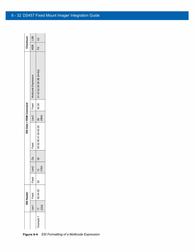
6 - 32 DS457 Fixed Mount Imager Integration Guide
Figure 6-4 SSI Formatting of a Multicode Expression
SSI H
eade
rSS
I Dat
a =
RSM
Com
man
dCh
ecks
um
Len1
Fixe
dFi
xed
Len2
Op
Fixe
dLe
n3Fi
xed
Mul
ticod
e Ex
pres
sion
MSB
LSB
Exam
ple
117 (2
3d)
80 0
4 00
0013 (1
9d)
0600
02
95 4
1 00
42
0006 (0
6d)
00 0
001
43
02 0
0 08
3B
(N=6
d)FD
A3

User Preferences 6 - 33
Multicode Mode Concatenation
Parameter # 717 (SSI # F1h, CDh)Enable this parameter to transmit multiple decoded bar codes, as specified by the Multicode Expression, as one bar code. Use the Multicode Concatenation Symbology parameter to specify how the concatenated bar codes transmit.
Disable this to transmit decoded bar codes separately.
NOTE When using Multicode Mode Concatenation, disable Transmit Code ID Character on page 6-37 and check digits.
DS457-DP does not support this parameter.
Enable Multicode Mode Concatenation(1)
*Disable Multicode Mode Concatenation(0)
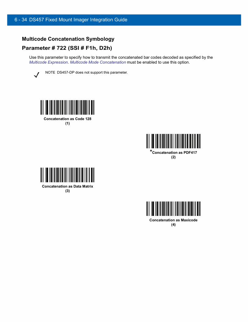
6 - 34 DS457 Fixed Mount Imager Integration Guide
Multicode Concatenation Symbology
Parameter # 722 (SSI # F1h, D2h)Use this parameter to specify how to transmit the concatenated bar codes decoded as specified by the Multicode Expression. Multicode Mode Concatenation must be enabled to use this option.
NOTE DS457-DP does not support this parameter.
Concatenation as Code 128(1)
*Concatenation as PDF417(2)
Concatenation as Data Matrix(3)
Concatenation as Maxicode(4)

User Preferences 6 - 35
Multicode Troubleshooting
Troubleshooting Multicode Expression ProgrammingUse the following suggestions if encountering problems programming a multicode expression:
• Ensure the expression is valid. Invalid expressions are rejected during programming. When an expression is rejected the previous expression remains intact. If after programming the expression the imager can still decode any bar code, the expression was possibly rejected.
• When programming the multicode expression via parameter bar code, the DS457 generates beeps. If any of the following beeps do not sound during programming, an error occurred (see Table 3-1 on page 3-4 for error indicators):• Scanning the Multicode Expression bar code produces a two-tone (same pitch) beep. • Scanning each value of the expression produces a two-tone (same pitch) beep. • Scanning the End Of Message bar code produces a four-tone (high-low-high-low) beep.
• Check the expression for syntax errors.
• Try programming a simple expression to ensure the syntax is correct. See Examples of Simple Multicode Expressions.
• Review Notes on page 6-26 for additional hints.
Troubleshooting Multicode Mode Scanning and Decoding Use the following suggestions if encountering problems using multicode mode:
• If the DS457 appears to decode any single bar code instead of the intended multiple bar codes, ensure you enabled Multicode Mode on page 6-24. Programming the multicode expression does not enable multicode mode.
• When specifying Region, ensure: • Coordinates are within range the 0-100 decimal (or 0x00 - 0x64 hexadecimal).• Top, Left is above Bottom, Right. Top, Left is 0,0 (0x00, 0x00 hexadecimal), and Bottom, Right is
100,100 (0x64, 0x64 hexadecimal). • Regions for two or more bar codes do not overlap.
• When specifying Code Type ensure the DS457 supports the code type. Try decoding a single bar code without using multicode. If it does not decode try enabling the bar code type. See Chapter 12, Symbologies.
• Experiment with simpler expressions, then add to it until you discover the source of the error. For example try the simplest expression (see Examples of Simple Multicode Expressions) and make sure you can scan a single bar code. If so, extend the expression by adding a second bar code, specifying a region, or specifying the code type. Verify that the DS457 can decode this new expression. Continue adding to the expression until it fails to decode as expected, indicating the source of the error.
• Review Notes on page 6-26 for additional hints.

6 - 36 DS457 Fixed Mount Imager Integration Guide
Examples of Simple Multicode Expressions
The simplest multicode expression is:
• One bar code of any type, anywhere in the image.
• To program this use: [MultiCode-Expression] 01 ; [End Of Message]
Another simple multicode expression is:
• One Code 128 bar code, anywhere in the image.
• To program this use: [MultiCode-Expression] 01 C 02 00 08 ; [End Of Message]

User Preferences 6 - 37
Miscellaneous Parameters
Transmit Code ID Character
Parameter # 45 (SSI # 2Dh)A Code ID character identifies the code type of a scanned bar code. This is useful when the imager is decoding more than one code type. In addition to any single character prefix already selected, the Code ID character is inserted between the prefix and the decoded symbol.
Select no Code ID character, a Symbol Code ID character, or an AIM Code ID character. For Code ID Characters, see Code Identifiers on page B-1.
Symbol Code ID Character(2)
AIM Code ID Character(1)
*None(0)

6 - 38 DS457 Fixed Mount Imager Integration Guide
Prefix/Suffix Values
Parameter # Prefix = 105, Suffix1 = 104, Suffix2 = 106Key Category Parameter # Prefix = 63h, Suffix1 = 62h, Suffix2 = 64hDecimal Value Parameter # Prefix = 69h, Suffix1 = 68h, Suffix2 = 6AhA prefix and/or one or two suffixes can be appended to scan data for use in data editing. To set a value for a prefix or suffix, scan the prefix or suffix bar code below, then scan a four-digit number (i.e., four bar codes from Appendix D, Numeric Bar Codes) that corresponds to that value. The first digit defines the key category (type of character to send) and is stored in the key category parameter. The remaining three digits define the value of the character and are stored in the decimal value parameter. Be sure to use both key category and decimal value parameters to define the prefix/suffix value.
See Table E-1 on page E-1 for the four-digit code values. To correct an error or change a selection, scan Cancel on page D-3.
NOTE When using the imager with an SSI or SNAPI host, only a key category value of 1 is valid. All other values are ignored.
To send a Prefix or Suffix with bar code data, first enable the format in which they are sent by setting the Scan Data Transmission Format on page 6-39.
Scan Prefix(7)
Scan Suffix 1(6)
Scan Suffix 2(8)

User Preferences 6 - 39
Scan Data Transmission Format
Parameter # 235 (SSI # EBh)To change the scan data format, scan one of the following eight bar codes corresponding to the desired format.
To set values for the prefix and/or suffix, see Prefix/Suffix Values on page 6-38.
NOTE If using this parameter do not use ADF rules to set the prefix/suffix.
*Data As Is(0)
<DATA> <SUFFIX 1>(1)
<DATA> <SUFFIX 2>(2)
<DATA> <SUFFIX 1> <SUFFIX 2>(3)
<PREFIX> <DATA >(4)

6 - 40 DS457 Fixed Mount Imager Integration Guide
FN1 Substitution Values
Key Category Parameter # 103 (SSI # 67h)
Decimal Value Parameter # 109 (SSI # 6Dh)The Wedge and USB HID Keyboard hosts support a FN1 Substitution feature. When enabled any FN1 character (0x1b) in an EAN128 bar code is substituted with a value. This value defaults to 7013 (Enter Key).
When using host commands to set the FN1 substitution value, set the key category parameter to 1, then set the 3-digit keystroke value. See the ASCII Character Set table for the currently installed host interface for the desired value.To select a FN1 substitution value via bar code menus:
1. Scan the bar code below.
2. Look up the keystroke desired for FN1 Substitution in the ASCII Character Set table for the currently installed host interface. Enter the 4-digit ASCII Value by scanning each digit in Appendix D, Numeric Bar Codes.
To correct an error or change the selection, scan Cancel.To enable FN1 substitution for USB HID keyboard, scan the Enable FN1 Substitution bar code on page 10-11.
Scan Data Transmission Format (continued)
<PREFIX> <DATA> <SUFFIX 1>(5)
<PREFIX> <DATA> <SUFFIX 2>(6)
<PREFIX> <DATA> <SUFFIX 1> <SUFFIX 2>(7)
Set FN1 Substitution Value
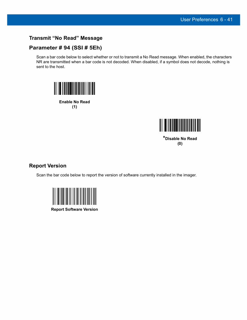
User Preferences 6 - 41
Transmit “No Read” Message
Parameter # 94 (SSI # 5Eh)Scan a bar code below to select whether or not to transmit a No Read message. When enabled, the characters NR are transmitted when a bar code is not decoded. When disabled, if a symbol does not decode, nothing is sent to the host.
Report VersionScan the bar code below to report the version of software currently installed in the imager.
Enable No Read(1)
*Disable No Read(0)
Report Software Version

6 - 42 DS457 Fixed Mount Imager Integration Guide

CHAPTER 7IMAGER PREFERENCES
IntroductionThis chapter describes imager preference features and provides the programming bar codes for selecting these features.
The imager ships with the settings shown in the Imager Preferences Default Table on page 7-2 (also see Appendix A, Standard Default Parameters for all host and miscellaneous defaults). If the default values suit requirements, programming is not necessary.
There are two ways to change a parameter value:
• Scan the appropriate bar codes in this guide. These new values replace the standard default values in memory.
• For SSI and USB SNAPI hosts, send a “parameter send” command from the host system. Hexadecimal parameter numbers appear in this chapter below the parameter title, and options appear in parenthesis beneath the accompanying bar codes. See the Simple Serial Interface (SSI) Programmer’s Guide for detailed instructions for changing parameter values using this method.
Select a host type (see each host chapter for specific host information) after the power-up beep signal activates. This is only necessary upon the first power-up when connected to a new host.
To return all features to default values, scan the Set Default Parameter on page 6-5. Throughout the programming bar code menus, asterisks (*) indicate default values.
NOTE Most computer monitors allow scanning the bar codes directly on the screen. When scanning from the screen, be sure to set the document magnification to a level where you can see the bar code clearly, and bars and/or spaces are not merging.
Feature/Option
* Indicates default *Enable Decode Aiming Pattern(2) Option decimal value for
programming

7 - 2 DS457 Fixed Mount Imager Integration Guide
Scanning Sequence ExamplesIn most cases scanning one bar code sets the parameter value. For example, to disable the decode aiming pattern, scan the Disable Decode Aiming Pattern bar code listed under Decode Aiming Pattern on page 7-6. For systems that use a beeper and LED, a fast warble beep sounds and the LED lights, signifying a successful parameter entry.
Other parameters, such as Crop to Pixel Address, require scanning several bar codes. See these parameter descriptions for this procedure.
Errors While ScanningUnless otherwise specified, to correct an error during a scanning sequence, just re-scan the correct parameter.
Imager Preferences Parameter DefaultsTable 7-1 lists defaults for imager preferences parameters. To change any option, scan the appropriate bar code(s) provided in Imager Preferences on page 7-4.
NOTE See Appendix A, Standard Default Parameters for all user preferences, hosts, symbologies, and miscellaneous default parameters
Table 7-1 Imager Preferences Default Table
Parameter Parameter Number SSI Number Default Page
Number
Imaging Options
Decoding Autoexposure 297 F0h 29h Enable 7-5
Decoding Illumination 298 F0h 2Ah Enable 7-6
Decode Aiming Pattern 306 F0h 32h Enable 7-6
Aim Brightness 668 F1h 9Ch 0 7-7
Illumination Brightness 669 F1h 9Dh 10 7-7
Low Light Enhancement 612 F1h 64h Disable 7-8
Power Up Light in Presentation Mode 1198 F8h 04h AEh Disable 7-8
Presentation Mode Field of View 609 F1h 61h Default (Reduced) 7-9
Frame Rate 674 F1h A2h Auto 7-10
Image Capture Autoexposure 360 F0h 68h Enable 7-12
Image Capture Illumination 361 F0h 69h Enable 7-12
Fixed Gain 568 F1h 38h 50 7-13
Exposure Time 567 F4h F1h 37h 100 (10 ms) 7-13
Snapshot Mode Timeout 323 F0h 43h 0 (30 seconds) 7-14

Imager Preferences 7 - 3
Snapshot Aiming Pattern 300 F0h 2Ch Enable 7-14
Presentation Snapshot by Motion 647 F1h 87h Disable 7-15
Continuous Snapshot 648 F1h 88h Disable 7-15
Image Cropping 301 F0h 2Dh Disable 7-16
Crop to Pixel Addresses 315, 316, 317, 318
F4h F0h 3Bh; F4h F0h 3Ch; F4h F0h 3Dh; F4h F0h 3Eh
0 top, 0 left, 479 bottom, 751 right
7-17
Image Resolution 302 F0h 2Eh Full 7-18
Image Brightness (Target White) 390 F0h 86h 180 7-19
Image File Format Selection 304 F0h 30h JPEG 7-20
JPEG Image Options 299 F0h 2Bh Quality 7-20
JPEG Quality Value 305 F0h 31h 65 7-21
JPEG Size Value 561 F1h 31h 160 (164K) 7-21
Image File Meta Data 693 F1h B5h Disable 7-22
Image Enhancement 564 F1h 34h Off 7-22
Image Edge Sharpening 664 F1h 98h Low 7-23
Image Contrast Enhancement 666 F1h 9Ah Off 7-24
Image Rotation 665 F1h 99h 0 7-26
Bits per Pixel (BPP) 303 F0h 2Fh 8 BPP 7-27
Signature Capture 93 5Dh Disable 7-28
Signature Capture Image File Format Selection
313 F0h 39h JPEG 7-29
Signature Capture Bits per Pixel (BPP) 314 F0h 3Ah 8 BPP 7-30
Signature Capture Width 366 F4h F0h 6Eh 400 7-30
Signature Capture Height 367 F4h F0h 6Fh 100 7-31
Signature Capture JPEG Quality 421 F0h A5h 65 7-31
Video Mode Format Selector 916 F2h 94h JPEG 7-31
Video View Finder 324 F0h 44h Disable 7-32
Target Video Frame Size 328 F0h 48h 2200 bytes 7-33
Video View Finder Image Size 329 F0h 49h 1700 bytes 7-33
Video Resolution 667 F1h 9Bh 1/4 resolution 7-34
Table 7-1 Imager Preferences Default Table (Continued)
Parameter Parameter Number SSI Number Default Page
Number

7 - 4 DS457 Fixed Mount Imager Integration Guide
Imager PreferencesThe parameters in this chapter control image capture characteristics. Image capture occurs in all modes of operation, including decode, video, and snapshot.
Operational ModesThe imager has three modes of operation:
• Decode Mode
• Snapshot Mode• Snapshot with Viewfinder Mode
• Video Mode.
Decode ModeBy default, upon a trigger event, the imager attempts to locate and decode bar codes within its field of view. The imager remains in this mode as long as the trigger is active, until it decodes a bar code, or it reaches the Decode Session Timeout on page 6-19.
Snapshot ModeUse Snapshot Mode to capture a high-quality image and transmit it to the host. To temporarily enter this mode scan the Snapshot Mode bar code. While in this mode the imager blinks the green LED at 1-second intervals to indicate it is not in standard operating (decode) mode.
In Snapshot Mode, the DS457 laser aiming pattern highlights the area to capture in the image. The next trigger event instructs the imager to capture a high quality image and transmit it to the host. A short time may pass (less than 2 seconds) between trigger activation and image capture as the imager adjusts to the lighting conditions. Hold the imager steady until image capture, denoted by a single beep.
If a trigger event does not occur within the Snapshot Mode Timeout period, the imager returns to Decode Mode. Use Snapshot Mode Timeout on page 7-14 to adjust this timeout period. The default timeout period is 30 seconds.
To disable the laser aiming pattern during Snapshot Mode, see Snapshot Aiming Pattern on page 7-14.
Use Video View Finder on page 7-32 to enable Snapshot with Viewfinder Mode. In this mode the imager behaves as a video camera until the trigger activates, at which time a Snapshot occurs as described above.
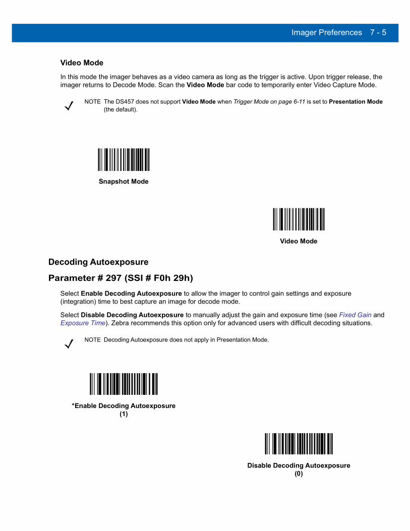
Imager Preferences 7 - 5
Video ModeIn this mode the imager behaves as a video camera as long as the trigger is active. Upon trigger release, the imager returns to Decode Mode. Scan the Video Mode bar code to temporarily enter Video Capture Mode.
Decoding Autoexposure
Parameter # 297 (SSI # F0h 29h)Select Enable Decoding Autoexposure to allow the imager to control gain settings and exposure (integration) time to best capture an image for decode mode.
Select Disable Decoding Autoexposure to manually adjust the gain and exposure time (see Fixed Gain and Exposure Time). Zebra recommends this option only for advanced users with difficult decoding situations.
NOTE The DS457 does not support Video Mode when Trigger Mode on page 6-11 is set to Presentation Mode (the default).
Snapshot Mode
Video Mode
NOTE Decoding Autoexposure does not apply in Presentation Mode.
*Enable Decoding Autoexposure(1)
Disable Decoding Autoexposure(0)
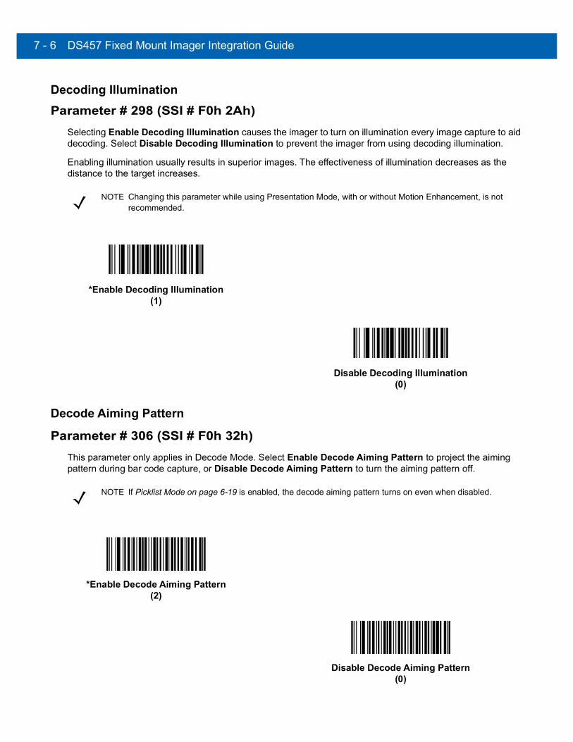
7 - 6 DS457 Fixed Mount Imager Integration Guide
Decoding Illumination
Parameter # 298 (SSI # F0h 2Ah)Selecting Enable Decoding Illumination causes the imager to turn on illumination every image capture to aid decoding. Select Disable Decoding Illumination to prevent the imager from using decoding illumination.
Enabling illumination usually results in superior images. The effectiveness of illumination decreases as the distance to the target increases.
Decode Aiming Pattern
Parameter # 306 (SSI # F0h 32h)This parameter only applies in Decode Mode. Select Enable Decode Aiming Pattern to project the aiming pattern during bar code capture, or Disable Decode Aiming Pattern to turn the aiming pattern off.
NOTE Changing this parameter while using Presentation Mode, with or without Motion Enhancement, is not recommended.
*Enable Decoding Illumination(1)
Disable Decoding Illumination(0)
NOTE If Picklist Mode on page 6-19 is enabled, the decode aiming pattern turns on even when disabled.
*Enable Decode Aiming Pattern(2)
Disable Decode Aiming Pattern(0)
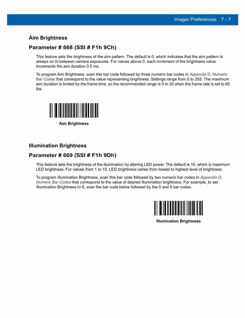
Imager Preferences 7 - 7
Aim Brightness
Parameter # 668 (SSI # F1h 9Ch)This feature sets the brightness of the aim pattern. The default is 0, which indicates that the aim pattern is always on in between camera exposures. For values above 0, each increment of the brightness value increments the aim duration 0.5 ms.
To program Aim Brightness, scan this bar code followed by three numeric bar codes in Appendix D, Numeric Bar Codes that correspond to the value representing brightness. Settings range from 0 to 255. The maximum aim duration is limited by the frame time, so the recommended range is 0 to 30 when the frame rate is set to 60 fps.
Illumination Brightness
Parameter # 669 (SSI # F1h 9Dh)This feature sets the brightness of the illumination by altering LED power. The default is 10, which is maximum LED brightness. For values from 1 to 10, LED brightness varies from lowest to highest level of brightness.
To program Illumination Brightness, scan this bar code followed by two numeric bar codes in Appendix D, Numeric Bar Codes that correspond to the value of desired illumination brightness. For example, to set Illumination Brightness to 6, scan the bar code below followed by the 0 and 6 bar codes.
Aim Brightness
Illumination Brightness

7 - 8 DS457 Fixed Mount Imager Integration Guide
Low Light Enhancement
Parameter # 612 (SSI # F1h 64h)In Presentation Mode, selecting Enable Low Light Enhancement causes illumination to remain on at low power in low lighting conditions. When the imager detects an object in its field of view, it turns on illumination full power. Select Disable Low Light Enhancement to prevent illumination from remaining on under low lighting conditions
Power Up Light in Presentation Mode
Parameter # 1198 (SSI # F8h 04h AEh)Enable this option to turn on full illumination upon power-up when in presentation mode or transitioning to presentation mode. If Low Light Enhancement is also enabled, illumination turns on at low power in presentation mode. If both are disabled, illumination remains off until motion is detected.
Enable Low Light Enhancement(1)
*Disable Low Light Enhancement(0)
Enable Power Up Light in Presentation Mode(1)
*Disable Power Up Light in Presentation Mode(0)

Imager Preferences 7 - 9
Presentation Mode Field of View
Parameter # 609 (SSI # F1h 61h)In Presentation Mode, by default the imager searches for a bar code in a smaller region around the aiming pattern’s center cross to speed search time.
To use a full field of view, scan Presentation Mode Full Field of View. This allows the imager to search the larger area of the aiming pattern.
*Presentation Mode Default Field of View(1)
Presentation Mode Full Field of View(2)

7 - 10 DS457 Fixed Mount Imager Integration Guide
Frame Rate
Parameter # 674 (SSI # F1h A2h)Select an option to control the rate at which frames are captured and transmitted. When capturing images, using lower frame rates can improve image brightness.
Settings for frame rate are:
• Auto - The imager controls the frame rate and changes dynamically based on the mode of operation to provide optimal performance.
• 60 fps - The frame rate is fixed at 60 frames per second• 55 fps - The frame rate is fixed at 55 frames per second• 50 fps - The frame rate is fixed at 50 frames per second• 45 fps - The frame rate is fixed at 45 frames per second• 40 fps - The frame rate is fixed at 40 frames per second• 30 fps - The frame rate is fixed at 30 frames per second• 20 fps - The frame rate is fixed at 20 frames per second• 15 fps - The frame rate is fixed at 15 frames per second• 10 fps - The frame rate is fixed at 10 frames per second
NOTE The aiming pattern appears to blink when the frame rate is 30 frames per second (fps) or lower.
*Auto(0)
60 fps(1)
55 fps(5)
50 fps(6)
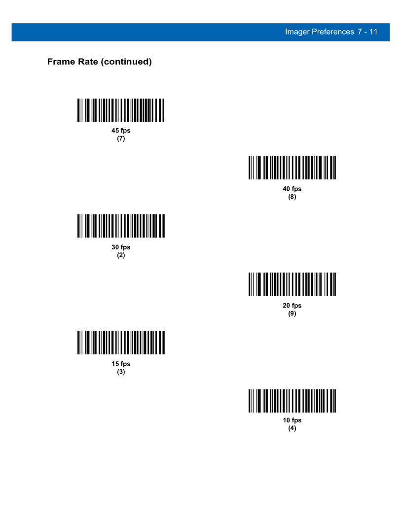
Imager Preferences 7 - 11
Frame Rate (continued)
45 fps(7)
40 fps(8)
30 fps(2)
20 fps(9)
15 fps(3)
10 fps(4)

7 - 12 DS457 Fixed Mount Imager Integration Guide
Image Capture Autoexposure
Parameter # 360 (SSI # F0h 68h)Select Enable Image Capture Autoexposure to allow the imager to control gain settings and exposure (integration) time to best capture an image for snapshot mode.
Select Disable Image Capture Autoexposure to manually adjust the gain and exposure time (see Fixed Gain and Exposure Time). Zebra recommends this option only for advanced users with difficult image capture situations.
Image Capture Illumination
Parameter # 361 (SSI # F0h 69h)Selecting Enable Image Capture Illumination causes illumination to turn on during every image capture. Disable illumination to prevent the imager from using illumination.
Enabling illumination usually results in superior images. The effectiveness of illumination decreases as the distance to the target increases.
NOTE Image Capture Autoexposure does not apply in Presentation Mode.
*Enable Image Capture Autoexposure(1)
Disable Image Capture Autoexposure(0)
*Enable Image Capture Illumination(1)
Disable Image Capture Illumination(0)

Imager Preferences 7 - 13
Fixed Gain
Parameter # 568 (SSI # F1h 38h)This parameter only applies when Decoding or Image Capture Autoexposure is disabled. Gain is a means of amplifying the raw image data before it is converted into 8-bit grayscale values. Increasing the fixed gain increases brightness and contrast, but also increases noise (undesired electrical fluctuations in the image) which makes the image less attractive and/or harder to decode.
To set the fixed gain, scan the bar code below followed by 3 bar codes from Appendix D, Numeric Bar Codes, in the range of 1 to 100, representing the value. The default is 50.
Exposure Time
Parameter # 567 (SSI # F4h F1h 37h)This parameter only applies when Decoding or Image Capture Autoexposure is disabled. It configures the exposure for both Decode and Snapshot modes.
Each integer value represents 100 s worth of exposure. The default value is 100 which results in an exposure setting of 10 ms.
To set the Exposure Time parameter, scan Fixed Exposure followed by four numeric bar codes representing the value in the range of 1 - 1000. Insert leading zeros if necessary. For example, to set a Fixed Exposure value of 9.9 ms, scan 0, 0, 9, 9. See Appendix D, Numeric Bar Codes for numeric bar codes.
NOTE Fixed Gain does not apply in Presentation Mode.
Fixed Gain
NOTE Exposure Time does not apply in Presentation Mode.
Exposure Time(4 digits)

7 - 14 DS457 Fixed Mount Imager Integration Guide
Snapshot Mode Timeout
Parameter # 323 (SSI # F0h 43h)This parameter sets the amount of time the imager remains in Snapshot Mode. The imager exits Snapshot Mode upon a trigger event, or when the Snapshot Mode Timeout elapses. To set this timeout value, scan the bar code below followed by a bar code from Appendix D, Numeric Bar Codes. The default value is 0 which represents 30 seconds; values increment by 30. For example, 1 = 60 seconds, 2 = 90 seconds, etc.
Snapshot Aiming Pattern
Parameter # 300 (SSI # F0h 2Ch)Select Enable Snapshot Aiming Pattern to project the aiming pattern when in Snapshot Mode, or Disable Snapshot Aiming Pattern to turn the aiming pattern off.
Snapshot Mode Timeout
*Enable Snapshot Aiming Pattern(1)
Disable Snapshot Aiming Pattern(0)

Imager Preferences 7 - 15
Presentation Snapshot by Motion
Parameter # 647 (SSI # F1h 87h)When the imager detects an object in its field of view, and the object stops moving, it attempts to capture a high quality image and transmit it to the host. This applies to snapshot mode only. Select a bar code below to enable or disable this feature.
Continuous Snapshot
Parameter # 648 (SSI # F1h 88h)Select Enable to stay in Snapshot Mode, and Disable to return to normal decode mode after image capture. This only applies in Presentation Snapshot by Motion mode.
If you enable this, you can not scan parameter bar codes to exit this mode. To restore normal decode mode, power cycle the imager, then scan the Disable Continuous Snapshot bar code.
*Disable Presentation Snapshot by Motion(0)
Enable Presentation Snapshot by Motion(1)
*Disable Continuous Snapshot(0)
Enable Continuous Snapshot(1)

7 - 16 DS457 Fixed Mount Imager Integration Guide
Image Cropping
Parameter # 301 (SSI # F0h 2Dh)This parameter crops a captured image. Select Disable Image Cropping to present the full 742 x 480 pixels. Select Enable to crop the image to the pixel addresses set in Crop to Pixel Addresses on page 7-17.
NOTE The imager has a cropping resolution of 4 pixels. Setting the cropping area to less than 3 pixels transfers the entire image.
Enable Image Cropping(1)
*Disable Image Cropping (Use Full 742 x 480 Pixels)
(0)
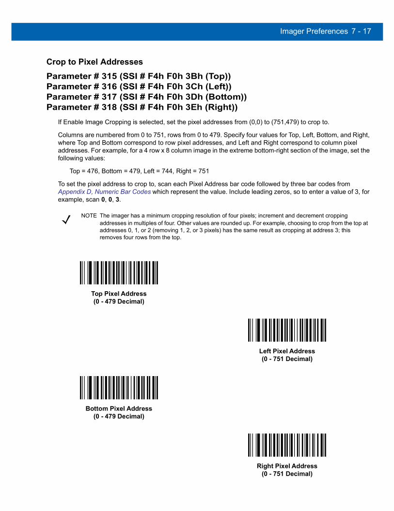
Imager Preferences 7 - 17
Crop to Pixel Addresses
Parameter # 315 (SSI # F4h F0h 3Bh (Top))Parameter # 316 (SSI # F4h F0h 3Ch (Left))Parameter # 317 (SSI # F4h F0h 3Dh (Bottom))Parameter # 318 (SSI # F4h F0h 3Eh (Right))
If Enable Image Cropping is selected, set the pixel addresses from (0,0) to (751,479) to crop to.
Columns are numbered from 0 to 751, rows from 0 to 479. Specify four values for Top, Left, Bottom, and Right, where Top and Bottom correspond to row pixel addresses, and Left and Right correspond to column pixel addresses. For example, for a 4 row x 8 column image in the extreme bottom-right section of the image, set the following values:
Top = 476, Bottom = 479, Left = 744, Right = 751
To set the pixel address to crop to, scan each Pixel Address bar code followed by three bar codes from Appendix D, Numeric Bar Codes which represent the value. Include leading zeros, so to enter a value of 3, for example, scan 0, 0, 3.
NOTE The imager has a minimum cropping resolution of four pixels; increment and decrement cropping addresses in multiples of four. Other values are rounded up. For example, choosing to crop from the top at addresses 0, 1, or 2 (removing 1, 2, or 3 pixels) has the same result as cropping at address 3; this removes four rows from the top.
Top Pixel Address(0 - 479 Decimal)
Left Pixel Address(0 - 751 Decimal)
Bottom Pixel Address(0 - 479 Decimal)
Right Pixel Address(0 - 751 Decimal)

7 - 18 DS457 Fixed Mount Imager Integration Guide
Image Resolution
Parameter # 302 (SSI # F0h 2Eh)This option alters image resolution before compression. Rows and columns are removed from the image, resulting in a smaller image containing the original content with reduced resolution.
Select one of the following values:
Resolution Value
Uncropped Image Size
Full 752 x 480
1/2 376 x 240
1/4 188 x 120
*Full Resolution(0)
1/2 Resolution(1)
1/4 Resolution (3)

Imager Preferences 7 - 19
Image Brightness (Target White)
Parameter # 390 (SSI # F0h 86h)This parameter sets the Target White value used in Snapshot and Video modes when using autoexposure. White and black are defined as 255 decimal and 0, respectively. Setting the value to the default of 180 results in a white level of ~180 for the image.
To set the Image Brightness parameter, scan Image Brightness below followed by three numeric bar codes representing the value. Include leading zeros. For example, to set an Image Brightness value of 99, scan 0, 9, 9. See Appendix D, Numeric Bar Codes for numeric bar codes.
*180
Image Brightness(3 digits)

7 - 20 DS457 Fixed Mount Imager Integration Guide
Image File Format Selector
Parameter # 304 (SSI # F0h 30h)Select an image format appropriate for the system (BMP, TIFF, or JPEG). The imager stores captured images in the selected format.
JPEG Image Options
Parameter # 299 (SSI # F0h 2Bh)JPEG images can be optimized for either size or for quality. Scan the Quality Selector bar code to enter a quality value; the imager then selects the corresponding image size. Scan the Size Selector bar code to enter a size value; the imager then selects the best image quality.
BMP File Format(3)
*JPEG File Format(1)
TIFF File Format(4)
*JPEG Quality Selector(1)
JPEG Size Selector(0)
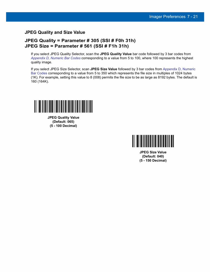
Imager Preferences 7 - 21
JPEG Quality and Size Value
JPEG Quality = Parameter # 305 (SSI # F0h 31h)JPEG Size = Parameter # 561 (SSI # F1h 31h)
If you select JPEG Quality Selector, scan the JPEG Quality Value bar code followed by 3 bar codes from Appendix D, Numeric Bar Codes corresponding to a value from 5 to 100, where 100 represents the highest quality image.
If you select JPEG Size Selector, scan JPEG Size Value followed by 3 bar codes from Appendix D, Numeric Bar Codes corresponding to a value from 5 to 350 which represents the file size in multiples of 1024 bytes (1K). For example, setting this value to 8 (008) permits the file size to be as large as 8192 bytes. The default is 160 (164K).
JPEG Quality Value (Default: 065)
(5 - 100 Decimal)
JPEG Size Value (Default: 040)
(5 - 150 Decimal)

7 - 22 DS457 Fixed Mount Imager Integration Guide
Image File Meta Data
Parameter # 693 (SSI # F1h B5h)Enable this option to tag images transmitted in JPEG format with the following EXIF 2.2 standard data fields:
• Time (since power up)
• Sensor used
• Device name
• Manufacturer
• Frame rate
• Host type
• Image number (since power up)
• Image Enhancement parameter setting
• Image Edge Sharpening parameter setting
• Image Contract Enhancement parameter setting.
This parameter has no effect on images transmitted in TIFF or BMP format.
Image Enhancement
Parameter # 564 (SSI # F1h 34h)This feature uses a combination of edge sharpening and contrast enhancement to produce an image that is visually pleasing. If you select User, also set the Image Edge Sharpening on page 7-23 and Image Contrast Enhancement on page 7-24 to enhance the image.
The levels of image enhancement are:
• Off (0) - Default
• Low (1)
• Med (2)
Enable Image File Meta Data(1)
*Disable Image File Meta Data(0)
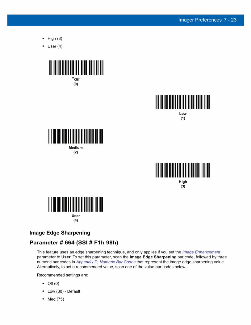
Imager Preferences 7 - 23
• High (3)
• User (4).
Image Edge Sharpening
Parameter # 664 (SSI # F1h 98h)This feature uses an edge sharpening technique, and only applies if you set the Image Enhancement parameter to User. To set this parameter, scan the Image Edge Sharpening bar code, followed by three numeric bar codes in Appendix D, Numeric Bar Codes that represent the image edge sharpening value. Alternatively, to set a recommended value, scan one of the value bar codes below.
Recommended settings are:
• Off (0)
• Low (30) - Default
• Med (75)
*Off(0)
Low(1)
Medium(2)
High (3)
User(4)

7 - 24 DS457 Fixed Mount Imager Integration Guide
• High (100).
Image Contrast Enhancement
Parameter # 666 (SSI # F1h 9Ah)Enable this feature to enhance the contrast of an image. This parameter only applies if you set the Image Enhancement parameter to User.
Image Edge Sharpening
Off(0)
*Low(30)
Medium(75)
High (100)
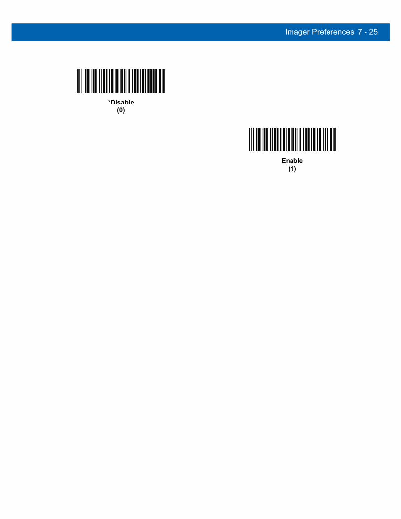
Imager Preferences 7 - 25
*Disable(0)
Enable(1)

7 - 26 DS457 Fixed Mount Imager Integration Guide
Image Rotation
Parameter # 665 (SSI # F1h 99h)This parameter controls the rotation of the image by 0, 90,180, or 270 degrees.
*Rotate 0o
(0)
Rotate 90o
(1)
Rotate 180o
(2)
Rotate 270o
(3)

Imager Preferences 7 - 27
Bits per Pixel
Parameter # 303 (SSI # F0h 2Fh)Select the number of significant bits per pixel (BPP) to use when capturing an image. Select 1 BPP for a black and white image, 4 BPP to assign 1 of 16 levels of grey to each pixel, or 8 BPP to assign 1 of 256 levels of grey to each pixel. The imager ignores these settings for JPEG files, which always use 8 BPP.
1 BPP(0)
4 BPP(1)
*8 BPP(2)

7 - 28 DS457 Fixed Mount Imager Integration Guide
Signature Capture
Parameter # 93 (SSI # 5Dh)A signature capture bar code is a special-purpose symbology which delineate a signature capture area in a document with a machine-readable format. The recognition pattern is variable so it can optionally provide an index to various signatures. The region inside the bar code pattern is considered the signature capture area.
Output File FormatDecoding a signature capture bar code de-skews the signature image and converts the image to a BMP, JPEG, or TIFF file format. The output data includes the file descriptor followed by the formatted signature image.
To enable or disable Signature Capture, scan the appropriate bar code below.
File Descriptor
Signature ImageOutput Format (1 byte)
Signature Type (1 byte)
Signature Image Size (4 bytes) (BIG
Endian)
JPEG - 1BMP - 3TIFF - 4
1-8 0x00000400 0x00010203…..
Enable Signature Capture(1)
*Disable Signature Capture(0)

Imager Preferences 7 - 29
Signature Capture File Format Selector
Parameter # 313 (SSI # F0h 39h)Select a signature file format appropriate for the system (BMP, TIFF, or JPEG). The imager stores captured signatures in the selected format.
BMP Signature Format(3)
*JPEG Signature Format(1)
TIFF Signature Format(4)

7 - 30 DS457 Fixed Mount Imager Integration Guide
Signature Capture Bits per Pixel
Parameter # 314 (SSI # F0h 3Ah)Select the number of significant bits per pixel (BPP) to use when capturing a signature. Select 1 BPP for a black and white image, 4 BPP to assign 1 of 16 levels of grey to each pixel, or 8 BPP to assign 1 of 256 levels of grey to each pixel. The imager ignores these settings for JPEG files, which always use 8 BPP.
Signature Capture Width
Parameter # 366 (SSI # F4h F0h 6Eh)The aspect ratio of the Signature Capture Width and Signature Capture Height parameters must match that of the signature capture area. For example, a 4 x 1 inch signature capture area requires a 4 to 1 aspect ratio of width to height.
To set the width of the signature capture box, scan the Signature Capture Width bar code, followed by 3 bar codes from Appendix D, Numeric Bar Codes corresponding to a value in the range of 040 to 752 decimal.
1 BPP(0)
4 BPP(1)
*8 BPP(2)
Signature Capture Width(Default: 400)
(040- 752 Decimal)

Imager Preferences 7 - 31
Signature Capture Height
Parameter # 367 (SSI # F4h F0h 6Fh)To set the height of the signature capture box, scan the Signature Capture Height bar code, followed by 3 bar codes from Appendix D, Numeric Bar Codes corresponding to a value in the range of 010 to 480 decimal.
Signature Capture JPEG Quality
Parameter # 421 (SSI # F0h A5h)Scan the JPEG Quality Value bar code followed by 3 bar codes from Appendix D, Numeric Bar Codes corresponding to a value from 005 to 100, where 100 represents the highest quality image.
Video Mode Format SelectorParameter # 916 (SSI # F2h 94h)
When the imager is in Video Mode, select whether to send data in BMP or JPEG format.
Signature Capture Height (Default: 100)(010 - 480 Decimal)
JPEG Quality Value (Default: 065)(5 - 100 Decimal)
BMP File Format(3)
*JPEG File Format(1)

7 - 32 DS457 Fixed Mount Imager Integration Guide
Video View Finder
Parameter # 324 (SSI # F0h 44h)Select Enable Video View Finder to project the video view finder while in Image Mode, or Disable Video View Finder to turn the video view finder off.
*Disable Video View Finder(0)
Enable Video View Finder(1)
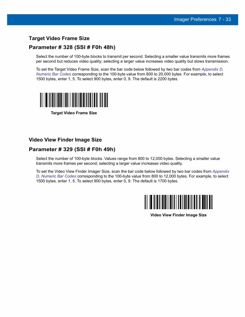
Imager Preferences 7 - 33
Target Video Frame Size
Parameter # 328 (SSI # F0h 48h)Select the number of 100-byte blocks to transmit per second. Selecting a smaller value transmits more frames per second but reduces video quality; selecting a larger value increases video quality but slows transmission.
To set the Target Video Frame Size, scan the bar code below followed by two bar codes from Appendix D, Numeric Bar Codes corresponding to the 100-byte value from 800 to 20,000 bytes. For example, to select 1500 bytes, enter 1, 5. To select 900 bytes, enter 0, 9. The default is 2200 bytes.
Video View Finder Image Size
Parameter # 329 (SSI # F0h 49h)Select the number of 100-byte blocks. Values range from 800 to 12,000 bytes. Selecting a smaller value transmits more frames per second; selecting a larger value increases video quality.
To set the Video View Finder Imager Size, scan the bar code below followed by two bar codes from Appendix D, Numeric Bar Codes corresponding to the 100-byte value from 800 to 12,000 bytes. For example, to select 1500 bytes, enter 1, 5. To select 900 bytes, enter 0, 9. The default is 1700 bytes.
Target Video Frame Size
Video View Finder Image Size

7 - 34 DS457 Fixed Mount Imager Integration Guide
Video Resolution
Parameter # 667 (SSI # F1h 9Bh)This parameter alters the video resolution before transmission. Rows and columns are removed from the image, resulting in a smaller video image containing the original content with reduced resolution.
Select one of the following values:
Resolution Value Video Image Size
Full 752 x 480
1/2 376 x 240
1/4 188 x 120
Full Resolution(0)
1/2 Resolution(1)
*1/4 Resolution(3)
CHAPTER 8SSI INTERFACE
IntroductionThis chapter describes the system requirements of the Simple Serial Interface (SSI), which provides a communications link between Zebra decoders (e.g., scan engines, imagers, hand-held scanners, two-dimensional scanners, hands-free scanners, and RF base stations) and a serial host. It provides the means for the host to control the imager.
CommunicationsAll communication between the imager and host occurs over the hardware interface lines using the SSI protocol. Refer to the Simple Serial Interface Programmer’s Guide, p/n 72-40451-xx, for more information on SSI.
The host and the imager exchange messages in packets. A packet is a collection of bytes framed by the proper SSI protocol formatting bytes. The maximum number of bytes per packet that the SSI protocol allows for any transaction is 257 (255 bytes + 2 byte checksum).
Decode data can be sent as ASCII data (unpacketed), or as part of a larger message (packeted), depending on the imager configuration.
SSI performs the following functions for the host device:
• Maintains a bi-directional interface with the imager
• Allows the host to send commands that control the imager
• Passes data from the imager to a host device in SSI packet format or straight decode message.
The working environment of the SSI consists of an imager, a serial cable which attaches to the host device, and in some instances, a power supply.
SSI transmits all decode data including special formatting (e.g., AIM ID). Parameter settings can control the format of the transmitted data.
The imager can also send parameter information, product identification information, or event codes to the host.
All commands sent between the imager and host must use the format described in the SSI Message Formats section. SSI Transactions on page 8-3 describes the required sequence of messages in specific cases.

8 - 2 DS457 Fixed Mount Imager Integration Guide
Table 8-1 lists all the SSI opcodes the imager supports. It identifies the SSI partner allowed to send a message of each type. The host transmits opcodes designated type H. The imager transmits type D opcodes, and either partner can transmit Host/Decoder (H/D) types.
For details of the SSI protocol, refer to the Simple Serial Interface Programmer's Guide (72-40451-xx).
Table 8-1 SSI Commands
Name Type Opcode Description
AIM_OFF H 0xC4 Deactivate aim pattern.
AIM_ON H 0xC5 Activate aim pattern.
BEEP H 0xE6 Sound the beeper.
CAPABILITIES_REPLY D 0xD4 Reply to CAPABILITIES_REQUEST; contains a list of the capabilities and commands the imager supports.
CAPABILITIES_REQUEST H 0xD3 Request capabilities report from the imager.
CMD_ACK H/D 0xD0 Positive acknowledgment of received packet.
CMD_NAK H/D 0xD1 Negative acknowledgment of received packet.
DECODE_DATA D 0xF3 Decode data in SSI packet format.
EVENT D 0xF6 Event indicated by associated event code.
LED_OFF H 0xE8 De-activate LED output.
LED_ON H 0xE7 Activate LED output.
PARAM_DEFAULTS H 0xC8 Set parameter default values.
PARAM_REQUEST H 0xC7 Request values of certain parameters.
PARAM_SEND H/D 0xC6 Send parameter values.
REPLY_ID D 0xA6 Reply to REQUEST_ID; contains imager's serial number.
REPLY_REVISION D 0xA4 Reply to REQUEST_REVISION contains imager's software/hardware configuration.
REQUEST_ID H 0xA3 Request the imager's serial number.
REQUEST_REVISION H 0xA3 Request the imager's configuration.
SCAN_DISABLE H 0xEA Prevent the operator from scanning bar codes.
SCAN_ENABLE H 0xE9 Permit bar code scanning.
SLEEP H 0xEB Request to place the imager into low power.
START_DECODE H 0xE4 Tell imager to attempt to decode a bar code.
STOP_DECODE H 0xE5 Tell imager to abort a decode attempt.
WAKEUP H N/A Wake up imager after it has entered low power mode.

SSI Interface 8 - 3
SSI Transactions
General Data Transactions
ACK/NAK HandshakingIf you enable ACK/NAK handshaking, all packeted messages must have a CMD_ACK or CMD_NAK response, unless the command description states otherwise. This parameter is enabled by default. Zebra recommends leaving this handshaking enabled to provide feedback to the host. Raw decode data and WAKEUP do not use ACK/NAK handshaking since they are not packeted data.
Following is an example of a problem which can occur if you disable ACK/NAK handshaking:
• The host sends a PARAM_SEND message to the imager to change the baud rate from 9600 to 19200.
• The imager cannot interpret the message.
• The imager does not implement the change the host requested.
• The host assumes that the parameter change occurred and acts accordingly.
• Communication is lost because the change did not occur on both sides.
If you enable ACK/NAK handshaking, the following occurs:
• The host sends a PARAM_SEND message.
• The imager cannot interpret the message.
• The imager CMD_NAKs the message.
• The host resends the message.
• The imager receives the message successfully, responds with CMD_ACK, and implements parameter changes.

8 - 4 DS457 Fixed Mount Imager Integration Guide
Transfer of Decode Data
The Decode Data Packet Format parameter controls how decode data is sent to the host. Set this parameter to send the data in a DECODE_DATA packet. Clear this parameter to transmit the data as raw ASCII data.
ACK/NAK Enabled and Packeted DataThe imager sends a DECODE_DATA message after a successful decode. The imager waits for a programmable time-out for a CMD_ACK response. If it does not receive the response, the imager tries to send two more times before issuing a host transmission error. If the imager receives a CMD_NAK from the host, it may attempt a retry depending on the cause field of the CMD_NAK message.
ACK/NAK Enabled and Unpacketed ASCII DataEven though the ACK/NAK handshaking is enabled, no handshaking occurs because the handshaking applies only to packeted data. In this example the packeted_decode parameter is disabled.
ACK/NAK Disabled and Packeted DECODE_DATAIn this example ACK/NAK does not occur even though packeted_decode is enabled because the ACK/NAK handshaking parameter is disabled.
NOTE When transmitting decode data as raw ASCII data, ACK/NAK handshaking does not apply regardless of the state of the ACK/NAK handshaking parameter.
Decoder
Data is captured by decoder
Host
(1)
DECODE_DATA
(2)
CMD_ACK
message sent
Decoder
Data is captured by decoder
HostASCII data
Decoder
Data is captured by decoder
Host(1)
DECODE_DATA
message sent

SSI Interface 8 - 5
ACK/NAK Disabled and Unpacketed ASCII DataData captured by the imager is sent to the host.
Communication Summary
RTS/CTS Lines All communication must use RTS/CTS handshaking as described in the Simple Serial Interface Programmer’s Guide, p/n 72-40451-xx. If hardware handshaking is disabled or bypassed, the WAKEUP command must be sent prior to all other communications, or the first byte of a communication message may be lost during the imager wakeup sequence.
ACK/NAK Option Enable or disable ACK/NAK handshaking. This handshaking is enabled by default and Zebra recommends leaving it enabled. Disabling this handshaking can cause communication problems, as handshaking is the only acknowledgment that a message was received, and if it was received correctly. ACK/NAK is not used with unpacketed decode data regardless of whether or not it is enabled.
Number of Data BitsAll communication with the imager must use 8-bit data.
Serial Response Time-outThe Serial Response Time-out parameter determines how long to wait for a handshaking response before trying again, or aborting any further attempts. Set the same value for both the host and imager.
RetriesWhen sending data, the host should resend twice after the initial send if the imager does not respond with an ACK or NAK (if ACK/NAK handshaking is enabled), or response data (e.g., PARAM_SEND, REPLY_REVISION). If the imager replies with a NAK RESEND, the host resends the data. All resent messages must have the resend bit set in the Status byte.
The imager resends data two times after the initial send if the host fails to reply with an ACK or NAK (if ACK/NAK handshaking is enabled).
Decoder
Data is captured by decoder
Host(1)
ASCII data sent
NOTE You can temporarily change the Serial Response Time-out when the host takes longer to process an ACK or longer data string. Zebra does not recommend frequent permanent changes due to limited write cycles of non-volatile memory.

8 - 6 DS457 Fixed Mount Imager Integration Guide
Baud Rate, Stop Bits, Parity, Response Time-out, ACK/NAK HandshakeIf you use PARAM_SEND to change these serial parameters, the ACK response to the PARAM_SEND uses the previous values for these parameters. The new values then take effect for the next transaction.
ErrorsThe imager issues a communication error when:
• The CTS line is asserted when the imager tries to transmit, and is still asserted on each of 2 successive retries
• Failure to receive an ACK or NAK after initial transmit and two resends.
Things to Remember When Using SSI CommunicationWhen not using hardware handshaking, space messages sufficiently apart. The host must not communicate with the imager if the imager is transmitting.
When using hardware handshaking, frame each message properly with the handshaking signals. Do not try to send two commands within the same handshaking frame.
There is a permanent/temporary bit in the PARAM_SEND message. Removing power from the imager discards temporary changes. Permanent changes are written to non-volatile memory. Frequent changes shorten the life of the non-volatile memory.

SSI Interface 8 - 7
Using Time Delay to Low Power Mode with SSITime Delay to Low Power Mode on page 6-17 provides bar codes to select a general time delay. To program a more specific delay value, use an SSI command according to Table 8-2.
Table 8-2 Values for Selecting Time Delay to Low Power
Value Timeout Value Timeout Value Timeout Value Timeout
0x00 15 Mins 0x10 1 Sec 0x20 1 Min 0x30 1 Hour
0x01 30 Mins 0x11 1 Sec 0x21 1 Min 0x31 1 Hour
0x02 60 Mins 0x12 2 Secs 0x22 2 Mins 0x32 2 Hours
0x03 90 Mins 0x13 3 Secs 0x23 3 Mins 0x33 3 Hours
N/A N/A 0x14 4 Secs 0x24 4 Mins 0x34 4 Hours
N/A N/A 0x15 5 Secs 0x25 5 Mins 0x35 5 Hours
N/A N/A 0x16 6 Secs 0x26 6 Mins 0x36 6 Hours
N/A N/A 0x17 7 Secs 0x27 7 Mins 0x37 7 Hours
N/A N/A 0x18 8 Secs 0x28 8 Mins 0x38 8 Hours
N/A N/A 0x19 9 Secs 0x29 9 Mins 0x39 9 Hours
N/A N/A 0x1A 10 Secs 0x2A 10 Mins 0x3A 10 Hours
N/A N/A 0x1B 15 Secs 0x2B 15 Mins 0x3B 15 Hours
N/A N/A 0x1C 20 Secs 0x2C 20 Mins 0x3C 20 Hours
N/A N/A 0x1D 30 Secs 0x2D 30 Mins 0x3D 30 Hours
N/A N/A 0x1E 45 Secs 0x2E 45 Mins 0x3E 45 Hours
N/A N/A 0x1F 60 Secs 0x2F 60 Mins 0x3F 60 Hours
CAUTION With hardware handshaking disabled, the DS457 wakes from low power mode upon receiving a character. However, the DS457 does not process this character or any others it receives during the 7 ms period following wakeup. Wait at least 7 ms after wakeup to send valid characters.

8 - 8 DS457 Fixed Mount Imager Integration Guide
Simple Serial Interface Default ParametersThis section describes how to set up the imager with an SSI host. When using SSI, program the imager via bar code menu or hosts commands.
Throughout the programming bar code menus, asterisks (*) indicate default values.
Table 8-3 lists the defaults for the SSI host. There are two ways to change the default values:
• Scan the appropriate bar codes in this guide. These new values replace the standard default values in memory. To recall the default parameter values, scan the *Restore Defaults bar code on page 6-5.
• Download data through the device’s serial port using SSI. Hexadecimal parameter numbers appear in this chapter below the parameter title, and options appear in parenthesis beneath the accompanying bar codes. Refer to the Simple Serial Interface (SSI) Programmer’s Guide for detailed instructions for changing parameters using this method.
*Baud Rate 9600(6)
Feature/Option* Indicates default
Option value for programming
NOTE Most computer monitors allow scanning the bar codes directly on the screen. When scanning from the screen, be sure to set the document magnification to a level where you can see the bar code clearly, and bars and/or spaces are not merging.
NOTE See Appendix A, Standard Default Parameters for all user preferences, hosts, symbologies, and miscellaneous default parameters.
Table 8-3 SSI Default Table
Parameter Parameter Number SSI Number Default Page
Number
Select SSI Host N/A N/A N/A 8-9
Baud Rate 156 9Ch 9600 8-10
Parity 258 9Eh None 8-11
Check Parity 151 97h Disable 8-12
Software Handshaking 159 9Fh ACK/NAK 8-12
Host RTS Line State 154 9Ah Low 8-13
Decode Data Packet Format 238 EEh Send Raw Decode Data 8-13
Host Serial Response Time-out 155 9Bh 2 sec 8-14
Host Character Time-out 239 EFh 200 msec 8-15
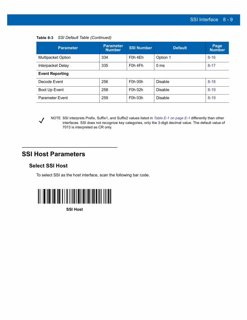
SSI Interface 8 - 9
SSI Host Parameters
Select SSI HostTo select SSI as the host interface, scan the following bar code.
Multipacket Option 334 F0h 4Eh Option 1 8-16
Interpacket Delay 335 F0h 4Fh 0 ms 8-17
Event Reporting
Decode Event 256 F0h 00h Disable 8-18
Boot Up Event 258 F0h 02h Disable 8-19
Parameter Event 259 F0h 03h Disable 8-19
Table 8-3 SSI Default Table (Continued)
Parameter Parameter Number SSI Number Default Page
Number
NOTE SSI interprets Prefix, Suffix1, and Suffix2 values listed in Table E-1 on page E-1 differently than other interfaces. SSI does not recognize key categories, only the 3-digit decimal value. The default value of 7013 is interpreted as CR only.
SSI Host

8 - 10 DS457 Fixed Mount Imager Integration Guide
Baud Rate
Parameter # 156 (SSI # 9Ch)
Baud rate is the number of bits of data transmitted per second. Set the imager's baud rate to match the baud rate setting of the host device. Otherwise, data may not reach the host device or may reach it in distorted form.
*Baud Rate 9600(6)
Baud Rate 19,200(7)
Baud Rate 38,400(8)
Baud Rate 57,600(10)
Baud Rate 115,200(11)
Baud Rate 230,400(13)

SSI Interface 8 - 11
Baud Rate (continued)
Parity
Parameter # 258 (SSI # 9Eh)
A parity check bit is the most significant bit of each ASCII coded character. Select the parity type according to host device requirements.
• Select Odd parity and the parity bit has a value 0 or 1, based on data, to ensure that an odd number of 1 bits is contained in the coded character.
• Select Even parity and the parity bit has a value 0 or 1, based on data, to ensure that an even number of 1 bits is contained in the coded character.
• If no parity is required, select None.
Baud Rate 460,800(14)
Baud Rate 921,600(15)
Odd(0)
Even(1)
*None(4)

8 - 12 DS457 Fixed Mount Imager Integration Guide
Check Parity
Parameter # 151 (SSI # 97h)
Select whether or not to check the parity of received characters. Use the Parity parameter to select the type of parity.
Software Handshaking
Parameter # 159 (SSI # 9Fh)
This parameter offers control of data transmission in addition to the control hardware handshaking offers. Hardware handshaking is always enabled; you cannot disable it.
• Disable ACK/NAK Handshaking: When this option is selected, the imager neither generates nor expects ACK/NAK handshaking packets.
• Enable ACK/NAK Handshaking: When this option is selected, after transmitting data, the imager expects either an ACK or NAK response from the host. The imager also ACKs or NAKs messages from the host.
The imager waits up to the programmable Host Serial Response Time-out to receive an ACK or NAK. If the imager does not get a response in this time, it resends its data up to two times before discarding the data and declaring a transmit error.
*Do Not Check Parity(0)
Check Parity(1)
Disable ACK/NAK(0)
*Enable ACK/NAK(1)

SSI Interface 8 - 13
Host RTS Line State
Parameter # 154 (SSI # 9Ah)
This parameter sets the expected idle state of the Serial Host RTS line.
The SSI Interface is used with host applications which also implement the SSI protocol. However, you can use the imager in a "scan-and-transmit" mode to communicate with any standard serial communication software on a host PC (see Decode Data Packet Format on page 8-13). If transmission errors occur in this mode, the host PC may be asserting hardware handshaking lines which interfere with the SSI protocol. Scan the Host: RTS High bar code to address this problem.
Decode Data Packet Format
Parameter # 238 (SSI # EEh)
This parameter selects whether to transmit decoded data in raw format (unpacketed), or with the packet format defined by the serial protocol.
Selecting the raw format disables ACK/NAK handshaking for decode data.
*Host: RTS Low(0)
Host: RTS High(1)
*Send Raw Decode Data(0)
Send Packeted Decode Data(1)
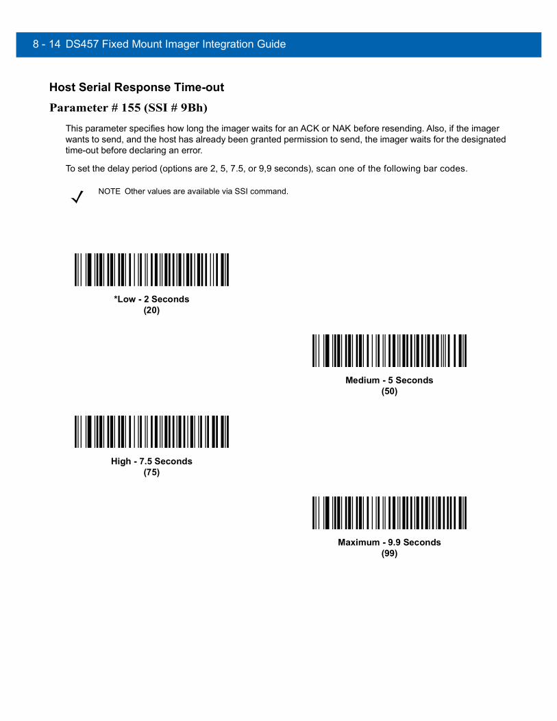
8 - 14 DS457 Fixed Mount Imager Integration Guide
Host Serial Response Time-out
Parameter # 155 (SSI # 9Bh)
This parameter specifies how long the imager waits for an ACK or NAK before resending. Also, if the imager wants to send, and the host has already been granted permission to send, the imager waits for the designated time-out before declaring an error.
To set the delay period (options are 2, 5, 7.5, or 9,9 seconds), scan one of the following bar codes.
NOTE Other values are available via SSI command.
*Low - 2 Seconds(20)
Medium - 5 Seconds(50)
High - 7.5 Seconds(75)
Maximum - 9.9 Seconds(99)

SSI Interface 8 - 15
Host Character Time-out
Parameter # 239 (SSI # EFh)
This parameter determines the maximum time the imager waits between characters transmitted by the host before discarding the received data and declaring an error.
To set the delay period (options are 200, 500, 750, or 990 ms), scan one of the following bar codes.
NOTE Other values are available via SSI command.
*Low - 200 ms(20)
Medium - 500 ms(50)
High - 750 ms(75)
Maximum - 990 ms(99)

8 - 16 DS457 Fixed Mount Imager Integration Guide
Multipacket Option
Parameter # 334 (SSI # F0h, 4Eh)
This parameter controls ACK/NAK handshaking for multi-packet transmissions.
• Multi-Packet Option 1: The host sends an ACK / NAK for each data packet during a multi-packet transmission.
• Multi-Packet Option 2: The imager sends data packets continuously, with no ACK/NAK handshaking to pace the transmission. The host, if overrun, can use hardware handshaking to temporarily delay imager transmissions. At the end of transmission, the imager waits for a CMD_ACK or CMD_NAK.
• Multi-Packet Option 3: Option 3 is the same as option 2 with the addition of a programmable interpacket delay.
*Multipacket Option 1(0)
Multipacket Option 2(1)
Multipacket Option 3(2)

SSI Interface 8 - 17
Interpacket Delay
Parameter # 335 (SSI # F0h, 4Fh)
This parameter specifies the interpacket delay if you selected Multipacket Option 3.
To set the delay period (options are 0, 25, 50, 75, or 99 ms), scan one of the following bar codes.
NOTE Other values are available via SSI command.
*Minimum - 0 ms(0)
Low - 25 ms(25)
Medium - 50 ms(50)
High - 75 ms(75)
Maximum - 99 ms(99)

8 - 18 DS457 Fixed Mount Imager Integration Guide
Event ReportingThe host can request the imager to provide certain information (events) relative to the imager’s behavior. Enable or disable the events listed in Table 8-4 and on the following pages by scanning the appropriate bar codes.
Decode Event
Parameter # 256 (SSI # F0h, 00h)
When enabled, the imager generates a message to the host upon a successful bar code decode. When disabled, no notification is sent.
Table 8-4 Event Codes
Event Class Event Code Reported
Decode Event Non parameter decode 0x01
Boot Up Event System power-up 0x03
Parameter Event Parameter entry errorParameter storedDefaults set (and parameter event is enabled by default)Number expected
0x070x080x0A
0x0F
Enable Decode Event(1)
*Disable Decode Event(0)

SSI Interface 8 - 19
Boot Up Event
Parameter # 258 (SSI # F0h, 02h)
When enabled, the imager generates a message to the host whenever power is applied. When disabled, no notification is sent.
Parameter Event
Parameter # 259 (SSI # F0h, 03h)
When enabled, the imager generates a message to the host when one of the events specified in Table 8-4 on page 8-18 occurs. When disabled, no notification is sent.
Enable Boot Up Event(1)
*Disable Boot Up Event(0)
Enable Parameter Event(1)
*Disable Parameter Event(0)

8 - 20 DS457 Fixed Mount Imager Integration Guide

CHAPTER 9SERIAL INTERFACE
IntroductionThis chapter describes how to set up the imager with a serial host. The serial interface connects the imager to point-of-sale devices, host computers, or other devices with an available serial port (e.g., com port).
If the host is not listed in Table 9-2, refer to the documentation for the host device to set communication parameters to match the host.
Throughout the programming bar code menus, asterisks (*) indicate default values.
NOTE The imager uses TTL signal levels, which interface with most system architectures. System architectures that use RS-232C signal levels require conversion circuitry.
*Baud Rate 57,600 Feature/Option* Indicates Default
NOTE The SSI Host on page 8-9 is automatically selected when a serial cable is attached. To select another RS-232 host, select one of the Serial Host Types on page 9-5, and then scan other bar code menus in this chapter as part of initial configuration.
Most computer monitors allow scanning the bar codes directly on the screen. When scanning from the screen, be sure to set the document magnification to a level where you can see the bar code clearly, and bars and/or spaces are not merging.
CAUTION The DS457 wakes from low power mode upon receiving a character. However, the DS457 does not process this character or any others it receives during the 7 ms period following wakeup. Wait at least 7 ms after wakeup to send valid characters.

9 - 2 DS457 Fixed Mount Imager Integration Guide
Serial Parameter DefaultsTable 9-1 lists the defaults for serial host parameters. To change any option, scan the appropriate bar code(s) provided in the Serial Host Parameters section beginning on page 9-3.
NOTE See Appendix A, Standard Default Parameters for all user preferences, hosts, symbologies, and miscellaneous default parameters.
Table 9-1 Serial Host Default Table
Parameter Default Page Number
Serial Host Parameters
Serial Host Types Standard RS-232 9-5
Baud Rate 9600 9-7
Parity Type None 9-9
Data Bits 8-Bit 9-9
Check Receive Errors Enable 9-10
Hardware Handshaking None 9-11
Software Handshaking None 9-13
Host Serial Response Time-out 2 Sec 9-15
RTS Line State Low RTS 9-16
Beep on <BEL> Disable 9-16
Intercharacter Delay 0 msec 9-17
Nixdorf Beep/LED Options Normal Operation 9-18
Ignore Unknown Characters Send Bar Code 9-18
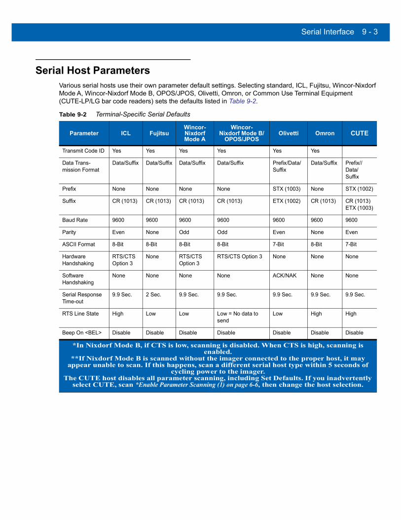
Serial Interface 9 - 3
Serial Host ParametersVarious serial hosts use their own parameter default settings. Selecting standard, ICL, Fujitsu, Wincor-Nixdorf Mode A, Wincor-Nixdorf Mode B, OPOS/JPOS, Olivetti, Omron, or Common Use Terminal Equipment (CUTE-LP/LG bar code readers) sets the defaults listed in Table 9-2.
Table 9-2 Terminal-Specific Serial Defaults
Parameter ICL FujitsuWincor-NixdorfMode A
Wincor-Nixdorf Mode B/
OPOS/JPOSOlivetti Omron CUTE
Transmit Code ID Yes Yes Yes Yes Yes Yes
Data Trans-mission Format
Data/Suffix Data/Suffix Data/Suffix Data/Suffix Prefix/Data/Suffix
Data/Suffix Prefix//Data/Suffix
Prefix None None None None STX (1003) None STX (1002)
Suffix CR (1013) CR (1013) CR (1013) CR (1013) ETX (1002) CR (1013) CR (1013) ETX (1003)
Baud Rate 9600 9600 9600 9600 9600 9600 9600
Parity Even None Odd Odd Even None Even
ASCII Format 8-Bit 8-Bit 8-Bit 8-Bit 7-Bit 8-Bit 7-Bit
Hardware Handshaking
RTS/CTS Option 3
None RTS/CTSOption 3
RTS/CTS Option 3 None None None
Software Handshaking
None None None None ACK/NAK None None
Serial Response Time-out
9.9 Sec. 2 Sec. 9.9 Sec. 9.9 Sec. 9.9 Sec. 9.9 Sec. 9.9 Sec.
RTS Line State High Low Low Low = No data to send
Low High High
Beep On <BEL> Disable Disable Disable Disable Disable Disable Disable
*In Nixdorf Mode B, if CTS is low, scanning is disabled. When CTS is high, scanning is enabled.
**If Nixdorf Mode B is scanned without the imager connected to the proper host, it may appear unable to scan. If this happens, scan a different serial host type within 5 seconds of
cycling power to the imager.The CUTE host disables all parameter scanning, including Set Defaults. If you inadvertently
select CUTE, scan *Enable Parameter Scanning (1) on page 6-6, then change the host selection.
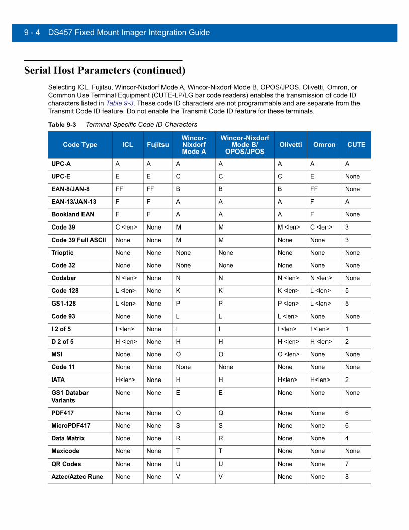
9 - 4 DS457 Fixed Mount Imager Integration Guide
Serial Host Parameters (continued)Selecting ICL, Fujitsu, Wincor-Nixdorf Mode A, Wincor-Nixdorf Mode B, OPOS/JPOS, Olivetti, Omron, or Common Use Terminal Equipment (CUTE-LP/LG bar code readers) enables the transmission of code ID characters listed in Table 9-3. These code ID characters are not programmable and are separate from the Transmit Code ID feature. Do not enable the Transmit Code ID feature for these terminals.
Table 9-3 Terminal Specific Code ID Characters
Code Type ICL FujitsuWincor-NixdorfMode A
Wincor-Nixdorf Mode B/
OPOS/JPOSOlivetti Omron CUTE
UPC-A A A A A A A A
UPC-E E E C C C E None
EAN-8/JAN-8 FF FF B B B FF None
EAN-13/JAN-13 F F A A A F A
Bookland EAN F F A A A F None
Code 39 C <len> None M M M <len> C <len> 3
Code 39 Full ASCII None None M M None None 3
Trioptic None None None None None None None
Code 32 None None None None None None None
Codabar N <len> None N N N <len> N <len> None
Code 128 L <len> None K K K <len> L <len> 5
GS1-128 L <len> None P P P <len> L <len> 5
Code 93 None None L L L <len> None None
I 2 of 5 I <len> None I I I <len> I <len> 1
D 2 of 5 H <len> None H H H <len> H <len> 2
MSI None None O O O <len> None None
Code 11 None None None None None None None
IATA H<len> None H H H<len> H<len> 2
GS1 Databar Variants
None None E E None None None
PDF417 None None Q Q None None 6
MicroPDF417 None None S S None None 6
Data Matrix None None R R None None 4
Maxicode None None T T None None None
QR Codes None None U U None None 7
Aztec/Aztec Rune None None V V None None 8

Serial Interface 9 - 5
Serial Host Types
To select a serial host interface, scan one of the following bar codes.
NOTE Scanning Standard RS-232 activates the serial driver, but does not change port settings (e.g., parity, data bits, handshaking). Selecting another serial host type bar code changes these settings.
NOTE Selecting one of the Serial Host Types disables SSI support. To restore SSI support, scan SSI Host on page 8-9.
NOTE The CUTE host disables all parameter scanning, including Set Defaults. If you inadvertently select CUTE, scan *Enable Parameter Scanning (1) on page 6-6, then change the host selection.
*Standard RS-232
ICL Serial
Wincor-Nixdorf Serial Mode A
Wincor-Nixdorf Serial Mode B

9 - 6 DS457 Fixed Mount Imager Integration Guide
Serial Host Types (continued)
Olivetti ORS4500
Omron
OPOS/JPOS
Fujitsu Serial
CUTE

Serial Interface 9 - 7
Baud Rate
Baud rate is the number of bits of data transmitted per second. Set the imager's baud rate to match the baud rate setting of the host device. Otherwise, data may not reach the host device or may reach it in distorted form.
*Baud Rate 9600
Baud Rate 19,200
Baud Rate 38,400
Baud Rate 57,600
Baud Rate 115,200
Baud Rate 230,400

9 - 8 DS457 Fixed Mount Imager Integration Guide
Baud Rate (continued)
Baud Rate 460,800
Baud Rate 921,600

Serial Interface 9 - 9
Parity
A parity check bit is the most significant bit of each ASCII coded character. Select the parity type according to host device requirements.
• Select Odd parity to set the parity bit value to 0 or 1, based on data, to ensure that an odd number of 1 bits are contained in the coded character.
• Select Even parity to set the parity bit value to 0 or 1, based on data, to ensure that an even number of 1 bits are contained in the coded character.
• Select None when no parity bit is required.
Data BitsThis parameter allows the imager to interface with devices requiring a 7-bit or 8-bit ASCII protocol.
Odd
Even
*None
7-Bit
*8-Bit

9 - 10 DS457 Fixed Mount Imager Integration Guide
Check Receive ErrorsSelect whether or not to check the parity, framing, and overrun of received characters. The parity value of received characters is verified against the setting of Parity on page 9-9.
*Check For Received Errors
Do Not Check For Received Errors

Serial Interface 9 - 11
Hardware Handshaking
The data interface consists of a serial port designed to operate either with or without the hardware handshaking lines Request to Send (RTS) and Clear to Send (CTS).
If Standard RTS/CTS handshaking is not selected, scan data transmits as it becomes available. Select Standard RTS/CTS handshaking to transmit scan data according to the following sequence:
• The imager reads the CTS line for activity. If CTS is asserted, the imager waits up to the Host Serial Response Time-out for the host to de-assert the CTS line. If, after the Host Serial Response Time-out (default) the CTS line is still asserted, the imager sounds a transmit error and discards any scanned data.
• When the CTS line is de-asserted, the imager asserts the RTS line and waits up to the Host Serial Response Time-out for the host to assert CTS. When the host asserts CTS, data transmits. If, after the Host Serial Response Time-out (default) the CTS line is not asserted, the imager sounds a transmit error and discards the data.
• When data transmission completes, the imager de-asserts RTS 10 msec after sending the last character.
• The host responds by negating CTS. The imager checks for a de-asserted CTS upon the next transmission of data.
During data transmission, the CTS line should be asserted. If CTS is deasserted for more than 50 ms between characters, the imager aborts transmission, sounds a transmission error, and discards the data.
If the above communication sequence fails, the imager issues an error indication. In this case, the data is lost and must be rescanned.
If hardware handshaking and software handshaking are both enabled, hardware handshaking takes precedence.
• None: Scan this bar code to disable hardware handshaking.
• Standard RTS/CTS: Scan this bar code to select Standard RTS/CTS Hardware Handshaking.
• RTS/CTS Option 1: The imager asserts RTS before transmitting and ignores the state of CTS. The imager de-asserts RTS when transmission completes.
• RTS/CTS Option 2: RTS is always high or low (user-programmed logic level). However, the imager waits for CTS to be asserted before transmitting data. If CTS is not asserted within Host Serial Response Time-out (default), the imager issues an error indication and discards the data.
• RTS/CTS Option 3: The imager asserts RTS prior to any data transmission, regardless of the state of CTS. The imager waits up to Host Serial Response Time-out (default) for CTS to be asserted. If CTS is not asserted during this time, the imager issues an error indication and discards the data. The imager de-asserts RTS when transmission completes.
NOTE The DTR signal is jumpered to the active state.

9 - 12 DS457 Fixed Mount Imager Integration Guide
Hardware Handshaking (continued)
*None
Standard RTS/CTS
RTS/CTS Option 1
RTS/CTS Option 2
RTS/CTS Option 3

Serial Interface 9 - 13
Software Handshaking
This parameter offers control of data transmission in addition to, or instead of, the control hardware handshaking offers. There are five options.
If software handshaking and hardware handshaking are both enabled, Hardware Handshaking takes precedence.
• None: Data transmits immediately. No response is expected from host.
• ACK/NAK: After transmitting data, the imager expects either an ACK or NAK response from the host. When the imager receives a NAK, it transmits the same data again and waits for either an ACK or NAK. After three unsuccessful attempts to send data when NAKs are received, the imager issues an error indication and discards the data.
The imager waits up to the programmable Host Serial Response Time-out to receive an ACK or NAK. If the imager does not receive a response in this time, it issues an error indication and discards the data. There are no retries when a time-out occurs.
• ENQ: The imager waits for an ENQ character from the host before transmitting data. If the imager does not receive an ENQ within the Host Serial Response Time-out, it issues an error indication and discards the data. The host must transmit an ENQ character at least every Host Serial Response Time-out to prevent transmission errors.
• ACK/NAK with ENQ: This combines the two previous options. For re-transmissions of data due to a NAK from the host, an additional ENQ is not required.
• XON/XOFF: An XOFF character turns the imager transmission off until the imager receives an XON character. There are two situations for XON/XOFF:• The imager receives an XOFF before it has data to send. When the imager has data to send, it waits
up to the Host Serial Response Time-out for an XON character before transmission. If it does not receive an XON within this time, the imager issues an error indication and discards the data.
• The imager receives an XOFF during a transmission. Data transmission then stops after sending the current byte. When the imager receives an XON character, it sends the rest of the data message. The imager waits indefinitely for the XON.

9 - 14 DS457 Fixed Mount Imager Integration Guide
Software Handshaking (continued)
*None
ACK/NAK
ENQ
ACK/NAK with ENQ
XON/XOFF

Serial Interface 9 - 15
Host Serial Response Time-out
This parameter specifies how long the imager waits for an ACK, NAK, or CTS before determining that a transmission error occurred. This only applies when in one of the ACK/NAK software handshaking modes, or RTS/CTS hardware handshaking mode.
*Minimum: 2 Sec
Low: 2.5 Sec
Medium: 5 Sec
High: 7.5 Sec
Maximum: 9.9 Sec

9 - 16 DS457 Fixed Mount Imager Integration Guide
RTS Line StateThis parameter sets the idle state of the Serial Host RTS line. Scan a bar code below to select Low RTS or High RTS line state.
Beep on <BEL>When this parameter is enabled, the imager issues a beep when it detects a <BEL> character on the serial line. <BEL> gains a user's attention to an illegal entry or other important event.
*Host: Low RTS
Host: High RTS
Beep On <BEL> Character(Enable)
*Do Not Beep On <BEL> Character(Disable)
NOTE A NULL character must be sent to the imager before BEL to ensure the BEL character is processed correctly.

Serial Interface 9 - 17
Intercharacter Delay
This parameter specifies the intercharacter delay inserted between character transmissions.
*Minimum: 0 msec
Low: 25 msec
Medium: 50 msec
High: 75 msec
Maximum: 99 msec

9 - 18 DS457 Fixed Mount Imager Integration Guide
Nixdorf Beep/LED Options
Select Nixdorf Mode B to indicate when the imager beeps and turns on its LED after a decode.
Ignore Unknown CharactersUnknown characters are characters the host does not recognize. Select Send Bar Codes with Unknown Characters to send all bar code data except for unknown characters. The imager issues no error beeps. Select Do Not Send Bar Codes With Unknown Characters to send bar code data up to the first unknown character. The imager issues an error beep.
*Normal Operation(Beep/LED immediately after decode)
Beep/LED After Transmission
Beep/LED After CTS Pulse
*Send Bar Code(with unknown characters)
Do Not Send Bar Codes(with unknown characters)

Serial Interface 9 - 19
ASCII Character Set for Serial HostsYou can assign the values in Table 9-4 as prefixes or suffixes for ASCII character data transmission.
Table 9-4 Prefix/Suffix Values
Prefix/Suffix Value
Full ASCIICode 39 Encode Character ASCII Character
1000 %U NUL
1001 $A SOH
1002 $B STX
1003 $C ETX
1004 $D EOT
1005 $E ENQ
1006 $F ACK
1007 $G BELL
1008 $H BCKSPC
1009 $I HORIZ TAB
1010 $J LF/NW LN
1011 $K VT
1012 $L FF
1013 $M CR/ENTER
1014 $N SO
1015 $O SI
1016 $P DLE
1017 $Q DC1/XON
1018 $R DC2
1019 $S DC3/XOFF
1020 $T DC4
1021 $U NAK
1022 $V SYN
1023 $W ETB
1024 $X CAN
1025 $Y EM
1026 $Z SUB
1027 %A ESC

9 - 20 DS457 Fixed Mount Imager Integration Guide
1028 %B FS
1029 %C GS
1030 %D RS
1031 %E US
1032 Space Space
1033 /A !
1034 /B "
1035 /C #
1036 /D $
1037 /E %
1038 /F &
1039 /G ‘
1040 /H (
1041 /I )
1042 /J *
1043 /K +
1044 /L ,
1045 - -
1046 . .
1047 /O /
1048 0 0
1049 1 1
1050 2 2
1051 3 3
1052 4 4
1053 5 5
1054 6 6
1055 7 7
1056 8 8
1057 9 9
1058 /Z :
Table 9-4 Prefix/Suffix Values (Continued)
Prefix/Suffix Value
Full ASCIICode 39 Encode Character ASCII Character

Serial Interface 9 - 21
1059 %F ;
1060 %G <
1061 %H =
1062 %I >
1063 %J ?
1064 %V @
1065 A A
1066 B B
1067 C C
1068 D D
1069 E E
1070 F F
1071 G G
1072 H H
1073 I I
1074 J J
1075 K K
1076 L L
1077 M M
1078 N N
1079 O O
1080 P P
1081 Q Q
1082 R R
1083 S S
1084 T T
1085 U U
1086 V V
1087 W W
1088 X X
1089 Y Y
Table 9-4 Prefix/Suffix Values (Continued)
Prefix/Suffix Value
Full ASCIICode 39 Encode Character ASCII Character

9 - 22 DS457 Fixed Mount Imager Integration Guide
1090 Z Z
1091 %K [
1092 %L \
1093 %M ]
1094 %N ^
1095 %O _
1096 %W `
1097 +A a
1098 +B b
1099 +C c
1100 +D d
1101 +E e
1102 +F f
1103 +G g
1104 +H h
1105 +I i
1106 +J j
1107 +K k
1108 +L l
1109 +M m
1110 +N n
1111 +O o
1112 +P p
1113 +Q q
1114 +R r
1115 +S s
1116 +T t
1117 +U u
1118 +V v
1119 +W w
1120 +X x
Table 9-4 Prefix/Suffix Values (Continued)
Prefix/Suffix Value
Full ASCIICode 39 Encode Character ASCII Character

Serial Interface 9 - 23
1121 +Y y
1122 +Z z
1123 %P {
1124 %Q |
1125 %R }
1126 %S ~
1127 Undefined
7013 ENTER
Table 9-4 Prefix/Suffix Values (Continued)
Prefix/Suffix Value
Full ASCIICode 39 Encode Character ASCII Character

9 - 24 DS457 Fixed Mount Imager Integration Guide

CHAPTER 10USB INTERFACE
IntroductionThis chapter describes how to set up the imager with a USB host. The imager connects directly to a USB host, or a powered USB hub, which powers it. No additional power supply is required.
Throughout the programming bar code menus, asterisks (*) indicate default values.
*North American Standard USB Keyboard Feature/Option* Indicates Default
NOTE Most computer monitors allow scanning the bar codes directly on the screen. When scanning from the screen, be sure to set the document magnification to a level where you can see the bar code clearly, and bars and/or spaces are not merging.

10 - 2 DS457 Fixed Mount Imager Integration Guide
USB Parameter DefaultsTable 10-1 lists the defaults for USB host parameters. To change any option, scan the appropriate bar code(s) provided in the Parameter Descriptions section beginning on page 10-3.
NOTE See Appendix A, Standard Default Parameters for all user preferences, hosts, symbologies, and miscellaneous default parameters.
Table 10-1 USB Host Default Table
Parameter Default Page Number
USB Host Parameters
USB Device Type USB HID Keyboard 10-3
Symbol Native API (SNAPI) Status Handshaking Enable 10-5
USB Country Keyboard Types (Country Codes) North American 10-6
USB Keystroke Delay No Delay 10-8
USB CAPS Lock Override Disable 10-8
USB Ignore Unknown Characters Enable 10-9
Emulate Keypad Disable 10-9
Emulate Keypad with Leading Zero Disable 10-10
Quick Keypad Emulation Disable 10-10
USB FN1 Substitution Disable 10-11
Function Key Mapping Disable 10-11
Simulated Caps Lock Disable 10-12
Convert Case None 10-13
USB Static CDC Enable 10-13
USB Ignore Beep Directive Honor 10-14
USB Ignore Type Directive Honor 10-14
USB Polling Interval 3 msec 10-15
Fast HID Keyboard Enable 10-17
IBM Specification Level Version 0 (Original) 10-17
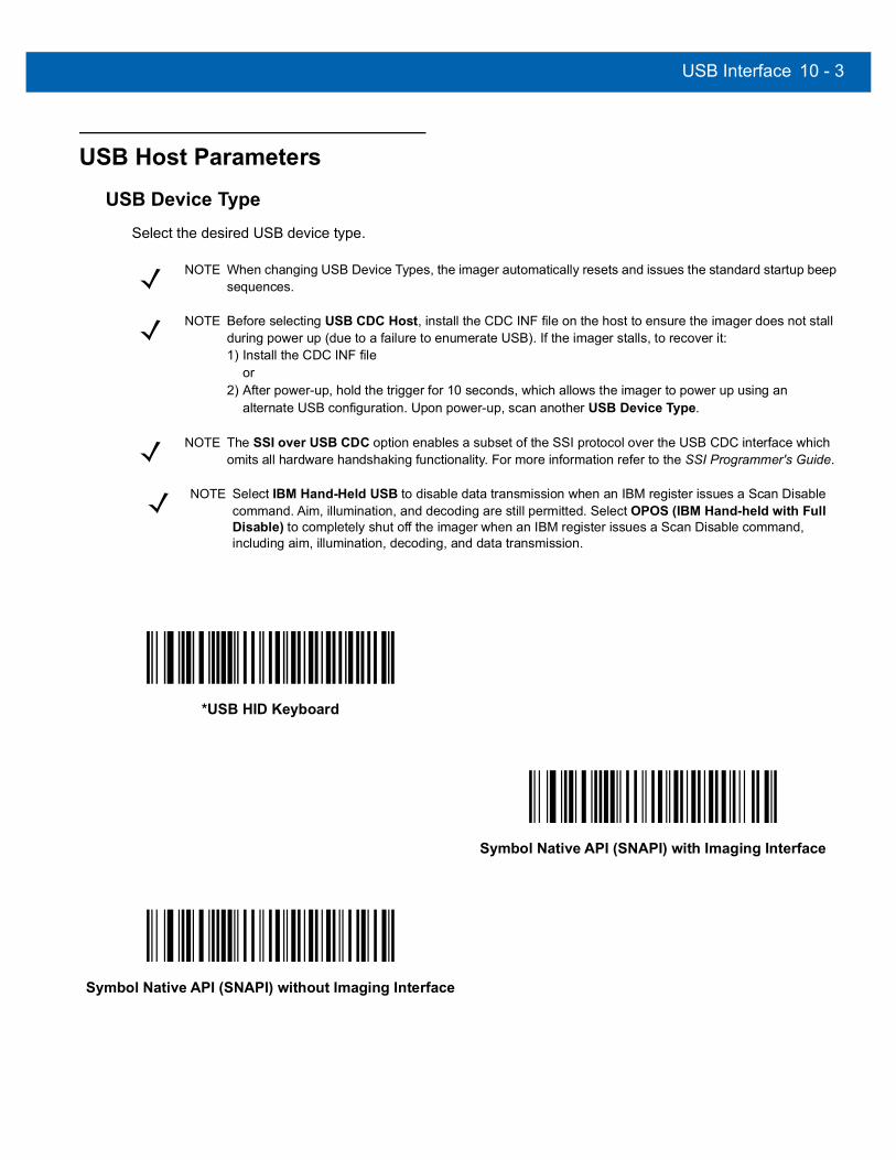
USB Interface 10 - 3
USB Host Parameters
USB Device TypeSelect the desired USB device type.
NOTE When changing USB Device Types, the imager automatically resets and issues the standard startup beep sequences.
NOTE Before selecting USB CDC Host, install the CDC INF file on the host to ensure the imager does not stall during power up (due to a failure to enumerate USB). If the imager stalls, to recover it:1) Install the CDC INF file
or 2) After power-up, hold the trigger for 10 seconds, which allows the imager to power up using an
alternate USB configuration. Upon power-up, scan another USB Device Type.
NOTE The SSI over USB CDC option enables a subset of the SSI protocol over the USB CDC interface which omits all hardware handshaking functionality. For more information refer to the SSI Programmer's Guide.
NOTE Select IBM Hand-Held USB to disable data transmission when an IBM register issues a Scan Disable command. Aim, illumination, and decoding are still permitted. Select OPOS (IBM Hand-held with Full Disable) to completely shut off the imager when an IBM register issues a Scan Disable command, including aim, illumination, decoding, and data transmission.
*USB HID Keyboard
Symbol Native API (SNAPI) with Imaging Interface
Symbol Native API (SNAPI) without Imaging Interface

10 - 4 DS457 Fixed Mount Imager Integration Guide
USB Device Type (continued)
USB CDC Host
Simple COM Port Emulation
SSI over USB CDC
IBM Hand-Held USB
OPOS (IBM Hand-held with Full Disable)
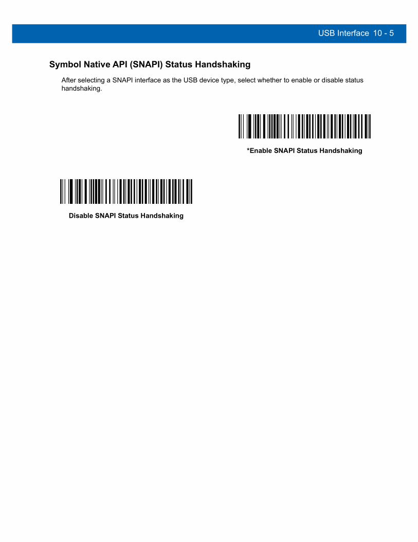
USB Interface 10 - 5
Symbol Native API (SNAPI) Status HandshakingAfter selecting a SNAPI interface as the USB device type, select whether to enable or disable status handshaking.
*Enable SNAPI Status Handshaking
Disable SNAPI Status Handshaking

10 - 6 DS457 Fixed Mount Imager Integration Guide
USB Country Keyboard Types (Country Codes)
Scan the bar code corresponding to the keyboard type. This setting applies only to the USB Keyboard HID device.
NOTE When changing USB country keyboard types the imager automatically resets. The imager issues the standard startup beep sequences.
*North American Standard USB Keyboard
German Windows
French Windows
French Canadian Windows 95/98
French Canadian Windows 2000/XP
French Belgian Windows

USB Interface 10 - 7
USB Country Keyboard Types (continued)
Spanish Windows
Italian Windows
Swedish Windows
UK English Windows
Japanese Windows (ASCII)
Portuguese-Brazilian Windows

10 - 8 DS457 Fixed Mount Imager Integration Guide
USB Keystroke Delay
This parameter sets the delay, in milliseconds, between emulated keystrokes. Scan a bar code below to increase the delay when hosts require a slower data transmission.
USB CAPS Lock OverrideThis option applies only to the USB Keyboard HID device. Enable this to preserve the case of the data regardless of the state of the caps lock key. This setting is always enabled for the Japanese, Windows (ASCII) keyboard type and can not be disabled.
*No Delay
Medium Delay (20 msec)
Long Delay (40 msec)
Override Caps Lock Key(Enable)
*Do Not Override Caps Lock Key(Disable)

USB Interface 10 - 9
USB Ignore Unknown Characters
This option applies only to the USB Keyboard HID device and IBM device. Unknown characters are characters the host does not recognize. Select Send Bar Codes With Unknown Characters to send all bar code data except for unknown characters. No error beeps sound. When Do Not Send Bar Codes With Unknown Characters is selected, for IBM devices, bar codes containing at least one unknown character are not sent to the host, and an error beep sounds. For USB Keyboard HID devices, the bar code characters up to the unknown character are sent, and an error beep sounds.
Emulate KeypadEnable this to send all characters as ASCII sequences over the numeric keypad. For example ASCII A is sent as “ALT make” 0 6 5 “ALT Break”. This allows support for other country variants.
*Send Bar Codes with Unknown Characters(Transmit)
Do Not Send Bar Codes with Unknown Characters(Disable)
*Disable Keypad Emulation
Enable Keypad Emulation
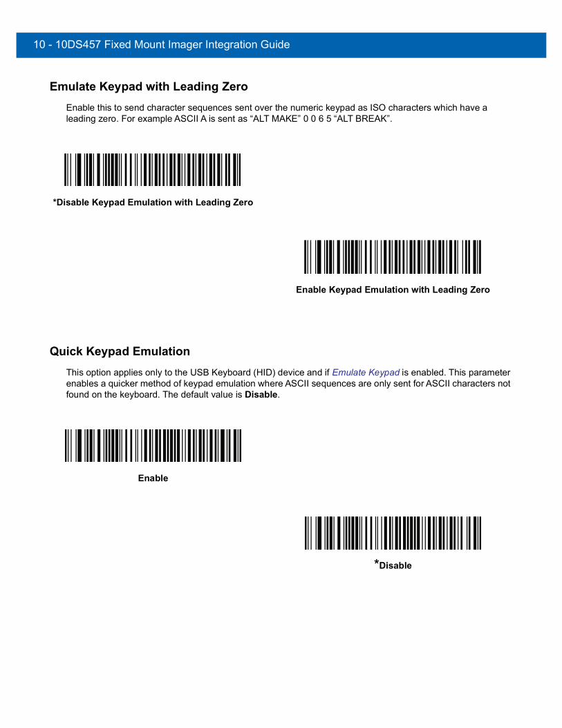
10 - 10DS457 Fixed Mount Imager Integration Guide
Emulate Keypad with Leading ZeroEnable this to send character sequences sent over the numeric keypad as ISO characters which have a leading zero. For example ASCII A is sent as “ALT MAKE” 0 0 6 5 “ALT BREAK”.
Quick Keypad EmulationThis option applies only to the USB Keyboard (HID) device and if Emulate Keypad is enabled. This parameter enables a quicker method of keypad emulation where ASCII sequences are only sent for ASCII characters not found on the keyboard. The default value is Disable.
*Disable Keypad Emulation with Leading Zero
Enable Keypad Emulation with Leading Zero
Enable
*Disable

USB Interface10 - 11
USB Keyboard FN1 SubstitutionThis option applies only to the USB Keyboard HID device. Enable this to replace any FN1 characters in an EAN 128 bar code with a Key Category and value (see FN1 Substitution Values on page 6-40 to set the Key Category and Key Value).
Function Key MappingASCII values under 32 are normally sent as control-key sequences (see Table 10-2 on page 10-18). Enable this to send the keys in bold in place of the standard key mapping. Table entries that do not have a bold entry remain the same whether or not this parameter is enabled.
Enable FN1 Substitution
*Disable FN1 Substitution
*Disable Function Key Mapping
Enable Function Key Mapping

10 - 12DS457 Fixed Mount Imager Integration Guide
Simulated Caps Lock
Enable this to invert upper and lower case characters on the bar code as if the Caps Lock state is enabled on the keyboard. This inversion occurs regardless of the keyboard’s current Caps Lock state.
*Disable Simulated Caps Lock
Enable Simulated Caps Lock
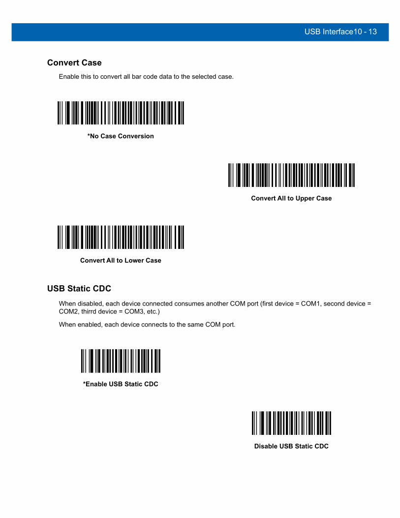
USB Interface10 - 13
Convert Case
Enable this to convert all bar code data to the selected case.
USB Static CDCWhen disabled, each device connected consumes another COM port (first device = COM1, second device = COM2, thirrd device = COM3, etc.)
When enabled, each device connects to the same COM port.
*No Case Conversion
Convert All to Upper Case
Convert All to Lower Case
*Enable USB Static CDC
Disable USB Static CDC

10 - 14DS457 Fixed Mount Imager Integration Guide
USB Ignore Beep DirectiveThis applies only to IBM hand-held, IBM table-top, and OPOS devices. Scan one of the following bar codes to honor or ignore a beep directive. All directives are still acknowledged as if they were processed.
USB Ignore Type DirectiveThis applies only to IBM hand-held, IBM table-top, and OPOS devices. Scan one of the following bar codes to honor or ignore a code type enable/disable directive. All directives are still acknowledged as if they were processed.
*Honor USB Beep Directive
Ignore USB Beep Directive
*Honor USB Ignore Type Directive
Ignore USB Ignore Type Directive
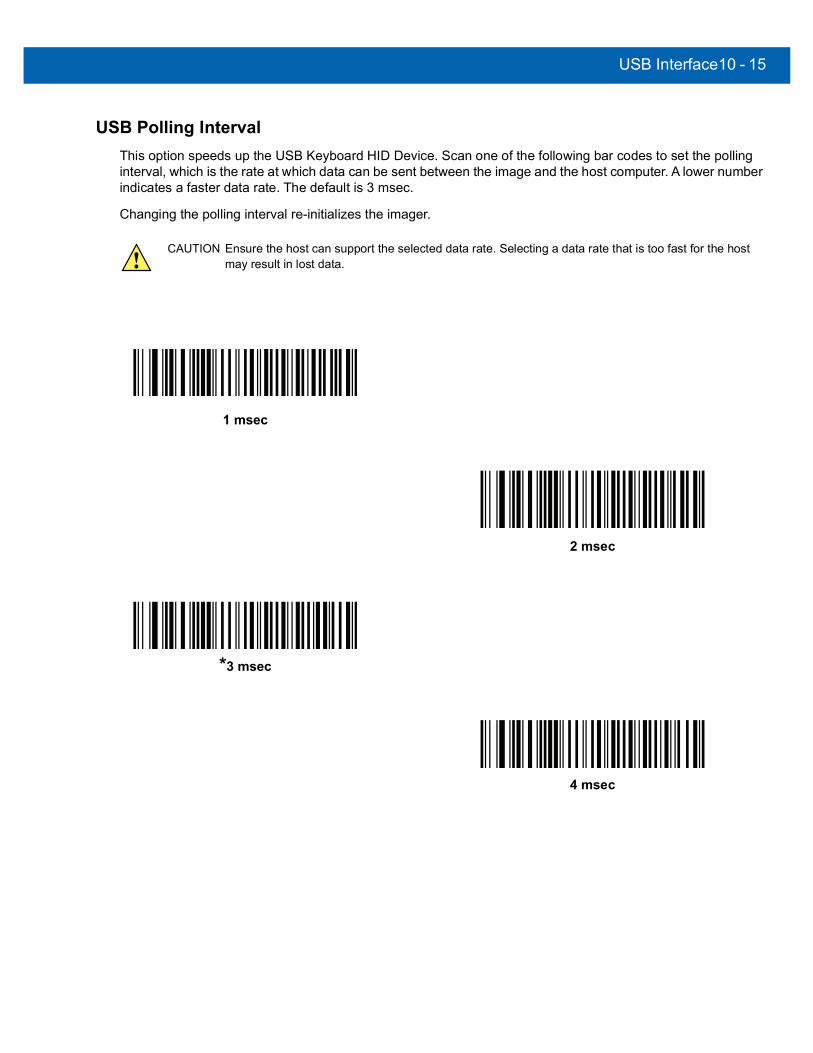
USB Interface10 - 15
USB Polling Interval
This option speeds up the USB Keyboard HID Device. Scan one of the following bar codes to set the polling interval, which is the rate at which data can be sent between the image and the host computer. A lower number indicates a faster data rate. The default is 3 msec.
Changing the polling interval re-initializes the imager.
CAUTION Ensure the host can support the selected data rate. Selecting a data rate that is too fast for the host may result in lost data.
1 msec
2 msec
*3 msec
4 msec

10 - 16DS457 Fixed Mount Imager Integration Guide
USB Polling Interval (continued)
5 msec
6 msec
7 msec
8 msec
9 msec
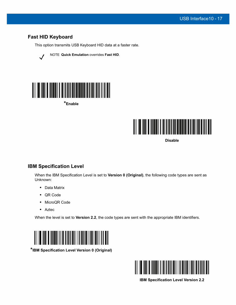
USB Interface10 - 17
Fast HID Keyboard
This option transmits USB Keyboard HID data at a faster rate.
IBM Specification LevelWhen the IBM Specification Level is set to Version 0 (Original), the following code types are sent as Unknown:
• Data Matrix
• QR Code
• MicroQR Code
• Aztec
When the level is set to Version 2.2, the code types are sent with the appropriate IBM identifiers.
NOTE Quick Emulation overrides Fast HID.
*Enable
Disable
*IBM Specification Level Version 0 (Original)
IBM Specification Level Version 2.2
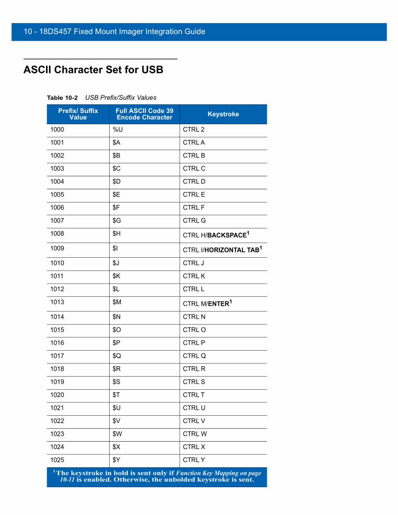
10 - 18DS457 Fixed Mount Imager Integration Guide
ASCII Character Set for USB
Table 10-2 USB Prefix/Suffix Values
Prefix/ Suffix Value
Full ASCII Code 39 Encode Character Keystroke
1000 %U CTRL 2
1001 $A CTRL A
1002 $B CTRL B
1003 $C CTRL C
1004 $D CTRL D
1005 $E CTRL E
1006 $F CTRL F
1007 $G CTRL G
1008 $H CTRL H/BACKSPACE1
1009 $I CTRL I/HORIZONTAL TAB1
1010 $J CTRL J
1011 $K CTRL K
1012 $L CTRL L
1013 $M CTRL M/ENTER1
1014 $N CTRL N
1015 $O CTRL O
1016 $P CTRL P
1017 $Q CTRL Q
1018 $R CTRL R
1019 $S CTRL S
1020 $T CTRL T
1021 $U CTRL U
1022 $V CTRL V
1023 $W CTRL W
1024 $X CTRL X
1025 $Y CTRL Y1The keystroke in bold is sent only if Function Key Mapping on page
10-11 is enabled. Otherwise, the unbolded keystroke is sent.

USB Interface10 - 19
1026 $Z CTRL Z
1027 %A CTRL [/ESC1
1028 %B CTRL \
1029 %C CTRL ]
1030 %D CTRL 6
1031 %E CTRL -
1032 Space Space
1033 /A !
1034 /B “
1035 /C #
1036 /D $
1037 /E %
1038 /F &
1039 /G ‘
1040 /H (
1041 /I )
1042 /J *
1043 /K +
1044 /L ,
1045 - -
1046 . .
1047 /O /
1048 0 0
1049 1 1
1050 2 2
1051 3 3
1052 4 4
1053 5 5
1054 6 6
Table 10-2 USB Prefix/Suffix Values (Continued)
Prefix/ Suffix Value
Full ASCII Code 39 Encode Character Keystroke
1The keystroke in bold is sent only if Function Key Mapping on page 10-11 is enabled. Otherwise, the unbolded keystroke is sent.

10 - 20DS457 Fixed Mount Imager Integration Guide
1055 7 7
1056 8 8
1057 9 9
1058 /Z :
1059 %F ;
1060 %G <
1061 %H =
1062 %I >
1063 %J ?
1064 %V @
1065 A A
1066 B B
1067 C C
1068 D D
1069 E E
1070 F F
1071 G G
1072 H H
1073 I I
1074 J J
1075 K K
1076 L L
1077 M M
1078 N N
1079 O O
1080 P P
1081 Q Q
1082 R R
1083 S S
Table 10-2 USB Prefix/Suffix Values (Continued)
Prefix/ Suffix Value
Full ASCII Code 39 Encode Character Keystroke
1The keystroke in bold is sent only if Function Key Mapping on page 10-11 is enabled. Otherwise, the unbolded keystroke is sent.

USB Interface10 - 21
1084 T T
1085 U U
1086 V V
1087 W W
1088 X X
1089 Y Y
1090 Z Z
1091 %K [
1092 %L \
1093 %M ]
1094 %N ^
1095 %O _
1096 %W `
1097 +A a
1098 +B b
1099 +C c
1100 +D d
1101 +E e
1102 +F f
1103 +G g
1104 +H h
1105 +I i
1106 +J j
1107 +K k
1108 +L l
1109 +M m
1110 +N n
1111 +O o
1112 +P p
Table 10-2 USB Prefix/Suffix Values (Continued)
Prefix/ Suffix Value
Full ASCII Code 39 Encode Character Keystroke
1The keystroke in bold is sent only if Function Key Mapping on page 10-11 is enabled. Otherwise, the unbolded keystroke is sent.

10 - 22DS457 Fixed Mount Imager Integration Guide
1113 +Q q
1114 +R r
1115 +S s
1116 +T t
1117 +U u
1118 +V v
1119 +W w
1120 +X x
1121 +Y y
1122 +Z z
1123 %P {
1124 %Q |
1125 %R }
1126 %S ~
Table 10-3 USB ALT Key Character Set
ALT Keys Keystroke
2064 ALT 2
2065 ALT A
2066 ALT B
2067 ALT C
2068 ALT D
2069 ALT E
2070 ALT F
2071 ALT G
2072 ALT H
2073 ALT I
2074 ALT J
2075 ALT K
2076 ALT L
Table 10-2 USB Prefix/Suffix Values (Continued)
Prefix/ Suffix Value
Full ASCII Code 39 Encode Character Keystroke
1The keystroke in bold is sent only if Function Key Mapping on page 10-11 is enabled. Otherwise, the unbolded keystroke is sent.
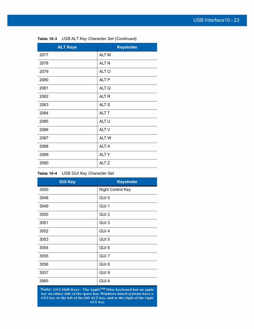
USB Interface10 - 23
2077 ALT M
2078 ALT N
2079 ALT O
2080 ALT P
2081 ALT Q
2082 ALT R
2083 ALT S
2084 ALT T
2085 ALT U
2086 ALT V
2087 ALT W
2088 ALT X
2089 ALT Y
2090 ALT Z
Table 10-4 USB GUI Key Character Set
GUI Key Keystroke
3000 Right Control Key
3048 GUI 0
3049 GUI 1
3050 GUI 2
3051 GUI 3
3052 GUI 4
3053 GUI 5
3054 GUI 6
3055 GUI 7
3056 GUI 8
3057 GUI 9
3065 GUI A
Note: GUI Shift Keys - The Apple™ iMac keyboard has an apple key on either side of the space bar. Windows-based systems have a GUI key to the left of the left ALT key, and to the right of the right
ALT key.
Table 10-3 USB ALT Key Character Set (Continued)
ALT Keys Keystroke

10 - 24DS457 Fixed Mount Imager Integration Guide
3066 GUI B
3067 GUI C
3068 GUI D
3069 GUI E
3070 GUI F
3071 GUI G
3072 GUI H
3073 GUI I
3074 GUI J
3075 GUI K
3076 GUI L
3077 GUI M
3078 GUI N
3079 GUI O
3080 GUI P
3081 GUI Q
3082 GUI R
3083 GUI S
3084 GUI T
3085 GUI U
3086 GUI V
3087 GUI W
3088 GUI X
3089 GUI Y
3090 GUI Z
Table 10-4 USB GUI Key Character Set (Continued)
GUI Key Keystroke
Note: GUI Shift Keys - The Apple™ iMac keyboard has an apple key on either side of the space bar. Windows-based systems have a GUI key to the left of the left ALT key, and to the right of the right
ALT key.
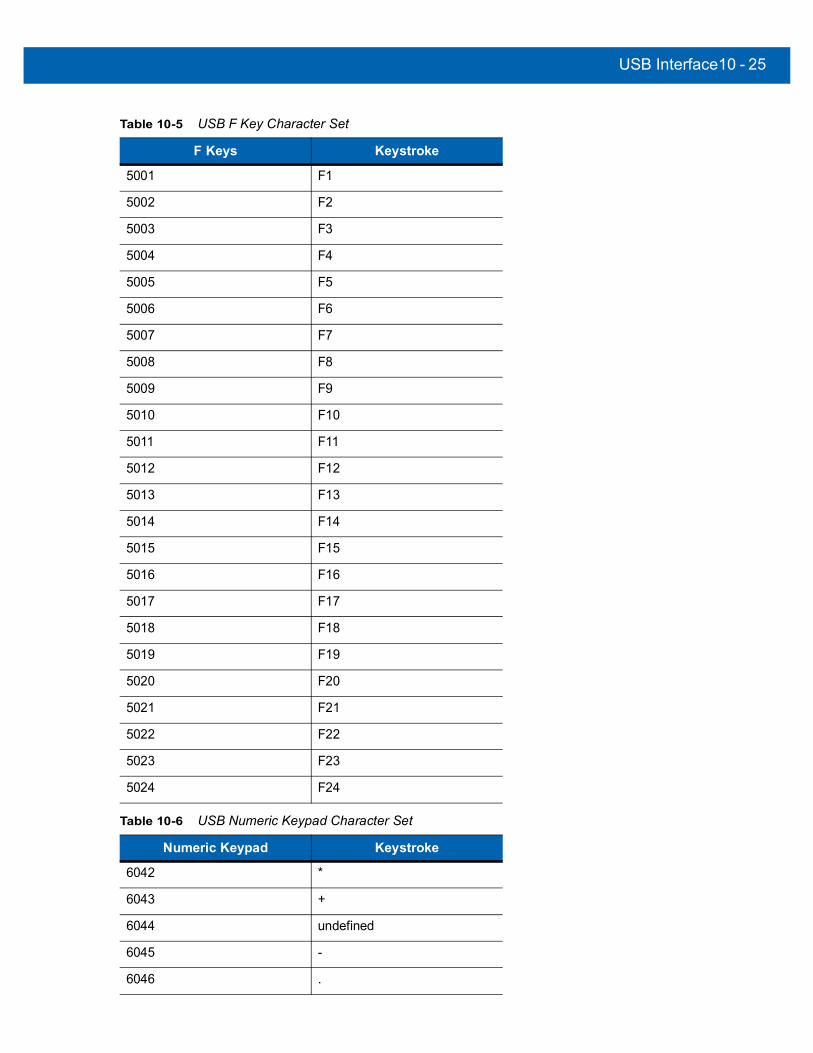
USB Interface10 - 25
Table 10-5 USB F Key Character Set
F Keys Keystroke
5001 F1
5002 F2
5003 F3
5004 F4
5005 F5
5006 F6
5007 F7
5008 F8
5009 F9
5010 F10
5011 F11
5012 F12
5013 F13
5014 F14
5015 F15
5016 F16
5017 F17
5018 F18
5019 F19
5020 F20
5021 F21
5022 F22
5023 F23
5024 F24
Table 10-6 USB Numeric Keypad Character Set
Numeric Keypad Keystroke
6042 *
6043 +
6044 undefined
6045 -
6046 .

10 - 26DS457 Fixed Mount Imager Integration Guide
6047 /
6048 0
6049 1
6050 2
6051 3
6052 4
6053 5
6054 6
6055 7
6056 8
6057 9
6058 Enter
6059 Num Lock
Table 10-7 USB Extended Keypad Character Set
Extended Keypad Keystroke
7001 Break
7002 Delete
7003 PgUp
7004 End
7005 Pg Dn
7006 Pause
7007 Scroll Lock
7008 Backspace
7009 Tab
7010 Print Screen
7011 Insert
7012 Home
7013 Enter
7014 Escape
7015 Up Arrow
Table 10-6 USB Numeric Keypad Character Set (Continued)
Numeric Keypad Keystroke

USB Interface10 - 27
7016 Down Arrow
7017 Left Arrow
7018 Right Arrow
Table 10-7 USB Extended Keypad Character Set (Continued)
Extended Keypad Keystroke

10 - 28DS457 Fixed Mount Imager Integration Guide

CHAPTER 11OCR READING
IntroductionThis chapter describes how to set up the imager for OCR reading. The DS457 can read 6 to 60 point OCR typeface. It supports font types OCR-A, OCR-B, MICR-E13B, and US Currency Serial Number.
OCR is not as secure as a bar code. To decrease OCR misdecodes and speed OCR reading, set an accurate OCR template and character subset, and use a check digit.
All OCR fonts are disabled by default. Enabling OCR can slow bar code decoding. Enabling more than one OCR font could also slow OCR decoding and impact OCR decoding accuracy.
Throughout the programming bar code menus, asterisks (*) indicate default values.
*Disable OCR-A Feature/Option* Indicates Default
NOTE Most computer monitors allow scanning the bar codes directly on the screen. When scanning from the screen, be sure to set the document magnification to a level where you can see the bar code clearly, and bars and/or spaces are not merging.

11 - 2 DS457 Fixed Mount Imager Integration Guide
OCR Parameter DefaultsTable 11-1 lists the defaults for OCR parameters. To change any option, scan the appropriate bar code(s) provided in the Parameter Descriptions section beginning on page 11-3.
NOTE See Appendix A, Standard Default Parameters for all user preferences, hosts, symbologies, and miscellaneous default parameters.
Table 11-1 OCR Default Table
Parameter Parameter Number SSI Number Default Page Number
OCR Parameters
OCR-A 680 F1h A8h Disable 11-3
OCR-A Variant 684 F1h ACh Full ASCII 11-3
OCR-B 681 F1h A9h Disable 11-5
OCR-B Variant 685 F1h ADh Full ASCII 11-6
MICR E13B 682 F1h AAh Disable 11-9
US Currency 683 F1h ABh Disable 11-10
OCR Orientation 687 F1h AFh 0o 11-10
OCR Lines 691 F1h B3h 1 11-12
OCR Minimum Characters 689 F1h B1h 3 11-13
OCR Maximum Characters 690 F1h B2h 100 11-13
OCR Security Level 554 F1h 2Ah 80 11-13
OCR Subset 686 F1h AEh Selected font variant
11-14
OCR Quiet Zone 695 F1h B7h 50 11-14
OCR Bright Illumination 701 F1h BDh Disable 11-15
OCR Template 547 F1h 23h 54R 11-16
OCR Check Digit Modulus 688 F1h B0h 1 11-25
OCR Check Digit Multiplier 700 F1h BCh 121212121212 11-26
OCR Check Digit Validation 694 F1h B6h None 11-27
Inverse OCR 856 F2h 58h None 11-31
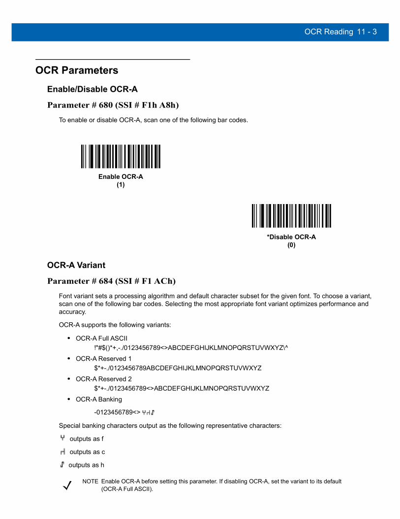
OCR Reading 11 - 3
OCR Parameters
Enable/Disable OCR-A
Parameter # 680 (SSI # F1h A8h)
To enable or disable OCR-A, scan one of the following bar codes.
OCR-A Variant
Parameter # 684 (SSI # F1 ACh)
Font variant sets a processing algorithm and default character subset for the given font. To choose a variant, scan one of the following bar codes. Selecting the most appropriate font variant optimizes performance and accuracy.
OCR-A supports the following variants:
• OCR-A Full ASCII!"#$()*+,-./0123456789<>ABCDEFGHIJKLMNOPQRSTUVWXYZ\^
• OCR-A Reserved 1$*+-./0123456789ABCDEFGHIJKLMNOPQRSTUVWXYZ
• OCR-A Reserved 2$*+-./0123456789<>ABCDEFGHIJKLMNOPQRSTUVWXYZ
• OCR-A Banking
-0123456789<>
Special banking characters output as the following representative characters:
outputs as f
outputs as c
outputs as h
Enable OCR-A(1)
*Disable OCR-A(0)
NOTE Enable OCR-A before setting this parameter. If disabling OCR-A, set the variant to its default (OCR-A Full ASCII).
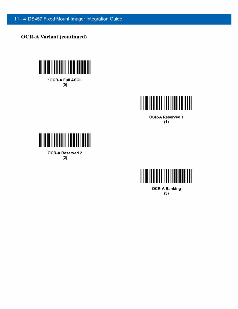
11 - 4 DS457 Fixed Mount Imager Integration Guide
OCR-A Variant (continued)
*OCR-A Full ASCII(0)
OCR-A Reserved 1(1)
OCR-A Reserved 2(2)
OCR-A Banking(3)

OCR Reading 11 - 5
Enable/Disable OCR-B
Parameter # 681 (SSI # F1h A9h)
To enable or disable OCR-B, scan one of the following bar codes.
Enable OCR-B(1)
*Disable OCR-B(0)

11 - 6 DS457 Fixed Mount Imager Integration Guide
OCR-B Variant
Parameter # 685 (SSI # F1 ADh)
OCR-B has the following variants. Selecting the most appropriate font variant affects performance and accuracy.
• OCR-B Full ASCII!#$%()*+,-./0123456789<>ABCDEFGHIJKLMNOPQRSTUVWXYZ^|Ñ
• OCR-B Banking#+-0123456789<>JNP|
• OCR-B Limited+,-./0123456789<>ACENPSTVX
• OCR-B ISBN 10-Digit Book Numbers-0123456789>BCEINPSXz
• OCR-B ISBN 10 or 13-Digit Book Numbers-0123456789>BCEINPSXz
• OCR-B Travel Document Version 1 (TD1) 3-Line ID Cards-0123456789<ABCDEFGHIJKLMNOPQRSTUVWXYZ
• OCR-B Travel Document Version 2 (TD2) 2-Line ID Cards-0123456789<ABCDEFGHIJKLMNOPQRSTUVWXYZ
• OCR-B Travel Document 2 or 3-Line ID Cards Auto-Detect!#$%()*+,-./0123456789<>ABCDEFGHIJKLMNOPQRSTUVWXYZ^|Ñ
• OCR-B Passport-0123456789<ABCDEFGHIJKLMNOPQRSTUVWXYZÑ
• OCR-B Visa Type A-0123456789<ABCDEFGHIJKLMNOPQRSTUVWXYZ
• OCR-B Visa Type B-0123456789<ABCDEFGHIJKLMNOPQRSTUVWXYZÑ
To choose a variant, scan one of the following bar codes. Selecting the following OCR-B variants automatically sets the appropriate OCR Lines on page 11-12. These five variants invoke extensive special algorithms and checking for that particular document type:
Variant OCR Lines SettingPassport 2TD1 ID Cards 3TD2 ID Cards 2Visa Type A 2Visa Type B 2
Selecting one of the ISBN Book Numbers automatically applies the appropriate ISBN checksum, so you do not need to set this.

OCR Reading 11 - 7
OCR-B Variant (continued)
For the best performance in passport reading, fix the target passport and the imager in place (6.5 - 7.5”).
NOTE Enable OCR-B before setting this parameter. If disabling OCR-B, set the variant to its default (OCR-B Full ASCII).
*OCR-B Full ASCII(0)
OCR-B Banking(1)
OCR-B Limited(2)
OCR-B ISBN 10-Digit Book Numbers(6)
OCR-B ISBN 10 or 13-Digit Book Numbers(7)
OCR-B Travel Document Version 1 (TD1)3 Line ID Cards
(3)

11 - 8 DS457 Fixed Mount Imager Integration Guide
OCR-B Variant (continued)
OCR-B Travel Document Version 2 (TD2)2-Line ID Cards
(8)
Travel Document 2 or 3-Line ID Cards Auto-Detect(14)
OCR-B Passport(4)
OCR-B Visa Type A(9)
OCR-B Visa Type B(10)
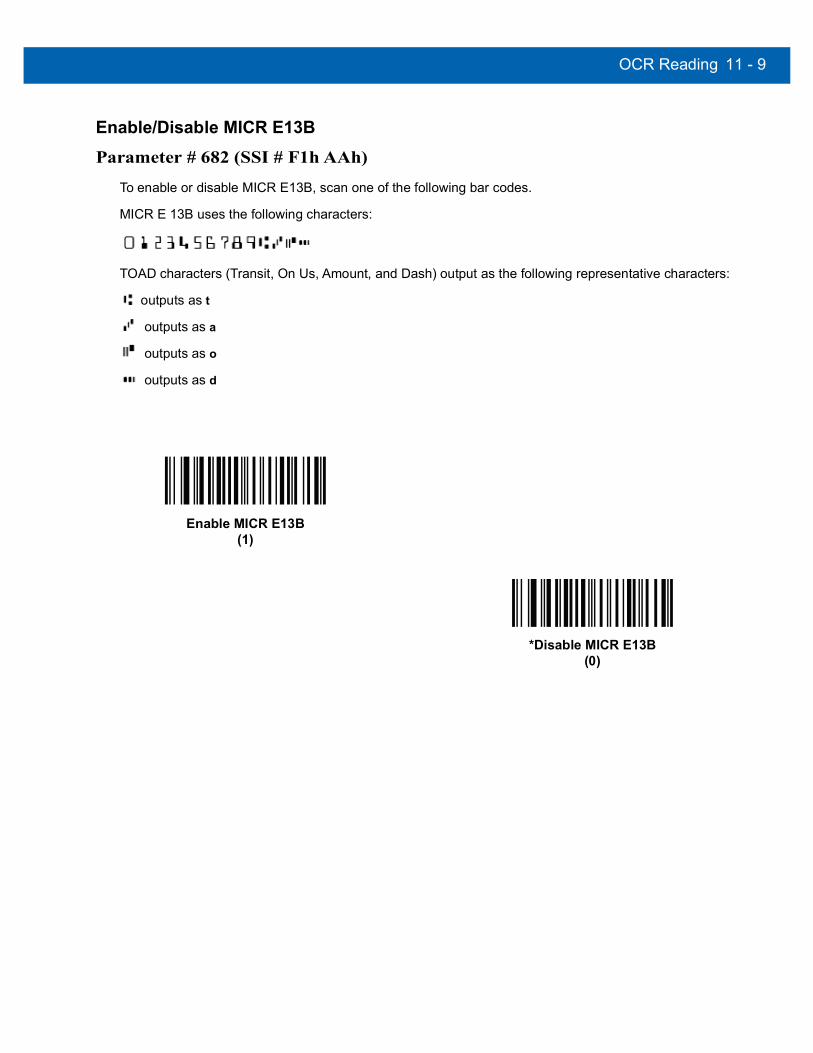
OCR Reading 11 - 9
Enable/Disable MICR E13B
Parameter # 682 (SSI # F1h AAh)
To enable or disable MICR E13B, scan one of the following bar codes.
MICR E 13B uses the following characters:
TOAD characters (Transit, On Us, Amount, and Dash) output as the following representative characters:
outputs as t
outputs as a
outputs as o
outputs as d
Enable MICR E13B(1)
*Disable MICR E13B(0)

11 - 10DS457 Fixed Mount Imager Integration Guide
Enable/Disable US Currency Serial Number
Parameter # 683 (SSI # F1 ABh)
To enable or disable US Currency Serial Number, scan one of the following bar codes.
OCR Orientation
Parameter # 687 (SSI # F1 AFh)
Select one of five options to specify the orientation of an OCR string to be read:
• 0o to the imaging engine (default)
• 270o clockwise (or 90o counterclockwise) to the imaging engine
• 180o (upside down) to the imaging engine
• 90o clockwise to the imaging engine
• Omnidirectional
Setting an incorrect orientation can cause misdecodes.
Enable US Currency(1)
*Disable US Currency(0)

OCR Reading11 - 11
OCR Orientation (continued)
*OCR Orientation 0o
(0)
OCR Orientation 270o Clockwise(1)
OCR Orientation 180o Clockwise(2)
OCR Orientation 90o Clockwise(3)
OCR Orientation Omnidirectional(4)

11 - 12DS457 Fixed Mount Imager Integration Guide
OCR Lines
Parameter # 691 (SSI # F1 B3h)
To select the number of OCR lines to decode, scan one of the following bar codes. Selecting Visas, Passport, TD1, or TD2 ID cards automatically sets the appropriate OCR Lines. Also see OCR-B Variant on page 11-6.
*OCR 1 Line(1)
OCR 2 Lines(2)
OCR 3 Lines(3)

OCR Reading11 - 13
OCR Minimum Characters
Parameter # 689 (SSI # F1 B1h)
To select the minimum number of OCR characters (not including spaces) per line to decode, scan the following bar code, then scan a three-digit number between 003 and 100 using the Numeric Keypad from the Advanced Data Formatting Programmer Guide representing the number of OCR characters to decode. Strings of OCR characters less than the minimum are ignored. The default is 003.
OCR Maximum Characters
Parameter # 690 (SSI # F1 B2h)
To select the maximum number of OCR characters (including spaces) per line to decode, scan the following bar code, then scan a three-digit number between 003 and 100 using the Numeric Keypad from the Advanced Data Formatting Programmer Guide representing the number of OCR characters to decode. Strings of OCR characters greater than the maximum are ignored. The default is 100.
OCR Security Level
Parameter # 554 (SSI # F1 2Ah)
To select the OCR decoding security/confidence level, scan the following bar code, then scan a two-digit number from the Numeric Keypad from the Advanced Data Formatting Programmer Guide representing the level of confidence. Greater numbers minimize OCR decoding errors but reduce performance. Setting a value that is too high can result in failure to decode. Setting a value that is too low can cause decoding errors. The range of the security level is 10 - 90 and the default is 80.
OCR Minimum Characters
OCR Maximum Characters
OCR Security Level

11 - 14DS457 Fixed Mount Imager Integration Guide
OCR Subset
Parameter # 686 (SSI # F1 AEh)
Set an OCR subset to define a custom group of characters in place of a preset font variant. For example, if scanning only numbers and the letters A, B, and C, create a subset of just these characters to speed decoding. This applies a designated OCR Subset across all enabled OCR fonts.
To set or modify the OCR font subset, first enable the appropriate OCR font(s). Next, scan the following bar code, then scan numbers and letters to form the OCR Subset from the Alphanumeric Keyboard from the Advanced Data Formatting Programmer Guide. Then scan End of Message from the Advanced Data Formatting Programmer Guide.
To cancel an OCR subset, for OCR-A or OCR-B, scan OCR-A variant Full ASCII, or OCR-B variant Full ASCII.
For MICR E13B or US Currency Serial Number, create a subset which includes all allowed characters in that character set, or scan an option from the Set Default Parameter on page 6-5 and re-program the imager.
OCR Quiet Zone
Parameter # 695 (SSI # F1h B7h)
This option sets the OCR quiet zone. The DS457 stops scanning a field when it detects a sufficiently wide blank space. The width of this space is defined by the End of Field option. Used with parsers that tolerate slanted characters, the End of Field count is roughly a count of 8 for a character width. For example if set to 15, then two character widths are an end of line indicator for the parser. Larger end of field numbers require bigger quiet zones at each end of text line.
To set a quiet zone, scan the following bar code, then scan a two-digit number using the Numeric Keypad from the Advanced Data Formatting Programmer Guide. The range of the quiet zone is 20 - 99 and the default is 50, indicating a six character width quiet zone.
OCR Subset
OCR Quiet Zone

OCR Reading11 - 15
OCR Bright Illumination
Parameter # 701 (SSI # F1h BDh)
When enabled, image contrast is improved for OCR scanning. Zebra recommends enabling this when the OCR string is longer than 20 characters, and for applications with busy backgrounds such as passport, check, or VISA reading.
Enable OCR Bright Illumination(1)
*Disable OCR Bright Illumination(0)
NOTE Enabling OCR Bright Illumination causes the aiming pattern to blink due to the lower frame rate setting.

11 - 16DS457 Fixed Mount Imager Integration Guide
OCR Template
Parameter # 547 (SSI # F1 23h)
This option creates a template for precisely matching scanned OCR characters to a desired input format. Carefully constructing an OCR template eliminates scanning errors.
To set or modify the OCR decode template, scan the OCR Template bar code, then bar codes corresponding to numbers and letters on the following pages to form the template expression. Then scan End of Message. The default is 54R which accepts any character OCR strings.
Required Digit (9)
Only a numeric character is allowed in this position.
Template Valid data Valid data Invalid data99999 12987 30517 123AB
Required Alpha (A)
Only an alpha character is allowed in this position.
Template Valid data Valid data Invalid dataAAA ABC WXY 12F
OCR Template
End of Message
9
A

OCR Reading11 - 17
Require and Suppress (0)It is required that any character in this position, including space or reject, is suppressed from the output.
Template Incoming data Output990AA 12QAB 12AB
Optional Alphanumeric (1)
When this option appears in the template string, the data validator accepts an alphanumeric character if present. Optional characters are not allowed as the first character(s) in a field of like characters.
Template Valid data Valid data Invalid data99991 1234A 12345 1234<
Optional Alpha (2)
When this option appears in the template string, the data validator accepts an alpha character if present. Optional characters are not allowed as the first character(s) in a field of like characters.
Template Valid data Valid data Invalid data AAAA2 ABCDE WXYZ ABCD6
Alpha or Digit (3)
The data validator requires an alphanumeric character in this position to validate the incoming data.
Template Valid data Valid data Invalid data33333 12ABC WXY34 12AB<
1
2
3

11 - 18DS457 Fixed Mount Imager Integration Guide
Any Including Space & Reject (4)
The template accepts any character in this position, including space and reject. Rejects are represented as an underscore (_) in the output. This is a good selection for troubleshooting.
Template Valid data Valid data 99499 12$34 34_98
Any except Space & Reject (5)
The template accepts any character in this position except a space or reject.
Template Valid data Valid data Invalid data 55999 A.123 *Z456 A BCD
Optional Digit (7)
When this option appears in the template string, the template accepts a numeric character if present. Optional characters are not allowed as the first character(s) in a field of like characters.
Template Valid data Valid data Invalid data99977 12345 789 789AB
4
5
7

OCR Reading11 - 19
Digit or Fill (8)
The data validator accepts any numeric or fill character in this position.
Template Valid data Valid data Invalid data88899 12345 >>789 <<789
Alpha or Fill (F)
The data validator accepts any alpha or fill character in this position.
Template Valid data Valid data Invalid dataAAAFF ABCXY LMN>> ABC<5
Required Space ( )
When this option appears in the template string, the template accepts a space if present. Optional characters are not allowed as the first character(s) in a field of like characters.
Template Valid data Invalid data99 99 12 34 67891
8
F
Space
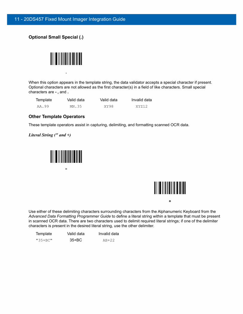
11 - 20DS457 Fixed Mount Imager Integration Guide
Optional Small Special (.)
When this option appears in the template string, the data validator accepts a special character if present. Optional characters are not allowed as the first character(s) in a field of like characters. Small special characters are - , and .
Template Valid data Valid data Invalid dataAA.99 MN.35 XY98 XYZ12
Other Template Operators These template operators assist in capturing, delimiting, and formatting scanned OCR data.
Literal String (" and +)
Use either of these delimiting characters surrounding characters from the Alphanumeric Keyboard from the Advanced Data Formatting Programmer Guide to define a literal string within a template that must be present in scanned OCR data. There are two characters used to delimit required literal strings; if one of the delimiter characters is present in the desired literal string, use the other delimiter.
Template Valid data Invalid data"35+BC" 35+BC AB+22
.
“
+

OCR Reading11 - 21
New Line (E)
To create a template of multiple lines, add E between the template of each single line.
Template Valid data Valid data Invalid data999EAAAA 321 987 XYZW
BCAD ZXYW 12
String Extract (C)
This operator combined with others defines a string of characters to extract from the scanned data. The string extract is structured as follows:
CbPe
Where:
• C is the string extract operator
• b is the string begin delimiter
• P is a single template character representing all string characters to be extracted
• e is the string end delimiter
Values for b and e can be any scannable character. They are included in the output stream.
Template Incoming data OutputC>A> XQ3>ABCDE> >ABCDE>
->ATHRUZ>123 >ATHRUZ>
1ABCZXYZ No Output
E
C
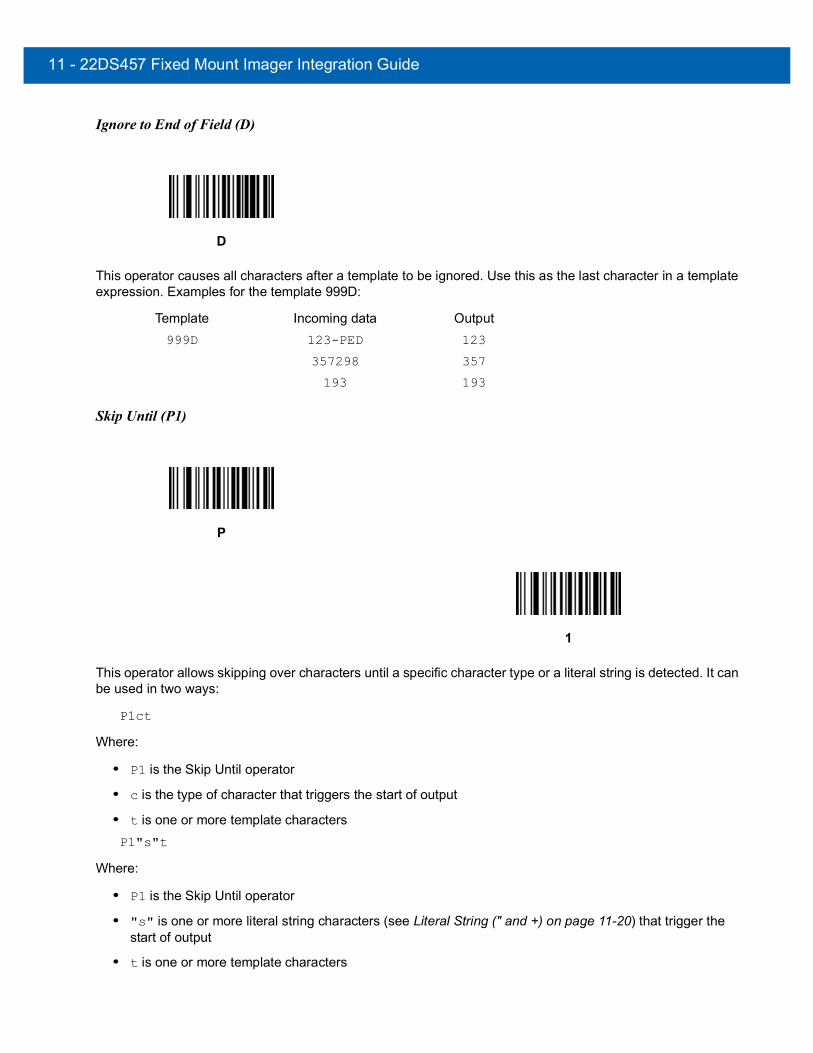
11 - 22DS457 Fixed Mount Imager Integration Guide
Ignore to End of Field (D)
This operator causes all characters after a template to be ignored. Use this as the last character in a template expression. Examples for the template 999D:
Template Incoming data Output999D 123-PED 123
357298 357
193 193
Skip Until (P1)
This operator allows skipping over characters until a specific character type or a literal string is detected. It can be used in two ways:
P1ct
Where:
• P1 is the Skip Until operator
• c is the type of character that triggers the start of output
• t is one or more template charactersP1"s"t
Where:
• P1 is the Skip Until operator
• "s" is one or more literal string characters (see Literal String (" and +) on page 11-20) that trigger the start of output
• t is one or more template characters
D
P
1

OCR Reading11 - 23
The trigger character or literal string is included in output from a Skip Until operator, and the first character in the template should accommodate this trigger.
Template Incoming data OutputP1"PN"AA9999 123PN9876 PN9876
PN1234 PN1234
X-PN3592 PN3592
Skip Until Not (P0)
This operator allows skipping over characters until a specific character type or a literal string is not matched in the output stream. It can be used in two ways:
P0ct
Where:
• P0 is the Skip Until Not operator
• c is the type of character that triggers the start of output
• t is one or more template charactersP0"s"t
Where:
• P0 is the Skip Until Not operator
• "s" is one or more literal string characters (see Literal String (" and +) on page 11-20) that trigger the start of output
• t is one or more template characters
P
0

11 - 24DS457 Fixed Mount Imager Integration Guide
The trigger character or literal string is not included in output from a Skip Until Not operator.
Template Incoming data OutputP0A9999 BPN3456 3456
PN1234 1234
5341 5341
Template Incoming data OutputP0"PN"9999 PN3456 3456
5341 5341
PNPN7654 7654
Repeat Previous (R)
This operator allows a template character to repeat one or more times, allowing the capture of variable-length scanned data. The following examples capture two required alpha characters followed by one or more required digits:
Template Incoming data OutputAA9R AB3 AB3
PN12345 PN12345
32RM52700 No output
Scroll Until Match (S)
This operator steps through scanned data one character at a time until the data matches the template.
Template Incoming data OutputS99999 AB3 No Output
PN12345 12345
32RM52700 52700
R
S

OCR Reading11 - 25
Multiple TemplatesThis feature sets up multiple templates for OCR decoding. To do this, follow the procedure described in OCR Template on page 11-16 (scan the OCR Template bar code, then bar codes corresponding to numbers and letters to form the template expression, then End of Message) for each template in the multiple template string, using a capital letter X as a separator between the templates.
For example, set the OCR Template as 99999XAAAAA to decode OCR strings of either 12345 or ABCDE.
Template ExamplesFollowing are sample templates with descriptions of valid data for each definition.
Field Definition Description"M"99977 M followed by three digits and two optional digits."X"997777"X" X followed by two digits, four optional digits, and an X.9959775599 Two digits followed by any character, a digit, two optional digits, any two
characters, and two digits.A55"-"999"-"99 A letter followed by two characters, a dash, three digits, a dash, and two digits.33A"."99 Two alphanumeric characters followed by a letter, a period, and two digits.999992991 Five digits followed by an optional alpha, two digits, and an optional alphanumeric."PN98" Literal field - PN98
OCR Check Digit Modulus
Parameter # 688 (SSI # F1h B0h)
This option sets OCR module check digit calculation. The check digit is the last digit (in the rightmost position) in an OCR string and improves the accuracy of the collected data. The check digit is the end product of a calculation made on the incoming data. For check digit calculation, for example Modulus 10, alpha and numeric characters are assigned numeric weights (see OCR Check Digit Multiplier on page 11-26). The calculation is applied to the character weights and the resulting check digit is added to the end of the data. If the incoming data does not match the check digit, the data is considered corrupt.
The selected check digit option does not take effect until you set OCR Check Digit Validation.
To choose the Check Digit Modulus, such as 10 for modulo 10, scan the following bar code, then scan a three-digit number from 001 to 099 representing the check digit using the Numeric Keypad from the Advanced Data Formatting Programmer Guide. The default is 1.
OCR Check Digit

11 - 26DS457 Fixed Mount Imager Integration Guide
OCR Check Digit Multiplier
Parameter # 700 (SSI # F1h BCh)
This option sets OCR check digit multipliers for the character positions. For check digit validation, each character in scanned data has an equivalent weight used in the check digit calculation. DS457 OCR ships with the following weight equivalents:
0 = 0 A = 10 K = 20 U = 301 = 1 B = 11 L = 21 V = 312 = 2 C = 12 M = 22 W = 323 = 3 D = 13 N = 23 X = 334 = 4 E = 14 O = 24 Y = 345 = 5 F = 15 P = 25 Z = 356 = 6 G = 16 Q = 26 Space = 07 = 7 H = 17 R = 278 = 8 I = 18 S = 289 = 9 J = 19 T = 29All other characters are equivalent to one (1).
You can define the multiplier string if it is different from the default.
121212121212 (default)123456789A (for ISBN, Product Add Right to Left. See OCR Check Digit Validation on page 11-27)
For example:
ISBN 0 2 0 1 1 8 3 9 9 4Multiplier 10 9 8 7 6 5 4 3 2 1Product 0 18 0 7 6 40 12 27 18 4Product add 0+ 18+ 0+ 7+ 6+ 40+ 12+ 27+ 18+ 4= 132
ISBN uses modulo 11 for its check digit. In this case, 132 is divisible by 11, so it passes the check digit.
To set the check digit multiplier, scan the following bar code, then scan numbers and letters to form the multiplier string from the Alphanumeric Keyboard from the Advanced Data Formatting Programmer Guide. Then scan End of Message from the Advanced Data Formatting Programmer Guide.
OCR Check Digit Multiplier

OCR Reading11 - 27
OCR Check Digit Validation
Parameter # 694 (SSI # F1h B6h)
Use OCR Check Digit Validation to protect against scanning errors by applying a check digit validation scheme. The following is a list of options.
NoneNo check digit validation, indicating no check digit is applied. This is the default.
Product Add Left to RightEach character in the scanned data is assigned a numeric value (see OCR Check Digit Multiplier on page 11-26). Each digit representing a character in the scanned data is multiplied by its corresponding digit in the multiplier, and the sum of these products is computed. The check digit passes if this sum modulo Check Digit Modulus is zero.
Example:
Scanned data numeric value is 132456 (check digit is 6)Check digit multiplier string is 123456
Digit 1 3 2 4 5 6Multiplier 1 2 3 4 5 6Product 1 6 6 16 25 36Product add 1+ 6+ 6+ 16+ 25+ 36= 90
The Check Digit Modulus is 10. It passes because 90 is divisible by 10 (the remainder is zero).
*No Check Digit(0)
Product Add Left to Right(3)

11 - 28DS457 Fixed Mount Imager Integration Guide
Product Add Right to LeftEach character in the scanned data is assigned a numeric value (see OCR Check Digit Multiplier on page 11-26). The check digit multiplier is reversed in order. Each value representing a character in the scanned data is multiplied by its corresponding digit in the reversed multiplier, resulting in a product for each character in the scanned data. The sum of these products is computed. The check digit passes if this sum modulo Check Digit Modulus is zero.
Example:
Scanned data numeric value is 132459 (check digit is 9)Check digit multiplier string is 123456
Digit 1 3 2 4 5 9Multiplier 6 5 4 3 2 1Product 6 15 8 12 10 9Product add 6+ 15+ 8+ 12+ 10+ 9= 60
The Check Digit Modulus is 10. It passes because 60 is divisible by 10 (the remainder is 0).
Digit Add Left to RightEach character in the scanned data is assigned a numeric value (see OCR Check Digit Multiplier on page 11-26). Each value representing a character in the scanned data is multiplied by its corresponding digit in the multiplier, resulting in a product for each character in the scanned data. The sum of each individual digit in all of the products is then calculated. The check digit passes if this sum modulo Check Digit Modulus is zero.
Example:
Scanned data numeric value is 132456 (check digit is 6)Check digit multiplier string is 123456
Digit 1 3 2 4 5 6Multiplier 1 2 3 4 5 6Product 1 6 6 16 25 36Digit add 1+ 6+ 6+ 1+6+ 2+5+ 3+6= 36
The Check Digit Modulus is 12. It passes because 36 is divisible by 12 (the remainder is 0).
Product Add Right to Left(1)
Digit Add Left to Right(4)

OCR Reading11 - 29
Digit Add Right to LeftEach character in the scanned data is assigned a numeric value (see OCR Check Digit Multiplier on page 11-26). The check digit multiplier is reversed in order. Each value representing a character in the scanned data is multiplied by its corresponding digit in the reversed multiplier, resulting in a product for each character in the scanned data. The sum of each individual digit in all of the products is then calculated. The check digit passes if this sum modulo Check Digit Modulus is zero.
Example:
Scanned data numeric value is 132456 (check digit is 6)Check digit multiplier string is 123456
Digit 1 3 2 4 5 6Multiplier 6 5 4 3 2 1Product 6 15 8 12 10 6Digit add 6+ 1+5+ 8+ 1+2+ 1+0+ 6= 30
The Check Digit Modulus is 10. It passes because 30 is divisible by 10 (the remainder is 0).
Product Add Right to Left Simple RemainderEach character in the scanned data is assigned a numeric value (see OCR Check Digit Multiplier on page 11-26). The check digit multiplier is reversed in order. Each value representing a character in the scanned data is multiplied by its corresponding digit in the reversed multiplier, resulting in a product for each character in the scanned data. The sum of these products except for the check digit's product is computed. The check digit passes if this sum modulo Check Digit Modulus is equal to the check digit's product.
Example:
Scanned data numeric value is 122456 (check digit is 6)Check digit multiplier string is 123456
Digit 1 2 2 4 5 6Multiplier 6 5 4 3 2 1Product 6 10 8 12 10 6Product add 6+ 10+ 8+ 12+ 10= 46 6
The Check Digit Modulus is 10. It passes because 46 divided by 10 leaves a remainder of 6.
Digit Add Right to Left(2)
Product Add Right to Left Simple Remainder(5)
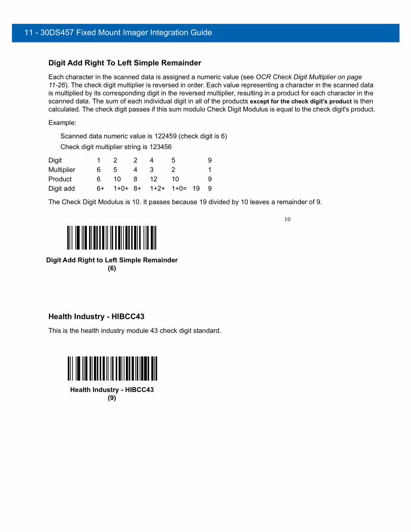
11 - 30DS457 Fixed Mount Imager Integration Guide
Digit Add Right To Left Simple RemainderEach character in the scanned data is assigned a numeric value (see OCR Check Digit Multiplier on page 11-26). The check digit multiplier is reversed in order. Each value representing a character in the scanned data is multiplied by its corresponding digit in the reversed multiplier, resulting in a product for each character in the scanned data. The sum of each individual digit in all of the products except for the check digit's product is then calculated. The check digit passes if this sum modulo Check Digit Modulus is equal to the check digit's product.
Example:
Scanned data numeric value is 122459 (check digit is 6)Check digit multiplier string is 123456
Digit 1 2 2 4 5 9Multiplier 6 5 4 3 2 1Product 6 10 8 12 10 9Digit add 6+ 1+0+ 8+ 1+2+ 1+0= 19 9
The Check Digit Modulus is 10. It passes because 19 divided by 10 leaves a remainder of 9.
Health Industry - HIBCC43This is the health industry module 43 check digit standard.
Digit Add Right to Left Simple Remainder(6)
10
Health Industry - HIBCC43(9)
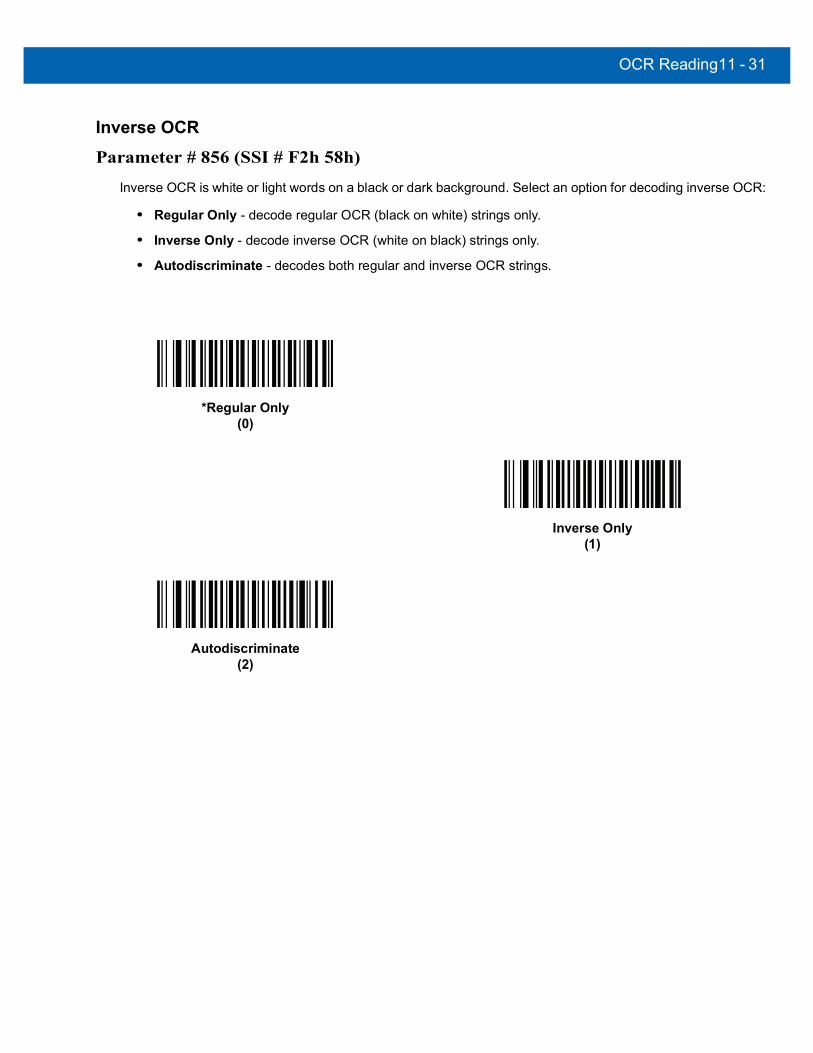
OCR Reading11 - 31
Inverse OCR
Parameter # 856 (SSI # F2h 58h)
Inverse OCR is white or light words on a black or dark background. Select an option for decoding inverse OCR:
• Regular Only - decode regular OCR (black on white) strings only.
• Inverse Only - decode inverse OCR (white on black) strings only.
• Autodiscriminate - decodes both regular and inverse OCR strings.
*Regular Only(0)
Inverse Only(1)
Autodiscriminate(2)

11 - 32DS457 Fixed Mount Imager Integration Guide

CHAPTER 12SYMBOLOGIES
IntroductionThis chapter describes symbology features and provides the programming bar codes for selecting these features. Before programming, follow the instructions in Chapter 1, Getting Started.
The imager is shipped with the settings shown in the Symbology Default Table on page 12-2 (also see Appendix A, Standard Default Parameters for all host device and miscellaneous defaults). If the default values suit requirements, programming is not necessary.
There are two ways to change a parameter value:
• Scan the appropriate bar codes in this guide. These new values replace the standard default values in memory.
• For SSI and USB SNAPI hosts, send a “parameter send” command from the host system. Hexadecimal parameter numbers are shown in this chapter below the parameter title, and options are shown in parenthesis beneath the accompanying bar codes. See the Simple Serial Interface (SSI) Programmer’s Guide for detailed instructions for changing parameter values using this method.
To return all features to default values, scan Set Default Parameter on page 6-5. Throughout the programming bar code menus, default values are indicated with asterisks (*).
NOTE Most computer monitors allow scanning the bar codes directly on the screen. When scanning from the screen, be sure to set the document magnification to a level where the bar code can be seen clearly, and bars and/or spaces are not merging.
*Enable UPC-A(0) Feature’/Option* Indicates Default

12 - 2 DS457 Fixed Mount Imager Integration Guide
Scanning Sequence ExamplesIn most cases, scanning one bar code sets the parameter value. For example, to transmit bar code data without the UPC-A check digit, simply scan the Do Not Transmit UPC-A Check Digit bar code under Transmit UPC-A Check Digit on page 12-17. The imager issues a fast warble beep and the LED turns green, signifying a successful parameter entry.
Other parameters, such as Set Length(s) for D 2 of 5 require scanning several bar codes. See the individual parameter, such as Set Length(s) for D 2 of 5, for this procedure.
Errors While ScanningUnless otherwise specified, to correct an error during a scanning sequence, just re-scan the correct parameter.
Symbology Parameter DefaultsTable 12-1 lists the defaults for all symbologies parameters. To change any option, scan the appropriate bar code(s) provided in the Symbologies Parameters section beginning on page 12-9.
NOTE See Appendix A, Standard Default Parameters for all user preferences, hosts, and miscellaneous default parameters.
Table 12-1 Symbology Default Table
Parameter Parameter Number
SSI Number Default Page
Number
Disable All Symbologies N/A N/A N/A 12-8
UPC/EAN
UPC-A 1 01h Enable 12-9
UPC-E 2 02h Enable 12-9
UPC-E1 12 0Ch Disable 12-10
EAN-8/JAN 8 4 04h Enable 12-10
EAN-13/JAN 13 3 03h Enable 12-11
Bookland EAN 83 53h Disable 12-11
Decode UPC/EAN/JAN Supplementals (2 and 5 digits)
16 10h Ignore 12-12
User-Programmable SupplementalsSupplemental 1: Supplemental 2:
579580
F1h 43hF1h 44h
12-15
UPC/EAN/JAN Supplemental Redundancy 80 50h 10 12-15
UPC/EAN/JAN Supplemental AIM ID Format 672 F1h A0h Combined 12-16
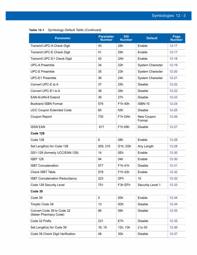
Symbologies 12 - 3
Transmit UPC-A Check Digit 40 28h Enable 12-17
Transmit UPC-E Check Digit 41 29h Enable 12-17
Transmit UPC-E1 Check Digit 42 2Ah Enable 12-18
UPC-A Preamble 34 22h System Character 12-19
UPC-E Preamble 35 23h System Character 12-20
UPC-E1 Preamble 36 24h System Character 12-21
Convert UPC-E to A 37 25h Disable 12-22
Convert UPC-E1 to A 38 26h Disable 12-22
EAN-8/JAN-8 Extend 39 27h Disable 12-23
Bookland ISBN Format 576 F1h 40h ISBN-10 12-24
UCC Coupon Extended Code 85 55h Disable 12-25
Coupon Report 730 F1h DAh New Coupon Format
12-26
ISSN EAN 617 F1h 69h Disable 12-27
Code 128
Code 128 8 08h Enable 12-28
Set Length(s) for Code 128 209, 210 D1h, D2h Any Length 12-28
GS1-128 (formerly UCC/EAN-128) 14 0Eh Enable 12-30
ISBT 128 84 54h Enable 12-30
ISBT Concatenation 577 F1h 41h Disable 12-31
Check ISBT Table 578 F1h 42h Enable 12-32
ISBT Concatenation Redundancy 223 DFh 10 12-32
Code 128 Security Level 751 F3h EFh Security Level 1 12-33
Code 39
Code 39 0 00h Enable 12-34
Trioptic Code 39 13 0Dh Disable 12-34
Convert Code 39 to Code 32 (Italian Pharmacy Code)
86 56h Disable 12-35
Code 32 Prefix 231 E7h Disable 12-35
Set Length(s) for Code 39 18, 19 12h, 13h 2 to 55 12-36
Code 39 Check Digit Verification 48 30h Disable 12-37
Table 12-1 Symbology Default Table (Continued)
Parameter Parameter Number
SSI Number Default Page
Number

12 - 4 DS457 Fixed Mount Imager Integration Guide
Transmit Code 39 Check Digit 43 2Bh Disable 12-48
Code 39 Full ASCII Conversion 17 11h Disable 12-38
Buffer Code 39 113 71h Disable 12-39
Code 39 Security Level 750 F3h EEh Security Level 1 12-42
Code 93
Code 93 9 09h Disable 12-43
Set Length(s) for Code 93 26, 27 1Ah, 1Bh 4 to 55 12-43
Code 11
Code 11 10 0Ah Disable 12-45
Set Lengths for Code 11 28, 29 1Ch, 1Dh 4 to 55 12-45
Code 11 Check Digit Verification 52 34h Disable 12-47
Transmit Code 11 Check Digit(s) 47 2Fh Disable 12-48
Interleaved 2 of 5 (ITF)
Interleaved 2 of 5 (ITF) 6 06h Enable 12-48
Set Lengths for I 2 of 5 22, 23 16h, 17h Range 6 - 55 12-49
I 2 of 5 Check Digit Verification 49 31h Disable 12-50
Transmit I 2 of 5 Check Digit 44 2Ch Disable 12-51
Convert I 2 of 5 to EAN 13 82 52h Disable 12-51
I 2 of 5 Security Level 1121 Security Level 1 12-52
Discrete 2 of 5 (DTF)
Discrete 2 of 5 5 05h Disable 12-53
Set Length(s) for D 2 of 5 20, 21 14h 15h 12 12-53
Codabar (NW - 7)
Codabar 7 07h Disable 12-55
Set Lengths for Codabar 24, 25 18h, 19h 5 to 55 12-55
CLSI Editing 54 36h Disable 12-57
NOTIS Editing 55 37h Disable 12-57
Codabar Upper or Lower Case Start/Stop Characters Transmission
855 F2h 57h Upper Case 12-58
Table 12-1 Symbology Default Table (Continued)
Parameter Parameter Number
SSI Number Default Page
Number

Symbologies 12 - 5
MSI
MSI 11 0Bh Disable 12-59
Set Length(s) for MSI 30, 31 1Eh, 1Fh 4 to 55 12-59
MSI Check Digits 50 32h One 12-61
Transmit MSI Check Digit 46 2Eh Disable 12-62
MSI Check Digit Algorithm 51 33h Mod 10/Mod 10 12-62
Chinese 2 of 5
Chinese 2 of 5 408 F0h 98h Disable 12-63
Matrix 2 of 5
Matrix 2 of 5 618 F1h 6Ah Disable 12-63
Matrix 2 of 5 Lengths 619, 620 F1h 6BhF1h 6Ch
1 Length: 14 12-64
Matrix 2 of 5 Check Digit 622 F1h 6Eh Disable 12-65
Transmit Matrix 2 of 5 Check Digit 623 F1h 6Fh Disable 12-65
Korean 3 of 5
Korean 3 of 5 581 F1h 45h Disable 12-66
Inverse 1D 586 F1h 4Ah DS457-SR/HD/DL: RegularDS457-DP: Inverse Autodetect
12-67
Postal Codes
US Postnet 89 59h Disable 12-68
US Planet 90 5Ah Disable 12-68
Transmit US Postal Check Digit 95 5Fh Enable 12-69
UK Postal 91 5Bh Disable 12-69
Transmit UK Postal Check Digit 96 60h Enable 12-70
Japan Postal 290 F0h 22h Disable 12-70
Australia Post 291 F0h 23h Disable 12-71
Australia Post Format 718 F1h CEh Autodiscriminate 12-72
Netherlands KIX Code 326 F0h 46h Disable 12-73
USPS 4CB/One Code/Intelligent Mail 592 F1h 50h Disable 12-74
UPU FICS Postal 611 F1h 63h Disable 12-74
Table 12-1 Symbology Default Table (Continued)
Parameter Parameter Number
SSI Number Default Page
Number
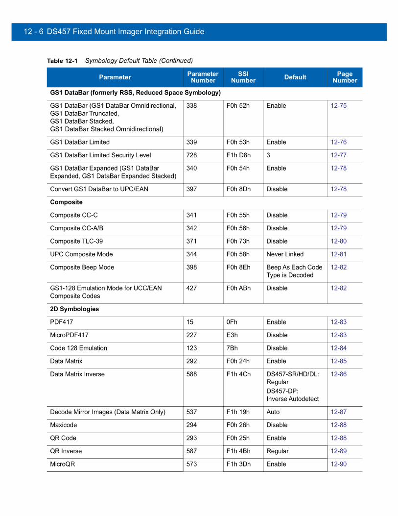
12 - 6 DS457 Fixed Mount Imager Integration Guide
GS1 DataBar (formerly RSS, Reduced Space Symbology)
GS1 DataBar (GS1 DataBar Omnidirectional, GS1 DataBar Truncated, GS1 DataBar Stacked, GS1 DataBar Stacked Omnidirectional)
338 F0h 52h Enable 12-75
GS1 DataBar Limited 339 F0h 53h Enable 12-76
GS1 DataBar Limited Security Level 728 F1h D8h 3 12-77
GS1 DataBar Expanded (GS1 DataBar Expanded, GS1 DataBar Expanded Stacked)
340 F0h 54h Enable 12-78
Convert GS1 DataBar to UPC/EAN 397 F0h 8Dh Disable 12-78
Composite
Composite CC-C 341 F0h 55h Disable 12-79
Composite CC-A/B 342 F0h 56h Disable 12-79
Composite TLC-39 371 F0h 73h Disable 12-80
UPC Composite Mode 344 F0h 58h Never Linked 12-81
Composite Beep Mode 398 F0h 8Eh Beep As Each Code Type is Decoded
12-82
GS1-128 Emulation Mode for UCC/EAN Composite Codes
427 F0h ABh Disable 12-82
2D Symbologies
PDF417 15 0Fh Enable 12-83
MicroPDF417 227 E3h Disable 12-83
Code 128 Emulation 123 7Bh Disable 12-84
Data Matrix 292 F0h 24h Enable 12-85
Data Matrix Inverse 588 F1h 4Ch DS457-SR/HD/DL: RegularDS457-DP: Inverse Autodetect
12-86
Decode Mirror Images (Data Matrix Only) 537 F1h 19h Auto 12-87
Maxicode 294 F0h 26h Disable 12-88
QR Code 293 F0h 25h Enable 12-88
QR Inverse 587 F1h 4Bh Regular 12-89
MicroQR 573 F1h 3Dh Enable 12-90
Table 12-1 Symbology Default Table (Continued)
Parameter Parameter Number
SSI Number Default Page
Number

Symbologies 12 - 7
Aztec 574 F1h 3Eh Enable 12-90
Aztec Inverse 589 F1h 4Dh Inverse Autodetect 12-91
Symbology-Specific Security Levels
Redundancy Level 78 4Eh 1 12-92
Security Level 77 4Dh 1 12-94
Intercharacter Gap Size 381 F0h 7Dh Normal 12-95
Macro PDF
Macro PDF Transmit/Decode Mode Symbols 188 BCh Passthrough Mode 12-97
Transmit Macro PDF Control Header 184 B8h Disable 12-98
Escape Characters 233 E9h N/A 12-98
Flush Macro PDF Buffer N/A N/A N/A 12-99
Abort Macro PDF Entry N/A N/A N/A 12-99
Table 12-1 Symbology Default Table (Continued)
Parameter Parameter Number
SSI Number Default Page
Number

12 - 8 DS457 Fixed Mount Imager Integration Guide
Disable All SymbologiesScan the bar code below to disable the decoding of all symbologies. Use this to simplify selecting a single symbology to decode by scanning this, then scanning the desired enable code type bar code. Note that the imager can still decode parameter bar codes.
Disable All Symbologies
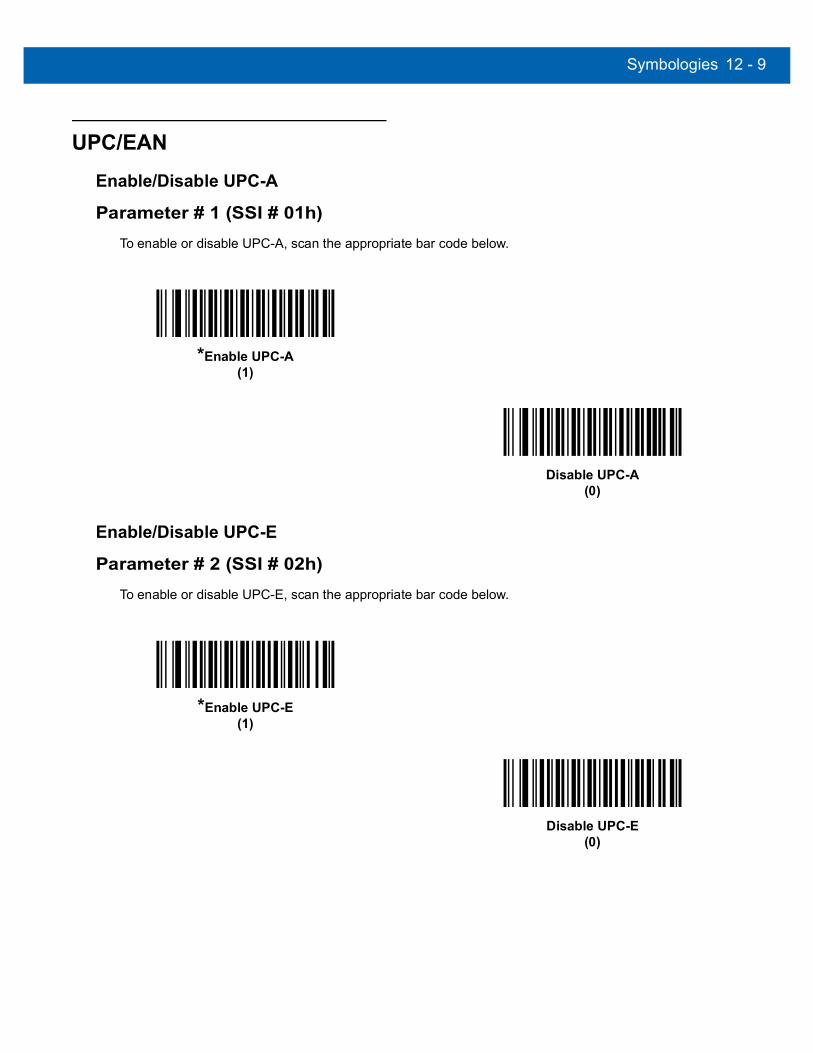
Symbologies 12 - 9
UPC/EAN
Enable/Disable UPC-A
Parameter # 1 (SSI # 01h)To enable or disable UPC-A, scan the appropriate bar code below.
Enable/Disable UPC-E
Parameter # 2 (SSI # 02h)To enable or disable UPC-E, scan the appropriate bar code below.
*Enable UPC-A(1)
Disable UPC-A(0)
*Enable UPC-E(1)
Disable UPC-E(0)

12 - 10DS457 Fixed Mount Imager Integration Guide
Enable/Disable UPC-E1
Parameter # 12 (SSI # 0Ch)UPC-E1 is disabled by default.
To enable or disable UPC-E1, scan the appropriate bar code below.
Enable/Disable EAN-8/JAN-8
Parameter # 4 (SSI # 04h)To enable or disable EAN-8/JAN-8, scan the appropriate bar code below.
NOTE UPC-E1 is not a UCC (Uniform Code Council) approved symbology.
Enable UPC-E1(1)
*Disable UPC-E1(0)
*Enable EAN-8/JAN-8(1)
Disable EAN-8/JAN-8(0)
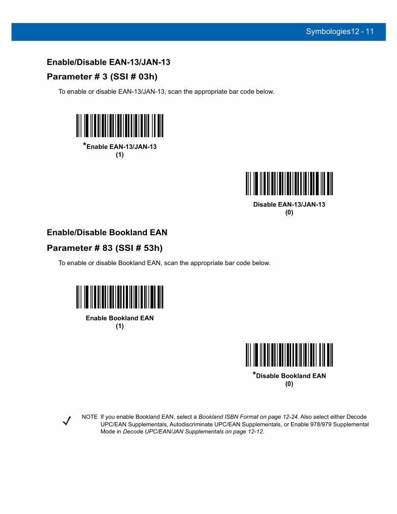
Symbologies12 - 11
Enable/Disable EAN-13/JAN-13
Parameter # 3 (SSI # 03h)To enable or disable EAN-13/JAN-13, scan the appropriate bar code below.
Enable/Disable Bookland EAN
Parameter # 83 (SSI # 53h)To enable or disable Bookland EAN, scan the appropriate bar code below.
*Enable EAN-13/JAN-13(1)
Disable EAN-13/JAN-13(0)
Enable Bookland EAN (1)
*Disable Bookland EAN(0)
NOTE If you enable Bookland EAN, select a Bookland ISBN Format on page 12-24. Also select either Decode UPC/EAN Supplementals, Autodiscriminate UPC/EAN Supplementals, or Enable 978/979 Supplemental Mode in Decode UPC/EAN/JAN Supplementals on page 12-12.

12 - 12DS457 Fixed Mount Imager Integration Guide
Decode UPC/EAN/JAN Supplementals
Parameter # 16 (SSI # 10h)Supplementals are bar codes appended according to specific format conventions (e.g., UPC A+2, UPC E+2, EAN 13+2). The following options are available:
• If you select Ignore UPC/EAN with Supplementals, and the imager is presented with a UPC/EAN plus supplemental symbol, the imager decodes UPC/EAN and ignores the supplemental characters.
• If you select Decode UPC/EAN with Supplementals, the imager only decodes UPC/EAN symbols with supplemental characters, and ignores symbols without supplementals.
• If you select Autodiscriminate UPC/EAN Supplementals, the imager decodes UPC/EAN symbols with supplemental characters immediately. If the symbol does not have a supplemental, the imager must decode the bar code the number of times set via UPC/EAN/JAN Supplemental Redundancy on page 12-15 before transmitting its data to confirm that there is no supplemental.
• If you select one of the following Supplemental Mode options, the imager immediately transmits EAN-13 bar codes starting with that prefix that have supplemental characters. If the symbol does not have a supplemental, the imager must decode the bar code the number of times set via UPC/EAN/JAN Supplemental Redundancy on page 12-15 before transmitting its data to confirm that there is no supplemental. The imager transmits UPC/EAN bar codes that do not have that prefix immediately.• Enable 378/379 Supplemental Mode• Enable 978/979 Supplemental Mode.
• Enable 977 Supplemental Mode• Enable 414/419/434/439 Supplemental Mode• Enable 491 Supplemental Mode• Enable Smart Supplemental Mode - applies to EAN-13 bar codes starting with any prefix listed
previously.• Supplemental User-Programmable Type 1 - applies to EAN-13 bar codes starting with a 3-digit
user-defined prefix. Set this 3-digit prefix using User-Programmable Supplementals on page 12-15.• Supplemental User-Programmable Type 1 and 2 - applies to EAN-13 bar codes starting with either
of two 3-digit user-defined prefixes. Set the 3-digit prefixes using User-Programmable Supplementals on page 12-15.
• Smart Supplemental Plus User-Programmable 1 - applies to EAN-13 bar codes starting with any prefix listed previously or the user-defined prefix set using User-Programmable Supplementals on page 12-15.
• Smart Supplemental Plus User-Programmable 1 and 2 - applies to EAN-13 bar codes starting with any prefix listed previously or one of the two user-defined prefixes set using User-Programmable Supplementals on page 12-15.
NOTE If you select 978 Supplemental Mode and are scanning Bookland EAN bar codes, see Enable/Disable Bookland EAN on page 12-11 to enable Bookland EAN, and select a format using Bookland ISBN Format on page 12-24.
NOTE To minimize the risk of invalid data transmission, select either to decode or ignore supplemental characters.

Symbologies12 - 13
Decode UPC/EAN/JAN Supplementals (continued)
Decode UPC/EAN/JAN Only With Supplementals(1)
*Ignore Supplementals(0)
Autodiscriminate UPC/EAN/JAN Supplementals(2)
Enable 378/379 Supplemental Mode(4)
Enable 978/979 Supplemental Mode(5)
Enable 977 Supplemental Mode(7)
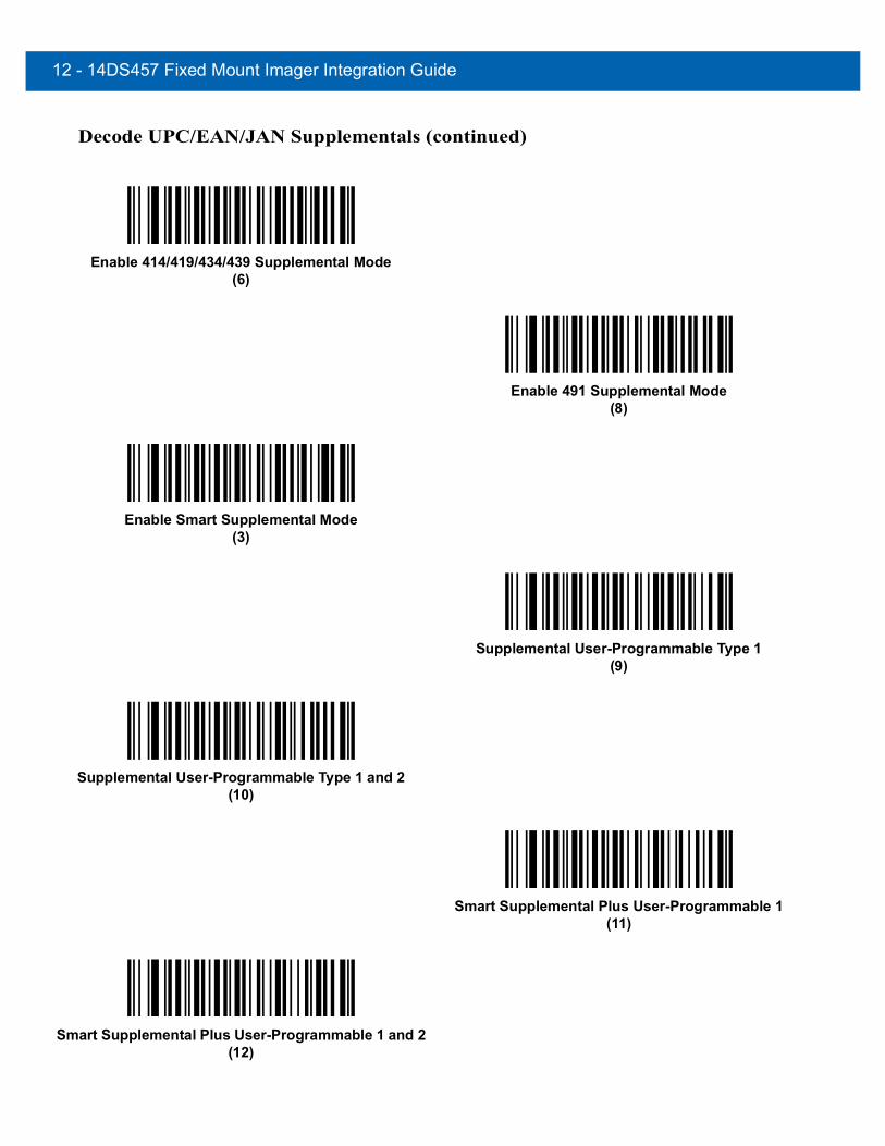
12 - 14DS457 Fixed Mount Imager Integration Guide
Decode UPC/EAN/JAN Supplementals (continued)
Enable 414/419/434/439 Supplemental Mode(6)
Enable 491 Supplemental Mode(8)
Enable Smart Supplemental Mode(3)
Supplemental User-Programmable Type 1(9)
Supplemental User-Programmable Type 1 and 2(10)
Smart Supplemental Plus User-Programmable 1(11)
Smart Supplemental Plus User-Programmable 1 and 2(12)
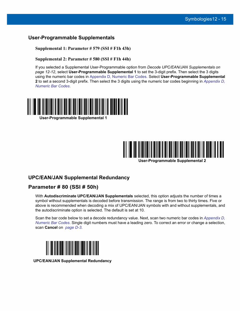
Symbologies12 - 15
User-Programmable Supplementals
Supplemental 1: Parameter # 579 (SSI # F1h 43h)
Supplemental 2: Parameter # 580 (SSI # F1h 44h)
If you selected a Supplemental User-Programmable option from Decode UPC/EAN/JAN Supplementals on page 12-12, select User-Programmable Supplemental 1 to set the 3-digit prefix. Then select the 3 digits using the numeric bar codes in Appendix D, Numeric Bar Codes. Select User-Programmable Supplemental 2 to set a second 3-digit prefix. Then select the 3 digits using the numeric bar codes beginning in Appendix D, Numeric Bar Codes.
UPC/EAN/JAN Supplemental Redundancy
Parameter # 80 (SSI # 50h)With Autodiscriminate UPC/EAN/JAN Supplementals selected, this option adjusts the number of times a symbol without supplementals is decoded before transmission. The range is from two to thirty times. Five or above is recommended when decoding a mix of UPC/EAN/JAN symbols with and without supplementals, and the autodiscriminate option is selected. The default is set at 10.
Scan the bar code below to set a decode redundancy value. Next, scan two numeric bar codes in Appendix D, Numeric Bar Codes. Single digit numbers must have a leading zero. To correct an error or change a selection, scan Cancel on page D-3.
User-Programmable Supplemental 1
User-Programmable Supplemental 2
UPC/EAN/JAN Supplemental Redundancy

12 - 16DS457 Fixed Mount Imager Integration Guide
UPC/EAN/JAN Supplemental AIM ID Format
Parameter # 672 (SSI # F1h A0h)
Select an output format when reporting UPC/EAN/JAN bar codes with Supplementals with Transmit Code ID Character on page 6-37 set to AIM Code ID Character:
• Separate - transmit UPC/EAN with supplementals with separate AIM IDs but one transmission, i.e.:]E<0 or 4><data>]E<1 or 2>[supplemental data]
• Combined – transmit UPC/EAN with supplementals with one AIM ID and one transmission, i.e.:]E3<data+supplemental data>
• Separate Transmissions - transmit UPC/EAN with supplementals with separate AIM IDs and separate transmissions, i.e.:
]E<0 or 4><data>]E<1 or 2>[supplemental data]
Separate(0)
*Combined(1)
Separate Transmissions(2)

Symbologies12 - 17
Transmit UPC-A Check Digit
Parameter # 40 (SSI # 28h)The check digit is the last character of the symbol used to verify the integrity of the data. Scan the appropriate bar code below to transmit the bar code data with or without the UPC-A check digit. It is always verified to guarantee the integrity of the data.
Transmit UPC-E Check Digit
Parameter # 41 (SSI # 29h)The check digit is the last character of the symbol used to verify the integrity of the data. Scan the appropriate bar code below to transmit the bar code data with or without the UPC-E check digit. It is always verified to guarantee the integrity of the data.
*Transmit UPC-A Check Digit(1)
Do Not Transmit UPC-A Check Digit(0)
*Transmit UPC-E Check Digit(1)
Do Not Transmit UPC-E Check Digit(0)
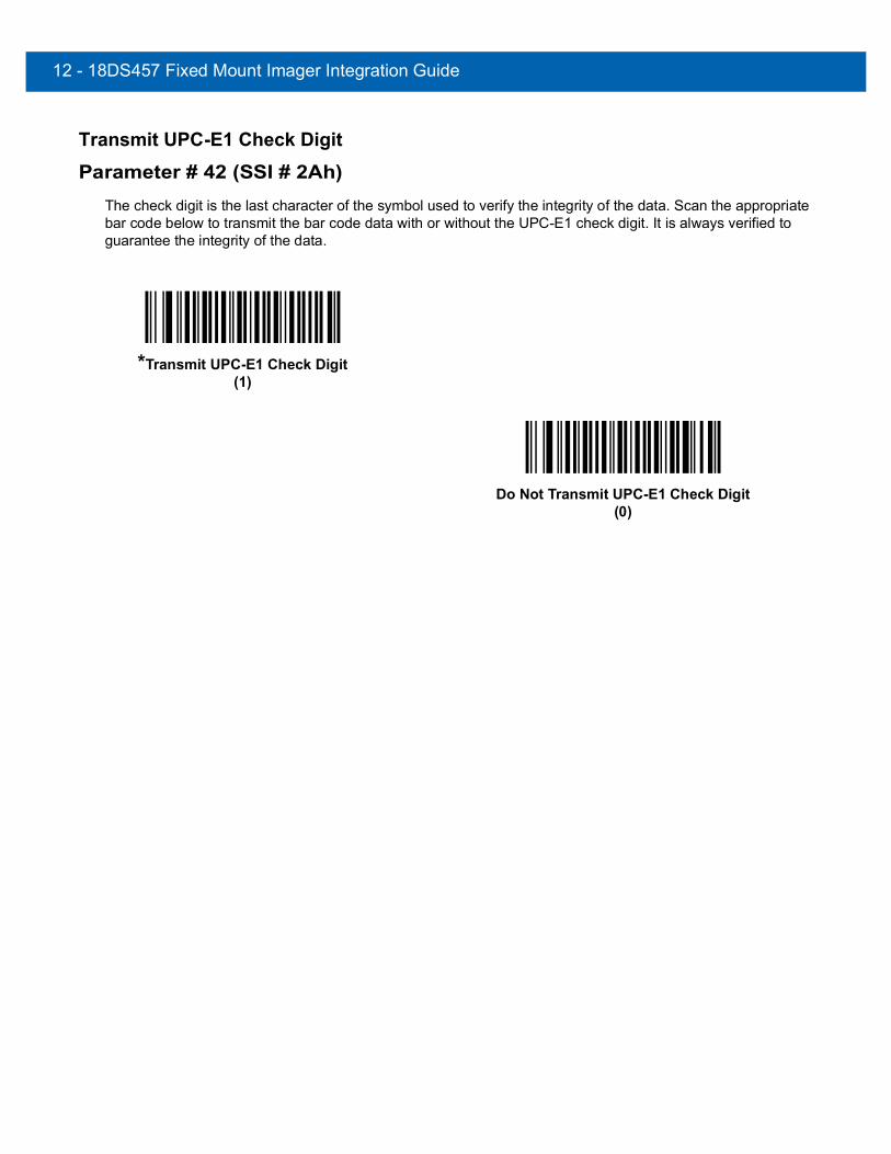
12 - 18DS457 Fixed Mount Imager Integration Guide
Transmit UPC-E1 Check Digit
Parameter # 42 (SSI # 2Ah)The check digit is the last character of the symbol used to verify the integrity of the data. Scan the appropriate bar code below to transmit the bar code data with or without the UPC-E1 check digit. It is always verified to guarantee the integrity of the data.
*Transmit UPC-E1 Check Digit(1)
Do Not Transmit UPC-E1 Check Digit(0)

Symbologies12 - 19
UPC-A Preamble
Parameter # 34 (SSI # 22h)Preamble characters are part of the UPC symbol, and include Country Code and System Character. There are three options for transmitting a UPC-A preamble to the host device: transmit System Character only, transmit System Character and Country Code (“0” for USA), and transmit no preamble. Select the appropriate option to match the host system.
No Preamble (<DATA>)(0)
*System Character (<SYSTEM CHARACTER> <DATA>)
(1)
System Character & Country Code(< COUNTRY CODE> <SYSTEM CHARACTER>
<DATA>)(2)

12 - 20DS457 Fixed Mount Imager Integration Guide
UPC-E Preamble
Parameter # 35 (SSI # 23h)Preamble characters are part of the UPC symbol, and include Country Code and System Character. There are three options for transmitting a UPC-E preamble to the host device: transmit System Character only, transmit System Character and Country Code (“0” for USA), and transmit no preamble. Select the appropriate option to match the host system.
No Preamble (<DATA>)(0)
*System Character (<SYSTEM CHARACTER> <DATA>)
(1)
System Character & Country Code(< COUNTRY CODE> <SYSTEM CHARACTER>
<DATA>)(2)
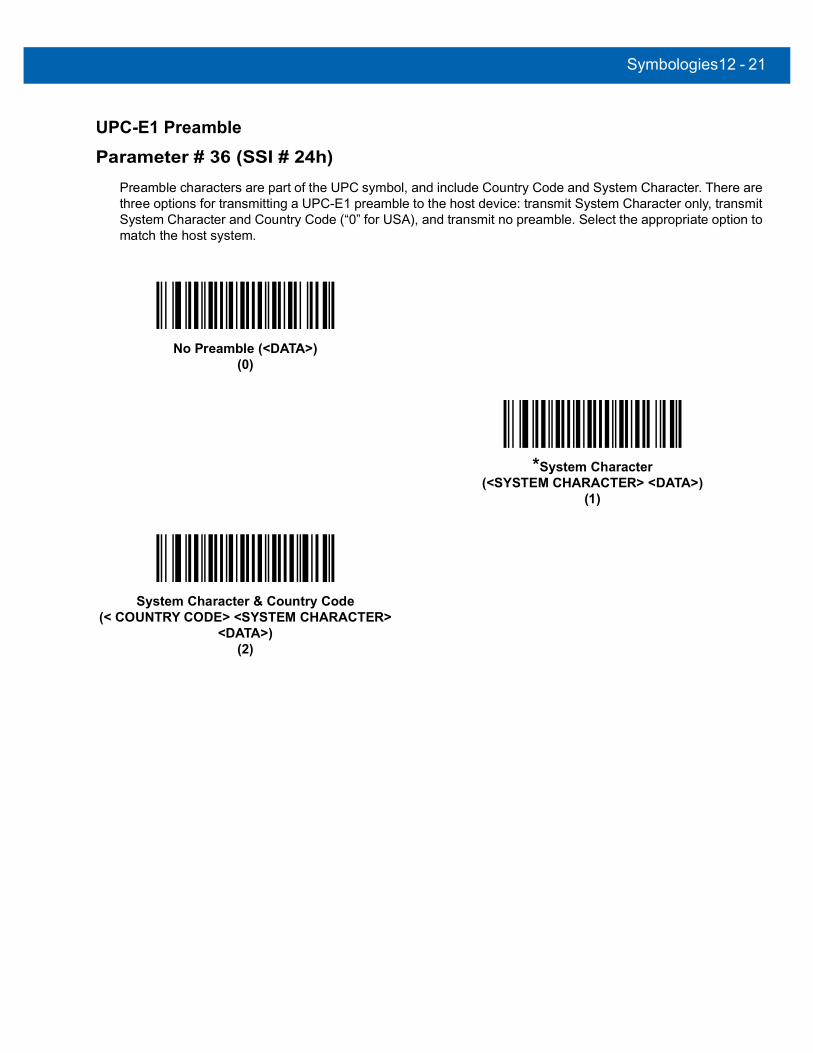
Symbologies12 - 21
UPC-E1 Preamble
Parameter # 36 (SSI # 24h)Preamble characters are part of the UPC symbol, and include Country Code and System Character. There are three options for transmitting a UPC-E1 preamble to the host device: transmit System Character only, transmit System Character and Country Code (“0” for USA), and transmit no preamble. Select the appropriate option to match the host system.
No Preamble (<DATA>)(0)
*System Character (<SYSTEM CHARACTER> <DATA>)
(1)
System Character & Country Code(< COUNTRY CODE> <SYSTEM CHARACTER>
<DATA>)(2)

12 - 22DS457 Fixed Mount Imager Integration Guide
Convert UPC-E to UPC-A
Parameter # 37 (SSI # 25h)Enable this to convert UPC-E (zero suppressed) decoded data to UPC-A format before transmission. After conversion, the data follows UPC-A format and is affected by UPC-A programming selections (e.g., Preamble, Check Digit).
When disabled, UPC-E decoded data is transmitted as UPC-E data, without conversion.
Convert UPC-E1 to UPC-A
Parameter # 38 (SSI # 26h)Enable this to convert UPC-E1 decoded data to UPC-A format before transmission. After conversion, the data follows UPC-A format and is affected by UPC-A programming selections (e.g., Preamble, Check Digit).
When disabled, UPC-E1 decoded data is transmitted as UPC-E1 data, without conversion.
Convert UPC-E to UPC-A (Enable)(1)
*Do Not Convert UPC-E to UPC-A (Disable)(0)
Convert UPC-E1 to UPC-A (Enable)(1)
*Do Not Convert UPC-E1 to UPC-A (Disable)(0)

Symbologies12 - 23
EAN-8/JAN-8 Extend
Parameter # 39 (SSI # 27h)When enabled, this parameter adds five leading zeros to decoded EAN-8 symbols to make them compatible in format to EAN-13 symbols.
When disabled, EAN-8 symbols are transmitted as is.
Enable EAN/JAN Zero Extend(1)
*Disable EAN/JAN Zero Extend(0)

12 - 24DS457 Fixed Mount Imager Integration Guide
Bookland ISBN Format
Parameter # 576 (SSI # F1h 40h)If you enabled Bookland EAN using Enable/Disable Bookland EAN on page 12-11, select one of the following formats for Bookland data:
• Bookland ISBN-10 - The imager reports Bookland data starting with 978 in traditional 10-digit format with the special Bookland check digit for backward-compatibility. Data starting with 979 is not considered Bookland in this mode.
• Bookland ISBN-13 - The imager reports Bookland data (starting with either 978 or 979) as EAN-13 in 13-digit format to meet the 2007 ISBN-13 protocol.
*Bookland ISBN-10(0)
Bookland ISBN-13(1)
NOTE For Bookland EAN to function properly, first enable Bookland EAN using Enable/Disable Bookland EAN on page 12-11, then select either Decode UPC/EAN Supplementals, Autodiscriminate UPC/EAN Supplementals, or Enable 978/979 Supplemental Mode in Decode UPC/EAN/JAN Supplementals on page 12-12.

Symbologies12 - 25
UCC Coupon Extended Code
Parameter # 85 (SSI # 55h)When enabled, this parameter decodes UPC-A bar codes starting with digit ‘5’, EAN-13 bar codes starting with digit ‘99’, and UPC-A/EAN-128 Coupon Codes. UPCA, EAN-13, and EAN-128 must be enabled to scan all types of Coupon Codes.
Enable UCC Coupon Extended Code(1)
*Disable UCC Coupon Extended Code(0)
NOTE Use the Decode UPC/EAN Supplemental Redundancy parameter to control autodiscrimination of the EAN128 (right half) of a coupon code.
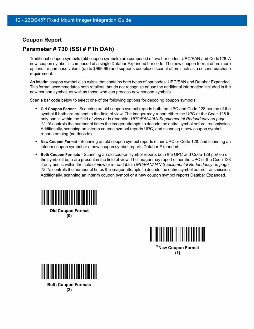
12 - 26DS457 Fixed Mount Imager Integration Guide
Coupon Report
Parameter # 730 (SSI # F1h DAh)Traditional coupon symbols (old coupon symbols) are composed of two bar codes: UPC/EAN and Code128. A new coupon symbol is composed of a single Databar Expanded bar code. The new coupon format offers more options for purchase values (up to $999.99) and supports complex discount offers such as a second purchase requirement.
An interim coupon symbol also exists that contains both types of bar codes: UPC/EAN and Databar Expanded. This format accommodates both retailers that do not recognize or use the additional information included in the new coupon symbol, as well as those who can process new coupon symbols.
Scan a bar code below to select one of the following options for decoding coupon symbols:
• Old Coupon Format - Scanning an old coupon symbol reports both the UPC and Code 128 portion of the symbol if both are present in the field of view. The imager may report either the UPC or the Code 128 if only one is within the field of view or is readable. UPC/EAN/JAN Supplemental Redundancy on page 12-15 controls the number of times the imager attempts to decode the entire symbol before transmission. Additionally, scanning an interim coupon symbol reports UPC, and scanning a new coupon symbol reports nothing (no decode).
• New Coupon Format - Scanning an old coupon symbol reports either UPC or Code 128, and scanning an interim coupon symbol or a new coupon symbol reports Databar Expanded.
• Both Coupon Formats - Scanning an old coupon symbol reports both the UPC and Code 128 portion of the symbol if both are present in the field of view. The imager may report either the UPC or the Code 128 if only one is within the field of view or is readable. UPC/EAN/JAN Supplemental Redundancy on page 12-15 controls the number of times the imager attempts to decode the entire symbol before transmission. Additionally, scanning an interim coupon symbol or a new coupon symbol reports Databar Expanded.
Old Coupon Format(0)
*New Coupon Format(1)
Both Coupon Formats(2)

Symbologies12 - 27
ISSN EAN
Parameter # 617 (SSI # F1h 69h)To enable or disable ISSN EAN, scan the appropriate bar code below.
Enable ISSN EAN (1)
*Disable ISSN EAN (0)

12 - 28DS457 Fixed Mount Imager Integration Guide
Code 128
Enable/Disable Code 128
Parameter # 8 (SSI # 08h)To enable or disable Code 128, scan the appropriate bar code below.
Set Lengths for Code 128
Parameter # L1 = 209 (SSI # D1h), L2 = 210 (SSI # D2h)
The length of a code refers to the number of characters (i.e., human readable characters), including check digit(s) the code contains. Set lengths for Code 128 to any length, one or two discrete lengths, or lengths within a specific range.
• One Discrete Length - Select this option to decode only Code 128 symbols containing a selected length. Select the length using the numeric bar codes in Appendix D, Numeric Bar Codes. For example, to decode only Code 128 symbols with 14 characters, scan Code 128 - One Discrete Length, then scan 1 followed by 4. To correct an error or change the selection, scan Cancel on page D-3.
• Two Discrete Lengths - Select this option to decode only Code 128 symbols containing either of two selected lengths. Select lengths using the numeric bar codes in Appendix D, Numeric Bar Codes. For example, to decode only those Code 128 symbols containing either 2 or 14 characters, select Code 128 - Two Discrete Lengths, then scan 0, 2, 1, and then 4. To correct an error or change the selection, scan Cancel on page D-3.
• Length Within Range - Select this option to decode a Code 128 symbol with a specific length range. Select lengths using numeric bar codes in Appendix D, Numeric Bar Codes. For example, to decode Code 128 symbols containing between 4 and 12 characters, first scan Code 128 - Length Within Range. Then scan 0, 4, 1, and 2 (single digit numbers must always be preceded by a leading zero). To correct an error or change the selection, scan Cancel on page D-3.
• Any Length - Select this option to decode Code 128 symbols containing any number of characters within the imager’s capability.
*Enable Code 128(1)
Disable Code 128(0)
NOTE When setting lengths for different bar code types by scanning single digit numbers, single digit numbers must always be preceded by a leading zero.

Symbologies12 - 29
Set Lengths for Code 128 (continued)
Code 128 - One Discrete Length
Code 128 - Two Discrete Lengths
Code 128 - Length Within Range
*Code 128 - Any Length
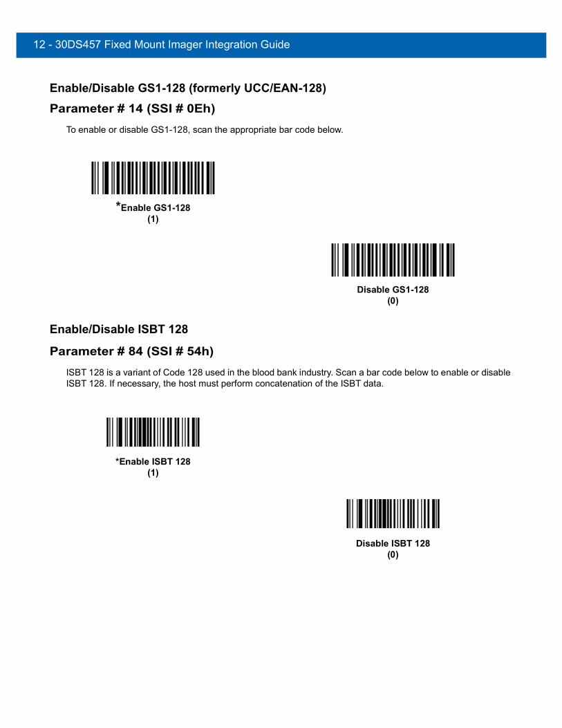
12 - 30DS457 Fixed Mount Imager Integration Guide
Enable/Disable GS1-128 (formerly UCC/EAN-128)
Parameter # 14 (SSI # 0Eh)To enable or disable GS1-128, scan the appropriate bar code below.
Enable/Disable ISBT 128
Parameter # 84 (SSI # 54h)ISBT 128 is a variant of Code 128 used in the blood bank industry. Scan a bar code below to enable or disable ISBT 128. If necessary, the host must perform concatenation of the ISBT data.
*Enable GS1-128(1)
Disable GS1-128(0)
*Enable ISBT 128(1)
Disable ISBT 128(0)

Symbologies12 - 31
ISBT Concatenation
Parameter # 577 (SSI # F1h 41h)Select an option for concatenating pairs of ISBT code types:
• If you select Disable ISBT Concatenation, the imager does not concatenate pairs of ISBT codes it encounters.
• If you select Enable ISBT Concatenation, there must be two ISBT codes in order for the imager to decode and perform concatenation. The imager does not decode single ISBT symbols.
• If you select Autodiscriminate ISBT Concatenation, the imager decodes and concatenates pairs of ISBT codes immediately. If only a single ISBT symbol is present, the imager must decode the symbol the number of times set via ISBT Concatenation Redundancy on page 12-32 before transmitting its data to confirm that there is no additional ISBT symbol.
*Disable ISBT Concatenation(0)
Enable ISBT Concatenation(1)
Autodiscriminate ISBT Concatenation(2)

12 - 32DS457 Fixed Mount Imager Integration Guide
Check ISBT Table
Parameter # 578 (SSI # F1h 42h)The ISBT specification includes a table that lists several types of ISBT bar codes that are commonly used in pairs. If you set ISBT Concatenation to Enable, enable Check ISBT Table to concatenate only those pairs found in this table. Other types of ISBT codes are not concatenated.
ISBT Concatenation Redundancy
Parameter # 223 (SSI # DFh)If you set ISBT Concatenation to Autodiscriminate, use this parameter to set the number of times the imager must decode an ISBT symbol before determining that there is no additional symbol.
Scan the bar code below, then scan two numeric bar codes in Appendix D, Numeric Bar Codes to set a value between 2 and 20. Enter a leading zero for single digit numbers. To correct an error or change a selection, scan Cancel on page D-3. The default is 10.
*Enable Check ISBT Table(1)
Disable Check ISBT Table(0)
ISBT Concatenation Redundancy
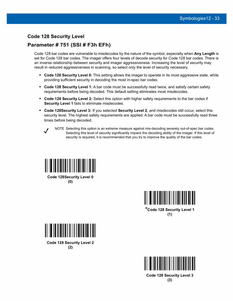
Symbologies12 - 33
Code 128 Security Level
Parameter # 751 (SSI # F3h EFh)Code 128 bar codes are vulnerable to misdecodes by the nature of the symbol, especially when Any Length is set for Code 128 bar codes. The imager offers four levels of decode security for Code 128 bar codes. There is an inverse relationship between security and imager aggressiveness. Increasing the level of security may result in reduced aggressiveness in scanning, so select only the level of security necessary.
• Code 128 Security Level 0: This setting allows the imager to operate in its most aggressive state, while providing sufficient security in decoding the most in-spec bar codes.
• Code 128 Security Level 1: A bar code must be successfully read twice, and satisfy certain safety requirements before being decoded. This default setting eliminates most misdecodes.
• Code 128 Security Level 2: Select this option with higher safety requirements to the bar codes if Security Level 1 fails to eliminate misdecodes.
• Code 128Security Level 3: If you selected Security Level 2, and misdecodes still occur, select this security level. The highest safety requirements are applied. A bar code must be successfully read three times before being decoded.
NOTE Selecting this option is an extreme measure against mis-decoding severely out-of-spec bar codes. Selecting this level of security significantly impairs the decoding ability of the imager. If this level of security is required, it is recommended that you try to improve the quality of the bar codes.
Code 128Security Level 0(0)
*Code 128 Security Level 1(1)
Code 128 Security Level 2(2)
Code 128 Security Level 3(3)
12 - 34DS457 Fixed Mount Imager Integration Guide
Code 39
Enable/Disable Code 39
Parameter # 0 (SSI # 00h)To enable or disable Code 39, scan the appropriate bar code below.
Enable/Disable Trioptic Code 39
Parameter # 13 (SSI # 0Dh)Trioptic Code 39 is a variant of Code 39 used in the marking of computer tape cartridges. Trioptic Code 39 symbols always contain six characters. To enable or disable Trioptic Code 39, scan the appropriate bar code below.
*Enable Code 39(1)
Disable Code 39(0)
Enable Trioptic Code 39(1)
*Disable Trioptic Code 39(0)
NOTE Trioptic Code 39 and Code 39 Full ASCII cannot be enabled simultaneously.

Symbologies12 - 35
Convert Code 39 to Code 32
Parameter # 86 (SSI # 56h)Code 32 is a variant of Code 39 used by the Italian pharmaceutical industry. Scan the appropriate bar code below to enable or disable converting Code 39 to Code 32.
Code 32 Prefix
Parameter # 231 (SSI # E7h)Scan the appropriate bar code below to enable or disable adding the prefix character “A” to all Code 32 bar codes.
NOTE Code 39 must be enabled for this parameter to function.
Enable Convert Code 39 to Code 32(1)
*Disable Convert Code 39 to Code 32(0)
NOTE Convert Code 39 to Code 32 must be enabled for this parameter to function.
Enable Code 32 Prefix(1)
*Disable Code 32 Prefix(0)

12 - 36DS457 Fixed Mount Imager Integration Guide
Set Lengths for Code 39
Parameter # L1 = 18 (SSI # 12h), L2 = 19 (SSI # 13h)The length of a code refers to the number of characters (i.e., human readable characters), including check digit(s) the code contains. Set lengths for Code 39 to any length, one or two discrete lengths, or lengths within a specific range. If Code 39 Full ASCII is enabled, Length Within a Range or Any Length are the preferred options.
• One Discrete Length - Select this option to decode only Code 39 symbols containing a selected length. Select the length using the numeric bar codes in Appendix D, Numeric Bar Codes. For example, to decode only Code 39 symbols with 14 characters, scan Code 39 - One Discrete Length, then scan 1 followed by 4. To correct an error or change the selection, scan Cancel on page D-3.
• Two Discrete Lengths - Select this option to decode only Code 39 symbols containing either of two selected lengths. Select lengths using the numeric bar codes in Appendix D, Numeric Bar Codes. For example, to decode only those Code 39 symbols containing either 2 or 14 characters, select Code 39 - Two Discrete Lengths, then scan 0, 2, 1, and then 4. To correct an error or change the selection, scan Cancel on page D-3.
• Length Within Range - Select this option to decode a Code 39 symbol with a specific length range. Select lengths using numeric bar codes in Appendix D, Numeric Bar Codes. For example, to decode Code 39 symbols containing between 4 and 12 characters, first scan Code 39 - Length Within Range. Then scan 0, 4, 1, and 2 (single digit numbers must always be preceded by a leading zero). To correct an error or change the selection, scan Cancel on page D-3.
• Any Length - Select this option to decode Code 39 symbols containing any number of characters within the imager’s capability.
NOTE When setting lengths for different bar code types by scanning single digit numbers, single digit numbers must always be preceded by a leading zero.
Code 39 - One Discrete Length
Code 39 - Two Discrete Lengths

Symbologies12 - 37
Set Lengths for Code 39 (continued)
Code 39 Check Digit Verification
Parameter # 48 (SSI # 30h)When this feature is enabled, the imager checks the integrity of all Code 39 symbols to verify that the data complies with specified check digit algorithm. Only Code 39 symbols which include a modulo 43 check digit are decoded. Enable this feature if the Code 39 symbols contain a Modulo 43 check digit.
Code 39 - Length Within Range
Code 39 - Any Length
Enable Code 39 Check Digit(1)
*Disable Code 39 Check Digit (0)

12 - 38DS457 Fixed Mount Imager Integration Guide
Transmit Code 39 Check Digit
Parameter # 43 (SSI # 2Bh)Scan a bar code below to transmit Code 39 data with or without the check digit.
Code 39 Full ASCII Conversion
Parameter # 17 (SSI # 11h)Code 39 Full ASCII is a variant of Code 39 which pairs characters to encode the full ASCII character set. To enable or disable Code 39 Full ASCII, scan the appropriate bar code below.
Transmit Code 39 Check Digit (Enable)(1)
*Do Not Transmit Code 39 Check Digit (Disable)(0)
NOTE Code 39 Check Digit Verification must be enabled for this parameter to function.
Enable Code 39 Full ASCII(1)
*Disable Code 39 Full ASCII(0)
NOTE Trioptic Code 39 and Code 39 Full ASCII cannot be enabled simultaneously.
Code 39 Full ASCII to Full ASCII Correlation is host-dependent, and is therefore described in the ASCII Character Set Table for the appropriate interface. See Appendix E, ASCII Character Set.
Symbologies12 - 39
Code 39 Buffering (Scan & Store)
Parameter # 113 (SSI # 71h)This feature allows the imager to accumulate data from multiple Code 39 symbols.
Selecting the Scan and Store option (Buffer Code 39) temporarily buffers all Code 39 symbols having a leading space as a first character for later transmission. The leading space is not buffered.
Decode of a valid Code 39 symbol with no leading space causes transmission in sequence of all buffered data in a first-in first-out format, plus transmission of the “triggering” symbol. See the following pages for further details.
When the Do Not Buffer Code 39 option is selected, all decoded Code 39 symbols are transmitted immediately without being stored in the buffer.
This feature affects Code 39 only. If selecting Buffer Code 39, we recommend configuring the imager to decode Code 39 symbology only.
While there is data in the transmission buffer, selecting Do Not Buffer Code 39 is not allowed. The buffer holds 128 bytes of information.
To disable Code 39 buffering when there is data in the transmission buffer, first force the buffer transmission (see Transmit Buffer on page 12-40) or clear the buffer.
Buffer DataTo buffer data, Code 39 buffering must be enabled and a Code 39 symbol must be read with a space immediately following the start pattern.
• Unless the data overflows the transmission buffer, the imager issues a lo/hi beep to indicate successful decode and buffering. (For overflow conditions, see Overfilling Transmission Buffer.)
• The imager adds the decoded data excluding the leading space to the transmission buffer.
• No transmission occurs.
Buffer Code 39 (Enable)(1)
*Do Not Buffer Code 39 (Disable)(0)

12 - 40DS457 Fixed Mount Imager Integration Guide
Clear Transmission BufferTo clear the transmission buffer, scan the Clear Buffer bar code below, which contains only a start character, a dash (minus), and a stop character.
• The imager issues a short hi/lo/hi beep.
• The imager erases the transmission buffer.
• No transmission occurs.
Transmit BufferThere are two methods to transmit the Code 39 buffer.
1. Scan the Transmit Buffer bar code below. Only a start character, a plus (+), and a stop character.
• The imager transmits and clears the buffer.
• The imager issues a Lo/Hi beep.
2. Scan a Code 39 bar code with a leading character other than a space.• The imager appends new decode data to buffered data.• The imager transmits and clears the buffer.• The imager signals that the buffer was transmitted with a lo/hi beep.• The imager transmits and clears the buffer.
Clear Buffer
NOTE The Clear Buffer contains only the dash (minus) character. In order to scan this command, be sure Code 39 length is set to include length 1.
Transmit Buffer
NOTE The Transmit Buffer contains only a plus (+) character. In order to scan this command, be sure Code 39 length is set to include length 1.

Symbologies12 - 41
Overfilling Transmission BufferThe Code 39 buffer holds 128 characters. If the symbol just read results in an overflow of the transmission buffer:
• The imager indicates that the symbol was rejected by issuing three long, high beeps.
• No transmission occurs. The data in the buffer is not affected.
Attempt to Transmit an Empty BufferIf the symbol just read was the Transmit Buffer symbol and the Code 39 buffer is empty:
• A short lo/hi/lo beep signals that the buffer is empty.
• No transmission occurs.
• The buffer remains empty.

12 - 42DS457 Fixed Mount Imager Integration Guide
Code 39 Security Level
Parameter # 750 (SSI # F3h EEh)The imager offers four levels of decode security for Code 39. Select increasing levels of security for decreasing levels of bar code quality. There is an inverse relationship between security and imager aggressiveness, so choose only that level of security necessary for any given application.
• Code 39 Security Level 0: This setting allows the imager to operate in its most aggressive state, while providing sufficient security in decoding most “in-spec” bar codes.
• Code 39 Security Level 1: This default setting eliminates most misdecodes.
• Code 39 Security Level 2: Select this option if Security level 1 fails to eliminate misdecodes.
• Code 39 Security Level 3: If you selected Security Level 2 and misdecodes still occur, select this security level. Be advised, selecting this option is an extreme measure against mis-decoding severely out of spec bar codes. Selecting this level of security significantly impairs the decoding ability of the imager. If you need this level of security, try to improve the quality of the bar codes.
Code 39 Security Level 0(0)
*Code 39 Security Level 1(1)
Code 39 Security Level 2(2)
Code 39 Security Level 3(3)

Symbologies12 - 43
Code 93
Enable/Disable Code 93
Parameter # 9 (SSI # 09h)To enable or disable Code 93, scan the appropriate bar code below.
Set Lengths for Code 93
Parameter # L1 = 26 (SSI # 1Ah), L2 = 27 (SSI # 1Bh)The length of a code refers to the number of characters (i.e., human readable characters), including check digit(s) the code contains. Set lengths for Code 93 to any length, one or two discrete lengths, or lengths within a specific range.
• One Discrete Length - Select this option to decode only Code 93 symbols containing a selected length. Select the length using the numeric bar codes in Appendix D, Numeric Bar Codes. For example, to decode only Code 93 symbols with 14 characters, scan Code 93 - One Discrete Length, then scan 1 followed by 4. To correct an error or to change the selection, scan Cancel on page D-3.
• Two Discrete Lengths - Select this option to decode only Code 93 symbols containing either of two selected lengths. Select lengths using the numeric bar codes in Appendix D, Numeric Bar Codes. For example, to decode only those Code 93 symbols containing either 2 or 14 characters, select Code 93 - Two Discrete Lengths, then scan 0, 2, 1, and then 4. To correct an error or to change the selection, scan Cancel on page D-3.
• Length Within Range - Select this option to decode a Code 93 symbol with a specific length range. Select lengths using the numeric bar codes in Appendix D, Numeric Bar Codes. For example, to decode Code 93 symbols containing between 4 and 12 characters, first scan Code 93 - Length Within Range. Then scan 0, 4, 1, and 2 (single digit numbers must always be preceded by a leading zero). To correct an error or change the selection, scan Cancel on page D-3.
• Any Length - Scan this option to decode Code 93 symbols containing any number of characters within the imager’s capability.
Enable Code 93(1)
*Disable Code 93(0)

12 - 44DS457 Fixed Mount Imager Integration Guide
Set Lengths for Code 93 (continued)
Code 93 - One Discrete Length
Code 93 - Two Discrete Lengths
Code 93 - Length Within Range
Code 93 - Any Length
Symbologies12 - 45
Code 11
Code 11
Parameter # 10 (SSI # 0Ah)To enable or disable Code 11, scan the appropriate bar code below.
Set Lengths for Code 11
Parameter # L1 = 28 (SSI # 1Ch), L2 = 29 (SSI # 1Dh)The length of a code refers to the number of characters (i.e., human readable characters), including check digit(s) the code contains. Set lengths for Code 11 to any length, one or two discrete lengths, or lengths within a specific range.
• One Discrete Length - Select this option to decode only Code 11 symbols containing a selected length. Select the length using the numeric bar codes in Appendix D, Numeric Bar Codes. For example, to decode only Code 11 symbols with 14 characters, scan Code 11 - One Discrete Length, then scan 1 followed by 4. To correct an error or to change the selection, scan Cancel on page D-3.
• Two Discrete Lengths - Select this option to decode only Code 11 symbols containing either of two selected lengths. Select lengths using the numeric bar codes in Appendix D, Numeric Bar Codes. For example, to decode only those Code 11 symbols containing either 2 or 14 characters, select Code 11 - Two Discrete Lengths, then scan 0, 2, 1, and then 4. To correct an error or to change the selection, scan Cancel on page D-3.
• Length Within Range - Select this option to decode a Code 11 symbol with a specific length range. Select lengths using numeric bar codes in Appendix D, Numeric Bar Codes. For example, to decode Code 11 symbols containing between 4 and 12 characters, first scan Code 11 - Length Within Range. Then scan 0, 4, 1, and 2 (single digit numbers must always be preceded by a leading zero). To correct an error or change the selection, scan Cancel on page D-3.
• Any Length - Scan this option to decode Code 11 symbols containing any number of characters within the imager’s capability.
Enable Code 11(1)
*Disable Code 11(0)

12 - 46DS457 Fixed Mount Imager Integration Guide
Set Lengths for Code 11 (continued)
Code 11 - One Discrete Length
Code 11 - Two Discrete Lengths
Code 11 - Length Within Range
Code 11 - Any Length

Symbologies12 - 47
Code 11 Check Digit Verification
Parameter # 52 (SSI # 34h)This feature allows the imager to check the integrity of all Code 11 symbols to verify that the data complies with the specified check digit algorithm. This selects the check digit mechanism for the decoded Code 11 bar code. The options are to check for one check digit, check for two check digits, or disable the feature.
To enable this feature, scan the bar code below corresponding to the number of check digits encoded in the Code 11 symbols.
*Disable(0)
One Check Digit(1)
Two Check Digits(2)
12 - 48DS457 Fixed Mount Imager Integration Guide
Transmit Code 11 Check Digits
Parameter # 47 (SSI # 2Fh)This feature selects whether or not to transmit the Code 11 check digit(s).
Interleaved 2 of 5 (ITF)
Enable/Disable Interleaved 2 of 5
Parameter # 6 (SSI # 06h)To enable or disable Interleaved 2 of 5, scan the appropriate bar code below, and select an Interleaved 2 of 5 length from the following pages.
Transmit Code 11 Check Digit(s) (Enable)(1)
*Do Not Transmit Code 11 Check Digit(s) (Disable)(0)
NOTE Code 11 Check Digit Verification must be enabled for this parameter to function.
*Enable Interleaved 2 of 5(1)
Disable Interleaved 2 of 5(0)
Symbologies12 - 49
Set Lengths for Interleaved 2 of 5
Parameter # L1 = 22 (SSI # 16h), L2 = 23 (SSI # 17h)The length of a code refers to the number of characters (i.e., human readable characters), including check digit(s) the code contains. Set lengths for I 2 of 5 to any length, one or two discrete lengths, or lengths within a specific range.
• One Discrete Length - Select this option to decode only I 2 of 5 symbols containing a selected length. Select the length using the numeric bar codes in Appendix D, Numeric Bar Codes. For example, to decode only I 2 of 5 symbols with 14 characters, scan I 2 of 5 - One Discrete Length, then scan 1 followed by 4. To correct an error or to change the selection, scan Cancel on page D-3.
• Two Discrete Lengths - Select this option to decode only I 2 of 5 symbols containing either of two selected lengths. Select lengths using the numeric bar codes in Appendix D, Numeric Bar Codes. For example, to decode only those I 2 of 5 symbols containing either 2 or 14 characters, select I 2 of 5 - Two Discrete Lengths, then scan 0, 2, 1, and then 4. To correct an error or to change the selection, scan Cancel on page D-3.
• Length Within Range - Select this option to decode an I 2 of 5 symbol with a specific length range. Select lengths using numeric bar codes in Appendix D, Numeric Bar Codes. For example, to decode I 2 of 5 symbols containing between 4 and 12 characters, first scan I 2 of 5 - Length Within Range. Then scan 0, 4, 1, and 2 (single digit numbers must always be preceded by a leading zero). To correct an error or change the selection, scan Cancel on page D-3.
• Any Length - Scan this option to decode I 2 of 5 symbols containing any number of characters within the imager’s capability.
NOTE Due to the construction of the I 2 of 5 symbology, it is possible for a scan line covering only a portion of the code to be interpreted as a complete scan, yielding less data than is encoded in the bar code. To prevent this, select specific lengths (I 2 of 5 - One Discrete Length - Two Discrete Lengths) for I 2 of 5 applications.
I 2 of 5 - One Discrete Length
I 2 of 5 - Two Discrete Lengths

12 - 50DS457 Fixed Mount Imager Integration Guide
Set Lengths for Interleaved 2 of 5 (continued)
I 2 of 5 Check Digit Verification
Parameter # 49 (SSI # 31h)When this feature is enabled, the imager checks the integrity of all I 2 of 5 symbols to verify the data complies with either the specified Uniform Symbology Specification (USS), or the Optical Product Code Council (OPCC) check digit algorithm.
I 2 of 5 - Length Within Range
I 2 of 5 - Any Length
*Disable(0)
USS Check Digit (1)
OPCC Check Digit (2)

Symbologies12 - 51
Transmit I 2 of 5 Check Digit
Parameter # 44 (SSI # 2Ch)Scan the appropriate bar code below to transmit I 2 of 5 data with or without the check digit.
Convert I 2 of 5 to EAN-13
Parameter # 82 (SSI # 52h)Enable this parameter to convert 14-character I 2 of 5 codes to EAN-13, and transmit to the host as EAN-13. To accomplish this, the I 2 of 5 code must be enabled, and the code must have a leading zero and a valid EAN-13 check digit.
Transmit I 2 of 5 Check Digit (Enable)(1)
*Do Not Transmit I 2 of 5 Check Digit (Disable)(0)
Convert I 2 of 5 to EAN-13 (Enable)(1)
*Do Not Convert I 2 of 5 to EAN-13 (Disable)(0)

12 - 52DS457 Fixed Mount Imager Integration Guide
I 2 of 5 Security Level
Parameter # 1121Interleaved 2 of 5 bar codes are vulnerable to misdecodes, particularly when I 2 of 5 Lengths is set to Any Length. The imager offers four levels of decode security for Interleaved 2 of 5 bar codes. There is an inverse relationship between security and imager aggressiveness. Increasing the level of security can reduce scanning aggressiveness, so select only the level of security necessary.
• I 2 of 5 Security Level 0: This setting allows the imager to operate in its most aggressive state, while providing sufficient security in decoding most in-spec bar codes.
• I 2 of 5 Security Level 1: A bar code must be successfully read twice, and satisfy certain safety requirements before being decoded. This default setting eliminates most misdecodes.
• I 2 of 5 Security Level 2: Select this option with greater bar code security requirements if Security Level 1 fails to eliminate misdecodes.
• I 2 of 5 Security Level 3: If you selected Security Level 2, and misdecodes still occur, select this security level. The highest safety requirements are applied. A bar code must be successfully read three times before being decoded.
NOTE Selecting this option is an extreme measure against mis-decoding severely out-of-spec bar codes. Selecting this level of security significantly impairs the decoding ability of the imager. If this level of security is required, try to improve the quality of the bar codes.
I 2 of 5 Security Level 0(0)
*I 2 of 5 Security Level 1(1)
I 2 of 5 Security Level 2(2)
I 2 of 5 Security Level 3(3)

Symbologies12 - 53
Discrete 2 of 5 (DTF)
Enable/Disable Discrete 2 of 5
Parameter # 5 (SSI # 05h)To enable or disable Discrete 2 of 5, scan the appropriate bar code below.
Set Lengths for Discrete 2 of 5
Parameter # L1 = 20 (SSI # 14h), L2 = 21 (SSI # 15h)The length of a code refers to the number of characters (i.e., human readable characters), including check digit(s) the code contains. Set lengths for D 2 of 5 to any length, one or two discrete lengths, or lengths within a specific range.
• One Discrete Length - Select this option to decode only D 2 of 5 symbols containing a selected length. Select the length using the numeric bar codes in Appendix D, Numeric Bar Codes. For example, to decode only D 2 of 5 symbols with 14 characters, scan D 2 of 5 - One Discrete Length, then scan 1 followed by 4. To correct an error or to change the selection, scan Cancel on page D-3.
• Two Discrete Lengths - Select this option to decode only D 2 of 5 symbols containing either of two selected lengths. Select lengths using the numeric bar codes in Appendix D, Numeric Bar Codes. For example, to decode only those D 2 of 5 symbols containing either 2 or 14 characters, select D 2 of 5 - Two Discrete Lengths, then scan 0, 2, 1, and then 4. To correct an error or to change the selection, scan Cancel on page D-3.
• Length Within Range - Select this option to decode a D 2 of 5 symbol with a specific length range. Select lengths using numeric bar codes in Appendix D, Numeric Bar Codes. For example, to decode D 2 of 5 symbols containing between 4 and 12 characters, first scan D 2 of 5 - Length Within Range. Then scan 0, 4, 1, and 2 (single digit numbers must always be preceded by a leading zero). To correct an error or change the selection, scan Cancel on page D-3.
• Any Length - Scan this option to decode D 2 of 5 symbols containing any number of characters within the imager’s capability.
Enable Discrete 2 of 5(1)
*Disable Discrete 2 of 5(0)

12 - 54DS457 Fixed Mount Imager Integration Guide
Set Lengths for Discrete 2 of 5 (continued)
NOTE Due to the construction of the D 2 of 5 symbology, it is possible for a scan line covering only a portion of the code to be interpreted as a complete scan, yielding less data than is encoded in the bar code. To prevent this, select specific lengths (D 2 of 5 - One Discrete Length - Two Discrete Lengths) for D 2 of 5 applications.
D 2 of 5 - One Discrete Length
D 2 of 5 - Two Discrete Lengths
D 2 of 5 - Length Within Range
D 2 of 5 - Any Length

Symbologies12 - 55
Codabar (NW - 7)
Enable/Disable Codabar
Parameter # 7 (SSI # 07h)To enable or disable Codabar, scan the appropriate bar code below.
Set Lengths for Codabar
Parameter # L1 = 24 (SSI # 18h), L2 = 25 (SSI # 19h)The length of a code refers to the number of characters (i.e., human readable characters), including check digit(s) the code contains. Set lengths for Codabar to any length, one or two discrete lengths, or lengths within a specific range.
• One Discrete Length - Select this option to decode only Codabar symbols containing a selected length. Select the length using the numeric bar codes in Appendix D, Numeric Bar Codes. For example, to decode only Codabar symbols with 14 characters, scan Codabar - One Discrete Length, then scan 1 followed by 4. To correct an error or to change the selection, scan Cancel on page D-3.
• Two Discrete Lengths - Select this option to decode only Codabar symbols containing either of two selected lengths. Select lengths using the numeric bar codes in Appendix D, Numeric Bar Codes. For example, to decode only Codabar symbols containing either 2 or 14 characters, select Codabar - Two Discrete Lengths, then scan 0, 2, 1, and then 4. To correct an error or to change the selection, scan Cancel on page D-3.
• Length Within Range - Select this option to decode a Codabar symbol with a specific length range. Select lengths using numeric bar codes in Appendix D, Numeric Bar Codes. For example, to decode Codabar symbols containing between 4 and 12 characters, first scan Codabar - Length Within Range. Then scan 0, 4, 1, and 2 (single digit numbers must always be preceded by a leading zero). To correct an error or change the selection, scan Cancel on page D-3.
• Any Length - Scan this option to decode Codabar symbols containing any number of characters within the imager’s capability.
Enable Codabar(1)
*Disable Codabar(0)

12 - 56DS457 Fixed Mount Imager Integration Guide
Set Lengths for Codabar (continued)
Codabar - One Discrete Length
Codabar - Two Discrete Lengths
Codabar - Length Within Range
Codabar - Any Length
Symbologies12 - 57
CLSI Editing
Parameter # 54 (SSI # 36h)When enabled, this parameter strips the start and stop characters and inserts a space after the first, fifth, and tenth characters of a 14-character Codabar symbol. Enable this feature if the host system requires this data format.
NOTIS Editing
Parameter # 55 (SSI # 37h)When enabled, this parameter strips the start and stop characters from a decoded Codabar symbol. Enable this feature if the host system requires this data format.
NOTE Symbol length does not include start and stop characters.
Enable CLSI Editing(1)
*Disable CLSI Editing(0)
Enable NOTIS Editing(1)
*Disable NOTIS Editing(0)

12 - 58DS457 Fixed Mount Imager Integration Guide
Codabar Upper or Lower Case Start/Stop Characters Transmission
Parameter # 855 (SSI # F2h 57h)
Select whether to transmit upper case or lower case Codabar start/stop characters.
*Upper Case(0)
Lower Case(1)

Symbologies12 - 59
MSI
Enable/Disable MSI
Parameter # 11 (SSI # 0Bh)To enable or disable MSI, scan the appropriate bar code below.
Set Lengths for MSI
Parameter # L1 = 30 (SSI # 1Eh), L2 = 31 (SSI # 1Fh)The length of a code refers to the number of characters (i.e., human readable characters), including check digit(s) the code contains. Set lengths for MSI to any length, one or two discrete lengths, or lengths within a specific range.
• One Discrete Length - Select this option to decode only MSI symbols containing a selected length. Select the length using the numeric bar codes in Appendix D, Numeric Bar Codes. For example, to decode only MSI symbols with 14 characters, scan MSI - One Discrete Length, then scan 1 followed by 4. To correct an error or to change the selection, scan Cancel on page D-3.
• Two Discrete Lengths - Select this option to decode only MSI symbols containing either of two selected lengths. Select lengths using the numeric bar codes in Appendix D, Numeric Bar Codes. For example, to decode only MSI symbols containing either 2 or 14 characters, select MSI - Two Discrete Lengths, then scan 0, 2, 1, and then 4. To correct an error or to change the selection, scan Cancel on page D-3.
• Length Within Range - Select this option to decode a MSI symbol with a specific length range. Select lengths using numeric bar codes in Appendix D, Numeric Bar Codes. For example, to decode MSI symbols containing between 4 and 12 characters, first scan MSI - Length Within Range. Then scan 0, 4, 1, and 2 (single digit numbers must always be preceded by a leading zero). To correct an error or change the selection, scan Cancel on page D-3.
• Any Length - Scan this option to decode MSI symbols containing any number of characters within the imager’s capability.
Enable MSI(1)
*Disable MSI(0)

12 - 60DS457 Fixed Mount Imager Integration Guide
Set Lengths for MSI (continued)
NOTE Due to the construction of the MSI symbology, it is possible for a scan line covering only a portion of the code to be interpreted as a complete scan, yielding less data than is encoded in the bar code. To prevent this, select specific lengths (MSI - One Discrete Length - Two Discrete Lengths) for MSI applications.
MSI - One Discrete Length
MSI - Two Discrete Lengths
MSI - Length Within Range
MSI - Any Length
Symbologies12 - 61
MSI Check Digits
Parameter # 50 (SSI # 32h)With MSI symbols, one check digit is mandatory and always verified by the reader. The second check digit is optional. If the MSI codes include two check digits, scan the Two MSI Check Digits bar code to enable verification of the second check digit.
See MSI Check Digit Algorithm on page 12-62 for the selection of second digit algorithms.
*One MSI Check Digit(0)
Two MSI Check Digits(1)

12 - 62DS457 Fixed Mount Imager Integration Guide
Transmit MSI Check Digit(s)
Parameter # 46 (SSI # 2Eh)Scan a bar code below to transmit MSI data with or without the check digit.
MSI Check Digit Algorithm
Parameter # 51 (SSI # 33h)Two algorithms are possible for the verification of the second MSI check digit. Select the bar code below corresponding to the algorithm used to encode the check digit.
Transmit MSI Check Digit(s) (Enable)(1)
*Do Not Transmit MSI Check Digit(s) (Disable)(0)
MOD 11/MOD 10(0)
*MOD 10/MOD 10(1)

Symbologies12 - 63
Chinese 2 of 5
Enable/Disable Chinese 2 of 5
Parameter # 408 (SSI # F0h 98h)To enable or disable Chinese 2 of 5, scan the appropriate bar code below.
Matrix 2 of 5
Enable/Disable Matrix 2 of 5
Parameter # 618 (SSI # F1h 6Ah)To enable or disable Matrix 2 of 5, scan the appropriate bar code below.
Enable Chinese 2 of 5(1)
*Disable Chinese 2 of 5(0)
Enable Matrix 2 of 5 (1)
*Disable Matrix 2 of 5 (0)

12 - 64DS457 Fixed Mount Imager Integration Guide
Set Lengths for Matrix 2 of 5
Parameter # L1 = 619 (SSI # F1h 6Bh), L2 = 620 (SSI # F1h 6Ch)The length of a code refers to the number of characters (i.e., human readable characters), including check digit(s) the code contains. Set lengths for Matrix 2 of 5 to any length, one or two discrete lengths, or lengths within a specific range.
• One Discrete Length - Select this option to decode only Matrix 2 of 5 symbols containing a selected length. Select the length using the numeric bar codes in Appendix D, Numeric Bar Codes. For example, to decode only Matrix 2 of 5 symbols with 14 characters, scan Matrix 2 of 5 - One Discrete Length, then scan 1 followed by 4. To correct an error or to change the selection, scan Cancel on page D-3.
• Two Discrete Lengths - Select this option to decode only Matrix 2 of 5 symbols containing either of two selected lengths. Select lengths using the numeric bar codes in Appendix D, Numeric Bar Codes. For example, to decode only Matrix 2 of 5 symbols containing either 2 or 14 characters, select Matrix 2 of 5 - Two Discrete Lengths, then scan 0, 2, 1, and then 4. To correct an error or to change the selection, scan Cancel on page D-3.
• Length Within Range - Select this option to decode a Matrix 2 of 5 symbol with a specific length range. Select lengths using the numeric bar codes in Appendix D, Numeric Bar Codes. For example, to decode Matrix 2 of 5 symbols containing between 4 and 12 characters, first scan Matrix 2 of 5 - Length Within Range. Then scan 0, 4, 1, and 2 (enter a leading zero for single digit numbers). To correct an error or change the selection, scan Cancel on page D-3.
• Any Length - Scan this option to decode Matrix 2 of 5 symbols containing any number of characters within the imager’s capability.
*Matrix 2 of 5 - One Discrete Length
Matrix 2 of 5 - Two Discrete Lengths
Matrix 2 of 5 - Length Within Range
Matrix 2 of 5 - Any Length

Symbologies12 - 65
Matrix 2 of 5 Check Digit
Parameter # 622 (SSI # F1h 6Eh)The check digit is the last character of the symbol used to verify the integrity of the data. Scan the appropriate bar code below to transmit the bar code data with or without the Matrix 2 of 5 check digit.
Transmit Matrix 2 of 5 Check Digit
Parameter # 623 (SSI # F1h 6Fh)Scan a bar code below to transmit Matrix 2 of 5 data with or without the check digit.
Enable Matrix 2 of 5 Check Digit(1)
*Disable Matrix 2 of 5 Check Digit(0)
Transmit Matrix 2 of 5 Check Digit(1)
*Do Not Transmit Matrix 2 of 5 Check Digit(0)

12 - 66DS457 Fixed Mount Imager Integration Guide
Korean 3 of 5
Enable/Disable Korean 3 of 5
Parameter # 581 (SSI # F1h 45h)To enable or disable Korean 3 of 5, scan the appropriate bar code below.
NOTE The length for Korean 3 of 5 is fixed at 6.
Enable Korean 3 of 5 (1)
*Disable Korean 3 of 5 (0)

Symbologies12 - 67
Inverse 1D
Parameter # 586 (SSI # F1h 4Ah)
This parameter sets the 1D inverse imager setting. Options are:
• Regular Only - the imager decodes regular 1D bar codes only.
• Inverse Only - the imager decodes inverse 1D bar codes only.
• Inverse Autodetect - the imager decodes both regular and inverse 1D bar codes.
*Regular(0)
Inverse Only(1)
Inverse Autodetect(2)
(Default for DS457-DP Only)

12 - 68DS457 Fixed Mount Imager Integration Guide
Postal Codes
US Postnet
Parameter # 89 (SSI # 59h)To enable or disable US Postnet, scan the appropriate bar code below.
US Planet
Parameter # 90 (SSI # 5Ah)To enable or disable US Planet, scan the appropriate bar code below.
Enable US Postnet(1)
*Disable US Postnet(0)
Enable US Planet(1)
*Disable US Planet(0)
Symbologies12 - 69
Transmit US Postal Check Digit
Parameter # 95 (SSI # 5Fh)Select whether to transmit US Postal data, which includes both US Postnet and US Planet, with or without the check digit.
UK Postal
Parameter # 91 (SSI # 5Bh)To enable or disable UK Postal, scan the appropriate bar code below.
*Transmit US Postal Check Digit(1)
Do Not Transmit US Postal Check Digit(0)
Enable UK Postal(1)
*Disable UK Postal(0)
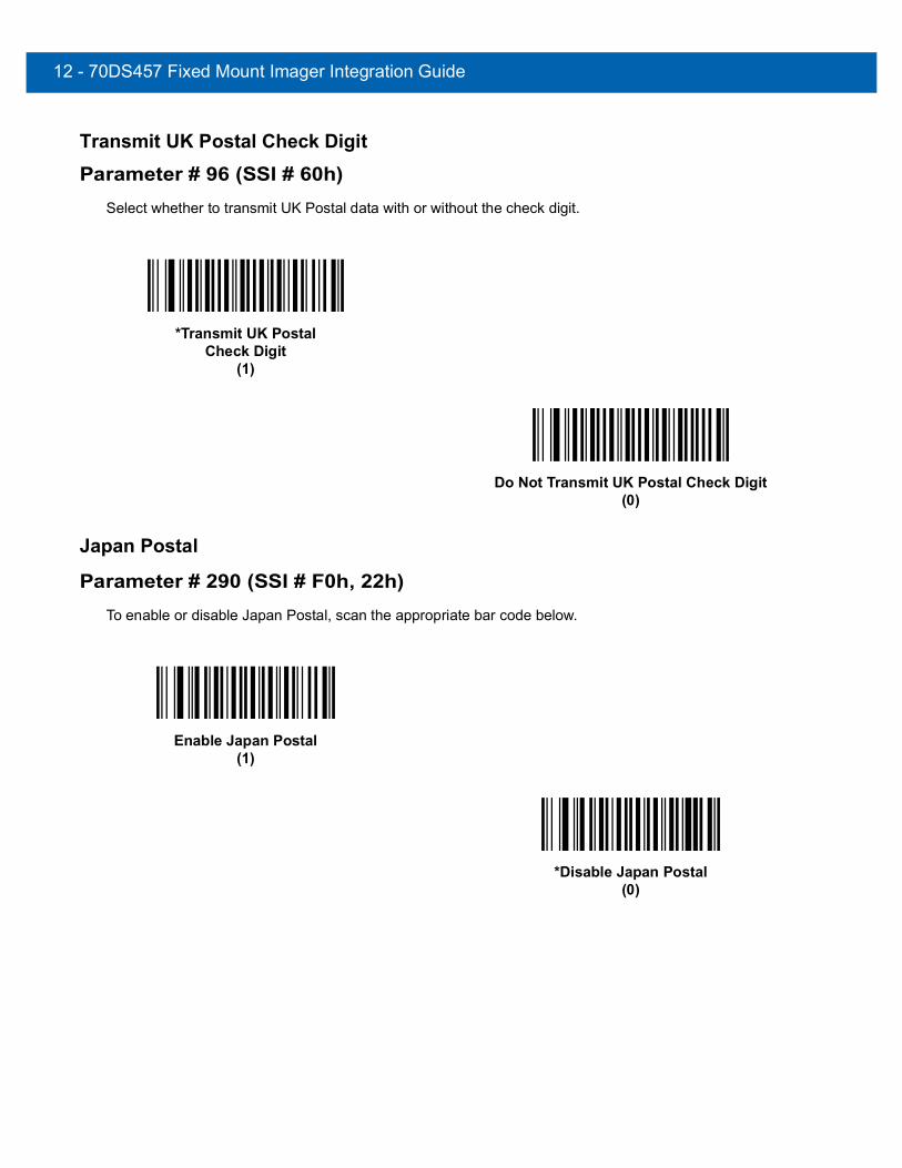
12 - 70DS457 Fixed Mount Imager Integration Guide
Transmit UK Postal Check Digit
Parameter # 96 (SSI # 60h)Select whether to transmit UK Postal data with or without the check digit.
Japan Postal
Parameter # 290 (SSI # F0h, 22h)To enable or disable Japan Postal, scan the appropriate bar code below.
*Transmit UK PostalCheck Digit
(1)
Do Not Transmit UK Postal Check Digit(0)
Enable Japan Postal(1)
*Disable Japan Postal(0)
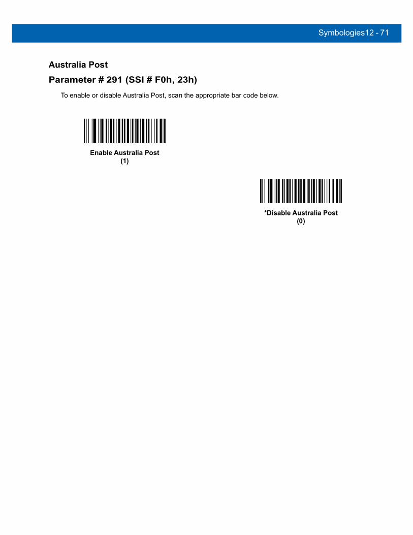
Symbologies12 - 71
Australia Post
Parameter # 291 (SSI # F0h, 23h)To enable or disable Australia Post, scan the appropriate bar code below.
Enable Australia Post(1)
*Disable Australia Post(0)

12 - 72DS457 Fixed Mount Imager Integration Guide
Australia Post Format
Parameter # 718 (SSI # F1h, CEh)To select one of the following formats for Australia Post, scan the appropriate bar code below:
• Autodiscriminate (or Smart mode) - Attempt to decode the Customer Information Field using the N and C Encoding Tables.
• Raw Format - Output raw bar patterns as a series of numbers 0 through 3.
• Alphanumeric Encoding - Decode the Customer Information Field using the C Encoding Table.
• Numeric Encoding - Decode the Customer Information Field using the N Encoding Table.
For more information on Australia Post Encoding Tables, refer to the Australia Post Customer Barcoding Technical Specifications available at http://www.auspost.com.au.
NOTE This option increases the risk of misdecodes because the encoded data format does not specify the Encoding Table used for encoding.
*Autodiscriminate(0)
Raw Format(1)
Alphanumeric Encoding(2)
Numeric Encoding(3)

Symbologies12 - 73
Netherlands KIX Code
Parameter # 326 (SSI # F0h, 46h)To enable or disable Netherlands KIX Code, scan the appropriate bar code below.
Enable Netherlands KIX Code(1)
*Disable Netherlands KIX Code(0)
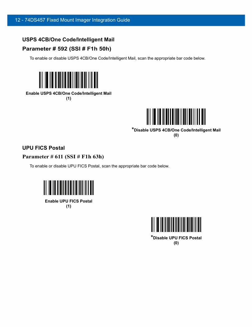
12 - 74DS457 Fixed Mount Imager Integration Guide
USPS 4CB/One Code/Intelligent Mail
Parameter # 592 (SSI # F1h 50h)To enable or disable USPS 4CB/One Code/Intelligent Mail, scan the appropriate bar code below.
UPU FICS PostalParameter # 611 (SSI # F1h 63h)
To enable or disable UPU FICS Postal, scan the appropriate bar code below.
Enable USPS 4CB/One Code/Intelligent Mail (1)
*Disable USPS 4CB/One Code/Intelligent Mail (0)
Enable UPU FICS Postal(1)
*Disable UPU FICS Postal (0)

Symbologies12 - 75
GS1 DataBar (formerly RSS, Reduced Space Symbology)GS1 DataBar types are:
• GS1 DataBar Omnidirectional
• GS1 DataBar Truncated
• GS1 DataBar Stacked
• GS1 DataBar Stacked Omnidirectional
• GS1 DataBar Limited
• GS1 DataBar Expanded
• GS1 DataBar Expanded Stacked
Scan the appropriate bar codes to enable or disable each type of GS1 DataBar.
GS1 DataBar
Parameter # 338 (SSI # F0h 52h)Scan the appropriate bar code below to enable or disable the following code types:
• GS1 DataBar Omnidirectional
• GS1 DataBar Truncated
• GS1 DataBar Stacked
• GS1 DataBar Stacked Omnidirectional
*Enable GS1 DataBar(1)
Disable GS1 DataBar(0)

12 - 76DS457 Fixed Mount Imager Integration Guide
GS1 DataBar Limited
Parameter # 339 (SSI # F0h 53h)
*Enable GS1 DataBar Limited(1)
Disable GS1 DataBar Limited(0)

Symbologies12 - 77
GS1 DataBar Limited Security Level
Parameter # 728 (SSI # F1h D8h)
The imager offers four levels of decode security for GS1 DataBar Limited bar codes. There is an inverse relationship between security and decoder aggressiveness. Increasing the level of security can reduce aggressiveness in scanning, so only choose the level of security necessary.
• Level 1 – No clear margin required. This complies with the original GS1 standard, yet might result in erroneous decoding of the DataBar Limited bar code when scanning some UPC symbols that start with the digits “9” and “7”.
• Level 2 – Automatic risk detection. This level of security may result in erroneous decoding of DataBar Limited bar codes when scanning some UPC symbols. If a misdecode is detected, the decoder operates in Level 3 or Level 1.
• Level 3 – Security level reflects newly proposed GS1 standard that requires a 5X trailing clear margin.
• Level 4 – Security level extends beyond the standard required by GS1. This level of security requires a 5X leading and trailing clear margin.
Security Level 1(1)
Security Level 2(2)
*Security Level 3(3)
Security Level 4(4)
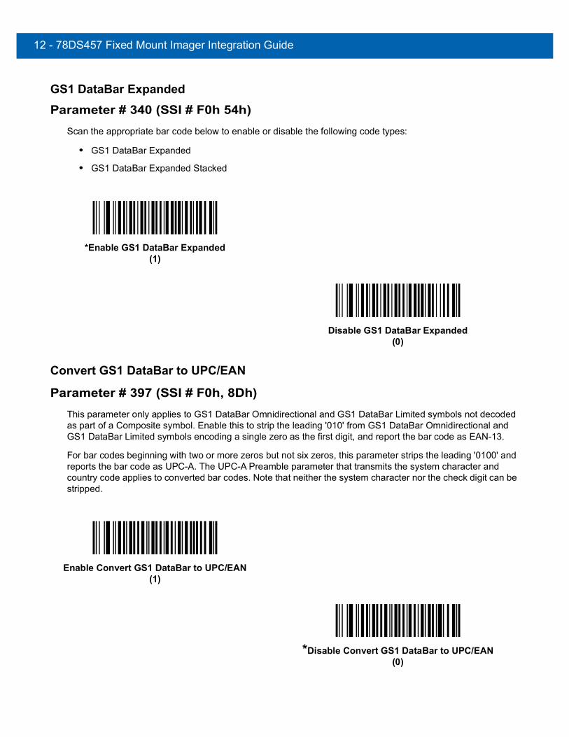
12 - 78DS457 Fixed Mount Imager Integration Guide
GS1 DataBar Expanded
Parameter # 340 (SSI # F0h 54h)Scan the appropriate bar code below to enable or disable the following code types:
• GS1 DataBar Expanded
• GS1 DataBar Expanded Stacked
Convert GS1 DataBar to UPC/EAN
Parameter # 397 (SSI # F0h, 8Dh)This parameter only applies to GS1 DataBar Omnidirectional and GS1 DataBar Limited symbols not decoded as part of a Composite symbol. Enable this to strip the leading '010' from GS1 DataBar Omnidirectional and GS1 DataBar Limited symbols encoding a single zero as the first digit, and report the bar code as EAN-13.
For bar codes beginning with two or more zeros but not six zeros, this parameter strips the leading '0100' and reports the bar code as UPC-A. The UPC-A Preamble parameter that transmits the system character and country code applies to converted bar codes. Note that neither the system character nor the check digit can be stripped.
*Enable GS1 DataBar Expanded(1)
Disable GS1 DataBar Expanded(0)
Enable Convert GS1 DataBar to UPC/EAN(1)
*Disable Convert GS1 DataBar to UPC/EAN(0)

Symbologies12 - 79
Composite
Composite CC-C
Parameter # 341 (SSI # F0h 55h)Scan a bar code below to enable or disable Composite bar codes of type CC-C.
Composite CC-A/B
Parameter # 342 (SSI # F0h 56h)Scan a bar code below to enable or disable Composite bar codes of type CC-A/B.
Enable CC-C(1)
*Disable CC-C(0)
Enable CC-A/B(1)
*Disable CC-A/B(0)

12 - 80DS457 Fixed Mount Imager Integration Guide
Composite TLC-39
Parameter # 371 (SSI # F0h 73h)Scan a bar code below to enable or disable Composite bar codes of type TLC-39.
Enable TLC39(1)
*Disable TLC39(0)

Symbologies12 - 81
UPC Composite Mode
Parameter # 344 (SSI # F0h 58h)UPC symbols can be “linked” with a 2D symbol during transmission as if they were one symbol. There are three options for these symbols:
• Select UPC Never Linked to transmit UPC bar codes regardless of whether a 2D symbol is detected.
• Select UPC Always Linked to transmit UPC bar codes and the 2D portion. If 2D is not present, the UPC bar code does not transmit.
• If Autodiscriminate UPC Composites is selected, the DS457 determines if there is a 2D portion, then transmits the UPC, as well as the 2D portion if present.
*UPC Never Linked(0)
UPC Always Linked(1)
Autodiscriminate UPC Composites(2)
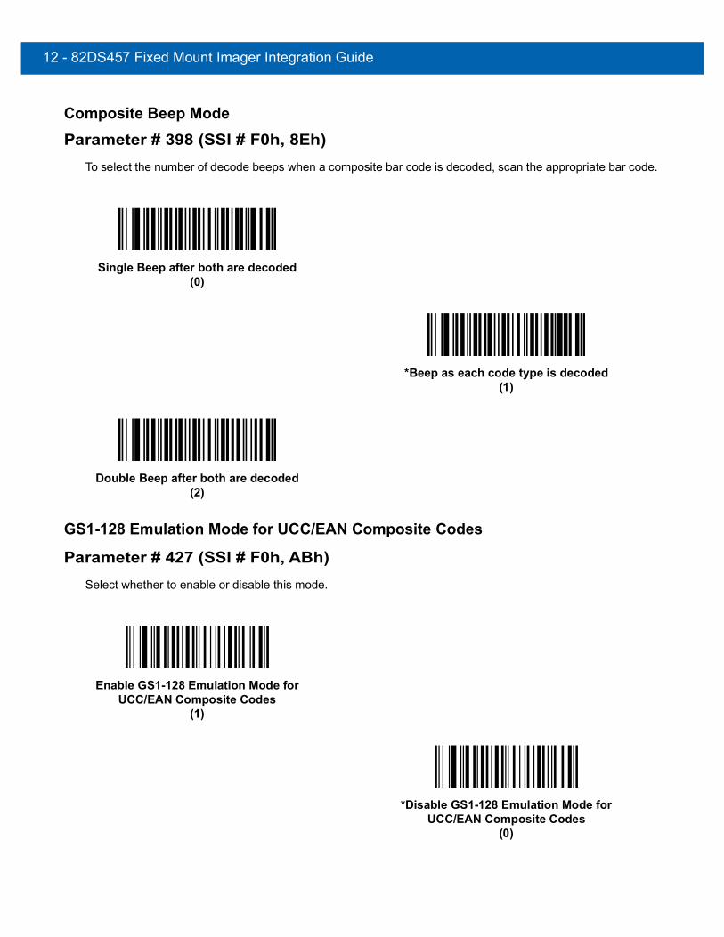
12 - 82DS457 Fixed Mount Imager Integration Guide
Composite Beep Mode
Parameter # 398 (SSI # F0h, 8Eh)To select the number of decode beeps when a composite bar code is decoded, scan the appropriate bar code.
GS1-128 Emulation Mode for UCC/EAN Composite Codes
Parameter # 427 (SSI # F0h, ABh)Select whether to enable or disable this mode.
Single Beep after both are decoded(0)
*Beep as each code type is decoded(1)
Double Beep after both are decoded(2)
Enable GS1-128 Emulation Mode for UCC/EAN Composite Codes
(1)
*Disable GS1-128 Emulation Mode for UCC/EAN Composite Codes
(0)

Symbologies12 - 83
2D Symbologies
Enable/Disable PDF417
Parameter # 15 (SSI # 0Fh)To enable or disable PDF417, scan the appropriate bar code below.
Enable/Disable MicroPDF417
Parameter # 227 (SSI # E3h)To enable or disable MicroPDF417, scan the appropriate bar code below.
*Enable PDF417(1)
Disable PDF417(0)
Enable MicroPDF417(1)
*Disable MicroPDF417(0)
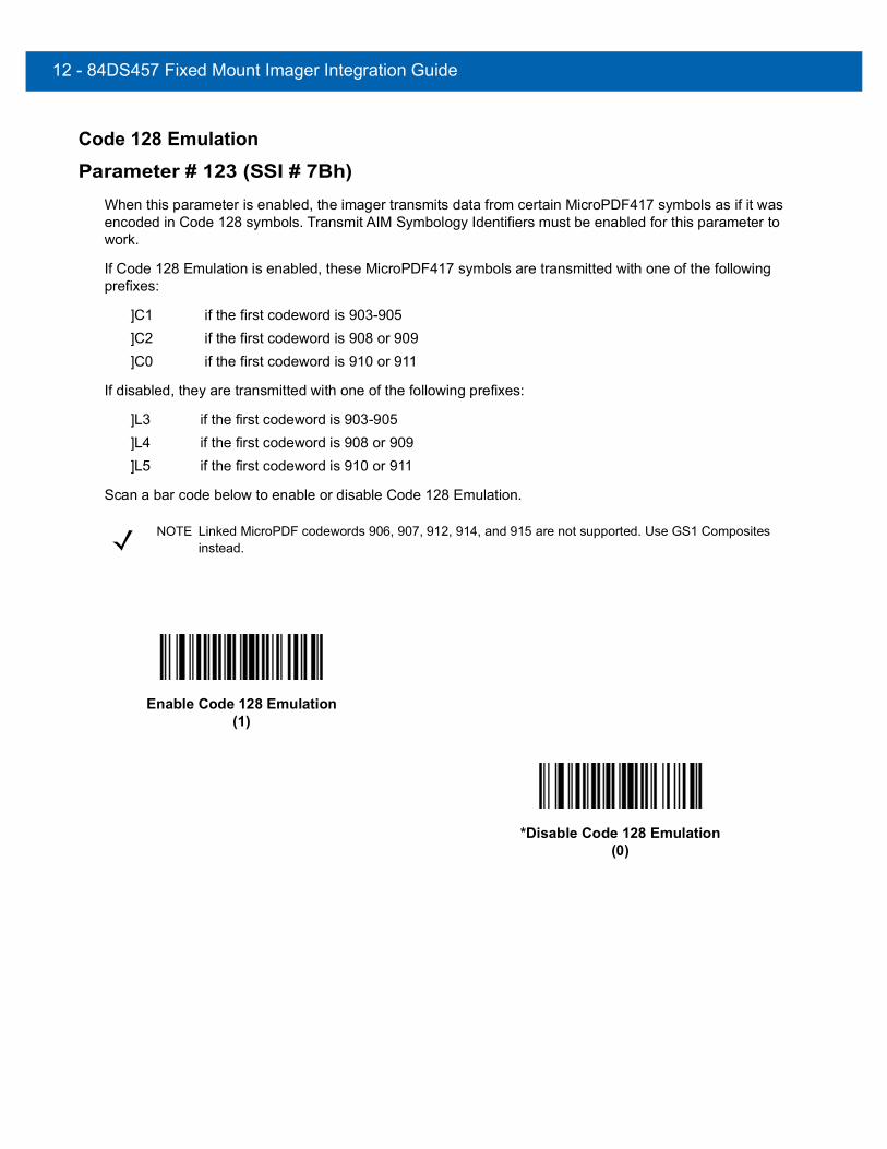
12 - 84DS457 Fixed Mount Imager Integration Guide
Code 128 Emulation
Parameter # 123 (SSI # 7Bh)When this parameter is enabled, the imager transmits data from certain MicroPDF417 symbols as if it was encoded in Code 128 symbols. Transmit AIM Symbology Identifiers must be enabled for this parameter to work.
If Code 128 Emulation is enabled, these MicroPDF417 symbols are transmitted with one of the following prefixes:
]C1 if the first codeword is 903-905]C2 if the first codeword is 908 or 909]C0 if the first codeword is 910 or 911
If disabled, they are transmitted with one of the following prefixes:
]L3 if the first codeword is 903-905]L4 if the first codeword is 908 or 909]L5 if the first codeword is 910 or 911
Scan a bar code below to enable or disable Code 128 Emulation.
NOTE Linked MicroPDF codewords 906, 907, 912, 914, and 915 are not supported. Use GS1 Composites instead.
Enable Code 128 Emulation(1)
*Disable Code 128 Emulation(0)
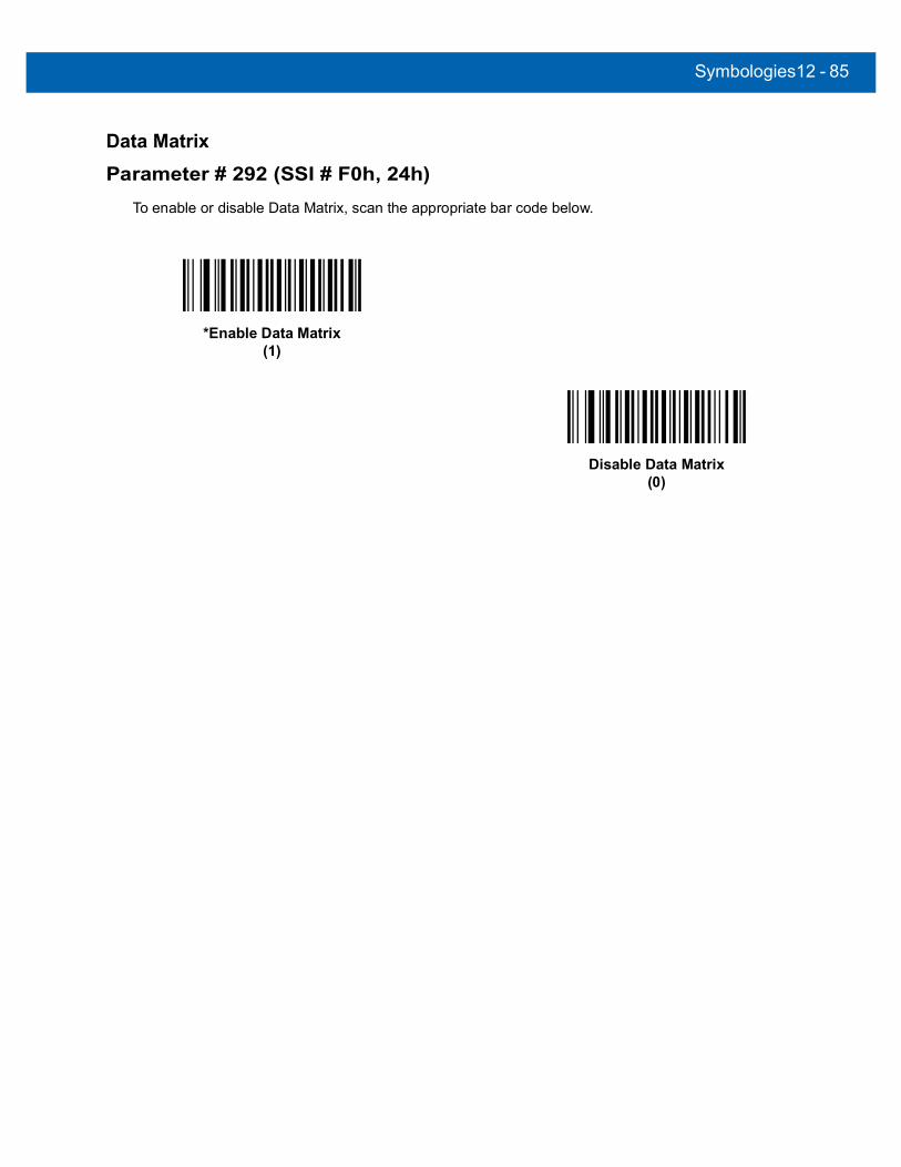
Symbologies12 - 85
Data Matrix
Parameter # 292 (SSI # F0h, 24h)To enable or disable Data Matrix, scan the appropriate bar code below.
*Enable Data Matrix(1)
Disable Data Matrix(0)

12 - 86DS457 Fixed Mount Imager Integration Guide
Data Matrix Inverse
Parameter # 588 (SSI # F1h 4Ch)This parameter sets the Data Matrix inverse imager setting. Options are:
• Regular Only - the imager decodes regular Data Matrix bar codes only.
• Inverse Only - the imager decodes inverse Data Matrix bar codes only.
• Inverse Autodetect - the imager decodes both regular and inverse Data Matrix bar codes.
*Regular(0)
Inverse Only(1)
Inverse Autodetect(2)
(Default for DS457-DP Only)

Symbologies12 - 87
Decode Mirror Images (Data Matrix Only)
Parameter # 537 (SSI # F1h 19h)Select an option for decoding mirror image Data Matrix bar codes:
• Always - decode only Data Matrix bar codes that are mirror images
• Never - do not decode Data Matrix bar codes that are mirror images
• Auto - decode both mirrored and unmirrored Data Matrix bar codes.
Never(0)
Always(1)
*Auto(2)
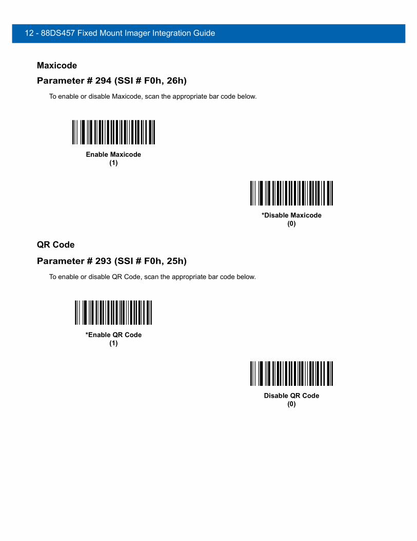
12 - 88DS457 Fixed Mount Imager Integration Guide
Maxicode
Parameter # 294 (SSI # F0h, 26h)To enable or disable Maxicode, scan the appropriate bar code below.
QR Code
Parameter # 293 (SSI # F0h, 25h)To enable or disable QR Code, scan the appropriate bar code below.
Enable Maxicode(1)
*Disable Maxicode(0)
*Enable QR Code(1)
Disable QR Code(0)

Symbologies12 - 89
QR Inverse
Parameter # 587 (SSI # F1h 4Bh)This parameter sets the QR inverse imager setting. Options are:
• Regular Only - the imager decodes regular QR bar codes only.
• Inverse Only - the imager decodes inverse QR bar codes only.
• Inverse Autodetect - the imager decodes both regular and inverse QR bar codes.
*Regular(0)
Inverse Only(1)
Inverse Autodetect(2)

12 - 90DS457 Fixed Mount Imager Integration Guide
MicroQR
Parameter # 573 (SSI # F1h 3Dh)To enable or disable MicroQR, scan the appropriate bar code below.
Aztec
Parameter # 574 (SSI # F1h 3Eh)To enable or disable Aztec, scan the appropriate bar code below.
*Enable MicroQR(1)
Disable MicroQR(0)
*Enable Aztec (1)
Disable Aztec (0)

Symbologies12 - 91
Aztec Inverse
Parameter # 589 (SSI # F1h 4Dh)This parameter sets the Aztec inverse imager setting. Options are:
• Regular Only - the imager decodes regular Aztec bar codes only.
• Inverse Only - the imager decodes inverse Aztec bar codes only.
• Inverse Autodetect - the imager decodes both regular and inverse Aztec bar codes.
Regular(0)
Inverse Only(1)
*Inverse Autodetect(2)

12 - 92DS457 Fixed Mount Imager Integration Guide
Redundancy Level
Parameter # 78 (SSI # 4Eh)The imager offers four levels of decode redundancy. Select higher redundancy levels for decreasing levels of bar code quality. As redundancy levels increase, the imager’s aggressiveness decreases.
Select the redundancy level appropriate for the bar code quality.
Redundancy Level 1The following code types must be successfully read twice before being decoded:
Redundancy Level 2The following code types must be successfully read twice before being decoded:
Redundancy Level 3Code types other than the following must be successfully read twice before being decoded. The following codes must be read three times:
Redundancy Level 4The following code types must be successfully read three times before being decoded:
Code Type Code Length
Codabar 8 characters or less
MSI 4 characters or less
D 2 of 5 8 characters or less
I 2 of 5 8 characters or less
Code Type Code Length
All All
Code Type Code Length
MSI Plessey 4 characters or less
D 2 of 5 8 characters or less
I 2 of 5 8 characters or less
Codabar 8 characters or less
Code Type Code Length
All All
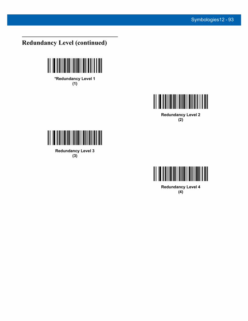
Symbologies12 - 93
Redundancy Level (continued)
*Redundancy Level 1(1)
Redundancy Level 2(2)
Redundancy Level 3(3)
Redundancy Level 4(4)

12 - 94DS457 Fixed Mount Imager Integration Guide
Security Level
Parameter # 77 (SSI # 4Dh)The imager offers four levels of decode security for delta bar codes, which include the Code 128 family, UPC/EAN, and Code 93. Select increasing levels of security for decreasing levels of bar code quality. There is an inverse relationship between security and imager aggressiveness, so choose only that level of security necessary for any given application.
• Security Level 0: This setting allows the imager to operate in its most aggressive state, while providing sufficient security in decoding most “in-spec” bar codes.
• Security Level 1: Select this option if misdecodes occur. This default setting should eliminate most misdecodes.
• Security Level 2: Select this option if Security level 1 fails to eliminate misdecodes.
• Security Level 3: If Security Level 2 was selected and misdecodes still occur, select this security level. Be advised, selecting this option is an extreme measure against mis-decoding severely out of spec bar codes. Selecting this level of security significantly impairs the decoding ability of the imager. If this level of security is necessary, try to improve the quality of the bar codes.
Security Level 0(0)
*Security Level 1(1)
Security Level 2(2)
Security Level 3(3)
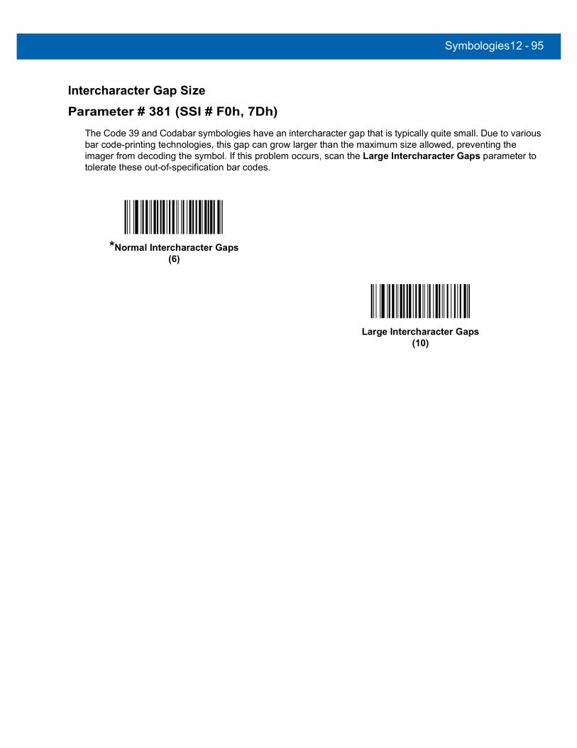
Symbologies12 - 95
Intercharacter Gap Size
Parameter # 381 (SSI # F0h, 7Dh)The Code 39 and Codabar symbologies have an intercharacter gap that is typically quite small. Due to various bar code-printing technologies, this gap can grow larger than the maximum size allowed, preventing the imager from decoding the symbol. If this problem occurs, scan the Large Intercharacter Gaps parameter to tolerate these out-of-specification bar codes.
*Normal Intercharacter Gaps(6)
Large Intercharacter Gaps(10)

12 - 96DS457 Fixed Mount Imager Integration Guide
Macro PDF Features Macro PDF is a special feature for concatenating multiple PDF symbols into one file. The imager can decode symbols that are encoded with this feature, and can store more than 64 kb of decoded data stored in up to 50 Macro PDF symbols.
Macro PDF User IndicationsIn this mode the imager provides the following feedback.
CAUTION When printing, keep each Macro PDF sequence separate, as each sequence has unique identifiers. Do not mix bar codes from several Macro PDF sequences, even if they encode the same data. When scanning Macro PDF sequences, scan the entire Macro PDF sequence without interruption.
Table 12-2 Macro PDF User Indications
User Scans
Passthrough All Symbols
Transmit Any Symbol in Set
Buffer All Symbols
Beep T Beep T Beep T
Last Macro PDF in set Decode Beep Y Decode Beep Y Decode Beep Y
Any Macro PDF in set except last Decode Beep Y Decode Beep Y 2 Short Low N
Macro PDF is not in current set Decode Beep Y 2 Long Low N 2 Long Low N
Invalid formatted Macro PDF Decode Beep Y 2 Long Low N 2 Long Low N
Macro PDF from a set has already been scanned
Decode Beep Y 4 Long Low N 4 Long Low N
Out of Macro PDF memory N/A - 3 Long Low N 3 Long Low N
Any non-Macro PDF scanned during a set N/A - 4 Long Low N 4 Long Low N
Flush Macro PDF Low Hi N 5 Long Low N 5 Long Low Y
Abort Macro PDF High Low High Low
N High Low High Low
N High Low High Low
N
Notes: 1. The beep only sounds if the *BEEPER_ON signal is connected.
2. The column marked T indicates whether the symbol is transmitted to the host. N = No transmission.
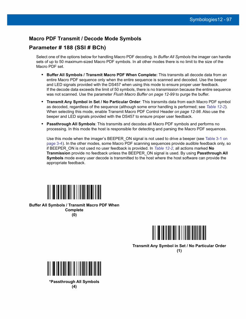
Symbologies12 - 97
Macro PDF Transmit / Decode Mode Symbols
Parameter # 188 (SSI # BCh)Select one of the options below for handling Macro PDF decoding. In Buffer All Symbols the imager can handle sets of up to 50 maximum-sized Macro PDF symbols. In all other modes there is no limit to the size of the Macro PDF set.
• Buffer All Symbols / Transmit Macro PDF When Complete: This transmits all decode data from an entire Macro PDF sequence only when the entire sequence is scanned and decoded. Use the beeper and LED signals provided with the DS457 when using this mode to ensure proper user feedback.If the decode data exceeds the limit of 50 symbols, there is no transmission because the entire sequence was not scanned. Use the parameter Flush Macro Buffer on page 12-99 to purge the buffer.
• Transmit Any Symbol in Set / No Particular Order: This transmits data from each Macro PDF symbol as decoded, regardless of the sequence (although some error handling is performed; see Table 12-2).When selecting this mode, enable Transmit Macro PDF Control Header on page 12-98. Also use the beeper and LED signals provided with the DS457 to ensure proper user feedback.
• Passthrough All Symbols: This transmits and decodes all Macro PDF symbols and performs no processing. In this mode the host is responsible for detecting and parsing the Macro PDF sequences.
Use this mode when the imager’s BEEPER_ON signal is not used to drive a beeper (see Table 3-1 on page 3-4). In the other modes, some Macro PDF scanning sequences provide audible feedback only, so if BEEPER_ON is not used no user feedback is provided. In Table 12-2, all actions marked No Tranmission provide no feedback unless the BEEPER_ON signal is used. By using Passthrough All Symbols mode every user decode is transmitted to the host where the host software can provide the appropriate feedback.
Buffer All Symbols / Transmit Macro PDF When Complete
(0)
Transmit Any Symbol in Set / No Particular Order(1)
*Passthrough All Symbols(4)

12 - 98DS457 Fixed Mount Imager Integration Guide
Transmit Macro PDF Control Header
Parameter # 184 (SSI # B8h)When enabled, this activates transmission of the control header, which contains the segment index and the file ID, in Macro PDF symbols. For example, the field may be: \92800000\725\120\343. The five digits after the \928 are the segment index (or block index), and \725\120\343 is the file ID.
Enable this when selecting Transmit Any Symbol in Set / No Particular Order for the Macro PDF Transmit / Decode Mode Symbols on page 12-97, and disable this when selecting Buffer All Symbols / Transmit Macro PDF When Complete. This parameter has no effect when Passthrough All Symbols is selected.
Escape Characters
Parameter # 233 (SSI # E9h)This enables the backslash (\) character as an Escape character for systems that can process transmissions containing special data sequences. Scan a bar code below to either format special data according to the GLI (Global Label Identifier) protocol, or to disable this parameter. This parameter only affects the data portion of a Macro PDF symbol transmission; the Macro PDF Control Header (if enabled) is always sent with GLI formatting.
Enable Macro PDF Control Header Transmit(1)
*Disable Macro PDF Control Header Transmit(0)
GLI Protocol(2)
*None(0)

Symbologies12 - 99
Flush Macro BufferThis flushes the buffer of all decoded Macro PDF data stored to that point, transmits it to the host device, and aborts from Macro PDF mode.
Abort Macro PDF EntryThis clears all currently-stored Macro PDF data in the buffer without transmission and aborts from Macro PDF mode.
Flush Macro PDF Buffer
Abort Macro PDF Entry

12 - 100DS457 Fixed Mount Imager Integration Guide
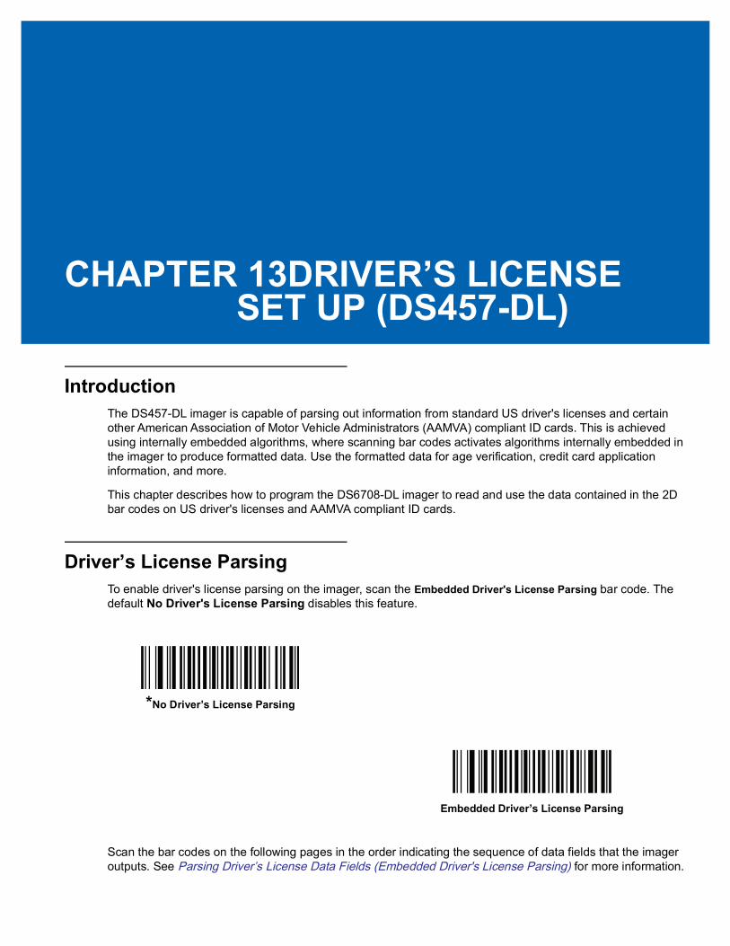
CHAPTER 13DRIVER’S LICENSE SET UP (DS457-DL)
IntroductionThe DS457-DL imager is capable of parsing out information from standard US driver's licenses and certain other American Association of Motor Vehicle Administrators (AAMVA) compliant ID cards. This is achieved using internally embedded algorithms, where scanning bar codes activates algorithms internally embedded in the imager to produce formatted data. Use the formatted data for age verification, credit card application information, and more.
This chapter describes how to program the DS6708-DL imager to read and use the data contained in the 2D bar codes on US driver's licenses and AAMVA compliant ID cards.
Driver’s License ParsingTo enable driver's license parsing on the imager, scan the Embedded Driver's License Parsing bar code. The default No Driver's License Parsing disables this feature.
Scan the bar codes on the following pages in the order indicating the sequence of data fields that the imager outputs. See Parsing Driver’s License Data Fields (Embedded Driver's License Parsing) for more information.
*No Driver’s License Parsing
Embedded Driver’s License Parsing

13 - 2 DS457 Fixed Mount Imager Integration Guide
Parsing Driver’s License Data Fields (Embedded Driver's License Parsing)
To begin programming a parsing rule:
1. Scan Begin New Driver’s License Parse Rule on page 13-3.
2. Scan any of the field bar codes on the following pages, or Send Keystroke (Control Characters and Keyboard Characters) on page 13-23 to complete the parsing rule.
3. After entering the entire rule, scan Save Driver’s License Parse Rule on page 13-3 to save the rule.
To abort the programming sequence at any time during programming, scan Quit Entering Driver’s License Rule on page 13-3. Any previously saved rule is retained.
To erase a programmed saved rule, scan Erase Driver’s License Parse Rules on page 13-3.
Embedded Driver's License Parsing Criteria - Code TypeAfter specifying the fields and their order for the parsed driver's license, you can also apply standard ADF rules to the parsed data using the Parsed Driver’s License criterion bar code in the Advanced Data Formatting Programmer Guide.
See Embedded Driver's License Parsing ADF Example on page 13-20 for a sample ADF rule using this code type criterion.
NOTE Only ONE driver’s license parsing rule may be stored in memory at any time. Saving a new rule replaces the prior rule.
NOTE Only create standard ADF rules on parsed driver's license data when configured for Embedded Driver's License Parsing.
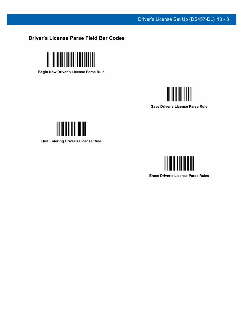
Driver’s License Set Up (DS457-DL) 13 - 3
Driver’s License Parse Field Bar Codes
Begin New Driver’s License Parse Rule
Save Driver’s License Parse Rule
Quit Entering Driver’s License Rule
Erase Driver’s License Parse Rules

13 - 4 DS457 Fixed Mount Imager Integration Guide
Driver’s License Parse Field Bar Codes (continued)The parse fields currently supported begin below. Not all IDs present data in the same format. For example, some IDs may have separate fields for first name, last name, and middle initial, and others may have a single field with the entire name. In addition, some IDs may expire on the subject's birth date and the actual expiration date field may only indicate the year. In order to present data in a consistent format, the following nine bar codes return data that may be calculated from the actual data contained within the ID bar code.
First Name
Middle Name/Initial
Last Name
Name Suffix
Name Prefix
Expiration Date
Birth Date

Driver’s License Set Up (DS457-DL) 13 - 5
Driver’s License Parse Field Bar Codes (continued)
Issue Date
ID Number (Formatted)

13 - 6 DS457 Fixed Mount Imager Integration Guide
AAMVA Parse Field Bar Codes
AAMVA Issuer ID
Full Name
Last Name
First Name
Middle Name / Initial
Name Suffix
Name Prefix

Driver’s License Set Up (DS457-DL) 13 - 7
AAMVA Parse Field Bar Codes (continued)
Mailing Address Line 1
Mailing Address Line 2
Mailing Address City
Mailing Address State
Mailing Address Postal Code
Home Address Line 1
Home Address Line 2

13 - 8 DS457 Fixed Mount Imager Integration Guide
AAMVA Parse Field Bar Codes (continued)
Home Address City
Home Address State
Home Address Postal Code
License ID Number
License Class
License Restrictions
License Endorsements

Driver’s License Set Up (DS457-DL) 13 - 9
AAMVA Parse Field Bar Codes (continued)
Height (Feet and/or Inches)
Height (Centimeters)
Weight (Pounds)
Weight (Kilograms)
Eye Color
Hair Color
License Expiration Date
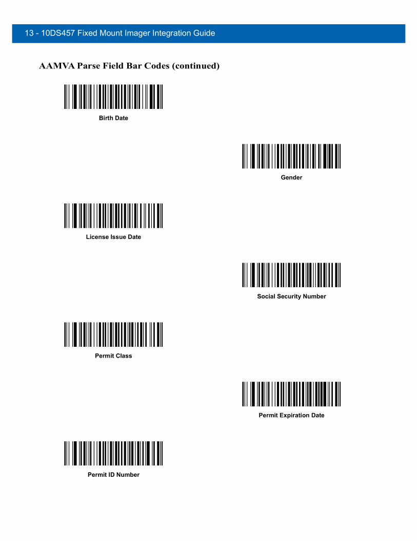
13 - 10DS457 Fixed Mount Imager Integration Guide
AAMVA Parse Field Bar Codes (continued)
Birth Date
Gender
License Issue Date
Social Security Number
Permit Class
Permit Expiration Date
Permit ID Number
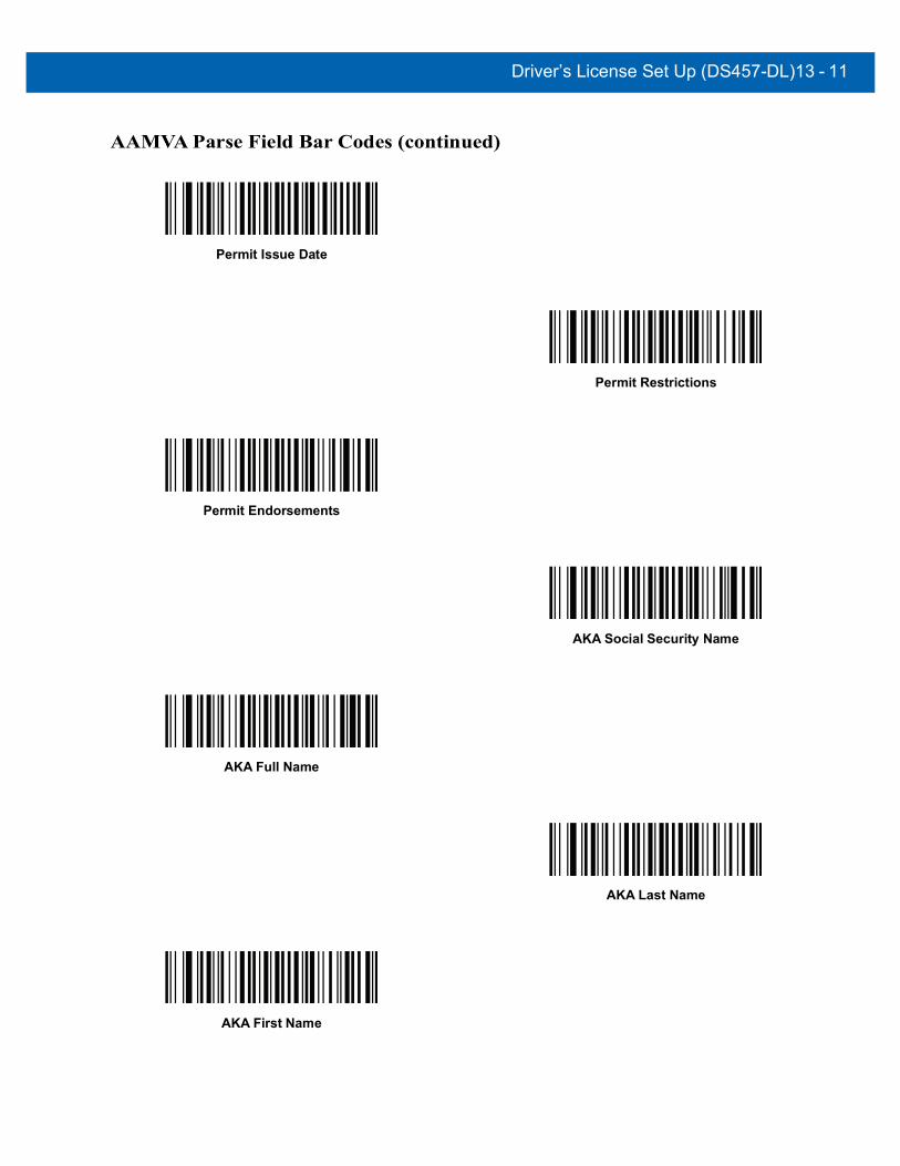
Driver’s License Set Up (DS457-DL)13 - 11
AAMVA Parse Field Bar Codes (continued)
Permit Issue Date
Permit Restrictions
Permit Endorsements
AKA Social Security Name
AKA Full Name
AKA Last Name
AKA First Name

13 - 12DS457 Fixed Mount Imager Integration Guide
AAMVA Parse Field Bar Codes (continued)
AKA Middle Name / Initial
AKA Name Suffix
AKA Name Prefix
AKA Birth Date
Issue Timestamp
Number of Duplicates
Medical Codes

Driver’s License Set Up (DS457-DL)13 - 13
AAMVA Parse Field Bar Codes (continued)
Organ Donor
Nonresident
Customer ID
Weight Range
Document Discriminator
Country
Federal Commission Codes
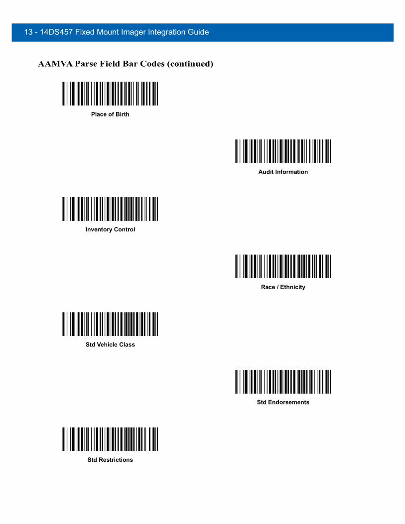
13 - 14DS457 Fixed Mount Imager Integration Guide
AAMVA Parse Field Bar Codes (continued)
Place of Birth
Audit Information
Inventory Control
Race / Ethnicity
Std Vehicle Class
Std Endorsements
Std Restrictions

Driver’s License Set Up (DS457-DL)13 - 15
AAMVA Parse Field Bar Codes (continued)
Class Description
Endorsement Description
Restrictions Description
Height in Inches
Height in Centimeters
Parser Version ID Bar CodesInclude this field to emit embedded parser software version identification
Parser Version ID

13 - 16DS457 Fixed Mount Imager Integration Guide
Parsing Rule ExampleScan the following bar codes in sequence to program the imager to extract and transmit first, middle, and last names; mailing address line 1; mailing address line 2; mailing address city; mailing address state; mailing address postal code; and, date of birth. Then, scan a driver’s license bar code.
NOTE This example applies to RS-232. To use this example with a USB interface, scan Function Key Mapping on page 10-11 in place of the Send Control M (Carriage Return) bar codes.
1
Embedded Driver’s License Parsing
2
Begin New Driver’s License Parse Rule
3
First Name
4
Send Space
5
Middle Name / Initial
6
Send Space

Driver’s License Set Up (DS457-DL)13 - 17
Parsing Rule Example (continued)7
Last Name
8
Send Enter Key
9
Mailing Address Line 1
10
Send Space
11
Mailing Address Line 2
q 12
Send Enter Key

13 - 18DS457 Fixed Mount Imager Integration Guide
Parsing Rule Example (continued)13
Mailing Address City
14
Send Space
15
Mailing Address State
16
Send Space
17
Mailing Address Postal Code

Driver’s License Set Up (DS457-DL)13 - 19
Parsing Rule Example (continued)18
Send Enter Key
19
Birth Date
20
Send Enter Key
21
Save Driver’s Licence Parse Rule

13 - 20DS457 Fixed Mount Imager Integration Guide
Embedded Driver's License Parsing ADF ExampleThis example creates a parsing rule for parsed data configured to result in the format:
Last Name, First Name
1
Begin New Driver’s License Parse Rule
2
Last Name
3
Send ,
4
Send Space
5
First Name
6
Save Driver’s Licence Parse Rule
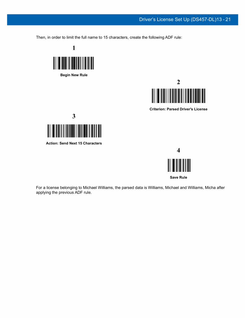
Driver’s License Set Up (DS457-DL)13 - 21
Then, in order to limit the full name to 15 characters, create the following ADF rule:
For a license belonging to Michael Williams, the parsed data is Williams, Michael and Williams, Micha after applying the previous ADF rule.
1
Begin New Rule
2
Criterion: Parsed Driver's License
3
Action: Send Next 15 Characters
4
Save Rule

13 - 22DS457 Fixed Mount Imager Integration Guide
Field Update ProcedureScan the following bar codes in order to perform a field update.
This update COMPLETELY REPLACES prior updates and overrides any embedded parsing software programmed in the imager.
1. Scan Field Update Start.
Field Update Start
2. Scan the entire set of PDF bar codes provided separately.
3. Scan Field Update End.
Field Update End
Scan Erase all Field Updates to completely remove all previous updates. It is not necessary to scan this bar code before performing a normal field update. Scanning this bar code ensures that only the parsing software currently in the imager is used for parsing.
Erase all Field Updates

Driver’s License Set Up (DS457-DL)13 - 23
User Preferences
Set Default ParameterScan this bar code to return all parameters to the default values listed in Table A-1 on page A-1.
Send Keystroke (Control Characters and Keyboard Characters)Control CharactersScan a Send bar code for the keystroke to send.
*Set All Defaults
Send Control A
Send Control B

13 - 24DS457 Fixed Mount Imager Integration Guide
Control Characters (continued)
Send Control C
Send Control D
Send Control E
Send Control F
Send Control G
Send Control H
Send Control I
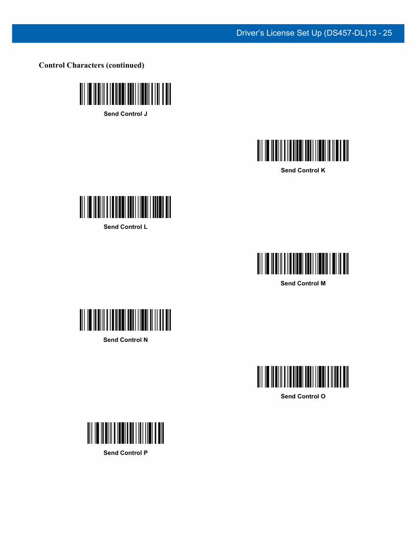
Driver’s License Set Up (DS457-DL)13 - 25
Control Characters (continued)
Send Control J
Send Control K
Send Control L
Send Control M
Send Control N
Send Control O
Send Control P
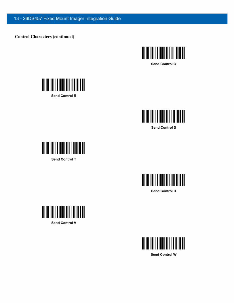
13 - 26DS457 Fixed Mount Imager Integration Guide
Control Characters (continued)
Send Control Q
Send Control R
Send Control S
Send Control T
Send Control U
Send Control V
Send Control W

Driver’s License Set Up (DS457-DL)13 - 27
Control Characters (continued)
Send Control X
Send Control Y
Send Control Z
Send Control [
Send Control \
Send Control ]

13 - 28DS457 Fixed Mount Imager Integration Guide
Keyboard CharactersScan a Send bar code for the keyboard characters to send.
Control Characters (continued)
Send Control 6
Send Control -
Send Space
Send !
Send “
Send #

Driver’s License Set Up (DS457-DL)13 - 29
Keyboard Characters (continued)
Send $
Send %
Send &
Send ‘
Send (
Send )
Send *

13 - 30DS457 Fixed Mount Imager Integration Guide
Keyboard Characters (continued)
Send +
Send ,
Send -
Send .
Send /
Send 0
Send 1

Driver’s License Set Up (DS457-DL)13 - 31
Keyboard Characters (continued)
Send 2
Send 3
Send 4
Send 5
Send 6
Send 7
Send 8

13 - 32DS457 Fixed Mount Imager Integration Guide
Keyboard Characters (continued)
Send 9
Send :
Send ;
Send <
Send =
Send >
Send ?
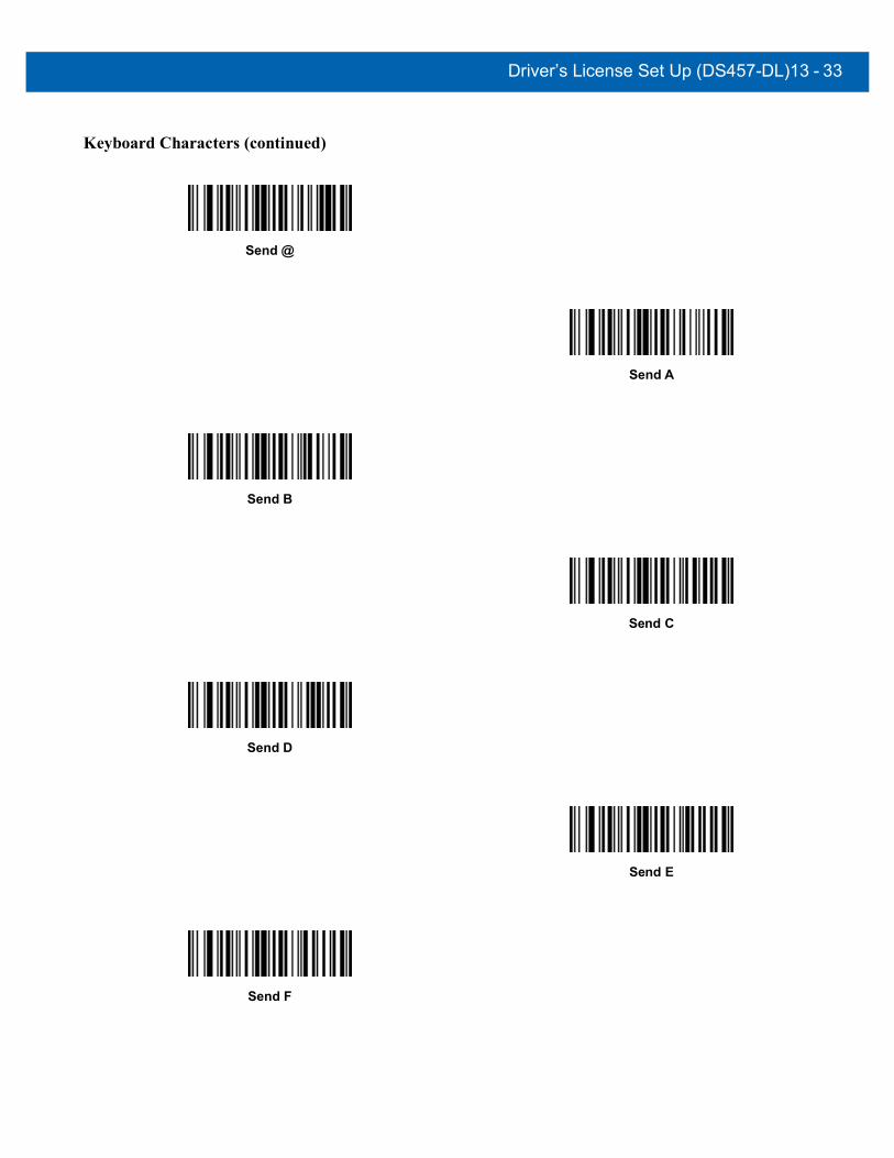
Driver’s License Set Up (DS457-DL)13 - 33
Keyboard Characters (continued)
Send @
Send A
Send B
Send C
Send D
Send E
Send F
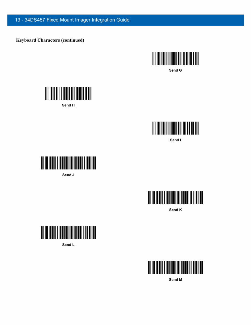
13 - 34DS457 Fixed Mount Imager Integration Guide
Keyboard Characters (continued)
Send G
Send H
Send I
Send J
Send K
Send L
Send M

Driver’s License Set Up (DS457-DL)13 - 35
Keyboard Characters (continued)
Send N
Send O
Send P
Send Q
Send R
Send S
Send T

13 - 36DS457 Fixed Mount Imager Integration Guide
Keyboard Characters (continued)
Send U
Send V
Send W
Send X
Send Y
Send Z
Send [

Driver’s License Set Up (DS457-DL)13 - 37
Keyboard Characters (continued)
Send \
Send ]
Send ^
Send _
Send `
Send a
Send b

13 - 38DS457 Fixed Mount Imager Integration Guide
Keyboard Characters (continued)
Send c
Send d
Send e
Send f
Send g
Send h
Send i

Driver’s License Set Up (DS457-DL)13 - 39
Keyboard Characters (continued)
Send j
Send k
Send l
Send m
Send n
Send o
Send p

13 - 40DS457 Fixed Mount Imager Integration Guide
Keyboard Characters (continued)
Send q
Send r
Send s
Send t
Send u
Send v
Send w
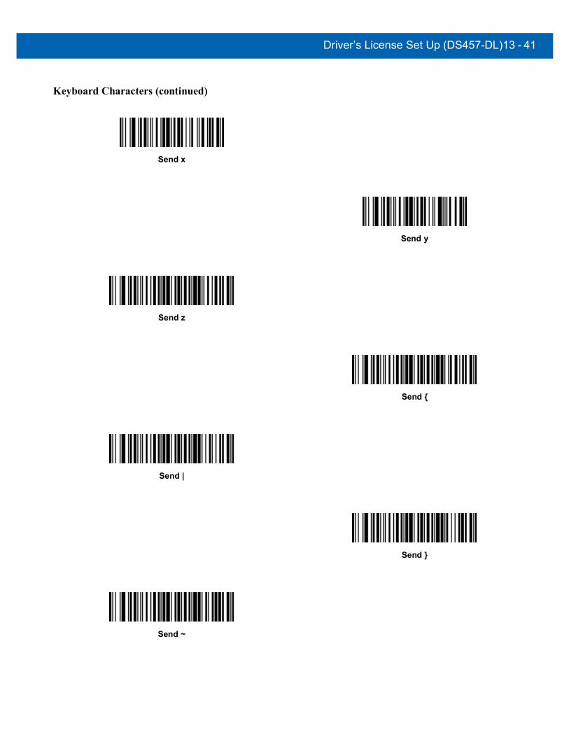
Driver’s License Set Up (DS457-DL)13 - 41
Keyboard Characters (continued)
Send x
Send y
Send z
Send {
Send |
Send }
Send ~

13 - 42DS457 Fixed Mount Imager Integration Guide
Keyboard Characters (continued)
Send Tab Key
Send Enter Key

CHAPTER 14123SCAN
Introduction123Scan is an easy to use, PC-based software tool that enables rapid customized setup of Zebra imagers.
123Scan uses a wizard tool to guide users through a streamlined set up process. Settings are saved in a configuration file that can be distributed via e-mail, electronically downloaded via a USB cable, or used to generate a sheet of scannable programming bar codes.
Additionally 123Scan can upgrade imager firmware, check online to enable support for newly released products, generate a collection of multi-setting bar codes if the number of settings is very large, stage a large number of imagers simultaneously, generate reports with asset tracking information, and create custom products.
123Scan is an easy-to-use, PC-based software tool that enables the quick and easy setup of Zebra imagers. 123Scan uses a wizard tool to guide users through a streamlined set up process. Once parameters are set, the values are saved to a configuration file that can be distributed via e-mail, or used to generate a sheet of programming bar codes that can be scanned.
Communication with 123ScanTo communicate with the 123Scan program which runs on a host computer running a Windows XP SP2 or Windows 7 operating system, use a USB cable to connect the imager to the host computer (see USB Host Connection on page 2-8).

14 - 2 DS457 Fixed Mount Imager Integration Guide
123Scan Requirements• Host computer with Windows XP SP2 or Windows 7
• Imager
• USB cable.
For more information on123Scan, go to: http://www.zebra.com/123Scan
For a 1 minute tour of 123Scan, go to: http://www.zebra.com/ScannerHowToVideos
To see a list of all of our software tools, go to: http://www.zebra.com/scannersoftware
Scanner SDK, Other Software Tools, and VideosTackle all your scanner programming needs with our diversified set of software tools. Whether you need to simply stage a device, or develop a fully featured application with image and data capture as well as asset management, these tools help you every step of the way. To download any of the free tools listed below, go to: http://www.zebra.com/scannersoftware.
• 123Scan configuration utility (described in this chapter)
• Scanner SDK for Windows
• How-to videos
• Virtual COM port driver
• OPOS driver
• JPOS driver
• Scanner user documentation
• Archive of older drivers.

CHAPTER 15ADVANCED DATA FORMATTING
IntroductionAdvanced Data Formatting (ADF) is a means of customizing data before transmission to the host device. Use ADF to edit scan data to suit requirements. Implement ADF by scanning a related series of bar codes which program the imager with ADF rules.
For information and programming bar codes for ADF, refer to the Advanced Data Formatting Programmer Guide, p/n 72E-69680-xx.

15 - 2 DS457 Fixed Mount Imager Integration Guide
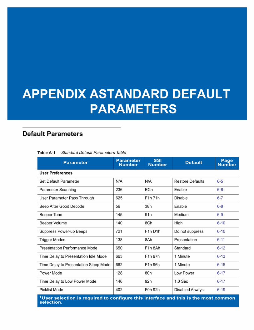
APPENDIX ASTANDARD DEFAULT PARAMETERS
Default Parameters
Table A-1 Standard Default Parameters Table
Parameter Parameter Number
SSI Number Default Page
Number
User Preferences
Set Default Parameter N/A N/A Restore Defaults 6-5
Parameter Scanning 236 ECh Enable 6-6
User Parameter Pass Through 625 F1h 71h Disable 6-7
Beep After Good Decode 56 38h Enable 6-8
Beeper Tone 145 91h Medium 6-9
Beeper Volume 140 8Ch High 6-10
Suppress Power-up Beeps 721 F1h D1h Do not suppress 6-10
Trigger Modes 138 8Ah Presentation 6-11
Presentation Performance Mode 650 F1h 8Ah Standard 6-12
Time Delay to Presentation Idle Mode 663 F1h 97h 1 Minute 6-13
Time Delay to Presentation Sleep Mode 662 F1h 96h 1 Minute 6-15
Power Mode 128 80h Low Power 6-17
Time Delay to Low Power Mode 146 92h 1.0 Sec 6-17
Picklist Mode 402 F0h 92h Disabled Always 6-191User selection is required to configure this interface and this is the most common selection.

A - 2 DS457 Fixed Mount Imager Integration Guide
Decode Session Timeout 136 88h 9.9 Sec 6-19
Timeout Between Decodes, Same Symbol
137 89h 0.6 Sec 6-20
Continuous Bar Code Read 649 F1 89h Disable 6-20
Unique Bar Code Reporting 723 F1h D3h Enable 6-21
Mirrored Image 624 F1h 70h Disable 6-21
Mobile Phone/Display Mode 716 F1h CCh Disable 6-22
Validate Concatenated Parameter Bar Codes
692 F1h B4h Disable 6-22
PDF Prioritization 719 F1h CFh Disable 6-23
PDF Prioritization Timeout 720 F1h D0h 400 ms 6-23
Multicode Mode 677 F1h A5h Disable 6-24
Multicode Expression 661 F1h 95h 1 6-25
Multicode Mode Concatenation 717 F1h, CDh Disable 6-33
Multicode Concatenation Symbology 722 F1h, D2h Concatenate as PDF417
6-34
Miscellaneous Parameters
Transmit Code ID Character 45 2Dh None 6-37
SSI Prefix Value 105 69h <CR> 6-38
SSI Suffix 1 ValueSSI Suffix 2 Value
104106
68h6Ah
<CR><CR>
6-38
Non-SSI Prefix Value 99, 105 63h, 69h <CR><LF> 6-38
Non-SSI Suffix 1 ValueNon-SSI Suffix 2 Value
98, 104100, 106
62h, 68h64h, 6Ah
<CR><LF><CR><LF>
6-38
Scan Data Transmission Format 235 EBh Data as is 6-39
FN1 Substitution Values 103, 109 67h, 6Dh Set 6-40
Transmit “No Read” Message 94 5Eh Disable 6-41
Report Version 6-41
Table A-1 Standard Default Parameters Table (Continued)
Parameter Parameter Number
SSI Number Default Page
Number
1User selection is required to configure this interface and this is the most common selection.

Standard Default Parameters A - 3
Imager Preferences
Decoding Autoexposure 297 F0h 29h Enable 7-5
Decoding Illumination 298 F0h 2Ah Enable 7-6
Decode Aiming Pattern 306 F0h 32h Enable 7-6
Aim Brightness 668 F1h 9Ch 0 7-7
Illumination Brightness 669 F1h 9Dh 10 7-7
Low Light Enhancement 612 F1h 64h Disable 7-8
Power Up Light in Presentation Mode 1198 F8h 04h AEh Disable 7-8
Presentation Mode Field of View 609 F1h 61h Default (Reduced) 7-9
Frame Rate 674 F1h A2h Auto 7-10
Image Capture Autoexposure 360 F0h 68h Enable 7-12
Image Capture Illumination 361 F0h 69h Enable 7-12
Fixed Gain 568 F1h 38h 50 7-13
Exposure Time 567 F4h F1h 37h 100 (10 ms) 7-13
Snapshot Mode Timeout 323 F0h 43h 0 (30 seconds) 7-14
Snapshot Aiming Pattern 300 F0h 2Ch Enable 7-14
Presentation Snapshot by Motion 647 F1h 87h Disable 7-15
Continuous Snapshot 648 F1h 88h Disable 7-15
Image Cropping 301 F0h 2Dh Disable 7-16
Crop to Pixel Addresses 315, 316, 317, 318
F4h F0h 3Bh; F4h F0h 3Ch; F4h F0h 3Dh; F4h F0h 3Eh
0 top, 0 left, 479 bottom, 751 right
7-17
Image Resolution 302 F0h 2Eh Full 7-18
Image Brightness (Target White) 390 F0h 86h 180 7-19
Image File Format Selection 304 F0h 30h JPEG 7-20
JPEG Image Options 299 F0h 2Bh Quality 7-20
JPEG Quality Value 305 F0h 31h 65 7-21
JPEG Size Value 561 F1h 31h 160 (164K) 7-21
Image File Meta Data 693 F1h B5h Disable 7-22
Table A-1 Standard Default Parameters Table (Continued)
Parameter Parameter Number
SSI Number Default Page
Number
1User selection is required to configure this interface and this is the most common selection.

A - 4 DS457 Fixed Mount Imager Integration Guide
Image Enhancement 564 F1h 34h Off 7-22
Image Edge Sharpening 664 F1h 98h Low 7-23
Image Contrast Enhancement 666 F1h 9Ah Off 7-24
Image Rotation 665 F1h 99h 0 7-26
Bits per Pixel (BPP) 303 F0h 2Fh 8 BPP 7-27
Signature Capture 93 5Dh Disable 7-28
Signature Capture Image File Format Selection
313 F0h 39h JPEG 7-29
Signature Capture Bits per Pixel (BPP) 314 F0h 3Ah 8 BPP 7-30
Signature Capture Width 366 F4h F0h 6Eh 400 7-30
Signature Capture Height 367 F4h F0h 6Fh 100 7-31
Signature Capture JPEG Quality 421 F0h A5h 65 7-31
Video Mode Format Selector 916 F2h 94h JPEG 7-31
Video View Finder 324 F0h 44h Disable 7-32
Target Video Frame Size 328 F0h 48h 2200 bytes 7-33
Video View Finder Image Size 329 F0h 49h 1700 bytes 7-33
Video Resolution 667 F1h 9Bh 1/4 resolution 7-34
SSI Host Parameters
Select SSI Host N/A N/A N/A 8-9
Baud Rate 156 9Ch 9600 8-10
Parity 258 9Eh None 8-11
Check Parity 151 97h Disable 8-12
Software Handshaking 159 9Fh ACK/NAK 8-12
Host RTS Line State 154 9Ah Low 8-13
Decode Data Packet Format 238 EEh Send Raw Decode Data
8-13
Host Serial Response Time-out 155 9Bh 2 sec 8-14
Host Character Time-out 239 EFh 200 msec 8-15
Multipacket Option 334 F0h 4Eh Option 1 8-16
Interpacket Delay 335 F0h 4Fh 0 ms 8-17
Table A-1 Standard Default Parameters Table (Continued)
Parameter Parameter Number
SSI Number Default Page
Number
1User selection is required to configure this interface and this is the most common selection.

Standard Default Parameters A - 5
Event Reporting
Decode Event 256 F0h 00h Disable 8-18
Boot Up Event 258 F0h 02h Disable 8-19
Parameter Event 259 F0h 03h Disable 8-19
Serial Host Parameters
Serial Host Types N/A N/A Standard RS-232 9-5
Baud Rate N/A N/A 9600 9-7
Parity Type N/A N/A None 9-9
Data Bits N/A N/A 8-Bit 9-9
Check Receive Errors N/A N/A Enable 9-10
Hardware Handshaking N/A N/A None 9-11
Software Handshaking N/A N/A None 9-13
Host Serial Response Time-out N/A N/A 2 Sec 9-15
RTS Line State N/A N/A Low RTS 9-16
Beep on <BEL> N/A N/A Disable 9-16
Intercharacter Delay N/A N/A 0 msec 9-17
Nixdorf Beep/LED Options N/A N/A Normal Operation 9-18
Ignore Unknown Characters N/A N/A Send Bar Code 9-18
USB Host Parameters
USB Device Type N/A N/A USB HID Keyboard 10-3
Symbol Native API (SNAPI) Status Handshaking
N/A N/A Enable 10-5
USB Country Keyboard Types (Country Codes)
N/A N/A North American 10-6
USB Keystroke Delay N/A N/A No Delay 10-8
USB CAPS Lock Override N/A N/A Disable 10-8
USB Ignore Unknown Characters N/A N/A Enable 10-9
Emulate Keypad N/A N/A Disable 10-9
Emulate Keypad with Leading Zero N/A N/A Disable 10-10
Quick Keypad Emulation N/A N/A Disable 10-10
Table A-1 Standard Default Parameters Table (Continued)
Parameter Parameter Number
SSI Number Default Page
Number
1User selection is required to configure this interface and this is the most common selection.
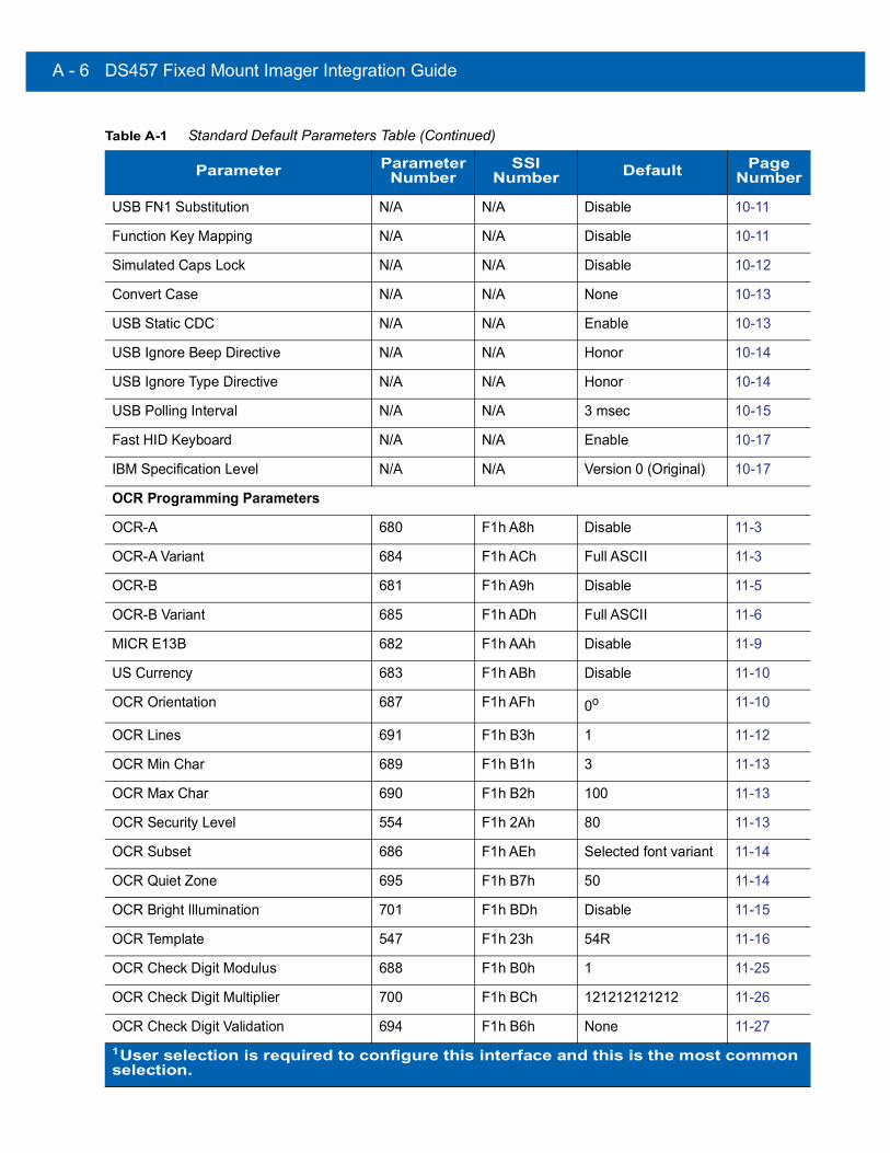
A - 6 DS457 Fixed Mount Imager Integration Guide
USB FN1 Substitution N/A N/A Disable 10-11
Function Key Mapping N/A N/A Disable 10-11
Simulated Caps Lock N/A N/A Disable 10-12
Convert Case N/A N/A None 10-13
USB Static CDC N/A N/A Enable 10-13
USB Ignore Beep Directive N/A N/A Honor 10-14
USB Ignore Type Directive N/A N/A Honor 10-14
USB Polling Interval N/A N/A 3 msec 10-15
Fast HID Keyboard N/A N/A Enable 10-17
IBM Specification Level N/A N/A Version 0 (Original) 10-17
OCR Programming Parameters
OCR-A 680 F1h A8h Disable 11-3
OCR-A Variant 684 F1h ACh Full ASCII 11-3
OCR-B 681 F1h A9h Disable 11-5
OCR-B Variant 685 F1h ADh Full ASCII 11-6
MICR E13B 682 F1h AAh Disable 11-9
US Currency 683 F1h ABh Disable 11-10
OCR Orientation 687 F1h AFh 0o 11-10
OCR Lines 691 F1h B3h 1 11-12
OCR Min Char 689 F1h B1h 3 11-13
OCR Max Char 690 F1h B2h 100 11-13
OCR Security Level 554 F1h 2Ah 80 11-13
OCR Subset 686 F1h AEh Selected font variant 11-14
OCR Quiet Zone 695 F1h B7h 50 11-14
OCR Bright Illumination 701 F1h BDh Disable 11-15
OCR Template 547 F1h 23h 54R 11-16
OCR Check Digit Modulus 688 F1h B0h 1 11-25
OCR Check Digit Multiplier 700 F1h BCh 121212121212 11-26
OCR Check Digit Validation 694 F1h B6h None 11-27
Table A-1 Standard Default Parameters Table (Continued)
Parameter Parameter Number
SSI Number Default Page
Number
1User selection is required to configure this interface and this is the most common selection.
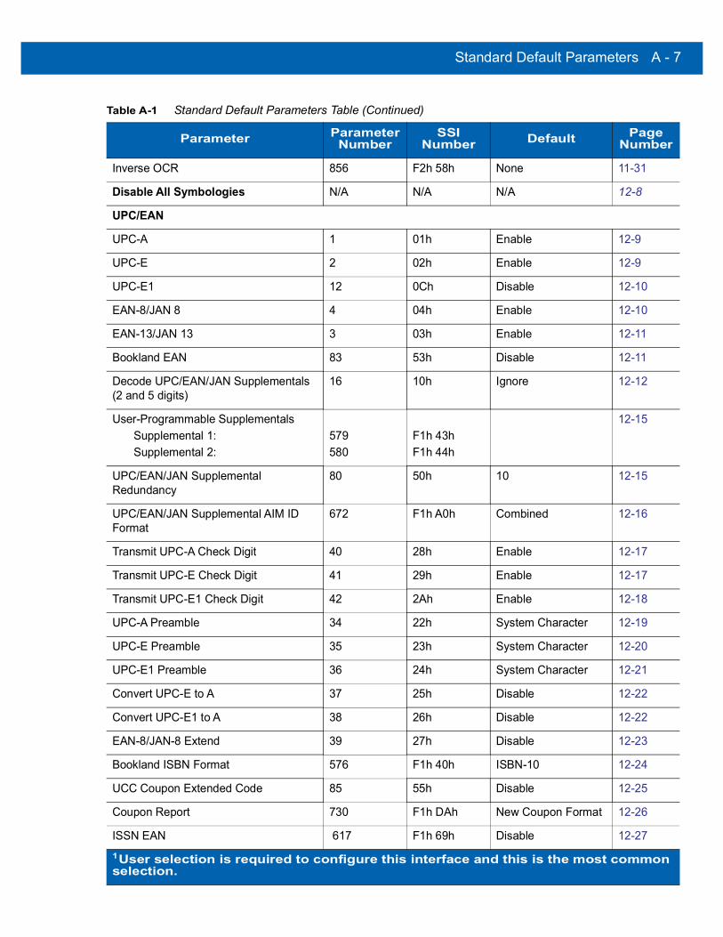
Standard Default Parameters A - 7
Inverse OCR 856 F2h 58h None 11-31
Disable All Symbologies N/A N/A N/A 12-8
UPC/EAN
UPC-A 1 01h Enable 12-9
UPC-E 2 02h Enable 12-9
UPC-E1 12 0Ch Disable 12-10
EAN-8/JAN 8 4 04h Enable 12-10
EAN-13/JAN 13 3 03h Enable 12-11
Bookland EAN 83 53h Disable 12-11
Decode UPC/EAN/JAN Supplementals (2 and 5 digits)
16 10h Ignore 12-12
User-Programmable SupplementalsSupplemental 1: Supplemental 2:
579580
F1h 43hF1h 44h
12-15
UPC/EAN/JAN Supplemental Redundancy
80 50h 10 12-15
UPC/EAN/JAN Supplemental AIM ID Format
672 F1h A0h Combined 12-16
Transmit UPC-A Check Digit 40 28h Enable 12-17
Transmit UPC-E Check Digit 41 29h Enable 12-17
Transmit UPC-E1 Check Digit 42 2Ah Enable 12-18
UPC-A Preamble 34 22h System Character 12-19
UPC-E Preamble 35 23h System Character 12-20
UPC-E1 Preamble 36 24h System Character 12-21
Convert UPC-E to A 37 25h Disable 12-22
Convert UPC-E1 to A 38 26h Disable 12-22
EAN-8/JAN-8 Extend 39 27h Disable 12-23
Bookland ISBN Format 576 F1h 40h ISBN-10 12-24
UCC Coupon Extended Code 85 55h Disable 12-25
Coupon Report 730 F1h DAh New Coupon Format 12-26
ISSN EAN 617 F1h 69h Disable 12-27
Table A-1 Standard Default Parameters Table (Continued)
Parameter Parameter Number
SSI Number Default Page
Number
1User selection is required to configure this interface and this is the most common selection.

A - 8 DS457 Fixed Mount Imager Integration Guide
Code 128
Code 128 8 08h Enable 12-28
Set Length(s) for Code 128 209, 210 D1h D2h Any Length 12-28
GS1-128 (UCC/EAN-128) 14 0Eh Enable 12-30
ISBT 128 84 54h Enable 12-30
ISBT Concatenation 577 F1h 41h Disable 12-31
Check ISBT Table 578 F1h 42h Enable 12-32
ISBT Concatenation Redundancy 223 DFh 10 12-32
Code 128 Security Level 751 F3h EFh Security Level 1 12-33
Code 39
Code 39 0 00h Enable 12-34
Trioptic Code 39 13 0Dh Disable 12-34
Convert Code 39 to Code 32 (Italian Pharmacy Code)
86 56h Disable 12-35
Code 32 Prefix 231 E7h Disable 12-35
Set Length(s) for Code 39 18, 19 12h 13h 2 to 55 12-36
Code 39 Check Digit Verification 48 30h Disable 12-37
Transmit Code 39 Check Digit 43 2Bh Disable 12-38
Code 39 Full ASCII Conversion 17 11h Disable 12-38
Buffer Code 39 113 71h Disable 12-39
Code 39 Security Level 750 F3h EEh Security Level 1 12-42
Code 93
Code 93 9 09h Disable 12-43
Set Length(s) for Code 93 26, 27 1Ah 1Bh 4 to 55 12-43
Code 11
Code 11 10 0Ah Disable 12-45
Set Lengths for Code 11 28, 29 1Ch 1Dh 4 to 55 12-45
Code 11 Check Digit Verification 52 34h Disable 12-47
Transmit Code 11 Check Digit(s) 47 2Fh Disable 12-48
Table A-1 Standard Default Parameters Table (Continued)
Parameter Parameter Number
SSI Number Default Page
Number
1User selection is required to configure this interface and this is the most common selection.

Standard Default Parameters A - 9
Interleaved 2 of 5 (ITF)
Interleaved 2 of 5 (ITF) 6 06h Enable 12-48
Set Lengths for I 2 of 5 22, 23 16h 17h Range 6 - 55 12-49
I 2 of 5 Check Digit Verification 49 31h Disable 12-50
Transmit I 2 of 5 Check Digit 44 2Ch Disable 12-51
Convert I 2 of 5 to EAN 13 82 52h Disable 12-51
I 2 of 5 Security Level 1121 Security Level 1 12-52
Discrete 2 of 5 (DTF)
Discrete 2 of 5 5 05h Disable 12-53
Set Length(s) for D 2 of 5 20, 21 14h 15h 12 12-53
Codabar (NW - 7)
Codabar 7 07h Disable 12-55
Set Lengths for Codabar 24, 25 18h 19h 5 to 55 12-55
CLSI Editing 54 36h Disable 12-57
NOTIS Editing 55 37h Disable 12-57
Codabar Upper or Lower Case Start/Stop Characters Transmission
855 F2h 57h Upper Case 12-58
MSI
MSI 11 0Bh Disable 12-59
Set Length(s) for MSI 30, 31 1Eh 1Fh 4 to 55 12-59
MSI Check Digits 50 32h One 12-61
Transmit MSI Check Digit 46 2Eh Disable 12-62
MSI Check Digit Algorithm 51 33h Mod 10/Mod 10 12-62
Chinese 2 of 5
Chinese 2 of 5 408 F0h 98h Disable 12-63
Matrix 2 of 5
Matrix 2 of 5 618 F1h 6Ah Disable 12-63
Matrix 2 of 5 Lengths 619, 620 F1h 6BhF1h 6Ch
1 Length: 14 12-64
Matrix 2 of 5 Check Digit 622 F1h 6Eh Disable 12-65
Table A-1 Standard Default Parameters Table (Continued)
Parameter Parameter Number
SSI Number Default Page
Number
1User selection is required to configure this interface and this is the most common selection.

A - 10 DS457 Fixed Mount Imager Integration Guide
Transmit Matrix 2 of 5 Check Digit 623 F1h 6Fh Disable 12-65
Korean 3 of 5
Korean 3 of 5 581 F1h 45h Disable 12-66
Inverse 1D 586 F1h 4Ah DS457-SR/HD/DL: RegularDS457-DP: Inverse Autodetect
12-67
Postal Codes
US Postnet 89 59h Disable 12-68
US Planet 90 5Ah Disable 12-68
Transmit US Postal Check Digit 95 5Fh Enable 12-69
UK Postal 91 5Bh Disable 12-69
Transmit UK Postal Check Digit 96 60h Enable 12-70
Japan Postal 290 F0h 22h Disable 12-70
Australia Post 291 F0h 23h Disable 12-71
Australia Post Format 718 F1h CEh Autodiscriminate 12-72
Netherlands KIX Code 326 F0h 46h Disable 12-73
USPS 4CB/One Code/Intelligent Mail 592 F1h 50h Disable 12-74
UPU FICS Postal 611 F1h 63h Disable 12-74
GS1 DataBar (formerly RSS, Reduced Space Symbology)
GS1 DataBar (GS1 DataBar Omnidirectional, GS1 DataBar Truncated, GS1 DataBar Stacked, GS1 DataBar Stacked Omnidirectional)
338 F0h 52h Enable 12-75
GS1 DataBar Limited 339 F0h 53h Enable 12-76
GS1 DataBar Limited Security Level 728 F1h D8h 3 12-77
GS1 DataBar Expanded (GS1 DataBar Expanded, GS1 DataBar Expanded Stacked)
340 F0h 54h Enable 12-78
Convert GS1 DataBar to UPC/EAN 397 F0h 8Dh Disable 12-78
Table A-1 Standard Default Parameters Table (Continued)
Parameter Parameter Number
SSI Number Default Page
Number
1User selection is required to configure this interface and this is the most common selection.

Standard Default Parameters A - 11
Composite
Composite CC-C 341 F0h 55h Disable 12-79
Composite CC-A/B 342 F0h 56h Disable 12-79
Composite TLC-39 371 F0h 73h Disable 12-80
UPC Composite Mode 344 F0h 58h Never Linked 12-81
Composite Beep Mode 398 F0h 8Eh Beep As Each Code Type is Decoded
12-82
GS1-128 Emulation Mode for UCC/EAN Composite Codes
427 F0h ABh Disable 12-82
2D Symbologies
PDF417 15 0Fh Enable 12-83
MicroPDF417 227 E3h Disable 12-83
Code 128 Emulation 123 7Bh Disable 12-84
Data Matrix 292 F0h 24h Enable 12-85
Data Matrix Inverse 588 F1h 4Ch DS457-SR/HD/DL: RegularDS457-DP: Inverse Autodetect
12-86
Decode Mirror Images (Data Matrix Only)
537 F1h, 19h Auto 12-87
Maxicode 294 F0h 26h Disable 12-88
QR Code 293 F0h 25h Enable 12-88
QR Inverse 587 F1h 4Bh Regular 12-89
MicroQR 573 F1h 3Dh Enable 12-90
Aztec 574 F1h 3Eh Enable 12-90
Aztec Inverse 589 F1h 4Dh Inverse Autodetect 12-91
Symbology-Specific Security Levels
Redundancy Level 78 4Eh 1 12-92
Security Level 77 4Dh 1 12-94
Intercharacter Gap Size 381 F0h 7Dh Normal 12-95
Table A-1 Standard Default Parameters Table (Continued)
Parameter Parameter Number
SSI Number Default Page
Number
1User selection is required to configure this interface and this is the most common selection.

A - 12 DS457 Fixed Mount Imager Integration Guide
Macro PDF
Macro PDF Transmit/Decode Mode Symbols
188 BCh Passthrough Mode 12-97
Transmit Macro PDF Control Header 184 B8h Disable 12-98
Escape Characters 233 E9h None 12-98
Flush Macro PDF Buffer N/A N/A N/A 12-99
Abort Macro PDF Entry N/A N/A N/A 12-99
Table A-1 Standard Default Parameters Table (Continued)
Parameter Parameter Number
SSI Number Default Page
Number
1User selection is required to configure this interface and this is the most common selection.

Standard Default Parameters A - 13
Reserved ParametersThe DS457 reports the following parameters, however these parameters are reserved for future use.
• 0x20
• 0x21
• 0x3A
• 0x3B
• 0x3C
• 0x3D
• 0x3E
• 0x3F
• 0x40
• 0x41
• 0x42
• 0x45
• 0x71
• 0xCF
• 0xD0
• 0xD1
• 0xD2
• 0xD5
• 0xEA
• 0xF0, 0x01
• 0xF0, 0x04
• 0xF0, 0x05
• 0xF0, 0x28
• 0xF0, 0x94
• 0xF0, 0x96
• 0xF0, 0x97
• 0xF0, 0x98
• 0xF0, 0x99
• 0xF0, 0xA8
• 0xF0, 0xA9

A - 14 DS457 Fixed Mount Imager Integration Guide
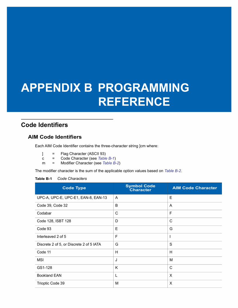
APPENDIX B PROGRAMMING REFERENCE
Code Identifiers
AIM Code IdentifiersEach AIM Code Identifier contains the three-character string ]cm where:
] = Flag Character (ASCII 93)c = Code Character (see Table B-1)m = Modifier Character (see Table B-2)
The modifier character is the sum of the applicable option values based on Table B-2.
Table B-1 Code Characters
Code Type Symbol Code Character AIM Code Character
UPC-A, UPC-E, UPC-E1, EAN-8, EAN-13 A E
Code 39, Code 32 B A
Codabar C F
Code 128, ISBT 128 D C
Code 93 E G
Interleaved 2 of 5 F I
Discrete 2 of 5, or Discrete 2 of 5 IATA G S
Code 11 H H
MSI J M
GS1-128 K C
Bookland EAN L X
Trioptic Code 39 M X
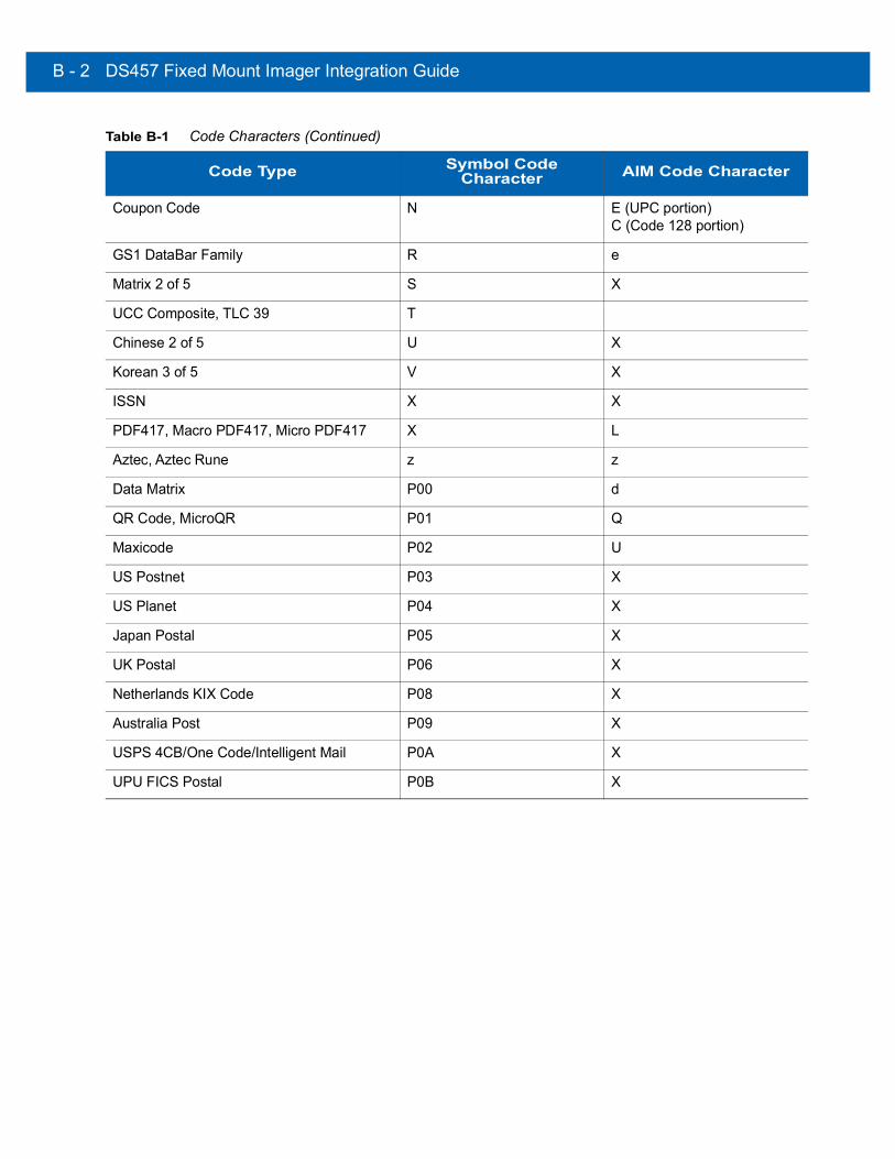
B - 2 DS457 Fixed Mount Imager Integration Guide
Coupon Code N E (UPC portion)C (Code 128 portion)
GS1 DataBar Family R e
Matrix 2 of 5 S X
UCC Composite, TLC 39 T
Chinese 2 of 5 U X
Korean 3 of 5 V X
ISSN X X
PDF417, Macro PDF417, Micro PDF417 X L
Aztec, Aztec Rune z z
Data Matrix P00 d
QR Code, MicroQR P01 Q
Maxicode P02 U
US Postnet P03 X
US Planet P04 X
Japan Postal P05 X
UK Postal P06 X
Netherlands KIX Code P08 X
Australia Post P09 X
USPS 4CB/One Code/Intelligent Mail P0A X
UPU FICS Postal P0B X
Table B-1 Code Characters (Continued)
Code Type Symbol Code Character AIM Code Character
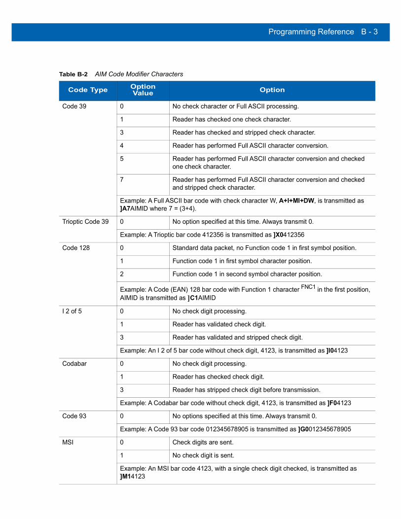
Programming Reference B - 3
Table B-2 AIM Code Modifier Characters
Code Type Option Value Option
Code 39 0 No check character or Full ASCII processing.
1 Reader has checked one check character.
3 Reader has checked and stripped check character.
4 Reader has performed Full ASCII character conversion.
5 Reader has performed Full ASCII character conversion and checked one check character.
7 Reader has performed Full ASCII character conversion and checked and stripped check character.
Example: A Full ASCII bar code with check character W, A+I+MI+DW, is transmitted as ]A7AIMID where 7 = (3+4).
Trioptic Code 39 0 No option specified at this time. Always transmit 0.
Example: A Trioptic bar code 412356 is transmitted as ]X0412356
Code 128 0 Standard data packet, no Function code 1 in first symbol position.
1 Function code 1 in first symbol character position.
2 Function code 1 in second symbol character position.
Example: A Code (EAN) 128 bar code with Function 1 character FNC1 in the first position, AIMID is transmitted as ]C1AIMID
I 2 of 5 0 No check digit processing.
1 Reader has validated check digit.
3 Reader has validated and stripped check digit.
Example: An I 2 of 5 bar code without check digit, 4123, is transmitted as ]I04123
Codabar 0 No check digit processing.
1 Reader has checked check digit.
3 Reader has stripped check digit before transmission.
Example: A Codabar bar code without check digit, 4123, is transmitted as ]F04123
Code 93 0 No options specified at this time. Always transmit 0.
Example: A Code 93 bar code 012345678905 is transmitted as ]G0012345678905
MSI 0 Check digits are sent.
1 No check digit is sent.
Example: An MSI bar code 4123, with a single check digit checked, is transmitted as ]M14123
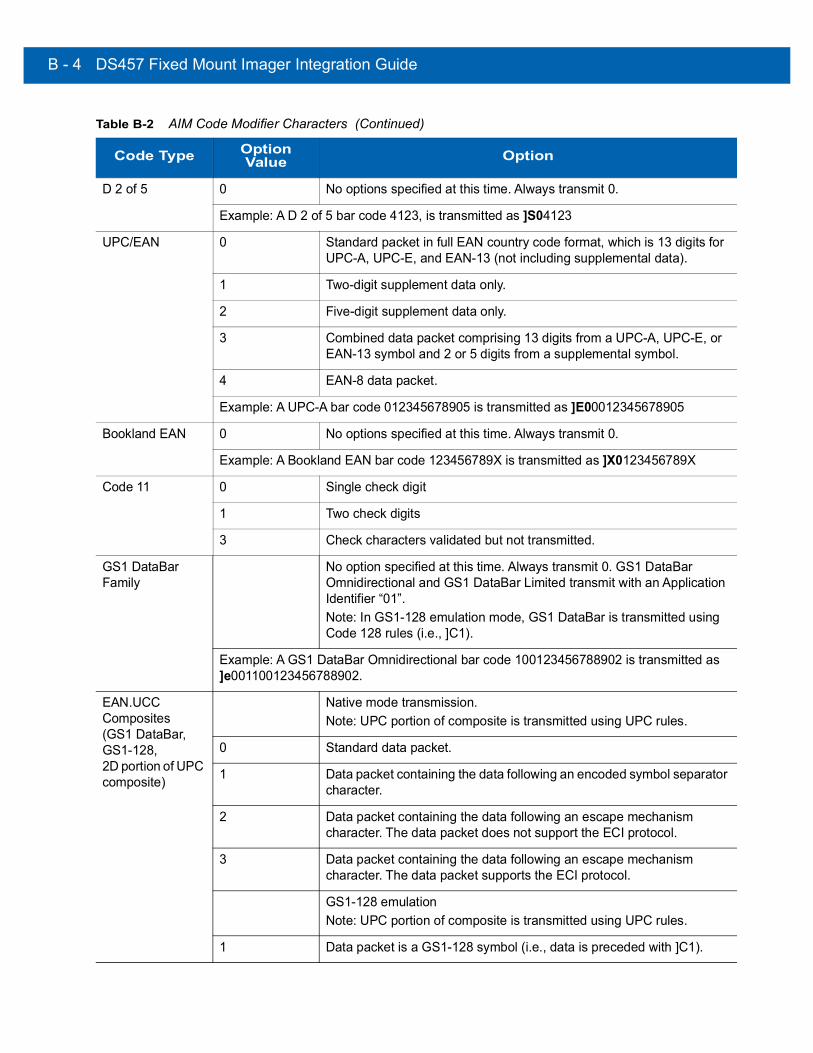
B - 4 DS457 Fixed Mount Imager Integration Guide
D 2 of 5 0 No options specified at this time. Always transmit 0.
Example: A D 2 of 5 bar code 4123, is transmitted as ]S04123
UPC/EAN 0 Standard packet in full EAN country code format, which is 13 digits for UPC-A, UPC-E, and EAN-13 (not including supplemental data).
1 Two-digit supplement data only.
2 Five-digit supplement data only.
3 Combined data packet comprising 13 digits from a UPC-A, UPC-E, or EAN-13 symbol and 2 or 5 digits from a supplemental symbol.
4 EAN-8 data packet.
Example: A UPC-A bar code 012345678905 is transmitted as ]E00012345678905
Bookland EAN 0 No options specified at this time. Always transmit 0.
Example: A Bookland EAN bar code 123456789X is transmitted as ]X0123456789X
Code 11 0 Single check digit
1 Two check digits
3 Check characters validated but not transmitted.
GS1 DataBar Family
No option specified at this time. Always transmit 0. GS1 DataBar Omnidirectional and GS1 DataBar Limited transmit with an Application Identifier “01”.Note: In GS1-128 emulation mode, GS1 DataBar is transmitted using Code 128 rules (i.e., ]C1).
Example: A GS1 DataBar Omnidirectional bar code 100123456788902 is transmitted as ]e001100123456788902.
EAN.UCC Composites (GS1 DataBar, GS1-128, 2D portion of UPC composite)
Native mode transmission.Note: UPC portion of composite is transmitted using UPC rules.
0 Standard data packet.
1 Data packet containing the data following an encoded symbol separator character.
2 Data packet containing the data following an escape mechanism character. The data packet does not support the ECI protocol.
3 Data packet containing the data following an escape mechanism character. The data packet supports the ECI protocol.
GS1-128 emulationNote: UPC portion of composite is transmitted using UPC rules.
1 Data packet is a GS1-128 symbol (i.e., data is preceded with ]C1).
Table B-2 AIM Code Modifier Characters (Continued)
Code Type Option Value Option

Programming Reference B - 5
PDF417, Micro PDF417
0 Reader set to conform to protocol defined in 1994 PDF417 symbology specifications. Note: When this option is transmitted, the receiver cannot reliably determine whether ECIs have been invoked or whether data byte 92DEC has been doubled in transmission.
1 Reader set to follow the ECI protocol (Extended Channel Interpretation). All data characters 92DEC are doubled.
2 Reader set for Basic Channel operation (no escape character transmission protocol). Data characters 92DEC are not doubled. Note: When imagers are set to this mode, unbuffered Macro symbols and symbols requiring the imager to convey ECI escape sequences cannot be transmitted.
3 The bar code contains a GS1-128 symbol, and the first codeword is 903-907, 912, 914, 915.
4 The bar code contains a GS1-128 symbol, and the first codeword is in the range 908-909.
5 The bar code contains a GS1-128 symbol, and the first codeword is in the range 910-911.
Example: A PDF417 bar code ABCD, with no transmission protocol enabled, is transmitted as ]L2ABCD.
Data Matrix 0 ECC 000-140, not supported.
1 ECC 200.
2 ECC 200, FNC1 in first or fifth position.
3 ECC 200, FNC1 in second or sixth position.
4 ECC 200, ECI protocol implemented.
5 ECC 200, FNC1 in first or fifth position, ECI protocol implemented.
6 ECC 200, FNC1 in second or sixth position, ECI protocol implemented.
MaxiCode 0 Symbol in Mode 4 or 5.
1 Symbol in Mode 2 or 3.
2 Symbol in Mode 4 or 5, ECI protocol implemented.
3 Symbol in Mode 2 or 3, ECI protocol implemented in secondary message.
Table B-2 AIM Code Modifier Characters (Continued)
Code Type Option Value Option

B - 6 DS457 Fixed Mount Imager Integration Guide
QR Code 0 Model 1 symbol.
1 Model 2 / MicroQR symbol, ECI protocol not implemented.
2 Model 2 symbol, ECI protocol implemented.
3 Model 2 symbol, ECI protocol not implemented, FNC1 implied in first position.
4 Model 2 symbol, ECI protocol implemented, FNC1 implied in first position.
5 Model 2 symbol, ECI protocol not implemented, FNC1 implied in second position.
6 Model 2 symbol, ECI protocol implemented, FNC1 implied in second position.
Aztec 0 Aztec symbol.
C Aztec Rune symbol.
Table B-2 AIM Code Modifier Characters (Continued)
Code Type Option Value Option

APPENDIX CSAMPLE BAR CODES
Code 39
UPC/EAN
UPC-A, 100 %
EAN-13, 100 %
123ABC
0 12345 67890 5
3 456789 012340
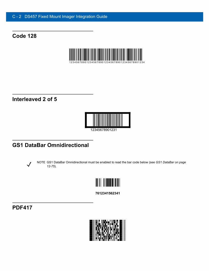
C - 2 DS457 Fixed Mount Imager Integration Guide
Code 128
Interleaved 2 of 5
GS1 DataBar Omnidirectional
7612341562341
PDF417
1 2 3 4 5 6 7 8 9 0 1 2 3 4 5 6 7 8 90 1 2 3 4 5 6 7 8 9 0 1 2 3 4 5 6 7 8 9 0 1 2 3 4
12345678901231
NOTE GS1 DataBar Omnidirectional must be enabled to read the bar code below (see GS1 DataBar on page 12-75).

Sample Bar Codes C - 3
Data Matrix
Maxicode

C - 4 DS457 Fixed Mount Imager Integration Guide

APPENDIX DNUMERIC BAR CODES
Numeric Bar CodesFor parameters requiring specific numeric values, scan the appropriately numbered bar code(s).
0
1
2
3

D - 2 DS457 Fixed Mount Imager Integration Guide
Numeric Bar Codes (continued)For parameters requiring specific numeric values, scan the appropriately numbered bar code(s).
4
5
6
7
8
9

Numeric Bar Codes D - 3
CancelTo correct an error or change a selection, scan the bar code below.
Cancel

D - 4 DS457 Fixed Mount Imager Integration Guide

APPENDIX E ASCII CHARACTER SET
Table E-1 ASCII Value Table
ASCII ValueFull ASCII Code
39 Encode Char
Keystroke
1000 %U CTRL 2
1001 $A CTRL A
1002 $B CTRL B
1003 $C CTRL C
1004 $D CTRL D
1005 $E CTRL E
1006 $F CTRL F
1007 $G CTRL G
1008 $H CTRL H/BACKSPACE1
1009 $I CTRL I/HORIZONTAL TAB1
1010 $J CTRL J
1011 $K CTRL K
1012 $L CTRL L
1013 $M CTRL M/ENTER1
1014 $N CTRL N
1015 $O CTRL O
The keystroke in bold is sent only if the Function Key Mapping is enabled. Otherwise, the unbold keystroke is sent.

E - 2 DS457 Fixed Mount Imager Integration Guide
1016 $P CTRL P
1017 $Q CTRL Q
1018 $R CTRL R
1019 $S CTRL S
1020 $T CTRL T
1021 $U CTRL U
1022 $V CTRL V
1023 $W CTRL W
1024 $X CTRL X
1025 $Y CTRL Y
1026 $Z CTRL Z
1027 %A CTRL [
1028 %B CTRL \
1029 %C CTRL ]
1030 %D CTRL 6
1031 %E CTRL -
1032 Space Space
1033 /A !
1034 /B “
1035 /C #
1036 /D $
1037 /E %
1038 /F &
1039 /G ‘
1040 /H (
1041 /I )
1042 /J *
1043 /K +
1044 /L ,
Table E-1 ASCII Value Table (Continued)
ASCII ValueFull ASCII Code
39 Encode Char
Keystroke
The keystroke in bold is sent only if the Function Key Mapping is enabled. Otherwise, the unbold keystroke is sent.
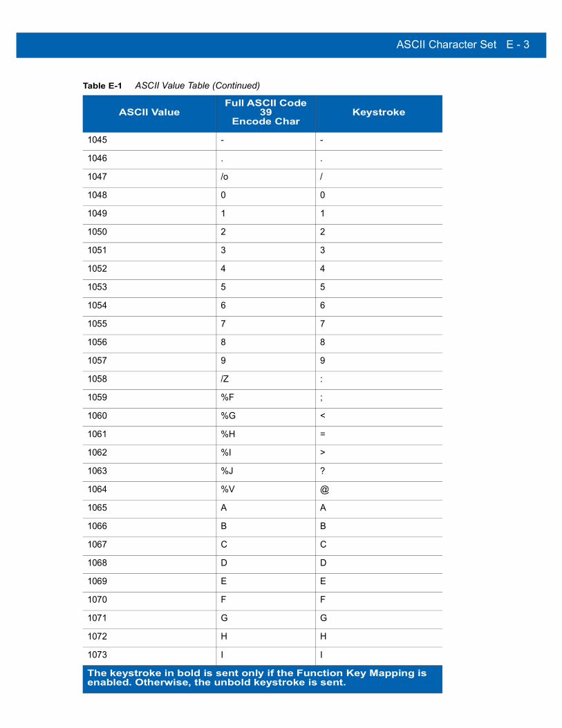
ASCII Character Set E - 3
1045 - -
1046 . .
1047 /o /
1048 0 0
1049 1 1
1050 2 2
1051 3 3
1052 4 4
1053 5 5
1054 6 6
1055 7 7
1056 8 8
1057 9 9
1058 /Z :
1059 %F ;
1060 %G <
1061 %H =
1062 %I >
1063 %J ?
1064 %V @
1065 A A
1066 B B
1067 C C
1068 D D
1069 E E
1070 F F
1071 G G
1072 H H
1073 I I
Table E-1 ASCII Value Table (Continued)
ASCII ValueFull ASCII Code
39 Encode Char
Keystroke
The keystroke in bold is sent only if the Function Key Mapping is enabled. Otherwise, the unbold keystroke is sent.

E - 4 DS457 Fixed Mount Imager Integration Guide
1074 J J
1075 K K
1076 L L
1077 M M
1078 N N
1079 O O
1080 P P
1081 Q Q
1082 R R
1083 S S
1084 T T
1085 U U
1086 V V
1087 W W
1088 X X
1089 Y Y
1090 Z Z
1091 %K [
1092 %L \
1093 %M ]
1094 %N ^
1095 %O _
1096 %W ‘
1097 +A a
1098 +B b
1099 +C c
1100 +D d
1101 +E e
1102 +F f
Table E-1 ASCII Value Table (Continued)
ASCII ValueFull ASCII Code
39 Encode Char
Keystroke
The keystroke in bold is sent only if the Function Key Mapping is enabled. Otherwise, the unbold keystroke is sent.

ASCII Character Set E - 5
1103 +G g
1104 +H h
1105 +I i
1106 +J j
1107 +K k
1108 +L l
1109 +M m
1110 +N n
1111 +O o
1112 +P p
1113 +Q q
1114 +R r
1115 +S s
1116 +T t
1117 +U u
1118 +V v
1119 +W w
1120 +X x
1121 +Y y
1122 +Z z
1123 %P {
1124 %Q I
1125 %R }
1126 %S ~
Table E-1 ASCII Value Table (Continued)
ASCII ValueFull ASCII Code
39 Encode Char
Keystroke
The keystroke in bold is sent only if the Function Key Mapping is enabled. Otherwise, the unbold keystroke is sent.
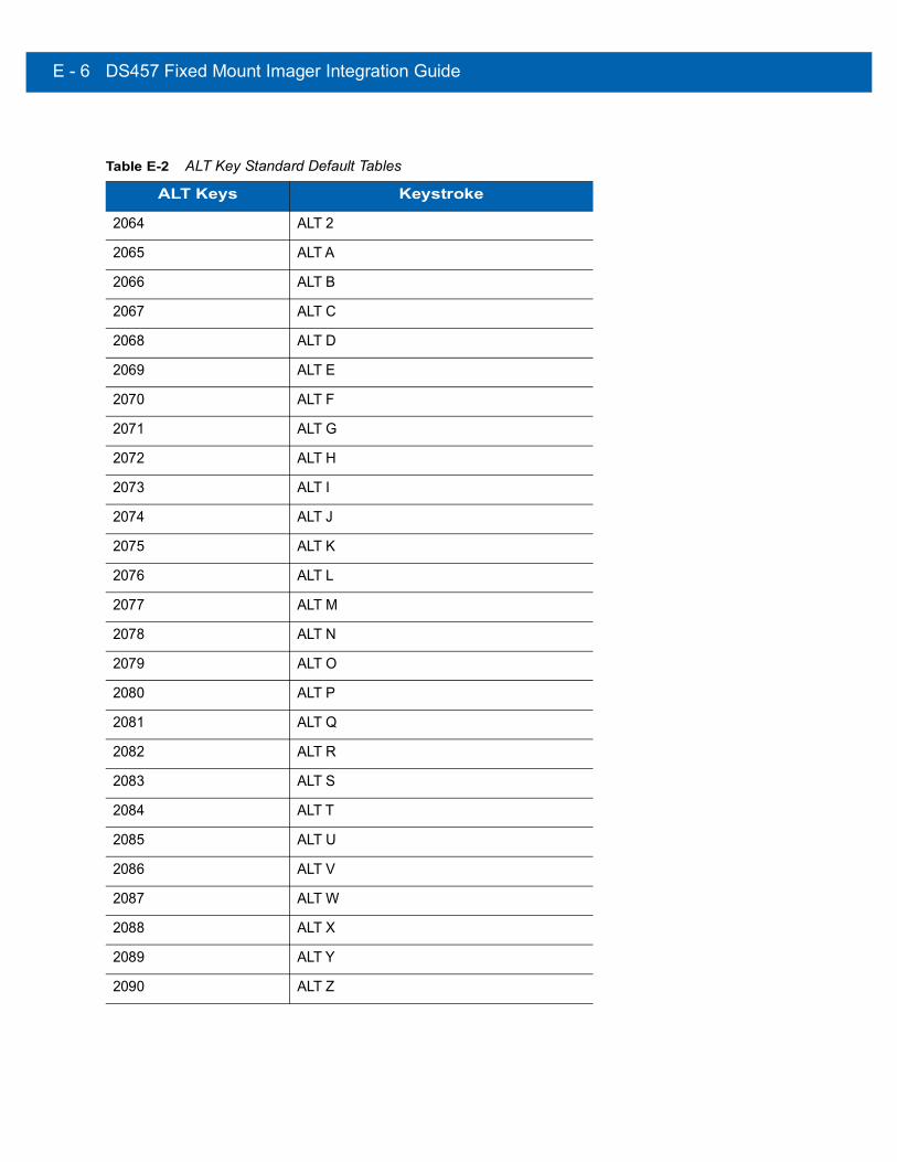
E - 6 DS457 Fixed Mount Imager Integration Guide
Table E-2 ALT Key Standard Default Tables
ALT Keys Keystroke
2064 ALT 2
2065 ALT A
2066 ALT B
2067 ALT C
2068 ALT D
2069 ALT E
2070 ALT F
2071 ALT G
2072 ALT H
2073 ALT I
2074 ALT J
2075 ALT K
2076 ALT L
2077 ALT M
2078 ALT N
2079 ALT O
2080 ALT P
2081 ALT Q
2082 ALT R
2083 ALT S
2084 ALT T
2085 ALT U
2086 ALT V
2087 ALT W
2088 ALT X
2089 ALT Y
2090 ALT Z
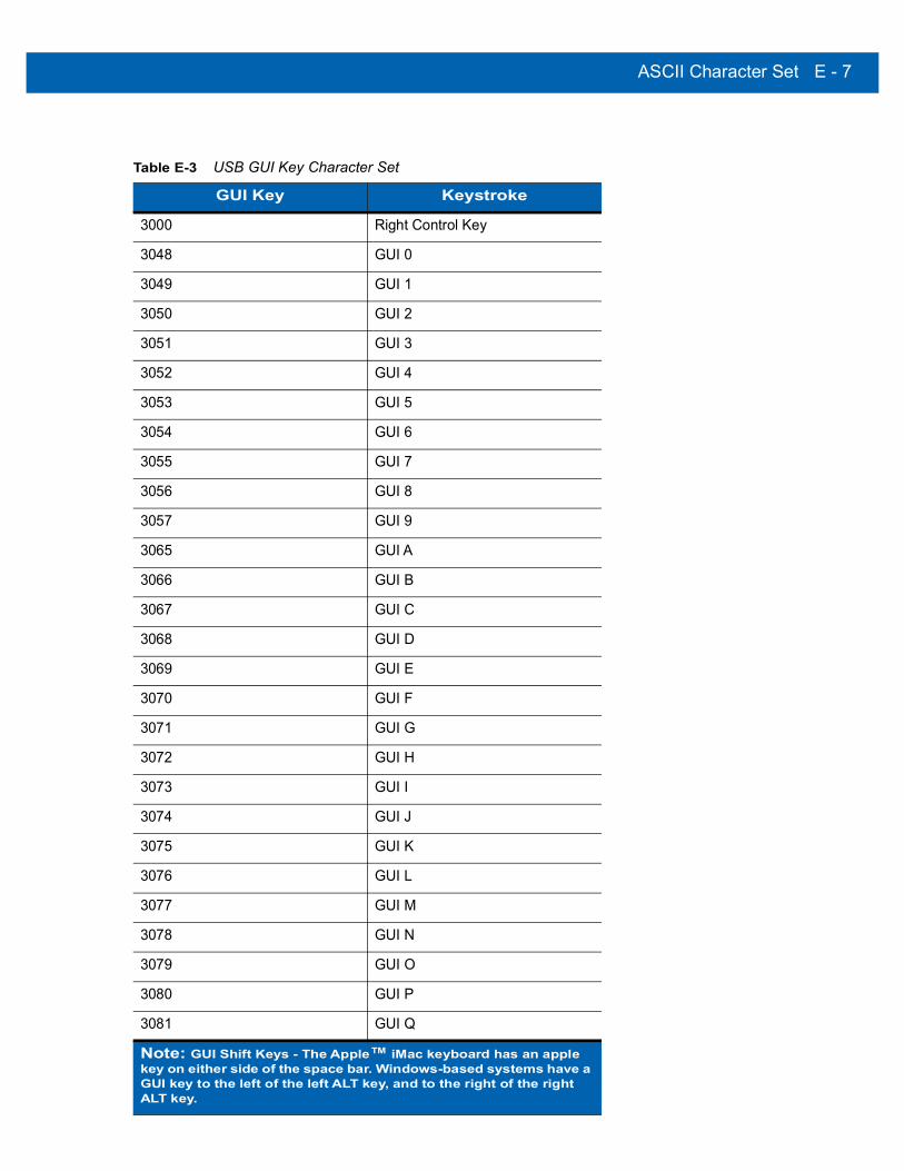
ASCII Character Set E - 7
Table E-3 USB GUI Key Character Set
GUI Key Keystroke
3000 Right Control Key
3048 GUI 0
3049 GUI 1
3050 GUI 2
3051 GUI 3
3052 GUI 4
3053 GUI 5
3054 GUI 6
3055 GUI 7
3056 GUI 8
3057 GUI 9
3065 GUI A
3066 GUI B
3067 GUI C
3068 GUI D
3069 GUI E
3070 GUI F
3071 GUI G
3072 GUI H
3073 GUI I
3074 GUI J
3075 GUI K
3076 GUI L
3077 GUI M
3078 GUI N
3079 GUI O
3080 GUI P
3081 GUI Q
Note: GUI Shift Keys - The Apple™ iMac keyboard has an apple key on either side of the space bar. Windows-based systems have a GUI key to the left of the left ALT key, and to the right of the right ALT key.

E - 8 DS457 Fixed Mount Imager Integration Guide
3082 GUI R
3083 GUI S
3084 GUI T
3085 GUI U
3086 GUI V
3087 GUI W
3088 GUI X
3089 GUI Y
3090 GUI Z
Table E-3 USB GUI Key Character Set (Continued)
GUI Key Keystroke
Note: GUI Shift Keys - The Apple™ iMac keyboard has an apple key on either side of the space bar. Windows-based systems have a GUI key to the left of the left ALT key, and to the right of the right ALT key.

ASCII Character Set E - 9
Table E-4 PF Key Standard Default Table
PF Keys Keystroke
4001 PF 1
4002 PF 2
4003 PF 3
4004 PF 4
4005 PF 5
4006 PF 6
4007 PF 7
4008 PF 8
4009 PF 9
4010 PF 10
4011 PF 11
4012 PF 12
4013 PF 13
4014 PF 14
4015 PF 15
4016 PF 16

E - 10 DS457 Fixed Mount Imager Integration Guide
Table E-5 F key Standard Default Table
F Keys Keystroke
5001 F 1
5002 F 2
5003 F 3
5004 F 4
5005 F 5
5006 F 6
5007 F 7
5008 F 8
5009 F 9
5010 F 10
5011 F 11
5012 F 12
5013 F 13
5014 F 14
5015 F 15
5016 F 16
5017 F 17
5018 F 18
5019 F 19
5020 F 20
5021 F 21
5022 F 22
5023 F 23
5024 F 24
Table E-6 Numeric Key Standard Default Table
Numeric Keypad Keystroke
6042 *
6043 +
6044 Undefined

ASCII Character Set E - 11
6045 -
6046 .
6047 /
6048 0
6049 1
6050 2
6051 3
6052 4
6053 5
6054 6
6055 7
6056 8
6057 9
6058 Enter
6059 Num Lock
Table E-6 Numeric Key Standard Default Table (Continued)
Numeric Keypad Keystroke

E - 12 DS457 Fixed Mount Imager Integration Guide
Table E-7 Extended Keypad Standard Default Table
Extended Keypad Keystroke
7001 Break
7002 Delete
7003 Pg Up
7004 End
7005 Pg Dn
7006 Pause
7007 Scroll Lock
7008 Backspace
7009 Tab
7010 Print Screen
7011 Insert
7012 Home
7013 Enter
7014 Escape
7015 Up Arrow
7016 Dn Arrow
7017 Left Arrow
7018 Right Arrow

INDEX
Numerics123Scan . . . . . . . . . . . . . . . . . . . . . . . . . . . . . . . . . 14-12D bar codes
aztec . . . . . . . . . . . . . . . . . . . . . . . . . . . . . . . . 12-90aztec inverse . . . . . . . . . . . . . . . . . . . . . . . . . 12-91code 128 emulation . . . . . . . . . . . . . . . . . . . . 12-84data matrix . . . . . . . . . . . . . . . . . . . . . . . . . . . 12-85data matrix inverse . . . . . . . . . . . . . . . . . . . . . 12-86maxicode . . . . . . . . . . . . . . . . . . . . . . . . . . . . 12-88microPDF417 . . . . . . . . . . . . . . . . . . . . . . . . . 12-83MicroQR . . . . . . . . . . . . . . . . . . . . . . . . . . . . . 12-90PDF417 . . . . . . . . . . . . . . . . . . . . . . . . . . . . . 12-83QR code . . . . . . . . . . . . . . . . . . . . . . . . . . . . . 12-88QR inverse . . . . . . . . . . . . . . . . . . . . . . . . . . . 12-89
Aaccessories . . . . . . . . . . . . . . . . . . . . . . . . . . . . . . 2-16adding window . . . . . . . . . . . . . . . . . . . . . . . . . . . 2-11ADF . . . . . . . . . . . . . . . . . . . . . . . . . . . . . . . . . . . . . 15-1advanced data formatting . . . . . . . . . . . . . . . . . . 15-1aiming . . . . . . . . . . . . . . . . . . . . . . . . . . . . . . . . . . . 3-1
control . . . . . . . . . . . . . . . . . . . . . . . . . . . . . . . . . 3-2LED spec . . . . . . . . . . . . . . . . . . . . . . . . . . . . . . 4-3
aiming optionsdecode aiming pattern . . . . . . . . . . . . . . . . . . . . 7-6snapshot aiming pattern . . . . . . . . . . . . . . . . . . 7-14snapshot mode timeout . . . . . . . . . . . . . . . . . . 7-14video view finder . . . . . . . . . . . . . . . . . . . . . . . . 7-32
aiming pattern . . . . . . . . . . . . . . . . . . . . . . . . . . . . 7-14enabling . . . . . . . . . . . . . . . . . . . . . . . . . . . . . . . 7-6orientation . . . . . . . . . . . . . . . . . . . . . . . . . . . . . . 3-3
aiming tips . . . . . . . . . . . . . . . . . . . . . . . . . . . . . . . . 3-3ambient light immunity . . . . . . . . . . . . . . . . . . . . . . 4-3anti-reflection coaters . . . . . . . . . . . . . . . . . . . . . 2-13ASCII values . . . . . . . . . . . . . . . . . . . . . . . . . . . . . . E-1
serial . . . . . . . . . . . . . . . . . . . . . . . . . . . . . . . . . 9-19USB . . . . . . . . . . . . . . . . . . . . . . . . . . . . . . . . . 10-18
assembling stand . . . . . . . . . . . . . . . . . . . . . . . . . . . 2-3autoexposure . . . . . . . . . . . . . . . . . . . . . . . . . 7-5, 7-12
Bbar codes
AAMVA field parsing . . . . . . . . . . . . . . . . . . . . . 13-6Australia post format . . . . . . . . . . . . . . . . . . . . 12-72autoexposure . . . . . . . . . . . . . . . . . . . . . . . 7-5, 7-12aztec . . . . . . . . . . . . . . . . . . . . . . . . . . . . . . . . 12-90aztec inverse . . . . . . . . . . . . . . . . . . . . . . . . . . 12-91beep after good decode . . . . . . . . . . . . . . . . . . . 6-8beeper tone . . . . . . . . . . . . . . . . . . . . . . . . . . . . . 6-9beeper volume . . . . . . . . . . . . . . . . . . . . . . . . . . 6-10bits per pixel . . . . . . . . . . . . . . . . . . . . . . 7-27, 7-30bookland EAN . . . . . . . . . . . . . . . . . . . . . . . . . 12-11bookland ISBN . . . . . . . . . . . . . . . . . . . . . . . . 12-24codabar start and stop characters . . . . . . . . . . 12-58code 128 emulation . . . . . . . . . . . . . . . . . . . . . 12-84code 128 security level . . . . . . . . . . . . . . . . . . 12-33code 39
transmit buffer . . . . . . . . . . . . . . . . . . . . . . 12-40code39 security level . . . . . . . . . . . . . . . . . . . . 12-42composite CC-A/B . . . . . . . . . . . . . . . . . . . . . . 12-79composite CC-C . . . . . . . . . . . . . . . . . . . . . . . 12-79composite TLC-39 . . . . . . . . . . . . . . . . . . . . . . 12-80continuous bar code read . . . . . . . . . . . . . . . . . 6-20continuous snapshot . . . . . . . . . . . . . . . . . . . . . 7-15coupon report . . . . . . . . . . . . . . . . . . . . . . . . . 12-26crop to address . . . . . . . . . . . . . . . . . . . . . . . . . 7-17data matrix . . . . . . . . . . . . . . . . . . . . . . . . . . . . 12-85data matrix inverse . . . . . . . . . . . . . . . . . . . . . 12-86data options . . . . . . . . . . . . . . . . . . . . . . . . . . . . 6-37
prefix/suffix values . . . . . . . . . . . . . . . . . . . 6-38transmit code ID character . . . . . . . . . . . . . 6-37

Index - 2 DS457 Fixed Mount Imager Integration Guide
decode aiming pattern . . . . . . . . . . . . . . . . . . . . 7-6decode session timeout . . . . . . . . . . . . . . . . . . 6-19discrete 2 of 5
lengths . . . . . . . . . . . . . . . . . . . . . . . . . . . 12-54driver’s license parsing . . . . . . . . . . . . . . . . . . . 13-1
set up . . . . . . . . . . . . . . . . . . . . . . . . . . . . . 13-3EAN-13/JAN-13 . . . . . . . . . . . . . . . . . . . . . . . 12-11EAN-8/JAN-8 . . . . . . . . . . . . . . . . . . . . . . . . . 12-10ecode mirror images . . . . . . . . . . . . . . . . . . . . 12-87event reporting
boot up event . . . . . . . . . . . . . . . . . . . . . . . 8-19decode event . . . . . . . . . . . . . . . . . . . . . . . 8-18parameter event . . . . . . . . . . . . . . . . . . . . . 8-19
exposure time . . . . . . . . . . . . . . . . . . . . . . . . . . 7-13field updates . . . . . . . . . . . . . . . . . . . . . . . . . . 13-22fixed gain . . . . . . . . . . . . . . . . . . . . . . . . . . . . . . 7-13flush macro buffer/abort macro PDF entry . . . 12-99GS1 databar limited security level . . . . . . . . . 12-77I 2 of 5 security level . . . . . . . . . . . . . . . . . . . . 12-52illumination . . . . . . . . . . . . . . . . . . . . . . . . .7-6, 7-12image brightness (target white) . . . . . . . . . . . . . 7-19image cropping . . . . . . . . . . . . . . . . . . . . . . . . . 7-16image enhancement . . . . . . . . . . . . . . . . . . . . . 7-22image file format . . . . . . . . . . . . . . . . . . . .7-20, 7-29image file meta data . . . . . . . . . . . . . . . . . . . . . 7-22image resolution . . . . . . . . . . . . . . . . . . . . . . . . 7-18imager
default table . . . . . . . . . . . . . . . . . . . . . . . . . 7-2interleaved 2 of 5 . . . . . . . . . . . . . . . . . . . . . . 12-48
convert to EAN-13 . . . . . . . 12-33, 12-51, 12-52lengths . . . . . . . . . . . . . . . . . . . . . .12-49, 12-50
inverse 1D . . . . . . . . . . . . . . . . . . . . . . . . . . . . 12-67JPEG image options . . . . . . . . . . . . . . . . . . . . . 7-20JPEG quality and size . . . . . . . . . . . . . . . . . . . . 7-21low light enhancement . . . . . . . . . . . . . . . . . . . . 7-8maxicode . . . . . . . . . . . . . . . . . . . . . . . . . . . . . 12-88microPDF417 . . . . . . . . . . . . . . . . . . . . . . . . . 12-83MicroQR . . . . . . . . . . . . . . . . . . . . . . . . . . . . . 12-90mirrored image . . . . . . . . . . . . . . . . . . . . . . . . . 6-21miscellaneous
scan data options . . . . . . . . . . . . . . . . . . . . 6-39transmit no read msg . . . . . . . . . . . . . . . . . 6-41
mobile phone/display mode . . . . . . . . . . . . . . . 6-22multicode expression . . . . . . . . . . . . . . . . . . . . 6-25multicode expression examples . . . . . . . . . . . . 6-27multicode expression via SSI . . . . . . . . . . . . . . 6-31multicode mode . . . . . . . . . . . . . . . . . . . . . . . . . 6-24numeric bar codes . . . . . . . . . . . . . . . . . . . . . . . D-3OCR
bright illumination . . . . . . . . . . . . . . . . . . . 11-15check digit . . . . . . . . . . . . . . . . . . . . . . . . . 11-25check digit multiplier . . . . . . . . . . . . . . . . . 11-26check digit validation . . . . . . . . . . . . . . . . 11-27default table . . . . . . . . . . . . . . . . . . . . . . . . 11-2
inverse OCR . . . . . . . . . . . . . . . . . . . . . . . 11-31lines . . . . . . . . . . . . . . . . . . . . . . . . . . . . . . 11-12maximum characters . . . . . . . . . . . . . . . . . 11-13MICR E13B . . . . . . . . . . . . . . . . . . . . . . . . . 11-9minimum chararacter . . . . . . . . . . . . . . . . . 11-13OCR-A . . . . . . . . . . . . . . . . . . . . . . . . . . . . . 11-3OCR-A variant . . . . . . . . . . . . . . . . . . . . . . . 11-3OCR-B . . . . . . . . . . . . . . . . . . . . . . . . . . . . . 11-5OCR-B variant . . . . . . . . . . . . . . . . . . . . . . . 11-6orientation . . . . . . . . . . . . . . . . . . . . . . . . . 11-10parameters . . . . . . . . . . . . . . . . . . . . . . . . . 11-3quiet zone . . . . . . . . . . . . . . . . . . . . . . . . . 11-14security level . . . . . . . . . . . . . . . . . . . . . . . 11-13subset . . . . . . . . . . . . . . . . . . . . . . . . . . . . 11-14template . . . . . . . . . . . . . . . . . . . . . . . . . . . 11-16US currency serial number . . . . . . . . . . . . 11-10
operational mode . . . . . . . . . . . . . . . . . . . . . . . . . 7-4parameter scanning . . . . . . . . . . . . . . . . . . . . . . . 6-6parser version ID . . . . . . . . . . . . . . . . . . . . . . . 13-15parsing ADF example . . . . . . . . . . . . . . . . . . . 13-20parsing rule example . . . . . . . . . . . . . . . . . . . . 13-16PDF prioritization . . . . . . . . . . . . . . . . . . . . . . . . 6-23PDF prioritization timeout . . . . . . . . . . . . . . . . . . 6-23PDF417 . . . . . . . . . . . . . . . . . . . . . . . . . . . . . . 12-83picklist mode . . . . . . . . . . . . . . . . . . . . . . . . . . . 6-19postal . . . . . . . . . . . . . . . . . . . . . . . . . . . . . . . . 12-68power mode . . . . . . . . . . . . . . . . . . . . . . . . . . . . 6-17prefix/suffix values . . . . . . . . . . . . . . . . . . . . . . . 6-38presentation mode field of view . . . . . . . . . . . . . . 7-9presentation performance mode . . . . . . . . . . . . 6-12presentation snapshot . . . . . . . . . . . . . . . . . . . . 7-15QR code . . . . . . . . . . . . . . . . . . . . . . . . . . . . . . 12-88QR inverse . . . . . . . . . . . . . . . . . . . . . . . . . . . . 12-89RS-232
beep on bel . . . . . . . . . . . . . . . . . . . . . . . . 10-17serial
baud rate . . . . . . . . . . . . . . . . . . . . . . . . . . . . 9-7beep on bel . . . . . . . . . . . . . . . . . . . . . . . . . 9-16check receive errors . . . . . . . . . . . . . . . . . . 9-10data bits . . . . . . . . . . . . . . . . . . . . . . . . . . . . . 9-9default table . . . . . . . . . . . . . . . . . . . . . . . . . . 9-2hardware handshaking . . . . . . . . . . . 9-11, 9-12host serial response time-out . . . . . . . . . . . 9-15host types . . . . . . . . . . . . . . . . . . . . . . . . . . . 9-5intercharacter delay . . . . . . . . . . . . . . . . . . . 9-17parity . . . . . . . . . . . . . . . . . . . . . . . . . . . . . . . 9-9RTS line state . . . . . . . . . . . . . . . . . . . . . . . 9-16software handshaking . . . . . . . . . . . . . . . . . 9-13stop bit select . . . . . . . . . . . . . . . . . . . . . . . 9-16
set defaults . . . . . . . . . . . . . . . . . . . . . . . 6-5, 13-23signature capture . . . . . . . . . . . . . . . . . . . . . . . . 7-28signature capture height . . . . . . . . . . . . . . . . . . 7-31signature capture JPEG quality . . . . . . . . . . . . . 7-31signature capture width . . . . . . . . . . . . . . . . . . . 7-30
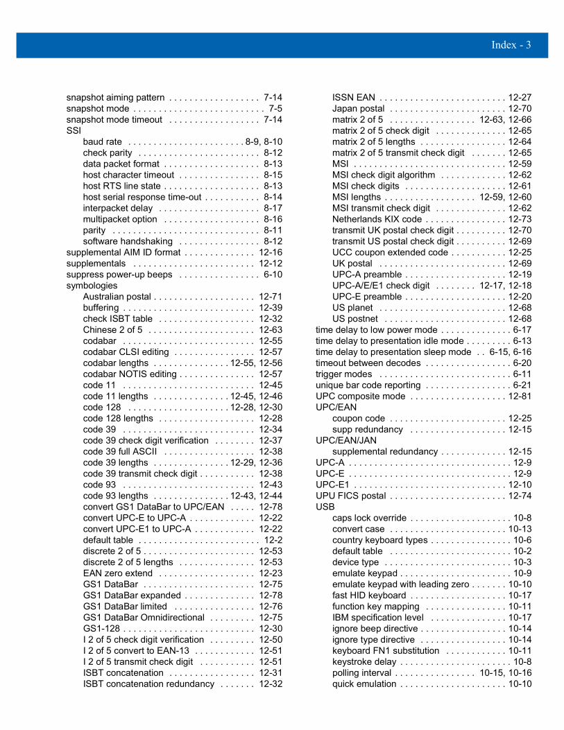
Index - 3
snapshot aiming pattern . . . . . . . . . . . . . . . . . . 7-14snapshot mode . . . . . . . . . . . . . . . . . . . . . . . . . . 7-5snapshot mode timeout . . . . . . . . . . . . . . . . . . 7-14SSI
baud rate . . . . . . . . . . . . . . . . . . . . . . . 8-9, 8-10check parity . . . . . . . . . . . . . . . . . . . . . . . . 8-12data packet format . . . . . . . . . . . . . . . . . . . 8-13host character timeout . . . . . . . . . . . . . . . . 8-15host RTS line state . . . . . . . . . . . . . . . . . . . 8-13host serial response time-out . . . . . . . . . . . 8-14interpacket delay . . . . . . . . . . . . . . . . . . . . 8-17multipacket option . . . . . . . . . . . . . . . . . . . 8-16parity . . . . . . . . . . . . . . . . . . . . . . . . . . . . . 8-11software handshaking . . . . . . . . . . . . . . . . 8-12
supplemental AIM ID format . . . . . . . . . . . . . . 12-16supplementals . . . . . . . . . . . . . . . . . . . . . . . . 12-12suppress power-up beeps . . . . . . . . . . . . . . . . 6-10symbologies
Australian postal . . . . . . . . . . . . . . . . . . . . 12-71buffering . . . . . . . . . . . . . . . . . . . . . . . . . . 12-39check ISBT table . . . . . . . . . . . . . . . . . . . 12-32Chinese 2 of 5 . . . . . . . . . . . . . . . . . . . . . 12-63codabar . . . . . . . . . . . . . . . . . . . . . . . . . . 12-55codabar CLSI editing . . . . . . . . . . . . . . . . 12-57codabar lengths . . . . . . . . . . . . . . . 12-55, 12-56codabar NOTIS editing . . . . . . . . . . . . . . . 12-57code 11 . . . . . . . . . . . . . . . . . . . . . . . . . . 12-45code 11 lengths . . . . . . . . . . . . . . . 12-45, 12-46code 128 . . . . . . . . . . . . . . . . . . . . 12-28, 12-30code 128 lengths . . . . . . . . . . . . . . . . . . . 12-28code 39 . . . . . . . . . . . . . . . . . . . . . . . . . . 12-34code 39 check digit verification . . . . . . . . 12-37code 39 full ASCII . . . . . . . . . . . . . . . . . . 12-38code 39 lengths . . . . . . . . . . . . . . . 12-29, 12-36code 39 transmit check digit . . . . . . . . . . . 12-38code 93 . . . . . . . . . . . . . . . . . . . . . . . . . . 12-43code 93 lengths . . . . . . . . . . . . . . . 12-43, 12-44convert GS1 DataBar to UPC/EAN . . . . . 12-78convert UPC-E to UPC-A . . . . . . . . . . . . . 12-22convert UPC-E1 to UPC-A . . . . . . . . . . . . 12-22default table . . . . . . . . . . . . . . . . . . . . . . . . 12-2discrete 2 of 5 . . . . . . . . . . . . . . . . . . . . . . 12-53discrete 2 of 5 lengths . . . . . . . . . . . . . . . 12-53EAN zero extend . . . . . . . . . . . . . . . . . . . 12-23GS1 DataBar . . . . . . . . . . . . . . . . . . . . . . 12-75GS1 DataBar expanded . . . . . . . . . . . . . . 12-78GS1 DataBar limited . . . . . . . . . . . . . . . . 12-76GS1 DataBar Omnidirectional . . . . . . . . . 12-75GS1-128 . . . . . . . . . . . . . . . . . . . . . . . . . . 12-30I 2 of 5 check digit verification . . . . . . . . . 12-50I 2 of 5 convert to EAN-13 . . . . . . . . . . . . 12-51I 2 of 5 transmit check digit . . . . . . . . . . . 12-51ISBT concatenation . . . . . . . . . . . . . . . . . 12-31ISBT concatenation redundancy . . . . . . . 12-32
ISSN EAN . . . . . . . . . . . . . . . . . . . . . . . . . 12-27Japan postal . . . . . . . . . . . . . . . . . . . . . . . 12-70matrix 2 of 5 . . . . . . . . . . . . . . . . . 12-63, 12-66matrix 2 of 5 check digit . . . . . . . . . . . . . . 12-65matrix 2 of 5 lengths . . . . . . . . . . . . . . . . . 12-64matrix 2 of 5 transmit check digit . . . . . . . 12-65MSI . . . . . . . . . . . . . . . . . . . . . . . . . . . . . . 12-59MSI check digit algorithm . . . . . . . . . . . . . 12-62MSI check digits . . . . . . . . . . . . . . . . . . . . 12-61MSI lengths . . . . . . . . . . . . . . . . . . 12-59, 12-60MSI transmit check digit . . . . . . . . . . . . . . 12-62Netherlands KIX code . . . . . . . . . . . . . . . . 12-73transmit UK postal check digit . . . . . . . . . . 12-70transmit US postal check digit . . . . . . . . . . 12-69UCC coupon extended code . . . . . . . . . . . 12-25UK postal . . . . . . . . . . . . . . . . . . . . . . . . . 12-69UPC-A preamble . . . . . . . . . . . . . . . . . . . . 12-19UPC-A/E/E1 check digit . . . . . . . . 12-17, 12-18UPC-E preamble . . . . . . . . . . . . . . . . . . . . 12-20US planet . . . . . . . . . . . . . . . . . . . . . . . . . 12-68US postnet . . . . . . . . . . . . . . . . . . . . . . . . 12-68
time delay to low power mode . . . . . . . . . . . . . . 6-17time delay to presentation idle mode . . . . . . . . . 6-13time delay to presentation sleep mode . . 6-15, 6-16timeout between decodes . . . . . . . . . . . . . . . . . 6-20trigger modes . . . . . . . . . . . . . . . . . . . . . . . . . . 6-11unique bar code reporting . . . . . . . . . . . . . . . . . 6-21UPC composite mode . . . . . . . . . . . . . . . . . . . 12-81UPC/EAN
coupon code . . . . . . . . . . . . . . . . . . . . . . . 12-25supp redundancy . . . . . . . . . . . . . . . . . . . 12-15
UPC/EAN/JANsupplemental redundancy . . . . . . . . . . . . . 12-15
UPC-A . . . . . . . . . . . . . . . . . . . . . . . . . . . . . . . . 12-9UPC-E . . . . . . . . . . . . . . . . . . . . . . . . . . . . . . . . 12-9UPC-E1 . . . . . . . . . . . . . . . . . . . . . . . . . . . . . . 12-10UPU FICS postal . . . . . . . . . . . . . . . . . . . . . . . 12-74USB
caps lock override . . . . . . . . . . . . . . . . . . . . 10-8convert case . . . . . . . . . . . . . . . . . . . . . . . 10-13country keyboard types . . . . . . . . . . . . . . . . 10-6default table . . . . . . . . . . . . . . . . . . . . . . . . 10-2device type . . . . . . . . . . . . . . . . . . . . . . . . . 10-3emulate keypad . . . . . . . . . . . . . . . . . . . . . . 10-9emulate keypad with leading zero . . . . . . . 10-10fast HID keyboard . . . . . . . . . . . . . . . . . . . 10-17function key mapping . . . . . . . . . . . . . . . . 10-11IBM specification level . . . . . . . . . . . . . . . 10-17ignore beep directive . . . . . . . . . . . . . . . . . 10-14ignore type directive . . . . . . . . . . . . . . . . . 10-14keyboard FN1 substitution . . . . . . . . . . . . 10-11keystroke delay . . . . . . . . . . . . . . . . . . . . . . 10-8polling interval . . . . . . . . . . . . . . . . 10-15, 10-16quick emulation . . . . . . . . . . . . . . . . . . . . . 10-10

Index - 4 DS457 Fixed Mount Imager Integration Guide
simulated caps lock . . . . . . . . . . . . . . . . . 10-12SNAPI handshaking . . . . . . . . . . . . . . . . . . 10-5static CDC . . . . . . . . . . . . . . . . . . . . . . . . 10-13unknown characters . . . . . . . . . . . . . . . . . . 10-9
user parameter pass through . . . . . . . . . . . . . . . 6-7USPS 4CB/One Code/Intelligent Mail . . . . . . . 12-74validate concatenated parameter bar codes . . . 6-22video frame size . . . . . . . . . . . . . . . . . . . . . . . . 7-33video mode . . . . . . . . . . . . . . . . . . . . . . . . . . . . . 7-5video mode format selector . . . . . . . . . . . . . . . . 7-31video view finder . . . . . . . . . . . . . . . . . . . . . . . . 7-32wand emulation
default table . . . . . . . . . . . . . . . . . . . . . . . . . 8-8beeper . . . . . . . . . . . . . . . . . . . . . . . . . . . . . . . . . . . . 3-4
suppress power-up beeps . . . . . . . . . . . . . . . . . 6-10block diagram . . . . . . . . . . . . . . . . . . . . . . . . . . . . . 1-3
component descriptions . . . . . . . . . . . . . . . . . . . 1-4
Cchapter descriptions . . . . . . . . . . . . . . . . . . . . . . . . . xvcharacter sets . . . . . . . . . . . . . . . . . . . . . . . . . . . . . E-1
serial . . . . . . . . . . . . . . . . . . . . . . . . . . . . . . . . . 9-19USB . . . . . . . . . . . . . . . . . . . . . . . . . . . . . . . . . 10-18
Chinese 2 of 5 . . . . . . . . . . . . . . . . . . . . . . . . . . . 12-63codabar bar codes
CLSI editing . . . . . . . . . . . . . . . . . . . . . . . . . . 12-57codabar . . . . . . . . . . . . . . . . . . . . . . . . . . . . . . 12-55lengths . . . . . . . . . . . . . . . . . . . . . . . . .12-55, 12-56NOTIS editing . . . . . . . . . . . . . . . . . . . . . . . . . 12-57start and stop characters . . . . . . . . . . . . . . . . 12-58
code 11 bar codescode 11 . . . . . . . . . . . . . . . . . . . . . . . . . . . . . . 12-45lengths . . . . . . . . . . . . . . . . . . . . . . . . .12-45, 12-46
code 128 bar codescheck ISBT table . . . . . . . . . . . . . . . . . . . . . . . 12-32code 128 . . . . . . . . . . . . . . . . . . . . . . . .12-28, 12-30GS1-128 . . . . . . . . . . . . . . . . . . . . . . . . . . . . . 12-30ISBT concatenation . . . . . . . . . . . . . . . . . . . . . 12-31ISBT concatenation redundancy . . . . . . . . . . . 12-32lengths . . . . . . . . . . . . . . . . . . . . . . . . . . . . . . 12-28security level . . . . . . . . . . . . . . . . . . . . . . . . . . 12-33
code 128 emulation bar codes . . . . . . . . . . . . . . 12-84code 39 bar codes
buffering . . . . . . . . . . . . . . . . . . . . . . . . . . . . . 12-39check digit verification . . . . . . . . . . . . . . . . . . . 12-37code 39 . . . . . . . . . . . . . . . . . . . . . . . . . . . . . . 12-34full ASCII . . . . . . . . . . . . . . . . . . . . . . . . . . . . . 12-38lengths . . . . . . . . . . . . . . . . . . . . . . . . .12-29, 12-36security level . . . . . . . . . . . . . . . . . . . . . . . . . . 12-42transmit check digit . . . . . . . . . . . . . . . . . . . . . 12-38
code 93 bar codescode 93 . . . . . . . . . . . . . . . . . . . . . . . . . . . . . . 12-43lengths . . . . . . . . . . . . . . . . . . . . . . . . .12-43, 12-44
code identifiersAIM code IDs . . . . . . . . . . . . . . . . . . . . . . . . . . . .B-1
composite bar codescomposite CC-A/B . . . . . . . . . . . . . . . . . . . . . . 12-79composite CC-C . . . . . . . . . . . . . . . . . . . . . . . . 12-79composite TLC-39 . . . . . . . . . . . . . . . . . . . . . . 12-80UPC composite mode . . . . . . . . . . . . . . . . . . . 12-81
configurations . . . . . . . . . . . . . . . . . . . . . . . . . . . . . .xvconventions
notational . . . . . . . . . . . . . . . . . . . . . . . . . . . . . . . xvicropping . . . . . . . . . . . . . . . . . . . . . . . . . . . . 7-16, 7-17
Ddata capture . . . . . . . . . . . . . . . . . . . . . . . . . . . . . . . 3-3data matrix bar codes . . . . . . . . . . . . . . . . . . . . . 12-85decode distances
DP focus . . . . . . . . . . . . . . . . . . . . . . . . . . . . . . 4-11HD focus . . . . . . . . . . . . . . . . . . . . . . . . . . . . . . 4-11SR focus . . . . . . . . . . . . . . . . . . . . . . . . . . . . . . . 4-8
decode mode . . . . . . . . . . . . . . . . . . . . . . . . . . . . . . 7-4decode zones . . . . . . . . . . . . . . . . . . . . . . . . . . . . . . 4-6
DP focus . . . . . . . . . . . . . . . . . . . . . . . . . . . . . . . 4-9HD focus . . . . . . . . . . . . . . . . . . . . . . . . . . . . . . . 4-9SR/DL focus . . . . . . . . . . . . . . . . . . . . . . . . . . . . . 4-6
default parametersOCR . . . . . . . . . . . . . . . . . . . . . . . . . . . . . . . . . . 11-2serial . . . . . . . . . . . . . . . . . . . . . . . . . . . . . . . . . . 9-2standard default table . . . . . . . . . . . . . . . . . . . . .A-1symbologies . . . . . . . . . . . . . . . . . . . . . . . . . . . . 12-2USB . . . . . . . . . . . . . . . . . . . . . . . . . . . . . . . . . . 10-2user preferences . . . . . . . . . . . . . . . . . . . . . 6-3, 7-2wand emulation . . . . . . . . . . . . . . . . . . . . . . . . . . 8-8
dimensions . . . . . . . . . . . . . . . . . . . . . . . . . . . . 4-2, 4-4direct part marking . . . . . . . . . . . . . . . . . . . . . . 1-2, 3-3discrete 2 of 5 bar codes
discrete 2 of 5 . . . . . . . . . . . . . . . . . . . . . . . . . 12-53lengths . . . . . . . . . . . . . . . . . . . . . . . . . . . . . . . 12-53
DP focus decode distances . . . . . . . . . . . . . . . . . . 4-11DPM . . . . . . . . . . . . . . . . . . . . . . . . . . . . . . . . . . 1-2, 3-3driver’s license parsing . . . . . . . . . . . . . . . . . . . . . 13-1
AAMVA field bar codes . . . . . . . . . . . . . . . . . . . 13-6bar codes . . . . . . . . . . . . . . . . . . . . . . . . . . . . . . 13-1embedded . . . . . . . . . . . . . . . . . . . . . . . . . . . . . 13-2embedded ADF example . . . . . . . . . . . . . . . . . 13-20field bar codes . . . . . . . . . . . . . . . . . . . . . . . . . . 13-3field updates . . . . . . . . . . . . . . . . . . . . . . . . . . 13-22rule example . . . . . . . . . . . . . . . . . . . . . . . . . . 13-16send control characters . . . . . . . . . . . . . . . . . . 13-23send keyboard characters . . . . . . . . . . . . . . . . 13-28set defaults . . . . . . . . . . . . . . . . . . . . . . . . . . . 13-23version ID . . . . . . . . . . . . . . . . . . . . . . . . . . . . . 13-15
drop specification . . . . . . . . . . . . . . . . . . . . . . . . . . 4-3

Index - 5
Eelectrical interface . . . . . . . . . . . . . . . . . . . . . . . . . 4-1engine . . . . . . . . . . . . . . . . . . . . . . . . . . . . . . . . . . . 1-4
theory of operation . . . . . . . . . . . . . . . . . . . . . . . 1-2escape characters . . . . . . . . . . . . . . . . . . . . . . . . 12-98exit window
diagram . . . . . . . . . . . . . . . . . . . . . . . . . . . . . . . 2-14properties . . . . . . . . . . . . . . . . . . . . . . . . . . . . . 2-15
exposure optionsautoexposure . . . . . . . . . . . . . . . . . . . . . . . 7-5, 7-12exposure time . . . . . . . . . . . . . . . . . . . . . . . . . . 7-13fixed gain . . . . . . . . . . . . . . . . . . . . . . . . . . . . . 7-13illumination . . . . . . . . . . . . . . . . . . . . . . . . . 7-6, 7-12low light enhancement . . . . . . . . . . . . . . . . . . . . 7-8presentation mode field of view . . . . . . . . . . . . . 7-9
exposure time . . . . . . . . . . . . . . . . . . . . . . . . . . . . 7-13
Ffield of view specification . . . . . . . . . . . . . . . . . . . 4-3fixed gain . . . . . . . . . . . . . . . . . . . . . . . . . . . . . . . . 7-13focal positions
distance from imager . . . . . . . . . . . . . . . . . . . . . 4-3
Ggain
fixed . . . . . . . . . . . . . . . . . . . . . . . . . . . . . . . . . 7-13GS1 DataBar . . . . . . . . . . . . . . . . . . . . . . . . . . . . 12-75
convert GS1 DataBar to UPC/EAN . . . . . . . . 12-78GS1 DataBar expanded . . . . . . . . . . . . . . . . . 12-78GS1 DataBar limited . . . . . . . . . . . . . . . . . . . . 12-76GS1 DataBar Omnidirectional . . . . . . . . . . . . 12-75
HHD focus decode distances . . . . . . . . . . . . . . . . . 4-11host types
serial . . . . . . . . . . . . . . . . . . . . . . . . . . . . . . . . . . 9-5humidity specification . . . . . . . . . . . . . . . . . . . . . . 4-3
Iillumination . . . . . . . . . . . . . . . . . . . . . . . . . . . 7-6, 7-12
element . . . . . . . . . . . . . . . . . . . . . . . . . . . . . . . . 4-3illumination system . . . . . . . . . . . . . . . . . . . . . . . . 3-2image brightness (target white) . . . . . . . . . . . . . . 7-19image cropping . . . . . . . . . . . . . . . . . . . . . . . 7-16, 7-17image enhancement . . . . . . . . . . . . . . . . . . . . . . . 7-22image options
bits per pixel . . . . . . . . . . . . . . . . . . . . . . . 7-27, 7-30cropping . . . . . . . . . . . . . . . . . . . . . . . . . . 7-16, 7-17file formats . . . . . . . . . . . . . . . . . . . . . . . . 7-20, 7-29
image brightness (target white) . . . . . . . . . . . . . 7-19image enhancement . . . . . . . . . . . . . . . . . . . . . 7-22image resolution . . . . . . . . . . . . . . . . . . . . . . . . 7-18JPEG . . . . . . . . . . . . . . . . . . . . . . . . . . . . . . . . . 7-20JPEG size/quality . . . . . . . . . . . . . . . . . . . . . . . 7-21video frame size . . . . . . . . . . . . . . . . . . . . . . . . 7-33
image resolution . . . . . . . . . . . . . . . . . . . . . . . . . . 7-18imager
defaults . . . . . . . . . . . . . . . . . . . . . . . . . . . . . . . . 7-2imager overview . . . . . . . . . . . . . . . . . . . . . . . . . . . . 1-1imaging engine . . . . . . . . . . . . . . . . . . . . . . . . . . . . . 1-4information, service . . . . . . . . . . . . . . . . . . . . . . . . . xviiinstallation
connecting . . . . . . . . . . . . . . . . . . . . . . . . . . . . . . 2-8location . . . . . . . . . . . . . . . . . . . . . . . . . . . . . . . 2-10mechanical drawing . . . . . . . . . . . . . . . . . . . . . . . 4-2mounting . . . . . . . . . . . . . . . . . . . . . . . . . . . . . . . 2-2mounting imager on stand . . . . . . . . . . . 2-3, 2-5, 2-7mounting stand . . . . . . . . . . . . . . . . . . . . . . . . . . 2-4stand . . . . . . . . . . . . . . . . . . . . . . . . . . . . . . . . . . 2-3
interface pin-outs . . . . . . . . . . . . . . . . . . . . . . . . . . . 4-1interleaved 2 of 5 bar codes
check digit verification . . . . . . . . . . . . . . . . . . . 12-50convert to EAN-13 . . . . . . . . . . . . . . . . . . . . . . 12-51security level . . . . . . . . . . . . . . . . . . . . . . . . . . 12-52transmit check digit . . . . . . . . . . . . . . . . . . . . . 12-51
JJPEG image options . . . . . . . . . . . . . . . . . . . . . . . 7-20
size/quality . . . . . . . . . . . . . . . . . . . . . . . . . . . . . 7-21
Llaser . . . . . . . . . . . . . . . . . . . . . . . . . . . . . . . . . . . . . 3-1LED . . . . . . . . . . . . . . . . . . . . . . . . . . . . . . . . . . . . . . 3-2
decode . . . . . . . . . . . . . . . . . . . . . . . . . . . . . . . . . 3-4low light enhancement . . . . . . . . . . . . . . . . . . . . . . 7-8
Mmacro PDF . . . . . . . . . . . . . . . . . . . . . . . . . . . . . . 12-96
buffer all symbols . . . . . . . . . . . . . . . . . . . . . . 12-97escape characters . . . . . . . . . . . . . . . . . . . . . . 12-98flush buffer/abort PDF entry . . . . . . . . . . . . . . 12-99transmit any symbol in set . . . . . . . . . . . . . . . . 12-97transmit user-selected fields . . . . . . . . . . . . . . 12-98transmit/decode mode symbols . . . . . . . . . . . . 12-97
maintenance . . . . . . . . . . . . . . . . . . . . . . . . . . . . . . . 5-1matrix 2 of 5 . . . . . . . . . . . . . . . . . . . . . . . 12-63, 12-66matrix 2 of 5 check digit . . . . . . . . . . . . . . . . . . . 12-65matrix 2 of 5 lengths . . . . . . . . . . . . . . . . . . . . . . 12-64matrix 2 of 5 transmit check digit . . . . . . . . . . . . 12-65maxicode bar codes . . . . . . . . . . . . . . . . . . . . . . 12-88

Index - 6 DS457 Fixed Mount Imager Integration Guide
mechanical drawing . . . . . . . . . . . . . . . . . . . . . . . . 4-2microPDF417 bar codes . . . . . . . . . . . . . . . . . . . 12-83microprocessor . . . . . . . . . . . . . . . . . . . . . . . . . . . . 1-5modes of operation . . . . . . . . . . . . . . . . . . . . . . . . . 3-5mounting . . . . . . . . . . . . . . . . . . . . . . . . . . . . . . . . . 2-2
dimensions . . . . . . . . . . . . . . . . . . . . . . . . . . . . . 2-2imager on stand . . . . . . . . . . . . . . . . . . 2-3, 2-5, 2-7stand . . . . . . . . . . . . . . . . . . . . . . . . . . . . . . . . . . 2-4
MSI bar codescheck digit algorithm . . . . . . . . . . . . . . . . . . . . 12-62check digits . . . . . . . . . . . . . . . . . . . . . . . . . . . 12-61lengths . . . . . . . . . . . . . . . . . . . . . . . . .12-59, 12-60MSI . . . . . . . . . . . . . . . . . . . . . . . . . . . . . . . . . 12-59transmit check digit . . . . . . . . . . . . . . . . . . . . . 12-62
multicode modeexpression examples . . . . . . . . . . . . . . . . . . . . 6-27multicode expression . . . . . . . . . . . . . . . . . . . . 6-25setting . . . . . . . . . . . . . . . . . . . . . . . . . . . . . . . . 6-24setting expression via SSI . . . . . . . . . . . . . . . . . 6-31troubleshooting . . . . . . . . . . . . . . . . . . . . . . . . . 6-35
Nnotational conventions . . . . . . . . . . . . . . . . . . . . . . .xvi
OOCR
default parameters . . . . . . . . . . . . . . . . . . . . . . 11-2parameters . . . . . . . . . . . . . . . . . . . . . . . . . . . . 11-3
operating modes . . . . . . . . . . . . . . . . . . . . . . . . . . . 3-5operational mode . . . . . . . . . . . . . . . . . . . . . . . . . . . 7-4
decode mode . . . . . . . . . . . . . . . . . . . . . . . . . . . 7-4snapshot mode . . . . . . . . . . . . . . . . . . . . . . . . . . 7-4video mode . . . . . . . . . . . . . . . . . . . . . . . . . . . . . 7-5
opticalpath and exit window diagram . . . . . . . . . . . . . 2-14resolution . . . . . . . . . . . . . . . . . . . . . . . . . . . . . . 4-3
overviewimager . . . . . . . . . . . . . . . . . . . . . . . . . . . . . . . . . 1-1
PPDF417 bar codes . . . . . . . . . . . . . . . . . . . . . . . . 12-83
PDF prioritization . . . . . . . . . . . . . . . . . . . . . . . 6-23pitch . . . . . . . . . . . . . . . . . . . . . . . . . . . . . . . . . . . . . 4-3postal codes . . . . . . . . . . . . . . . . . . . . . . . . . . . . . 12-68
Australia post format . . . . . . . . . . . . . . . . . . . . 12-72Australian postal . . . . . . . . . . . . . . . . . . . . . . . 12-71Japan postal . . . . . . . . . . . . . . . . . . . . . . . . . . 12-70Netherlands KIX code . . . . . . . . . . . . . . . . . . . 12-73transmit UK postal check digit . . . . . . . . . . . . . 12-70transmit US postal check digit . . . . . . . . . . . . . 12-69UK postal . . . . . . . . . . . . . . . . . . . . . . . . . . . . 12-69
UPU FICS postal . . . . . . . . . . . . . . . . . . . . . . . 12-74US planet . . . . . . . . . . . . . . . . . . . . . . . . . . . . . 12-68US postnet . . . . . . . . . . . . . . . . . . . . . . . . . . . . 12-68USPS 4CB/One Code/Intelligent Mail . . . . . . . 12-74
power requirements . . . . . . . . . . . . . . . . . . . . . . . . . 4-3presentation mode field of view . . . . . . . . . . . . . . . 7-9processing/control board
theory of operation . . . . . . . . . . . . . . . . . . . . . . . . 1-2programming parameters
escape characters . . . . . . . . . . . . . . . . . . . . . . 12-98macro PDF transmit/decode mode symbols . . 12-97transmit macro PDF user-selected fields . . . . . 12-98
QQR code bar codes . . . . . . . . . . . . . . . . . . . . . . . . 12-88
Rroll . . . . . . . . . . . . . . . . . . . . . . . . . . . . . . . . . . . . . . . 4-3
Sscanning
errors . . . . . . . . . . . . . . . . . . . . . . . . . .6-2, 7-2, 12-2sequence example . . . . . . . . . . . . . . . .6-2, 7-2, 12-2
SE4500 . . . . . . . . . . . . . . . . . . . . . . . . . . . . . . . . . . . . 1-4serial
default parameters . . . . . . . . . . . . . . . . . . . . . . . . 9-2parameters . . . . . . . . . . . . . . . . . . . . . . . . . . 9-3, 9-5
service information . . . . . . . . . . . . . . . . . . . . . . . . . xviisignature capture . . . . . . . . . . . . . . . . . . . . . . . . . . 7-28
bits per pixel . . . . . . . . . . . . . . . . . . . . . . . . . . . . 7-30file format selector . . . . . . . . . . . . . . . . . . . . . . . 7-29height . . . . . . . . . . . . . . . . . . . . . . . . . . . . . . . . . 7-31JPEG quality . . . . . . . . . . . . . . . . . . . . . . . . . . . 7-31width . . . . . . . . . . . . . . . . . . . . . . . . . . . . . . . . . 7-30
simple serial interfacecommands . . . . . . . . . . . . . . . . . . . . . . . . . . . . . . 8-2communications . . . . . . . . . . . . . . . . . . . . . . 8-1, 8-5handshaking . . . . . . . . . . . . . . . . . . . . . . . . 8-3, 8-5RTS CTS . . . . . . . . . . . . . . . . . . . . . . . . . . . . . . . 8-5transactions . . . . . . . . . . . . . . . . . . . . . . . . . . . . . 8-3
skew . . . . . . . . . . . . . . . . . . . . . . . . . . . . . . . . . . . . . . 4-3skew, pitch and roll . . . . . . . . . . . . . . . . . . . . . . . . . 4-5SNAPI
SDK . . . . . . . . . . . . . . . . . . . . . . . . . . . . . . . . . . 2-17snapshot mode . . . . . . . . . . . . . . . . . . . . . . . . . . . . . 7-4snapshot mode timeout . . . . . . . . . . . . . . . . . . . . . 7-14software . . . . . . . . . . . . . . . . . . . . . . . . . . . . . . . . . . 2-17software developer’s kit
SNAPI . . . . . . . . . . . . . . . . . . . . . . . . . . . . . . . . 2-17SSI . . . . . . . . . . . . . . . . . . . . . . . . . . . . . . . . . . . 2-17
specifications . . . . . . . . . . . . . . . . . . . . . . . . . . . . . . 4-3

Index - 7
SR focus decode distances . . . . . . . . . . . . . . . . . . 4-8SSI
commandss . . . . . . . . . . . . . . . . . . . . . . . . . . . . 8-2communications . . . . . . . . . . . . . . . . . . . . . . 8-1, 8-5handshaking . . . . . . . . . . . . . . . . . . . . . . . . . 8-3, 8-5RTS CTS . . . . . . . . . . . . . . . . . . . . . . . . . . . . . . 8-5SDK . . . . . . . . . . . . . . . . . . . . . . . . . . . . . . . . . 2-17transactions . . . . . . . . . . . . . . . . . . . . . . . . . . . . 8-3
standmounting . . . . . . . . . . . . . . . . . . . . . . . . . . . . . . . 2-4mounting imager . . . . . . . . . . . . . . . . . . 2-3, 2-5, 2-7
standard default parameters . . . . . . . . . . . . . . . . . A-1symbology default parameters . . . . . . . . . . . . . . 12-2
Ttechnical specifications . . . . . . . . . . . . . . . . . . . . . 4-3temperature specification . . . . . . . . . . . . . . . . . . . 4-3theory of operation
engine . . . . . . . . . . . . . . . . . . . . . . . . . . . . . . . . . 1-2processing/control board . . . . . . . . . . . . . . . . . . 1-2
troubleshooting . . . . . . . . . . . . . . . . . . . . . . . . . . . . 5-3multicode mode . . . . . . . . . . . . . . . . . . . . . . . . 6-35
UUPC/EAN bar codes
bookland EAN . . . . . . . . . . . . . . . . . . . . . . . . . 12-11bookland ISBN . . . . . . . . . . . . . . . . . . . . . . . . 12-24check digit . . . . . . . . . . . . . . . . . . . . . . . 12-17, 12-18convert UPC-E to UPC-A . . . . . . . . . . . . . . . . 12-22convert UPC-E1 to UPC-A . . . . . . . . . . . . . . . 12-22coupon report . . . . . . . . . . . . . . . . . . . . . . . . . 12-26EAN zero extend . . . . . . . . . . . . . . . . . . . . . . 12-23EAN-13/JAN-13 . . . . . . . . . . . . . . . . . . . . . . . 12-11EAN-8/JAN-8 . . . . . . . . . . . . . . . . . . . . . . . . . 12-10ISSN EAN . . . . . . . . . . . . . . . . . . . . . . . . . . . . 12-27supplemental AIM ID format . . . . . . . . . . . . . . 12-16supplementals . . . . . . . . . . . . . . . . . . . . . . . . 12-12UCC coupon extended code . . . . . . . . . . . . . 12-25UPC-A . . . . . . . . . . . . . . . . . . . . . . . . . . . . . . . 12-9UPC-A preamble . . . . . . . . . . . . . . . . . . . . . . 12-19UPC-E . . . . . . . . . . . . . . . . . . . . . . . . . . . . . . . 12-9UPC-E preamble . . . . . . . . . . . . . . . . . . . . . . 12-20UPC-E1 . . . . . . . . . . . . . . . . . . . . . . . . . . . . . 12-10
USBdefault parameters . . . . . . . . . . . . . . . . . . . . . . 10-2parameters . . . . . . . . . . . . . . . . . . . . . . . . . . . . 10-3
user preferences parameters . . . . . . . . . . . . . . 6-3, 7-2
Vvideo formats . . . . . . . . . . . . . . . . . . . . . . . . . . . . 7-31video mode . . . . . . . . . . . . . . . . . . . . . . . . . . . . . . . 7-5
video view finder . . . . . . . . . . . . . . . . . . . . . . . . . . 7-32
Wwand emulation default parameters . . . . . . . . . . . . 8-8weight . . . . . . . . . . . . . . . . . . . . . . . . . . . . . . . . . . . . 4-4window
adding . . . . . . . . . . . . . . . . . . . . . . . . . . . . . . . . 2-11window coatings . . . . . . . . . . . . . . . . . . . . . . . . . . 2-12
anti-reflection . . . . . . . . . . . . . . . . . . . . . . . . . . . 2-12polysiloxane . . . . . . . . . . . . . . . . . . . . . . . . . . . . 2-12
window manufacturers . . . . . . . . . . . . . . . . . . . . . 2-13window material . . . . . . . . . . . . . . . . . . . . . . . . . . . 2-11
acrylic . . . . . . . . . . . . . . . . . . . . . . . . . . . . . . . . 2-11CR-39 . . . . . . . . . . . . . . . . . . . . . . . . . . . . . . . . 2-11glass . . . . . . . . . . . . . . . . . . . . . . . . . . . . . . . . . 2-11
window properties . . . . . . . . . . . . . . . . . . . . . . . . . 2-12

Index - 8 DS457 Fixed Mount Imager Integration Guide


Zebra Technologies CorporationLincolnshire, IL U.S.A.http://www.zebra.com
ZEBRA and the stylized Zebra head are trademarks of Zebra Technologies Corp., registered in many jurisdictions worldwide. All other trademarks are the property of their respective owners. © 2021 Zebra Technologies Corp. and/or its affiliates. All rights reserved. | www.zebra.com
72E-144361-06EN Revision A - March 2021