dry vacuum vapour recovery units - tank storage · pdf filedry vacuum vapour recovery units ....
TRANSCRIPT
Guillaume HeurteloupProcess and Implementation Consultant
Présentation
Dry Vacuum Vapour Recovery Units
I. Why to install a VRU ?
II. Terminal conditions for VRU implementations
III. Recovery based on AC technology
IV. A VRU in your terminal
V. Conclusion and Questions

- Manufacturer of Vapour Recovery Units for Trucks, trains
and marine loading operations.
-Turnover in 2009 is 12 millions Euros.
- CarboVac a worldwide company (Middle East, Latin
America, Asia…).
- Our market: Oil Product Distribution & Storage Companies
of the world as BP, Shell, Total, Oil Tanking, Vopak, Aramco…
I. CarboVac Shortly …

Marine Loading applications
Storage Applications
Truck and Rail car Loading
Any Climate & Environment
I. Field of application…

VOC emissions impact on:
human health (Drivers, Operators… Neighbourhood)
pollution of the troposphere (Global Warning)
Implementation of legislation and several regulations in
particular on emissions in hydrocarbon storage and transfer
terminals
I. Why ?

In the 80ies, 1st legislation : Clean Air Act on VOC
Emission limit : 80 g/m3 loaded
In 1982, emission limit reduced to 35 g/m3 loaded (general
case) and locally to 10 or 6 g/m3 loaded.
EPA: 35 g / m3 of product loaded (many states ask lower values)
I. Why ? Law the key factor

European Directive EC94/63
35 g / m3 of air emitted (often 10 g / m3 is desired – Gothenburg Protocol)
3 phases :
- 1998 : a VRU for all new terminals + terminal > 150 000 tons/year of gasoline
- 2001 : a VRU for terminal > 25 000 tons/year
- 2004 : a VRU for terminal > 10 000 tons/year
Application for fuels with RVP > 276 mbar
TA-Luft 01 in Germany, LRV in Switzerland
If emission mass flow > 3 kg/h :
150 mg HC/ m3 of air emitted (20. BImSchG)
5 mg / m3 for benzene
Methane is excluded (difficult to recover, only destruction possible by
combustion with secondary emissions)
I. Why ? Law the key factor
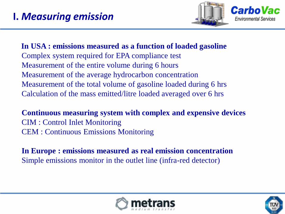
In USA : emissions measured as a function of loaded gasoline
Complex system required for EPA compliance test
Measurement of the entire volume during 6 hours
Measurement of the average hydrocarbon concentration
Measurement of the total volume of gasoline loaded during 6 hrs
Calculation of the mass emitted/litre loaded averaged over 6 hrs
Continuous measuring system with complex and expensive devices
CIM : Control Inlet Monitoring
CEM : Continuous Emissions Monitoring
In Europe : emissions measured as real emission concentration
Simple emissions monitor in the outlet line (infra-red detector)
I. Measuring emission

Refinery
Terminal Service-
station
Car filling
Losses : 0,1 kg/m3Emission reduction measures up to 99%
Losses : 1 kg/m3Emission reduction measures up to 90%
Losses : 1 kg/m3Emission reduction measures up to 99%
Losses : 1 kg/m3Emission reduction measures up to 99,99 %
I. Recovery Chain
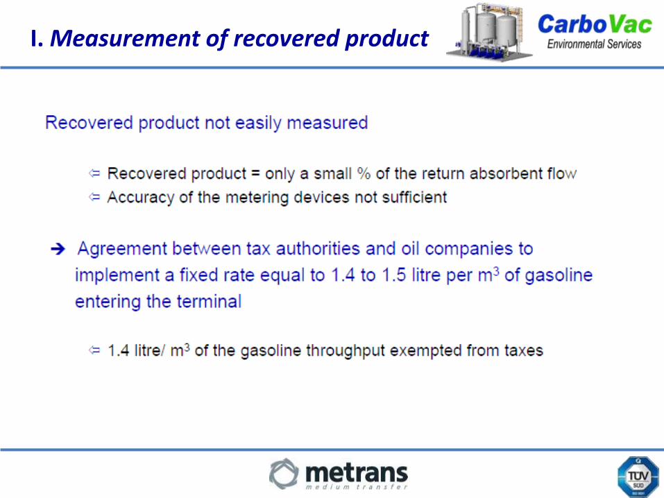
I. Measurement of recovered product

Hypotheses :
Vapor inlet concentration : 40 % Volume
Average outlet concentration :
Average MW :
2g / Nm-3
65 (Gasoline vapours)
Masse of hydrocarbons recovered 1159.5 g / m-3 of inlet vapor
The recovery rate :
The effective recovery rate is 1 . 49 liter per m-3 Inlet vapor Vapor recovery rate 99. 9 %.
Calculation :
0.4 x 65Mass of hydrocarbons at inlet per m-3 = = 1160,7 g / m-3
22.4 x 10 - 3
Masse of hydrocarbons in the outlet per m-3 inlet = 2 x (1 - 0.4) = 1.2 g / m-3
I. Calculation
I. Why to install a VRU ?
II. Terminal conditions for VRU implementations
III. Recovery based on AC technology
IV. A VRU in your terminal
V. Conclusion and Questions

Service-station :
– Pressure / vacuum relief valve to be installed in the
ground tank vent line
– Vapour return connection to be installed on the tank
vent line
II. Implementation of Stage 1…

II. EC Directive 94/63 Stage 1 and 2 for fuel distribution

II. Typical compartment truck
Truck:Truck modified to bottom loading
Overfill protection
All compartments connected to a central vapour collecting
line equipped with 4" API coupler with check valve.

II. Typical compartment truck
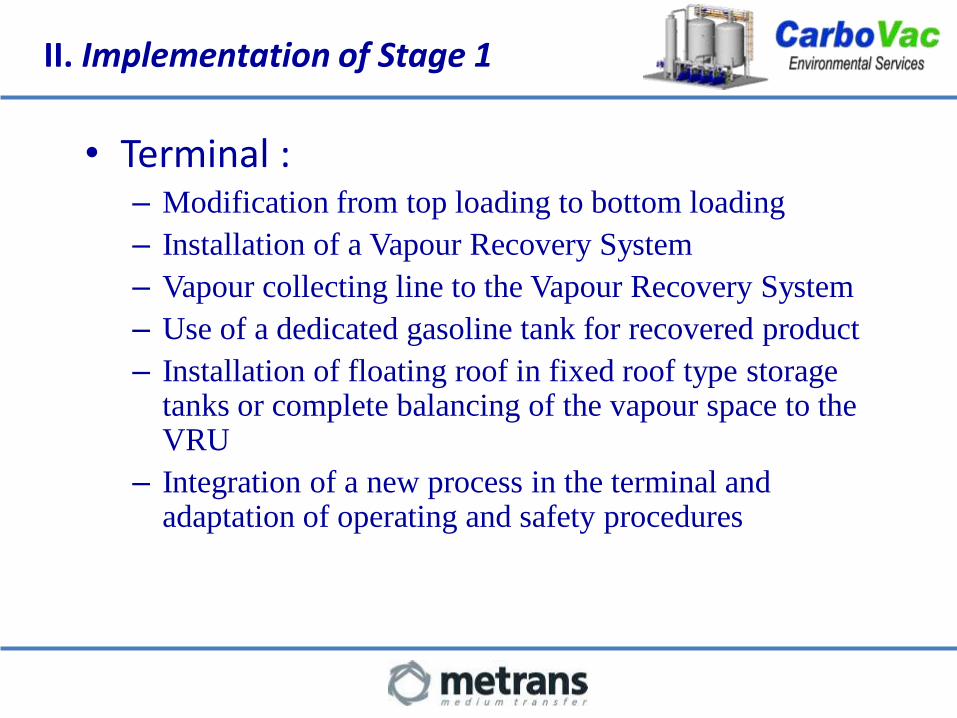
• Terminal :– Modification from top loading to bottom loading
– Installation of a Vapour Recovery System
– Vapour collecting line to the Vapour Recovery System
– Use of a dedicated gasoline tank for recovered product
– Installation of floating roof in fixed roof type storage tanks or complete balancing of the vapour space to the VRU
– Integration of a new process in the terminal and adaptation of operating and safety procedures
II. Implementation of Stage 1
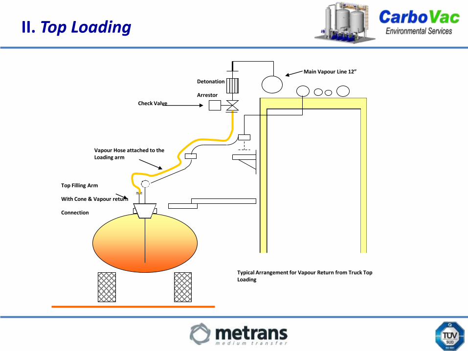
Main Vapour Line 12”
Top Filling Arm
With Cone & Vapour return
Connection
Vapour Hose attached to the Loading arm
Detonation
Arrestor
Check Valve
Typical Arrangement for Vapour Return from Truck Top Loading
II. Top Loading
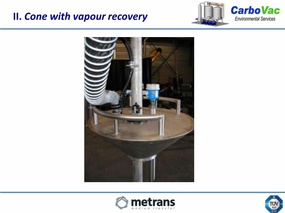
II. Cone with vapour recovery
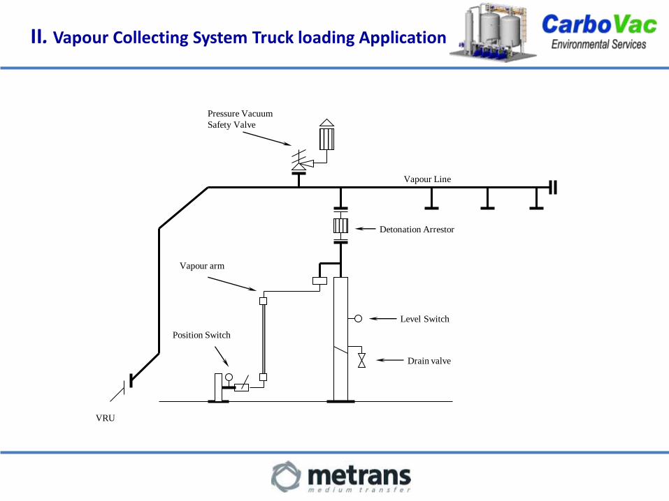
Vapour Line
Pressure Vacuum
Safety Valve
Detonation Arrestor
Level Switch
Drain valve
Vapour arm
Position Switch
VRU
II. Vapour Collecting System Truck loading Application

II. Bottom loading bays

I. Why to install a VRU ?
II. Terminal conditions for VRU implementations
III. Recovery based on AC technology
IV. A VRU in your terminal
V. Conclusion and Questions

III. Adsorption on Activated Carbon

III. Adsorption on Activated Carbon
The recovery process consists of 3 parts
1 - Adsorption of the hydrocarbons on activated carbon
2 - Regeneration of the carbon by means of vacuum
3 - Re-absorption of the hydrocarbons in a liquid product

III. Adsorption on Activated Carbon

During the loading of gasoline and diesel in trucks, the concentration of
the vapours may vary between 0 to 50 % Vol. depending of :
• the nature of the products previously loaded.• the loading station
Theses hydrocarbons are generally composed (% Vol) of :
C1 0 - 0.2.
C2 0 - 0.45
C3 1.5 - 3.8
C4 37 - 50
C5 22 - 43
C6 8 - 12
C7++ 1.7 - 5.4
Benzene 0.26 - 2.6
Toluene 0.36 - 1.8
III. Vapour composition

• Activated Carbon = most used adsorbents in the world
• Obtained through carbonization and activation of natural products and mineral charcoal
• The adsorption capacity depends on :
– Specific internal surface (up to 1800 m2/gram)
– Pore size and distribution
– Base material properties
III. Adsorption on Activated Carbon

Heat released : 350 kJ / kg of hydrocarbons (exothermic) The adsorption effect improves with :
Heat required : 2200 kJ / kg of water (endothermic) increase of the pressure
Equilibration of the temperature decrease of the temperature increase of the concentration
Large HC molecules are better adsorbed Selective recovery The phenomenon is reversible
The concentration of HC’s is increased
HC molecules
Water molecules
III. Adsorption on Activated Carbon
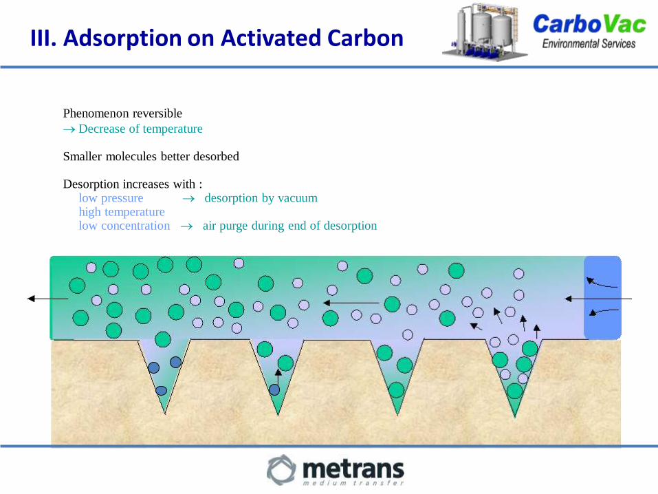
Phenomenon reversible
Decrease of temperature
Smaller molecules better desorbed
Desorption increases with :low pressure desorption by vacuumhigh temperature low concentration air purge during end of desorption
III. Adsorption on Activated Carbon
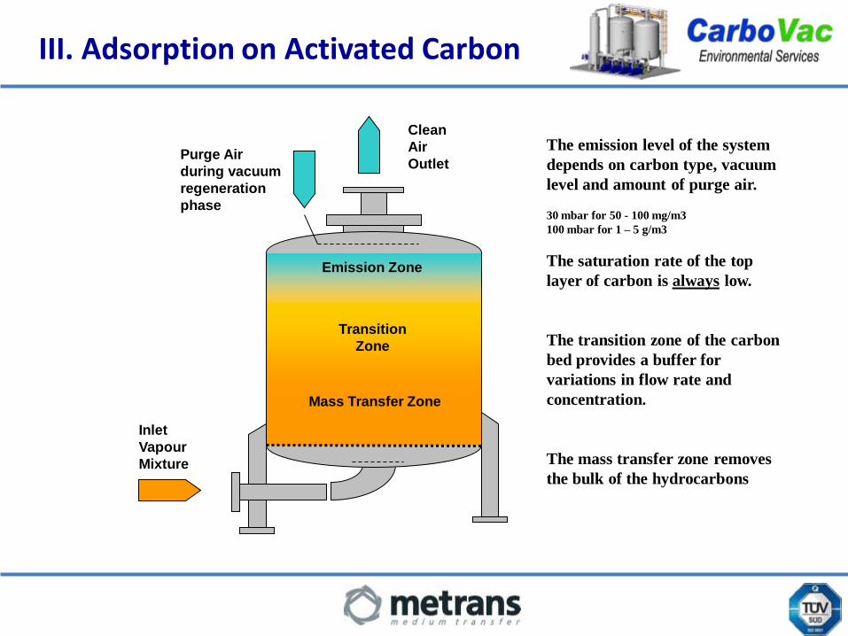
III. Adsorption on Activated Carbon
Clean
Air
OutletPurge Air
during vacuum
regeneration
phase
Emission Zone
Transition
Zone
Mass Transfer Zone
Inlet
Vapour
Mixture
The emission level of the system
depends on carbon type, vacuum
level and amount of purge air.
30 mbar for 50 - 100 mg/m3
100 mbar for 1 – 5 g/m3
The saturation rate of the top
layer of carbon is always low.
The transition zone of the carbon
bed provides a buffer for
variations in flow rate and
concentration.
The mass transfer zone removes
the bulk of the hydrocarbons
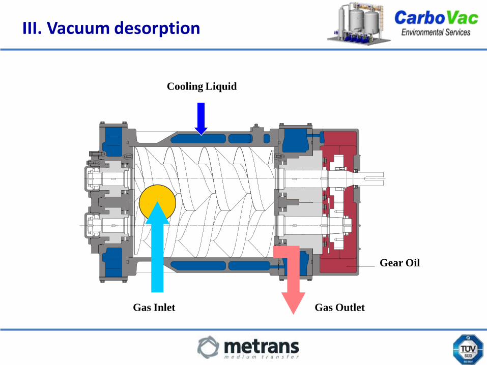
III. Vacuum desorption
Gas Inlet Gas Outlet
Cooling Liquid
Gear Oil

III. CarboVac Technology
The dry technology permits to reduce the system to the essential components
required for functioning.
The vacuum pumps used in the CarboVac technology are totally dry and
cause no pollution of the recovered products, eliminating all corrosion and
abrasion problems related to “wet” systems.
The absence of glycol or any other seal fluids (compatibility problem) and a
deep vacuum level offers the possibility to treat a vast range of products:
- Alcohol (Methanol, Ethanol)
- ETBE
- MTBE
- Benzene (BTX)
- Crude Oil
- Gasoline…

III. Vacuum desorptionGASOLINE CIRCULATION
I. Why to install a VRU
II. Terminal conditions for VRU implementations
III. Recovery based on AC technology
IV. A VRU in your terminal
V. Conclusion and Questions

PLC Powe
r
Truck Loading
Facility
Tank A
Tank B
P31P32
Vapour lines
Gasoline lines
CablingPC
IV. VRU in a terminal
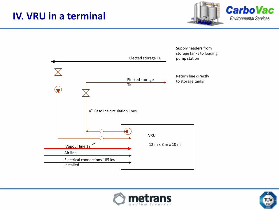
IV. VRU in a terminal
Return line directly to storage tanks
Supply headers from storage tanks to loading pump station
VRU =
12 m x 8 m x 10 mVapour line 12 ” Air line
4” Gasoline circulation lines
Electrical connections 185 kw installed
Elected storage TK
Elected storage TK
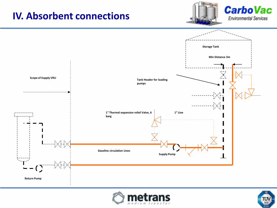
IV. Absorbent connections
Scope of Supply VRUTank Header for loading pumps
1” Thermal expansion relief Valve, 6 barg
Gasoline circulation Lines
Storage Tank
1” Line
Min Distance 3m
Return Pump
Supply Pump

IV. VRU integrated
Vapour
Recovery
Unit
Cabling
Nitrogen
Water
Gasoline
in out
Foundation drainage
Modem lineOpen/close Emergency VentEmergency vent valve positionPowerInput (start/stop truck loading)Gasoline pump start /stop/running signalSite ESD signalVRU runningVRU alarm
Air Compressor(instrument quality)
Control building
modem
Operations Room PC &interactive keyboard
Cabling

IV. Civil work
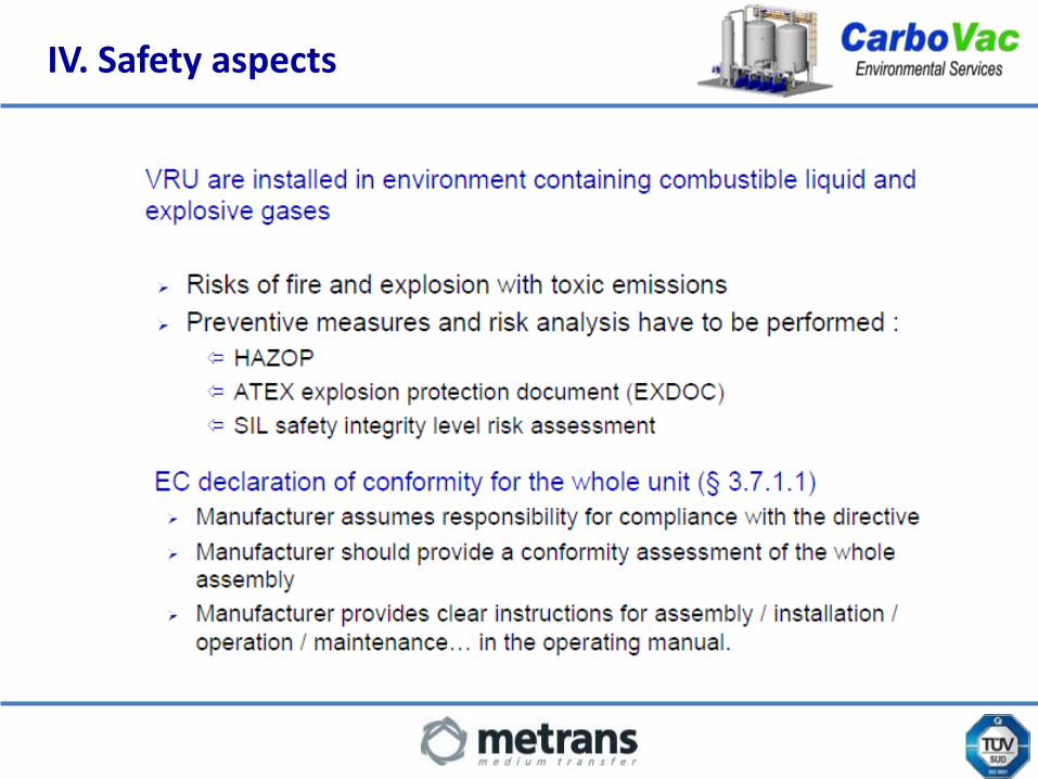
IV. Safety aspects

IV. Safety aspects

IV. VRU safety aspects

IV. VRU safety aspects

I. Why to install a VRU ?
II. Terminal conditions for VRU implementations
III. Recovery based on AC technology
IV. A VRU in your terminal
V. Conclusion and Questions

V. Conclusion and Questions