drucktaupunkt-fühler 0636.9880 / 0636.9881 ... · standardfühler 0636.9880 - ptfe-sinterkappe...
TRANSCRIPT

Bedienungsanleitung de
Drucktaupunkt-Fühler 0636.9880 / 0636.9881
Instruction manual en
Inhalt
Gerätebeschreibung..................................................................3
Benutzerhinweise ......................................................................4
Sicherheitshinweise ..................................................................5
Inbetriebnahme..........................................................................6Der Drucktaupunkt-Fühler .....................................................6
Messen .......................................................................................7
Wartung ......................................................................................8
Kontroll- und Abgleichmöglichkeiten......................................9
Technische Daten.....................................................................12Garantie................................................................................12
Bestelldaten ..............................................................................13
Anhang A...................................................................................13Erforderliche Drucktaupunktwerte tpd ....................................13
Anhang B...................................................................................14Taupunktdiagramm für Druckluft ..........................................14
Garantie Testo Deutschland....................................................15
Testo weltweit
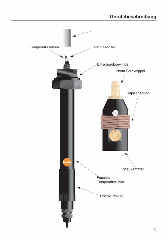
Gerätebeschreibung
3
PTFE-Sinterkappe
FeuchtesensorTemperatursensor
Norm-Stecknippel
Kapillarleitung
Feuchte- Temperaturfühler
Einschraubgewinde
Meßkammer
Überwurfhülse

Benutzerhinweise
Die beiden Drucktaupunkt-Fühler garantieren dasschnelle und präzise Bestimmen des Drucktaupunk-tes.
Die Entwicklung erfolgte in Zusammenarbeit miteinem weltweiten Marktführer im Bereich der Druck-lufttechnik.
Der Standardfühler 0636.9880 genügt für die mei-sten Messungen in Druckluftleitungen (z.B. an Kälte-trocknern im Bereich von 0...2 °C tpd). Der Präzi-sionsfühler 0636.9881 ist der ideale Fühler fürhochgenaue Messungen im Restfeuchtebereich (z.B. an Adsorptionstrocknern bis -50 °C tpd).
Der Drucktaupunkt tpd ist die Temperatur, bei der dieDruckluft den Sättigungszustand (100% rF) erreicht.Dieser Wert ist ein wichtiges Kriterium für die einwandfreie Funktion der Druckluftanlage.
Der Anschluß an das Druckluftsystem erfolgt übereine Normsteckverbindung (G1/4ý Innengewindenach ISO 228-1) bzw. über eine Prüfanschluß-Schraubverbindung bei Messungen an Fahrzeugen.Bei Bedarf können aber auch andere Normsteck-verbindungen mit Gewinde G 1/4ý in die Meßkam-mereingeschraubt werden.
Bei der Messung wird der Sensor kontinuierlich mitder zu messenden Druckluft angeströmt.
Ohne Meßkammer können die Fühler zur Feuchte-und Temperaturmessung gemäß der Bedienungsan-leitung der Geräte testo 600/601 eingesetzt werden.
In Verbindung mit den Meßgeräten testo 600/601steht dem Anwender ein tragbares, netzunabhängi-ges Meßsystem zur Verfügung. Auf dem zwei-zeiligen Display wird die relative Feuchte bzw. derTaupunkt und die Temperatur angezeigt.
Bei Verwendung des Meßgerätes testo 601 könnenSie die Meßwerte mit dem aufsteckbaren Recorderspeichern bzw. ausdrucken und über den PC-Adapter in Ihren PC übertragen.
4
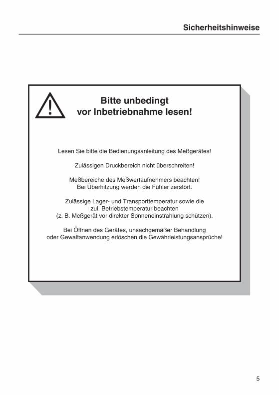
Sicherheitshinweise
Bitte unbedingt vor Inbetriebnahme lesen!
Lesen Sie bitte die Bedienungsanleitung des Meßgerätes!
Zulässigen Druckbereich nicht überschreiten!
Meßbereiche des Meßwertaufnehmers beachten!Bei Überhitzung werden die Fühler zerstört.
Zulässige Lager- und Transporttemperatur sowie diezul. Betriebstemperatur beachten
(z. B. Meßgerät vor direkter Sonneneinstrahlung schützen).
Bei Öffnen des Gerätes, unsachgemäßer Behandlung oder Gewaltanwendung erlöschen die Gewährleistungsansprüche!
5

Inbetriebnahme
Der Drucktaupunkt-Fühler
Die Meßkammer auf den Adapter des Feuchtefühlersaufsetzen. Fühler von Hand, druckdicht verschrau-ben.
Der Feuchtefühler kann auch ohne PTFE-Sinterkap-pe verwendet werden, in diesem Fall verkürzen sichdie Einstellzeiten. Allerdings kann eine Verschmut-zung bzw. Beschädigung der Sensoren bei der Mon-tage oder im Einsatz nicht ausgeschlossen werden.Nach Möglichkeit Fühler immer mit Sinterkappe ver-wenden. Bei absolut ölfreier Druckluft kann derMetallschutzkorb (Best.-Nr. 0554.0755) eingesetztwerden.
Stecker in die entsprechende Buchse des Meßgerä-tes stecken.
Um einen realistischen Meßwert zu erhalten, wirdempfohlen, an der Meßluft-Entnahmestelle ca. 10Sekunden Druckluft abströmen zu lassen.
Feuchtefühler an das Druckluftsystem anschließen. Über die Kapillarleitung strömt Druck-
luft ab (Verkürzung der Einstellzeiten).
6
Achten Sie darauf, daß die Meßkammer und dieKapillarleitung nicht verschmutzt sind!
������������
����
��
Die Druckreduzierung an der Entnahmestelle führt physikalisch bedingt zu einer
Reduzierung des Drucktaupunkt-Wertes.Siehe Tabelle Anhang B.

Messen
Handgerät einschalten.
Es erfolgt eine Testphase und im Displayerscheint die Batteriespannung des Handgerätesfür einige Sekunden.
Danach werden im Display die Meßwerte (%rFund °C) angezeigt.
Die Ansprechzeit beträgt 1...5 Minuten (typisch2 Minuten). Warten Sie bis die Meßwerte stabilsind (ca. 60 Sek. keine Veränderung der Meß-werte).
Nun kann der Drucktaupunkt mit der Funktionsta-ste abgefragt werden.Die anwenderspezifischen Drucktaupunkte tpd fin-den Sie im Anhang.
7
Die Lagerung des Feuchtefühlers bei starkabweichenden Temperatur- und Feuchtewerten
von der zu messenden Druckluft, sowie verschmutzte Sensoren bzw.
PTFE-Sinterkappen verlängern die Einstellzeit.
Bitte lesen Sie vor dem Einschalten desMeßgerätes die zum Gerät gehörende
Bedienungsanleitung um Meßfehler und Schäden amGerät zu vermeiden!
Bei Unterschreitung des Meßbereiches< 0,1%rF schaltet das Gerät automatisch ab. Dies entspricht einem Drucktaupunktvon <-50 °C bei 25 °C Nenntemperatur.
-2222..99 CCtd°
������������ ������
��
���������
��
��
��
�

Wartung
Im Fühlerkopf befindet sich ein robuster, langzeitsta-biler Feuchtesensor.
Je nach Einsatz und Verschmutzung empfehlen wireine jährliche bis viertel-jährliche Kontrolle mit unse-rem Kontroll- und Abgleichset 0554.0660. BeachtenSie die Hinweise auf Seite 10.
Verschmutzte Sensoren mit Alkohol (Isopropanol)oder destilliertem Wasser reinigen.Meßkammer und PTFE-Sinterkappe abschrauben.Sensor in Alkohol schwenken, in dest. Wasserspülen und anschließend an der Luft trocknen lassen.PTFE-Sinterkappe aufsetzen und festschrauben.
Defekte Sensoren können ausgetauscht werden,wenden Sie sich bitte an unseren Service.
Verschmutzte PTFE-Sinterkappen können Sieebenfalls mit reinem Alkohol und destilliertem Was-ser reinigen. Verunreinigungen lassen sich durchAusblasen mit Druckluft beseitigen. Bitte die Kappeimmer von innen nach außen ausblasen.
Verschmutzte Meßkammern werden in Wasserbzw. Alkohol gespült oder mit Druckluft ausgeblasen.
Bei einem Defekt an der Meßkammer wenden Siesich bitte an unseren Service.
8
Sensor nicht berühren und nicht anstoßen!

Kontroll- und Abgleichmöglichkeiten
Das Kontroll- und Abgleichset (Best.-Nr.: 0554.0660)dient zur Kontrolle und zum Abgleich von Feuchte-fühlern. Das Set besteht aus zwei Spezialbehältern.Mit Hilfe von verschiedenen Salzlösungen werdenLuftgemische mit definierten relativen Feuchten er-zeugt (weitere Informationen siehe Bedienungsan-leitung ”Kontroll- und Abgleichset für Feuchtesenso-ren”).
Im Rahmen der Akkreditierung als Kalibrierlabora-torium für die Meßgrößen ”Relative Feuchte” und”Taupunkt” wurden die Werte für die relative Feuch-te über gesättigten Lithiumchlorid (LiCl) und Natrium-chlorid (NaCl) Lösungen bei testo neu spezifiziert.
Diese verbesserten Werte gelten auch für alle bishergelieferten Kontroll- und Abgleichsets entgegen derbislang spezifizierten Werte.
9
LiCl 11,3% rF, NaCl 75,3% rFbei Nenntemperatur +25 °C
Temperaturabhängigkeit
Lithiumchlorid
Temperatur LiClMittelwert Toleranz
10 °C 11,29 % ± 0,41 %15 °C 11,30 % ± 0,35 %20 °C 11,31 % ± 0,31 %25 °C 11,30 % ± 0,27 %30 °C 11,28 % ± 0,24 %
Natriumchlorid
Temperatur NaClMittelwert Toleranz
10 °C 75,67 % ± 0,22 %15 °C 75,61 % ± 0,18 %20 °C 75,47 % ± 0,14 %25 °C 75,29 % ± 0,12 %30 °C 75,09 % ± 0,11 %

Kontroll- und Abgleichmöglichkeiten
Allgemeine Hinweise
Die Feuchtefühler 0636.9880 und 0636.9881 durch-laufen bei testo ein aufwendiges Abgleichverfahren.Vor der Kontrolle bzw. dem Abgleich müssen dieFühler und das Kontroll- und Abgleichset bei einerkonstanten Temperatur (+20...+30 °C) ca. 12 Stun-den gelagert werden. Die Mindestangleichzeit beträgtbei eingeschraubten Fühler in die Prüfbehälter 15Minuten.
Kontrolle und/oder Abgleich
Standardfühler 0636.9880
- PTFE-Sinterkappe vorsichtig abschrauben- Überwurfhülse abschrauben- Fühler in Prüfbehälter LiCl (11,3%) einschrauben- Angleichzeit 15 Minuten- Kontrolle auf dem Display des Handgerätes- Gegebenenfalls abgleichen mit Tastendruck P1 = 11,3% rF ± 2% rF
- Fühler aus Prüfbehälter LiCl herausdrehen- Fühler in Prüfbehälter NaCl (75,3%) einschrauben- Angleichzeit 15 Minuten- Kontrolle auf dem Display des Handgerätes- Gegebenenfalls abgleichen mitTastendruck P2 = 75,3% rF ± 2% rF
- Fühler aus Prüfbehälter NaCl herausdrehen- PTFE-Sinterkappe vorsichtig aufschrauben- Überwurfhülse festschrauben
Präzionsfühler 0636.9881
Der Präzisionsfühler wird zusätzlich zum Standard-abgleich einem Feinabgleich im Werk bei -40 °CDrucktaupunkt unterzogen.Eine Kontrolle mit dem Kontroll- und Abgleichset istmöglich. Für den Abgleich der Präzisionsfühler sinddie Salztöpfchen nicht geeignet. Ein Präzisionsab-gleich ist nur bei testo durchzuführen oder mit ent-sprechend hochpräzisen Referenzsystemen (Tau-punktspiegelmeßgeräte für Druckluft).
10
P1
P2
Überwurfhülse

Kontroll- und Abgleichmöglichkeiten
Feinabgleich
Bei den Fühlern 0636.9880 und 0636.9881 bestehtdie Möglichkeit einen Feinabgleich auf einem beliebi-gen Drucktaupunkt im Bereich -50...+25 °C tpd bei+25 °C durchzuführen (Einpunktabgleich).
AchtungDer Feinabgleich ist nur sinnvoll bei Verwendung vonhochpräzisen Referenzsystemen und bei Beachtungentsprechender Angleichzeiten (mindestens 15 Minu-ten).Der Fühler 0636.9881 ist bereits werkseitig fürdie Feuchtemessung in Druckluftanlagen optimiert.
Durchführung des Feinabgleichs
- Überwurfhülse abschrauben- Drehschalter nach rechts auf ”Offset” stellen- Mit Taste P1 (Down) Meßwerte nach unten korrigie-ren
- Mit Taste P2 (Up) Meßwerte nach oben korrigieren
Die zuletzt eingestellten Werte auf dem Display desHandgerätes werden gespeichert.
Werkseinstellung
Die eingestellte Feinkorrektur wird unwirksam, wennDrehschalter nach links gedreht wird (Schalter-stellung ”Abgleich/Kalibration”).
11
� �!
"���
OffsetAbgleichCalibrationEtalennage
11,3%(DOWN)
75,3%(UP)
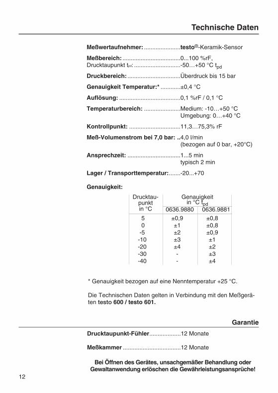
Garantie
Drucktaupunkt-Fühler...................12 Monate
Meßkammer ...................................12 Monate
Bei Öffnen des Gerätes, unsachgemäßer Behandlung oderGewaltanwendung erlöschen die Gewährleistungsansprüche!
12
Technische Daten
Meßwertaufnehmer: ......................testo®-Keramik-Sensor
Meßbereich: ...................................0...100 %rF,Drucktaupunkt tpd: ............................-50…+50 °C tpd
Druckbereich: ................................Überdruck bis 15 bar
Genauigkeit Temperatur:* ............±0,4 °C
Auflösung: .....................................0,1 %rF / 0,1 °C
Temperaturbereich: ......................Medium: -10…+50 °CUmgebung: 0…+40 °C
Kontrollpunkt: ...............................11,3…75,3% rF
Meß-Volumenstrom bei 7,0 bar: ..4,0 l/min (bezogen auf 0 bar, +20°C)
Ansprechzeit: ................................1...5 mintypisch 2 min
Lager / Transporttemperatur:.......-20...+70
Genauigkeit:
* Genauigkeit bezogen auf eine Nenntemperatur +25 °C.
Die Technischen Daten gelten in Verbindung mit den Meßgerä-ten testo 600 / testo 601.
50
-5-10-20-30-40
±0,9±1±2±3±4--
±0,8±0,8±0,9±1±2±3±4
Genauigkeitin °C tpd
0636.9880 0636.9881
Drucktau-punktin °C

13
Bestelldaten
Beschreibung Best.-Nr.
Standardfühler.................................0636.9880Meßkammer, Bedienungsanleitung
Präzisionsfühler ..............................0636.9881Meßkammer, Bedienungsanleitung
Meßkammer ....................................0554.9860
Feuchtesensor.................................0420.0023
Temperatursensor...........................0420.1242
Feuchtekontroll- und Abgleichset ..0554.066011,3% rF, 75,3% rF, Bedienungsanleitung
PTFE-Sinterkappe ..........................0554.0756
Metallschutzkorb .............................0554.0755
Kalibrierzertifikat .............................0520.0306
Erforderliche Drucktaupunktwerte tpd
An die Druckluftqualität werden je nach Anwendung verschiedeneAnforderungen gestellt.Da die Korrosionsgeschwindigkeit ab ca. 50 % rF auf Stahlober-flächen stark zunimmt sollte dieser Wert auf keinen Fall überschrittenwerden.
Anwendungsgebiet erforderliche Drucktaupunkte tpdWerksluft, Innenleitungen 10 °C … -10 °CFarbspritzen 10 °C … -25 °CInstrumentenluft 10 °C … -40 °CSandstrahlgebläse 5 °C … 0 °CPneumatische Werkzeuge 5 °C … -25 °CPneumatische Förderung 5 °C … -60 °C
Verkehrsfahrzeuge (Omnib., etc.) -13 °C … -33 °C
Reinigung optischer Systeme -17 °C … -33 °CTrocknung elektr. Komponenten -20 °C … -40 °CWerksluft, Außenleitungen -20 °C … -40 °CChem. und pharmazeut. Werke -25 °C … -40 °C
Der Drucktaupunkt tpd ist die Temperatur,bei der die Druckluft den
Sättigungszustand (100 % rF) erreicht hat.
Anhang A

14
Anhang B
Taupunktdiagramm für Druckluft
Dieses Diagramm gibt Aufschluß über dieDrucktaupunkt-Veränderung bei Druckverlust.Als Beispiel ist ein Druckverlust von 8 bar auf
6 bar Betriebsüberdruck dargestellt. DerDrucktaupunkt wandert in diesem Falle
von 10 °C auf 5°C ab.
���������� ���
������ �� �������
���
����
������
���
�
� � � � � �� �� ��
� � � � � �� �
���
���
���
���
���
���
���
�
�
�
�
�
��
��
��
��
��
��
���
���
��
�
�
�
��
��
��
��
��
��
��
��
��
��
� �
��
�� �� �� ��
�� �� ��
��
� � �
��
���
���
���
��� ���
��
��
��
���
��
����
����
��� �!�
��" �
���#
��$��
���$
��%�
��$��
���
����
&� ������
���$ �"
� �
Garantie Testo Deutschland
15
Sehr geehrte Kundin,sehr geehrter Kunde,
vielen Dank für das Vertrauen, das Sie Testo mit dem Kauf dieses Meßgerätes entgegen-gebracht haben. Sie haben eine gute Wahl getroffen. Sollten Sie trotzdem Grund zurBeanstandung unseres Produktes haben, beheben wir Mängel kostenlos, die nachweislichauf einen Werksfehler beruhen. Voraussetzung ist, daß Sie diesen Mangel unverzüglichnach Feststellung und innerhalb der von uns gewährten Garantiezeit melden.
Natürlich sind Verschleißteile wie zum Beispiel Akkus, Meßzellen, Filter, Meßelementeusw. sowie leicht zerbrechliche Teile von dieser Garantie ausgenommen. EbensoSchäden, die durch nicht bestimmungsgemäßen Gebrauch sowie infolge von Nichtbeach-tung der Bedienungsanleitung entstanden sind.
Die Garantie entfällt außerdem, wenn das Meßgerät geöffnet wurde - soweit dies nichtausdrücklich in der Bedienungsanleitung zu Wartungszwecken beschrieben ist - oder aberSeriennummern im Gerät verändert, beschädigt oder entfernt wurden.
Die Garantiezeit beträgt für Drucktaupunkt-Fühler und Meßkammer 12 Monate,. Wennnicht anders definiert, gelten für Zubehörteile 6 Monate. Garantieleistungen bewirken keineVerlängerung der Garantiefrist.
Wurden neben der Garantieleistung notwendige Reparaturen, Justagen oder dergleichendurchgeführt, sind die Garantieleistungen kostenlos, die anderen Leistungen werden aberebenso wie Transport und Verpackung berechnet.
Weitergehende oder andere Ansprüche, insbesondere bei entstandenen Schäden dienicht das Gerät betreffen sind - soweit eine Haftung nicht zwingend gesetzlich vorgeschrie-ben ist - ausgeschlossen.
Leistungen nach der Garantiezeit
Selbstverständlich sind wir auch nach Ablauf der Garantiezeit für Sie da. Bei Funktions-störungen senden Sie uns Ihr Meßgerät mit einer kurzen Fehlerbeschreibung. Geben Siebitte auch Ihre Telefonnummer für eventuelle Rückfragen an.
Bei uns wird KUNDENDIENST groß geschrieben.

Bedienungsanleitung de
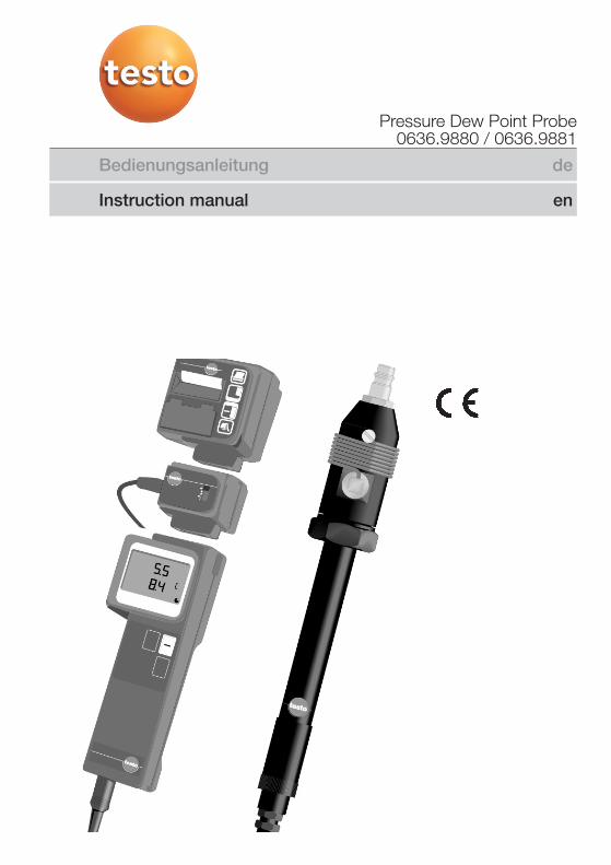
Pressure Dew Point Probe0636.9880 / 0636.9881
Instruction manual en

Contents
Instrument description..............................................................3
User instructions .......................................................................4
Safety instructions ....................................................................5
Operating instructions ..............................................................6The pressure dew point probe...............................................6
Measuring...................................................................................7
Maintenance...............................................................................8
Control and calibration options ...............................................9
Technical data...........................................................................12Warranty ...............................................................................12
Ordering data ............................................................................13
Appendix A................................................................................13Necessary pressure dew point values tpd ..............................13
Appendix B................................................................................14Dew point graph for compressed air.....................................14
Warranty from Testo Germany................................................15
Testo worldwide

Instrument description
3
PTFE sintered cap
Humidity sensorTemperature sensor
Standard plug-in nipple
Capillary wire
Humidity/temperature probe
Internal thread
Measuring chamber
Protective sleeve

User instructions
The two pressure dew point probes guarantee quickand accurate dew point measurement.
The probe was developed in cooperation with a worldmarket leader in the compressed air engineering sec-tor.
The standard probe 0636.9880 is sufficient for mostmeasurements in compressed-air piping (e.g. refrige-ration dryers in the range from 0 to 2 °C tpd). Theprecision probe 0636.9881 is the ideal probe forhighly accurate measurements in the remaininghumidity range (e.g. in adsorption dryers to -50 °C tpd).
The pressure dew point tpd is the temperature atwhich compressed air reaches the saturation state(100% RH). This value is an important criteria for theperfect running of the compressed air plant.
The probe is connected to the compressed airsystem via a standard plug-in connector (G1/4ý inter-nal thread to ISO 228-1) or via a screw-on adapterfor measurements at test points. If required otherstandard plug-in connectors with thread G 1/4ý canbe screwed into measuring chamber.
The sensor is positioned in the flow of compressedair being measured, for the duration of the measure-ment.
The probes can be used, without a measuring cham-ber, in accordance with the Instruction Manual for thetesto 600/601 instruments.
By connecting the probe to testo 600/601 the userhas a portable, mains independent measuringsystem. The large, two line display enables the dis-play of the relative humidity or the dew point with thetemperature.
When using the testo 601 measuring instrument, youcan store and print-out the measured values with theplug-in logger or transfer to your PC via the PC adapter.
4

Safety instructions
Read before using the instrument
Please read the Instruction Manual belonging to the measuring instrument.
Do not exceed the permissible pressure range.
Observe the measuring range of the sensor.Overheating can destroy the probe.
Observe the permissible storage and transport temperatureas well as the permissible operating temperature
zul. Betriebstemperatur beachten (e.g. protect the measuring instrument from direct sunlight).
If the instrument is opened, improperly handled of if force is applied, the warranty will no longer be valid.
5

Operating instructions
The pressure dew point probe
Place the measuring chamber on the humidity probeadapter and screw on tightly by hand.
The humidity probe can also be used without thePTFE sintered cap, in which case the response timesare shorter. However, the probes can become dirtyor damaged during assembly or application.If possible always use a sintered cap with the probe.A metal protection cage (Order no. 0554.0755) canbe used with absolute oil-free compressed air.
Connect the plug to the corresponding socket on themeasuring instrument.
In order to obtain a real measuring value, let com-pressed air escape from the outlet for about 10seconds.
Connect the humidity probe to the compressed airplant. Compressed air flows out of the capillary wire
(shortening of the response times).
6
Make sure that the measuring chamber and capillary wire are not dirty.
������������
����
��
The reduction of pressure at the outlet leads to aphysical reduction in the pressure dew point value.
See the table in appendix B.

Measuring
Switch on the hand-held instrument.
A segment test is carried out followed by a dis-play of the battery voltage for several seconds.
The measured values (%RH and °C) are thendisplayed.
The response time is 1 to 5 minutes (typically2 minutes). Wait until the measured values arestable (approx. 60 s without a change in the mea-sured values).
The dew pressure point can now be called upwith the function key.The user-specific pressure dew point tpd can nowbe found in the appendix.
7
The storage of the humidity probe in areas withtemperature and humidity values which differ
considerably from those of the compressed airbeing measured, and dirty sensors or sintered
caps increase the response times.
Please read the instrument instruction manual beforethe switching on the instrument, in order to avoid incorrect measuring results and damage to the
instrument.
The instrument switches itself off automaticallywhen the RH is < 0.1% RH.This corresponds to a pressure dew point of<-50 °C at 25 °C rated temperature.
-2222..99 CCtd°
������������ ������
��
���������
��
��
��
�
Maintenance
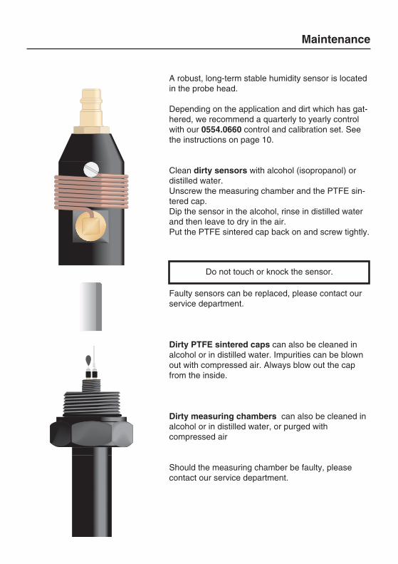
A robust, long-term stable humidity sensor is locatedin the probe head.
Depending on the application and dirt which has gat-hered, we recommend a quarterly to yearly controlwith our 0554.0660 control and calibration set. Seethe instructions on page 10.
Clean dirty sensors with alcohol (isopropanol) ordistilled water.Unscrew the measuring chamber and the PTFE sin-tered cap.Dip the sensor in the alcohol, rinse in distilled waterand then leave to dry in the air.Put the PTFE sintered cap back on and screw tightly.
Faulty sensors can be replaced, please contact ourservice department.
Dirty PTFE sintered caps can also be cleaned inalcohol or in distilled water. Impurities can be blownout with compressed air. Always blow out the capfrom the inside.
Dirty measuring chambers can also be cleaned inalcohol or in distilled water, or purged with compressed air
Should the measuring chamber be faulty, pleasecontact our service department.
8
Do not touch or knock the sensor.
Control and calibration options
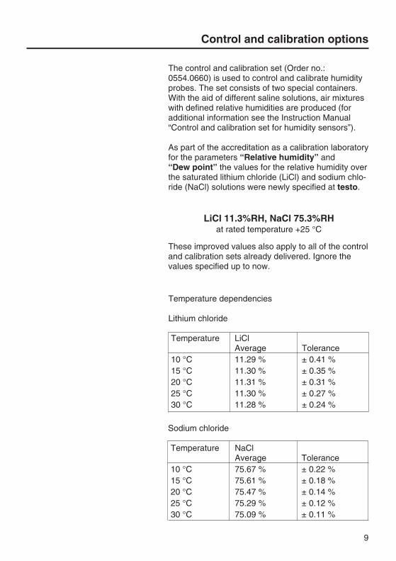
The control and calibration set (Order no.:0554.0660) is used to control and calibrate humidityprobes. The set consists of two special containers. With the aid of different saline solutions, air mixtureswith defined relative humidities are produced (foradditional information see the Instruction Manual“Control and calibration set for humidity sensors”).
As part of the accreditation as a calibration laboratoryfor the parameters “Relative humidity” and“Dew point” the values for the relative humidity overthe saturated lithium chloride (LiCl) and sodium chlo-ride (NaCl) solutions were newly specified at testo.
These improved values also apply to all of the controland calibration sets already delivered. Ignore thevalues specified up to now.
9
LiCl 11.3%RH, NaCl 75.3%RHat rated temperature +25 °C
Temperature dependencies
Lithium chloride
Temperature LiClAverage Tolerance
10 °C 11.29 % ± 0.41 %15 °C 11.30 % ± 0.35 %20 °C 11.31 % ± 0.31 %25 °C 11.30 % ± 0.27 %30 °C 11.28 % ± 0.24 %
Sodium chloride
Temperature NaClAverage Tolerance
10 °C 75.67 % ± 0.22 %15 °C 75.61 % ± 0.18 %20 °C 75.47 % ± 0.14 %25 °C 75.29 % ± 0.12 %30 °C 75.09 % ± 0.11 %

Control and calibration options
General information
The humdity probes 0636.9880 and 0636.9881undergo a comprehensive calibration procedure attesto. Before control and calibration, the probes mustbe stored at a constant temperature (+20 to +30 °C)for approximately 12 hours. The minimum adjustmenttime is 15 minutes in the test container with screwedin probes.
Control and/or calibration
Standard probe 0636.9880
- Carefully screw off the PTFE sintered cap- Screw off the protective sleeve- Screw the probe into the test container LiCl (11.3%)- 15 minute adjustment time- Control on the hand-held instrument display- Calibrate, if necessary, by pressing
P1 = 11.3%RH ± 2%RH- Screw out the probe from the LiCl test container- Screw the probe into the NaCl (75.3%) test container
- 15 minute adjustment time- Control on the hand-held instrument display- Calibrate, if necessary, by pressingP2 = 75.3%RH ± 2%RH
- Screw out the probe from the NaCl test container- Carefully screw on the PTFE sintered cap- Screw on the protective sleeve tightly
Precision probe 0636.9881
In addition to the standard calibration the precisionprobe is subjected to a fine calibration in the factoryat -40 °C pressure dew point.A control with the control and calibration set is possi-ble. The salt containers are not suitable for calibra-ting the precision probe. A precision calibration canonly be carried out at testo or with corresponding highly accurate reference systems (dew point mirrormeasuring instruments for compressed air).
10
P1
P2
Protectivesleeve
Control and calibration options
Fine calibration
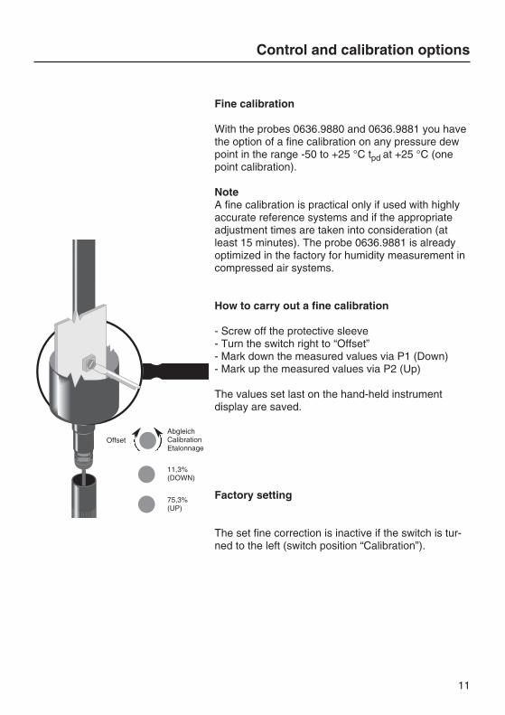
With the probes 0636.9880 and 0636.9881 you havethe option of a fine calibration on any pressure dewpoint in the range -50 to +25 °C tpd at +25 °C (onepoint calibration).
NoteA fine calibration is practical only if used with highlyaccurate reference systems and if the appropriateadjustment times are taken into consideration (atleast 15 minutes). The probe 0636.9881 is alreadyoptimized in the factory for humidity measurement incompressed air systems.
How to carry out a fine calibration
- Screw off the protective sleeve- Turn the switch right to “Offset”- Mark down the measured values via P1 (Down) - Mark up the measured values via P2 (Up)
The values set last on the hand-held instrument display are saved.
Factory setting
The set fine correction is inactive if the switch is tur-ned to the left (switch position “Calibration”).
11
� �!
"���
OffsetAbgleichCalibrationEtalonnage
11,3%(DOWN)
75,3%(UP)

Warranty
Pressure dew point probe ............1 year
Measuring chamber ......................1 year
If the instrument is opened, improperly handled or if force isapplied, the warranty will be no longer valid.
12
Technical data
Sensor:...........................................testo® ceramic sensor
Measuring range: ..........................0 to 100 %RH,Pressure dew point tpd: ....................-50 to +50 °C tpd
Pressure range:.............................Overpressure to 15 bar
Accuracy, temperature:*...............±0.4 °C
Resolution: ....................................0.1 %RH / 0.1 °C
Temperature range: ......................Probe: -10 to +50 °CInstrument: 0 to +40 °C
Control point: ................................11.3 to 75.3%RH
Measured volume flow at 7.0 bar:4.0 l/min (referred to 0 bar, +20°C)
Response time: .............................1 to 5 mintypically 2 min
Storage/transport temperature: ...-20 to +70
Accuracy:
* Accuracy referred to a rated temperature of +25 °C.
The Technical data applies in connection with the testo 600 /testo 601 measuring instrument.
50
-5-10-20-30-40
±0.9±1±2±3±4--
±0.8±0.8±0.9±1±2±3±4
Accuracyin °C tpd
0636.9880 0636.9881
Pressuredew point
in °C

13
Ordering data
Description Order no.
Standard probe................................0636.9880Measuring chamber, Instruction Manual
Precision probe ...............................0636.9881Measuring chamber, Instruction Manual
Measuring chamber .......................0554.9860
Humidity sensor ..............................0420.0023
Temperature sensor........................0420.1242
Humidity control and calibration set0554.066011.3%RH, 75.3%RH, Instruction Manual
PTFE sintered cap ..........................0554.0756
Metal protection cage .....................0554.0755
Calibration certificate .....................0520.0306
Necessary pressure dew point values tpd
Depending on the type of application, different requirements can bemade on the air quality.As the speed of corrosion on steel surfaces increases rapidly aboveapprox. 50%RH, this value should never be exceeded.
Field of application Necessary pressure dew point values tpdFactory air, internal pipes 10 °C to -10 °CPaint spraying 10 °C to -25 °CInstrument air 10 °C to -40 °CSand blasting machine 5 °C to 0 °CPneumatic tools 5 °C to -25 °CPneumatic conveyor belt 5 °C to -60 °C
Transport vehicles (bus, etc.) -13 °C to -33 °C
Cleaning of optical systems -17 °C to -33 °CDrying of electronic components -20 °C to -40 °CFactory air, external pipes -20 °C to -40 °CChem. and pharmaceutical plants -25 °C to -40 °C
The pressure dew point tpd is the temperature at which the compres-
sed air is fully saturated (100 %RH) .
Appendix A

14
Appendix B
Dew point graph for compessed air
This graph gives information on the change inthe pressure dew point at pressure loss. A
drop in working pressure from 8 bar to 6 bar isused as an example here. In this case
the pressure dew point is reduced from10°C to 5°C.
���������� ���
������ �� �������
���
����
������
���
�
� � � � � �� �� ��
� � � � � �� �
���
���
���
���
���
���
���
�
�
�
�
�
��
��
��
��
��
��
���
���
��
�
�
�
��
��
��
��
��
��
��
��
��
��
� �
��
�� �� �� ��
�� �� ��
��
� � �
��
���
���
���
��� ���
��
��
��
���
��
����
����
��� �!�
��" �
���#
��$��
���$
��%�
��$��
���
����
&� ������
���$ �"
� �
Gram
mes
of w
ater
vap
our p
er m
3 of
hum
idity
-sa
tura
ted
com
pres
sed
air
Pres
sure
dew
poi
nt (°
C)
AIR PRESSURE (bar)Working pressure
Warranty from Testo Germany
15
Dear Customer
Thank you for your confidence in Testo which you have shown by buying this measuringinstrument. You have made a wise choice. If you have reason for complaint we will repairany faults free of charge if it can be proven that they are manufacturing faults. The faultshould be reported immediately after it has been found and within the warranty timeguaranteed by us.
Excluded are working parts such as rechargeable batteries, measuring cells, filters,measuring elements etc. as well as fragile parts. Also not included is damage caused byimproper user and non-adherence to the Instruction Manual.
The warranty is also cancelled once the measuring instrument has been opened providedthis is not described in the Instruction Manual for maintenance purposes. This is also thecase if the serial number has been changed, damaged or removed.
The warranty time is 1 year for the pressure dew point probe and the measuring chamber,6 months for accessories, if not otherwise stated. After-sales service does not extend thewarranty time.
If in addition to the after-sales service necessary repairs, adjustments or similar are carriedout the after-sales service is free of charge but the cost of the other services are calculatedin additon to transport and packaging.
Other claims especially those for damage occurring outside the instrument are not includedunless responsibility is legally binding.
After-sales service after the warranty time has elapsed
We are, of course, there for you after the warranty time has elapsed. In the case offunctions faults please send us your measuring instrument with a brief description of thedefect. Include your telephone number should we need to contact you.
Testo at your service. Testo CUSTOMER SERVICE puts the customer first.

testo AG
Postfach 11 40, 79849 LenzkirchTesto-Straße 1, 79853 Lenzkirch
Telefon: (07653) 681-0Fax: (07653) 681-100
E-Mail: [email protected]: http://www.testo.com
0973 0600 01 de en