driver information system - boredmder - youtubeboredmder.com/fsms/nissan/maxima/2005/di.pdf ·...
TRANSCRIPT
DI-1
DRIVER INFORMATION SYSTEM
K ELECTRICAL
CONTENTS
C
D
E
F
G
H
I
J
L
M
SECTION
A
B
DI
Revision: July 2005 2005 Maxima
PRECAUTION ............................................................ 3Precautions for Supplemental Restraint System (SRS) “AIR BAG” and “SEAT BELT PRE-TEN-SIONER” .................................................................. 3Wiring Diagrams and Trouble Diagnosis .................. 3
PREPARATION ........................................................... 4Commercial Service Tool ......................................... 4
COMBINATION METERS ........................................... 5System Description .................................................. 5
UNIFIED METER CONTROL UNIT ...................... 5UNIFIED METER AND A/C AMP. ......................... 5HOW TO CHANGE THE DISPLAY FOR ODO/TRIP METER ........................................................ 6POWER SUPPLY AND GROUND CIRCUIT ........ 7WATER TEMPERATURE GAUGE ........................ 7TACHOMETER ..................................................... 7FUEL GAUGE ....................................................... 7SPEEDOMETER ................................................... 7
Component Parts and Harness Connector Location ..... 8Combination Meter ................................................... 9
CHECK .................................................................. 9Circuit Diagram ...................................................... 10Wiring Diagram — METER — .................................11Terminals and Reference Value for Combination Meter ...................................................................... 13Terminals and Reference Value for Unified Meter and A/C Amp. ......................................................... 14Meter/Gauge Operation and Odo/Trip Meter ......... 15
SELF-DIAGNOSIS FUNCTION .......................... 15HOW TO ALTERNATE DIAGNOSIS MODE ....... 15
CONSULT-II Function ............................................ 15How to Proceed With Trouble Diagnosis ................ 16Diagnosis Flow ....................................................... 16Power Supply and Ground Circuit Inspection ........ 17Symptom Chart 1 ................................................... 19Symptom Chart 2 ................................................... 19Vehicle Speed Signal Inspection ............................ 20Engine Speed Signal Inspection ............................ 22Water Temperature Signal Inspection .................... 23Fuel Level Sensor Signal Inspection 1 ................... 24
FUEL GAUGE ..................................................... 24Fuel Level Sensor Signal Inspection 2 ................... 25
LOW-FUEL WARNING LAMP ............................. 25Communication Line Inspection ............................. 25Fuel Gauge Pointer Fluctuates, Indicates Wrong Value, or Varies ...................................................... 28Fuel Gauge Does Not Move to Full-position ........... 28Electrical Components Inspection .......................... 29
FUEL LEVEL SENSOR UNIT CHECK ................ 29Removal and Installation of Combination Meter ..... 29
REMOVAL ........................................................... 29INSTALLATION ................................................... 29
UNIFIED METER AND A/C AMP .............................. 30System Description ................................................. 30
INPUT/OUTPUT SIGNALS ................................. 30FAIL-SAFE .......................................................... 31
CAN Communication System Description .............. 31Schematic ............................................................... 32CONSULT-II Function (METER A/C AMP) ............. 33
CONSULT-II BASIC OPERATION ....................... 33SELF-DIAGNOSTIC RESULTS ........................... 34DATA MONITOR ................................................. 34
Removal and Installation of Unified Meter and A/C Amp. ....................................................................... 36
REMOVAL ........................................................... 36INSTALLATION ................................................... 36
COMPASS ................................................................. 37System Description ................................................. 37
POWER SUPPLY AND GROUND CIRCUIT ....... 37CALIBRATION ..................................................... 37
Wiring Diagram — COMPAS — ............................. 38Trouble Diagnoses ................................................. 39
COMPASS INSPECTION .................................... 39Zone Variation Change Procedure ......................... 40
CALIBRATION FUNCTION OF COMPASS ........ 40WARNING LAMPS .................................................... 41
Schematic ............................................................... 41Wiring Diagram — WARN — .................................. 42Oil Pressure Warning Lamp Stays Off (Ignition Switch ON) ............................................................. 47

DI-2Revision: July 2005 2005 Maxima
Oil Pressure Warning Lamp Does Not Turn Off (Oil Pressure Is Normal) ................................................ 48Component Inspection ............................................ 49
OIL PRESSURE SWITCH ................................... 49A/T INDICATOR ........................................................ 50
Wiring Diagram — AT/IND — ................................. 50 ............................................................................. 50
Trouble Diagnosis ................................................... 51A/T Indicator Does Not Illuminate ........................... 51
WARNING CHIME ..................................................... 53Component Parts and Harness Connector Location ... 53System Description ................................................. 53
FUNCTION .......................................................... 53IGNITION KEY WARNING CHIME ...................... 53LIGHT WARNING CHIME ................................... 54SEAT BELT WARNING CHIME ........................... 54
CAN Communication System Description .............. 54Wiring Diagram — CHIME — ................................. 55Terminals and Reference Value for BCM ................ 57Terminals and Reference Value for Unified Meter
and A/C Amp. ..........................................................58Terminals and Reference Value for Combination Meter .......................................................................58How to Proceed With Trouble Diagnosis ................59Preliminary Check ...................................................59
INSPECTION FOR POWER SUPPLY AND GROUND CIRCUIT .............................................59
CONSULT-II Function (BCM) ..................................61CONSULT-II BASIC OPERATION PROCEDURE
...61DATA MONITOR ..................................................62ACTIVE TEST ......................................................62SELF-DIAGNOSTIC RESULTS ...........................62
All Warning Chimes Do Not Operate ......................63Key Warning Chime and Light Warning Chime Do Not Operate (Seat Belt Warning Chime Does Oper-ate) ..........................................................................64Key Warning Chime Does Not Operate ..................65Light Warning Chime Does Not Operate .................67Seat Belt Warning Chime Does Not Operate ..........68
PRECAUTION
DI-3
C
D
E
F
G
H
I
J
L
M
A
B
DI
Revision: July 2005 2005 Maxima
PRECAUTION PFP:00011
Precautions for Supplemental Restraint System (SRS) “AIR BAG” and “SEAT BELT PRE-TENSIONER” EKS0092T
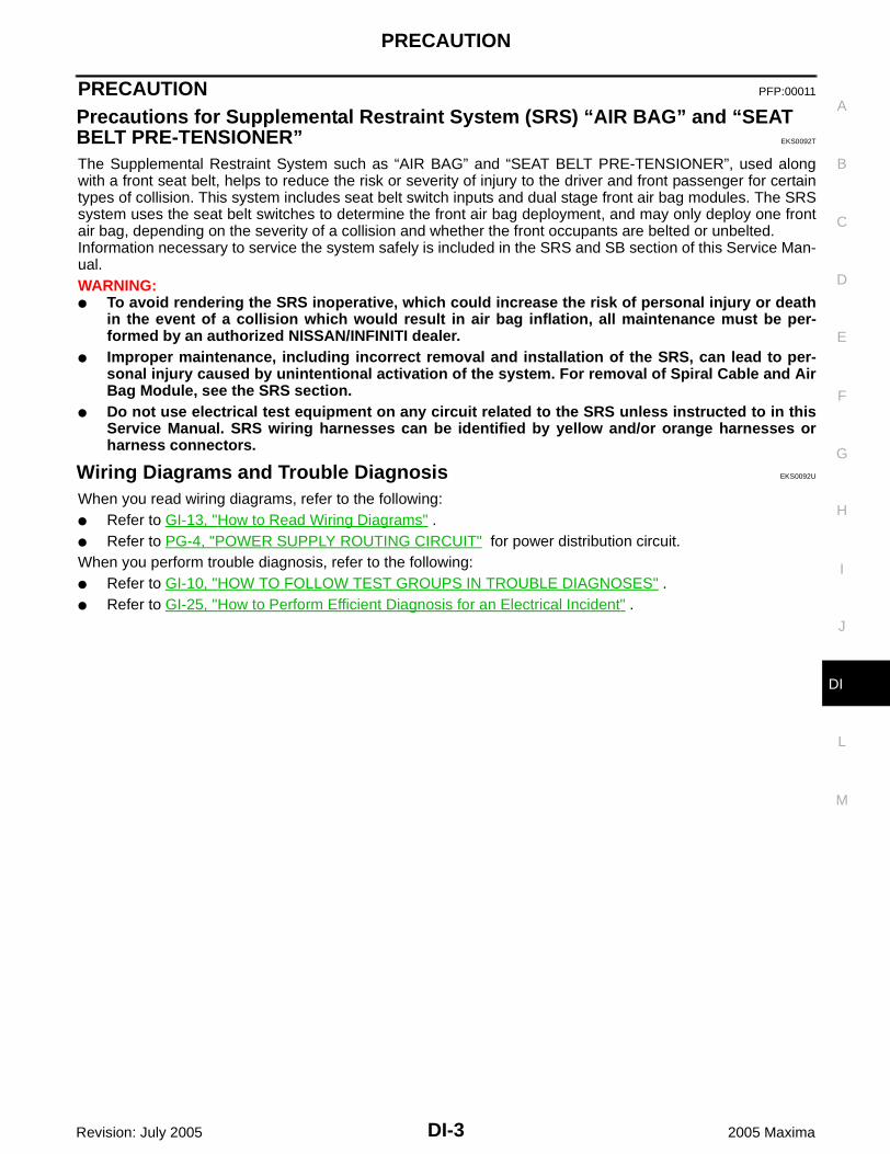
The Supplemental Restraint System such as “AIR BAG” and “SEAT BELT PRE-TENSIONER”, used alongwith a front seat belt, helps to reduce the risk or severity of injury to the driver and front passenger for certaintypes of collision. This system includes seat belt switch inputs and dual stage front air bag modules. The SRSsystem uses the seat belt switches to determine the front air bag deployment, and may only deploy one frontair bag, depending on the severity of a collision and whether the front occupants are belted or unbelted.Information necessary to service the system safely is included in the SRS and SB section of this Service Man-ual.WARNING: To avoid rendering the SRS inoperative, which could increase the risk of personal injury or death
in the event of a collision which would result in air bag inflation, all maintenance must be per-formed by an authorized NISSAN/INFINITI dealer.
Improper maintenance, including incorrect removal and installation of the SRS, can lead to per-sonal injury caused by unintentional activation of the system. For removal of Spiral Cable and AirBag Module, see the SRS section.
Do not use electrical test equipment on any circuit related to the SRS unless instructed to in thisService Manual. SRS wiring harnesses can be identified by yellow and/or orange harnesses orharness connectors.
Wiring Diagrams and Trouble Diagnosis EKS0092U
When you read wiring diagrams, refer to the following: Refer to GI-13, "How to Read Wiring Diagrams" . Refer to PG-4, "POWER SUPPLY ROUTING CIRCUIT" for power distribution circuit.When you perform trouble diagnosis, refer to the following: Refer to GI-10, "HOW TO FOLLOW TEST GROUPS IN TROUBLE DIAGNOSES" . Refer to GI-25, "How to Perform Efficient Diagnosis for an Electrical Incident" .
DI-4
PREPARATION
Revision: July 2005 2005 Maxima
PREPARATION PFP:00002
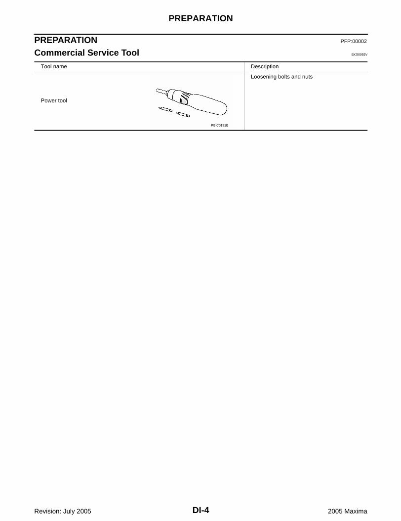
Commercial Service Tool EKS0092V
Tool name Description
Power tool
Loosening bolts and nuts
PBIC0191E

COMBINATION METERS
DI-5
C
D
E
F
G
H
I
J
L
M
A
B
DI
Revision: July 2005 2005 Maxima
COMBINATION METERS PFP:24814
System Description EKS0092W
UNIFIED METER CONTROL UNIT Speedometer, odo/trip meter, tachometer, fuel gauge and water temperature gauge are controlled by the
unified meter control unit, which is built into the combination meter. Unified meter control unit receives sig-nals from unified meter and A/C amp.
Warning lamps and indicator lamps are controlled by signals drawn from the unified meter and A/C amp.,BCM (body control module), and components connected directly to the combination meter.
Digital meter is adopted for odo/trip meter.**The record of the odometer is kept even if the battery cable is disconnected. The record of the trip meteris erased when the battery cable is disconnected.
Odo/trip meter and A/T indicator segments can be checked in diagnosis mode. Meters/gauges can be checked in diagnosis mode.
Illumination control The unified meter control unit outputs the odo/trip meter and A/T indicator lighting when the ignition switch isturned ON. When the lighting switch is turned on, the illumination control switch can be used to adjust thebrightness of the combination meter illumination and the odo/trip meter illumination. When the ignition switchis in the START position, the combination meter dial lighting and illumination control switch lighting are turnedoff. For additional combination meter illumination control information, refer to LT-174, "System Description" .
UNIFIED METER AND A/C AMP.For unified meter and A/C amp. system description information, refer to DI-30, "System Description" .
DI-6
COMBINATION METERS
Revision: July 2005 2005 Maxima
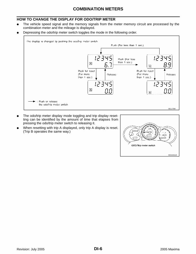
HOW TO CHANGE THE DISPLAY FOR ODO/TRIP METER The vehicle speed signal and the memory signals from the meter memory circuit are processed by the
combination meter and the mileage is displayed. Depressing the odo/trip meter switch toggles the mode in the following order.
The odo/trip meter display mode toggling and trip display reset-ting can be identified by the amount of time that elapses frompressing the odo/trip meter switch to releasing it.
When resetting with trip A displayed, only trip A display is reset.(Trip B operates the same way.)
SEL175W
WKIA0411E

COMBINATION METERS
DI-7
C
D
E
F
G
H
I
J
L
M
A
B
DI
Revision: July 2005 2005 Maxima
POWER SUPPLY AND GROUND CIRCUITPower is supplied at all times through 10A fuse [No.19, located in the fuse block (J/B)] to combination meter terminal 24, and to unified meter and A/C amp. terminal 21.With the ignition switch in the ON or START position, power is supplied through 10A fuse [No.14, located in the fuse block (J/B)] to combination meter terminal 23, and through 10A fuse [No.12, located in the fuse block (J/B)] to unified meter and A/C amp. terminal 22.With the ignition switch in the ON position, power is supplied through 15A fuse [No.10, located in the fuse block (J/B)], and through 15A fuse [No.11, located in the fuse block (J/B)] to unified meter and A/C amp. terminal 46.Ground is supplied to combination meter terminals 10, 11 and 12, and to unified meter and A/C amp. terminals 29 and 30 through body grounds M57, M61 and M79.
WATER TEMPERATURE GAUGEThe water temperature gauge indicates the engine coolant temperature.ECM provides a water temperature signal to unified meter and A/C amp. via CAN communication lines. Uni-fied meter and A/C amp. provides a water temperature signal to combination meter for water temperaturegauge via communication line between unified meter and A/C amp. and combination meter.
TACHOMETERThe tachometer indicates engine speed in revolutions per minute (rpm).ECM provides an engine speed signal to unified meter and A/C amp. via CAN communication lines. Unifiedmeter and A/C amp. provides an engine speed signal to combination meter for tachometer via communicationlines between unified meter and A/C amp. and combination meter.
FUEL GAUGEThe fuel gauge indicates the approximate fuel level in the fuel tank.The fuel gauge is regulated by a variable ground signal supplied from unified meter and A/C amp. terminal 36 through the fuel level sensor unit and fuel pump terminal 5 through the fuel level sensor unit and fuel pump terminal 2 to unified meter and A/C amp. terminal 28 for the fuel gauge.Unified meter and A/C amp. provides a fuel level signal to combination meter for fuel gauge via communica-tion line between unified meter and A/C amp. and combination meter.
SPEEDOMETERABS actuator and electric unit (control unit) provides a vehicle speed signal to the unified meter and A/C amp.via CAN communication lines. After unified meter and A/C amp. receives the vehicle speed signal, it changesthe signal to 8 pulse signal and provides the 8 pulse signal to the combination meter for the speedometer viacommunication line.
DI-8
COMBINATION METERS
Revision: July 2005 2005 Maxima
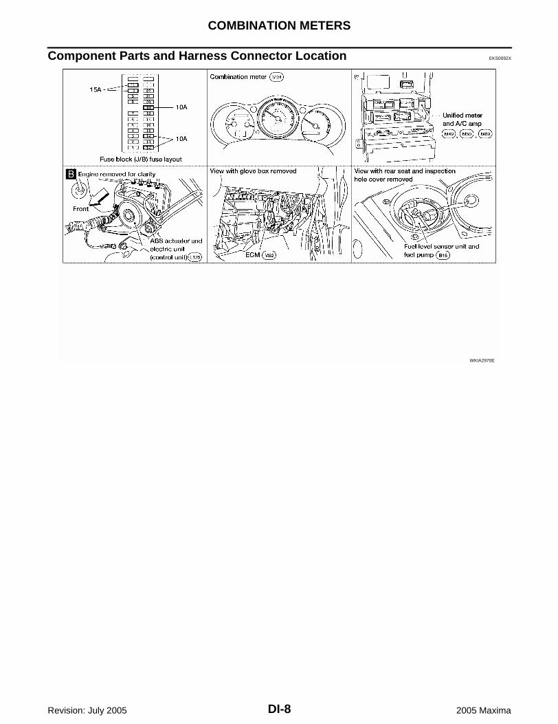
Component Parts and Harness Connector Location EKS0092X
WKIA2970E
COMBINATION METERS
DI-9
C
D
E
F
G
H
I
J
L
M
A
B
DI
Revision: July 2005 2005 Maxima
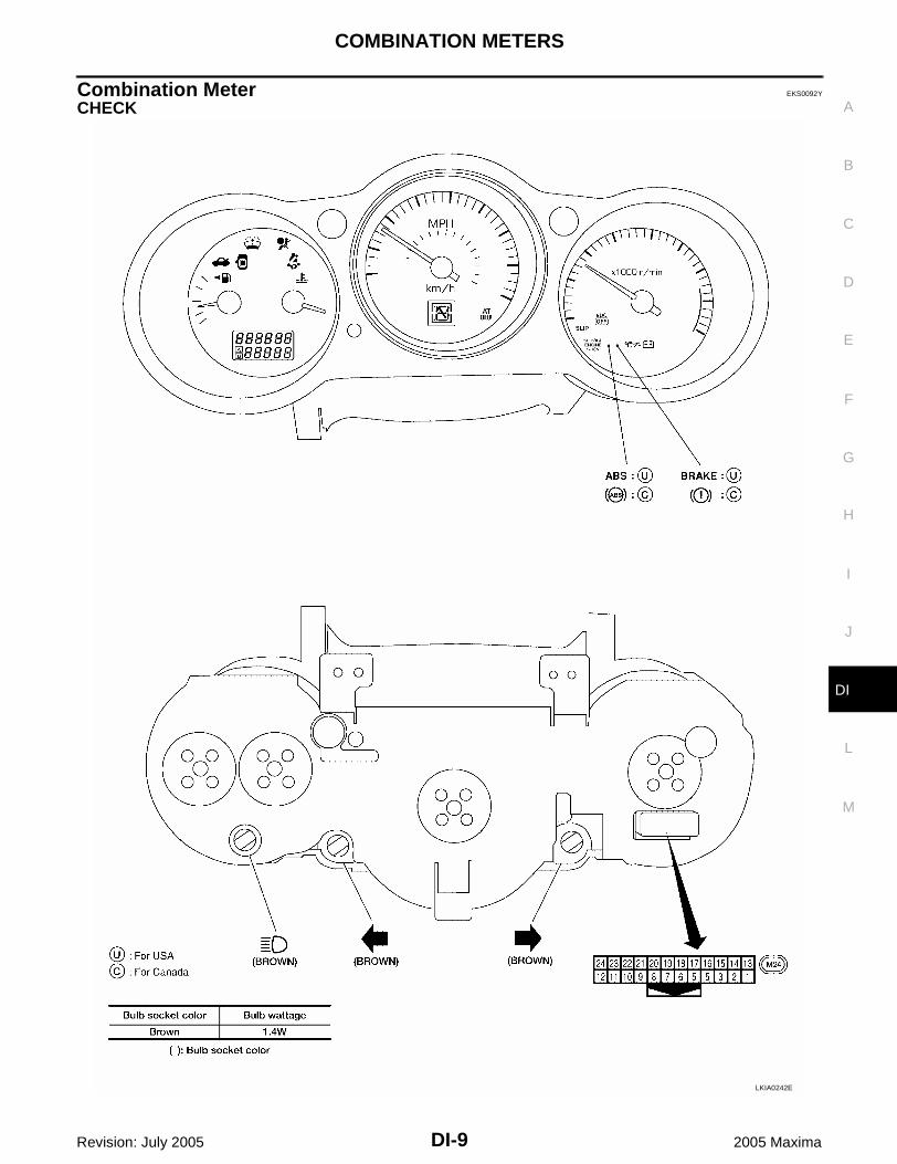
Combination Meter EKS0092Y
CHECK
LKIA0242E
DI-10
COMBINATION METERS
Revision: July 2005 2005 Maxima
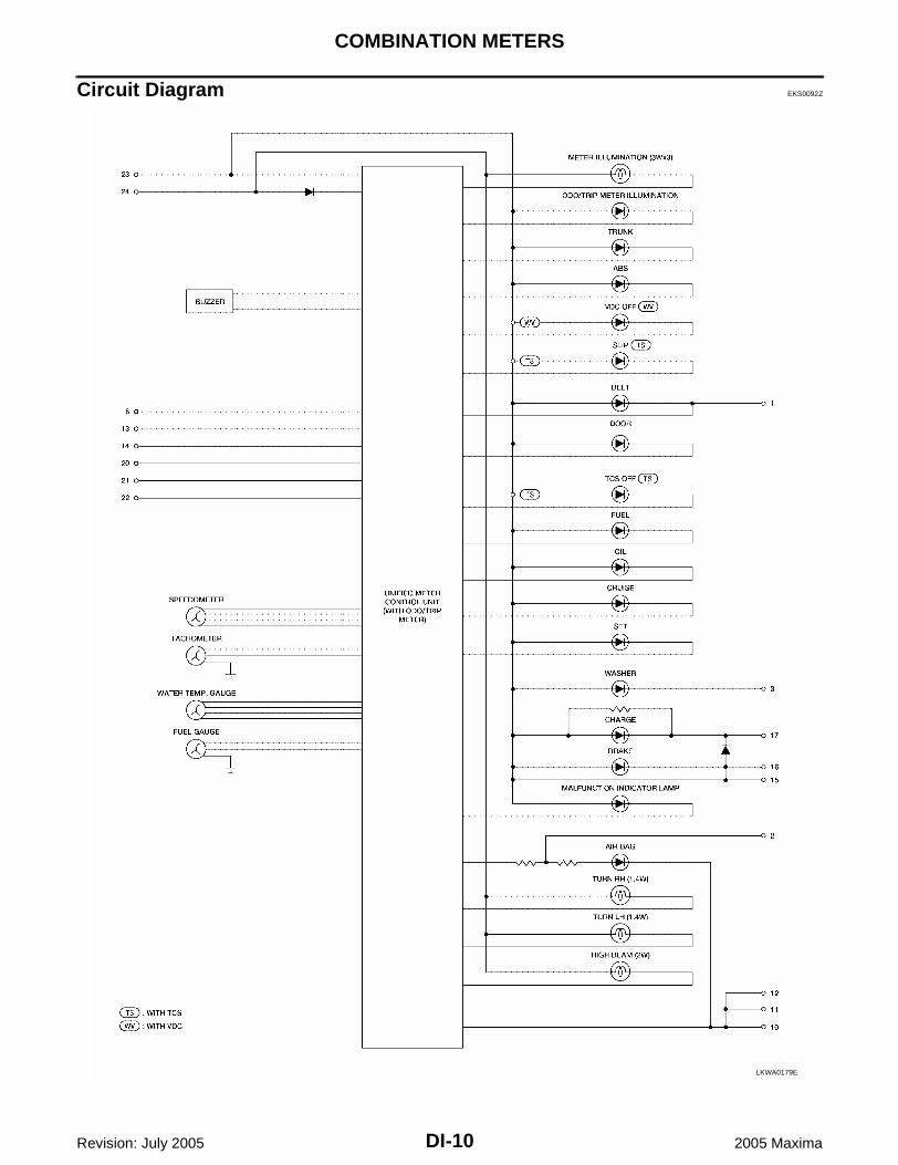
Circuit Diagram EKS0092Z
LKWA0179E

COMBINATION METERS
DI-11
C
D
E
F
G
H
I
J
L
M
A
B
DI
Revision: July 2005 2005 Maxima
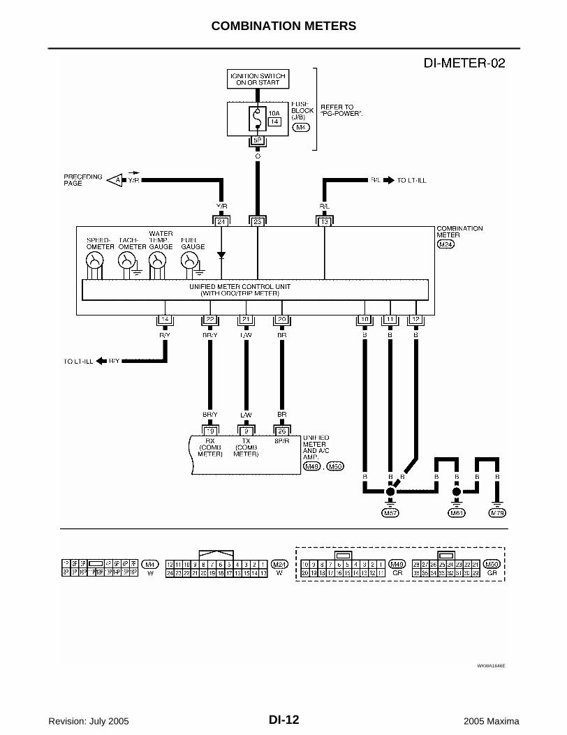
Wiring Diagram — METER — EKS00930
WKWA1645E
DI-12
COMBINATION METERS
Revision: July 2005 2005 Maxima
WKWA1646E

COMBINATION METERS
DI-13
C
D
E
F
G
H
I
J
L
M
A
B
DI
Revision: July 2005 2005 Maxima
Terminals and Reference Value for Combination Meter EKS00931
Terminal No.
Wire color
Item
ConditionReference value (V)
(Approx.)Ignition switch
Operation or condition
10 B Ground ON — 0
11 B Ground ON — 0
12 B Ground ON — 0
13 R/LIllumination control switch (+)
— —Refer to LT-175, "ILLUMINATION OPERATION BY LIGHTING SWITCH" .
14 R/Y Illumination signal ONLighting switch ON
<e.g.> When brightness level is about midway.
Lighting switch OFF 0
20 BRVehicle speed signal(8-pulse)
ONSpeedometer operated[When vehicle speed is approx. 40 km/h (25 MPH)]
21 L/WRX communication line (From unified meter and A/C amp.)
ON —
22 BR/YTX communication line (To unified meter and A/C amp.)
ON —
23 OIgnition switch ON or START
ON — Battery voltage
24 Y/R Battery power supply OFF — Battery voltage
SKIA5872E
PKIA1935E
SKIA3362E
SKIA3361E

DI-14
COMBINATION METERS
Revision: July 2005 2005 Maxima
Terminals and Reference Value for Unified Meter and A/C Amp. EKS00932
Terminal No.
Wire color
Item
ConditionReference value (V)
(Approx.)Ignition switch
Operation or condition
1 L CAN-H — — —
9 L/WTX communication line (To combination meter)
ON —
11 P CAN-L — — —
19 BR/YRX communication line (From combination meter)
ON —
21 Y/R Battery power supply OFF — Battery voltage
22 GIgnition switch ON or START
ON — Battery voltage
26 BRVehicle speed signal(8-pulse)
ONSpeedometer operated[When vehicle speed is approx. 40 km/h (25 MPH)]
28 L Fuel level sensor signal — —Refer to DI-29, "FUEL LEVEL SEN-SOR UNIT CHECK" .
29 B Ground (For power) ON — 0
30 B Ground ON — 0
36 B/RFuel level sensor signal ground
— — —
46 W/L Ignition switch ON ON — Battery voltage
SKIA3362E
SKIA3361E
PKIA1935E

COMBINATION METERS
DI-15
C
D
E
F
G
H
I
J
L
M
A
B
DI
Revision: July 2005 2005 Maxima
Meter/Gauge Operation and Odo/Trip Meter EKS00933
SELF-DIAGNOSIS FUNCTION Odo/trip meter segment and A/T indicator segment operation can be checked in self-diagnosis mode. Meters/gauges can be checked in self-diagnosis mode.
HOW TO ALTERNATE DIAGNOSIS MODE1. Turn ignition switch ON, and switch the odo/trip meter to “trip A” or “trip B”.
NOTE:If the diagnosis function is activated with the trip meter A displayed, the mileage on the trip meter A willindicate 0000.0 miles, but the actual trip mileage will be retained. (Trip B operates the same way.)
2. Turn ignition switch OFF.3. While pushing the odo/trip meter switch, turn ignition switch ON
again.4. Make sure the trip meter displays “0000.0”.5. Push the odo/trip meter switch at least 3 times within 5 seconds.6. All the segments on the odo/trip meter and A/T indicator illumi-
nate, and simultaneously the low-fuel warning lamp indicatorilluminates. At this time, the unified meter control unit is turnedto diagnosis mode.NOTE:If any of the segments are not displayed, replace the combina-tion meter.
7. Push the odo/trip meter switch. Each meter/gauge should indi-cate as shown in the figure while pushing odo/trip meter switch.(At this time, the low-fuel warning lamp goes off.)
CONSULT-II Function EKS00934
Refer to DI-33, "CONSULT-II Function (METER A/C AMP)" in “UNIFIED METER AND A/C AMP”.
WKIA0411E
WKIA0412E
LKIA0243E

DI-16
COMBINATION METERS
Revision: July 2005 2005 Maxima
How to Proceed With Trouble Diagnosis EKS00935
1. Confirm the symptom or customer complaint.2. Perform diagnosis according to diagnosis flow. Refer to DI-16, "Diagnosis Flow" .3. According to the symptom chart, repair or replace the cause of the symptom.4. Does the meter operate normally? If so, go to 5. If not, go to 2.5. Inspection End.
Diagnosis Flow EKS00936
1. CHECK SELF-DIAGNOSTIC RESULTS OF UNIFIED METER AND A/C AMP.
1. Start engine.2. Select “METER A/C AMP” on CONSULT-II, and perform self-diagnosis of unified meter and A/C amp.
Refer to DI-33, "CONSULT-II Function (METER A/C AMP)" .3. After erasing the self-diagnosis result, perform self-diagnosis again.Self-diagnostic results contentNo malfunction detected>> GO TO 2.Malfunction detected>> Go to DI-19, "Symptom Chart 2" .
2. CHECK WARNING LAMP ILLUMINATION
1. Turn ignition switch ON.2. Make sure warning lamps (such as malfunction indicator lamp and oil pressure warning lamp) illuminate.Do warning lamps illuminate?YES >> GO TO 3.NO >> Check ignition power supply system of combination meter. Refer to DI-17, "Power Supply and
Ground Circuit Inspection" .
3. CHECK SELF-DIAGNOSIS OPERATION OF COMBINATION METER
Perform combination meter self-diagnosis. Refer to DI-15, "SELF-DIAGNOSIS FUNCTION" .Does self-diagnosis function operate?YES >> GO TO 4.NO >> Check combination meter power supply and ground circuit. Refer to DI-17, "Power Supply and
Ground Circuit Inspection" .
4. CHECK ODO/TRIP METER OPERATION
Check segment display status of odo/trip meter.Is the display normal?YES >> GO TO 5.NO >> Replace the combination meter. Refer to DI-29,
"Removal and Installation of Combination Meter" .
SEL176W

COMBINATION METERS
DI-17
C
D
E
F
G
H
I
J
L
M
A
B
DI
Revision: July 2005 2005 Maxima
5. CHECK LOW-FUEL WARNING LAMP ILLUMINATION CONFIRMATION
During low-fuel warning lamp check, confirm illumination of low-fuel warning lamp.
OK or NGOK >> GO TO 6.NG >> Replace the combination meter. Refer to DI-29, "Removal and Installation of Combination Meter" .
6. CHECK COMBINATION METER CIRCUIT
Check indication of each meter/gauge in self-diagnosis mode.OK or NGOK >> Go to DI-19, "Symptom Chart 1" .NG >> Replace the combination meter. Refer to DI-29,
"Removal and Installation of Combination Meter" .
Power Supply and Ground Circuit Inspection EKS00937
1. CHECK FUSE
Check for blown combination meter and unified meter and A/C amp. fuses.
Refer to DI-11, "Wiring Diagram — METER —" .
OK or NGOK >> GO TO 2.NG >> If fuse is blown, be sure to eliminate cause of malfunction before installing new fuse. Refer to PG-
4, "POWER SUPPLY ROUTING CIRCUIT" .
Condition of odo/trip meter switch
Low-fuel warning lamp
Pushed Does not illuminate.
Released Illuminates.
LKIA0243E
Unit Power source Fuse No.
Combination meter Battery 19
Unified meter and A/C amp.
Combination meter Ignition switch ON or START 14
Unified meter and A/C amp. Ignition switch ON or START 12
Unified meter and A/C amp. Ignition switch ON 10, 11

DI-18
COMBINATION METERS
Revision: July 2005 2005 Maxima
2. CHECK POWER SUPPLY CIRCUIT
1. Disconnect combination meter connector M24 and unified meterand A/C amp. connectors M50 and M89.
2. Check voltage between combination meter harness connectorterminals and ground.
3. Check voltage between unified meter and A/C amp. harnessconnector terminals and ground.
OK or NGOK >> GO TO 3.NG >> Check the following.
Harness for open or short between combination meter and fuse Harness for open or short between unified meter and A/C amp. and fuse
Terminals Ignition switch position
(+)
(–) OFF ACC ONConnector
Terminal(Wire color)
M24
24 (Y/R)
Ground
Battery voltage
Battery voltage
Battery voltage
23 (O) 0V 0VBattery voltage
WKIA0413E
Terminals Ignition switch position
(+)
(–) OFF ACC ONConnector
Terminal(Wire color)
M50
21 (Y/R)
Ground
Battery voltage
Battery voltage
Battery voltage
22 (G) 0V 0VBattery voltage
M89 46 (W/L) 0V 0VBattery voltage
PKIA1998E
COMBINATION METERS
DI-19
C
D
E
F
G
H
I
J
L
M
A
B
DI
Revision: July 2005 2005 Maxima
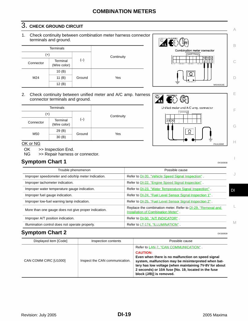
3. CHECK GROUND CIRCUIT
1. Check continuity between combination meter harness connectorterminals and ground.
2. Check continuity between unified meter and A/C amp. harnessconnector terminals and ground.
OK or NGOK >> Inspection End.NG >> Repair harness or connector.
Symptom Chart 1 EKS00938
Symptom Chart 2 EKS00939
Terminals
Continuity(+)
(–)Connector
Terminal(Wire color)
M24
10 (B)
Ground Yes11 (B)
12 (B) WKIA0414E
Terminals
Continuity(+)
(–)Connector
Terminal(Wire color)
M5029 (B)
Ground Yes30 (B)
PKIA1999E
Trouble phenomenon Possible cause
Improper speedometer and odo/trip meter Indication. Refer to DI-20, "Vehicle Speed Signal Inspection" .
Improper tachometer indication. Refer to DI-22, "Engine Speed Signal Inspection" .
Improper water temperature gauge indication. Refer to DI-23, "Water Temperature Signal Inspection" .
Improper fuel gauge indication. Refer to DI-24, "Fuel Level Sensor Signal Inspection 1" .
Improper low-fuel warning lamp indication. Refer to DI-25, "Fuel Level Sensor Signal Inspection 2" .
More than one gauge does not give proper indication.Replace the combination meter. Refer to DI-29, "Removal and Installation of Combination Meter" .
Improper A/T position indication. Refer to DI-50, "A/T INDICATOR" .
Illumination control does not operate properly. Refer to LT-174, "ILLUMINATION" .
Displayed item [Code] Inspection contents Possible cause
CAN COMM CIRC [U1000] Inspect the CAN communication.
Refer to LAN-7, "CAN COMMUNICATION" .
CAUTION:Even when there is no malfunction on speed signal system, malfunction may be misinterpreted when bat-tery has low voltage (when maintaining 7V-8V for about 2 seconds) or 10A fuse [No. 19, located in the fuse block (J/B)] is removed.

DI-20
COMBINATION METERS
Revision: July 2005 2005 Maxima
Vehicle Speed Signal Inspection EKS0093A
1. CHECK CONTINUITY BETWEEN COMBINATION METER AND UNIFIED METER AND A/C AMP.
1. Disconnect combination meter connector M24 and unified meterand A/C amp. connector M50.
2. Check continuity between combination meter harness connectorM24 terminal 20 (BR) and unified meter and A/C amp. harnessconnector M50 terminal 26 (BR).
3. Check continuity between combination meter harness connectorM24 terminal 20 (BR) and ground.
OK or NGOK >> GO TO 2.NG >> Repair harness or connector.
2. CHECK VOLTAGE OF COMBINATION METER
1. Connect combination meter connector.2. Turn ignition switch ON.3. Check voltage between combination meter harness connector
M24 terminal 20 (BR) and ground.
OK or NGOK >> GO TO 3.NG >> Replace combination meter, refer to DI-29, "Removal
and Installation of Combination Meter" .
METER COMM CIRC [B2202]Inspect the communication line between combination meter and unified meter and A/C amp.
Refer to DI-25, "Communication Line Inspection" .
VEHICLE SPEED CIRC [B2205]Inspect the vehicle speed input signal.
Perform the ABS actuator and electric unit (control unit) self-diagnosis.
With traction control but without VDC system, refer to BRC-66, "SELF-DIAGNOSIS" .
Without traction control system, refer to BRC-25, "SELF-DIAGNOSIS" .
With VDC system, refer to BRC-112, "SELF-DIAGNO-SIS" .
CAUTION:Even when there is no malfunction on speed signal system, malfunction may be misinterpreted when bat-tery has low voltage (when maintaining 7V-8V for about 2 seconds).
Displayed item [Code] Inspection contents Possible cause
Continuity should exist.
Continuity should not exist.WKIA0416E
Battery voltage should exist.
WKIA0957E

COMBINATION METERS
DI-21
C
D
E
F
G
H
I
J
L
M
A
B
DI
Revision: July 2005 2005 Maxima
3. CHECK UNIFIED METER AND A/C AMP. OUTPUT SIGNAL
1. Turn ignition switch OFF.2. Connect unified meter and A/C amp. connector.3. Check voltage signal between combination meter harness con-
nector M24 terminal 20 (BR) and ground with simple oscillo-scope of CONSULT-II.
OK or NGOK >> Replace the combination meter. Refer to DI-29, "Removal and Installation of Combination Meter" .NG >> GO TO 4.
4. CHECK ABS ACTUATOR AND ELECTRIC UNIT (CONTROL UNIT) SELF-DIAGNOSIS
Perform the ABS actuator and electric unit (control unit) self-diagnosis. With traction control but without VDC system, refer to BRC-66, "SELF-DIAGNOSIS" . Without traction control or VDC system, refer to BRC-25, "SELF-DIAGNOSIS" . With VDC system, refer to BRC-112, "SELF-DIAGNOSIS" .OK or NGOK >> Replace the unified meter and A/C amp. Refer to DI-36, "Removal and Installation of Unified
Meter and A/C Amp." .NG >> Check the applicable parts.
20 (BR) - Ground:WKIA3342E
PKIA1935E
DI-22
COMBINATION METERS
Revision: July 2005 2005 Maxima
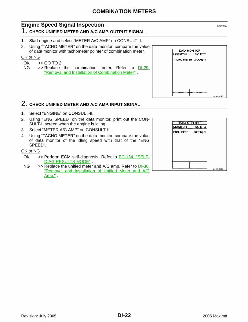
Engine Speed Signal Inspection EKS0093B
1. CHECK UNIFIED METER AND A/C AMP. OUTPUT SIGNAL
1. Start engine and select “METER A/C AMP” on CONSULT-II.2. Using “TACHO METER” on the data monitor, compare the value
of data monitor with tachometer pointer of combination meter. OK or NGOK >> GO TO 2.NG >> Replace the combination meter. Refer to DI-29,
"Removal and Installation of Combination Meter" .
2. CHECK UNIFIED METER AND A/C AMP. INPUT SIGNAL
1. Select “ENGINE” on CONSULT-II.2. Using “ENG SPEED” on the data monitor, print out the CON-
SULT-II screen when the engine is idling.3. Select “METER A/C AMP” on CONSULT-II.4. Using “TACHO METER” on the data monitor, compare the value
of data monitor of the idling speed with that of the “ENGSPEED”.
OK or NGOK >> Perform ECM self-diagnosis. Refer to EC-134, "SELF-
DIAG RESULTS MODE" .NG >> Replace the unified meter and A/C amp. Refer to DI-36,
"Removal and Installation of Unified Meter and A/CAmp." .
LKIA0329E
LKIA0330E

COMBINATION METERS
DI-23
C
D
E
F
G
H
I
J
L
M
A
B
DI
Revision: July 2005 2005 Maxima
Water Temperature Signal Inspection EKS0093C
1. CHECK UNIFIED METER AND A/C AMP. OUTPUT SIGNAL
1. Start engine and select “METER A/C AMP” on CONSULT-II.2. Using “W TEMP METER” on the data monitor, compare the
value of data monitor with water temperature gauge pointer ofcombination meter.
OK or NGOK >> GO TO 2.NG >> Replace the combination meter. Refer to DI-29, "Removal and Installation of Combination Meter" .
2. CHECK UNIFIED METER AND A/C AMP. INPUT SIGNAL
1. Select “ENGINE” on CONSULT-II.2. Using “COOLAN TEMP/S” on the data monitor, print out the
CONSULT-II screen.3. Select “METER A/C AMP” on CONSULT-II.4. Using “W TEMP METER” on the data monitor, compare the
value of data monitor with that of the “COOLAN TEMP/S”.OK or NGOK >> Perform ECM self-diagnosis. Refer to EC-134, "SELF-
DIAG RESULTS MODE" .NG >> Replace the unified meter and A/C amp. Refer to DI-36,
"Removal and Installation of Unified Meter and A/CAmp." .
Water temperature gauge pointerReference value of data monitor °C (°F)
(Approx.)
Hot 130 (266)
Middle 70-105 (158-221)
Cold 50 (122)
LKIA0331E
LKIA0332E
DI-24
COMBINATION METERS
Revision: July 2005 2005 Maxima
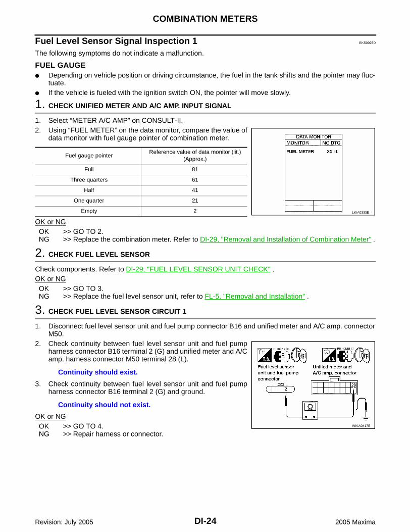
Fuel Level Sensor Signal Inspection 1 EKS0093D
The following symptoms do not indicate a malfunction.
FUEL GAUGE Depending on vehicle position or driving circumstance, the fuel in the tank shifts and the pointer may fluc-
tuate. If the vehicle is fueled with the ignition switch ON, the pointer will move slowly.
1. CHECK UNIFIED METER AND A/C AMP. INPUT SIGNAL
1. Select “METER A/C AMP” on CONSULT-II.2. Using “FUEL METER” on the data monitor, compare the value of
data monitor with fuel gauge pointer of combination meter.
OK or NGOK >> GO TO 2.NG >> Replace the combination meter. Refer to DI-29, "Removal and Installation of Combination Meter" .
2. CHECK FUEL LEVEL SENSOR
Check components. Refer to DI-29, "FUEL LEVEL SENSOR UNIT CHECK" .OK or NGOK >> GO TO 3.NG >> Replace the fuel level sensor unit, refer to FL-5, "Removal and Installation" .
3. CHECK FUEL LEVEL SENSOR CIRCUIT 1
1. Disconnect fuel level sensor unit and fuel pump connector B16 and unified meter and A/C amp. connectorM50.
2. Check continuity between fuel level sensor unit and fuel pumpharness connector B16 terminal 2 (G) and unified meter and A/Camp. harness connector M50 terminal 28 (L).
3. Check continuity between fuel level sensor unit and fuel pumpharness connector B16 terminal 2 (G) and ground.
OK or NGOK >> GO TO 4.NG >> Repair harness or connector.
Fuel gauge pointerReference value of data monitor (lit.)
(Approx.)
Full 81
Three quarters 61
Half 41
One quarter 21
Empty 2 LKIA0333E
Continuity should exist.
Continuity should not exist.
WKIA0417E
COMBINATION METERS
DI-25
C
D
E
F
G
H
I
J
L
M
A
B
DI
Revision: July 2005 2005 Maxima
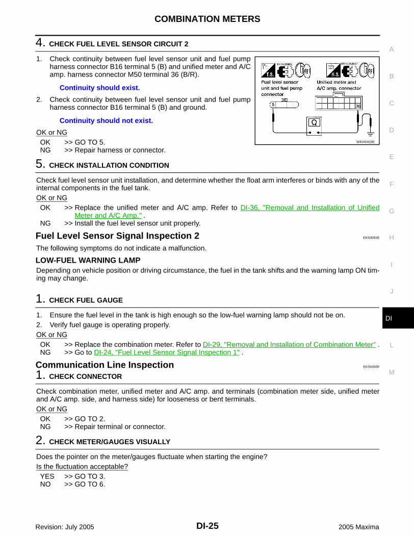
4. CHECK FUEL LEVEL SENSOR CIRCUIT 2
1. Check continuity between fuel level sensor unit and fuel pumpharness connector B16 terminal 5 (B) and unified meter and A/Camp. harness connector M50 terminal 36 (B/R).
2. Check continuity between fuel level sensor unit and fuel pumpharness connector B16 terminal 5 (B) and ground.
OK or NGOK >> GO TO 5.NG >> Repair harness or connector.
5. CHECK INSTALLATION CONDITION
Check fuel level sensor unit installation, and determine whether the float arm interferes or binds with any of theinternal components in the fuel tank.OK or NGOK >> Replace the unified meter and A/C amp. Refer to DI-36, "Removal and Installation of Unified
Meter and A/C Amp." .NG >> Install the fuel level sensor unit properly.
Fuel Level Sensor Signal Inspection 2 EKS0093E
The following symptoms do not indicate a malfunction.
LOW-FUEL WARNING LAMPDepending on vehicle position or driving circumstance, the fuel in the tank shifts and the warning lamp ON tim-ing may change.
1. CHECK FUEL GAUGE
1. Ensure the fuel level in the tank is high enough so the low-fuel warning lamp should not be on.2. Verify fuel gauge is operating properly.OK or NGOK >> Replace the combination meter. Refer to DI-29, "Removal and Installation of Combination Meter" .NG >> Go to DI-24, "Fuel Level Sensor Signal Inspection 1" .
Communication Line Inspection EKS0093F
1. CHECK CONNECTOR
Check combination meter, unified meter and A/C amp. and terminals (combination meter side, unified meterand A/C amp. side, and harness side) for looseness or bent terminals.OK or NGOK >> GO TO 2.NG >> Repair terminal or connector.
2. CHECK METER/GAUGES VISUALLY
Does the pointer on the meter/gauges fluctuate when starting the engine?Is the fluctuation acceptable?YES >> GO TO 3.NO >> GO TO 6.
Continuity should exist.
Continuity should not exist.
WKIA0418E
DI-26
COMBINATION METERS
Revision: July 2005 2005 Maxima
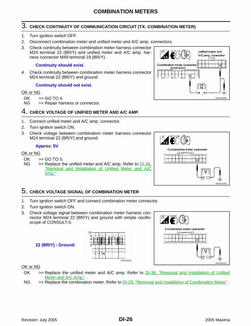
3. CHECK CONTINUITY OF COMMUNICATION CIRCUIT (TX: COMBINATION METER)
1. Turn ignition switch OFF.2. Disconnect combination meter and unified meter and A/C amp. connectors.3. Check continuity between combination meter harness connector
M24 terminal 22 (BR/Y) and unified meter and A/C amp. har-ness connector M49 terminal 19 (BR/Y).
4. Check continuity between combination meter harness connectorM24 terminal 22 (BR/Y) and ground.
OK or NGOK >> GO TO 4.NG >> Repair harness or connector.
4. CHECK VOLTAGE OF UNIFIED METER AND A/C AMP.
1. Connect unified meter and A/C amp. connector.2. Turn ignition switch ON.3. Check voltage between combination meter harness connector
M24 terminal 22 (BR/Y) and ground.
OK or NGOK >> GO TO 5.NG >> Replace the unified meter and A/C amp. Refer to DI-36,
"Removal and Installation of Unified Meter and A/CAmp." .
5. CHECK VOLTAGE SIGNAL OF COMBINATION METER
1. Turn ignition switch OFF and connect combination meter connector.2. Turn ignition switch ON.3. Check voltage signal between combination meter harness con-
nector M24 terminal 22 (BR/Y) and ground with simple oscillo-scope of CONSULT-II.
OK or NGOK >> Replace the unified meter and A/C amp. Refer to DI-36, "Removal and Installation of Unified
Meter and A/C Amp." .NG >> Replace the combination meter. Refer to DI-29, "Removal and Installation of Combination Meter" .
Continuity should exist.
Continuity should not exist.
WKIA0419E
Approx. 5V
WKIA0420E
22 (BR/Y) - Ground:
WKIA0421ESKIA3361E
COMBINATION METERS
DI-27
C
D
E
F
G
H
I
J
L
M
A
B
DI
Revision: July 2005 2005 Maxima
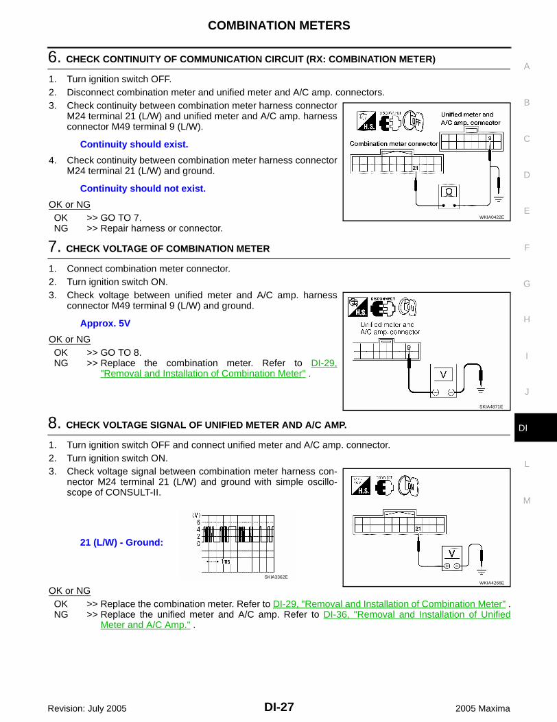
6. CHECK CONTINUITY OF COMMUNICATION CIRCUIT (RX: COMBINATION METER)
1. Turn ignition switch OFF.2. Disconnect combination meter and unified meter and A/C amp. connectors.3. Check continuity between combination meter harness connector
M24 terminal 21 (L/W) and unified meter and A/C amp. harnessconnector M49 terminal 9 (L/W).
4. Check continuity between combination meter harness connectorM24 terminal 21 (L/W) and ground.
OK or NGOK >> GO TO 7.NG >> Repair harness or connector.
7. CHECK VOLTAGE OF COMBINATION METER
1. Connect combination meter connector.2. Turn ignition switch ON.3. Check voltage between unified meter and A/C amp. harness
connector M49 terminal 9 (L/W) and ground.
OK or NGOK >> GO TO 8.NG >> Replace the combination meter. Refer to DI-29,
"Removal and Installation of Combination Meter" .
8. CHECK VOLTAGE SIGNAL OF UNIFIED METER AND A/C AMP.
1. Turn ignition switch OFF and connect unified meter and A/C amp. connector.2. Turn ignition switch ON.3. Check voltage signal between combination meter harness con-
nector M24 terminal 21 (L/W) and ground with simple oscillo-scope of CONSULT-II.
OK or NGOK >> Replace the combination meter. Refer to DI-29, "Removal and Installation of Combination Meter" .NG >> Replace the unified meter and A/C amp. Refer to DI-36, "Removal and Installation of Unified
Meter and A/C Amp." .
Continuity should exist.
Continuity should not exist.
WKIA0422E
Approx. 5V
SKIA4871E
21 (L/W) - Ground:
WKIA4266ESKIA3362E
DI-28
COMBINATION METERS
Revision: July 2005 2005 Maxima
Fuel Gauge Pointer Fluctuates, Indicates Wrong Value, or Varies EKS0093G
1. CHECK FUEL GAUGE FLUCTUATION
Test drive vehicle to see if gauge fluctuates only during driving or just before or just after stopping.Does the indication value vary only during driving or just before or just after stopping?YES >> The pointer fluctuation may be caused by fuel level change in the fuel tank. Condition is normal.NO >> Ask the customer about the situation when the symptom occurs in detail, and perform the trouble
diagnosis.
Fuel Gauge Does Not Move to Full-position EKS0093H
1. QUESTION 1
Does it take a long time for the pointer to move to full-position?YES or NOYES >> GO TO 2.NO >> GO TO 3.
2. QUESTION 2
Was the vehicle fueled with the ignition switch ON?YES or NOYES >> Be sure to fuel the vehicle with the ignition switch OFF. Otherwise, it will take a long time for the
pointer to move to full-position because of the characteristic of the fuel gauge.NO >> GO TO 3.
3. QUESTION 3
Is the vehicle parked on an incline?YES or NOYES >> Check the fuel level indication with vehicle on a level surface.NO >> GO TO 4.
4. QUESTION 4
During driving, does the fuel gauge pointer move gradually toward empty-position?YES or NOYES >> Check the fuel level sensor unit. Refer to DI-29, "FUEL LEVEL SENSOR UNIT CHECK" .NO >> Check fuel level sensor unit installation, and determine whether the float arm interferes or binds
with any of the internal components in the fuel tank.
COMBINATION METERS
DI-29
C
D
E
F
G
H
I
J
L
M
A
B
DI
Revision: July 2005 2005 Maxima
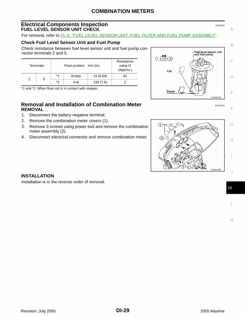
Electrical Components Inspection EKS0093I
FUEL LEVEL SENSOR UNIT CHECKFor removal, refer to FL-5, "FUEL LEVEL SENSOR UNIT, FUEL FILTER AND FUEL PUMP ASSEMBLY" .
Check Fuel Level Sensor Unit and Fuel PumpCheck resistance between fuel level sensor unit and fuel pump con-nector terminals 2 and 5.
*1 and *2: When float rod is in contact with stopper.
Removal and Installation of Combination Meter EKS0093J
REMOVAL1. Disconnect the battery negative terminal.2. Remove the combination meter covers (1).3. Remove 3 screws using power tool and remove the combination
meter assembly (2).4. Disconnect electrical connector and remove combination meter.
INSTALLATIONInstallation is in the reverse order of removal.
Terminals Float position mm (in)Resistance
value Ω(Approx.)
2 5*1 Empty 15 (0.59) 81
*2 Full 193 (7.6) 2
LKIA0244E
WIIA0185E

DI-30
UNIFIED METER AND A/C AMP
Revision: July 2005 2005 Maxima
UNIFIED METER AND A/C AMP PFP:27760
System Description EKS0093K
For the unified meter and A/C amp., the signal line (CAN-H, CAN-L and fuel level sensor) required forcontrolling the combination meter are integrated in the A/C auto amp.
In addition to providing input to the A/C auto amp., signals required for combination meter operation arereceived from various components either directly, or via CAN communication. These signals are sent tothe combination meter using the TX and RX communication lines between the combination meter and uni-fied meter and A/C amp. For information regarding A/C control, refer to ATC-21, "AIR CONDITIONERCONTROL" in ATC section.
The signals required for the distance to empty (DTE) display are centralized in the unified meter and A/Camp., converted into data, and sent to the display control unit using CAN communication.
Other input signals are also sent to the ECM, TCM, display control unit and BCM using CAN communica-tion.
CONSULT-II functions (self-diagnostic results and data monitor) are used to identify errors in the commu-nication lines connected to the unified meter and A/C amp., and to monitor the status of signals receivedby the combination meter from the unified meter and A/C amp.
INPUT/OUTPUT SIGNALSBetween Unified Meter and A/C Amp. and Combination Meter
Unit Input Output
Unified meter and A/C amp.
Seat belt buckle switch signal (Driver's side)
Parking brake signal
Refuel status signal
Low-fuel warning lamp condition signal
Combination meter receiver error signal
Delivery destination data signal
Combination meter specifications signal
Vehicle speed signal (8-pulse)
Engine speed signal
Engine coolant temperature signal
Fuel level sensor signal (resistance value)
Malfunction indicator signal
ABS warning lamp signal
Brake warning lamp signal
Turn indicator signal
High beam request signal
TCS OFF indicator lamp signal
VDC OFF indicator lamp signal
SLIP indicator lamp signal
A/T position indicator signal
Manual mode gear position signal
Door switch signal
Oil pressure switch signal
Buzzer output signal

UNIFIED METER AND A/C AMP
DI-31
C
D
E
F
G
H
I
J
L
M
A
B
DI
Revision: July 2005 2005 Maxima
FAIL-SAFESolution When Communication Error Between the Unified Meter & A/C Amp. and the Combi-nation Meter
CAN Communication System Description EKS0093L
Refer to LAN-7, "CAN COMMUNICATION" .
Function Specifications
Speedometer
Reset to zero by suspending communication. Tachometer
Fuel gauge
Water temperature gauge
Illumination control Combination meter illumination When suspending communication, change to nighttime mode.
Odo/trip meter Integrate in response to 8-pulse input.
A/T indicator The display turns off by suspending communication.
Warning buzzer The warning buzzer turns off by suspending communication.
Warning lamp/indicator lamp
ABS warning lamp
The lamp turns on by suspending communication.
VDC OFF indicator
TCS OFF indicator
SLIP indicator
Brake warning lamp
Door warning lamp
The lamp turns off by suspending communication.
ASCD SET indicator lamp
ASCD CRUISE indicator lamp
Oil pressure warning lamp
Turn signal indicator
Malfunction indicator lamp
A/T indicator lamp
High beam indicator
DI-32
UNIFIED METER AND A/C AMP
Revision: July 2005 2005 Maxima
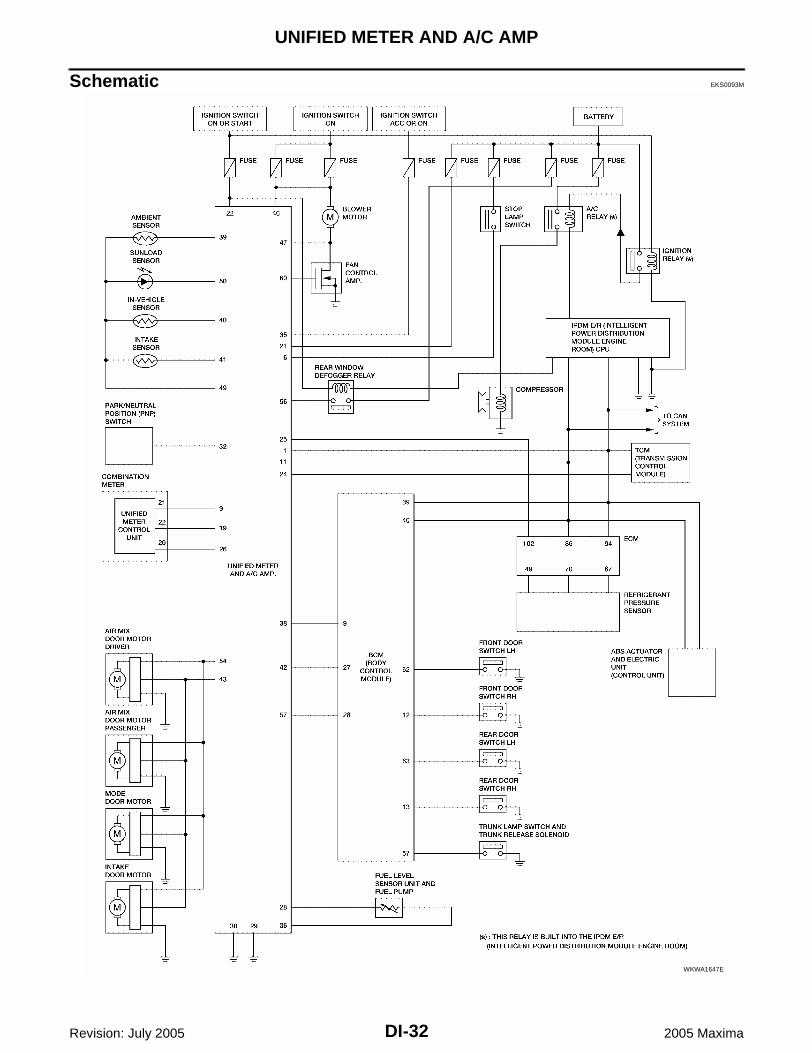
Schematic EKS0093M
WKWA1647E
UNIFIED METER AND A/C AMP
DI-33
C
D
E
F
G
H
I
J
L
M
A
B
DI
Revision: July 2005 2005 Maxima
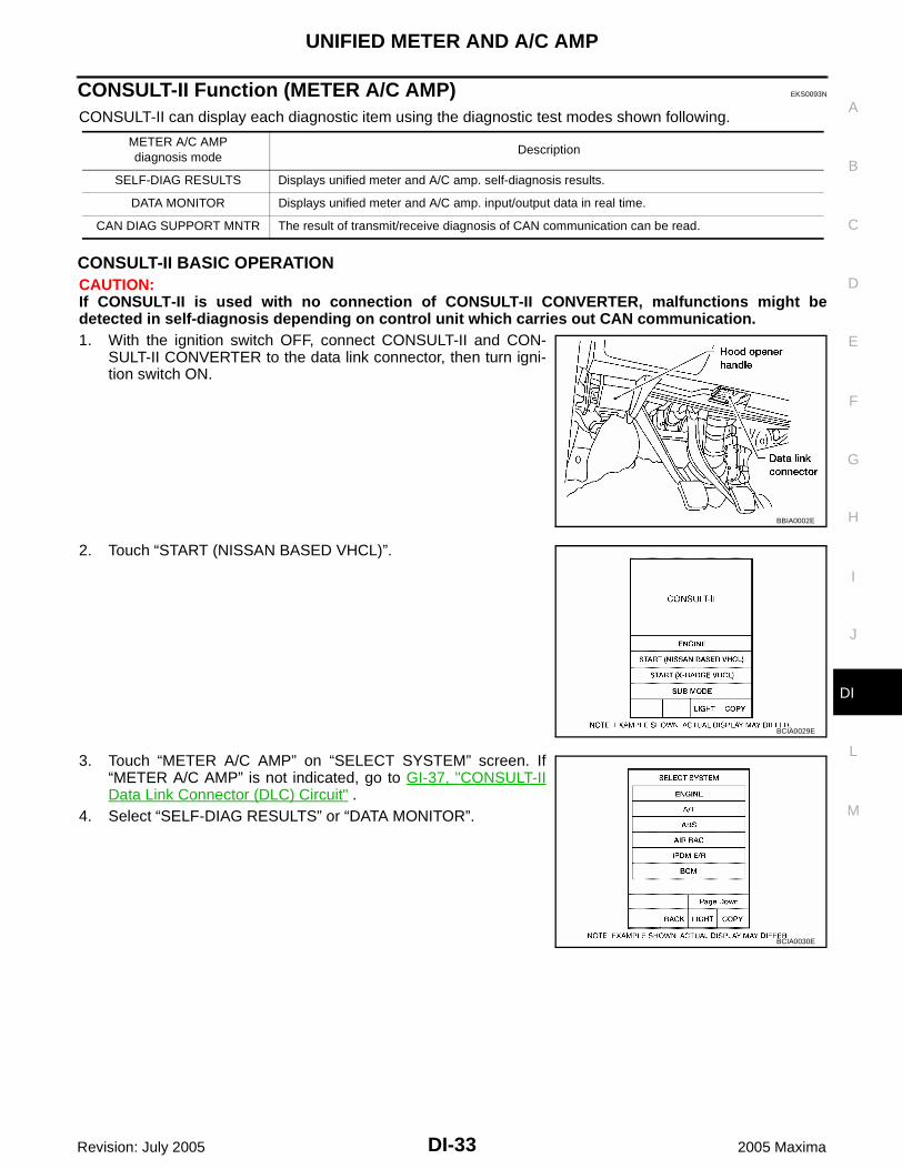
CONSULT-II Function (METER A/C AMP) EKS0093N
CONSULT-II can display each diagnostic item using the diagnostic test modes shown following.
CONSULT-II BASIC OPERATIONCAUTION:If CONSULT-II is used with no connection of CONSULT-II CONVERTER, malfunctions might bedetected in self-diagnosis depending on control unit which carries out CAN communication.1. With the ignition switch OFF, connect CONSULT-II and CON-
SULT-II CONVERTER to the data link connector, then turn igni-tion switch ON.
2. Touch “START (NISSAN BASED VHCL)”.
3. Touch “METER A/C AMP” on “SELECT SYSTEM” screen. If“METER A/C AMP” is not indicated, go to GI-37, "CONSULT-IIData Link Connector (DLC) Circuit" .
4. Select “SELF-DIAG RESULTS” or “DATA MONITOR”.
METER A/C AMPdiagnosis mode
Description
SELF-DIAG RESULTS Displays unified meter and A/C amp. self-diagnosis results.
DATA MONITOR Displays unified meter and A/C amp. input/output data in real time.
CAN DIAG SUPPORT MNTR The result of transmit/receive diagnosis of CAN communication can be read.
BBIA0002E
BCIA0029E
BCIA0030E

DI-34
UNIFIED METER AND A/C AMP
Revision: July 2005 2005 Maxima
SELF-DIAGNOSTIC RESULTSOperation Procedure1. Touch “SELF-DIAG RESULTS” on “SELECT DIAG MODE” screen.2. Self-diagnosis results are displayed.
Display Item List
Time indicates the condition of the self-diagnosis results judged by each signal input. Normal: If the system is presently operating properly, but had a malfunction in the past, the time will indi-
cate “1-63”. Malfunction: Soon after detecting malfunctions by self-diagnoses or current malfunction, “0” is indicated.After the system returns to normal operating condition, every time the ignition switch is cycled (turned to OFFfrom ON), a value of one is added to the counter (i.e. “1”→“2”→“3”···“63”). When the ignition switch is cycled64 times, the result of the self-diagnoses will be erased. If a malfunction is detected again, “0” will be indi-cated.
DATA MONITOROperation Procedure1. Touch “DATA MONITOR” on “SELECT DIAG MODE” screen.2. Touch either “MAIN SIGNALS” or “SELECTION FROM MENU” on the “DATA MONITOR” screen.
3. Touch “START”.4. When “SELECTION FROM MENU” is selected, touch individual
items to be monitored. When “MAIN SIGNALS” is selected,main items will be monitored.
5. Touch “RECORD” while monitoring, then the status of the moni-tored item can be recorded. To stop recording, touch “STOP”.
SKIA4956E
CONSULT-II display Malfunction
CAN COMM CIRC [U1000]
Malfunction is detected in CAN communication lines.
CAUTION:Even when there is no malfunction on CAN communication system, malfunction may be misinterpreted when battery has low voltage (when maintaining 7V-8V for about 2 sec-onds) or 10A fuse [No. 19, located in the fuse block (J/B)] is removed.
METER COMM CIRC [B2202]Malfunction is detected in communication lines between combination meter and unified meter and A/C amp.
VEHICLE SPEED CIRC [B2205]
Malfunction is detected when an erroneous speed signal is input.
CAUTION:Even when there is no malfunction on speed signal system, malfunctions may be misin-terpreted when battery has low voltage (when maintaining 7V-8V for about 2 seconds).
MAIN SIGNALS Monitors main signals.
SELECTION FROM MENU Selects and monitors individual signal.
SKIA4957E

UNIFIED METER AND A/C AMP
DI-35
C
D
E
F
G
H
I
J
L
M
A
B
DI
Revision: July 2005 2005 Maxima
Display Item List
Display item [Unit]MAIN
SIGNALSSELECTIONFROM MENU
Contents
SPEED METER [km/h] or [mph] X XThis is the angle correction value after the speed signal from the ABS actuator and electric unit (control unit) is con-verted into the vehicle speed.
SPEED OUTPUT [km/h] or [mph] X XThis is the angle correction value before the speed signal from the ABS actuator and electric unit (control unit) is con-verted into the vehicle speed.
TACHO METER [rpm] X XThis is the converted value for the engine speed signal from the ECM.
W TEMP METER [°C] or [°F] X XThis is the converted value for the water temp signal from the ECM.
FUEL METER [lit.] X XThis is the processed value for the signal (resistance value) from the fuel gauge.
DISTANCE [km] X X
This is the calculated value for the speed signal from the ABS actuator and electric unit (control unit), the signal (resistance signal) from the fuel gauge and fuel consump-tion from ECM.
FUEL W/L [ON/OFF] X X Indicates [ON/OFF] condition of low-fuel warning lamp.
MIL [ON/OFF] X Indicates [ON/OFF] condition of malfunction indicator lamp.
SEAT BELT W/L [ON/OFF] X Indicates [ON/OFF] condition of seat belt warning lamp.
BUZZER [ON/OFF] X X Indicates [ON/OFF] condition of buzzer.
DOOR W/L [ON/OFF] X Indicates [ON/OFF] condition of door warning lamp.
HI-BEAM IND [ON/OFF] X Indicates [ON/OFF] condition of high beam indicator.
TURN IND [ON/OFF] X Indicates [ON/OFF] condition of turn indicator.
OIL W/L [ON/OFF] X Indicates [ON/OFF] condition of oil pressure warning lamp.
TCS IND [ON/OFF] X Indicates [ON/OFF] condition of TCS OFF indicator lamp.
VDC IND [ON/OFF] X Indicates [ON/OFF] condition of VDC OFF indicator lamp.
ABS W/L [ON/OFF] X Indicates [ON/OFF] condition of ABS warning lamp.
SLIP IND [ON/OFF] X Indicates [ON/OFF] condition of SLIP indicator lamp.
BRAKE W/L [ON/OFF] X Indicates [ON/OFF] condition of brake warning lamp. *1
M RANGE SW [ON/OFF] X X Indicates [ON/OFF] condition of manual mode range switch.
NM RANGE SW [ON/OFF] X XIndicates [ON/OFF] condition of except for manual mode range switch.
AT SFT UP SW [ON/OFF] X X Indicates [ON/OFF] condition of A/T shift-up switch.
AT SFT DWN SW [ON/OFF] X X Indicates [ON/OFF] condition of A/T shift-down switch.
BRAKE SW [ON/OFF] X Indicates [ON/OFF] condition of parking brake switch.
AT-M IND [ON/OFF] X X Indicates [ON/OFF] condition of A/T manual mode indicator.
AT-M GEAR [5-1/1] X XIndicates [5-1/1] condition of A/T manual mode gear posi-tion.
P RANGE IND [ON/OFF] X X Indicates [ON/OFF] condition of A/T shift P range indicator.
R RANGE IND [ON/OFF] X X Indicates [ON/OFF] condition of A/T shift R range indicator.
N RANGE IND [ON/OFF] X X Indicates [ON/OFF] condition of A/T shift N range indicator.
D RANGE IND [ON/OFF] X X Indicates [ON/OFF] condition of A/T shift D range indicator.
3 RANGE IND [ON/OFF] X X Indicates [ON/OFF] condition of A/T shift 3 range indicator.
2 RANGE IND [ON/OFF] X X Indicates [ON/OFF] condition of A/T shift 2 range indicator.
1 RANGE IND [ON/OFF] X X Indicates [ON/OFF] condition of A/T shift 1range indicator.
A/T IND [ON/OFF] X Indicates [ON/OFF] condition of A/T indicator.
DI-36
UNIFIED METER AND A/C AMP
Revision: July 2005 2005 Maxima
NOTE:Any monitored item that does not match the vehicle being diagnosed is deleted from the display automatically.*1: Monitor keeps indicating “OFF” when brake warning lamp is on because of parking brake operation or lowbrake fluid level. *2: CAN status indicates the condition of the CAN communication judged by each signal input. Normal: If no problems were found in the past, CAN status indicates “0”. If the system is presently operat-
ing properly, but had a malfunction in the past, the CAN status will indicate “39-1”. Malfunction: If there is a malfunction, CAN indicates “40”.After the system returns to its normal operating condition, every time the ignition switch is cycled (turned OFFfrom ON), a value will be removed from the counter (i.e. “39”→“38”→“37”···“1”). If a malfunction is detectedagain, CAN status indicates “40”. (Although the system has returned to normal operating condition, “0” is notimmediately indicated. To reset, select and press “ERASE” on the “SELF-DIAGNOSIS” screen.)
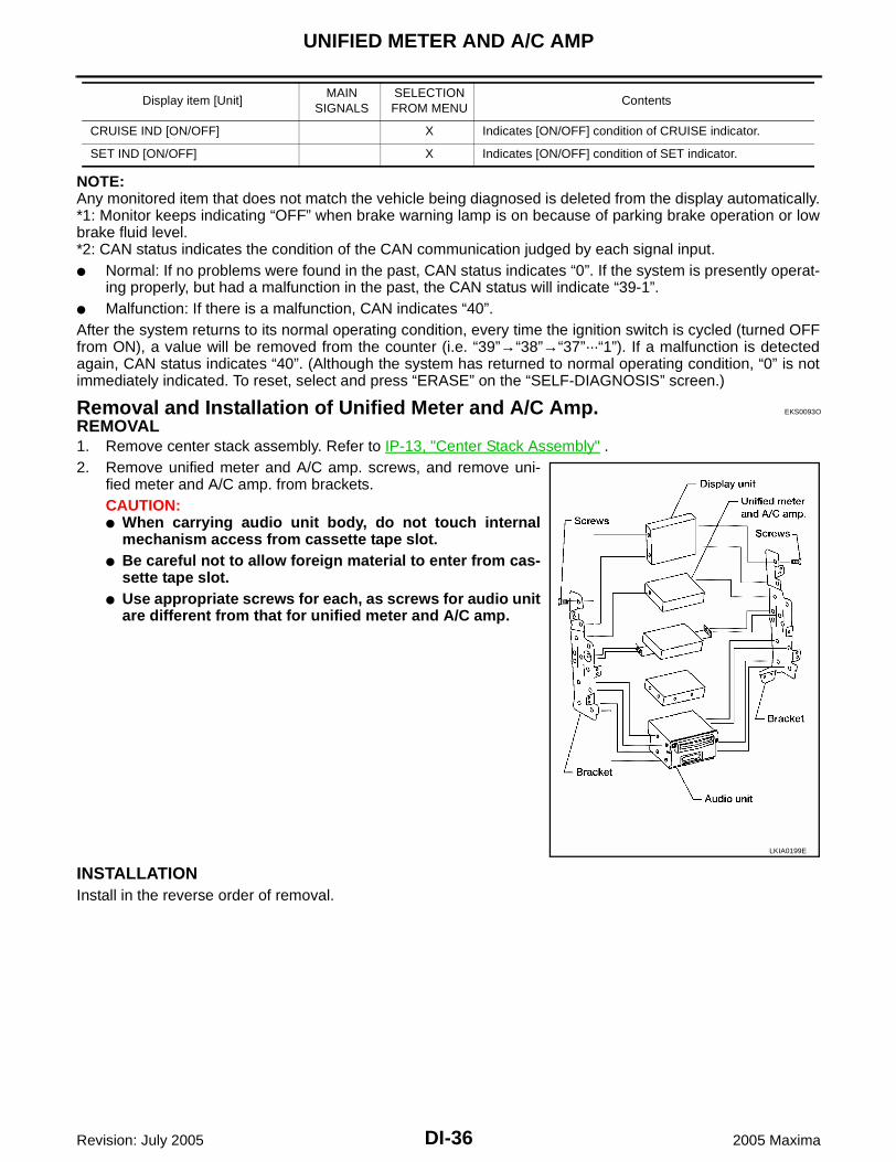
Removal and Installation of Unified Meter and A/C Amp. EKS0093O
REMOVAL1. Remove center stack assembly. Refer to IP-13, "Center Stack Assembly" .2. Remove unified meter and A/C amp. screws, and remove uni-
fied meter and A/C amp. from brackets.CAUTION: When carrying audio unit body, do not touch internal
mechanism access from cassette tape slot. Be careful not to allow foreign material to enter from cas-
sette tape slot. Use appropriate screws for each, as screws for audio unit
are different from that for unified meter and A/C amp.
INSTALLATIONInstall in the reverse order of removal.
CRUISE IND [ON/OFF] X Indicates [ON/OFF] condition of CRUISE indicator.
SET IND [ON/OFF] X Indicates [ON/OFF] condition of SET indicator.
Display item [Unit]MAIN
SIGNALSSELECTIONFROM MENU
Contents
LKIA0199E
COMPASS
DI-37
C
D
E
F
G
H
I
J
L
M
A
B
DI
Revision: July 2005 2005 Maxima
COMPASS PFP:24835
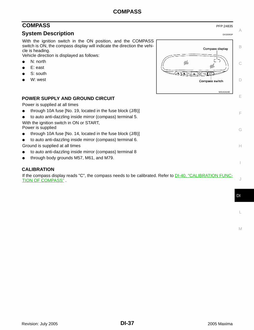
System Description EKS0093P
With the ignition switch in the ON position, and the COMPASSswitch is ON, the compass display will indicate the direction the vehi-cle is heading.Vehicle direction is displayed as follows: N: north E: east S: south W: west
POWER SUPPLY AND GROUND CIRCUITPower is supplied at all times through 10A fuse [No. 19, located in the fuse block (J/B)] to auto anti-dazzling inside mirror (compass) terminal 5.With the ignition switch in ON or START,Power is supplied through 10A fuse [No. 14, located in the fuse block (J/B)] to auto anti-dazzling inside mirror (compass) terminal 6.Ground is supplied at all times to auto anti-dazzling inside mirror (compass) terminal 8 through body grounds M57, M61, and M79.
CALIBRATIONIf the compass display reads "C", the compass needs to be calibrated. Refer to DI-40, "CALIBRATION FUNC-TION OF COMPASS" .
WKIA0424E

DI-38
COMPASS
Revision: July 2005 2005 Maxima
Wiring Diagram — COMPAS — EKS0093Q
WKWA0945E

COMPASS
DI-39
C
D
E
F
G
H
I
J
L
M
A
B
DI
Revision: July 2005 2005 Maxima
Trouble Diagnoses EKS0093R
COMPASS INSPECTIONSymptom Possible causes Repair order
No display at all 1. 10A fuse
2. Ground circuit
3. Compass
1. Check 10A fuse [No. 14, located in fuse block (J/B)].Turn the ignition switch ON and verify that battery positive volt-age is at terminal 6 of compass.
2. Check ground circuit for compass.
3. Replace compass.
Forward direction indi-cation slips off the mark or incorrect.
1. Compass not calibrated
2. Zone variation change is not done.
1. Drive the vehicle in 3 complete circles at less than 8 km/h (5 mph).
2. Perform the zone variation change procedure.
Compass reading remains unchanged.
Compass Replace compass.

DI-40
COMPASS
Revision: July 2005 2005 Maxima
Zone Variation Change Procedure EKS0093S
The difference between magnetic North and geographical North can sometimes be great enough to causefalse compass readings. This difference is known as variance. In order for the compass to operate properly(accurately) in a particular zone, the zone variation must be calibrated using the following procedure.
CALIBRATION FUNCTION OF COMPASSThe direction display is equipped with a calibration feature. If vehicledirection is not shown correctly, carry out initial correction.1. Pushing the COMPASS switch for about 10 seconds will enter
the initial calibration mode.2. Drive the vehicle slowly in a circle, in an open, safe place. The
initial calibration is completed in about three turns.NOTE:In places where the terrestrial magnetism is extremely disturbed, theinitial correction may start automatically.
WKIA0425E
WKIA0424E

WARNING LAMPS
DI-41
C
D
E
F
G
H
I
J
L
M
A
B
DI
Revision: July 2005 2005 Maxima
WARNING LAMPS PFP:24814
Schematic EKS0093T
WKWA1648E
DI-42
WARNING LAMPS
Revision: July 2005 2005 Maxima
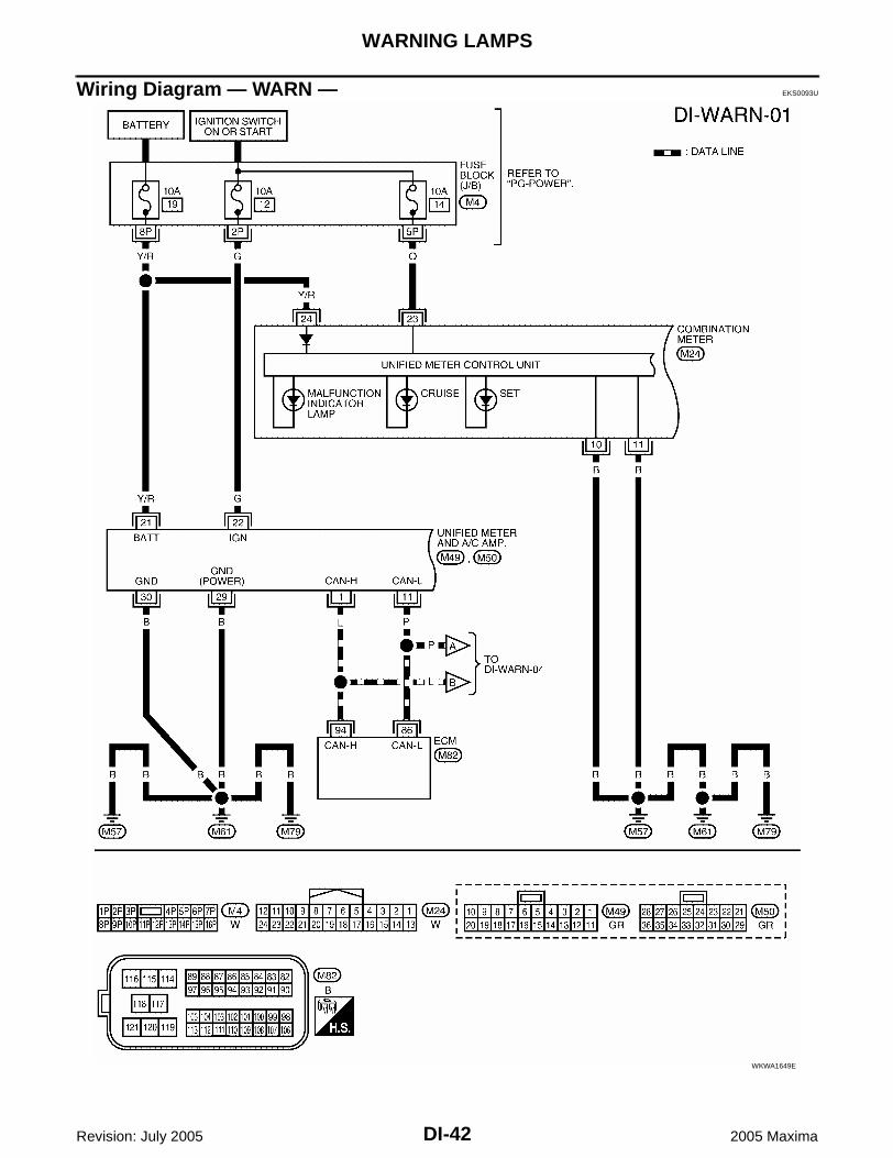
Wiring Diagram — WARN — EKS0093U
WKWA1649E

WARNING LAMPS
DI-43
C
D
E
F
G
H
I
J
L
M
A
B
DI
Revision: July 2005 2005 Maxima
WKWA1650E

DI-44
WARNING LAMPS
Revision: July 2005 2005 Maxima
WKWA1765E
WARNING LAMPS
DI-45
C
D
E
F
G
H
I
J
L
M
A
B
DI
Revision: July 2005 2005 Maxima
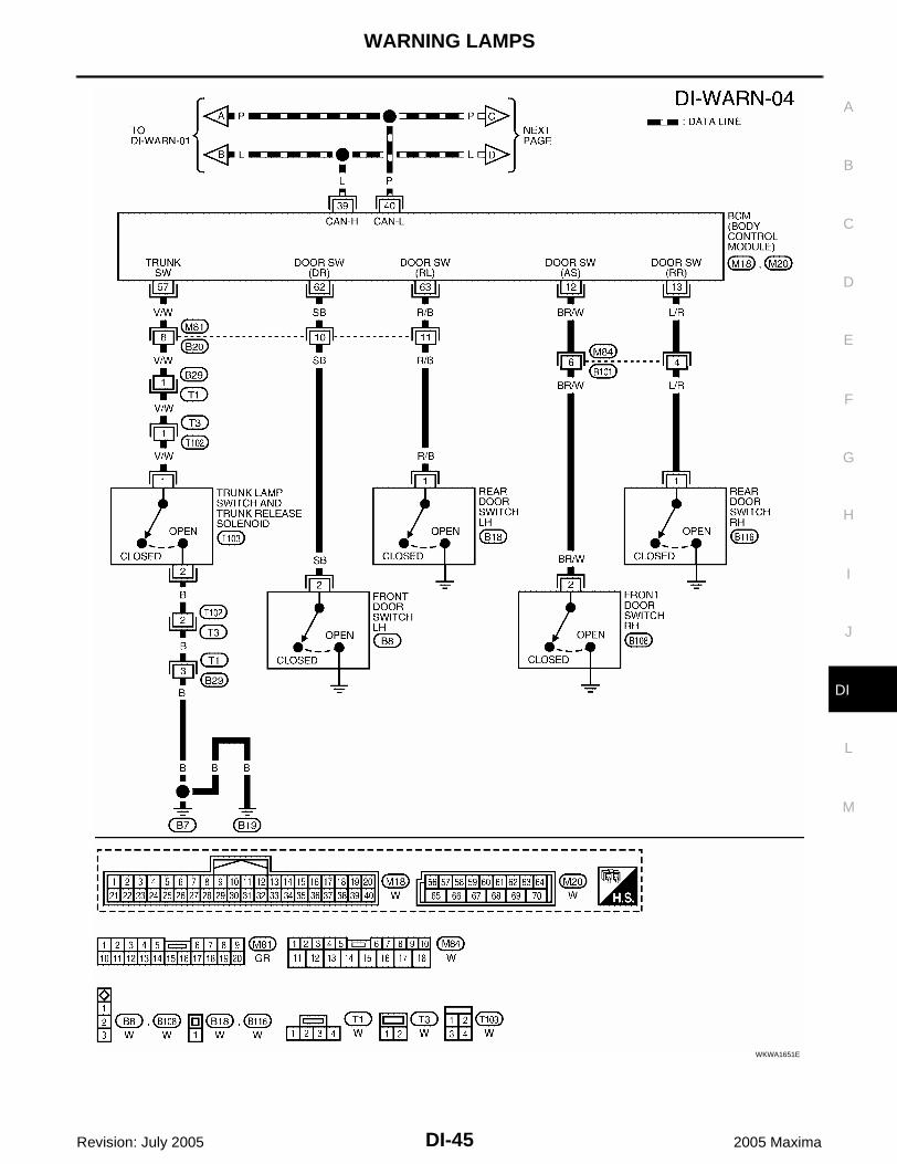
WKWA1651E

DI-46
WARNING LAMPS
Revision: July 2005 2005 Maxima
WKWA1652E

WARNING LAMPS
DI-47
C
D
E
F
G
H
I
J
L
M
A
B
DI
Revision: July 2005 2005 Maxima
Oil Pressure Warning Lamp Stays Off (Ignition Switch ON) EKS0093V
1. CHECK SELF-DIAGNOSTIC RESULTS OF UNIFIED METER AND A/C AMP.
1. Start engine.2. Select “METER A/C AMP” on CONSULT-II, and perform self-diagnosis of unified meter and A/C amp.
Refer to DI-33, "CONSULT-II Function (METER A/C AMP)" .3. After erasing the self-diagnostic results, perform self-diagnosis again.Self-diagnostic results contentNo malfunction detected>> GO TO 2.Malfunction detected>> Go to DI-19, "Symptom Chart 2" .
2. CHECK IPDM E/R OUTPUT SIGNAL
Activate IPDM E/R auto active test. Refer to PG-21, "Auto Active Test" .Is oil pressure warning lamp blinking?YES >> GO TO 5.NO >> GO TO 3.
3. CHECK BCM INPUT SIGNAL
Select “DATA MONITOR” of “SIGNAL BUFFER”. Refer to DI-34,"DATA MONITOR" . Operate ignition switch with “OIL P SW” of datamonitor and check operation status.
OK or NGOK >> GO TO 4.NG >> Replace the IPDM E/R. Refer to PG-27, "Removal and
Installation of IPDM E/R" .
4. CHECK UNIFIED METER AND A/C AMP. INPUT SIGNAL
Select “METER A/C AMP” on CONSULT-II. Operate ignition switchwith “OIL W/L” of data monitor and check operation status.
OK or NGOK >> Replace the combination meter. Refer to DI-29,
"Removal and Installation of Combination Meter" .NG >> Replace the BCM. Refer to BCS-20, "Removal and
Installation of BCM" .
When ignition switch is in ON position (Engine stopped)
: OIL P SW CLOSE
When engine running : OIL P SW OPEN
LKIA0403E
When ignition switch is in ON position (Engine stopped)
: OIL W/L ON
When engine running : OIL W/L OFF
LKIA0334E

DI-48
WARNING LAMPS
Revision: July 2005 2005 Maxima
5. CHECK OIL PRESSURE SWITCH CIRCUIT
1. Turn ignition switch OFF.2. Disconnect IPDM E/R connector E121 and oil pressure switch connector F106.3. Check continuity between IPDM E/R harness connector E121
terminal 57 (P/L) and oil pressure switch harness connectorF106 terminal + (R/L).
OK or NGOK >> GO TO 6.NG >> Repair harness or connector.
6. CHECK OIL PRESSURE SWITCH
Check oil pressure switch. Refer to DI-49, "OIL PRESSURE SWITCH" .OK or NGOK >> Replace the IPDM E/R. Refer to PG-27, "Removal and Installation of IPDM E/R" .NG >> Replace the oil pressure switch.
Oil Pressure Warning Lamp Does Not Turn Off (Oil Pressure Is Normal) EKS0093W
NOTE:For oil pressure inspection, refer to LU-7, "OIL PRESSURE CHECK" .
1. CHECK IPDM E/R OUTPUT SIGNAL
1. Disconnect oil pressure switch connector.2. Turn ignition switch ON.3. Check voltage between oil pressure switch harness connector
F106 terminal + (R/L) and ground.
OK or NGOK >> GO TO 2.NG >> GO TO 3.
2. CHECK OIL PRESSURE SWITCH
1. Turn ignition switch OFF.2. Check oil pressure switch. Refer to DI-49, "OIL PRESSURE SWITCH" .OK or NGOK >> Replace the IPDM E/R, refer to PG-27, "Removal and Installation of IPDM E/R" .NG >> Replace the oil pressure switch.
Continuity should exist.
LKIA0245E
Battery voltage should exist.
LKIA0246E

WARNING LAMPS
DI-49
C
D
E
F
G
H
I
J
L
M
A
B
DI
Revision: July 2005 2005 Maxima
3. CHECK OIL PRESSURE SWITCH CIRCUIT
1. Turn ignition switch OFF.2. Disconnect IPDM E/R connector E121.3. Check continuity between IPDM E/R harness connector E121
terminal 57 (P/L) and ground.
OK or NGOK >> Replace the IPDM E/R, refer to PG-27, "Removal and
Installation of IPDM E/R" .NG >> Repair harness or connector.
Component Inspection EKS0093X
OIL PRESSURE SWITCHCheck continuity between oil pressure switch and ground.
Continuity should not exist.
LKIA0247E
Condition Oil pressure kPa (kg/cm2 , psi) Continuity
Engine stopped Less than 29 (0.3. 4) Yes
Engine running More than 29 (0.3, 4) No
ELF0044D
DI-50
A/T INDICATOR
Revision: July 2005 2005 Maxima
A/T INDICATOR PFP:24814
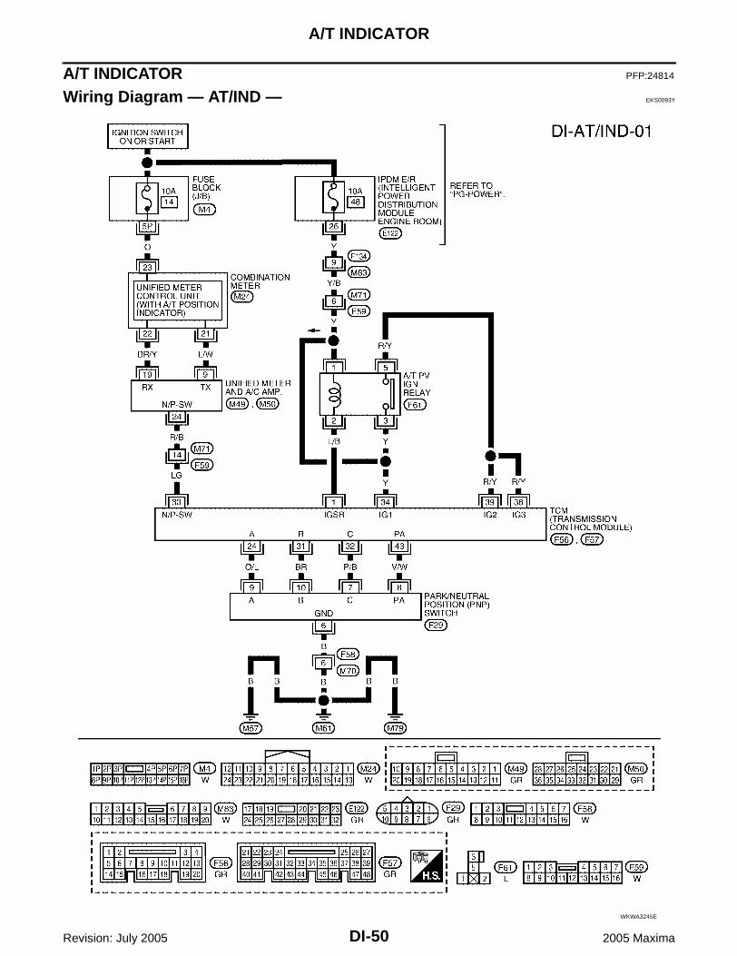
Wiring Diagram — AT/IND — EKS0093Y
WKWA3245E

A/T INDICATOR
DI-51
C
D
E
F
G
H
I
J
L
M
A
B
DI
Revision: July 2005 2005 Maxima
Trouble Diagnosis EKS0093Z
A/T Indicator Does Not Illuminate EKS00940
1. CHECK SELF-DIAGNOSIS OF COMBINATION METER
Perform combination meter self-diagnosis. Refer to DI-15, "HOW TOALTERNATE DIAGNOSIS MODE" .OK or NGOK >> GO TO 2.NG >> Replace combination meter. Refer to DI-29, "Removal
and Installation of Combination Meter" .
2. CHECK SELF-DIAGNOSIS RESULTS OF UNIFIED METER AND A/C AMP.
1. Start engine.2. Select "METER A/C AMP" on CONSULT-II, and perform self-diagnosis of unified meter and A/C amp.
Refer to DI-33, "CONSULT-II Function (METER A/C AMP)" .3. After erasing the self-diagnosis result, perform self-diagnosis again.Self-diagnosis results contentNo malfunction detected>>GO TO 3.Malfunction detected>>Go to DI-19, "Symptom Chart 2" .
LKIA0248E

DI-52
A/T INDICATOR
Revision: July 2005 2005 Maxima
3. CHECK UNIFIED METER AND A/C AMP. INPUT SIGNAL
1. Lift drive wheels.2. Connect CONSULT-II and start engine.3. Select "DATA MONITOR" of "METER A/C AMP". Confirm each
indication on the monitor when operating the shift lever.
OK or NGOK >> Replace combination meter. Refer to DI-29, "Removal and Installation of Combination Meter" .NG >> GO TO 4.
4. CHECK TCM
Perform self-diagnosis of TCM. Refer to AT-74, "CONSULT-II Function (TCM)" .OK or NGOK >> Replace the unified meter and A/C amp. Refer to DI-36, "Removal and Installation of Unified
Meter and A/C Amp." .NG >> Check the applicable parts.
CONSULT-II display Switch operationOperation
status
AT-M GEARManual mode range (shift up or down) 5-1
Except for manual mode range 1
P RANGE INDP range position ON
Except for P range position OFF
R RANGE INDR range position ON
Except for R range position OFF
N RANGE INDN range position ON
Except for N range position OFF
D RANGE INDD range position ON
Except for D range position OFF
3 RANGE IND3 range position ON
Except for 3 range position OFF
2 RANGE IND2 range position ON
Except for 2 range position OFF
1 RANGE IND1 range position ON
Except for 1 range position OFF
LKIA0249E

WARNING CHIME
DI-53
C
D
E
F
G
H
I
J
L
M
A
B
DI
Revision: July 2005 2005 Maxima
WARNING CHIME PFP:24814
Component Parts and Harness Connector Location EKS00941
System Description EKS00942
FUNCTIONPower is supplied at all times through 50A fusible link (letter f , located in the fuse and fusible link box) to BCM terminal 55, and through 10A fuse [No. 21, located in the fuse block (J/B)] to key switch and key lock solenoid terminal 3.With ignition switch ON or in START position, power is supplied through 10A fuse [No. 1, located in the fuse block (J/B)] to BCM terminal 38.Ground is supplied to BCM terminal 52, and to combination switch terminal 12 through body grounds M57, M61, and M79.NOTE:When ignition key warning chime, light warning chime, and seat belt warning chime should be conducted atthe same time, the priorities for each chime are the following.1. Light warning chime2. Ignition key warning chime3. Seat belt warning chime
IGNITION KEY WARNING CHIMEWith the key inserted in the ignition switch, the ignition switch in OFF position, and the driver's door open, thewarning chime will sound.Power is supplied
WKIA2972E

DI-54
WARNING CHIME
Revision: July 2005 2005 Maxima
through key switch and key lock solenoid terminal 4 to BCM terminal 37.Ground is supplied to BCM terminal 62 through front door switch LH terminal 2. Front door switch LH is case grounded.BCM sends door open signal to unified meter and A/C amp. via CAN communication lines.BCM detects key inserted into the ignition switch, and sends key warning signal to unified meter and A/C amp.via CAN communication lines. Unified meter and A/C amp. sends key warning signal to combination meter viacommunication line between unified meter and A/C amp. and combination meter.When combination meter receives key warning signal, it sounds warning chime.
LIGHT WARNING CHIMEWith the key removed from the ignition switch, the driver's door open, and the lighting switch (part of the com-bination switch) in 1st or 2nd position, the warning chime will sound. [This is the operation of the light warningchime, except when headlamp battery saver control operates (for 5 minutes after ignition switch is turned toOFF or ACC position) and headlamps do not illuminate.]Signal is supplied from combination switch (lighting switch) terminals 1, 2, 3, 4, 5, 6, 7, 8, 9 and 10 to BCM terminals 2, 3, 4, 5, 6, 32, 33, 34, 35 and 36.
NOTE:BCM detected lighting switch in 1st or 2nd position, refer to BCS-3, "COMBINATION SWITCH READINGFUNCTION" .
Ground is supplied to BCM terminal 62 through front door switch LH terminal 2. Front door switch LH is case grounded.BCM sends door open signal to unified meter and A/C amp. via CAN communication lines.BCM detects headlamps are illuminated, and sends light warning signal to unified meter and A/C amp. viaCAN communication lines. Unified meter and A/C amp. sends light warning signal to combination meter viacommunication line between unified meter and A/C amp. and combination meter.When combination meter receives light warning signal, it sounds warning chime.
SEAT BELT WARNING CHIMEWhen the ignition switch is turned ON with the seat belt unfastened [seat belt buckle switch LH unfastened],warning chime will sound for approximately 6 seconds.Ground is supplied to combination meter terminal 1 through seat belt buckle switch LH terminal 1.Seat belt buckle switch LH terminal 2 is grounded through body grounds B7 and B19.Combination meter sends seat belt buckle switch LH unfastened signal to unified meter and A/C amp. viacommunication line between unified meter and A/C amp. and combination meter.BCM receives seat belt buckle switch LH unfastened signal from unified meter and A/C amp. via CAN commu-nication line, and sends seat belt warning signal to unified meter and A/C amp. via CAN communication line.Unified meter and A/C amp. sends seat belt warning signal to combination meter via communication linebetween unified meter and A/C amp. and combination meter.When the combination meter receives the seat belt warning signal, it sounds the warning chime. The BCMcontrols the (6 second) duration of the seat belt warning chime.
CAN Communication System Description EKS00943
Refer to LAN-7, "CAN COMMUNICATION" .

WARNING CHIME
DI-55
C
D
E
F
G
H
I
J
L
M
A
B
DI
Revision: July 2005 2005 Maxima
Wiring Diagram — CHIME — EKS00944
WKWA1766E

DI-56
WARNING CHIME
Revision: July 2005 2005 Maxima
WKWA1653E
WARNING CHIME
DI-57
C
D
E
F
G
H
I
J
L
M
A
B
DI
Revision: July 2005 2005 Maxima
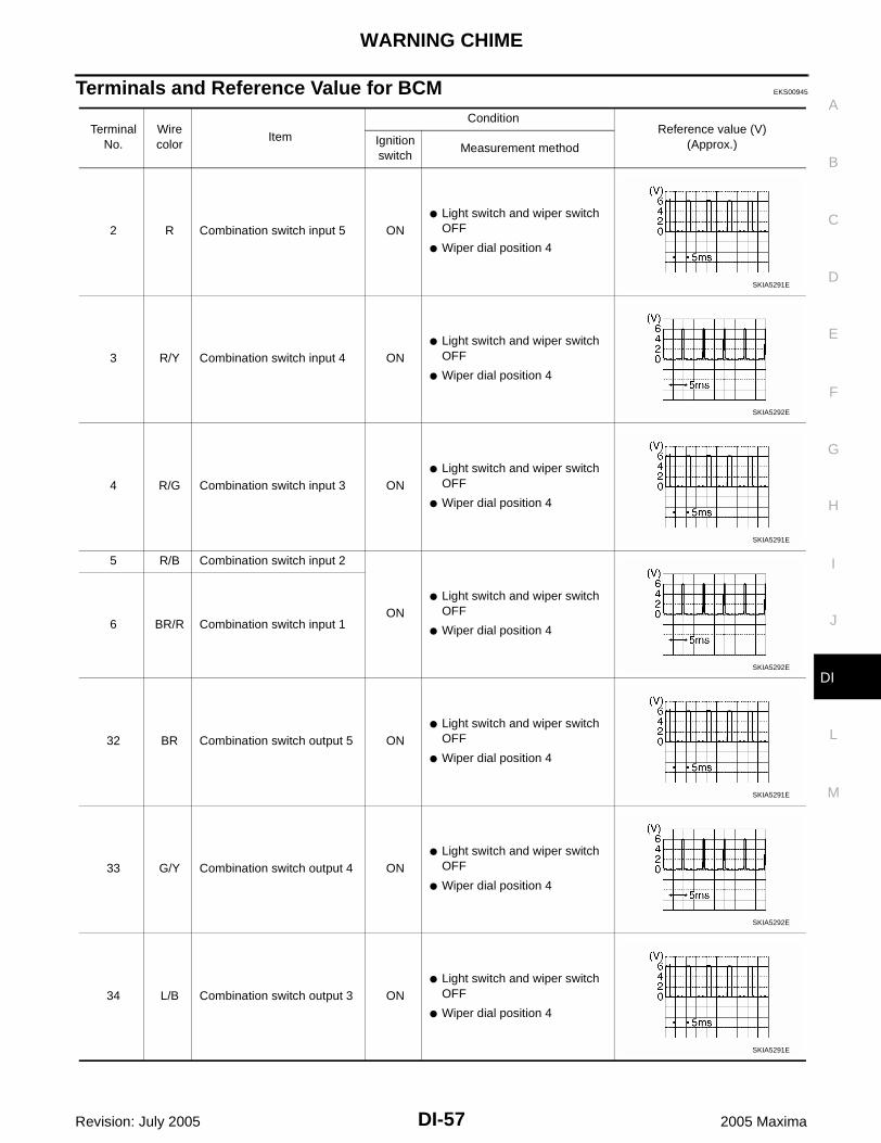
Terminals and Reference Value for BCM EKS00945
Terminal No.
Wire color
Item
ConditionReference value (V)
(Approx.)Ignition switch
Measurement method
2 R Combination switch input 5 ON Light switch and wiper switch
OFF
Wiper dial position 4
3 R/Y Combination switch input 4 ON Light switch and wiper switch
OFF
Wiper dial position 4
4 R/G Combination switch input 3 ON Light switch and wiper switch
OFF
Wiper dial position 4
5 R/B Combination switch input 2
ON Light switch and wiper switch
OFF
Wiper dial position 46 BR/R Combination switch input 1
32 BR Combination switch output 5 ON Light switch and wiper switch
OFF
Wiper dial position 4
33 G/Y Combination switch output 4 ON Light switch and wiper switch
OFF
Wiper dial position 4
34 L/B Combination switch output 3 ON Light switch and wiper switch
OFF
Wiper dial position 4
SKIA5291E
SKIA5292E
SKIA5291E
SKIA5292E
SKIA5291E
SKIA5292E
SKIA5291E
DI-58
WARNING CHIME
Revision: July 2005 2005 Maxima
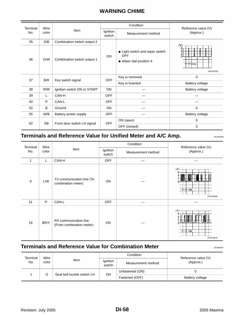
Terminals and Reference Value for Unified Meter and A/C Amp. EKS00946
Terminals and Reference Value for Combination Meter EKS00947
35 G/B Combination switch output 2
ON Light switch and wiper switch
OFF
Wiper dial position 436 G/W Combination switch output 1
37 B/R Key switch signal OFFKey is removed 0
Key is inserted Battery voltage
38 R/W Ignition switch ON or START ON — Battery voltage
39 L CAN-H OFF — —
40 P CAN-L OFF — —
52 B Ground ON — 0
55 W/B Battery power supply OFF — Battery voltage
62 SB Front door switch LH signal OFFON (open) 0
OFF (closed) 5
Terminal No.
Wire color
Item
ConditionReference value (V)
(Approx.)Ignition switch
Measurement method
SKIA5292E
Terminal No.
Wire color
Item
ConditionReference value (V)
(Approx.)Ignition switch
Measurement method
1 L CAN-H OFF — —
9 L/WTX communication line (To combination meter)
ON —
11 P CAN-L OFF — —
19 BR/YRX communication line (From combination meter)
ON —
SKIA3362E
SKIA3361E
Terminal No.
Wire color
Item
ConditionReference value (V)
(Approx.)Ignition switch
Measurement method
1 O Seat belt buckle switch LH ONUnfastened (ON) 0
Fastened (OFF) Battery voltage

WARNING CHIME
DI-59
C
D
E
F
G
H
I
J
L
M
A
B
DI
Revision: July 2005 2005 Maxima
How to Proceed With Trouble Diagnosis EKS00948
1. Confirm the symptom or customer complaint.2. Understand operation description and function description. Refer to DI-53, "System Description" .3. Perform the preliminary check. Refer to DI-59, "Preliminary Check" .4. Start engine.5. Select “METER A/C AMP” on CONSULT-II, and perform self-diagnosis of unified meter and A/C amp.
Refer to DI-33, "CONSULT-II Function (METER A/C AMP)" . When no malfunction is detected, go to step7. When malfunction is detected, go to DI-34, "Display Item List" .
6. After erasing the self-diagnostic results, perform self-diagnosis again. When no malfunction is detected,go to DI-19, "Symptom Chart 2" .
7. Check symptom and repair or replace the cause of malfunction.8. Does the warning chime operate properly? If so, go to 9. If not, go to 5.9. Inspection End.
Preliminary Check EKS00949
INSPECTION FOR POWER SUPPLY AND GROUND CIRCUIT
1. CHECK FUSE
Check for blown BCM fuses.
Refer to DI-55, "Wiring Diagram — CHIME —" .
OK or NGOK >> GO TO 2.NG >> If fuse is blown, be sure to eliminate cause of malfunction before installing new fuse. Refer to PG-
4, "POWER SUPPLY ROUTING CIRCUIT" .
21 L/WTX communication line (From unified meter and A/C amp.)
ON —
22 BR/YRX communication line (To unified meter and A/C amp.)
ON —
Terminal No.
Wire color
Item
ConditionReference value (V)
(Approx.)Ignition switch
Measurement method
SKIA3362E
SKIA3361E
Unit Power source Fuse No.
BCMBattery f
Ignition switch ON or START 1

DI-60
WARNING CHIME
Revision: July 2005 2005 Maxima
2. CHECK POWER SUPPLY CIRCUIT
1. Disconnect BCM connector M18 and M19.2. Check voltage between BCM harness connector terminals and
ground.
OK or NGOK >> GO TO 3.NG >> Check harness for open between BCM and fuse.
3. CHECK GROUND CIRCUIT
1. Turn ignition switch OFF. 2. Check continuity between BCM harness connector M19 terminal
52 (B), and ground.
OK or NGOK >> Inspection End.NG >> Repair harness or connector.
Terminals Ignition switch position
(+)
(–) OFF ACC ONConnector
Terminal (Wire color)
M19 55 (W/B)
Ground
Battery voltage
Battery voltage
Battery voltage
M18 38 (R/W) 0V 0VBattery voltage LKIA0251E
Continuity should exist.
WKIA2973E

WARNING CHIME
DI-61
C
D
E
F
G
H
I
J
L
M
A
B
DI
Revision: July 2005 2005 Maxima
CONSULT-II Function (BCM) EKS0094A
CONSULT-II can display each diagnostic item using the diagnostic test modes shown following.
CONSULT-II BASIC OPERATION PROCEDURECAUTION:If CONSULT-II is used with no connection of CONSULT-II CONVERTER, malfunctions might bedetected in self-diagnosis depending on control unit which carries out CAN communication.1. With the ignition switch OFF, connect CONSULT-II and CON-
SULT-II CONVERTER to the data link connector, and turn igni-tion switch ON.
2. Touch “START (NISSAN BASED VHCL)”.
3. Touch “BCM” on “SELECT SYSTEM” screen. If “BCM” is notindicated, go to GI-37, "CONSULT-II Data Link Connector (DLC)Circuit" .
BCM diagnostic test item
Diagnostic mode Description
Inspection by part
WORK SUPPORTSupports inspections and adjustments. Commands are transmitted to the BCM for setting the status suitable for required operation, input/output signals are received from the BCM and received data is displayed.
DATA MONITOR Displays BCM input/output data in real time.
ACTIVE TEST Operation of electrical loads can be checked by sending drive signal to them.
SELF-DIAG RESULTS Displays BCM self-diagnosis results.
CAN DIAG SUPPORT MNTR The result of transmit/receive diagnosis of CAN communication can be read.
ECU PART NUMBER BCM part number can be read.
CONFIGURATION Performs BCM configuration read/write functions.
BBIA0002E
BCIA0029E
BCIA0030E

DI-62
WARNING CHIME
Revision: July 2005 2005 Maxima
4. Touch "BUZZER" or “BCM”.5. Select “DATA MONITOR”, “ACTIVE TEST” or “SELF-DIAG
RESULTS”.
DATA MONITOROperation Procedure1. Touch “BUZZER” on “SELECT TEST ITEM” screen.2. Touch “DATA MONITOR” on “SELECT DIAG MODE” screen.3. Touch “ALL SIGNALS” or “SELECTION FROM MENU” on “DATA MONITOR″ screen.
4. Touch “START”.5. If “SELECTION FROM MENU” is selected, touch the item you desire to monitor. If “ALL SIGNALS” is
selected, all control items are monitored.6. During monitoring, touching “RECORD” can start recording the monitored item status.
Data Monitor Item
ACTIVE TESTOperation Procedure1. Touch “BUZZER” on “SELECT TEST ITEM” screen.2. Touch “ACTIVE TEST” on “SELECT DIAG MODE” screen.3. Touch the item to be tested, and check the operation.4. During the operation check, touching “OFF” deactivates the operation.
Active Test Item
SELF-DIAGNOSTIC RESULTSOperation Procedure1. Touch “BCM” on “SELECT TEST ITEM” screen.2. Touch “SELF-DIAG RESULTS” on “SELECT DIAG MODE” screen.3. Self-diagnostic results are displayed.
SKIA5788E
ALL SIGNALS Monitors main items.
SELECTION FROM MENU Selects and monitors items.
Monitored item Description
IGN ON SW Indicates [ON/OFF] condition of ignition switch.
KEY ON SW Indicates [ON/OFF] condition of key switch.
DOOR SW-DR Indicates [ON/OFF] condition of front door switch (driver side).
TAIL LAMP SW Indicates [ON/OFF] condition of lighting switch.
Test item Malfunction is detected when
LIGHT WARN ALMThis test is able to check light warning chime operation. Light warning chime sounds for 2 sec-onds after touching “ON” on CONSULT-II screen.
IGN KEY WARN ALMThis test is able to check key warning chime operation. Key warning chime sounds for 2 seconds after touching “ON” on CONSULT-II screen.
SEAT BELT WARNThis test is able to check seat belt warning chime operation. Seat belt warning chime sounds for 2 seconds after touching “ON” on CONSULT-II screen.

WARNING CHIME
DI-63
C
D
E
F
G
H
I
J
L
M
A
B
DI
Revision: July 2005 2005 Maxima
Display Item List
NOTE:If "CAN communication [U1000]" is indicated, after printing the monitor item, go to "CAN System". Refer toLAN-7, "CAN COMMUNICATION" .
All Warning Chimes Do Not Operate EKS0094B
1. CHECK CHIME OPERATION
Select “BUZZER” on CONSULT-II, and perform “LIGHT WARNALM”, “IGN KEY WARN ALM”, OR “SEAT BELT WARN TEST”active test.Does chime sound?YES >> Replace the BCM. Refer to BCS-20, "Removal and
Installation of BCM" .NO >> GO TO 2.
2. CHECK UNIFIED METER AND A/C AMP. INPUT SIGNAL
Select “METER A/C AMP” on CONSULT-II. Observe “BUZZER” ofdata monitor while operating switches in order to meet the require-ments to sound warning chime.
OK or NGOK >> Replace the combination meter. Refer to DI-29,
"Removal and Installation of Combination Meter" .NG >> Replace the BCM. Refer to BCS-20, "Removal and
Installation of BCM" .
Monitored Item CONSULT-II display Description
CAN communication CAN communication [U1000] Malfunction is detected in CAN communication.
SKIA6331E
When requirements are met to sound warning chime
: BUZZER ON
Except above : BUZZER OFF
PKIA2063E

DI-64
WARNING CHIME
Revision: July 2005 2005 Maxima
Key Warning Chime and Light Warning Chime Do Not Operate (Seat Belt Warn-ing Chime Does Operate) EKS0094C
1. CHECK BCM INPUT SIGNAL
With CONSULT-II1. Select "BCM" on CONSULT-II. 2. With "DATA MONITOR" of "BUZZER", confirm "DOOR SW-DR"
changes with the status of front door LH.
Without CONSULT-II1. Turn ignition switch OFF.2. Disconnect BCM connector M20.3. Check continuity between BCM harness connector M20 terminal
62 (SB) and ground.
OK or NGOK >> Replace the BCM. Refer to BCS-20, "Removal and
Installation of BCM" .NG >> GO TO 2.
2. CHECK FRONT DOOR SWITCH LH CIRCUIT
1. Turn ignition switch OFF.2. Disconnect BCM connector and front door switch LH connector.3. Check continuity between BCM harness connector M20 terminal
62 (SB) and front door switch LH harness connector B8 terminal2 (SB).
4. Check continuity between BCM harness connector M20 terminal62 (SB) and ground.
OK or NGOK >> GO TO 3.NG >> Repair harness or connector.
When front door LH is opened
: DOOR SW-DR ON
When front door LH is closed
: DOOR SW-DR OFF
LKIA0335E
When front door LH is opened
: Continuity should exist.
When front door LH is closed
: Continuity should not exist.
LKIA0327E
Continuity should exist.
Continuity should not exist.
LKIA0253E

WARNING CHIME
DI-65
C
D
E
F
G
H
I
J
L
M
A
B
DI
Revision: July 2005 2005 Maxima
3. CHECK FRONT DOOR SWITCH LH AND GROUND CIRCUIT
Check continuity between front door switch LH terminal 2 andground while switching the door switch from ON (open) to OFF(closed).
OK or NGOK >> Replace the BCM. Refer to BCS-20, "Removal and
Installation of BCM" .NG >> Replace the front door switch LH.
Key Warning Chime Does Not Operate EKS0094D
1. CHECK FUSE
Check if the key switch fuse [fuse 21, located in the fuse block (J/B)] is blown. Refer to DI-55, "Wiring Diagram— CHIME —" .Is the fuse blown?YES >> Replace the fuse. Be sure to repair the cause of malfunction before installing new fuse.NO >> GO TO 2.
2. CHECK WARNING CHIME OPERATION
With key removed from the ignition and the front door LH open, turn the lighting switch to 1st or 2nd position.Does warning chime sound?YES >> GO TO 3.NO >> Go to DI-63, "All Warning Chimes Do Not Operate" or DI-64, "Key Warning Chime and Light
Warning Chime Do Not Operate (Seat Belt Warning Chime Does Operate)" .
When front door switch LH is pressed
: Continuity should not exist.
When front door switch LH is released
: Continuity should exist.
WKIA1517E
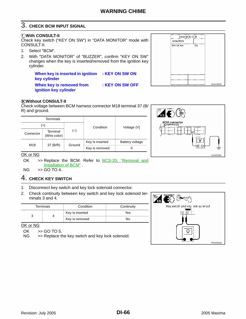
DI-66
WARNING CHIME
Revision: July 2005 2005 Maxima
3. CHECK BCM INPUT SIGNAL
With CONSULT-IICheck key switch (“KEY ON SW”) in “DATA MONITOR” mode withCONSULT-II.1. Select "BCM". 2. With "DATA MONITOR" of "BUZZER", confirm "KEY ON SW"
changes when the key is inserted/removed from the ignition keycylinder.
Without CONSULT-IICheck voltage between BCM harness connector M18 terminal 37 (B/R) and ground.
OK or NGOK >> Replace the BCM. Refer to BCS-20, "Removal and
Installation of BCM" .NG >> GO TO 4.
4. CHECK KEY SWITCH
1. Disconnect key switch and key lock solenoid connector.2. Check continuity between key switch and key lock solenoid ter-
minals 3 and 4.
OK or NGOK >> GO TO 5.NG >> Replace the key switch and key lock solenoid.
When key is inserted in ignition key cylinder
: KEY ON SW ON
When key is removed from ignition key cylinder
: KEY ON SW OFF SKIA1960E
Terminals
Condition Voltage (V)(+)
(–)Connector
Terminal (Wire color)
M18 37 (B/R) GroundKey is inserted Battery voltage
Key is removed 0
LKIA0255E
Terminals Condition Continuity
3 4Key is inserted Yes
Key is removed No
PKIA2503E
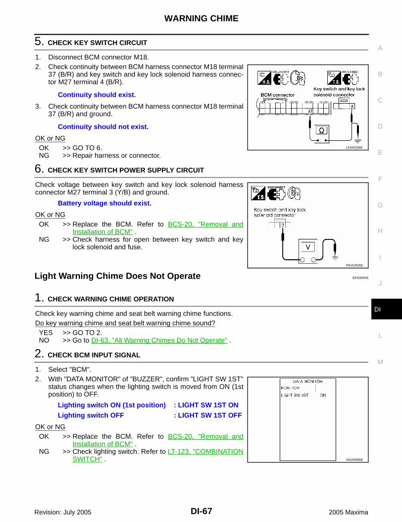
WARNING CHIME
DI-67
C
D
E
F
G
H
I
J
L
M
A
B
DI
Revision: July 2005 2005 Maxima
5. CHECK KEY SWITCH CIRCUIT
1. Disconnect BCM connector M18.2. Check continuity between BCM harness connector M18 terminal
37 (B/R) and key switch and key lock solenoid harness connec-tor M27 terminal 4 (B/R).
3. Check continuity between BCM harness connector M18 terminal37 (B/R) and ground.
OK or NGOK >> GO TO 6.NG >> Repair harness or connector.
6. CHECK KEY SWITCH POWER SUPPLY CIRCUIT
Check voltage between key switch and key lock solenoid harnessconnector M27 terminal 3 (Y/B) and ground.
OK or NGOK >> Replace the BCM. Refer to BCS-20, "Removal and
Installation of BCM" .NG >> Check harness for open between key switch and key
lock solenoid and fuse.
Light Warning Chime Does Not Operate EKS0094E
1. CHECK WARNING CHIME OPERATION
Check key warning chime and seat belt warning chime functions.Do key warning chime and seat belt warning chime sound?YES >> GO TO 2.NO >> Go to DI-63, "All Warning Chimes Do Not Operate" .
2. CHECK BCM INPUT SIGNAL
1. Select "BCM".2. With "DATA MONITOR" of "BUZZER", confirm "LIGHT SW 1ST"
status changes when the lighting switch is moved from ON (1stposition) to OFF.
OK or NGOK >> Replace the BCM. Refer to BCS-20, "Removal and
Installation of BCM" .NG >> Check lighting switch. Refer to LT-123, "COMBINATION
SWITCH" .
Continuity should exist.
Continuity should not exist.
LKIA0256E
Battery voltage should exist.
PKIA2505E
Lighting switch ON (1st position) : LIGHT SW 1ST ONLighting switch OFF : LIGHT SW 1ST OFF
SKIA5956E

DI-68
WARNING CHIME
Revision: July 2005 2005 Maxima
Seat Belt Warning Chime Does Not Operate EKS0094F
1. CHECK WARNING CHIME OPERATION
1. With key removed from the ignition and the front door LH open, turn the lighting switch to 1st or 2nd posi-tion.
2. Return lighting switch to OFF position, and insert key into ignition.Does warning chime sound for both steps?YES >> GO TO 2.NO >> Go to DI-63, "All Warning Chimes Do Not Operate" .
2. CHECK BCM INPUT SIGNAL
With “SEAT BELT ALM” on the data monitor, confirm “SEAT BELT SW” when the seat belt buckle switch LH isoperated.1. Select "METER A/C AMP".2. With "DATA MONITOR" of "METER A/C AMP", confirm "SEAT
BELT W/L" status changes with the operation of the seat belt.
OK or NGOK >> Replace the BCM. Refer to BCS-20, "Removal and Installation of BCM" .NG >> GO TO 3.
3. CHECK COMBINATION METER INPUT SIGNAL
1. Turn ignition switch ON.2. Check voltage between combination meter harness connector
M24 terminal 1 (O) and ground.
OK or NGOK >> Replace the combination meter. Refer to DI-29, "Removal and Installation of Combination Meter" .NG >> GO TO 4.
When seat belt LH is fastened : SEAT BELT W/L OFFWhen seat belt LH is unfastened : SEAT BELT W/L ON
LKIA0336E
Terminals
ConditionVoltage (V)(Approx.)
(+)(–)
Connector Terminal
M24 1 (O) GroundSeat belt is fastened Battery voltage
Seat belt is unfastened 0
LKIA0257E
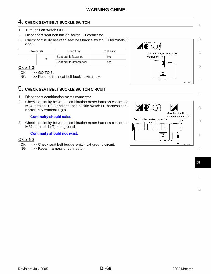
WARNING CHIME
DI-69
C
D
E
F
G
H
I
J
L
M
A
B
DI
Revision: July 2005 2005 Maxima
4. CHECK SEAT BELT BUCKLE SWITCH
1. Turn ignition switch OFF.2. Disconnect seat belt buckle switch LH connector.3. Check continuity between seat belt buckle switch LH terminals 1
and 2.
OK or NGOK >> GO TO 5.NG >> Replace the seat belt buckle switch LH.
5. CHECK SEAT BELT BUCKLE SWITCH CIRCUIT
1. Disconnect combination meter connector.2. Check continuity between combination meter harness connector
M24 terminal 1 (O) and seat belt buckle switch LH harness con-nector P15 terminal 1 (O).
3. Check continuity between combination meter harness connectorM24 terminal 1 (O) and ground.
OK or NGOK >> Check seat belt buckle switch LH ground circuit.NG >> Repair harness or connector.
Terminals Condition Continuity
1 2Seat belt is fastened No
Seat belt is unfastened Yes
LKIA0258E
Continuity should exist.
Continuity should not exist.
LKIA0259E

DI-70
WARNING CHIME
Revision: July 2005 2005 Maxima