dresser micro series volume corrector - - ge oil and gas | ge oil & gas the imc/w2 is set up and...
TRANSCRIPT

Dresser* Micro Series Volume Corrector - Model IMC/W2 Hardware Manual
GE Oil & Gas

2 | GE Oil & Gas
Table of Contents 1. Information ...........................................................................................................................................................22. General Overview ..............................................................................................................................................2 2.1 Models Available ...................................................................................................................................4 2.1.1 Canadian Configuration ...............................................................................................................4 2.1.2 USA Configuration ...........................................................................................................................4 Table 1 – IMC/W2 Model Options Reference Table ..............................................................5 2.1.3 Accessories ..........................................................................................................................................53. Specification and Details ...............................................................................................................................6 3.1 Pressure Measurement ....................................................................................................................6 Table 2 – Pressure Transducer Accuracy Reference Table .............................................6 3.2 Temperature Measurement ...........................................................................................................7 3.3 Volume Input ..........................................................................................................................................7 3.4 Pulse Output ...........................................................................................................................................7 3.5 Units of Measurement .......................................................................................................................8 3.6 Meter Dimensions ................................................................................................................................8 Figure 1 - IMC/W2 Dimensions .......................................................................................................8 Table 3 - IMC/W2 and Meter Dimension Table ......................................................................9 3.7 Serial Port ..............................................................................................................................................10 3.8 Display ....................................................................................................................................................10 Table 4 – LCD and Alarm Conditions ........................................................................................11 3.9 Memory ..................................................................................................................................................11 3.10 Internal Supply .................................................................................................................................12 3.11 Environment......................................................................................................................................124 Safety .....................................................................................................................................................................135 Installation ..........................................................................................................................................................13 5.1 Unpacking .............................................................................................................................................13 5.2 Safety Requirements .......................................................................................................................13 5.3 EMC Compatibility .............................................................................................................................14 5.4 Mechanical Installation ..................................................................................................................14 Figure 2 – IMC/W2 Meter Mounting Guide ............................................................................14 5.4.1 Setting the Weights and Measures Link ............................................................................15 Figure 3 – Setting the Weights and Measure Link .............................................................16 5.5 Electrical Installation .......................................................................................................................17 5.5.1 Location of the Connection Terminals ...............................................................................17 Figure 4 – Location of the Connection Terminals ..............................................................18 5.5.1.1 Volume Input (TB1) ....................................................................................................................19 Figure 5 – TBI Connections ............................................................................................................19 5.5.1.2 Temperature Measurement (TB2) .....................................................................................20 Figure 6 – Temperature Transducer Connections (TB2) .................................................20 5.5.1.3 Pulse Output (TB3) .....................................................................................................................21 Figure 7 – Pulse Output Connections (TB3) ...........................................................................216. Accuracy Test ...................................................................................................................................................217. Maintenance .....................................................................................................................................................21 7.1 Replacing the Battery Pack .........................................................................................................22 Figure 8 - Change Battery Type ..................................................................................................23 7.2 Pressure Transducer Recalibration .........................................................................................23 7.3 Temperature Recalibration ..........................................................................................................23 7.4 Restoring Factory Defaults ..........................................................................................................23 7.5 Service ....................................................................................................................................................23

IMCW2 Hardware Handbook | 3
1. InformationAll printed material contained within this handbook is for information only and is subject to change without notice.
This manual uses the words corrector, corrected and uncorrected throughout. The words corrector, corrected and uncorrected should be read in Europe as meaning convertor, converted and unconverted as defined by the most recent standards on volume conversion.
In the case of the IMC/W2 T-Only and when a fixed line pressure is applied, the corrected and uncorrected volumes should be read as meaning compensated and noncompensated.
2. General OverviewThe Dresser Integral Micro Series Volume Corrector Model IMC/W2 combines 2 devices; an electronic counter and a volume corrector. The IMC/W2 is installed directly onto all Dresser meters and meters from certain other manufacturers. Volume is sensed from the rotation of the impellers via a Wiegand sensor, therefore the input signal to the electronic counter and volume corrector is of high resolution. This translates into extremely high accuracy volume measurement and correction. The lack of a mechanical counter increases the rangeability of the gas meter and decreases the starting flow rate of the meter.
The IMC/W2 is designed to measure live pressure and temperature to calculate corrected volume.
NOTE: a temperature only version of the IMC/W2, the IMC/W2 T-Only is also available. The IMC/W2 T-Only measures live temperature and the operator is able to configure a fixed line pressure value. All functionality, with exception of the live pressure measurement is identical to that of the IMC/W2, and the details contained within this handbook should be read as being applicable to both.
The IMC/W2 utilizes E2PROM memory which eliminates the need for back up batteries and all set up data, data and audit log entries will be stored during periods of no power. The data logging facility provides the operator with 3 independent operator configurable logging periods. The audit logging facility provides a means of tracking up to the latest 32 changes to the configuration parameters. Both the data and audit logs are saved as CSV (comma-delimited) files to allow easy import into spreadsheets such as Microsoft® Excel. For further details regarding the data and audit logging facility consult the IMC/W2 User Terminal Manual.
The IMC/W2 unit is designed (and approved intrinsically safe (I.S.) for use in hazardous areas. A serial port allows communication with the unit.

4 | GE Oil & Gas
The IMC/W2 is set up and calibrated from a laptop computer via the serial port using Dresser’s “Micro Corrector User Terminal” software. This will allow:
• Setup
• Calibration
• Dataextraction
• Alarmmonitoring
2.1 Models AvailableThe IMC/W2 is factory built to suit customer order requirements. Options selectable include:
• Pressuremeasurement(withoutthepressureoptiontheunitisanIMC/W2 T-Only).
• Externallyorinternallymountedpressuretransduceravailableinvarious ranges and in gauge or absolute.
• PulseoutputviaCircularconnectororGland–refertoTable1(IMC/W2ModelOptions Reference Table) for IMC/W2 T-Only options.
• Platinumresistancethermometer(PT100)(temperatureprobe)–internally or externally mounted
• Canadian(read/write)orUSAconfiguration(password)-seesections2.1.1 (Canadian Configuration) and 2.1.2 (USA Configuration) for more details.
2.1.1 Canadian/EU ConfigurationTo comply with Canadian/EU Weights and Measures legislation the IMC/W2 is designed with a protection link which allows a Read Only style of communication between the operator’s computer and the IMC/W2. The protection link is shipped in the Read/Write position but can be switched to the Read Only position. When in the Read Only position it is not possible to make changes to the measurement parameters without physically breaking a seal. Initial set up and configuration of the IMC/W2 will require the protection link to be placed in the Read/Write position, refer to section 5.4.1 (Setting the Weights and Measures Link).
2.1.2 USA ConfigurationThe position of the Weights and Measures protection link is ignored allowing all measurement parameters to be written over the serial link. Password protection is applied to these parameters.
IMCW2 Hardware Handbook | 5
2.1.3 AccessoriesThe IMC/W2 Communication Cable consists of a 2m serial link cable terminated in a 7 pin screw locking DIN plug and 9 way “D” connector.
Other additional accessories available include:
• Replacementtemperatureprobe
• ReplacementmagneticpickuporMicroGenerator™
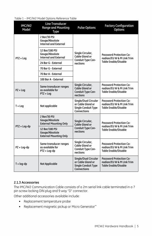
Table 1 – IMC/W2 Model Options Reference Table
IMC/W2 Model
Line Transducer Range and Mounting
TypePulse Options Factory Configuration
Options
PTZ + Log
2 Bar/30 PSI Gauge/Absolute Internal and External
Single Circular, Cable Gland or Conduit Type Con-nections
Password Protection Ca-nadian/EU W & M LInk Trim Table Enable/Disable
12 Bar/180 PSI Gauge/Absolute Internal and External
24 Bar G - External
70 Bar G - External
70 Bar A - External
100 Bar A - External
PZ + LogSame transducer ranges as available for PTZ + Log
Single Circular, Cable Gland or Conduit Type Con-nections
Password Protection Ca-nadian/EU W & M LInk Trim Table Enable/Disable
T + Log Not applicable
Single/Dual Circular or Cable Gland or Single Conduit Type Connections
Password Protection Ca-nadian/EU W & M LInk Trim Table Enable/Disable
PTZ + Log-dp
2 Bar/30 PSI Gauge/Absolute External Mounting Only
Single Circular, Cable Gland or Conduit Type Con-nections
Password Protection Ca-nadian/EU W & M LInk Trim Table Enable/Disable12 Bar/180 PSI
Gauge/Absolute External Mounting Only
PZ + Log-dpSame transducer ranges as available for PTZ + Log-dp
Single Circular, Cable Gland or Conduit Type Con-nections
Password Protection Ca-nadian/EU W & M LInk Trim Table Enable/Disable
T + log-dp Not Applicable
Single/Dual Circular or Cable Gland or Single Conduit Type Connections
Password Protection Ca-nadian/EU W & M LInk Trim Table Enable/Disable

6 | GE Oil & Gas
3 Specification and Details
3.1 Pressure MeasurementThe IMC/W2 is fitted with a pressure transducer, mounted according to requirements. The pressure port is a 1/8” NPT male fitting. The various pressure transducers and associated percentage of accuracy are listed in Table 2 (Pressure Transducer Accuracy Reference Table).
Table 2 – Pressure Transducer Accuracy Reference Table
The transducer burst pressure will exceed transducer range +20% for all the transducers provided.
Pressure Transducer Range Details
2 Bar (30 psi) AIMC/W2 maximum error of 0.4% of reading from 0.8 Bar A to 2.0 Bar A over operating temperature range of -40°F to +140°F (-40°C to +60°C)
2 Bar (30 psi) GIMC/W2 maximum error of 0.4% of reading from 0.8 Bar G to 2.0 Bar G over operating temperature range of -40°F to +140°F (-40°C to +60°C)
12 Bar (180 psi) AIMC/W2 maximum error of 0.4% of reading from 1 Bar A to 12 Bar A over operating temperature range of -40°F to +140°F (-40°C to +60°C)
12 Bar (180 psi) GIMC/W2 maximum error of 0.4% of reading from 1 Bar G to 12 Bar G over operating temperature range of -40°F to +140°F (-40°C to +60°C)
24 Bar (350 psi) GIMC/W2 maximum error of 0.4% of reading from 1 Bar G to 24 Bar G over operating temperature range of -40°F to +140°F (-40°C to +60°C)
70 Bar (1000 psi) AIMC/W2 maximum error of 0.4% of reading from 5 Bar A to 70 Bar A over operating temperature range of -40°F to +140°F (-40°C to +60°C)
70 Bar (1000 pis) GIIMC/W2 maximum error of 0.4% of reading from 5 Bar G to 70 Bar G over operating temperature range of -40°F to +140°F (-40°C to +60°C)
100 Bar (1500 psi) AIMC/W2 maximum error of 0.4% of reading from 5 Bar A to 100 Bar A over operating temperature range of -40°F to +140°F (-40°C to +60°C)
• Replacementbatterypack-eitheralkalineorlithiumoptions
• SpareAllenkeys
• Thermowells-usedforexternaltemperatureonly.
• Pressure/valvepipingkits

IMCW2 Hardware Handbook | 7
3.2 Temperature MeasurementTemperature measurement is performed by a 4-wire Class A 100 ohm platinum resistance thermometer (temperature probe) supplied as an option with the IMC/W2. External temperature probes are available in either a 5 or a 10 foot amoured cable.
IMC/W2 accuracy for temperature is better than 0.5°C (0.9°F) over the temperature range -40°C to 60°C (-40°F to 140°F).
For connection details refer to section 5.5.1.2 (Temperature Measurement (TB2)).
3.3 Volume InputThe IMC/W2 accepts the pulses generated by the Wiegand sensor inserted as an assembly into the magnetic pick up of the Dresser meter. The following flow sensing sequences are operator configurable from within the User Terminal:
• Forward–Reverse.
• Reverse–Forward.
• Reverse.
• Forward.
• Forward+Reverse.
The value of the input pulses depends on the meter size. Dresser meters can be either meter family Series A (LMMA), Series B, Series G or high pressure. There are a number of meter models for both Series A and Series B, and this is operator configurable from within the User Terminal. For further details consult the IMC/W2 User Terminal Manual.
For connection details refer to section 5.5.1.1 (Volume Input (TB1)).
3.4 Pulse OutputThere are 3 isolated Pulse outputs (uncorrected, corrected and fault), and 2 ground terminals. These ground terminals are isolated from the other ground terminals of the IMC/W2. Each output is an open drain connection capable of sinking 10mA and withstanding up to 15 Volts (5 Volts max. above +40°C or +104°F). An external “pull up” resistor or current source is normally required to ensure that the circuit will function correctly. The significance of the pulse outputs are operator configurable from within the User Terminal, and may be set independently for uncorrected and corrected volume to 0.1 / 1 / 10 / 100 / 1000 as required by the operator and as defined by meter type.
The Pulse outputs are connected to a terminal block (TB3) mounted internally and by default provide:
• Uncorrectedvolumepulses.
• Correctedvolumepulses.
• Fault/Alarmindication.

8 | GE Oil & Gas
Figure 1 - (IMC/W2 and Meter Dimension Considerations)
The uncorrected and corrected outputs are isolated from each other (via GND1 (uncorrected) and GND2/3 (corrected)). The fault output shares the GND2/3 ground terminal with the corrected output.
The “ON” duration of the pulses at outputs 1 and 2 may be configured by the user to 62.5mS, 125mS, 187mS or 315mS to suit the driven equipment. The Fault/Alarm (when configured) indication will pulse at approximately 1Hz when a Fault condition is present.
The connection details for the Pulse Output is shown in section 5.5.1.3 (Pulse Output (TB3)) for standard gland connections, as an alternative (order dependent) the Amphenol connection may be fitted.
3.5 Units of MeasurementThe IMC/W2 units are selectable during operator set up and can be set to imperial, metric or a combination of both in the same configuration, for example °C and cu ft. Refer to the IMC/W2 User Terminal Handbook for further details.
3.6 Meter Dimensions

IMCW2 Hardware Handbook | 9
Table 3 - IMC/W2 and Meter Dimension TableM
odel
Dim
ensi
ons
Capa
city
Uni
tC
LM
NO
PR
ST
WX
YZ
8C80
0 cf
hin
18-1
5/32
4-11
/16
13-2
5/32
8-45
/64
66-
3/4
34-
11/1
611
64-
3/4
2-1/
44
22.6
m3 /h
mm
469
119
350
221
153
172
76.5
119
280
153
120.
6537
.54
11C
1100
cfh
in19
4-15
/16
148-
45/6
46
6-3/
43
4-11
/16
116
4-3/
42-
1/4
4
31 m
3 /hm
m48
212
635
622
115
317
276
.511
928
015
312
0.65
37.5
4
15C
1500
cfh
in19
-29/
325-
13/3
214
-1/2
8-45
/64
66-
3/4
34-
11/1
611
64-
3/4
2-1/
44
42.5
m3 /h
mm
505.
513
836
822
115
317
276
.511
928
015
312
0.65
37.5
4
G16
800
cfh
in18
-15/
324-
11/1
613
-25/
328-
45/6
46
6-3/
43
4-11
/16
116
4-3/
42-
1/4
4
22.6
m3 /h
mm
469
119
350
221
153
172
76.5
119
121
153
120.
6537
.54
G25
1412
cfh
in19
-5/6
45-
13/3
213
-43/
647-
7/8
66-
3/4
34-
11/1
64-
3/4
64-
3/4
2-1/
44
42.5
m3 /h
mm
505
138
368
221
153
172
76.5
119
280
153
120.
6557
.54
2M20
00 c
fhin
19-3
9/64
5-21
/32
148-
45/6
46-
31/3
26-
3/4
3-31
/64
4-11
/16
4-3/
46
4-3/
42-
1/4
4
57.0
m3 /h
mm
498
144
355
221
177
172
88.5
119
121
153
120.
6537
.54
3M30
00 c
fhin
20-2
7/32
6-1/
414
-39/
648-
45/6
46-
31/3
26-
3/4
3-31
/64
4-11
/16
4-3/
46
4-3/
42-
1/4
4
85.0
m3 /h
mm
529
159
371
221
177
172
88.5
119
121
153
120.
6557
.54
5M50
00 c
fhin
23-4
5/64
7-11
/16
168-
45/6
46-
31/3
26-
3/4
3-31
/64
4-11
/16
4-3/
47-
1/2
63-
5/16
4
141.
5 m
3 /hm
m60
219
540
722
117
717
288
.511
912
119
0.5
152.
484
.14
4
G40
2295
cfh
in19
-39/
645-
21/3
214
8-45
/64
6-31
/32
6-3/
43-
31/6
44-
11/1
64-
3/4
64-
3/4
2-1/
44
65.0
m3 /h
mm
477
144
334
221
177
172
88.5
119
121
153
120.
6557
.54
G65
3531
cfh
in20
-27/
326-
1/4
14-3
9/64
8-45
/64
16-3
1/32
6-3/
43-
31/6
44-
11/1
64-
3/4
64-
3/4
2-1/
44
100.
0 m
3 /hm
m52
915
937
120
017
717
288
.511
912
115
312
0.65
57.5
4
G100
5650
cfh
in23
-45/
647-
11/1
616
8-45
/64
6-31
/32
6-3/
43-
31/6
44-
11/1
64-
3/4
7-1/
26
3-5/
164
160.
0 m
3 /hm
m60
219
540
722
117
717
288
.511
912
119
0.5
152.
484
.14
4
7M70
00 c
fhin
23-2
5/64
6-1/
216
-57/
648-
45/6
48-
7/8
9-1/
24-
7/16
4-11
/16
4-3/
47-
1/2
63-
1/16
4
200
m3 /h
mm
594
165
429
221
225.
424
1.3
112.
711
912
119
0.5
152.
477
.84
G 16
0-3”
8800
cfh
in24
-7/6
48-
3/16
15-2
9/32
8-45
/64
8-7/
89-
1/2
4-7/
164-
11/1
64-
3/4
97-
1/2
4-1/
328
250
m3 /h
mm
612
208
404
221
225.
424
1.3
112.
711
912
122
8.6
190.
510
2.4
8
G160
-4”
8800
cfh
in24
-7/6
48-
9/32
17-7
/87-
7/8
8-7/
89-
1/2
4-7/
164-
11/1
64-
3/4
97-
1/2
4-1/
328
250
m3 /h
mm
612
211
454
200
225.
424
1.3
112.
711
912
122
8.6
190.
510
2.4
8
11M
11,0
00 c
fhin
26-3
1/32
8-9/
3218
-43/
648-
45/6
48-
7/8
9-1/
24-
7/16
4011
/76
4-3/
49
7-1/
24-
1/32
8
310
m3 /h
mm
685
211
475
221
225.
424
1.3
112.
711
912
122
8.6
190.
510
2.4
8
16M
16,0
00 c
fhin
31-2
1/32
10-5
/821
8-45
/64
8-7/
89-
1/2
4-7/
164-
11/1
64-
3/4
97-
1/2
4-1/
328
450
m3 /h
mm
804
270
534
221
225.
424
1.3
112.
711
912
122
8.6
190.
510
2.4
8
G250
16,0
00 c
fhin
31-3
1/32
10-5
/821
8-45
/64
8-7/
89-
1/2
4-7/
164-
11/1
64-
3/4
97-
1/2
4-1/
328
450
m3 /h
mm
804
270
534
221
225.
424
1.3
112.
711
912
122
8.6
190.
510
2.4
8

10 | GE Oil & Gas
3.7 Serial PortThe IMC/W2 is fitted with an external 7 pin screw locking DIN connector for the serial port connections. Logic levels are 5 – 12V into the IMC/W2 with a 5V nominal output from the IMC/W2 (RS232 / RS232C levels).
NOTE: There are uncorrected volume pulses available on the serial port, which are used for a prover testing of meter accuracy, see section 6 (Accuracy Tests) for further details.
3.8 DisplayThe LCD display is permanently active and operational over the temperature range -40°C to 60°C (-40°F to 140°F).
Depending on the particular model option chosen and the operator’s configuration of the unit, the front panel selector button enables the IMC/W2 to display the following parameters:
• CorrectedVolume • UncorrectedVolume • FlowRate • CorrectionFactor • MeterSize** • LinePressure • Temperature • UncorrectedVolumeUnderFault • CorrectedResidual • UncorrectedResidual • Firmwareversion • AtmosphericPressure* • BasePressure • PressureFactor • Supercompressibility • BatteryVoltage • CurrentDate • CurrentTime • ConfigurableScreens–ThreeadditionalparametersconnectedwithDaily Consumption could be selected from seven options: • AccumulatedCorrectedVolumepreviousday, • AccumulatedCorrectedVolumecurrentday, • AccumulatedCorrectedVolumepreviousmonth, • AccumulatedCorrectedVolumecurrentmonth, • Highestdailyvolumeinthepreviousmonth, • Highestdailyvolumeinthecurrentmonth, • Dateoflastconsumptionalarm. • Differentialpressureresults*Only where applicable, i.e. if transducer is gauge ** IMC/W2’s with a DP transducer fitted will show Differential Pressure in the Meter Size position. Meter Size is displayed on an alternate screen.

IMCW2 Hardware Handbook | 11
It is possible to specify which parameters are displayed on the LCD and which param-eter is displayed by default. When shipped, the IMC/W2 will display all parameters with the Corrected Volume being default.
In alarm and / or fault conditions a message is displayed on the LCD indicating the nature of the alarm and / or fault, see table 4 (LCD and Alarm Conditions). For further information regarding the LCD consult the IMC/W2 User Terminal Handbook.
Table 3 – LCD and Alarm Conditions
LCD Alarm Code Alarm Condition Additional Symbols Displayed
HP AL High Pressure alarm N/A
LP AL Low Pressure alarm N/A
Ht AL High Temperature alarm N/A
Lt AL Low Temperature alarm N/A
HF AL High Flow alarm N/A
LF AL Low Flow alarm N/A
D_In_Al / tAnnPEr Digital Input/Tamper Alarm N/A
vol AL High Consumption Alarm N/A
dP AL** Meter DP Alarm N/A
LCD Fault Code Fault Condition Additional Symbols Displayed
Lo bAtt Low Battery Battery icon
P FLt Pressure Fault Alarm Bell Icon
t FLt Temperature Fault Alarm Bell Icon
Int FLt Internal Operations Fault Alarm Bell Icon
OS FLt Ovespeed Fault Alarm Bell Icon
Pm FLt** DP Transducer Fault Alarm Bell Icon
dP FLt** Meter DP Fault Alarm Bell Icon
dp LOC** Meter Lockup Fault Alarm Bell Icon
dP ZErro* Meter DP Zero Lockup Fault Alarm Bell Icon
3.9 MemoryThe IMC/W2 has non-volatile memory and upon battery failure, will retain all of the totals obtained within the last hour of operation and all set up data. These will be available and ready for use as soon as power is restored.
Data logs (order dependant) are continually stored in the memory; the total number of logs depends on the configuration of both the log parameters and logging periods, a data log may contain any of the following information:
• CorrectedVolume
• UncorrectedVolume
** NOTE: Available only on IMC/W2 units fitted with a Differential Pressure Transducer.

12 | GE Oil & Gas
• CorrectionFactor • UncorrectedVolumeUnderFault
• AverageCorrectedFlowRate
• PeakCorrectedFlowRate
• Supercompressibility • MinimumPressure • MaximumPressure • AveragePressure • EndingPressure • MinimumTemperature • MaximumTemperature • AverageTemperature • EndingTemperature • BatteryVoltage
For further information regarding the data logs consult the IMC/W2 User Terminal Handbook.
3.10 Internal SupplyThe IMC/W2 is powered by an internal alkaline (nominal life of 5 years) or optional lithium (nominal life of 15 years) battery pack. The actual length of the battery life will depend on the conditions of use. The state of the battery is monitored and a low battery alarm is given at least 2 months before the batteries are exhausted. It is recommended that the front panel selector button is pressed before changing the battery (see section 7.1 (Replacing the Battery Pack)).
Short term power is supplied via super capacitors to allow the unit to continue to function during battery replacement.
NOTE: Change battery type and clear any faults or alarms in MCUT application.
3.11 EnvironmentThe IMC/W2 may be operated over the following ranges:
Temperature -40°C to 60°C (-40°F to 140°F).
Humidity 0 – 95% (condensing).
EMC EN50081-1 and EN50082-2 Meets FCC class B requirements.
Ingress IP66 and NEMA 4X for dust and water penetration, i.e. fully weatherproof.

IMCW2 Hardware Handbook | 13
4 SafetyThe IMC/W2 is intrinsically safe. Class 1, Div. 1, Group A, B, C, and D locations.
Canadian Standards Association (CSA) approval number 1224451
5 Installation5.1 UnpackingThe following items are supplied with the IMC/W2:
Quantity
IMC/W2 Handbook 1
3mm hexagon wrench (Allen key) 1
Spacer 4
M4 x 20 cup fixing screw 3
Calibration certificate 1
The User Terminal is supplied with an additional handbook for guidance on use of the software. This is included on the User Terminal CD.
5.2 Safety RequirementsIMC/W2 installation must meet Intrinsic Safety requirements, as stated in section 4 (Safety), before beginning installation. It is essential to follow any National Codes of Practice dealing with Intrinsically Safe installations. All Intrinsically Safe circuits must be segregated from non-I.S. circuits. The transducers in the IMC/W2 are intrinsically safe.
In line with our Intrinsic Safety Certifications, the IMC/W2 must only be powered by an approved GE battery pack.
Connection of any non intrinsically safe equipment must be properly assessed by the user. The manufacturer (GE) will not take responsibility for the overall safety of the system.
For commissioning and reading data the serial port may also be connected to a lap top computer under the following conditions:
• Laptopcomputers,generally,arenotintrinsicallysafe.Therefore,before using an uncertified laptop in the hazardous area, a gas test should be performed to prove that no potentially hazardous gas mixture exists in the area. If this is not possible the lap top must not be used in the hazardous area.
• Thelaptopcomputermustbepoweredbybatteriesaloneandthesemust be incapable of supplying more than 25 Volts. No connection is to be made to an external supply (e.g. charger) even if non-operational. (The presence of the connection can itself create a hazardous condition).
The temperature probe is only suitable for use at atmospheric pressure and therefore must be used in conjunction with a thermowell which is capable of withstanding the line pressure.
All individual wires connected to the circuit board must have at least 0.25mm (1/100 ins) of insulation.

14 | GE Oil & Gas
5.3 EMC CompatibilityTo ensure that the performance specifications are not significantly affected by electromagnetic interference, it is essential that:
• Allconductorsareadequatelyshieldedusingbraidedscreensandthat these screens are terminated as recommended in this manual.
• Exceptwherestatedotherwise,thelengthofexternalconnectionsshould not exceed 3m (9.57ft).
• Ifequipmentwhichisnotapprovedbythemanufacturer(GE)isconnectedto the IMC/W2, it is the operator’s responsibility to ensure that this equipment is installed and operated in a manner which will ensure that the system is compliant with the relevant EMC standards.
• Forprotectionsagainststaticdamage,itisessentialthatanti-static precautions are taken when the IMC/W2 is opened for installation or maintenance.
5.4 Mechanical InstallationThe IMC/W2 is mounted directly to the meter; see Figure 2 (IMC/W2 Meter Mounting Guide). Consult the factory for further installation instructions of IMC/W2 to meter body (request 056684-000 BLLN Field Installation IMCW2-To-MTR).
Figure 2 – IMC/W2 Meter Mounting Guide - Series B
Figure 2 – IMC/W2 Meter Mounting Guide - Series A

IMCW2 Hardware Handbook | 15
5.4.1 Setting the Weights and Measures LinkIf the IMC/W2 is fitted with a weight and measure jumper, operator configuration is required to set up the unit the read/write link will need to be switched to the Read/
Write position. To set the Read/Write link:
1. If the IMC/W2 is in a hazardous area the setting of the Weights and Measure Link should NOT be carried out as the PCB protection plate is removed. The set up procedure should be carried out prior to installation.
2. Remove the 4 screws securing the IMC/W2 front using the 3mm hexagon wrench (Allen key) supplied. If the 3mm hexagon wrench is not available a 7/64 ins wrench will work but may “cam out” (strip) the head making future loosening and tightening difficult.
3. Lift the front panel forward to expose the PCB protection plate that covers the main circuit board.
4. Remove the 2 PCB protection plate retaining screws (breaking the Weights and Measures seal).
5. Identify the Read/Write protection link; remove from the Read Only position and replace in the Read/Write position. Refer to Figure 3 (Setting the Weights and Measures Link).
6. The necessary parameter changes should now be carried out via the User Terminal (for further information consult the IMC/W2 User Terminal Handbook).
7. Once the necessary parameter changes have been uploaded to the unit remove the Read/Write link from Read/Write position and replace in the Read Only position.
8. Replace the 2 PCB protection plate retaining screws. Any required seal must be replaced by the appropriate authority before re-closing the unit. Normally the unit should be set up before sending it to the approval authority for the first time.
9. The IMC/W2 front panel should be offered up to the case checking that no wiring is trapped between the panel and body.
10. Reinstall the 4 front panel fixing screws and tighten these a little by hand until all screws are started. Use of anti-seizing compound is recommended.
11. Carefully hold the front panel against the body to form the seal and tighten the 4 securing screws using a 3mm hexagon wrench (Allen key). Ensure that the cables are retained within the enclosure and are not trapped in the lid seal.

16 | GE Oil & Gas
Figure 3 – Setting the Weights and Measure Link (Hardware Link).

IMCW2 Hardware Handbook | 17
5.5.1 Location of the Connection TerminalsWhen the IMC/W2 case is opened, the location of the connections terminals will appear as in Figure 4 (Location of the Connection Terminals):
1. Remove the 4 screws securing the IMC/W2 front panel using the 3mm hexagon wrench (Allen key) supplied. If the 3mm hexagon wrench is not available a 7/64 ins wrench will work but may “cam out” (strip) the head making future loosening and tightening difficult.
2. Lift the front panel forward to expose the PCB protection plate.
3. Carry out the electrical installation as required (refer to sections 5.5.1.1 Volume Input (TB1), 5.5.1.2 Temperature Measurement (TB2) and 5.5.1.3 Pulse Output (TB3), and once complete the IMC/W2 front panel should be replaced and secured:
4. Ensure that no wiring is trapped between the panel and body prior to reinstalling the front panel.
5. Reinstall the 4 front panel mounting screws and tighten these a little by hand until all screws are started. Use of anti-seize compound is recommended.
NOTE: If the case is to be wired and sealed by the Weights and Measures authority, the 4 spacers supplied should be fitted under each head of the lid securing screws so that the wiring holes are accessible when the screws are fully tightened.
6. Carefully hold the front panel against the body to form the seal and tighten the 4 securing screws using a 3mm hexagon wrench (Allen key). Ensure that cables are retained within the enclosure and are not trapped in the lid seal.
5.5 Electrical InstallationElectrical installation should be performed by a person competent and knowledgeable about installation of intrinsically safe equipment and totally conversant with the National Code of Practice.
For protection against static damage it is essential that anti-static precautions are taken when the IMC/W2 is opened for installation or maintenance.

18 | GE Oil & Gas
Figure 4 – Location of the Connection Terminals

IMCW2 Hardware Handbook | 19
5.5.1.1 Volume Input (TB1)The mag well should be connected to the W1, W2/REED and GND Volume Input terminals of TB1, as shown in Figure 5 (Volume Input (TB1) Connections).
Figure 5 – TB1 Connections

20 | GE Oil & Gas
5.5.1.2 Temperature Measurement (TB2)The temperature measurement is accomplished via a temperature probe. Current is injected through a pair of connections and the voltage measured across the other pair.
The wires should be connected to the PRT/RTD Probe terminals of TB2, as shown in Figure 6 (Temperature Transducer Connections).
There are 2 pairs of wires which are essentially connected directly together inside the probe. A wire from each pair must be connected to the “I” terminals and the other wire from the same pair to the corresponding “V” terminal.
Figure 6 – Temperature Probe Connections (TB2)

IMCW2 Hardware Handbook | 21
5.5.1.3 Pulse Output (TB3) Figure 7 [Pulse Output Connection (TB3)] shows the connections for the pulse output. Other GE approved product, such as the Chatterbox (isolation unit) may be connected to the pulse outputs. Any equipment connected to the pulse output must be individu-ally assessed to ensure that the system is safe. The manufacturer (GE) will not take responsibility for the overall safety of the system.
Figure 7 – Pulse Output Connections (TB3)
6. Accuracy TestCombined accuracy test of a gas meter with IMC/W2 can be performed as described in Dresser publication: Installation/Operation/Maintenance Manual IOM: Smart Prove.
7. MaintenanceThere is no requirement for routine maintenance of the IMC/W2. A pressure check may be performed by applying a known test pressure to the pressure transducer and reading the pressure value from the front panel display of the IMC/W2. The error as a percentage of reading should be calculated as follows:
100 x ( (Pind – Ptrue) / Ptrue )
Where Pind is the indicated pressure reading on the display and Ptrue is the known measured pressure. Any difference should be less than 0.7% or such other value defined by local Weights and Measures requirements (for Ptrue higher the 20% of full scale). If this value is exceeded the IMC/W2 should be returned to the distributor so that the cause of the inaccuracy may be investigated. For further details refer to section 7.2 (Pressure Transducer Recalibration).

22 | GE Oil & Gas
The temperature calibration may also be performed by immersing the temperature probe into a container of liquid of a known temperature. For further details refer to section 7.3 (Temperature Transducer Recalibration).
7.1 Replacing the Battery PackIf the low battery indication is active, the battery pack should be changed within the next 2 months.
IMC/W2’s should not be left with discharged packs inside them as discharged cells are more prone to leak than are new or partially used cells. If the IMC/W2 is to be stored for any length of time, the battery pack should be removed and stored separately.
If the internal battery voltage is low, the battery icon will be displayed when the front panel button is pressed. The icon will be present until display test is selected or the default corrected total display is set or the battery voltage rises above the low thresh-old. NOTE: The low battery fault latch will only be set when the battery voltage has been low for 24 consecutive hours.
Before replacing the battery pack press the front panel selector button on the IMC/W2. This operation ensures that the latest corrected and uncorrected totals are stored in the permanent memory of the IMC/W2. Super capacitors will maintain normal operation of the unit during battery replacement.
For protection against static damage, it is essential that anti-static precautions are taken when the IMC/W2 is opened.
The battery pack affects the intrinsic safety of the IMC/W2 and must be replaced with the correct Dresser battery pack. To replace the battery pack:
1. Press the front panel selector button on the front of the IMC/W2.
2. Unscrew the 4 screws holding the front panel of the IMC/W2 using a hexagon wrench or suitable Allen key (as described in section 5.5 Electrical Installation).
3. Unplug the battery connector from the main circuit board mounted behind the front panel.
4. Use a screw driver to remove the 4 screws (and 4 washers) holding the battery pack.
5. Remove the old battery pack.
6. Place the new battery pack in to position and replace the 4 screws and 4 washers.
7. Plug the new battery pack into the main circuit board, such that the battery plug engages correctly with the connector locking ramp on the circuit board.
8. Check that the IMC/W2 displays the default parameter of the LCD and the normal operation has resumed.
9. Carefully dress the battery lead and the other wirings so that they will not be trapped between the enclosure and front panel.
10. Replace and retighten the screws holding the front panel as described in section 5.4 Mechanical Installation.
NOTE: Observe any local regulations on disposal of the battery pack.

IMCW2 Hardware Handbook | 23
7.2 Pressure Transducer CalibrationRecalibration of the pressure transducer should not be required however, the IMC/W2 may be pressure calibrated by the operator, using the serial port of the IMC/W2 and the User Terminal software. It is possible to calibrate either the zero only or both the zero and the span.
NOTE: During the pressure calibration process multiple temperature readings are automatically compared over a period to ensure that the readings are stable. If stability is not obtained the calibration process will not be successful.
For further details regarding the pressure calibration refer to the IMC/W2 User Terminal Handbook.
7.3 Temperature CalibrationTemperature recalibration should not be required however, the IMC/W2 may be temperature calibrated by the operator, using the serial port of the IMC/W2 and the User Terminal software.
To obtain temperature calibration points use one of the following methods:
Use temperature controlled baths with the IMC/W2 temperature probe and a calibrated thermometer for determining the bath temperatures. As an alternative use a vacuum flask filled with liquid which is well stirred, and place the temperature probe and calibrated thermometer in this.
OR
Simulate the temperature probe using a calibrated resistance box set to values cor-responding to 2 different temperatures. If this option is chosen the temperature probe must be disconnected from the IMC/W2 and the resistance box must be connected as a 4 wire resistor in its place.
NOTE: During the temperature calibration process multiple temperature readings are automatically compared over a period to ensure that the readings are stable. If stability is not obtained the calibration process will not be successful.
For further details regarding the temperature calibration refer to the IMC/W2 User Terminal Handbook, alternatively contact your distributor.
7.4 Restoring Factory DefaultsIt is possible to restore the factory defaults for pressure and temperature from within the User Terminal Manual.
7.5 ServiceThere are no user replaceable parts with the exception of the temperature probe and the battery pack.
Repair of the circuit board itself should not be attempted as this may invalidate I.S. approval of the product.
NOTE: If the battery is changed then be sure to change the battery type (akaline or lithium) by connecting with serial cable and MCUT application (Figure 8).
Figure 8 – Battery Type

GEA20177 Model IMC/W2 Hardware Manual 6.2014
GE Oil & Gas 16240 Port Northwest Drive, Ste. 100Houston, TX 77041T: +1 832.590.2303 Inside US T: 800.521.1114F: +1 832.590.2494 Inside US F: 800.335.5224
Visit us online at: www.ge.com/energy
©2014, General Electric CompanyAll Rights Reserved* Trademarks of General Electric Company.