drawings of rural water supply and sanitation modules
TRANSCRIPT

LIBRARYINTERNATIONALFOR COMMUNITY
IIUC1
CHHTR1MM
o
Drawings of Rural Water Supply and SanitationModules
unicef

ITEM
1.
2.
3.
4.
5.
6.
LOW COST RURAL WATER SUPPLIES AND SANITATION
DRAWINGS
INDEX
1
ITEM
7.
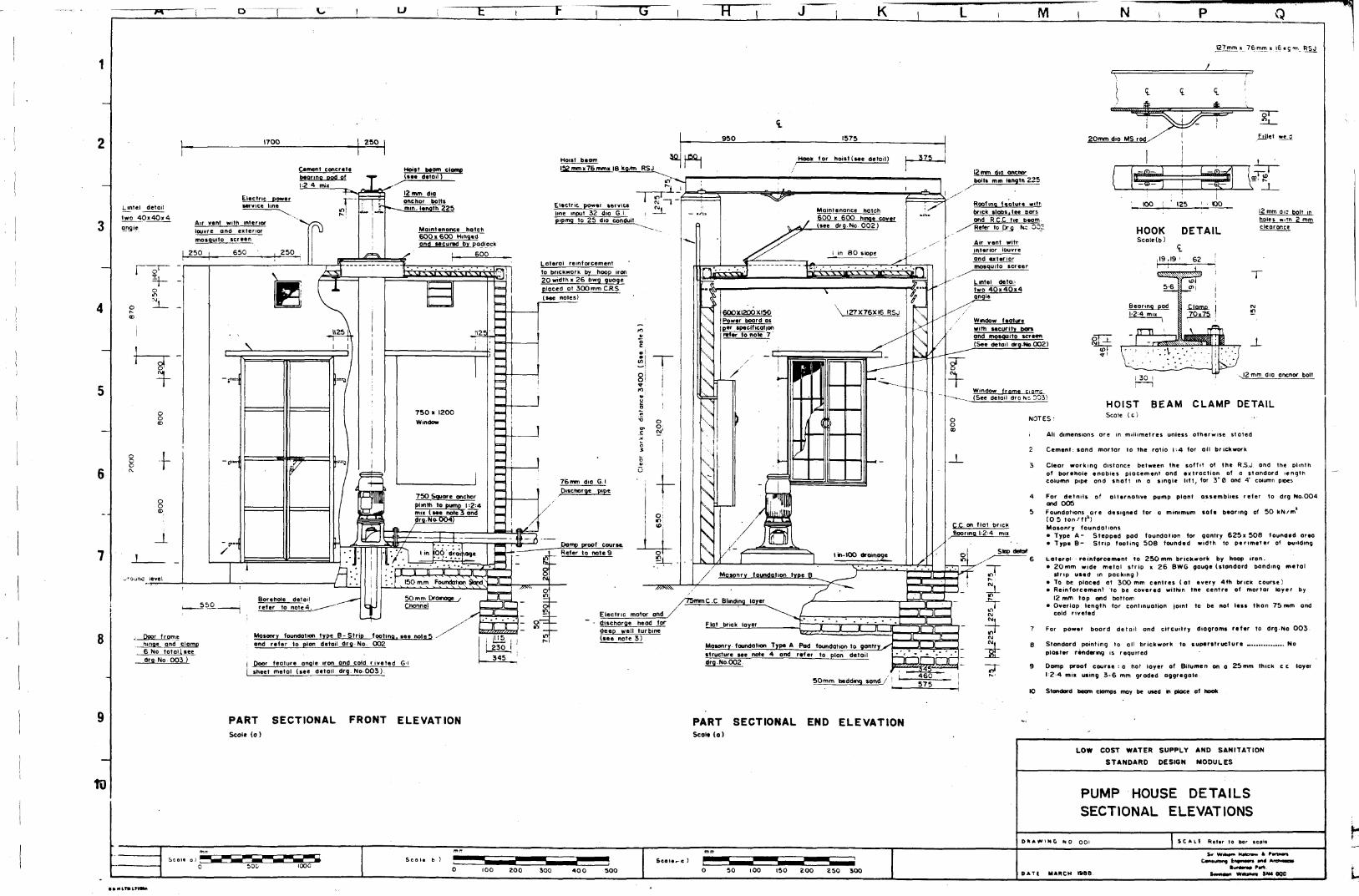
PUMP HOUSE
Sectional ElevationsPlan and RoofingPower Board and Misc. DetailsDetail: Deep Well TurbineDetail: Single Stage CentrifugalBooster Pump Assembly Details-Multi Stage Centrifugal
GROUND LEVEL STORAGE TANK
Tank/Booster Pump Bay - General Arrangement11.4 Cubic Metre (2500gal) G L Tank
Reinforcement Details (1 of 2)Reinforcement Details (2 of 2)
22.8 Cubic Metre (5000gal) G L TankReinforcement Details (1 of 2)Reinforcement Details (2 of 2)
34.1 Cubic Metre (7500gal) G L TankReinforcement Details (1 of 2)Reinforcement Details (2 of 2)
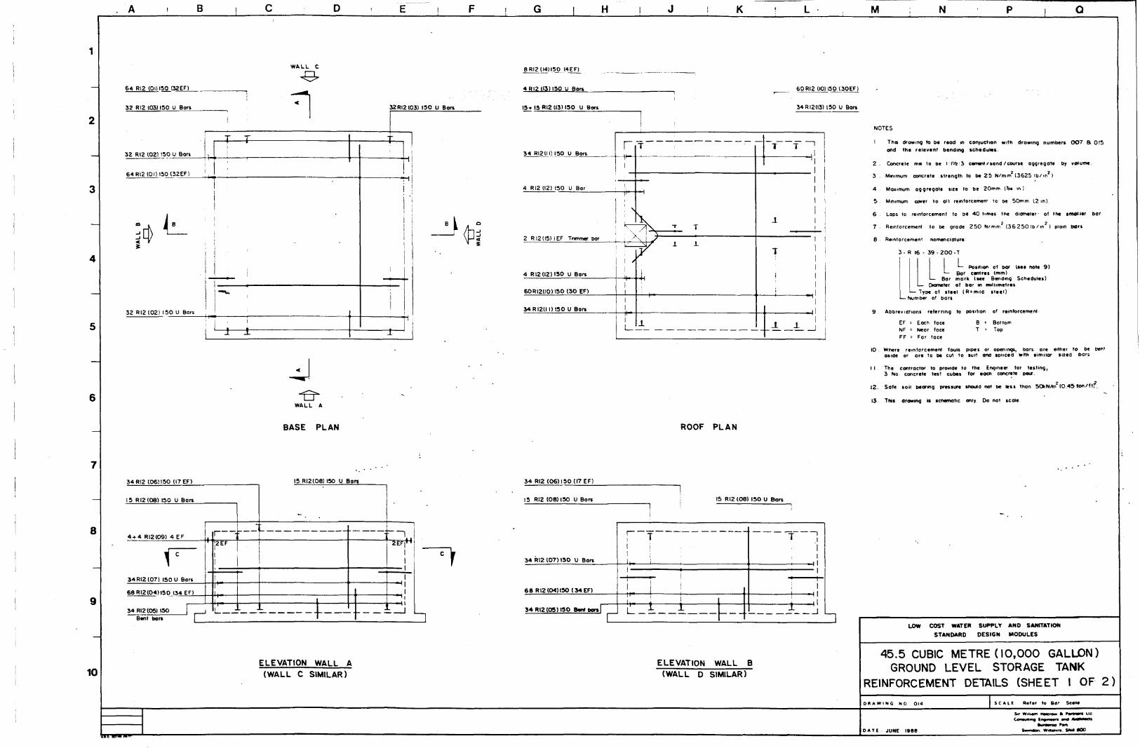
45.5 Cubic Metre (10,000gal) G L TankReinforcement Details (1 of 2)Reinforcement Details (2 of 2)
68.3 Cubic Metre (15,000gal) G L TankReinforcement Details (1 of 2)Reinforcement Details (2 of 2)
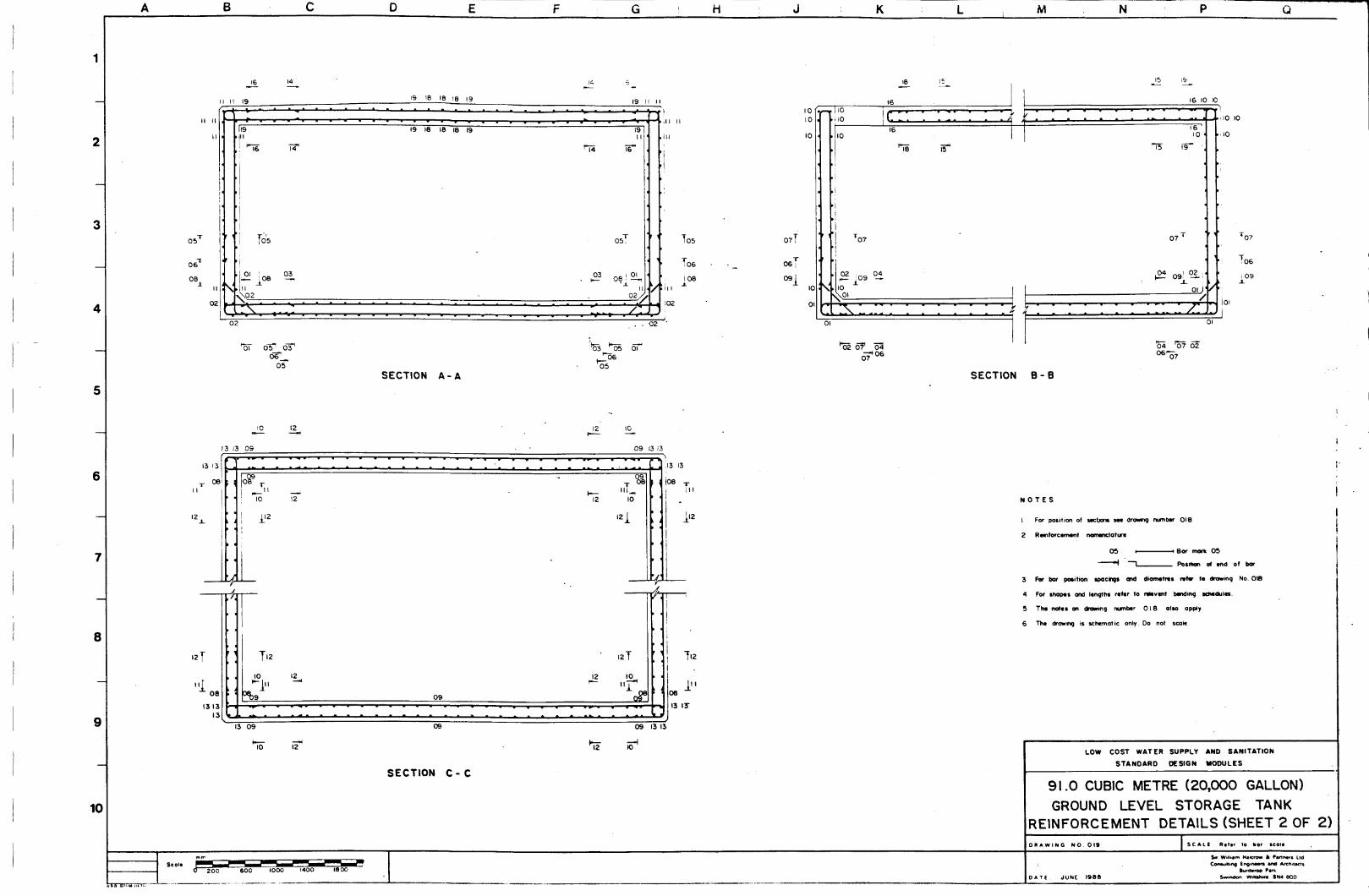
91.0 Cubic Metre (20,000gal) G L TankReinforcement Details (1 of 2)Reinforcement Details (2 of 2)
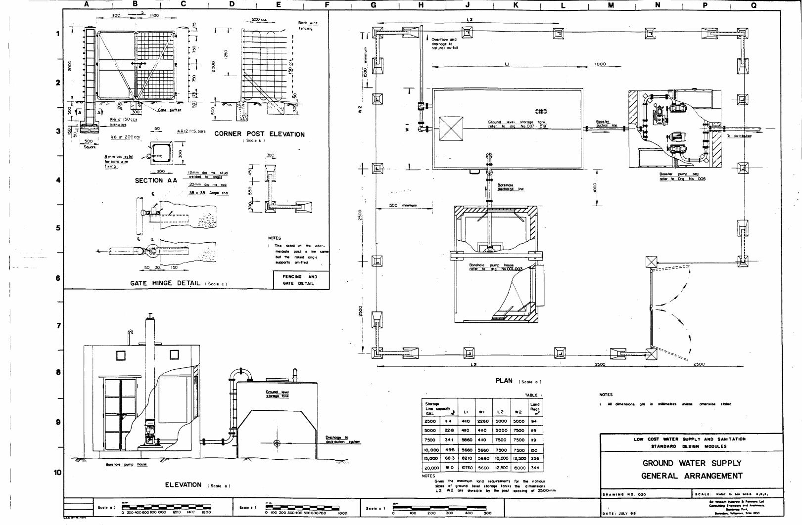
GENERAL ARRANGEMENTS
Ground Water SupplyCanal Intake Surface Water Supply
INFILTRATION GALLERY AND INTAKE STRUCTURE
Infiltration GalleryCanal Intake Structures
HORIZONTAL ROUGHING FILTER
General Arrangement
PRE-SEDIMENTION BASIN
Plan and Sectional Views
Sections and Inlet/Outlet Pipe Detail
DRAWING NO.
001002003004005
006
007
008*009*
010*Oil*
012*013*
014*015*
016*017*
018*019*
020021
022023
8.
9.
10*1"': i - v '"•
\ LO:024
025026
DRAWING NO.
SLOW SAND FILTER
General Arrangement - 25 sm AreaGeneral Arrangement - 50 sm AreaGeneral Details and Information25sm Reinforcement Details (1 of 2)25sm Reinforcement Details (2 of 2)50sm Reinforcement Details (1 of 2)50sm Reinforcement Details (2 of 2)
CLEAR WELL
Clear Well/Booster Pump Bay - General Arrangement11.4 Cubic Metre (2500gal) Clear Well
Reinforcement Details (1 of 2)Reinforcement Details (2 of 2)
22.8 Cubic Metre (5000gal) Clear WellReinforcement Details (1 of 2)Reinforcement Details (2 of 2)
34.1 Cubic Metre (7500gal) Clear WellReinforcement Details (1 of 2)Reinforcement Details (2 of 2)
45.5 Cubic Metre (10,000gal) Clear WellReinforcement Details (1 of 2)Reinforcement Details (2 of 2)
68.3 Cubic Metre (15,000gal) Clear WellReinforcement Details (1 of 2)Reinforcement Details (2 of 2)
91.0 Cubic Metre (20,000gal) Clear WellReinforcement Details (1 of 2)Reinforcement Details (2 of 2)
STANDARD DRAWINGS
Community Tank and Stand Post DetailTrenching DetailsValve and Chamber DetailsImproved Dugwell - Twin Hard Pump AssemblyHand Pump Assembly on TubewellImproved Dugwell - Single Hand Pump AssemblySpring Capping DetailBreak Pressure Tank Detail
SANITATION
Ventilated Improved Pit LatrineTwin Pit Pour Flush Latrine
027028029030*031*032*033*
034
035*036*
037*038*
039*040*
041*042*
043*044*
045*046*
047048049050050A051052053
054055
NOTES
1. All drawings marked with * have associated Bending Schedules at the endof this -volume.
2. All drawings should be read in conjunction with the accompanyingSpecification and Bills of Quantitites.
u ~W K IVI N Q
. T6.15.rn *_ RSJ
U50,
1 1
950
Hook/
(or
1575
hoist (see detail) 375
12 mm dio onct«rbolts mm lengtn 225
Hont b«or52mmi76mmi IB kCement concrttt
beorino pod of1-2 4 mi«
Hoist Warn dome(• • • detoil)
12 mm dioonchor boltsElectric power
service line Roofing feature witrbrick slobt.tee Barsond R.C.C tie beomRefer to pro Kc 002
Electric power serviceline input 32 dio Gpiping to 25 dio conduit
Maintenance hatch600 > 600 hinoe cover
/ (see drg.No 0 0 2 )Air vent with interiorlouvre and exteriormosq
Mointenonce notch6 0 0 » 600 Hingedand secured by padlock Air vent witr
interior louvreond exteriomosquito screerLoterol reinforcement
to brickwork by hoop iron20 width » 26 bwg quoqeplaced at 300 mm CRS(see notes)
Lintel detofwo_40»40«4
le
\ 127X76X16 RSJWindow featurewith security porsond mosouito screen(See detail Org-No 002)
Window frame ciarr.c(See deloil drg He 503)
76mm dig G.IDischarge pipe
750 Square onchorpi mth to pump 1-2:4mn (see note 3 and
No 004C.C on flat brickflooring. 1=2:4 mit
Pomp proof course.Refer to note 9
Masonrv foundation tvoe B150 mm Foundation 9dnd
50 mm DronoqeChannel
Borehole detoirefer to note 4
/75mmC.C Blinding loyer
Flat brick layerElectric motor onddischorge head fordeep well turbine(see note 3 )Mosonry foundation type B- Strip footing, see note5
ond refer to plon detoil drg No 002Door fromehinge ond clomp6 No totollseedrq No 003 )
Mosonry foundofion Type A Pod foundation to gontry><structure see note 4 and refer to plon detoil
Door feature angle iron ond cold riveted 6-1sheet metal (see detail drg. No 0 0 3 )
50mm beddg>q tond /
20mm dio MS rod
HOOKScale(b)
DETAIL
19,19 1 62
5 6
Beormq pod
i^m^
- IT Tl :
• ''•' \'-
I
Clamp70x75
——
j
!
rr
J-
i _L
I 30 12 mm did ancnor bolt
HOIST BEAM CLAMP DETAILNOTES: S c O l E U )
< Alt dimensions ore in millimetres unless otherwise stated
2 Cement: sand mortar to the ratio 1 4 for oil brickwork
3 Clear working distance between the soffit of the R.S.J ond the plinthof borehole enables placement ond extraction of a standard >engthcolumn pipe ond shaft in a single lift, for 3"0 ond A" column pees
For details of alternative pump ptont assemblies refer to drg No.004and 005
5 Foundations ore designed for a minimum safe bearing of 50 kN/m(0 5 ton/ft1)Masonry foundations• Type A- Stepped pod foundation for gantry 6 2 5 x 5 0 6 founded areo• Type B- Strip footing 506 founded width to perimeter of (wilding
6 t«fero4- r«inforcem*nt to 250mm brickwork by hoop iron.• 20mm wide metal strip x 26 BWG gouge (standard banding metol
strip used in packing )• To be placed at 300mm centres fat every 4th brick course)• Reinforcement to be covered within the centre of mortar loyer by
12 mm top ond bottom• Overlap length for continuation joint to be not less than 75 mm ond
cold riveted
For power boord detail ond circuitry diagrams refer to drg No 003
6 Standard pointing to all brickwork to superstructure No
plaster rendering is required
9 Damp proof course : a hot loyer of Bitumen on o 25mm thick cc layer
12 4 mix using 3*6 mm groded aggregate
Standard beam damps may be used in place of hook
TO
PART SECTIONAL FRONT ELEVATIONScole ( a )
PART SECTIONAL END ELEVATIONSeal* (o)
LOW COST WATER SUPPLY AND SANITATION
STANDARD DESIGN MODULES
PUMP HOUSE DETAILSSECTIONAL ELEVATIONS
O « « * i » C NO SCALE Rct*r to bar teolft
SOO ISO 200
Sir Wil|i»m Malcrvw ft
DATC MARCH isaeI M n t Part
SIW0QC

xr TT K M N
8
10
Power board asper tpeciticottor,refer to Drg 003 Cork pock joint
or approved type
Dtesel engine whouitpip* outlet * pipe diawotT clearance of 20mm !
iort 3 0 0 wide by
\\\\\Y\\\\;—i -:Sr-!=. i 1-r
Diesel engineallocated spacerefer to DrgNc0 0 4 , 0 0 5 forpump assemblyoptions
80mm Dig G.I Dischorge pipenkto ground level storge ta
refer to drg No 0 2 0
750 mm sq AnchorPlinth to pumpassembly 1 2 4 mi»refer toDrq. 0 0 4
Sinp footinq.for type B detail
to drg No.OQI
Qpntry column ond foundationFor type A detail r_*fer to
rgNoOOlDoor 90QK 2000 HtSee detoit drg No 001
PART SECTIONAL PLANScole (a )
Roofing Tie beam mainReinforcement4«I2mm dio M.S rods
4 5 - 4 0 . 5 - 6 Tee borsSupporting roofing ttricfc
Rooting brick300 «150 « 40
150
Depth of RCCIRoofma Tie beamjfo perimeter ofI buitdino
Roofing Tie b«omNommol linkReinforcement:6 mm dig M.S rodot 250 centres
ROOFING SLAB SECTIONAL DETAIL RSJ 8 BEARING PADS c a l e < c )
115
ROOFING DETAIL WALL SUPPORTScale (c)
Roof screed
cemeni concrete
Roofing bncl-
300 '150 .40RCC Roofing Tie beam(See woll support detail)
315T«t bar centres
Jt: 1 - i • • • • • • • • r • :• . - • • • • • • • •\IKA\\
45«40«S6 Tee bar ,
127mm x 76mm K 16 kq/m RSJ
ROOFING DETAILRSJ BEARING PAD SECTIONScale ( c )
155 CRS
r
65 J - -65.in
J_ .
I_
i i
-4--U-Roofing brick300^150x40
Maintenance Hatch600 sq.Refer to
detail drowinq No-003
4 5 x 4 0 * 4 6 Tee bars^Supporting Rooting brick
127mm x76mmx t6Ko/m RSJ
ROOFING DETAIL PLANScole (b)
NOTES-
All dim en* ion* are in millimetres unless otherwise stated
2. In case of no electric power supply t the power board as per specification isstill included in the pump house requirements, ready for future connection asand when supply is giver
3 In calculating the minimum floor dimensions of the pump house, provision hosbeen mode for ;the space required for. standby or primary, diesel drive
4. For diesel installation ttte evhaust pipe is to be adequotety logged andpassed through an opening in the wall giving a clearance of 20 mm.around the pipe
LOW COST WATER SUPPLY AND SANITATION
STANDARD DESIGN MODULES
PUMP HOUSE DETAILS
PLAN AND ROOFING
DRAWING NO 002 SCALE Refer to bar icvltf (a),(b],|c).
Scol.(b)1500
DATE FEB IMS
fer WMtm MMetv« ft PmrwmnEn•uc
« « M SN4 000

D H K L . M N Q
8
9
10
-d
BOOSTERPUMPMOTOR
ft
•c
"0TO" E&LI
STAR / DELTA CIRCUIT DIAGRAM
DIRECT ON LINE CIRCUIT DIAGRAM
LEGEND
Clomp position onchoredinto won (see detoil)
2 0 x 2 0 Angle iron Iron*wMh 16 BWG »hetI metqLpanel cold riveted
O;O
-1-
PHASE INDICATOR LAMK
V04UH0LEISOLATORSWITCH
TANK LOWLEVELRELAY
•OREHOLE
ELCCTROOE
L C V E L K L A YTANK HIGH
LEVEL RELAY
1 1
BOOSTCR
ISOLATOR
SWITCH II
BOREHOLE
sum® ©S1WT® ©
STOP
STOP
BOOSTER PUMP
600
BOARD DETAIL SCGK t, >POWERNOTE
Double locking doors with appropriate holes forindicator lamp viewno,
[25 1 75I mm mm
CLAMP DETAILScale d )
DPC
SPC
OR
TR
LC
OC
H / S
LLFS
TT.R
LCT
I-
-i
•<
Ddta prme corlactor
Star phase contactor
Over load relay
Timer relay
line contactor
Oner load contact
Kan I M I float t w i t *
Low level float switch
l a n k l M l ntkiy
L^Fv control troftsiDrfvsf
Control fine
^wer fuse
Level contod
Push button - stop
Push button - stvt
m
BE
RM
®
Da
i
T L
Power on vftOvCQtor
Borehole etediDdc
Rising main
Ampmcicr
Conirol link
Link
Switch
TubeltaM
G* sheet me tot22 BWG qugqc_riveted to «tUx40x4Qonqle trp~~
r
G I sheet meto'gouge 22 BWG
2 0 K 6 tupportinqflat meial tugfillet welded tobotch cotior, onfour sides
MAINTENANCE HATCH DETAIL Scoie o
Fillet weld
DOOR HINGE S CLAMP DETAIL scoie
Stondore putty
T100 lCO crs
. ^ Ifll 25" 4 Flot metqifrominq securityHOT?
WINDOW HINGE a CLAMP DETAIL scale t)
NOTES
I. AM dimensions ore m millimetres unless other* stated
2. This booster arrangement has no pressure control on the presumptan that the pumpwill be manually enarqised at the start of the demond period and manuallyde-energised before demand drops to below 10 V. of peak.Under other conditionso preuur* control switch #wUd be incorporated.
3 Level control transformer voltage ratio to be selected to suit level relays
4 For positioning of boord, refer to pump house details drawingnumbers 00) and 0 0 2
5 DinKt on line a re u it is replaced by Star/ Delta circuit for motorof 5 HP ond over .
6. A scporole transformer is requited lor motors over 10 HP.
7. Dree! on line ond star delta circuits may be combrted if only onemotor requrment is above 5 H P .
8 For surface water schemes only refer 1o booster pump etement circuitdiagrams.
LOW COST WATER SUPPLY AND SANITATION
STANDARD DESIGN MODULES
PUMP HOUSE DETAILS
POWER BOARD AND MISC. DETAILS
D R A W I N G N O 0 0 3 S C A L E R e f e r t o tor fteoic Q,V,Z,C
0 2C 40 60 BO 100 120 140 100 200
Scoie c )Srr Wttiam Haicrowt l i Pifincrt Ltc
Scoie d) i
50 100 150 200 DATE JUNE SB9BunMrop Park.
Swrmtfon Wilttl»r«. SN4 0 0 0

D H M N Q
5
7
Electric dfivnDeep well turbinePuny ossembly
I I575Qmm squoreAnchor plinth toPump ossembly I 2 <
mix
Cork poc>t )otnfor approved alternative
50dip x 2 0 0 long pocketstor pump holding down bolts(positioned according* todoto from pump manutoclurer)
SECTIONAL SIDE ELEVATION
Electric driven Anchor plinthto pump ossemblyI - Z - - 4 C C mi»
8
Deep well turbinePump oftsembly
80mm Dig FlongedGl Pipe
Mm Flange Dip . 20mmWall opening
/ R e f e r to see note 3
Temporary pockingto woll pipe covity /
(Refer to Drg No005)
PLAN VIEW
10PUMP ASSEMBLY P- l
ELECTRIC MOTOR COUPLING
Sell woterLubncotmgTorSlseVnote 2 )
Diesel engine
E«hou»t
80 mm Dig FlangedGl Discharge pipe
SECTIONAL SIDE ELEVATIONExhaust pipe extendedout51de of pump houseo.Qd_ adequately logged
Diesel pump/500 75O square ^
pack joint orapproved oltemotive PLAN VIEW PUMP ASSEMBLY P - 2
DIESEL ENGINE COUPLING
NOTES
1 Al dimensnn* a n in millimetre* unless otherwise stated.
2 On initial starting of the pump the self water hibricotirtg tank is opened for a snort time
in order to enure adequate lubricotion of the line shaft beorings located above
the static wat«r level of the borehole.
3. The size of me wall cavity for the pipe and temporory packing dio ' x 'to be not less than the flange diameter 4- 2 0 mm toleronce
4 Installation and commissoning of pumps to be earned out by pump manufacturer.
LOW COST WATER SUPPLY AND SANITATION
STANDARD DESIGN MODULES
PUMPING PLANT ASSEMBLY
DETAILS DEEP WELL TURBINE
SCALE R e t c le bor «cel«
S'i WtH-»m Hsicrow IrCo*«uttino tngmetft and Archrtaett
Swindon Wfttthiri. SN4 OQD

B H M N TT
Dmti engine 65 mm D*o
Cl Bind
C C founding block.I 2 4 mix
o"o
si:
60/»05mmd|0_Ronged_Top«r
105 mir Dip flongedCi Suction pip*
12 mnboltsm m m
1 dlO
1 0 0
anchorm mlength
Cork pack_joint(or opproyed
Cormpock joint oroprroved Type
If pump is housed ino snelted the exhaustpipe is extended outside ond oOlogged
SIDE ELEVATION
n
^^ ©^TSingle stagec'entnfugoipump
B5O min
PLAN VIEW
PUMP ASSEMBLY P- 3
DIESEL ENGINE DIRECTCOUPLING
Motor6 5 mm FlongcdGl Btnd
80/105 mm Dio Flanoed Toper
12mm bolts in_^slotted holes forconvenlerl n J m t
4 0 1 4 0 x 4 channeltecten t ied frame
Centritugui pump
SIDE ELEVATION6 5 mm Dip G I pipeDtschorge Anembly 6 5 mm F longed
Gl Bend
O5 mm Dio G 1Suction pipe
PLAN VIEW
PUMP ASSEMBLY P - 4
ELECTRIC MOTOR DIRECT
COUPLING
Puddled tlcmqe
8
Single Qutomotic oirfeleose valve
Temporary pockinglean cc or ttmbe /tots see note 6
TYPICAL SUCTIONLINE DETAIL
Golevolve
Di«ehorgetVdtttnbutmn
NOTES'
1 All dimantiom are n millimeters unless otherwise stated
2 Although pump assemblies feature flexible couplings ,alternative arrangement with hardy cross or vee beltattachment may be used (Refer to Drg No 0 0 6 )
3. Typicol suction Detail :
• The depth D from the pumps %_ to the lowest water levelto be maximum 1.3 m unless NPSH is calculated for theactual installation.
• A puddle flonge is used whenever the suction linepaues through 0 R.C.C or masonry water retainingstructure.
4. Typical discharge detail :
• The by pass volve is odvised to reduce the effect ofpressure build up due to sudden volve closure
• A short f langed pipelengfh occomodates convenientchanging of old o r defective fittings for replacementof differing dimensions, ft also allows for tee junctionattachment under conversion to double pump stand — byarrangement if required.
5 t\ the case of increasing Ihe diameter *6f the pumpon the discharge side to suit mains sizing , all fittingsdetailed are to be placd on the downstream side ofthe reducer, thus minimising head losses
6 The size of the woll covity tor the pipe and temporary pocking d i a ' X 'to be not less than, the flange diomete + 2 0 mm tolerance.
/Won return/check volvewith IZ mm dio integral by -pass volve (see note 4 )
10 TYPICAL DISCHARGELINE DETAIL
LOW COST WATER SUPPLY AND SANITATION
STANDARD DESIOK MODULES
PUMPING PLANT ASSEMBLY DETAIL
SINGLE STAGE CENTRIFUGAL
D K A W I N G NO 0 0 5 SCALE R.l.r to bar ICSe
Scol i )
0 I00 ZOO 300 400 S00 600 700DATE : AUGUST I98B
Sit Writiam HalcnMV ft Psrtnaf* LMConMiHing EftpmMn «nd AfOMMcts
• a n m i FactSwmoor Wi(n*i«r«. S*M OQD

H K M N
Suction ptpeworfc Pud die f I o n g e^ mm <to(NTS ) water bar
^ujtittage cenfnfugal pumpIsee note 3 ) Non return / check volve wit ' /2 dip
.integral by pass vatve__(see note 3 )
j5Ox150 C C4 m m block
support to Teejunction, othersupport* nmtlar
Automatictingle air release
Electric motor locatedbetween the pumps
? P l o n d**5Ul.P_PC(Refer to Drg No
. ISO mm lengthdio_M_S
anchor bott$^ 4 0 0 square
c c. anchorblock
Vertical thrustlocK (Refer DrgJ*>
Discharge to dtstributton
r ; o t _ vowe _ '/ \ '
LJLJL-rf
150 mm foundation s a n d ^ P A R T S E C T I O N A L E L E V A T I O N
BOOSTER PUMP BAY
Suetton pipework 55mm diotto scale)
2 3 0
8
9
tntemot droinqge chormel
75 mm wide
Temporary pocking leanmix c c or timber lots
Diameter of opening • flonge
, dia + 2 0 mm
Discharge. refer to
elevation detoil
10 SECTIONAL PLANVEE BELT DRIVE DETAIL
SIMPLE TEE SUCTION UHE ASSEMBLY DETAILFLEXIBLE COUPLING OR HARDY SPICER SHAFTDRIVE
ALTERNATIVEASSEMBLY DETAIL
^ \ ^ N suction line
^
SIMPLE SWEEPING BEND SUCTION LINE FOR ELECTRICMOTOR PRIMARY DRIVE ASSEMBLY FLEXIBLE COUPLINGOR HARDY SPICER SHAFT DRIVE
ALTERNATIVEASSEMBLY DETAIL
NOTES •
1 Dmentioni arc in millimeters unless otherwise stated
2 Each booster pump assembly layout includes two multistage centrifugal pumps(one as stand by) on electric motor primary drive and o diesel standby
3. A blank stoge
4. By pass valve is required to reduce the effect of pressure build up due tosudden closure of each votve
5. For ground level storage tank detoi ( Refer Drg No 0 0 7 )6 For clear well detoil (Refer Drg No 0 3 7 )
7 Eltemol pipework to be lamed ot higher altitude.
LOW COST WATER SUPPLY AND SANITATION
STANDARD DESIGN MODULES
BOOSTER PUMP ASSEMBLY DETAILS
MULTI STAGE CENTRIFUGAL
DRAWING NO 0 0 6 SCALE R«1«r to seal* bar
0 IOO ZOO 300 4OO 500 600 700 800 900 (000
S«' Writaam Matt row ft Partners Ltd
D A T E : JULY I 9 B SPark.
Swrtdon Wimhtra. SN4 000

H K M N Q
\Flonoed steel
Dmelin Air vent 80 mm dipGl threodtd pipe
Attoched fly screen(Stomless steeli
Booster pump boy(Refer to Drg No 0 0 6 )
with 100 mm onchrooge.
SECTIONAL FRONT ELEVATIONScale (a)
Hinged monho[ecover secureflin ploce by hosp
(See detoil
flonged steelsupply pipelinefrom borehole
Gl sheet metol 22 BWGgouge riveted lo o flot -
| melgl trome 36 mm « a mm
6 No 50mm hinges per doorrive)e_d_t_o_flot metoi_
frame
10 mm dtp 100 mmMS lifting hondle
HINGED DOOR DETAIL scaleGi sheet metal 22 BWGgouge riveted to frame
4 0 K 4 0 K 6 onqte iron frame
/\Q mm dig MS rod150 mm long anchorage
2 No 64mm hingesriveted in place
12 BWG gauge collar6 0 0 K 6 0 0 internal dimensior
PART CUTEND ELEVATIONScale ( a )
12 mmX25mm strip me to I onchoroqe,
on four sides
MANHOLE COLLAR /HINGE DETAILScole (c)
•3=
Bote tlpp »lope Suction linetowards drain outlet 7
8
9
20 mm rendertee note's
Roof slob slopeI in 80
Folding door detoil38 mm M 4 mm metolfrome leee detail"!
\200mm dm i 5mmwelded MS Hangedwater bar
74
Table I
Live storoge •capacityI • Gall
2500
5000
7500
10000
15000
20000
L m 3
11-4
22 8
34-1
45 5
6 8 3
91 0
LengthL
3650
3650
5400
5100
7650
10200
DimensionWidth
W
IB 00
3650
3650
5100
5100
5100
Depth1
D
2200
2200
2200
|2200
2200
2200
ThicknessWall
t,
200
2 0 0
2 0 0
2 5 0
250
2 50
Rooft i
2 0 0
2 0 0
2 0 0
2 5 0
2 5 0
250
Batet .
2 0 0
2 0 0
2 0 0
2 5 0
2 5 0
2 5 0
•See note 2
1000
out toll final outletto be screened
JL \
I/Access runos12 mm GI rodsplaced at 250
MomuntMOO « 100 Structuralchamfer detoil VSI sheet i
\Dischorae todistribution system
metal 22 BWGQouqe riveted to trpmc"
mm ccs- with OOrnrnonchoroge
10
PART CUT PLAN VIEWScole (a)
NOTES:
1 All dimensions ore given in millimetres unless otherwise stated
2 The internal dimensions quoted ore to the surfaces of the RCC. Livestoroge capocity is calculated by allowing tor the following volumetric reductxi) 20 mm thick wofer proofing plaster rendering. I see note 6 )ii) I in I5O base slope-iii) I5O mm depth freeboard-iv) 250 mm depth dead storoge
3 For further details of booster pump arrangements ond alternative layoutsrefer to drg No 006
4 For full RCC detoils and nates,for the range of storooe tank sn« given in toble Irefer to drg-Nos< 0 0 8 - 0 I9 ond relevant bending schdules
5 Selection of the required capacity storage tonk for o set presentpopulation size is determined by the difference of water demand toborehole yield for o required doily delivery period
6 20mm thick intemol render to wotts ond base using I-3 cement, sond ratio with50* / . waterproofing pudlo additive
7 Inlet position may be moved to either of the three other sides of thelank os per the convenience sf loyout (Refer to Drg No 0 2 0 ) and theinstruction of the engineer - in-charge
LOW COST WATER SUPPLY AND SANITATION
STANDARD DESIGN MODULES
GROUND LEVEL STORAGE TANK/BOOSTER PUMP BAY
GENERAL ARRANGEMENTD R A W I N G NO 0 0 7 SCALE R«f«r to bar t e a l * , to) (b> <c)
Seat* (o)0 20 40 60 SO 100 120 I4O t*0 I BO 200 220
Scolt(b) Seat«(c)20 40 (0 K 100 120 140 160
S«r Witttcm Htenm ft ****** LtdCatvuHing Enynwn wtd *rc*i—m
DATE : APRIL 1986 Wrinhn. SN4 OQD

"FT K
WALL C
"=1IB RI2103! 200 U Bors
9 RI2I02, 200 U Bors 2EF
2 . 4 RI2 (05) 4EF
T T
'I X 1 ! I"
WALL A
BASE SLAB
22 * I 2 1 I I ) 200 (11 E H "
II RI2(IO) 2 00 U Bors
8
36 RI2(O6)200 (I8EF)18 RI2 1O7)2OO Bent Bart
I2EF
IB RI2 (PI) 200 SEF) 3 RI2(I6) 200 U Bort 6 RI2 117)200 13EF)
3 RI2 (02)200 u Bors 2xJ RI2 1I6) 200 U Bois 9 RI2(I6)2OO U Bors
18 RI2103) 200 U Bors
2x4 RI2(04) 4EF 12RI2(I8)2OO(6EF)
R O O F S L A B
4 RI2 (04) 2EF
II R12 (10)200 U Bon
2EFl
•A-J
18 RI2(0B) 200 U Bon
2>4 RI2 (09) 4EF
1 RI2 (12) 200 U Bors
9 RI2 (OB) 200 U Bart
IBRI2 (06) 200 (9EF)
9 Rl? (071 * ° ° Bent Bor»
II RI2 (12) 200 U Bars
4 RI2(O5)2EF
ii
ii
km
I I -
i 1
1
111
11
1
1»4I
1"7
WALL A(WALL C SIMILAR)
WALL B(WALL D SIMILAR)
10
M N
NOTES
I. This drawing to be read in conduction with drawing numbers 0 0 7 & 0 0 9 and
the reievent bending schedules.
2 Concrete mix to be I I ' / I J cement/«ond/course aggregote by volume
3 Minimum concrete strength to be 25 N/mm* (3625 ib/in*)
A Maximum aggregate size to be 20mm <V« m)
5 Minimum cover to all reinforcement to be 50mm (2tn) .
6 Laps to reinforcement to be 40 times the diameter of the smolter bar
7 Reinforcement to be grade 250 N/mm* 1362501b/in1 ) plain bars
8 . Reinforcement nomenclature
3 - R 16 - 39 - 200- T
L L_ Position of bar (see note 9 )Bor centres (mm)
Bar mork (see Bending Schedules)I Dtameter of bar m millimetres
I Type of steel(R*mtld steel)— Number of bars
9 . Abbreviations referring to positions of reinforcement.
EF = Each faceNF = Near faceFF = Far face
6 = BottomT = Top
10 Where reinforcement fouls pipes or openings , bars ore either to be bentaside or are to be cut to suit and spliced -with similar sized bars
11 Safe soil bearing pressure should not be less than 50tcN/m* (0 45ton/f t* )
12 This drawing is schematic only. Do not scale. ' '
13. The contractor to provide to the Engineer for testing, 3 No. concretetest cubes for each concrete pour
LOW COST WATER SUPPLY AND SANITATION
STANDARD DESIGN MODULES
11-4 CUBIC METRE (2500 GALLON)GROUND LEVEL STORAGE TANK
REINFORCEMENT DETAILS (SHEET I OF 2)DKAWING NO 0 0 8 SCALE R. i t r to bat
IOO0 20O0 3OO0
%tr WMwn Hrtcrvwr ft
DATE: MAT I»BB Iwwiiwv W M w t SN4 000

1
2
3
4
5
6
7
8
q
10
A I
-
S o u
B !
04 (
c0404
I
T
O 8
II07
O4 040 4 ^
u
>» le
1611
i06
i08
\0l!> . _-
34 01
oeT0 6
O9O9 06
0 8
I 2 X
l 2 x
0609
09
I I
• T l2
. I 1 2
09 09 08
0 200 600 1000
n
14 00
! D
13 13
18 17 17 17
18 17 17 17
13 13
-9? ° 1 *
03 03*
07
SECTION
1°-.
IB*1
10
icT
8 0 0
1
16 18 0'
18 18II
;'
T06
oe ;•Hi
0\//
01 04
0 6
06
07
A - A
SECTION
E i
1 04
' .04 04
T;06 x
107
:0B11
n7O4 O4* J 0 4
D- D
F
,-jp
To
10
10
0 4
0404:.
It"
T 06 i07
08 •'
0 7 X " •
04 O4 '0 4 ;
I I
08 09 09
I I
i
T12 i
12]
I I
1
•
|09
ioe!
j1
0 8
09
06 09 09
I I
G
14 —
04 16
I 18III
04 01
09
T12
09
1 H
18
18
T06
108 ^ °—-
oT ~5s 67
0 6
0""
SECTION
J !
14 ,
18 16 04 04
(• • ' ' M l
18 IB :
III1
0 6
08 !'
01 /j.—I - ' .
04 04
T106 T
•07
joe•;» 07104 04
01 04
" 0 6
0 6
0 7
B-B
K I
05
o05 05 •
12''>
TT 06
0 7 , : •
07 l 2
05 05 '05
L
05
• 12
T,; l 0 6
i-2i !08
05 03
01 06
ol
M 1 N P Q
17 16 16 17
13 13 05
(. _. . _„ _13 13
17 16 16 17
j
T06
Q2H ^02 oe: o j ^
0312^,— /"
0 5
05 05
1 2
T06 T
07
108
112 07
ins r>*i— — . . . . . , . ' • • • • — • - — ^ ^ *J05
03 05
06 01
r "oi07 07
SECTION C-C
NOTES
1
2
3
4
5
6
For position of sections tee drowing number 008
Reinforcement nomenclature :
05 Bor mark 05
1 Position of end of bar
For bor shapes and lengths refer to re (eventbending schedules.
The notes on drawing number 008 also apply
This drawing is schematic only. Do not scale.
LOW COST WATER SUPPLY AND SANITATION
STANDARD DESIGN MODULES '
11-4 CUBIC METRE ( 2 , 5 0 0 GALLON)GROUND LEVEL STORAGE TANK
REINFORCEMENT DETAILS (SHEET 2 OF 2)D R A W I N G NO 0 0 9 S C A L E Refer to bor tcalt
C o * * * * *
D A T f : MAT I»S« SwmKon. Witnhir*. SN4 OOD

u TT K M N Q
WALL C
4 8 R I 2 1 0 I ) 1 5 0 1 2 4 EF )
24 RI2(O3) 150 U bore
24 RI21O2) 150 U bors
g»4 RI2(04) 4 EF
46 RI210I) 150 (24EF)
24 RI2 (0 2) 150 U ban
T T2EF
1 1
2»4 RI21O4)4EF
24 RI2(OS)I5O U bare
8 RI2 (14) 150 14 EF :
4 RI2U3) 150 U bors
20 RI2 (13)150 Ubart
40 RI2 ;i5! 150 (20EF;
24 RI2H3) 150 Ubor»
T
2EF
WALL A
BASE PLAN
4
2
4
RI2(I2) 150 U bors
RI2 I I6 ) Trimmer bors ( IEF)
RI2 1 12) 150 U bars
1
ll_
1 *
/
1
1 i -
1
t'5
. 1
7c
_ 1
1
f—•
o• n
v -L\ T T
1301
±
T
•
1
ii
i *
ILi
, i
i
i
24
4 0
2 4
RI2 l!0> 150
RI2 I I I ) 150
RI2U0) 150
U bors
(20 EF
U bars
ROOF PLAN
NOTES
I This drawing to be read in conduction with drawing numbers 007 & Oiland the relrvent bending schedules
2 Concrete no to be v\''2 3 cement /sand/ course aggregate by volume
3 Minimum umutfc strength to be 25 N/mm2 (3625 Ib/in I at 26 doys
4 Maximum aggregate size to be 20mm (5/«in)
5 Minimum coxer to o» reinforcement to be 50mm 12 in I
€ Laps to renforcemenl to be 4 0 times the diameter of the smaller bar
7 Reinforcement to be grade 250 N/mm 1 36250lb/ inC plain bars
B Reinforcement nomenclature
3- R 16- 3 9 - 2 0 0 - T
L!_ Position of bar (see note 9 )
Bor 'centres (mm)L_ Bar mark {see Bending Schedules)
I 1 Diometer of bar m mitlmetres1_ Type of tt«*l ( R = mitd steel)
Number of bars
9 Abbreviations referring to positions of renforcement
EF = Each foceNF = Netr foceFF = Few face
B = BottomT = Top
10 Where reinforcement fouls pipes or openings, bors ore erfher to be bentaside or are to be cut to suit and spliced with simitar seed bars
11 The contractor to provide to the Engvwcr for testing, 3 No* concretetest cubes for each concrete pour : -,
12 Safe soils beorwig pressure should not be less than SO kN/m 0.45 ton/ft)
13 This drowing; is schematic only Do not scole
8
4 RI2 (04) 2EF
IIRI21O8) 2 0 0 U bore
24 RI2(O6)I5O U bors
48 RI2(O5)I5OI24EF)
24 RI21I7) ISO bent bars
22 R I 2 ( 0 7 ) 2 0 0 ( I I E F ) 4 R I 2 ( 0 4 ) 2 EF
RI2 1 0 6 ) 2 0 0 Ubore II R I 2 ( 0 B ) 2 0 0 Ubors
24 RI21O6) 150 U bore
2 » 4 R I2109) 4 EF
48 RI2 ( 05) 150 (24 EF)
2 4 RI2( I7) 150 bent bors
22 RI2(07) 2 0 0 (II EF)
RI2 ( 0 8 ) 2 0 0 Ubore
TTH
10
ELEVATION WALL A
(WALL C SIMILAR)
ELEVATION WALL B
(WALL D SIMILAR)LOW COST WATER SUPPLY AND SANITATION
STANDARD DESIGN MODULES
22.8 CUBIC METRE ( 5 0 0 0 GALLON)GROUND LEVEL STORAGE TANK
REINFORCEMENT DETAILS (SHEET I OF 2 )DRAWING NO O IO SCALE RUN to Mr
2000 S000DATC MAT ! • • •
< • hnnmi AmmmuMi SN4 00D

1
2
3
4
5
—
6
7
8
9
10
A ! ts i* i u
II 10
04 0415 15 14 14 14 14 15
04 ,
07 "
17T
06 :•*- 0 7
17 '•04 04,,
0'
{0415 15 14 14 14 14 15' 07
II 10
' ' T05
' 0 1 02it— 106 —1
li,|07 +-SkXOI
»O4 0l
01 0217 H
05 •
6?
SECTION A-A
.
J06
oeT
071 ° 6
09 090 9
• 106
, 106 *•
Toe
07 06,,
09 06
SECTION C-C
™ , , , , . , | , ,0 200 600 1000 1400 1800
t , t | O , M , vl | \
10 II 14 13!•— —H 1 — —H
15 04 ||
15 04'07i"
10 II '
1 '
057 '
* " " ^ " O T J .
01 04
.104 04 .
107 07 ; '
iO6 06,107 ^ -1- 07 ,
17 17 i-.104 O4 04 04,.
04 ^ — • • • 'II
07
T 0 5
'•SL 106°^^107 •>-
^ , 0 1
04 O4 04 01
02 01 01 0317 17 .,
^ 05
05 a
SECTION B-B
f[106'
t 06;
08 T ;,06 07^
" J o , "
0 6 0<
' 06. 106
Toe
• l 0 6 |07. 109 09
S
'oe 67"
L
13 14*— —"1
M N i P , 0
II 04
II 04 ,07
ft 17
0 5 T j ' '
r°-306J ° ^ '
01 04
OS 01r— l 7
05
•:04
07
T05
|06,07 ±
17' 04 04
04
-
NOTES
For position of sections see drowng number 010
2 Reinforcement nomenclature:
05 i • Bar mark 05
H —1 Position of end of bar
3 For bar position spacmgs and diameters refer to drowmg No. 010
4 For shapes and lengths refer to relevent bending schedules
5 The notes on drawing number 010 oiso apply
6 The drawng is schematic only. Do not scale
LOW COST WATER SUPPLY AND SANITATION
STANDARD DESIGN MODULES
22-8 CUBIC METRE (5000 GALLON)GROUND LEVEL STORAGE TANK
REINFORCEMENT DETAILS (SHEET 2 OF 2)DHAWIN0 NO Oil SCALE Rclv to Mr icak
VeT WvVlv4^" MflflCt t f V r l f l r i e n
D A T t MAY 06 W»—n WMMtw* SN4 OQD

B U K N Q
8
10
WALL C
48RI2 (02) I50124EF) 2«4 RI2 (05) 4EF
24 RI2 (04)150 UBor» 24 RI2 (04) ISO U Ban
2EF
36RI2 103) 150 U Bart
2.4 RI2 (06) 4EF
72 RI2 (01) I50 136EF) :
36 RI2 (03) 150 U Bort
l
T Ti
2EF
1 .1
i .1
J. J. ' •
-•-
•1 1
2EF
-1
•i 1
1
2EF J -
I I
JWALL A
BASE SLAB
3ORI2(IO) I5O(I5EF) 4 RI2 (05) 2EF
I5RI2 (12) I 50 U Bars I5RI2 (12) 150 U Bars
36 RI2 (09) 150 U Bart
2i4RI2(l3) 4EF
T2RI2 (07) 150 (36 EF)
36 RI2 (08) 150 B«nt bars
2EF
T
I 2EF
ELEVATION WALL A
(WALL C SIMILAR )
2x20 RI2(IB) I50I20EF)
4 RI2 (17) 150 U Bort
2 «IO RI2(I7) 150 UBort
24 RI2 (17) 150 U Bon
4 R12 (06) 2EF
I5RI2 (12) I5O U Bort
24 RI2(O9)I5O UBort
4BRI2I07) I5O(24EF)
24 RI2 (06) 150 B«nt bort
30 RI21II) 150 (I5EF)
I5RI2 (12) 150 UBort
ROOF SLAB
rr
t±=t
ELEVATION WALL B(WALL D SIMILAR)
NOTES. - •
I . This drawing to be read in conduction with drowmg numbers 007 ft 013ond the relevent bending schedules
2 Concrete mix to be I 1^3 cement/sond/course aggregate by volume
3 . Minimum concrete strength to be 25 N/mm* (36251b/in1)
4 . Maximum aggregate size to be 20mm (V4 in).
5 Minimum cover to oil reinforcement to be 50mm (2 in).
6 . Laps to reinforcement to be 40 times the diameter of the smoller bor
7 . Reinforcement to be grade 250 N/mm* ( 3 6 2 5 0 Ib/in1) plain bars.
8 . Reinforcement nomenclature
3 - R 16- 3 9 - 2 0 0 - T
L Position of bor (see note 9)B centres (mm)
Bar mork (see Bending Schedules)L_ Diameter of bor in millimetres
I Type of steel ( R * mild steel)— Number of bars
9 . Abbreviations referring to positions of reinforcement
EF = Each foceNF s Near faceFF - For face
B = BottomT = Top
10. Where reinforcement fouls pipes or openings , bars ore either to be bentaside or ore to be cut to suit and spliced with stmilor sized bars.
II . The contractor to provide to the Engineer for testing, 3 No. concretetest cubes for each concrete pour
12. Safe soil bearing pressure should not be less -than' 50KN/m*(0-45 ton/ft1)
13. This drowmg is schematic only- Do not scale.
LOW COST WATER SUPPLY AND SANITATION
STANDARD DESIGN MODULES
341 CUBIC METRE(7500 GALLON)GROUND LEVEL STORAGE TANK
REINFORCEMENT DETAILS (SHEET I OF 2)DKAWING NO 012
far WJMfit HMcr... *
DATE MAY 1988

B U M N
15
05 05 16
05 0510
oej
0 9 i 10
TJS-05
1810
15 14
T07
01 03
C\02
05 05 02
01 0306
07
of
16 19 19 19 19 IB
18 19 19 19 19 IB
14 15
18 05 05
16
J 0 3 r.' 9_LH— 09! —H I
07
07
05 0510
To7-|08
110
105 05j
02 06 05
oT
06 06
0 6
OBT
0 9
06 06
06II
19 17
15
07
02 , 04 ,i— k>9 —I
06 06 01
0408
19
07
17 19
IS 06 06
06 06
15 IIII
0 7
04 02<•— 09 —
108
109I I
06 06
01 06 06
.81 °2
0 7
07
SECTION A-A SECTION B -B
8
9
10
0 90 9
12
"1 0913 13
09
I 12
JO 12
i"
13 B 09
10 12
SECTION C - C
0 90 9
I2T
"1 0 9
090 9
T,2
0913 13
09 13 13
12 10
NOTES
1 For position of sections see drowing number 0 12
2 Reinforcement nomenclature :
05 ...... Bar mork 05
I Position of end of bor
3 For bar positions, spacing*, and diameters referto plans and elevations on drawing number 0 1 2
4 For bar shapes and lengths refer to releventbending schedules.
5 The notes on browing number 012 also opply
6 This browing is schematic only. Do not scale
LOW COST WATER SUPPLY AND SANITATION
STANDARD DESIGN MODULES
34 I CUBIC METRE (7500 GALLON)GROUND LEVEL STORAGE TANK
REINFORCEMENT DETAILS (SHEET 2 OF 2)DRAWING NO 0 13 SCALE Rtf«r to bor scale
0 200 600 1000 1400 1600D A T E MAY SB WitntHn SN4 OOD
8
10
B
WALL C
64 RI2 (00 ISO (32EF)
32 RI2 (03) ISO U Bore
32 RI2 (02) I50 U Bort
64RI2(OI)I5O(32EF)
32 RI2 1O2! 150 U Bors
WALL A
BASE PLAN
32RI2J03) ISO U Bore
34 RI2 (06)150 (17 EF)
15 RI2(0B) ISO U Bort
4 + 4 RI2(09) 4EF
34RI2(07) 150 U Ban
68RI2(O4)I5O (34 EF)
34 RI2 (05) ISOBtnt bare
A ,
1 1
rJ2EF
I 1 "j
1 1
15 RI2(O8)I5O U Bore
1L 1i
. 1 . . i' 1
- - }2EF |"
1!
1
1' t
ELEVATION WALL A(WALL C SIMILAR)
H K
6RI2 (J4) 150 (4EF)
4RI2 1I31I50 U Bore
15+15 RI2 (13) 150 U Bore
60RI2 (10)150 (30EF)
34RI2(I3)I5O U Bore
34 RI2 (06)150 (I7EF)
15 RI2 (OB) ISO U Bore
34 RI2 (07) ISO U Bore
66 RI2 (04)150 (34 EF)
34RI2(O5)I5O B«ntbore|
ROOF PLAN
IS RI2 (08) ISO U Bars
I . -
34 RI2(11)150 U Bore
4 RI2 (12) 150 U Bar
2 R12CI5) 1 EF Trmmer oar
4 RI2(I2)ISO U Bare
6ORI2(IO)I5O (30 EF)
34 R 12(11) 150 U Bare
r
\kr—
>
1 /1IN
1111
1
L_
T
\ j J
t
±
T
1
T
J.
T
i
J.
T ~l
i
ELEVATION WALL B(WALL D SIMILAR)
M N Q
NOTES
1 This drawing to be r«ad in conduction with drowing numbers OO7 ft 015and the relevenf bending schedules
2 . Concrete mat lo be I ll/2 3 cement /sand /course aggregate by volume
3 Minimum concrete strength to be 25 N/mm2(3625 lb/m2 )
4 Maximum aggregate size to be 20mm (V« m)
5 Minimum cover to alt reinforcemen* to be 50mm 12 in)
6 Laps to reinforcement to be 40 times the diameter- of the smaller bar
7 . Reinforcement to be grade 2 5 0 N/mm2 ( 3 6 2 5 0 Ib/ in2 ) plain bars
8 . Reinforcement nomenclature:
3 - R 16 - 3 9 - 2 0 0 -T
I— Bar
*— Position of bor (see note 9)Bor centres (mm)
Bar mark I see Bendng Schedules)Dwrneter of bor in millimetres
1— Type of steel (R = mitd steel)— Number of bars
9 Abbreviations referring to position of reinforcement
EF s Eoch faceNF -- Near faceFF = Far face
B = BottomT = Top
10. Where reinforcement fouls pipes or openings, bars are either to be Erentaside or are to be cut to suit one spliced with similar sized bors
I I The contractor to provide to the Engineer for testing,3 No concrete test cubes for eocn concrete pour.
12. Safe soil bearing pressure should not be less than 5ON/tnZ(0 45 ton/ftf.
13 This drawing is schematic only. Do not scale
LOW COST WATER SUPPLY AND SANITATION
STANDARD DESIGN MODULES
45.5 CUBIC METRE (10,000 GALUDN)GROUND LEVEL STORAGE TANK
REINFORCEMENT DETAILS (SHEET I OF 2 )
D R A W I N G NO 014 SCALE R«f«r to Bor SevM
S«r WrfU«m Micro-
D A T t JUNE 1986

2
3
4
5
n
7
8
9
10
A i B c
06 06 O
060606
04X
05X
07J.
06Ol
• '
\
0 ^
"lo TT"
To4 .
01 02>-|07 —1
\ t - -
01
04
0 8 ^
06 Ii 07
09 09
•
•
•
• •
•
07
Toe
06 061— t06 '
07 -I07
09 09 07
06 08
0 200 600 IO00 1400 1800
D E i
10 14 14 14 10
10 14 14 14 10
SECTION A -A
SECTION C - C
F i G
II 10
10 06 06
'86
11 ~KT ,
0 4 T
02 01 'r— 07 — ,
^ /
- ~ ^ 2"
/ '
Ol
nfi
i
106loi
>— —<05 01
t 0204
04
oel
oe 061 06!""1
A 0707
—s
•
07
09
07 09 OB
toe oi1
H
06
T 0 4
107X
Toe
!06.
09
1
06/060 6
04 T
05T
07 !
0601
J
0 6
06
T04
011-107
^6 X
01
i—01
K
14 13
10
c : : : : • :::10
Ti" IT*
03
10503 [
04
04
L M ; N ! P Q
13 14
10 06
- - " " ^ * ^
" 3 14
0 4 T
03 01• r— 07—1
01
06 0606
T04
Tos
J07
05 01
-— ° 304
04
SECTION B - B
N O T E S
1 For position of sections see drowing number 014.
2 Reinforcement nomenclature ; :
1 '—• Position of end of bor
3 For bor positions, spacings, and diameters referto plons ond elevations on drawing number 014 .
4 For bar shapes ond lengths refer, to releventbending schedules.
5 The notes on drawing number 014 olso opply
6 This drawing is schematic only. Do not scole.
-
LOW COST WATER SUPPLY AND SANITATION
STANDARD DESIGN MODULES
45.5 CUBIC METRE (10,000 GALLON)GROUND LEVEL STORAGE TANK
REINFORCEMENT DETAILS (SHEET 2 OF 2)DRAWING NO 0 1 5 SCALE R*t«r I D bor tcola
Sit WiMiarn Hmtcrem ft Pannan HOConauftmg tn^trmmn ttnd ArehMcit
fttmtorop PathD A T E : JUNE 1 M B Suwwrton, WHMtvr*, SN4 OOO

B H K
WALL C
74 RI2IO3) 150 (37 EF)
37 RI2 (04) 150 U Bort
I0R12 119)150 C5EF>
37 RI2 (04)150 U Bort 5RI2 (17) 150 U Ban 35RI2 (17) 150 U Bort
15+15 RI2(I7)I5O U Bort 30 + 30 RI2 (18) 150 (15EF+ BEF)
54 RI6102) 150 U Bors
108R16 10I) 150 ',54 EF)
54 RI6(O2) 150 U Bors
T T
1
Ii .
t • ix J- 1 _L
!
—
52 RI2 (14) 150 U Bort
4RI2U6) 150 U Bors
96 RI2 (15)150 (48 EF)
*2RI2(2O)I EF Trrmer bort
4RI2(I6) 150 U Bors
52R12U4) 150 U Bort
T T
WALL A
BASE PLAN ROOF PLAN
34 R12 (12) 150 (17 EF) 52RI6(06) 150 U Bart M RI2(M)150 (17 EF) 35 RI2 (09) ISO U Bore
15 RI2 (13) 150 U Bort 15 RI2(I3) 150 U Bort 15 RI2B3) 150 U Bort
8
4 RI6 (IW 2 EF
K>4RI6(05) 150 (52EF)
52RI2(O6)I5O Bent bors
I!1 i
1
1
r - ^ 1 » -
-;
^ _ _ _ - . ^
±—<!
4 RI6 (10) 2 EF
70 R12 (07) 150(35 EF)
35 RI2(O6) 150 Bent bore \
15 RI2 (13) 150 U Bort
• f i
ELEVATION WALL A(WALL C SIMILAR)
ELEVATION WALL B(WALL D SIMILAR)
10
M N
N O T E S : .,.;.•-.:.
1 . Thit drowing to bt rood in conjuction with drowing numbert 007 S 0I7
ond the rctevint bendinj tchcduiet
2 Concrete mix to be I l ^ 3 cement / tand / course aggregate by volume
3 Minimum concrete strength to be 25 N/mm*(3625 Ib/ in2) .
4 . Maximum oggregate sac to be 20mm (V4 in).
5 . Minimum cover to oil reinforcement to be 50mm (2 in).
6 . Lapt to reinforcement to be 40 ttmet the diometer of the smaller bar.
7 . Reinforcement to be grade 250 N/mm2 (362 5Olb/ in2 ) plain bors.
8 . Reinforcement nomenclature-
3 - R 16 - 3 9 - 2 0 0 - T
*— Position of bor (see note 9)Bor centres Imm)L
I— Bar mark (see Bending Schedules)I— Diometer of bor in millimetres
I— Type of steel (R-mild steel)— Number of bars
9 . Abbreviations referring to position of reinforcement;
EF = Each faceNF - Near faceFF = Far face
B = BottomT = Top
10. Where reinforcement fouls pipes or openings, bars ore either to be bentaside or are to be cut to suit and spiiced wrtti similar sized bars.
I I The contractor to provide to the Engineer for testing,3 No. concrete test cubes for each concrete pour.
12. Safe soil bearing pressure should not be less- than 50kN/m 10.45 ton/ft f
13. This drowing is schematic only. 'Do hot scale
LOW COST WATER SUPPLY AND SANITATION
STANDARD DESIGN MODULES
68.3 CUBIC METRE (15,000 GALLON)GROUND LEVEL STORAGE TANK
REINFORCEMENT DETAILS (SHEET I OF 2)
DRAWING NO 016 SCALE R*t* r to Bor Scalt
1000 2000 3000 4000
HMcrowv ft Ptmrwrt L1C
DATE : JUNE I9BB W.RVvr* SN4 00 D

A
1
2
3
4
—
5
6
7
8
9
10
Se.l.
a C
I5 14
I
051" !
0 6 T !
oi !
12;
03!
2 12 18
>
! T 0 5
01 , 02
— joe —
03
•"or" g f1 05 '
oT
-
0 8
«T
12 1 08
10 10
•
06
i
T.s
II 13
08 1120 9 •*-
10 DOS
(•— —•!II 13
mm _
D E
18 19 19 19 19 18
18 19 19 19 19 18
SECTION A - A
SECTION C - C
F
• - -
•••• ;v3*«6-
G H
Ji iL.18 12 12
1 8 ,
05"1"
. 0 2 : 01. ^
' / Z
T 0 5
T06
01
iP-i-08
03
03
Te oT1
r 0 5
^02
0 8
,3Tis n^
12 i 0809
• <
•
0910 1
0 8
Tl3
08 _[I2
10 10
>— —H13 II
: J K L
_!9 I7_
"f
07 T
0 6 T
09 _,. 1
" i01 j
pp., , f •
15
! r*ii TT
1: T07
11. 03 , 04
•III\ \O I
01
103 04 07
0 6
07
M N p Q
^= ^
is ;.
0 7 x
04 0?09JT , ,
>oi 7,
1
i
T 0 6
'.. - ° 9
IOI
i
01
' 07 04 03
06
0 7
SECTION B - B
-
N O T E S
For position of sections t t t drawing number 016
2 Rwnfommant mrmnclatur i :
—\ ~~"1 Position of end of bar
3 Far bar position,spacings, ond diameters refer- to plans ond elevations on drawing number 0 1 6 .
4 For bar shapes and lengths refer to retevent
bending schedules.
5 The notes on drawing number. 016 also apply.
6 This drawing is schematic only. Do not scote
LOW COST WATER SUPPLY AND SANITATION
STANDARD DESIGN MODULES
68.3 CUBIC METRE (15,000 GALLON)GROUND LEVEL STORAGE TANK
REINFORCEMENT DETAILS (SHEET 2 OF 2 )D R A W I N G NO 017 SCAl f R tr» M bar »col»
Sir Wittawn HMcrow h f m n t n Ltd
Buntorep ParkO A T I : JUNE 1968 Swt«»o«. WitUhin. SN4 OOD

B H M N
WALL C
72 RI2 (02)150 (36EF)
36 RI2(O4)I5O U Bor»
70 RI6(03) 150 U Bors
140 RI6(OI)I5O (70EF)
70 RI6(03) 150 U Bars
JWALL A
60RI2 (19! 150 (30 EF )
72RI2 102) I50O6EF)
36 RI2104! ISO U Bars
4 RI2(t5) 150 U Bors
8 RI2 (18) 150 (4 E F)
15*15 RI2 (15) ISO U Ban
6BRI2 (19)150 (34 EF)
34RI2 (15) 150 U Bars
3
2
3
RI6II7)
RI6I20)
RI6II7)
150 U Bsrs
1. EF
ISO U Bars
rI1
i -
1-
I1
- i -
—*-
rX
- t -
Uiin
±
T
u.
_L
T -
TJ.
i
•
i4
' f ll 68RI6II4)
128 RI6(I6)
!
x j
68 R 16(14)
I V )
150
150
U Bors
(64 EF)
U Bars
BASE PLAN (Scale a) ROOF PLAN (Scale b)
NOTES
I This drawing to be read in conjudion with drawing numbers 0 0 7 a 019and the releveni bending schedules
2 . Concrete mix to be |:|' '2:3 cement /sand/course aggregate Dy volume
3 . Minimum concrete strength to be 25 N/mm*(3625 Ib/in2).
4 Maximum aggregote size to be 20mm (l/« in)
5 . Minimum cover to all reinforcement to be 50mm (2 in).
6 . Laps to reinforcement to be 40 times the diameter of the smaner bar
7 . Reinforcement to be grade 250 N/mmz ( 3 6 2 5 0 Ib/in2) plain aars
8 . Reinforcement nomenclature:
3 - R 16 - 3 9 - 2 0 0 - T
Ii j .L— Position of bar (see note 9)
'— Bar centres (mm)Bar mark (see Sending Schedules)
-Diameter of bar in millimetres: I—Type of steel (R=mild steel)I—Number of bars
9 Abbreviations referring to position of reinforcement
EF = Each faceNF = Near faceF F = Far face
B - BottomT = Top
10. Where reinforcement fouls pipes or openings, bars are either tc be bentaside or are to be cut to suit and spliced with similar sized bars.
11 The contractor to provide to the Engineer for testing,3 No concrete test cubes for each concrete
12. Safe soil bearing pressure should not be less than SOkNAn (0 45 ton/ft)
13 . Thts drawing is schematic only. Do not scale.
6
136 RI6 (05) ISO (6BEF)
34 RI2 (II) ISO (I7EF)
14 RI2U2) ISO U Bors
68 R16 (06) ISO U Bars
8 4+4 RI6 03) 4 EF 2EF
68RI2 (06) ISO ( bent bars)
34RI2(II)I5O(I7EF) 34 RI2(IO) ISO (17 EF)
I4RI2(I2)I5OU Bars I4RI2(I2) 150 U Bore
12 EF
34 RI2 (06) 150
I I
68RI2(07)IS0 (29 EF)
34 RI2(09> ISO U Bora
14 RI2(I2) ISO U BarsI
9WALL A ELEVATION A ( Scale b)
(WALL C SIMILAR)
10
WALL B ELEVATION (Scale b)(WALL 0 SIMILAR) LOW COST WATER SUPPLY AN0 SANITATION
STANDARD DESIGN MODULES
9I.0 CUBIC METRE (20,000 GALLON)GROUND LEVEL STORAGE TANK
REINFORCEMENT DETAILS (SHEET I OF 2)
D R A W I N G N O Oie
2000 3000
$•• Will**** He»crwCorwuNing
DATE : JUNE I»BB
B 0 H M N
(*-*
05"
06"
02. X
05' 0V
'9 IB IB IB 19
19II
r"i6
II\O2
0 3
19 IB 18 18 19
0 3
!(
0 5 T
0 8 !
19II
>
01
1102/
SECTION A-A
/ \
1.11 II
i l l
i
Tos
T06
I OB
102
. . 02
oi
10
0 7 '
oe
i 10-10
10
18 IV
07
071 03
S E C T I O N B - B
16 10 10
1610 •
07 '
°201 j
10 10
10
' 0 7
, 0 9
101
04 07 02
8
9
10
10 12
13 13 09
13 1313
T.2
10 12
13 09
10 12
09
S E C T I O N C - C
12 10
09 13 i3
3 13
- 08
• • 1°
i12
12
' . - . .
-
12 10
I 2 |
1
;
7
J3
08
13
X
1
• I 2 T
12 10^
T«2
13 13"
09 13 13
12 K3
N O T E S
1 For position of sections s«c orowvig number 0 1 8
2 R»inforc«m«nt nomsnctoturc
05 1 1 Bor mork 05
' I I Position of end of bor
3 For bar position tpocrat ond diometrts nfar to drawinq No. 018
4 For shapes ond Icnqths refer to ralevent bendinq stAedulcs.
5 The notes on drawing number 018 also apply
6 The drowna. is schematic only. Do not scale
LOW COST WATER SUPPLY AND SANITATION
STANDARD DESIGN MODULES
91.0 CUBIC METRE (20,000 GALLON)GROUND LEVEL STORAGE TANK
REINFORCEMENT DETAILS (SHEET 2 OF 2)D R A W I N G NO 0 1 9 I
S** William Haicfow * f»nn«fi LidContulting Ewptrwrt *nd AxchiiKii
D A T E . JUNE I 9 6 0 WirWhtr* SN4 OQO
BHOC
6
8
9
10
8 rnm oio eyletfor Dorp win
i o
j L
CORNER POST ELEVATION( Scale b )
300
SECTION A A12 mm drawelded to
20 mm dra
' 38 x 38
ms studangle
ms
Angle
1
rod
rod
4 -
bi
NOTES
I The detail of the inter-mednte post is tne samebut the raked anglesupports omitted
50 30. 150
GATE HINGE DETAIL i scale e
FENCING AND
GATE DETAIL
H
L2
Tf
eg*
Overflow anddrainage tonatura l outfall
LI
[tvej storage tankrefer to drq No 0 0 7 - Q I9
1500 mranum
M N
1000
Boostersuction line_
2500 2500
PLAN ( Scale a )
TABLE I
Borehole pump house
StorageLiv* capacityGAL m*
2500
5000
7500
10,000
B,0O0
20,000
114
22 B
3 4 1
45-5
68 3
91 0
LI
4110
4110
SB 60
5660
8210
10760
Wl
2260
4110
4110
9660
5660
5660
L2
5000
5000
7500
7500
10,000
12,500
W2
5000
7500
7500
7500
12,500
15000
Lond
" " »
9 4
119
119
ISO
256
3 4 4
NOTES
I AI dimensions ore in miiwnetret unl«M otherwise staled
NOTES
ELEVATION ( Scale a )Gives the minimum lond requirements for the vorioussizes of ground level storoge tanks the dimensionsL 2 W 2 are divisible by the post spocing of 2 5 0 0 n
LOW COST WATER SUPPLY AND SANITATION
STANDARD DESIGN MODULES
GROUND WATER SUPPLY
GENERAL ARRANGEMENT
a A WIN a NO. 020 t C A L I : R«f«r to bar M O I « o » b . c ,
0 200 4OO6OO8OOIOOO 1200 HOC 1800Scela t )
O KM 200 300 4O0 500 600700 1000Seelt c )
100 200 300 400 500
S* Wtftwn Hekiow ft PMtfwr* l id
D A T I : JULY 6 8 H M i i n . SN4 OOD

H M N
I : nptUTQl OUtfOtl Promo g«
(£>
Sand
Clear well
a-Flow m»t«r
Boosterpump
toi
From SSF 3
4000
Valve chamberdetail C4
Stow sondfiller No 2
i 1
4000 Site for extroSSF3 understaged develop -
ValveChamberType C 3
-To SSF 3
] | Intermediate pump bayA
Treotea waferojscnarge todistnoutior, — ,
Top of embannmentr500
WL. datum 0 000m
2 650m
Mox WL 2,450m
Moxsond 1250m
level
Intermedjqte 2650 mom wi 245O
/ Vahrt
Max WL I 350m
| ; I7&0max wl 1350
Slow Kind filter Clear well
OO 1
Borb wire fencing
6
8
9
10
TREATMENT PLANT-PLAN(Example given for population size of 5 0 0 Seal* o )
LONGITUDINAL SECTION X - X(Alignment given for topography lifttt or no slope )
(Scale a )
•< Dtscnorge to
distribution vio
booster pump Doy
LONGITUDINAL SECTIONAL A - AShows possible intermediate pumping,The need for which is dictotea ar-pertopographical conditions on vte .
ipqau!
\\H.\\\ ! r,zrI 1^ , 1 1 TIITBT
irm«tlial« pumping
BOUNDARY DIMENSIONSlm) Toble.l
Populationsize
Up to 500
500 - I0O0
O00 - 600
I500 - 200C
2000 - 2500
2500 - 300C
3000 - 350C
3500 -40004000 -6000
6000 - 8000 17 5
5 0
7 5
7 5
I 0 0
K>0
IO0
I2 5
I 5 0
2 2 5
2 5 0
25 0
2 5 0
22 5
25 0
2 5 0
2 5 0
3 0 0
30 0
30 03 0 0
3 0 0
30 0
3 0 0
4 0 0
40 0
4 0 0
3 0 0
4 0 0
525
57 565 07 0 0
7 5 0
7 7 5
7 5 0
8 0 0
9 5 0
975
45-0
60 0
65 0
72 5-
8 0 0
85 0
87 590 0
K325
II7 5
0.30
0 42
0.500.58 I
0 6 7
TREATMENT PLANT PLAN
RIVER INTAKESURFACE WATER SUPPLYGENERAL ARRANGEMENTSeal* b )
0.76
0 7 6
0 8 2
I 06 I
1.27
SETTING OUT DATAlm) Table 2
Populationsize
** to 500
500 - KXX)
COO - I500
1500 -2000
2000-2500
25OO-3OOO
3000-35003500 -40004000-60006000-8000
©7 87 48 0
8 17 18 17 87 78 18 0
®3 3
2 32 6
I-S
3 0
3 83 6
2 0
3 5
1 8
©3 03 83 53 41-9
3-4
2 12 2
I B
1 9
®6 86 8
7 98 0
9 3
6 89 19 39 510 1
©4 34 85 6
6 06 56 8
6 6
7 0
7 5
7 8
NOTES.
1 All dimensions ore in millimetres unless otherwise stated
2 The detail of the intermediate post is similar to the corner post butwith the raked angle supports omitted. Refer to Drg No 0 2 0 for detail
3 Dmcnsnns are calculated for various population t iztt allowing for extraland requrement' for —( a ) Presedinwntation basin sizes, refer to Drg Nos 0 2 5 ,026(b) Slow sand filter sizes and additional units refer to Drg NoO27D28
(c) Clear—well sizes refer to Drg No 034(d) Horizontal roughing filter, refer to Drg No 0 2 4For valve chamber details, refer to Drg No 0504
5 Pipes shown solid ' for clarity
LOW COST WATER SUPPLY AND SANITATION
STANDARD DESIGN MODULES
CANAL INTAKE SURFACE WATER SUPPLY
GENERAL ARRANGEMENT
DRAWING NO. R«f*r to ear »col« I S t )
Scot* o )0 1 2 3 4 5 6 7 6 9 1 0
0 2 4 S e 10 12 M 16 B 20
Sw William Halcfow tk tairwra LtdComuNing EnynMn and AretMtaett.
SuMwop M ,Swindon. WMaNrt. SN4 000

B
Groped grovel pec *
• .ftjrt cut view of 50mm/2CGmm aia pv.c. roDoscreen with terram fabricor approved type(See detail)
SECTIONAL ELEVATIONMinimuir
Dimensions determinedqs per site conditions
OCY V
6Ji
I'. Dist- as per site conditions
and instructions of engneer. PLAN
GALLERY DETAIL Gl
LWL WITHIN THENPSH OF PUMP
Scaled )
8
9
H M N
Retnf_qrce mer?£12 at lOOccsbotn ways
600 * 600 Manholecottar and hicover " j i t c u r f i ahasp and padlock 80 mrr die G
Air vent with attacneastaniess screen
angle iror
70x70x6angle iron
L- '""-I
SIDE BOLT DETAILScale c )
Smple pully forto / raising
JS_
Drachoroe to around levelstorage talk
To collector pipe
(See G.I detail ) 100 mm fotdedx 3
Flat brick tayir
2mm G.I tie wire
GENERAL PLANScale a )
10
/ 5 0 mm bedding tond
SECTIONAL ELEVATIONGALLERY DETAIL G- 2 =TWO TKR PUMP SETTING LWLEXCEEOS NPSH OF PUMP
o
Terrom fabfic (or qppfo»»dwrapped round icreen
150mm dio up to 4000 population200 mm dig obove_4000 populationPVC ribbed robo screen
COLLECTOR PIPE DETAIL scot, e >
HOOK BOLT DETAILScoie c '
1575
70x70x6ongle iron
_40x 40 »4_angle iron
^
T3T
®> IS X ^
41A i
60»60x5_angle iron
STAGING DETAIL( See note 5 !
SECTION BB SECTION A A
R.C.C HAUNCH DETAILScale b )
All avnensions ore in millimetres unless othewise stotec
The collector pipe intercepts ground water flow withir tne sana bed ot river
The infiltration goliery must be locotea away from ai, possiblesource of pollution
For seasonal vorioton in water levels in eicess of tne Dump netpositive suction head (NPSH) (Approx 4 . 5 ) , a two tier pumps setting arrangementGallery detail G 2 , is required
Pump Assembly settno, procedure '•-
i) High water level- pump on upper tier stoging (T
• Gate valve (x) closed• Foot valve (E) in position
• Gate valve ® open
li) intermediate water lev«l in excess of pumps
Transfer pump to lower tier staging ( 2 ) follows
• Disconnect at points
NPSI-
T ) and ( B ) : Seal with Wank pwle and gasket( Refer to note 5 :
( V ) & connect to stog ( )k d t (
• Dscormect pump and motor unit from staging ( ) (). Osconnect dischorae suction assemblies to unblanked tee junctions (£)ond
m^ rasectively• Gate vatv«-(T) closed ,(7) open , Footvalve ( F ) disconnected ond blonkei
For lowering/ raising pump ossembly stogmg, simple procedure involves -Loosen hook bolts (o) to (d)Loosen slide bolts move supporting angles aside ond raise/lower pumpassembly
LOW COST WATER SUPPLY AND SANITATION
STANDARD DESIGN MODULES
INFILTRATION GALLERY
D R A W I N G N O . 0 2 2
1-100 IBOO
Scoli b)200 400 600 800 I0OC
Sw William H»tcrcw« & ParConsulting Er>gtr>#*f» »nd i
o 400 eoo i2oo D A T E : AUGUST I 9 B B Swtndon, SN4 OQC

6
8
9
10
H M N
350 250 245 115
F W L
/cement- sand mixon brick mosonry
R C.C. base slab nominobors R IO ol I 0 0 c c£bom ways
R C.C apron wail borsfl IP at lOO.ccsvertically and horizontally
I 0 0 0 360
SECTIONAL ELEVATION DIRECT INTAKE DETAIL II Seal, • )
Q
Reinforce me r. •R IQ gf lOOccs
""- both w
poupie600 x 6 0 0 monholecover and coiiorsecured with ho^rand padlock
JJdS
oir vent andscreen
o
" I
X . \ |
^•250 m<T. d.iq Silt trappudalea fignge
Discnorge sumc
SECTIONAL ELEVATION INDIRECT INTAKE DETAIL I - 2WITH SILT TRAP/SUMP
I II [
< - - - - - - - - - = 1 = ^ *i 1 1 Bit
i
12 mm openings inpartition wait
12 render\ V
3BC> 60 0 B5i 600
PLAN DETAIL 1 - 2(Pipes shown in full tor c lar i ty )
ALTERNATIVE DETAIL
INDIRECT INTAKE 1-2Sccle c .
HOT 12mm dip orps , 0 0bolted to flotmetal ccs
Fine screen on intake pipe
(note this does not contain
a foot valve )
n
Pipe intake direct to
pre - sedimentation tank.
OO0>
Vr %-r S-r
4mmj» 4 0 mm^fiot metal fillet
welded to piping
25 mm dip G.I pipe
"NOTES
1. AH dimensions are in millimetres unless otherwise stated
2. The intake discharges water in to the presedimentation basins viaintermediate pumping or by grovity flow, as per site conditions
3 Minimum cover to all reinforced concrete to be not less than 50 r
4 Brick masonry to have mortar of 1 4 cement sand mix
5 2 0 m m internal render with 5 */• water proofing additive 12 mm
to external bri ck work surf oces
Standard 25 mm; and elbow
8 0 0
PLAN DETAIL I-11 Scolt a )
SCREEN DETAIL(Scol. o)
LOW COST WATER SUPPLY AND SANITATION
STANDARD DESIGN MODULES
CANAL INTAKE STRUCTURES
D R A W I N G NO R«f»r to bar tcole
Sea11 o )
O 100 200 300 400 500 600 TOO 800 900 I0O0Scat* fo )
0 ZOO 400 600 800 1000 1200
Sir Willicm Halcrow ft f»r\n*r* LtOConsulting Engtncan »r>d Aichit*ci».
AUGUST I9S& Swtndon. Wihthtf*. SN4 OOO

H K M N
8
9
10
50mm dioverticot plostic Outlet portifion
wall7 0 0
at
\ :
200 ccs
.150
1
•t ( i
ReinforcementR.j2__4No withlinks R6 Qt 20.0ccIsee sections _
r _
4NoR]2/
RC.C. SECTIONSSeal* b )
internal render
No R 12
R6 at 200cc
2 5 cover
123 5
finish to scM;i of drain
PART CUT
SECTIONAL FRONT ELEVATIONScale a )
SECTIONAL END ELEVATIONScale a )
128
50 mm 0 PVCpipe x Il5 mm long
Inlet frompresedmetotion
/ coo
/Vo lv chambertyp«< Refer toNo 049)
Blanked tee forfuture extensionof system
I in 80
12 mm chamfer fo_
Uv\ \\1K \ \I in 8 0slope
R.C.C I 2 = 4. mix
tp 0 c cs both ways
Discharge via junctionto slow sond filter units
(Refer Drq"No 0 2 1 )
INTER-CHAMBER OPENINGDETAILScale c )
NOTES
1 . All dnwensions are in millimetres, unless otherwise stated
2 . This aeffau, using 50 mm. Dia PVC Pf»ng, and 25 mm mortar jmnrs gives tnefolio trug design requirements -
Inlet partmon wall _ 10% opening ( top and bottom 300mm are seaed n order
(to retain scum and settled deposits respertwe y
Intermefflioie/outlet walls_ 15V. opening for inter-chamoer flows
3 Refer TZ table I for torn various dimensions of filters for the different poouiatonsizes
The Sizmg of the horizontal roughing filter is design for tne watc consumptive
demand for the present population. Additional units rate be given ogoinst increased
future aomond , wrven required, as per the direction of the Engineer -in-charge
Qmm thick internal render to walls and base using 1 3 cement sandratio wrrt\ 5 % water proofing additive 12 mm lender to eitemai surfaces
Flat brick laid across
Bncm laid flatwifhoutmortor
tfi begmnrtg of drainto maintain 5 m m gap
UNDERDRAINAGE DETAILScale b)
3 7 0 6 0 0 15 4EL 600
PopuioiTion
Size
Up to SOO
500 - IO00
1000-»00
1500 -ZOOO
200O-25O0
Height
H
1200
1200
1500
1500
1500
2500-3000 j 1500
3000-3500
350O-«0OO
4000-6000
6000-8000
1500
1500
1500
1500
Width
W
1000
2000
2000
3000
3000
3500
3500
3500
3500
4000
L E
2000
2000
2000
2000
2000
2000
2000
2000
2000
2000
M G T H
2000
2000
2000
2000
2000
2000
2000
2000
2000
2000
L3
1000
1000
1000
1000
1000
1000-
2000
1000
2000
2000
HHF
No
2
2
2
2
2
2
2
3
3
3
Mas PeeFiltn1/, D '°
038 ' 32 :
0 71 32 1
0 79 40
105 40
133 50
1-58 50
184 • 50
1 40 I 50
1.58 ! 50
210 | 50
PART CUT SECTIONAL PLAN sea* a >(For dimensions L, , L2 , Ls 8 W see table I )
Outlet may be [aat any position olongdram peri mete witht in 8 0 sloped maintained 100mm DIA FLUSHING VALVE
DETAIL
LOW COST WATER SUPPLY AND SANITATION
STANDARD DESIGN MODULES
HORIZONTAL ROUGHING FILTER
GENERAL ARRANGEMENT
DRAWING « 0 0 24 S C A L E ; Rtf»)r to tcon bv
Scot* o >••00 8 0 0 1200 1600 eoo IOOO 400 500
$*r Wilh«fn H*tcrowrConvuttmg
DATF: JULT 1988

\J n r\ IVI N
I To slow sond fUterbeds vio_ options0_Groyjty feed (up to 150 mm'dio)ii^Pumping plant ( up to 80 mm dio)
8
10
Overall i width W3
Valve chamber type C2(Refer to drg No-049)ntoon outlet
suction pipe(Refer to drg 026)
I6mm dia nylon rope
Compacted embonkmeni(See note 2 ) 1=2 Side slope
to embankment-j Side slope
to embankmenth2 side slopeto embankment
Maximum woter level
6m long flexible' ipe 80 mm dio
VAnchor block(Refer to drq.No 026)
SECTIONAL VIEW AA
Anchor block(Refer to drq No-026)
12 Side slopeto embankment
3 Side slopeto embankmentI in 50 base slope
towards centreAnchor block(Refer to drq.No 0 2 6 )
n 50 base slopetowards centre
SECTIONAL VIEW BB
Water source from cono) VM potionsi) Grovily t««d (up te 20O mm dio)iOPumpinq plant(up to 100 mm dio~"
olv« chomb.rRefer lo drg No 049
toon inlet woter distributorRefer to drg No 026 )
Presentpopulation
• izt
Upto
500
woo1500
2000
2500
3000
3600
4000
6000
5 0 0
1000
1500
2000
2500
3000
3500
4000
6000
8000
Maiwater
depth D(m)
2 5 0
2 5 0
2 5 0
2 5 0
2-50
2 50
2 75
275
275
275
U,
3 0
43
4 8
5 5
6 0
6 6
6 8
7 0
82
9 6
Dimensions iL , W,
14
27
32
39
4 4
50
52
54
66
80
19
21
24
26
28
29
28
30
37
36
m)* 2
3
5
8
10
12
13
12
14
19
22
* 3
4 4
48
5 4
58
62
6 4
62
6 6
80
82
CutDepthDc(m)
2 80
2 6 0
2 4 0
2 3 0
2 20
2 10
2 3 0
2 2 0
2 05
1 90
FilldepthDf(m)
1 2 0
1-40
1 60
1 7 0
1 8 0
1 9 0
1-95
2<55
2 2 0
235
Cut-volume(m3)
0 0 3
1760
2300
2960
3520
3940
4355
4757
6660
8240
Overalllond area
Im2)
2110
3125
3920
4720
5445
6140
6170
6760
9245
10965
I . All dimensions ore in metres unless otherwise stated-2 . Maximum water depth, excluding extra fall given to the
base of the tank for sludge is 2 5 metres (See table I )The height of the embankment above the maximumwater level (the free boord) is 1-5 metres
3 . Dimensions Doand DP are calculated to give a balance in cutond fill earthworks.
4. Embankment in hatched detail denotes earthworks infill ond as such requires full compaction in horizontallayers of 225 mm as per specification
5 . The ore sedimentation basins ore designed for ostorage capocity of 30 doys and a water consumptiveuse of 45 litres per person per day. This allows fora closure period of the irrigation canal formaintenance purposes- (See table I}
6 . Slopes to the basin sides ore given for silty claysoils only. The following slopes for the respective soilconditions ore given:Soil type Downstream Upstream.
Silty cloy 1:3 1 2Loose sandy soil 1:5 1 = 3
7- For sections C-C ond D-D refer to drg No-026
IMPORTANT The balance of cut ond fill volumes aesume* a full compoctiveeffort os per the specification
PLAN VIEW( Pipe work detailing., buried or not, is shown by solid lines)
LOW COST WATER SUPPLY AND SANITATION
STANDARD DESIGN MODULES
PRE-SEDIMENTATION BASINPLAN AND SECTIONAL VIEWS
D R A W I N G NO 0 2 5 SCALE R*1tr to bar icolt
10 12 14 16 IB
S* WtMiMn HMCfvw ft
D A T E : MARCH I9BB
*4 Architects
SN4 00D

FT K ivr N
Gl onchor bolt12 mm dio with50mm dio eyelet Gl onchor bolt 12mm
dio x 200 mm lengthwith 50mm dig eyelet
6 0 0
T
SIDE VIEW FRONT VIEW
ANCHOR BLOCK DETAILScale ( c )
1750
t to pontoon (Refer to plan Orcj • No,025)
Top of embankment level
Anchor block in\ 1-2 4 cement concrete\(»e« detoil)
2D»3OOO 2000 2D*300O
Timber boardsl20 x 2 0 0 crosssection)setite or sludqe layer
jj^n^;Pj!°T*c.t* suction pipeot times of minimum waterlevels
Empty 200 litre oil drumBoltost ploced withinregulates the requireddepth of pipe a balance
Sludge build JPdue to tilt tooding
Flexible pipe connectingto Q/P of G.I pipeline byJubilee clips
I in 50 siope
\ 3 6 K 3 8 I 4 - 7 ongie ron6 7 5 5 5 0
SIDE ELEVATION END ELEVATION
From water source viai)80mm dig Gl pipeline (pumped)ii)200mm dio G 1 pipeline (gravity)
Distributor orm 80 mm dioGl pipe (see note 5)-
--t-
PLAN VIEW PICTORIAL VIEWINLET/OUTLET PIPEANO PONTOON DETA«_Scole tbl
SECTIONAL ELEVATION C-CScale (a)
' 9 0 0 0 4000
8
yolve chamber for watersource inlet a no isolation"of indtviduol basins (Referto drq No-049
As the woter level lower*the pontoon follow* thepath thown
NOTES
I. All dimensions or* in millimetres unless otherwise stated2 Refer to drawing No 025 for location of the sectional views C-C ond D-D3- Refer to drowtna. No 0 4 9 for details of valve chambersA Components of the inlet and outlet pontoons to be corrosion protected in accordance
with the specification5 The inlet (distributor) and the outlet (suction) pipes are identical in detail with
16 No 20 mm dia holes drilled at the top of the ptoe at the centres macated6 A removable end cop is required for periodic flush**^7 Dr is the depth of fill or height of embankment whic* varies according to basin
size, refer to tablet drawing No 0258 D is the maximum depth of water ond vanes occorAna. to basin size, refer to
table I drawing No 025
Siltotion zonelin SO Hope
3Df 2000 20*3000
10SECTIONAL ELEVATION D-DScale (a)
LOW COST WATER SUPPLY ANO SANITATION
STANDARD DESIGN MODULES
PRESEDIMENTATION BASIN
SECTIONS AND INLET/OUTLET PIPE DETAIL
DPI* WING NO 026 S O U !)••«> to Mr WOI« (ol.(b).(c)
Scole(o)O 200 «OO 600 BOO 1000 0 200 «X> 600 800 1000
Hifci»« ft tmntmt.
DATE MARCH 1988

B U IT M N Qk?¥eC_°* terromfabric placed ontop of sand refer
Jo Drg No 02_9
Terrom fabric or approvedalternative brand 1300
Roughened surfacefrom max $ond leve*to base level(See noted)
150
8
10
250 mm Dig Gibellmouth overflow
Ciearwetl water level)OO mm above maximumsand level of slow sondilter
2 5 0 mm diopuddled flangewote bar Maximum sand level f
Max allowable G.Lfor max foundingdepth see note 7
After luCMurvt •crapma.s*ond (eve* i u t n o t e d )
Mm allowableGL. for
imurnfounding depth
a a u a a
100 mm x 100mmplay detail Brick under drainage
system (Refer to drq.No.029) CLEARWELL(Re(«r to dra No 0 3 4 )Woter^ueplv line
(See note 5 ) ELEVATIONSECTIONALSECTIONAL FRONT ELEVATIONDouble utility hne
)Drainage flowValve chamberType C5 (Refer toDrg No 0 4 9 )
Overflow pipelinetSee no te4) 1 Supply up through f i l ter
during fil l ing process(Refer to voive operationchart table £ )
All dimensions ore m millimetres unless otherwise stated
5 0 mm dia G I riser
Heavy duty transparentpiastre-
tee junctor(see note 6 )
Valve chamberType C 2 (Referto Drg No 0 4 9 )
n n n n n n50mm DIAFLOWMETER
DETAILRi^ slabs to mamoutlet drain
under oroinogeto drg No. 02~9)Roughened sur foce
to the outer sidesof weir chamber
structural chamfer
2. For fu r ther oetoils of the components of the slow sand fitter unitand R.C.C detoils refer to Drg Nos 021 , 0 2 9 , 0 3 0 , o n d 0 3 l
3. Mom drainage line interconnects other slow send ' f i l t e rs of the systemto o final natural outfal l arrangement t os pef prevailing site conditions
Populationsize
Upto 500
500 OOO
1000 1500
1500 2000
2000 2500
2500 3000
3000 3500
3500 4000
UnitN»s.
2
2
2
2
2
3
i
3
Filtration rate(FOP 24hrs)m/h
per m
0 02
0 04
0 0 6
0 0 8
0 10
0 08
0 09
0 10
l/s perfilter
014
0 2 8
0 4 2
0 5 5
0 7 0
0 5 6
0 6 2
0 70
Pipedio
(mm)
32
32
4 0
40
50
4 0
40
50
Overflow pipeline interconnects -other slow sand f i Iters of the systemand is re eye led to the presedimentation basins
5 The water supply line interconnects other stow saw* Wters o* mesystem from the presedimentotion bo sins vid pump, assembly p - * Referto drawing Nos 0 2 0 and 0 0 5 for respective detoils
6. The junction provides for the connection of additional slow sond filterunits under staged development requirements
7. A range of founding depths are allowed for in the structural design ofthe stow sand filter upto a maximum depth ofl25m,this occomodetesfor the varionce of the systems hydraulic gradient line as per prevailingtopographical conditions The required depths to -be decided by the•ngineer-i rv-chorge
8. The removal of the terrom and the scraping of the top 25mm of sand layer is necessaryonce the resistance to flow is such that the required filtration ratecannot be maintainedIMPORTANT The minimum depth of sand remaining should not be lessthan 6 5 0 mm above the gravel bed ie the (evel of the top of the weirchamber base as indicated standard practice for the replacement ofcleaned sond bock to maximum sand level should be followed
9 . At the depth of sand is periodically reduced by scraping (see note 8 ) ,under normal operation and maintenance procedure, individual weir boardsart removed os and when required -
tO. 20mm rendering is given to oil interior surfaces U3 cement sand ratio .using 5 % pud to water proofing odditive. Base slope formation levels arecast pr ior to render ing
If The roughened surface prevents short circuiting of water between thewott sides and the sand filter Fresh rendering to be roughenedby hard brush sweeping
Table 2
Inlet weir chomberprevents scouring if sand[) PART CUT PLAN
( Pipe detail is for S S F unit No 2 Refer to drg No 0 21)
ValveNo
>23>
w©®
OPERATIONAL FUNCTION
Supply and/or ikm K>no filter No 1 isolationSupply and/or flow fond filter No 2 itolotionSupernotant drain/reverse refill up through filterIsolation/mlet controlDroinoge isolation/refill controlOutlet /filtration control, Isolation for refill and or drainageRefill isolation / droinoge outlet.
LOW COST WATER SUPPLY AND SANITATION
STANDARD DESIGN MODULES
SLOW SAND FILTERGENERAL ARRANGEMENT:
25 SQUARE METRE PLAN AREAD R A W I N G NO 0 2 7 S C A L E R « t t r to bor t o o l *
0 £ 0 0 400 6OO BOO 1000 WOO 1800
S»r WM-tr> Htttcrow ft. IContwhwtg EngmMfi *nd Arch.tccti
D A T E : AUGUST I 9 8 B
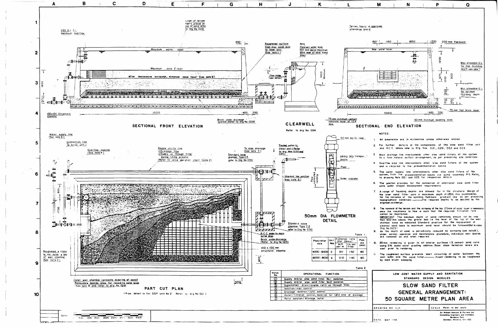
B H M N
8
10
250 D;C CJ_Betlrrouth overflow
Layer of terromfopric placed on1P-P of sand reterTo Drg No 0 2 9F
2002 0 0 ' i Roughened surfacefrom moi sand level10 POM level(See note II )
Te.rrarntoDnc of approvedalternative brand
1501 ! 1150 1850 1200
Cleorweli water level100 mm above Jnojnmurnsand revel~oT slow sondfilter ~~
Mai water level
200 mm free boord
iT8
MOII ollowoble G I
for max foundinodepth see note'7
I Min.W !2T_.
Min. ollowoble G Lfor optimumfourding depth
5000 I40CT >25Ornm f lot bnck Iqyer
SECTIONAL FRONT ELEVATION
>Brick under dra inage 'sys tem .(.Heter To o r q - N o - 0 2 9 *
CLEARWELLRefer to drg No. 034.
75 mm minimum cementconcrete kiver of I-2-4mix.
50 rnm minimum bedding sand
SECTIONAL END ELEVATION
Water supply tine(See note 5 )
nnection lineto filler unit I Treated water to
clear well ( Re forfa drg Nos Q?Oogd035)
To main dra in a qe(See note 3 7) Droinoqe flow
)Supply up through f i l l e r
during fi l l ing process
{Refer to valve ope-fotio'. chart tpple 2 )
Stondgrd valvechomber TypeCSrefer to Drg No 050
;-(Blonked tee junction ^3. c(see note 6 ) £ ~
Standard voivehomber Type_C 2
mfer to Drg No 0 5 0
R.C.C Mobs to momoutlet aVorBnck under droinoqe(Refer to drq No 029)
100 K 100 mmstructural chamfer
to tne outer js des?j weir chamber(See note II )
5 0 mm dig Gl riser
Heavy duty transpar- *_ plastic
Slider indicator
50mm DIA FLOWMETERDETAIL
Table I .
Populationsize
4000 -6000
6O0O-80OC
UnitNos
2
3
Filtrotion rote(For 24hrs)'m/h
per m
Oil
010
1/s perfilter
152
1-40
Pipedia
(mm)
80
6 0
NOTES;
I. All dimensions ore in millimetres unless otherwise stated
2 For further details of the components of the slow sand filter unitond R C C details refer to Drg Nos 0 2 1 , 0 2 9 , 0 3 2 and 0 3 3
3 Main drainage line interconnects other slow sand filters of the systemto a final natural outfall arrangement, as per prevailing stte conditions-
4 Overflow pipe line interconnects other s!ow sond fi lters of the systemond is recycled to the presedimentotion basins
5- The wafer supply line interconnects other slow sand filters of thesystem, from tne presedimentation basins via pump assembly P-5- Refer,to drawing No's- 021 ond 005 for respective details
6- Th* junction provides for the connection of additional slow sond filterunits under staged development requirements
7 A range of founding depths are allowed for in the structural design ofthe slow sond filter upto a man mum depth of i.25m, this accomodatesfor the variance of the systems hydraulic gradient line os per prevailingtopographical conditions .The required depths to be decided by theengineer-in-charge.
8 The removal of the terram and the scraping of the top 25mm of sand layer >s necessaryonce the resistance to flow is such that the required filtration ratecannot be maintained.IMPORTANT The mint mum depth of sand remaining should not be lessthan 650mm above the gravel bed ie the level of the top of the weirchamber base os indicated Stondord proctice for the replacement ofcleanea sond bock to maximum sand level should be foUowed(Ref to notesDrg No 0 2 9 )
9. As the depth of sand is periodically reduced by scraping (see noteS ),under normal operation ond maintenance procedure, individual weir boardsare removed os and when required
D 20mm rendering is given to all interior surfaces 1-3 cement sand ratiousing 5% pudlo water proofing additive Base slope formation levels arecast prior to rendering
tl The roughened surface prevents short circuiting of woter between thewall sides and the sand f i l ter* Fresh rendering to be roughenedby hard brush sweeping
Table 2
OPERATIONAL FUNCTION
/Inlet weir chomber (prevents scouring of sond)Removable boards qllow for receding sond, level'See note 9 ond refer to drg No 029*
Supply ond/or slow sond tiller Not isolationSupply ond/or slow sond filter No 2 isolation
PART CUT PLAN( Pipe detail is for SS.F unit No 2 Refer i 0 drg No 02l )
Supernatant drain/reverse refill up through filterIsolation/inlet controlDroinoge isolation / refill controlOutlet / filtration control; Isolation for refill and or drainage
Refill isolation / drainage outlet _______
500 1000 1500 2OO0 25OO JCXO S5OO 4000
LOW XOST WATER SUPPLY AND SANITATION
STANDARD DESIGN MODULES
SLOW SAND FILTERGENERAL ARRANGEMENT-
50 SQUARE METRE PLAN AREAD R A W I N G N O C J b S C A L E R i f t r to bar t co le
LidSir Wilh«m K*Krow fc PConsulting Engine*'* »nd Archilt>cu
fktrttorop Park.hjh.ft, Srw OQD

u
IMPORTANTB.S.I377 1975 SAND PARTICLE SIZE DISTRIBUTION CHART
Use sand within thespecification range
With reference to distribution chart• Effective size dio to be in range 0 15 - 0 30mm (10V. ofsample
may be finer)s Uniformity coefficient d*0 £ 3
l i r t t i i f n i m V I V A - "\ t t t W t " ™
GRAVELGRADE( mm 1
0 7
2 0
6 0
1 * 0
1-4
4 0
C O
SCO
OUANTFtLTE
25»1 65
1.60
1.35
S 00
TY( milR SIZE
5 0 *3. 25
3.15
3 OS
C.3S
Brick under drainageSec further detail.
H
IMPORTANT : For rtsanding the new »and is not added totop of sand bed Existing filter containing thenecessary mtcro- organisms for purificationshould be tronsfered above new sand
M N
6 5 0
TrT.vTr- JI
400
Before rtsandino.•after successive
sand at minimum depthings-
After resonding
Biologically active for effective purification 400mm.Lower undisturbed sand-Gravel bedUnderdrainage
RESANDINGNot to scale)
DETAIL
Brickwork with\:A cement sand
Render t2_mm__I 5 cement sand
Flat brick loyer
140
Water appliedby hose
Cement concreteto I 2:4 mix costto formation andtrowel finish .-
Timoer weir board(See detail)
(OOxjOOmrr12 mm dia G Iliftmg handle
SECTIONAL FRONT ELEVATIONstnp rretol - 6 ^ , - T —{_
^
r
,60»25recess
PLAN VIEW
up a-5£_
WEIRBOARD SECTION
Droinoqe tonatural outtollmtnimum 6 inlength
250SAND CLEANINGBAY DETAILScale (t>)
300 250 5 0 0 2 4 0 ccs
\0nlv suppor ting on edgebricks ore mortar bedded(12 4 cement sond) to bose
SAND, GRAVEL(Note Slow sand filter
Internal supportingbricks mortar beddedond mortar jointed
AND UNDERDRAINAGEsection features the 25 m size
External supporting bricKsmortor bedded with oopsin joints for tree flow ofwater
D E T A I L Scale (a)
8
9
10
NOTE'
Brick work for outlet withmortor bed ond verticaljoints
350 i 230 x 75Precast concrete (1=2:4 mm)Blocks placed to gapsshown, over main drain
Puddled flange water bar200 mm dia.
NOTES:
I. All dimensions are
2.
in millimetres unless otherwise stated
5 mm QQP is given astolerance betweenrebate ond weir boards
3 mm flat metol edgingto bogrd screwed intoploce
10 mm dio Gl handlebolted through board
Filtered water to cleorwell INLET WEIR CHAMBER DETAILScab c )
12 mm render withroughened surfaceto prevent shortcircuiting of filteredwoter
PLANScale (o)
UNDERDRAINAGE OUTLET DETAIL
WEIR BOARDSECTION
(Not to scale)
Commisioning of the filter is achieved by filling water, initially from thebottom up,until the level rises just above the sond thus allowing final inletflow without scour and preventing air entrapment.
3. Maturation period takes 2 ' 3 weeks, before the newly commisioned filterbecomes effective in purifying the water » during which time the filter isoperated at '/4 the design rate ond filtrant run to waste. Filter is placedinto full operation once the schmutzdecke , a reddish brown sticky coating,has formed on the sand surface-
4. Once the required filtration rate con no longer be maintained, due tohigh resistance to flow of the filter medium, cleaning of the sand isnecessary. The frequency of cleaning will vary from 2 0 - 4 0 days, (less witnterrom fabric m ptace- see G.A. detail) depending on quality of raw water
5. Cleaning procedure :•• Drain supernatant to about (00mm below sond level and remove terrom• The top 25 - 0 mm of sand is scraped ond removed, observing all
necessary levels of hygiene and eiposing the sond for the minimumof time. The terram fabric, once cleaned, is ptoced bock the top of the sand
• The filter is refilled with water ( see note 2 )• Filtration ra te , initially at l /4 design rate with filtrant run to
waste, is brought up to full design rote over 12 hours, ond filteredwater placed into supply after 24 hours.
6 The scraped sand should be thoroughly cleaned, (see cleaning baydetail) , and protected ogainst dust and pollution by adequately storing
7. Resondtng (see detoil) is required once the sond level reaches aminimum depth of 6 5 0 mm , after successive scrapings. After re sandingthe filter will take o minimum of one week to reach full maturation
SECTION A-AScale lo)
Outlet
OUTLET DETAIL
lOmm Gap
LOW COST WATER SUPPLY AND SANITATION
STANDARD DESIGN MODULES
SLOW SAND FILTER
GENERAL DETAILS AND INFORMATION
D R A W I N G N O . 0 2 9 S C A L E . R e t * ' to bar t c a l t i (a),(b).
Scale ( b ) >
400 600 1200 1600 2000 2 0 0 4000 6O0 Bno 1000 1200 1400 D A T E : MAYBurd*iop Pa
Asctwitctt.

B H M N
8
80 RI6I0I) 150140 EF)
40RI6(03) 150 U Bors
34 RI6(O7)I75 (I7EF)
17 RI6(O8)I75 U Bars
34 R12 (09) 150 U Bars
6BRI6I06) 150 (34EF)
6BRI6(04)l50(34EF)
34RI6I05) 150
J
40 RI6 (03)150 U Bors
40 RI6(O2)I5O U Bars
Inltt chamber above ^(See detail A) ^-——
80 RI6(0l)15O (40EF)
.40 R16102)L50-U. Sors
—'
T T
- -
•
1
T
—•—
JL
4 RI2 (10)150
I 7 R 12(11) 150
! 4 RI2(IO)I5O
DETAIL A - INLET CHAMBER(Scale b)
BASE PLAN (Scale a)
rnJO
4 RI2UDI50
ELEVATION WALL A (Scale b)(WALL B SIMILAR BUT HANDED)
17 R16 (08) 175 U Bors
SECTION C - C(Scale b)
4 R 16(06) 150 12EF)
NOTES:
I This drawing to be read in conjucfion with drawing numbers 027, 029 8>O3Iand the retevent btnding schedules.
2 . Concrete mix to be 1*1 2:3 cement/sand/course oggregate by volume-
3 . Minimum concrete strength to be 25 N/mm1 (3625 Ib/in1).
4 . Maximum aggregate size to be 20mm (3/4 in).
5 . Minimum cover to all reinforcement to be 50mm 12 in).
6 . Laps to reinforcement to be 40 times the diameter of the smaller bar.
7 . Reinforcement to be grade 250 N/mm' ( 3 6 2 5 0 l b / i n ' ) plain bars.
8 . Reinforcement nomenclature:
3 - R 16 - 3 9 - 2 0 0 - T
L Position of bar (see note9)L Bar centres (mm)I Bar mark (sec Bending Schedules)
I Diameter of bar in millimetresType of steel (R = mild steel)
— Number of bars
9 - Abbreviations referring to positions of reinforcement
EF = Each faceNF = Near faceFF = Far face
B = BottomT = Top
10. Where reinforcement fouls pipes or openings, bars ore either to be bentaside or are to be cut to suit and spliced with similar sized bars.
II Safe soil bearing pressure should not be less than 75 kN/m ( 0 . 7 ton/ft }.
12. The contractor to provide to the Engineer for testing,3 Na concrete test cubes for each concrete pour
13. This drawing is schematic only. Do not scale
10
TYPICAL WALL ELEVATION (Scale a)(4 No. THUS)
LOW COST WATER SUPPLY AND SANITATION
STANDARD DESIGN MODULES
25 SQUARE METRE SLOW SAND FILTER
REINFORCEMENT DETAILS (SHEET I OF 2)
P H A W I N G NO 0 3 0 S C A L i R«f«r t* bar tcaltt
I000 2000 5000 4000 1000 200 -000 1000 1400 WOO OAT! MAT ! » • •WK»O» Part. MMMurr MM tOO

1
—
2
3
—
4
5
—
6
—
7
8
Q
10
A """ i B i c
06T 07
09 '
0 4 T
0 5 T
06L ff
07Ol
I .Ol
I—Ol
06
06
oeT
071
0606
mrr.
Scon t^HlmmPm^m^^lmJmUmm^
1
•
)07 JO6
: x°9
T04
02
106107\ ^
, \ .
02
—
•
*
' <
• ;
0 6
06
Toe
1 H2Z
|O6
0 6
07
D ,
-H —<05 04
04
OB
0 8
E |
SECTION
SECTION
F i
A- A
B- B
G H
06T 0 7
0 9
0 4 "
02).—
0610 7
* /
04 *05 ^02
0 6ru 06
oeT
06 070 7 i
06
oe 07
J
V
07 T°6
I 0 9
! T04
Tos
2,' 10607
01
; )
01
a1
•1
•
06
06
Toe
I07
0606
0 6
1 K ! . L M N P Q
N O T E S
1 For position of sections see drawing number 030.
2 Reinforcement nomenclature:
0 5 Bar mork 05
I Position of end of bar
3 For bar positions, spacings, and diameters referto plans and elevations on drawing number 030
4 For bar shapes and lengths refer to releventbending schedules.
3 The notes on drawing number 030 also apply-
6 This drawing is schemotK only. Do not scale.
LOW COST WATER SUPPLY AND SANITATION
STANDARD DESIGN MODULES
25 SQUARE METRE SLOW SAND FILTER
REINFORCEMENT DETAILS (SHEET 2 OF 2 )
D K A W I N G N 0 03I jSCALE Raftr 10 bar icon
l» Wtan HMcroo A h u m IM
OAT!: MAY I M S S««««o". Win**™. «N4 000

8
9
10
B
WALL C2 « 2 RI6 (01) In sides
8 2 RI6 (O0I5O (4IEF)
41 RI6 (04)150 U Bars 41 R16 (04)150 U Bars
75 RI6 (05) 150 U Bors
75 RI61031I50 B
75 R20(02)I50 T
inlet chomber above J(See detail A; /
2 * 2 RI6 (03) In sides 2
75 RI6 (C5) 150 U Bars
/
2T T T
-^
1
A\
! 1 ,
i
T
j
- * -
_-,-1
Ii i
L
WALL A
BASE PLAN (Scole o)
20 RI6II3) 150 NF
40 RI6(I3) 150 (20EF) 40 RI6(M) 150 (20EF)
40 RI6 (13) 150 (20EF)
20 RI6(I3) 150 NF
67 RIO (14) 150 U Bars
4 + 4 RI6(IO) 4EF
134 RI6 109) 150 67 EF
67 RI6 (08)150 FF
67 RI6 (07) 150 NF
67 RI6 (06)150 Bent Ban
2EF
! T T
!. u
[':I
H
T
.
±
T T
±±-
!
1
—t
,|2EF
i
•
ELEVATION WALL A (Scole a)
(WALL C SIMILAR)
H K
4 RI2 (17) 150 (o-d)
5 RI2 (16) 150
9 RI2II5) 150
5 RI21I6) 150 I
1
T
I
X
ELEVATION WALL E (Scole b)(WALL F SIMILAR BUT HANDED)
PLAN DETAIL A
INLET CHAMBER (Scale b)
17a
17b
I7e
I7d
"7117 aIl7bil7cIi7d
15
SECTION D-D (Scale b)
40 RI6(12) 150 (20EF)
34 RIO 114) 150 U Bars
i 68 RI6(09) 150 (34EF)
f~..4 RI6 106)150 FF
J 3 4 RI6107) 150 NF
1 34 RI6106) 150 Bent Bars
ELEVATION WALL B (Scale a)
(WALL D SIMILAR)
M N
NOTES
1 This drawing to be read in conjuction with drawing numbers 0 2 8 , 0 2 9 , 0 3 3and the relevent bending schedules
2 Concrete mix to be l l ' ^ ^ cement/sand/course aggregate by volume
3 Minimum concrete strength to be 25N/mrr? 13625 Ib/in )
4 Maximum aggregate size to De 20mm (3^< in)
5 . Minimum cover to all reinforcement to be 50mm (2 in).
6 . Lops To reinforcement to be 40 times the diameter of the smaller bar
7 Reinforcement . to be grade 2 5 0 N/mm' ( 3 6 2 5 0 Ib / in 2 ) plain bars.
8 Reinforcement nomenclature
3 - R 1 6 - 3 9 - 2 0 0 - T
I— Position of bar (see note 9 )'— Bar centres (mm)
_ Bar mark (see Bending Schedules), 1 Diameter of bar in millimetres
I 1— Type of steel (R*mild steel)1 Number of bars
9 . Abbreviations referring to positions of reinforcement
EF =NF =FF =
Each faceNear faceFar face
BT
= Bottom= Top
10 Where reinforcement fouls pipes or openings, bars ore ettner to be bentaside or arc to foe cut to suit and spliced with similar sized bars
11 - Safe soil btanng pressure should not be less than 715 kN/m' (0 7 ton/ft ) .
12. This drawing is schematic only. Do not scale
13 The contractor to provide to the Engineer for testing,3 No. concrete tesf cubes for each concrete pour.
LOW COST WATER SUPPLY AND SANITATION
STANOA RD DESIGN MOOULES
50 SQUARE METRE SLOW SAND FILTER
REINFORCEMENT DETAILS (SHEET I OF 2 )
0 K A W I N G NO 032 1 Rt.tr to bar tc«ltt
2000 3000 4000 SOOO
S» WilMin MMcrw • h m n Ltd
2 0 0 D * T I JUNE 1988 SII Ha'i. (WUMra. SM4 000

B
8
10
•V.
03 07 08 06
04
SECTION A - A
09
I3T
I3T
"1 09
10 10
10 10 09
SECTION C - C
H
0 9
66 "oB *07
•5503
0 9
Tl3
[i i09 i-09
13
0 9
isT
12III
X 0909
: •
, t
09
TisT.3
09 i-
10 10
09 10 10
15*15
M N
Q i ;09T
14.
08 T
0 9 iI2J
y02
To9
T07
To 6
, I 0303
03 03
I— I 1—• —<06 08 07 01
05
SECTION B - B
NOTES
1 For position of sections set drawna. numb*r 032.
2 R«inforc*mtnt nomanclatHr* •
05 Bar mark 0 5
~T Position of end of bor
3 For bor positions, spacing*, and diameters referto plans and elevations on drawing number 032.
4 For bar shapes and lengths refer to releventbending schedules.
5 The notes on drowing number 032 also apply.
6 This drawing is schematic only. Do not scolt.
LOW COST WATER SUPPLY ANO SANITATION
STANDARD DESIGN MODULES
50 SQUARE METRE SLOW SAND FILTER
REINFORCEMENT DETAILS (SHEET 2 OF 2 )
DRAWING NO 033 SCALE R«l»r to bor • » ! •
0 200 600 1000 1400 1600O A T I : JUNE ! » • •
Str m u m I l i k w * twnmn u\ Iflgnnn ftntf AiKiiww
an. WiMhife. KM OOO

D H K M N
Puddled flonqc jw__vent 80 mm dip- /Gl threaded pipe
Q mm dto MS roosot 200 cTs
lOmrn diG MS rod150 mm long oncnoroqe
6 0 05 No 50 mm hinges per door width
iveted to flat metal frame
600manhole
cover secu7ecT~*in place by haspand padlock
Gl sheet metal 22J3WG gauge
riveted to a flat metal frame
38 mm x 4 mm10 mm did MSrod at 150 ccs
x — I m SO \ / I in 80
; 150mm long onchoroqe
50 mm bedding sand
50 mm Bedding sand Stonaard footvolvcwith strainer
refer to Drq No 049
HINGED DOOR DETAIL
SEC TIONAL FRONT ELEVATIONScale ( a )
^ Ftat prick layer
| G l clamp 25mm X6mm
with 100mm onchorage
BOOSTER PUMP BAYScale (b)
PART CUT SECTIONAL
END ELEVATIONScale (a )
~T
Root slab slope
r v soBase slob slopetowards dram outletI in 50 "~
2500
8
20 mm Bender Root sk» sbpesee note t3 I in 8 0
Gl sheet metal 22 BWGgouoe riveted fe Trarhe'DroinoQ, to nulloh
or natural outfall
Access rungs 12 mmGl rods ptocvd at
Gl sheet metal 2 2 BWG
gouge riveted to frome
^ 0 x 4 0 1 6 onqle iron frame
\ 2 No 6 4 mm twqes;' riveted in place
1 12 BWG gauge collar) 6 0 0 « 6 0 0 internal
-"* dimension
Live capocrty
Gal
2500
5000
7500
topoo
l^000
20,000
ml
1 1 4
226
341
4 5 5
6 6 3
910
DimensionLength
L
3650
3650
5400
5100
7650
10200
Widthw
1800
3650
3650
5100
5100
5100
DepthD
2200
2200
2200
2200
2200
2200
ThicknessWall
t,
2 0 0
2 0 0
2 0 0
250
250
250
Rooftj
200
200
2 0 0
250
250
250
Bosetj
2 0 0
200
2 0 0
250
250
3 0 0
HeelLength
(mm) t«No 12)
Detail
250
350
300
4 0 0
4 0 0
\._2mm X 25mm strip metoi anchor age fillet
welded to collar on four sides
MANHOLE COLLAR/ HINGE DETAILScale ( c j
millimeter* unless otherwise stated
(1) See note 2
(2) No heel is required for this size clearwell.
BOOSTER PUMP BAY
NOTES
1 . Al dimenswni arc given
2 The dimensions quoted ore to t » surfaces of the R C C , the live capacity is calculated
aitowng for the Wtowtig voOnemc reductions
I) 2 0 m m the* water prooftnq plaster rendering
ii) I in 150 base sbpe
m) 150 mm deptn freeboard
rv) 2 5 0 mm depth dead storage
3 For further details of booster pump assembly and otter native pump assembly
layouts, refer to drg No OO6 Level to be s t t according, to calculated suction head
and NPSH for the booster pump
4 - For full RCC detaits, for the range of cMorwetl sizes, refer to arq Not
0 3 5 - 0 4 6 and relevon* bending schedules5 2 0 mm miclc internal fender to waits and base using, I 3 cement sond rote with 5 % woter
proofing pud to odditrve.
102 5 0 mm ccs
PART CUT PLAN VIEWSea. ( a )
LOW COST VKTER SUPPLY AND SANITATION
STANDARD DESIGN MODULES
CLEARWELL /BOOSTER PUMP BAY
GENERAL ARRANGEMENT
D R A W I N G NO 0 3 4
Scale a)0 400 BOO 1200 WOO 1000
Scole c)0 D 20 B « W U 70 » » «O
Scale » )
SwiMaA W.HM'—# $*** 000

u b / H M N
WALL C
18 RI2 (01) 200 (9 EF)
9RI2I02) 200 U Bors i 2 EF
WALL A
BASE SLAB
3 RI2 (16) 200 U Bors
2 x 3 RI2 (IS! 200 U Bors
3 RI2 (14) 200 Links
6 RI2 (17)200 (3EF)
9 RI2 (16)200 U Bars
12 RI2(I8)2OO (6EF)
NOTES
1 This drawing to be read in coniuction with orawing Nos. 034 8 036and the relevent bending schedules
2 Concrete mix to bt l:t"*'-3 ctment/sond/course aggregate by volume.
3 Minimum concrete strength to be 25 N/mm'(3625 Ib/in2 )
4 Maximum aggregate size to be 20mm (V« in ).
5 Minimum cover to all reinforcement to be 50mm (2 in).
6 . Lops to reinforcement to be 40 times the diameter of the smaller bar.
7 Reinforcement to be grade 2 5 0 N/mm ( 3 6 2 5 0 Ib/in ) plain bars
8 . Reinforcement nomenclature :
3 - R 16 - 39 - 2 0 0 - T
LL L Position of t
Bor centres (mnbar (see note 9)
m)1— Bar mark (see Bending Schedules)
Diameter of bar in millimetresi— Type of steel (R = mild steel)
Number of bars
9 . Abbreviations referring to position of reinforcement:
EF = Each faceNF = Near faceFF = Far face
B = BottomT = Top
10. Where reinforcement fouls pipes or openings, bars are either to be bentaside or are to be cut to suit and spliced with similar sized bars.
II Safe soil bearing pressure should not be less than 5 0 k N / m ( 0 . 4 5 t o n / f t 2 ) .
12. This drawing is schematic only. Do not scale
13. The contractor to provide to the Engineer for testing, 3 No concretetest cubes for each concrete pour
ROOF SLAB
22 RI2 (11)200 (II EF)
RI2 (10) 200 U Bors
4 RI2 104) 2 E F
RI2 (10) 200 U Bars RI2 (12) 200 U Bars
11 RI2 (12) 2 0 0 U Bars
4 RI2 (05) 2EF
8
36
8RI2 (06)
RI2 (07)
2 0 0
200(18Bent
EF)bars
1
f~
|(
J2EF
It "u-1L
T
j
1
T
i -i
T ~|i
1 2EF! I ,
I . . 1j 1
i _j
18
2x
~°)RI2(08)2O0 U Bars
4 RI2 (09) 4 EF9 RI2 (08) 200 U Bors
8 RI2106) 200 ( 9 EF)
9 RI2(07) 200 Bent bars
i
i
,
1,,
>i •
-
11I1
i
• • I 1
i
i
10
WALL A(WALL C SIMILAR)
WALL B(WALL D SIMILAR)
LOW COST WATER SUPPLY AND SANITATION
STANDARD DESIGN MODULES
11.4 CUBIC METRE (2500 GALLON)CLEAR WELL
REINFORCEMENT DETAILS (SHEET I OF 2)D R A W I N G NO 0 3 5 SCALE R*(«r (o M r iCOtl
1000 2OOO 3000
S« Militam MaicroMr 4 Cmnnmtt ltd
SwwtOon Mifttftin 5N4 OOD

B H K M N
6
13 13
04 04 18 B 17 17 17 18 IB 04 04
04 04.
07F°6'
oej_07
04 04'^pV04 I
I1118 17 ,7 17 18
13 ,3
Toe
03 03J _ 0 8 ~~ 08
, IIIV \ 01
_J_
_•__• y-t . • 04 04
04 04
II
Is VI 08
07
04 01J04
01 04
0 6 03 0 3 06
06~ ~06
0 ' ~07~
I 4
04 04 18 i 18
0 4 04J
r0 6 1
07 1
08|^
0704 041
04[
18 18
706
18
04 01
0 6
: 108 -22 53_ o ein J-
18 04 04
04 04II
I 07
lO8
07|04 04I 04
06 03 03 06
06 06
07~ 07
05 05
05 05
12
07
08
071
12
05 0505
17 16
l~06
12
^ '—
05 03
01 06
06~"
0 7
13 05 05
c:12
17 16
: : : : ~ . :
16
1312
17
0 6
2O3 I
03.
, .05 05
12
1°I'2 07105 05J05
06 0
06
07
SECTION A-A SECTION B-B SECTION C - C
8
9
10
09 09 08
090908
080 909
,08
J_,2
0808
09 09 08
10
SECTION D-D
10 I
08 09 09
O S ,
10
,2T
,0
O8,06
10909
08
T.2
I'2
0 8
0 8 09 09
~io~ II
NOTES
1. For position of Mctnns aae drawnq numbar 035
2. Reinf orc*m«nt nom«iclotur« •
0 5 i i B» mork 05
""H , Position of and of bor
3. For bar position spocinos ond diameters refer to drawing No 035
4 For shapes and lengths refer to rele»ef* bending schedules
5 . The notes on drawing number 035 also apply
6 The drowng is schematic onry. Do not scale
LOW COST WATER SUPPLY AND SANITATION
STANDARD DESIGN MODULES
11.4 CUBIC METRE ( 2 5 0 0 GALLON)CLEAR WELL
REINFORCEMENT DETAILS (SHEET 2 OF 2 )
D R A W I N G NO 0 S 6
0 ZOO 600 1000 1400 1800
HMcrow * Pvnnart Liaitfinnra MM Arcnucu
DATl JULY 198 8 I M M SN4 000

B H M N
WALL C
8
44 RI2 (00 200 ( 22 EP ) R I 2 U 4 ) 2 0 0 ( 4 E F )
2 2 R I 2 (03 ) 200 U Bors 2 2 RI2 ( 0 3 ) 2 0 0 U Bars 4 RI2 (13) 2 0 0 U Bon
<= . J B
< ^
44 RI2 (01 ) 2 0 0 1 2 2 EF )
2 2 RI2 ( 0 2 ) 20C U Bors
T -'
_!_ _L
_
-p
i • » • • i
j
_L
1
14 R12 113) 2 0 0 U Bora
28 R 12 I I I ) 2 0 0 ( 14 EF)
18 RI2 (13) 2 0 0 U Bors
WALL A
BASE PLAN
2 6 R 1 2 ( 0 7 ) 2 0 0 ( I 3 E F )
II RI2 (08) 2 0 0 U Bore
3 RI2 (12 ) 2 0 0 U Bars
2 R 12 (15) 1EF Trimmer Bors
3 R I2 (12) 2 0 0 U Bora
1
; : '
T i t ) "• ^ i i •
hA
/ )
bs('
7
L
S i 1
1
1
T "7
» 1 III
•-' 1
j -
18 RI2 l I C ! 2 0 0 U Bors
30 R I2 ( I I ) 2 0 O U 5 E F )
18 RI2 (10) 2 0 0 U Bars
NOTES
ROOF PLAN
26 R 12 (07) 2OO(I3EF)
R 12 ( 08) 200 U Bora
2EF
I Trvs drawing to De read in conduction with arawmg numbers034 S 038 and the reievent bending schedules
2 Concrete mix to be M!^. 3 cement/sand /course aggregate by volume
3 Mnmum concrete strength to be 25 NAnm ( 3 6 2 5 ib / in ) at 2 8 days
4 Maximum aggregate size to be 20mm { \ in )
5 Minimum cover to all reinforcement to be 50mm l2m)
6 Loos to rwnfcrcement to be 4 0 times the diameter of the smaller bar2 2
7 Reinforcement to be grade 250 N/mm ( 3 6 2 5 0 to/m) plom bars
8 Reinforcement nomenclature
3- R 16- 39-200- T
L_ Position of bar ( see note 9 )_ Bar centrms (mm)
Bar mark ( M « Bending Schedules)Diameter of bar m mMlmetret
Type of steel( R = mid steel)Number of barsI—Typ
9 Abbreviations referring to positions of reinforcement
EF •NF =FF =
Each faceNear faceFar foce
BT
: Bottom= Top
10 Where reinforcement fouls pipes or openings, bors an eithar to be bentOSK)« or ore to be cut to surt and spliced with svntcr sized bors
11 The contractor to provide to the Engineer for testing, 3 No concretetest cubes for eoc h concrete pour
12 Safe sotobeonng pressure tfiould not be less thon 5 0 kNAn 0 45 ton / f t )
13 This drawing is schematic only Do not seal*
10
ELEVATION WALL A
(WALL C SIMILAR)
ELEVATION WALL B
(WALL D SIMILAR)
LOW COST WATER SUPPLY ANO SANITATION
STANDARD DESIGN MODULES
22.8 CUBIC METRE (5000 GALLON)CLEAR WELL
REINFORCEMENT DETAIL (SHEET I OF 2)DRAWING NO 0 3 7 S C A t i »««jr to bor i c o n
IOOO 2000 3000OAT I JUNE I986
SM Wtltam HMerow * Pannati Ltdrnw^wina. twojn—n end Af«*MMcu
WiHtfur« SN4 ODD

8
10
B
II 10
07 07 II
osT0 4 T
0 ,
0 6 J -
II 10
: Tos
i 02
r ^ r
0: 02 04 05
^5~
09 09 06
07 08
a ii
14 14 14 14 II II 07 07
II 14 14 14 14
02
4; TOS
ijo,
l~7 -L°6
Ol
T04
D
05 04 02 Ol
~oi
SECTION A-A
06
06
oeT
07J^ 06
09 09
i a
ia
i a
>a
' \• i
>>
06
06
Toe
,07 08
06 JO7
06
06
oeT
08 07 ,
°7io6
i a
' a
•«
1 i
• •
-
06
06
i
T
06 J
09 0
0 8
06 09 09
07
SECTION C-C
H M N
07 07
13 14
II 07 07
04
05T
T 00 6 X "H
07 i22
07j o e 0 6
^ 0
05T |
fTos
|OI T ° 4
— j_0607
LTD'Ol
01 03 OA 05 05 04 03 01
05
SECTION B-B
NOTES
1 For position of sections see diuwiig number 037
2 Reinforcement nomenclature
05 i i Bar mark 05
• I —1 Position of end of bar
3 For bar position spocmgs and diameters refer to drawing No 037
4 For shapes and lengths refer to relevent bendng schedules
5 The notes on droaang number 0 3 7 also apply
6 The drawing a schematic only Do not scale
LOW COST WATER SUPPLY AND SANITATION
STANDARD DESIGN MODULES
22.8 CUBIC METRE ( 5 0 0 0 GALLON )CLEAR WELL
REINFORCEMENT DETAILS (SHEET 2 OF 2 )
D R A W I N G NO 0 3 8 SCALE R*tf«r to bar tcoi*
0 200 600 1000 l«00 1800
Sn WiHiOT HaicrOMr I i P»nn«r« ltd
Co*wuwwt inginsarr* MM ArcMIMCU
DAT I JUNE 19*6

8
10
B H K M N
W A L L C
6 4 R I 2 ( 0 3 ) I 5 0 ( 3 2 E F )
3 2 R I 2 1 0 4 ) I 5 0 U Bors
4 2 R I 2 ( 0 2 ) I 5 0 U Bors
3 2 R I 2 ( 0 4 ) I 5 0 U Bors
8 4 R I 2 ( O l ) I S O ( 4 2 EF
4 2 R I 2 ( 0 2 ) 1 5 0 U Bors
3 4 R I 2 ( 1 0 ) I 5 0 ( I 7 E F )
I 5 R I 2 ( 1 2 ) 1 5 0 U Bors
36RI2 (08) 150 U Bors
4 R 12 (13) 2 EF
72 RI2 ( 0 6 ) ISO ( 36 EF)
36 RI2 I 0 5 ) 150
WALL A
BASE SLAB
I5RI2 U 2 ) I 5 0 UBars
i T
u 1 I
H
WALL A ELEVATION
(WALL C SIMILAR)
4 0 R I 2 ( J 5 ) I S O J I O E F +10 EF
4 R I 2 H4) I 5 0 U Bors
I C ) > l 0 R I 2 t ! 4 ) 150 U Bors
8 R I 2 U 6 ) I 5 0 ( 4 E F J
2 4 R I 2 I I 4 ) I 5 C U Bors
3 6 R I 2 ( I 7 ) 150 U Bors
4R|2( I9 ) 150 U Bors
64RI2 (18) 150 (32EF
2 R I 2 ( 2 O ) I E F Trimmer Bors
4RJ2JJ9! l50_U_Bqrs.
36R 12(17) 150 U Bars
I5RI2 (12) 150 UBars
ROOF SLAB
3 4 R I 2 ( I I ) 150 ( I7EF)
I 5 R I 2 ( 1 2 ) 150 U B o r s
4 RI2 (13) EF
24 RI2 (09) ISO UBars
_4S_S12_1O7) ISO (24EF)
24RI2 ( 0 5 ) 150
T
NOTES
: Tnis a raw ing to De read in comuction witr arawrg numoers 034 9 04Cana fne reievent benaing scnedutei
2 Concrete mix to be M V 3 cement/sona/course aggregate oy volume
3 Mintnum concrete strength to be 25 NAnm (3625 it - n ) at 28 doys
4 Maximum oggreoale size to be 20mm 1 4 in!
5 Minimum cover to oil remfoftament to be 50mm12in)
6 Lops to renfarcement to be 40 times the diameter of me smaller bor2 2
7 Reinforcement to be grade 250N /mm ( 3 6 2 5 0 Ib/in ) piam bors
8 Reinforcement nomenclature
3 - R 16 - 3 9 - 2 0 0 - T
j i L_ Powtwo of bar K see note 9 )' \ j Bar centres (mm)
I Bar mork ( see Bending Schedules )I i ; Diameter at bar in millimetresI L_ Type of steel ( R = mild steel)1 Number of bars
9 Abbreviations referring to positions of reinforcement
EF = Each faceNF = Near faceFF = Far face
B s B oftonT = Top
=4k-J u10. Where reinforcement fouls pipes or openings, bars are either to be bent
a s o * or ore to be cut to surf and sphced with simitar sized bars
II The contractor to provide fo the Engineer fey testing, 3 No concrete
test cuoes for each concrete pour
12 Safe sods bearing pressure should not be less than 5 0 k UM\ Q 4 5 t o n / f t )
13 This drawing is schematic only Do not scale
WALL B ELEVATION
(WALL C SIMILAR)LOW COST WATER SUPPLY AND SANITATION
STANDARD DESIGN MODULES
34. I CUBIC METRE 17500 GALLON )CLEAR WELL
REINFORCEMENT DETAILSCSHEET I OF 2 )D R A W I N G NO 0 3 9 S C * L E R»t»r to bar scoi*
DATE JUNE I S 8 6
clcrowr A P»nt>*<\ mfftg tnQ<n««fs and Aicr"i*ci
roo Partmin.ra SN4 OOP

B H K M N
18 17
10 10
10 10
06»
0 5 'u8j_— ;j
10 i
15
18
106
02 08
U0
01 02 05 06
0 6
15 16 16 IK IK
15 16 16 16 16 15
17 18
15 10 10
15
06 T
08^2
,i 10 10
TC6
T«1_ •
(10
0605
06 05 02 01
06
03j
16 14
18
J_09
03 04 05 07
14 16
18 II II
091,01 ' 05
7 I050:
D
07 05 04 03
SECTION A-A SECTION B-B
8
10
I2 T
13
OS
08 1"
13 13 08
7T
SECTION C-C
II I 09-1- 08
T1S
i 13 13
08 13 13
12 10
NOTES
1 For position of wctions Me drawing number 0 3 9
2 Renforcement nomenclature
05 < 1 Bar mark 0 5
* H | Ftosition of end of bar
3 For bar position spoangs and diameters refer to drawing No 039
4 For shapes and lengths refer to relevent bending scnediies
5 The notes on drawing number 039 also op ply
6 The drawing is schematic only Dc not scale
LOW COST WATER SUPPLY AND SANITATION
STANDARD DESIGN MODULES
34.1 CUBIC METRE ( 7 5 0 0 GALLON )
CLEAR WELLREINFORCEMENT DETAIL (SHEET 2OF 2 )D R A W I N G NO 0 4 0 SCALE FUt*r to bar ica i *
O A T I JULY 19 8 8
Hctcrow «k P»nrt«ri l td
f n*tn*>*>rs «nd Arch>t*cn
W<*»h<rt. SN4 OOP

B H K
8
10
WALLC
64 R 12 (Ol) 150 (42 EF )
42 R 12 (03! 150 U Bon
8 RI2 (14) 150 WEF )
4R 12 (13) 150 UBors
42 RI2 (03) 150 U Bors 15 4-15 RI2(I3) 150 UBors
42 RI2 (02) ISO UBors
m 4 B
P L
84RI2(OI)I5O (42EF)
42RI2(02)IS0 U Bars
i
1 .
i .
X X
1 1
i X
X
• ,
JL
!
i
ji
WALL A
BASE PLAN
34 R 12 (06)150 (I7EF)
15 RI2 (OB) 150 U Bort
4 + 4 RI2 (09)4EF
r34 R 12 (07) I50JJ Bors __
66 RI2 104M30 (34EF)
34RI2 (O5)I5Q_Btnt Bort
|2EF
•It-
X X
2EFI
4—d
ELEVATION WALL A
WALL C SIMILAR
ROOF PLAN
34 RI2 (06)150 (I 7EF.L
15 R 12 (08) 150 U Bort
SO RI2 (10) 150 (30 EF)
34 RI2 (13) ISO UBors
34 R 12 (II) 150 UBors
4 R 12 (12) 150 U Bors
11
!2 RI2 (15) IEF Trimmer Bors j
4 RI2 150 UBars
6ORI2(IO)I5O (30 EF)
34R 12 (M) ISO UBars
>
>
T
in
Vs
\
/
\
/
n
1
T
1
r
i
1U_Uikf)
i
T
LJin
i
i
!1I1
i J
15 RI2 (08)150 U Bars
34 R12 (07) ISO U Bora
68RI2 (04) ISO (34EF)
34 RI2 (05)150 1Bent Bors I
riiii
i -i
i.i 1
11
i_
T
. i i 1
-4—i—4-1
|1___J
ELEVATION WALL B
WALL D SIMILAR
M N
NOTES:
1 This drawing to be reod in conjuction with drawing numbers 034 S 042
and iht retevent bending schedules.
2. Concrete mix to be I I1/* 3 cement / sand / course aggregateby volume .
3 Minimum concrete strength to be 25 N/mm (3625 Ib/in ) at 28 days
4. Moximum aggregate size to be 20mm. ( V * in;
5. Minimum cover 1o all reinforcement to be 50 mm. ( 2 m )
6. Laps to reinforcement to be 40 times the diameter of the smallerbar.
7 Reinforcement to be grod* 250 N/mitf ( 3 6 2 5 0 Ib/in2) mild steelplain bars.
6. Reinforcement nomenclature
3 - R 16 - 39-200-T
I Position of bor (See note 9 )
I Bor centres (mm;Bar mark ( See bending schedules )
Diameter of bar in millimetresType of steel ( R-mild steel )
I— Number of bors.
9 Abbreviations referring to position of reinforcement
EF ' Each foce B = Bottom
NF » Near foce T = Top
FF = Far foce
10. Where reinforcement fouls pipes or openings, bars are either tobent oside or to be cut to suit and spliced with similar sidedbars.
II The contractor to provide to the Engineer for testing 3 noconcrete test cubes for each concrete pour
12. Sate toil bearing pressure should not be less thon 50 KN/rn*
(CO-45 ton/ f t 1 )
13- This drowing is schemetic only Do not scale
L
LOW COST WATER SUPPLY AND SANITATION
STANDARD DESIGN MODULES
4 5 5 CUBIC METRE (10,000 GALLONS)CLEAR WELL
REINFORCEMENT DETAILS SHEET I of 2S C A L E R t d r i « B a r S e a l *
Si' W'tn**** HMC'CM* k PannonCen*uR«nt
OAT I JUNC !«•«
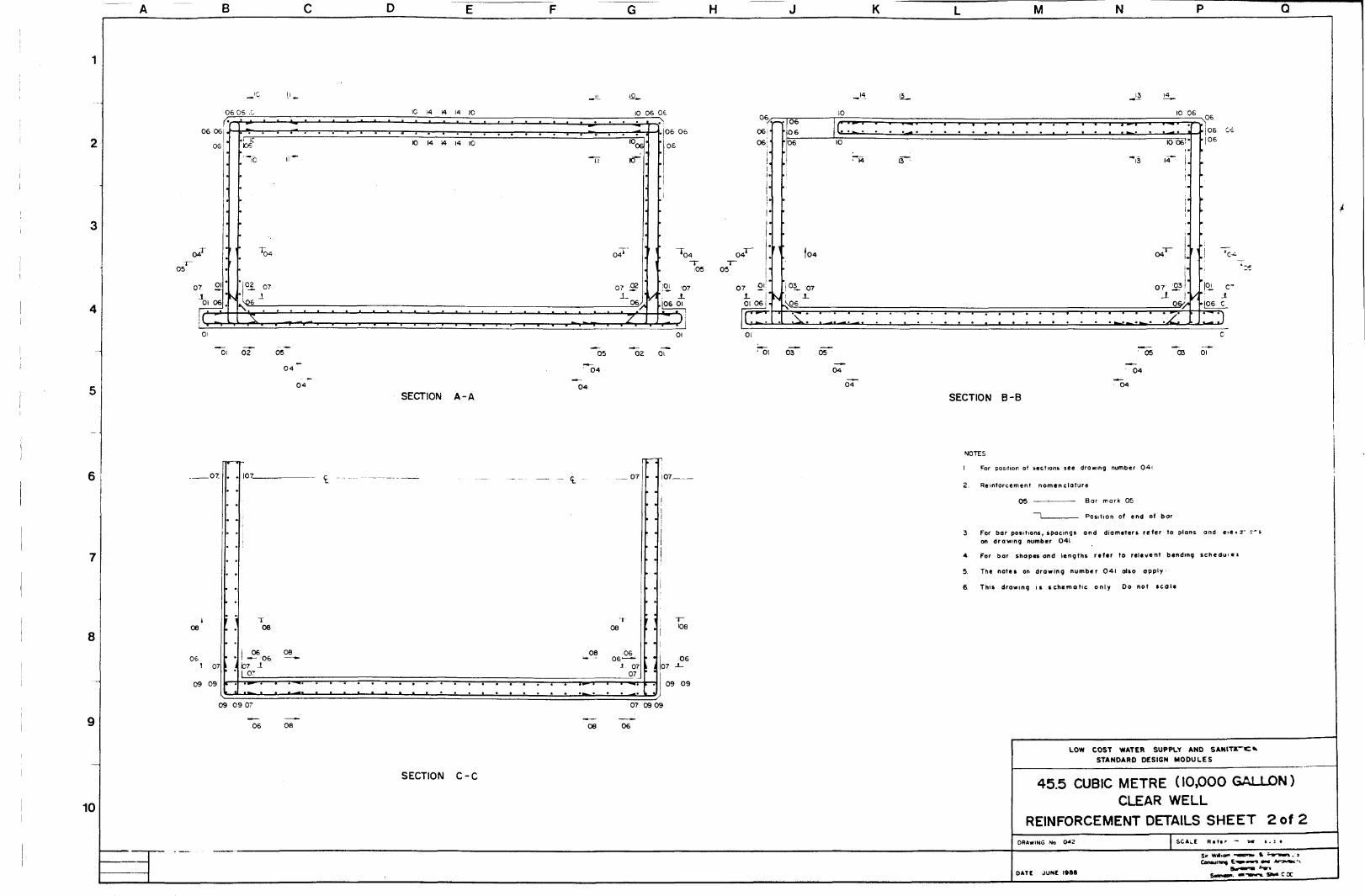
B H M N
06 06
06
05
07 21
01 06
•nr106
T 0 4
02 o
>06
01 02 05
10 14 14 14 10
10 14 14 14 10
SECTION A-A
10 06 06
loos!
KT
O?"
07 S?i_
06,
.J06 06
06
0606i'
'04 04"T 1-
05 05
i L '07X
106 01
05 02 Oi
*04
04
07 £<!
01 06
06060 6
0 4
033- 07
\ 0 6
10
01
'01 03 05
04
SECTION B-B
10 06
10 06
14*"
04
07 IS?
.06
06| 06
•c-
0 6
05 03 01
04
8
10
_07_
08
1 071
09 09
iO7_
08
06 08— 06 —•
i b7 .107
09 09 07
06 08
• • * '
SECTION C-C
07
08
08 06- - 0 6 ^ - ^
-1 0707
107
108
06
09 09
07 09 09
08 06
NOTES
1 For position of sections see drowing number 041
2. Reinforcement nomenclature
05 Bar mark 05
I Position of end of bar
3 For bar positions, spacings ond diometers refer to plans ond eie*?~ '' son drawing number 041.
4 For bar shapes and lengths refer to relevent bending schedu>ei
5 The notes on drowing number 041 also apply
6 This drawing is schematic only Do not scale
LOW COST WATER SUPPLY ANDSTANDARD DESIGN MODULES
45.5 CUBIC METRE (10,000 GALLON)CLEAR WELL
REINFORCEMENT DETAILS SHEET 2 of 2DRAWING No 0 4 2 SCALE Ktimr - *« i . : •
Sir w#ia" i*i"Conultme ! • » •
DATE JUNE ISSS

B H K M N Q
WALL C
84RJ2 (03) 150 " > 2 T . 4 2 B
4 2 R I 2 J 0 4 ' I 5 0 U Bars 4 2 RI2 ( 0 4 ) 150 u Bars
5BRIK (02 I 5_Q._t!-JifllS i_
" rA ^ B
116 R I 6 I 0 I ) 1 5 0 ( 5 8 T . 5 8 S
5 8 R I 6 I O 2 : 1 5 0 U_Bgrs_
WALL A
BASE PLAN
34RI2 (I2)I5O(I7EF)
15 RI2(I3)I5OU Bors
52 RI6D8) I5Q U Bors
, I 5 R I 2 ( 1 3 ! 1 5 0 U Bors
4 R IS I Id) ? E F
8
104 RI6(O5)I5O (52 EF) ;
52 RI2(06) 150 Bent bars
I0RI2 (19) 150 (5EF)
5 R 12 (17) 150 U Bars
15+ IS R 12 (17) 150 U Bars
35 RI2 (17) 150 U Bars
30 .30 RI2 (16)150 II5EF. ISEFS
ROOF PLAN
3 4 R I 2 (11)150 (I7EF)
52RI2( I4 ) 150 U Bars
4 RI2(I6) 150 U Bars
96 RI2 (15)150 (48EF)
DJJ
:
2 RI212OIEF trimmer Bars
4 R 12 (16) 150 U Bors
5 2 R I 2 (14 i 150 U Bors
| -1,
|!I,
1I .1
T
1
1
1
I™1
V^ TY
-
• i
ii
J_ iii
T~ |11
_# l _
15 RI2 ( 13)150 U Bors
4 R 16110) 2 EF
35 R 12 (09) 150 U Bors
15 R 12 (13) 150 U Bors
NOTES
! This drawing to be read in conjuction with drawing numbers 034 S
and the reievent bending schedules
2 Concrete mix to be I-1f/2 3 cement / sana/course aggregate DV volumeZ 2
3. Minimum concrete strength to be 25 N/mm ( 3 6 2 5 i b / i r
4. Maximum aggregate size to be 2 0 mm i 3 / * in -
5. Minimum cover to all reinforcement to be 50mm t 2 ir
6 Laps to reinforcement to be 4 0 times the Otometer of tne smoner cc
7 Reinforcement to be grade 2 5 0 N/mm i 3 6 2 5 0 i b / i n ) 01am Dars
8 Reinforcement nomenclature
3-R 16 - 39 - 200-T
! L Position of bar ( see note 91 Bar centres \ mm
'<— Bar mark t see Bending Schedules,Diameter of bor in millimetres
— Type of steel ( R=mld steel '— Number of bars
9. Abbreviations referring to positions of reinforcement
EF s Each faceNF - Near faceFF = Far face
B = BottorrT = Top
10 Where rtinforcemcnt fouls pipes or openings, bars are either to be bentasid* or art to be cut to suit ond spliced with ltmiiar sized bars
11 Safe sot) baonnq pressure should not be Itss than SOkN/m (0 45 ton/ft )
12 This drawing is schematic only Do not scale
13 The contractor to provide to the Engineer for testmg r3No concrete
test cubes for tach concrete pour
9ELEVATION WALL A
WALL C SIMILAR
10
ELEVATION WALL B
WALL D SIMILAR
LOW COST WATER SUPPLY AND SANITATION
STANDARD DESIGN MODULES
68.3 CUBIC METRE (15,000 GALLON)CLEAR WELL
REINFORCEMENT DETAILS SHEET I of 2D K A W I N G NO 0 4 3
Seal*1000 2O00 3000 4000
Cormitiinq tngimtr* and Arcft>t*m
DATf AUGUST 1988

B H K M N
IS •<
0 5
06 T
08Ol i ,
03
03
•• I 0 5
08
02 0 6
05
18 19 19 19 19
IB 19 19 19 19 18
18 12 \'c
S E C T I O N A - A
18
14 15
02 |,0 8J_
12
C5
05
T 05
,1 Oi
112
0 3
07T"
oeT09 J_-
03
err
is)
I 07
• ) 0 S
IS 17
c : : :
19 I?
" . . • . : . : : : : : :
03 04 06
07
/ -r-.—.—.—.—.—.—.-—* • —• - :*
1^ IS i'
1'•
I
07 T !'; •
' / : : : : • : : . . : : 'A
i
V
i -1 ;
SECTION B - B
06 04 03
8
10
0 8
1 2 1 08
K> 1 0
OS
I 13
0 8 I I09 -1-
10 10 09
SECTION C-C
13 T
13 II
0809
T,
I 1 2
' 10 10
09 10 10
13 N
NOTES
1. For position of sections sec drownng number 0 4 2
2. Reinforcement nomenclature
0 5 . Bar mark Cc
~~l I Position of end of Dcr
3 For bar positions, spaemgs, and diameters referto plans and elevations on drawing number 04?
4 For tar shapes and lengths reter to reiever-bending schedules
5 The notes on drawing number 0 4 3 also appiy
6 This drawing ts schematic only Do not scale
LOW COST WATER SUPPLY AND SANITATIONSTANDARD DESIGN MODULES
68.3 CUBIC METRE (15,000 GALLON)CLEAR WELL
REINFORCEMENT DETAILS SHEET 2 of 2D R A W I N G NO 0 4 4
O 200 600 1000 1400 1800 D A T I AUGUST 1 9 8 8

B H K M N
WALL C
8 4 RI2 102) 150 142 EF)
42 R12 (01) 150 U Bors
76RI6103) 150 U Bars
84 RI2 102) 150 142EF)
42RI2 (04)150 U Bars
60 RI2 1I9) 150 (30 EF)
4 RI2 (15) 150 U Bars
8 RI2(I8) 150 (4EF)
15+15 RI21I5) 150 U
I52RI610DI50 (76EF)
76 RI6 103) 150 U Bors
I
WALL A
68 RI21I9) 150 (34 EF)
34RI2 (15)150 U Bors
3
2
3
RI6U7) 150 U Bars
r
1
RI6 (20) 1 EF
R16 (17) 150 u Bars
T
-V *-
1
T
UJ
inX
TJ.
T
u.
in
J .
T
1
1
1
- -
r1
I
i
i
,i
-i
68RI61I4) 150
128 RI6(I6)I5O
68RI6 (14) 150
U Bars
(64EF)
U Bars
BASE PLAN (Scale a) ROOF PLAN (Scale b)
NOTES
1 This drawing to be read in conjuction with drawing numbers 0 3 4 & 0 4 6and the refevent bending schedules
2 Concrete mix to be \'-\'/z-Z cement/ sand /course aggregate by volume
3 Minimum concrete strength to be 2 5 N /mm Z (3625 Ib/in )
4 Maximum aggregate size to be 20mm (V« in)
5 Minimum cover to all reinforcement to be 50m m (2 in;
6 Laps to reinforcement to be 40 times the diameter of the smaller bar
7 Reinforcement to be grade 2 5 0 N/mm2 ( 3 6 2 5 0 I b / i n 2 ) plom bars
8 Reinforcement nomenclature.
3 - R 16 - 3 9 - 2 0 0 - T! ' ' ' i |
i | 1— Position of bor (see note 9^• j * L_ Bar centres (mm)I , I Bar mark (see Bending Schedules)
i i I Diameter of bar in millimetresi I—Type of steel {R = mitd steel)1— Number of bars
9 - Abbreviations referring to position of reinforcement
EF = Each faceNF = Htar faceFF = Far face
B = BottomT = Top
10 Where reinforcement fouls pipes or openings, bars are either to be berfaside or are to be cut to suit and spliced with similor sized bars
11 The contractor to provide to the Engineer for testing,3 No. concrete test cubes for each concrete pour
12 Safe soil bearing pressure should not be less then 5OkN/m (0 .45 ton/ft',
13 This drawing is schematic only Do not scale
8
136 RI6 (05)150 (68EF)
3 4 R I 2 ( I I ) 1 5 0 ( 1 7 E F )
68 RIZ (07)150 (34 EF)
34RI21II) 150 (I7EF) 34RI2(IO)I5O (17EF)
14 R 12 (12 ) 150 U Bon
68RI6(08) ISO U Bors
4 * 4 RI6 (13) 4 EF
6BRI2 (06) 150
I4RI2(I2)I5O U Bors I4RI2(I2)I5O U Bors
T-
2 EF
J- J
2EF
34 RI2 (06)60I
34 RI2<09) 150 U Bors
14 RI2 02) I50U Bars
9
10
WALL A ELEVATION A (Scale b)
(WALL C SIMILAR)WALL B ELEVATION (Scale b)
(WALL D SIMILAR) LOW COST WATER SUPPLY AND SANITATION
STANDARD DESIGN MODULES
9I.0 CUBIC METRE (20,000 GALLON)CLEAR WELL
REINFORCEMENT DETAILS (SHEET I OF 2)
D R A W I N G NO SCALE R t t t f to
Scott aOOO 2000 3000 4OO0 5000 6000 7000
Scale bIO00 20O0 3000 4000 &000 O A T I . JUNE I9»S
and Aiehrt*ct»
MtafMf*. SN4 OOO

B H K M N
ie 14
II II :.
II i
05
06T
02
fir' 16 14
05
03_ 08
I: L
\ \
*•» . ^ i ^ - i -V> • " « • • H
•Oi 0305
06
19 18 IB 19
19 18 18 19
SECTION A - A
"TF111
0 5
08 1 ,03i
05 03.. oe06
' 0 6
02
1010
0 7
09 02
1010
no
02
£04 ,09
X
0407
' _ . . _, . ,1 16 i
15 Ti"1 .
09 _°? '
/
r ; - - ; • ; ; _ ; _ Z _
T c -
• Toe
' °L 09
0
05 SECTION B - B
13
, , T
2
13
0 8
i
13 09
r l
: •
i 09108 T
t
10
112J.
1
12
09 13 1
"
09 iT 08
*~\F To
12 i
, J
•
; ;
• /
J.
•13 13
108 i
1
II .X 08 1
13 13
! T 1 2
,10 I2_
0809
12 10
oe'
M2
108 X
113 13113
NOTES
1 For position of Mrtions t«c drowing number 0 4 5
2 Reinforcamtnt nomenclature
05 — — Bar mark 05
1 Position of end of bar
3 For bar Dositions, spacings, ond diameters referto plans ond elevations or drawing number C45
4 For bor SHODCS ond lengths refer to releveivbendino scneaules
5 The notes on drawing number 0 4 5 also appi>
6 This drawing is schematic only Do not scale
»0
10 12
SECTION C-C
12 10 LOW COST WATER SUPPLY AND SANITATION
STANDARD DESIGN MODULES
91.0 CUBIC METRE (20,000 GALLON)CLEAR WELL
REINFORCEMENT DETAILS (SHEET 2 OF 2 )D R A W I N G NO 0 4 6
0 2OC 60C IOOC 1400 1800
4 ftdntri HOi »od Areftrtvcit
D A T ! JUNE 1986

R C C siob i 2 4mnt with Rl2 M Sbars at 200 ccsboth woys
8 0 mm dio G I 6 0 0 x 6 0 0air vent with Hinged manhole coverattached stainless and collar secured tn"steel screer>_ "plact. by HASP and"
pod lock l see detail)
3mm dio cold rivets
G.I. sheet metal 2 2 bwg,-- ^gauge riveted to frame
Peripheral tie bearr4No R)2 M S bars "
Quick acting tloovalve see detoi
with R 6 imtcs at200ccs Lever orm guide arc
recess (see detail2 No 6 4 mm hingesriveted in place
40x 4 0 x 6 angleiron frame
Plug cock andbellmouth sip no nOverflow
bel mouth2 0 0 dio to
o 50diaTpnk sidesJmck masonryj«ith 12 mm jointsof 1 -3 mortar
internal dimension
20x 4 Gl flaimetal holdingclomps securedwith 12mm diaanchor bolTs
anchorage, fillet weldedto collar on four sides
RC.C bose slob \ 2 4'mix with R IQM.S. bars
at 2 6 O c c s bothwovs
2 p ( t i m auto -closingtap MANHOLE COVER S COLLAR DETAIL
Scale c )
'7// ' , ..•//.:•/;,.//'-foundation sand compacted
n 2 0 C mm layer including
20mm auto closingtap
Founding plinthbrick masonry with12 mm joints of
ortor mix ^50 mm beding sand
SECTIONAL ELEVATIONScale o )
Drainage fo naturaoutfa
LEVER ARM DETAIL6 5 0 x 6 5 0 cnomber 25 mm c c spacer blockwith 4 0 0 x 4 0 0manhole coverscured with hasp
LEVER ARM RECESSAND GUIDE.
QUICK ACTING FLOAT
VALVE DETAILScale c:50mm bedd.no, sand, SECTIONAL ELEVATION
25 cover Scale b )
12 mm render
NOTES
I All dimensions are in millimetres unless otherwise statedSECTION A-A
2 Walking distance for peripheral users should be within the limitsof 2 0 0 - 4 0 0 rr.Pitcher Recess wifr
3 Optimum discharge capacity of one stand post ts 13 5 litres per minute
4 One standpost or tap position should serve no more than 100 peopleSECTION B-B
v \ \ \ \ \ \ \
5. 2 0 mm render with 5 •/• pudlo waterproof additive lor approved type)to be given to interior surface of community tank 12 mm renaerI: 5 mix to all other surfaces
6. A coating of neat cement polish to be given to all drainageand run-off surfaces
7 Aperture size for orifice setting is determined by design *• --"putationsfrom the TAG *BRANCH'computer progromme
8 Stone masonry may be used as an alternative to brickwork, ail dimensionsremaining the some eicept for the standpost cross sectionol size 175 mm(Refer to section B B ) to be increased to 2 3 0 mm
LOW COST WATER SUPPLY AND SANITATION
STANDARD DESIGN MODULES\ \ \ \ A\\\recess»nth dronaqechanne
\ . 50 x 50 chomjei.
COMMUNITY TANK DETAILPART CUT SECTIONAL PLAN
STANDPOST DETAIL PLAN
S C A L E R « f i r t o Dor • C O I » Q,&,C,0
ConauMing EnginsMra wtdtvntotop P m
ir* S**4 OOOO 10 20 30 40 50 60 ?0 80 90 100 50 tOO 150 200 250 300 350 100 2 0 0 3O0 40 OATI : AUGUST 1 9 8 6
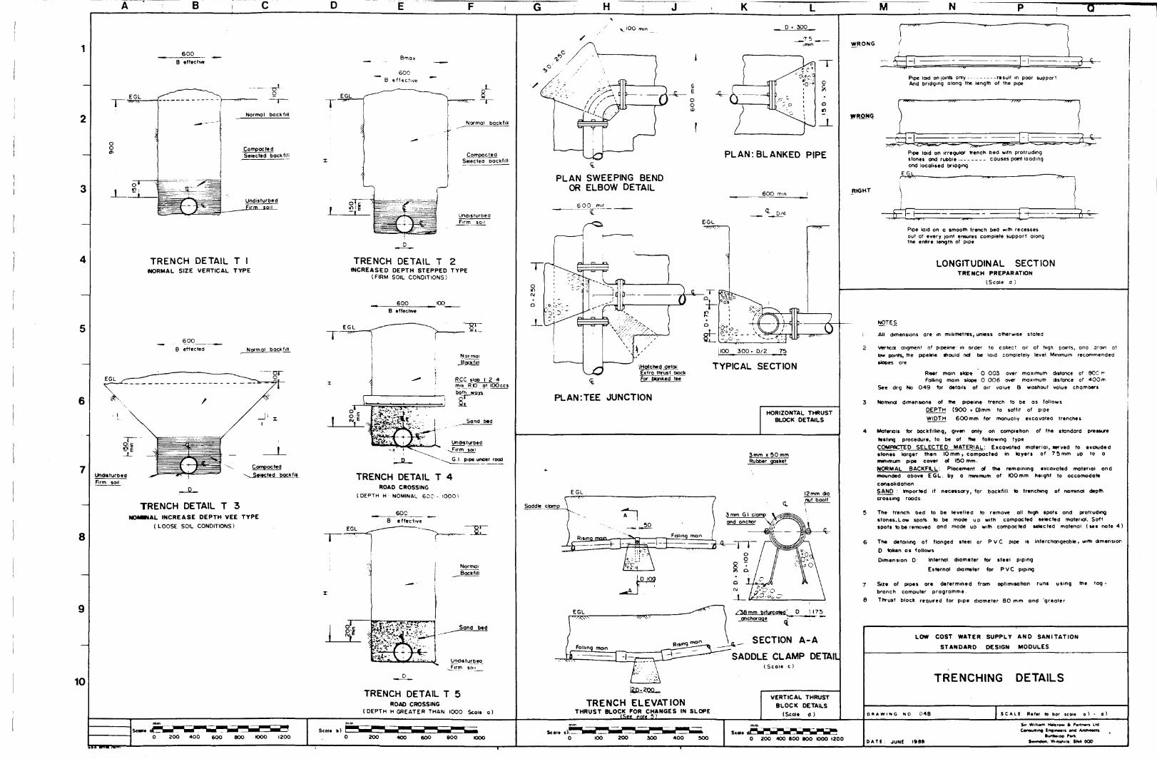
B H K M N
6 0 0
B effective
1
006
1
EGL
150
i
y— ^
Normal backfill
CompactedSelected backfill
Undisturbed
TRENCH DETAIL T INORMAL SIZE VERTICAL TYPE
600
B effected
EGL
Normol backfill
ar
Firm soil
TRENCH DETAIL T 3N0MMAL INCREASE DEPTH VEE TYPE
(LOOSE SOIL CONDITIONS)
8
10
Bmai
Normal backfill
CompactedSelected bockfill
UndisturDea
TRENCH DETAIL T 2INCREASED DEPTH STEPPED TYPE
(FIRM SOIL CONDITIONS)
600 COB affective
EGL
TRENCH DETAIL T 4ROAD CROSSING
(DEPTH H NOMINAL 6 0 0 - I000)
600B effective
TRENCH DETAIL T 5ROAD CROSSING
(DEPTH H GREATER THAN I000 Scale o)
I00 i D . 300_
PLAN: BLANKED PIPE
PLAN SWEEPING BENDOR ELBOW DETAIL
600 mm
TYPICAL SECTION
PLAN:TEE JUNCTION
HORIZONTAL THRUSTBLOCK DETAILS
3 mm » 5 0 mmRubber gasket
EGL
Q
SECTION A-A
SADDLE CLAMP DETAIL(Sca le c )
TRENCH ELEVATIONTHRUST BLOCK FOR CHANGES IN SLOPE
VERTICAL THRUSTBLOCK DETAILS
(Scale d )
WRONG
Pipe laid on joints only -result in poor supportAnd bridging along the length of the pipe
WRONG
Pipe loid on irregulor trench bed with protrudingstones and rubble causes port loadingond localised bridging
EGL
RIGHT
Pipe laid on a smooth trench bed with recessesout at every joint ensures complete support alongth» «nhr* lannlh ftf runsout at every joint ensurethe entire length of pipe
LONGITUDINAL SECTIONTRENCH PREPARATION
(Scale a )
NOTES
: All dimensions are in millimetres, unless otherwise stated
2 Vertical aligment of pipeline1 in order to collect air at high points, one drom attow points, the ptpehne should not be laid completely level Minimum recommended•topes ore
Riser main slope 0 003 over maximum distance of 900 r-Fallmg main slope 0 0 0 6 over maximum distance of 4 0 0 m
See drg No 0 4 9 for details of air value 8 washout value chambers
3 Nominal dimensions of the pipelne trench to be as followsDEPTH (900 • D)mm to soffit of pipe
WIDTH 6 0 0 m m for manually excovatea trenches
4 Maternls for backfilling, given only on completion of the standard pressuretotting procedure, to be of the foHowing typeCOMPACTED SELECTED MATERIAL: Eicovattd material, served to t idudedstones larger then 10mm. compacted in layers of 7 5 mm up to ominimum pipe cover of 150 mmNORMAL BACKFILL: Placement of th« remaining excavated material ondmounded obove EGL. by a minimum of tOOmm height to occomodottconsolidationSAND : Imported if necessary, for backfill to trenching of nomtnot depthcrossing roads
5 The trench bed to be levelled to remove all high spots and protrudingstones.Low spots to be mode up with compacted selected material. Softspots to be removed and made up with compacted selected matenal (see note 4 )
6 Th« detailing of flanged steel or P V C pipe is interchangeable, wrm dimension
D token as follows
Dim en sion D Internal diameter for steel piping
External diameter for PVC piping
7 S*zt of pipes are determined from optimisation runs using the tog -branch computer programme.
6 Thrust block requred for pipe diameter BO mm ond 'greater
LOW COST WATER SUPPLY AND SANITATION
STANDARD DESIGN MODULES
TRENCHING DETAILS
DRAWING NO 0 4 8
0 ZOO 400 600 800 1000 1200Scoit b)
200 400 GOO 800 OOO 100 200 300 400 300 0 200 400 600 BOO OOO 1200 DAT I : JUNE I98Sftuttarop P»ffe
WilMlura. SN4 OOD

6
8
10
450x450 fabricated^manhole cover andcollar, hinged and_secured by hasp andpodioc*
B C^Greater of: 600 or 3o.!50
H KR C.C slab I 2 4 mi*RIO at DO ccs both
| Ranged pipe lenqtr -' tsee note 5 ) -
81
length \see nD!e 5.
Flat brick loyer] 1 1 1 1
t
50mm bedding sand_115 baaamg sar.d
q_* 150,square"
SECTIONAL ELEVATION C I
Greater of200 or2d
SECTION A-A C 2
Greater of 6 0 0 or ( 40 + 150)
Greater oL_240 or 2 d .
SECTIONAL PLAN DETAIL ClSINGLE VALVE CHAMBER
SECTIONAL PLAN DETAIL C 2DOUBLE VALVE CHAMBER
Greater of 100"2?5or3o- -Tnir,
thrust blocksee detoiICZ
VALVE CHAMBER DETAIL C3
Supporting _ _K50block see mmdetail C2
Greater of6 0 0 pr(404l50)
VALVE CHAMBER DETAIL C 4
Supporting _ JPPblock see m i n
detail C2
600 or (4a »150)
VALVE CHAMBER DETAIL C 5Note
For changed flow directionthrust block data) c2 it required
FURTHER CHAMBER
ARRANGEMENTSI Scan b )
c ( FlojnT. T l riser
115
__ Greater of __eOOorU-b. 225 v
SECTIONAL ELEVATION DETAIL C 6SINGLE AIR VALVE CHAMBER
PLAN DETAIL C 6
M N
No adequate outfotidischarge to monhoieand pump to outfal[ f V "
WASHOUT VALVE CHAMBER DETAIL C 7
NoteDotted line details alternative arrangment underncreased moms depth
NOTE
I All dimensions are in miUtmetres, unless otherwise stated
2. For valve requirements at pump assembly plant refer todrawing numbers 0 0 4 - 0 0 6
3. For changes in verticol alignment
# Air release valve chambers are required at high pointsalong the mains pip* length , for tapping entrapped air pockets
• Washout mtv* chambers are required at all low points alongthe main* pip*length , For periodic flushing out off accumulateddeposit, Which may result in restricting flow
4 In long pipelines , valve chambers ore to be in installed toenable section* to be isolated for periodic inspection and / or repairs.to be placed every 3 5 k m
5 A short flanged pipelength accomodates convenient changing of old ordefective fittings for replacement of similar fittings but of differen*manufactured dimensions
LOW COST WATER SUPPLY AND SANITATION
STANDARD DESIGN MODULES
VALVE AND CHAMBER DETAILS
0 « A W I N G NO 0 4 9 to bar t c o i *
0 00 ZOO 300 400 500 600 TOO 800 900 1000Seal, b )
O 200 400 600 BOO 10001200 I40O D A T I : AUO 1986
S« W.lh.m Halcm t Pmnati LioConsulting Enomsara *nd Arehittcia
iw—ipp Part.Swmdon. » » M SN4 OQO

u
2 Number AfridevHond pump ossembhcs(see drg. no 022 )
K
6 0 0 n 6 0 0 Fobncoted monholecover secured in ploce byhasps ond padlocked & hingesee detoil drq No 007
75 mm thickcement concretelayer (see note 6 )
Minimum 150 mm depthFoundation sond
Plugged with a bockfiiof puddleiTclov (minthickness 150 mm)
Riser mom85 mm dio. PVC
ose tininFor requirement seenote 3 regarding potentioslouQhinq as indicated bybroken line
Riser main clomp
SECTIONAL FRONTSTONE MASONRY FEATURE
Scale to)
ELEVATION(SEE INSET)
Platform slab
8
10 Hard core crushedrubble in-ft I\_1orplatform enlargement
2500
6000 mnimum(see note 4)
PLAN VIEWScale (oi
Scole(o)400 BOO 1200 1600 2000
Seol.(c)O 10 20 30 «0 50 60 70 80 90 100
2 Number flfridevHond pump assemblies(see drq no 0 2 2 )
SECTIONAL SIDE ELEVATIONS c a l e ( a )
ALTERNATIVE DETAIL
BRICKWORK LINING
% Plotforfn slob
!
367 ' 1120 j | 1500
*cL IL 2L 31-4L 5
Apron slobtm)
0 0000 01700340 0510066
Top of Kerb( m )
00890 1060 1230 1400 155
L6L7L8L9LlO
Apron slab(m)
0 0660 05600450 010
lap of Pt at form(m)
0 0860 0760 0760 0760 086
APRON AND PLATFORMSETTING OUT DATA (SEE NOTE 2)Scale Ic)
M N O12mm thick rendering(see note 6)
Sjop.fi _of_ ground level governedby existing topogrophy
125 300 125 200 I
I!
a- 5t C_em_ent concreteFlot brick loyer; Mortor joint 1-2-4 mix
C C F,:;e- c - -
SECTION AAScale (b)
ALTERNATIVE DETAILFOR SECTION A AScale (b;
Clomp Flat metal 25 mm x 6mm
Riser mom89mm dig. PVC
Bifurcaied
9 5 mm dig, bolt SIDE VIEW
Riser moinO'D =89Cleoronce = 2Clamp thickness; I 2
103 IOC
RISER MAIN CLAMP DETAILScale (c)
NOTES:
I . All dimensions ore in millimetres unless otherwise stated
2 Important The setting out data is provided in order to assist m ensuring *no*all the required slopes to the apron and platform ore followed correct >Level L I is taken as the arbitrary datum 0.00
3. Base lining placed under conditions of loose sondy soils to protect oqc **"potential sloughing or under cutting as indicated by the broken ime a*" =
4 Minimum length of drain given as 6 metres owoy from the well point :rcto drain out to local nullah or field drainage systems.
5. The length of the unlined section of the well is dependant upon the so sond characteristics of the water bearing stratum and the instruction : 'the Engineer - in-charge
6 A cement polish finish on 12 mm rendering is to be given to plotforw.opron and dram surfaces
LOW COST WATER SUPPLY AND SANITATION
STANDARD DESIGN MODULES
IMPROVED DUG WELL
TWIN HAND PUMP ASSEMBLY
DRAWING MO 030
D A T ! APRIL
S O U R«(«f to Mr iioln {•] I t
S* WMwm HMcnw 4 P«

B H K M N
Af r idev hond pump
i Handle length vonabie| depending on depth of pump
Soakoge pit bock filledwith 25 ~ 150 0 groded stones*e note 2 for alternatives.
100 dio well casnginside 150 dia borehole
SECTIONAL FRONT ELEVATION AAScale ( a)
8oO
10000
oiom
Od
1500 1500
10PLAN VIEWScale ( o ,
Cone, pedestal
Cone, apron
L . , G.L
Cone, pedestal base
Riser pipe centrahser
63 O.D.PV.C. riser pipe
iOO mm. O.D.PV.C cosing pipe
Pump rodW.L
Rod centraltser
Bentomte/clay seal
Plunger
Gravef pack
Foot valve
Suction pipe
Nylon rope
iOOmm O.D.PV.C. screen
Bottom plug
150mm bore
SECTION THROUGH AFRIDEVHAND PUMP ON TUBEWELL
Not to Scale
NOTES
i AS dimensions are in millimetres unless otherwise slated.
2 Minimum length of concrete ivied dram to be 10 metres owoy fromthe edge of the apron area, it possible this should drain outto a local nullah or field dromoge system. If no local drainagepoint is available then a sooKoge pit should be constructedas shown.
3. A cement polsh finish on 12 mm renderrtg is to be given toplatform, apron and drain surfaces
A The plan and sectional views of the pump apron and dramhave been token from the Afndev Handpump tmtaltohanManual
LOW COST WATER SUPPLY AND SANITATION
STANDARD DESIGN MODULES
HAND PUMP ASSEMBLYON TUBE WELL
D R A W I N G NO 0 5 0 A S C A L E R a t e f to bor scales (o!
Seal* (A)
O 400 BOO 1200 1600 2000
m Hatcrow k P»nEnginMn sod•uMtorap P*n
DAT! JULY 1989

8
10
u
Afndcv Hona pump assembly
600xj500_Fabnc_attd mancover secured in place byhasp and pod lock & hingetee detoii drg No 007
75 mm thickcement concreteloyer t see note 6
Plugged wifn o bocfcfot puddled cloy (mmthickness 150 mm)
Riser mom clomp
SECTIONAL FRONT ELEVATIONSTONE MASONRY FEATURE (SEE INSET )
Scoie(o)
Slope ond requiredfjow pofh of wofcron opron s lob_(>ee setting out defoil
K
Hord core crushedrubble m fill forplot form enlarge ment
2500
6000 mnimum(see note 4 )
PLAN VIEWScale (o )
Afnd»y Hond pump assemblies
Riser mom clomp "\,",(see detoit
SECTIONAL SIDE ELEVATIONScale t o )
ALTERNATIVE DETAIL
BRICKWORK LINING
Platform tlob
367 1120 1500
Apron stab
L5 L-6
LIL2L3L 4L5
Apron slabIm)
0 000001 70 0340 05:0 066
Top of Kerb(m)
0 0890 1060 1230 1400 155
^ - '
L 6L 7L 8
L 9LIO
Apron t lobIm)
0 0660 0560 0450 010
Top of Platform( m )
00860 0760 0760 0760 086
APRON AND PLATFORMSETTING OUT DATA (SEE NOTE2)Scon (c )
M N:2mm thick rendering(see note 6 i
SoDe of g round level QOVS r^ecDy existing topographj
125 30C \2t 20C
SECTION A AScoie (b)
ALTERNATIVE DETAILFOR SECTION A AScale • b '•
Clomp Fiat metal 2 5 m m i 6mrr
89 mm a'O__PyC
9 5 mm dio bolt
OO
J_
_ - i 1 ^ , Bifurcate a oncnorcQe
Riser mom 0 0 =89CMOrance = ZClorno thickness^ 12
Fillet wela
20 C
RISER MAIN CLAMP DETAILScoie (c )
NOTES
1 . All dtmcnMKis ore in mibmctres unless otherwise stated
2 tmportont The setting out data is provided in order to assist in ensuring thatoil the required slopes to me apron and plot form Ore followed correct!*Level L I is taken as the arbitrary datum O 00
3 Base itnnq placed under conditions of loose sandy soils to protect agoms1
potential stoughing or under cutting as indicated by the broken line deton
4 Minimum length of drain given os 6 metres owov from the wen DO ml oneto drain out to local nullah or field drainage systems
5 The length of the unlmed section of the wen is dependant upon tnt sousand characteristics of the water bearing stratum and the instruction ofthe Engineer - in-cnorge
6 A cement polish finish on 12 mm rendering is to be given to platformapron and drain surfaces
LOW COST WATER SUPPLY AND SANITATION
STANDARD DESIGN MODULES
IMPROVED DUG WELL
SINGLE HAND PUMP ASSEMBLY
DRAWING NO 051 SC A l t Rtfar to Dor tcoM* [Q Ht>) ic )
40O BOO 1200 (600 2000 O 20 30 40 50 60 70 80 90 COScot«(c)
200 300 400 300
S* WNwm Htct+m A
D A T I JUNf I9BB mdon Writa*»r* SM4 000

B H K M N
Minimum
8OC
6 0 0 mm SQ monholeHinged cover with collqrsecufed_ by hosp ondpadtqcK
Kufcho diversionditcH (See typtco.layout detail )
2 5 0 » 8 0 DM beltmouthoverflow*
50mm Dip GlAir vent witnattached _ stoniesssteel mesn screes
Reinforcement Collector wing wallRl2 ot~l50mmcrs ! ' /
collar secured byhasp ana padlock"
ECM
Typical contour
(See note 6 }
Single gatevalve encT.o
PART CUT SECTIONAL ELEVATION
Anchor bloc* ana
Refer drg No 0 4 8
Overflew / dromogeoutlet to have an attachedstainless steel screen
Kutcha diversior
ditcr
_BgrDeg *>reboundary fence wU>ckcibie accesssee note Z )
6 2 * 300C
80mm DIP Gl Pipedroi noge / over f low ted Qminimum 10 m_ Qwoyfrom CLBJpmg to not uroi
or diversion _diteh.
R8 Links
8
Disc ho r ge by gravitytc: »torqge_ orto distributionjtSee note 3 )
irect
8 5 0
10
345
Baffle for•xcludingx>f silt todischarge line
; J f . ' • *.": f
i 1 •
,
46C ' !
• /
/
- \
50
TYPICAL LAYOUT DETAIL sca.e m
NOTES
1 AU. dimensions or* in mi Hi met res unless atnerwise stole o
2 t\ order to safeguard oga*»i possiMe polutton of the spring water me followingprecaution* are to be token
(a) Hoce puddle cloy in outer excavated trenches and above gravel pack (Seeelevation detail )
(b) Attach screens to the oir vent ond the drainage / overflow outle*
(c) Construct a diversion ditch to by-poss surtoce water as shown m typicallayout detail IT is good practice to plant hedges / trees ond grass on slopeto protect ogamst $o<i erosion
i, d J Fence off area from un out horsed persons ond wondering ammais
3 Requirement for balancing storage is dependant upon available vie*c ofspring and designed water demands
4 Dimensions H and h are determined per site conditions and the instruction of
the engineer— in -charge
5 Spring box may be constructed using stone or common brick masonr>t o dimensi on s shown
6 Typical contours are given orbitory volues for generohsed layout detail
OQ
COLLECTOR WING WALLSECTION A-A
Scale a '
PLAN Scole a)
LOW COST WATER SUPPLY AND SANITATION
STANDARD DESIGN MODULES
SPRING CAPPING DETAIL
NC 052
400 600 800 1000 1800Scalt b
2 3 4 5 6 7 8 9 10 DATE AUGUST 1988
Consulting tnginwft and 4ic*'t*c-s
»urO»«oe P«"Swviwton Wi**n>r« SN-» OOC

B H
6 0 0 * 6 0 0 _ G i Ringedmonhoje cover and collarsecured b~y padlock and ~hasp 1 Refer to Drg No 0 0 7 )
12 m m G ijntenor_ acce ssrungs placed at2 5 0 mm cc s with 150 mm
2 0 0 mm dtoDeiimoutn overflow
[50 mm bedding %ano
SECTIONAL FRONT ELEVATION '. Scale a
•25 mm dia G ijOirvent pipewTThTcr eer.
K
Outlet
in 80 Sops
M N
I in 80 Sope
DRY WELL- SECTION A-A
R 10 V, S DOTS
at 150 ccs bothwc^ys
1500 377 800 2 5 4
8
10
Quick
20_mrr piasterto intenc1""^ * " "^wet ~»e..
5012 mm plaster ( 4 maxboth faces
-t-
Overflow/drainageto natural outfaltfinal outlet to bescreeneo
vaive( Refer detaii Dra No 0 4 7
Al I f ^ X
—»-- - . '2 mm feoturol chorof er
SECTION PLAN
R 10 M S Cars
ot 2 0 0 c c s
b o t n wav
WET WELL SECTION B-B (scci* t
NOTES
1 All dimensions on* in miHmeters unless otherwise statea
2 Overflow pipe must be of larger diameter than inlet /outlet pipes
LOW COST WATER SUPPLY AND SANITATION
STANDARD DESIGN MODULES
BREAK PRESSURE TANK DETAIL
D R A W I N G NO
200 400 600 800 lOOO - 0 20O 400 60Q 800 tOOO 1200
S*t Wttliam mtcfow ft Pinncrt no»nd Architect*
OATI AUGUST 1988 W>*Wtit« SN4 OOD

u K ivr) in lOQ dromaoetowords keyhole
thin it\t vent byscreen (Stainless steel)
8
Odours esc ope bair stream draught
Wind direction andtypical air streams
Flies ottrocted byight re mo m trapped
Roof motcrIQIS to followusual type tn the area
IMPORTANT
Superstructure requires vent pipe lOOmm dm. or greater
The height is critical in effectingto hove o dork ongcool interior Thereforeneeds
Closure to entranceWell seaiea roofFace away from sunugh
ennonceo draught conditions(See inset detail and note 2 )
Unoer drought condit ionsone way flow of air
ffecting odour trap
Cement polished flopfinisn to ennancedrainoqe towards pi*
Ground level ! I
Dotted outline indicates| length of Key hole slobi varies according jo
soil type and foundingrequirements (sec note 4)
on the proiimity ofthe water fableand soil type
entry to pit fhesattracted towords
the only light sourceof the vent
Vent piperefer to note :
i *E. £
SECTIONAL PLANScale (b)
MainDiitn
Key
rein.. rein.
hole
6 mm6 fnm
slob
at
at
ISO CRS200 CRS
Leaching of fluids
i \ v
^ ^ w(See note 4)
SECTIONAL SIDE ELEVATIONScale l a )
10
NOTES
This option is used where it is importont to encourage smallchildren to use the latrine.They perceive that o ceramic ponrepresents less donqer of falling into the pit compared tothe keyhole design-
Ceramic panin place ofkeyhole feature
OPTIONAL FEATUREVIP LATRINE WITH
PAN
IMPORTANT
An adequately sealed roofingfor a darkened interior isrequired for effective fly trapconditions. Refer to section oxside elevation
Vent pipe
A typical site conditionwith latrine located byodjocent boundary wall
Cleoronce height (h) -Minimum 500 mm above highestsurrounding structure withinclose prommity of the lotnne
VENT PIPECLEARANCE DETAIL
KEYHOLE DETAILScale ( c )
CUTAWAY END ELEVATIONScale (a)
NOTES:
All dime
DOs and DONT s for VIP vent pipei-
00 _ Put the vent outside the superstructureDO _ Put it facing the sunDO — Make it 100 mm dia or largerDO — Make it as high os possible (See inset clearance detail)DO — Place it directly over the pitDO _ Cover it with stainless steel gauze
DONT _ Put it inside (It gets in the way of the pan)DON'T _ Have holes or cracks in it (Fhes can escape)DONT _ Cut it short (Air will not flow)DONT _ Cover the vent (tt excludes light and stops air flow)DONT _ Have a superstructure without a roof (Fhes will not be
at t racted to the vent)
It has been observed that the success of a latrine programme is asmuch dependent on good technology as it is on o good delivery systemWell designed and made latrines will NOT work satisfactorily UNLESSthey ore introduced to communities in o way that makes them want touse them properly. Thus this drawing should be read together with theManual tor low cost rural water supplies and sanitation* UNICEF , Quetta,1986
Dimension is determined according to soil type and founding requirements,as per site conditions and the decision of the Engineer-tn-cnorge
LOW COST WATER SUPPLY AND SANITATION
STANDARD DESIGN MODULES
SANITATION:VENTILATED IMPROVED
PIT LATRINED R A W I N G N O 0 5 4 S C A K R a f c r to OOf t c o i * t ( a ) . l t > )
?O0 4OO ftOO BOO COO KK) 200 100 400 9OO 600D A T E MARCH I9B8 $N4 000

A B U H K
8
10
ROOT mqierjais Jo__'piiowusu'oT type Tr Tfie oj^eo
Smooth cemen"sh on masonry
benchinDomes :erro cement _mannoie cover 2 5 mrr
PAN DETAILSECTION AAScale (b)
SECTION B-B Y-JUNCTION BOX DETAILFeaturing flow to pit Awith pipe to pit B blocked.Scale io
V1 Junction box with25 mm thicK Ferro cement
jnaji_hoie toyetJTiortqr seated
Domed Ferro cementSlob using two lovers
19 SWGoouoe 12.12 mesti
Sealed lining featuredNOTE:
egied mortarjointed bricK-
n It 5 mm DriCKwork
r^7O±13i f-elo^
:r". ~n 11 11 11 til1 ^
114mm dig PVC pipe(minimum slope h 101
jJ30_
LeochinQ pitettective ca£.a_cltiSOOJitres tRefer toOptional detgilj
honeycombed bricklining for leochtnq offtuios and gases>throuqn pit walls
PART SECTIONAL FRONT ELEVATIONScale (a)
114 mm dig PVC pipe
Y Junction box forregulating alternateflow conditions toleaching pits (SeeJunction boidetail)
Leaching of fluids and gosesthrough pit walls
PART SECTIONAL PLANScale (ol
CAPPED LEACHING PIT FORSELF SUPPORTING SOILS
Mortar ipinted
Leaching holes
Leaching of fluHjsond gos
STONE MASONRY LEACHING PIT LEACHING PIT
OPTIONAL DETAILS
The onentotion of thesuperstructure may beconstrucjed~cnrony ohqtiby providing g sweeping
90
Leochmg pit A
L t o c h t n g pit B
114 mm d i a i
benddetai l en largedview
OPTIONAL LAYOUTWITH ADJUSTMENTTO PAN ORIENTATION
N
i in lOO drainage
Cement po I ish
finish '0 5'aP
S Bend water seal
SECTIONAL SIDE ELEVATION sca.e w
Drainaae towards the panat I m 100 slope
O E5
425 i 200
1200
PLAN
PAN AND SLAB DETAILScale (b)
NOTES:
All dimensions ore in millimetres unless other wise stated
Components of a twin pit pour flush latrine— Superstructure— Pan and water seal
Pipework and Y-Junction boi— Twin leaching pits
Advantages of a twin pit pour flush latrine:Pan and water seal ore carefully designed for o low water requirement(I l i tre/ flush minimum) ond flushing by handThe shallow water seal is effective in preventing the passage of fliesand odoursOffset facilitates easy periodic emptying of the leaching pitTwin leaching pits olong with isolation via the Y-Junction box enablealt emote use and thereby allow for the drying of retained solids
LOW COST WATER SUPPLY AND SANITATION
STANDARD DESIGN MODULES
SANITATION
TWIN PIT POUR FLUSH LATRINE
D R A W I N G NO 0 5 5 S C A l f H«t«r lobor t c o i t t (o l . (b ) . ( c )
0 200 40O tOO BOO COO I ZOO 1400Scoit (b)
0 100 200 300 40O &OO «00 700 iOOScoit (e)
200 4O0 «00 *O0 1000 D A T E MARCH 1986 W M h t l SN4 000

Sir Wllliom Holcrow » Porlnart Ltd.Consulting Englnaart ond Archltactt.
Burdtrop PorkSwlndon Wlltthira. SN4 OOO
-
_
-
—
-
-
-
_
_
-
-
-
-
_
-
Mtmbtr
BASESLAB
WALLSA a C
BarMark
01
02
03
04
05
04
06
07
08
0 9
10
II
Typtslilt
RI2
RI2
RI2
RI2
RI2
RI2
RI2
RI2
RI2
RI2
RI2
RI2
Noof
mbr»
1
1
1
1
1
2
2
2
2
2
2
2
NoIn
tach
18
18
36
8
8
4
36
18
18
8
22
22
TotalNo
18
18
36
8
8
8
72
36
36
16
44
44
Ltngthof toch
bar*"m. m
3550
1550
2725
3900
2050
3900
1275
1200
4375
2175
550
3550
PROJECT: LOW COST WATER SUPPLY AND SANITATION STANDARD DESIGN MODULES
DRAWING TITLEI 11.4 CUBIC METER ( 2 5 0 0 GALLON) GROUND LEVEL STORAGE TANK.
Shopa All dimantiont ora Inoccordonct with BS 4 4 6 6untatt otharwltt t totad
3550
7 5 0
95 (
135070 (
3900
2050
3900
800
J 400
" ' 217570 (
2175
750
95 ("
3550
—
-
-
-
-
—
-
-
-
—
—
-
-
-
-
Member
WALLSB 8 D
ROOFSLAB
BorMork
0 5
0 6
07
0 8
12
13
14
15
16
17
18
BENDING SCHEDULE
Typt
still
RI2
RI2
RI2
RI2
RI2
RI2
RI2
RI2
RI2
RI2
RI2
Noof
mbrt
2
2
2
2
2
1
1
1
1
1
1
NoIn
toch
4
IB
9
9
22
30
6
2
18
6
12
Totol
No
8
36
18
18
44
30
6
2
18
6
12
Ltngthof torh
bar"m m
2050
1275
1200
4375
2750
2725
1775
2000
1550
2750
3550
Mtlrlc Rtv 0
Bor Schtdult Rtf 01
Org No 0 0 8 , 0 0 9
Oott MAY 198 B
S^ope All dimentiont are Inaccordance with 8$ 4 4 6 6unleit otherwlie stated
2050
800
1 400
217570
95
c1350
135070 (
j •—680 H
45inside Q J
\
1000
750
95 Q
2750
3550
Sir Wllliom Halcrow S Partntrt Ltd.Consulting Englnttr t ond Arehllactt.
Burdarop PorkSwlndon Wlltthlrt. SN4 OOD
-
-
-
-
-
-
-
-
-
-
-
-
-
Mambtr
BASESLAB
WALLS
BarMork
01
0 2
0 3
0 4
04
0 5
0 6
07
08
0 9
17
Typaa
•in
R 12
R I 2
R 12
R 12
RI2
R I2
RI2
RI2
RI2
RI2
RI2
Noof
mbrt
1
1
1
1
4
4
4
4
4
4
4
NoIn
9 6
4 8
4 8
1 6
4
48
2 4
2 2
2 2
4
2 4
TotolNo
96
4 8
4 8
16
8
192
9 6
8 8
8 8
8
9 6
Ltngthof tach
m. m
|
3550
1525
1550
3900
3900
1675
4425
3550
1550
2 200
1200
PROJECT: LOW COST WATER SUPPLY AND SANITATION STANDARD DESIGN MODULES
DRAWING TITLE 22-8 CUBIC METER ( 5 0 0 0 GALLON) GROUND LEVEL STORAGE TANK.
•Shape Alt dimension* or* inaccordance with BS 4 4 6 6
3550
7 5 070 (
7 5 0
95 f
3900
3900
8 50
2 20070 (
3550
7 5 095 (
2 200
1 400
/A 285
-
—
-
—
1 1
1
1
-
1—
-
-
—
—
Mtmbtr
ROOFSLAB
BarMark
10
II
12
13
14
15
16
BENDING SCHEDULE
Typt
RI2
RI2
RI2
RI2
RI2
RI2
RI2
NoOf
1
1
1
1
1
1
1
NoIn
48
40
8
48
8
4 0
2
Total
48
4 0
8
48
8
40
2
Ltngthof torh
bar"
m m
1525
3550
2875
1550
3200
3550
2000
Mtfrlc Rtv 0
Bar Schtdult Rtf 01
Org No 010 , Oil
Oatt MAY 19 8 8
Shape All tfimentiont are inaccor dance with 83 4 4 6 6
75070 r
3550
142570 f
7 5 095 r
3200
3550
1000
••' "
1000
to th« n«ir t i * 9 * 1

Sir Williom Halcro* • Par Inert LtdContulting Englneert ond Architect!.
Burderop PorkSwindon Wlllthlre. SN 4 OQO
-
-
-
-
-
-
-
-
-
-
-
-
Member
BASESLAB
WALLSA B B
Bor
Mork
01
0 2
OJ
04
05
O6
05
07
0 8
0 9
10
1 2
1 3
Typ«8
tile
R 12
R 12
H 12
R 12
R 12
R 12
R 12
R I 2
R 12
R 12
R 12
R 12
RI2
Noof
mbrt
1
1
1
1
1
1
2
2
2
2
2
2
2
NoIn
each
7?
4 8
72
48
CO C
D
4
72
36
36
30
30
8
TotolNo
72
48
!2
48
CO C
O
8
104
72
72
6 0
60
16
Ltnglhof each
b o r "m m
3550
5300
152b
1550
5750
3900
57 50
1675
1200
4425
5300
1550
2200
PROJECT
DRAWING
LOW COST WATER SUPPLY AND SANITATION STANDARD DESIGN MODULES
TITLE: 3 4 CUBIC METER (7,500 GALLON) GROUND LEVEL STORAGE TANK.
Shop* All dlmentlont are Inaccordance with BS 4 4 6 6unlett otherwlts t t o t t d
70
95
70
95
3550
5 300
^1)0
c750
5750
3900
5750
400
850
400
//f285
2200
c5300
75
c2200
-
_
-
-
-
-
-
-
-
-
Member
WALLSB S D
ROOFSLAB
BarMark
0 6
07
0 8
09
II
12
14
15
16
17
18
19
20
BENDING SCHEDULE
Type6
RI2
R 12
R 12
RI2
RI2
R 12
RI2
RI2
RI2
RI2
R 12
RI2
RI2
Noof
mbrt
2 ,
2
2
2
2
2
1
1
1
1
1
1
1
NoIn
each
4
4 8
2 4
2 4
30
30
7 2
6 4
8
48
40
8
4
Totol
No
8
96
4 8
48
60
60
72
64
8
48
40
8
4
Lengthof eorh
bor"m m
3 900
1675
1200
4425
3550
1550
1525
3550
2875
1550
5300
4 550
1150
Metric Rev 0
Bar Schedule Ref 01
Org No 012 , 013
Oote Moy 1988
Shape All dimentlont ore Inaccordance • U K BS 4 4 6 6unlett otherwise t t a t e d
3900
850
400
/ / \ 285
—HA2000
70 (
3550750
95 (
7 5 07O C
3550
1425
70 C
7 5 0
95
5 300
4550
1150
• Spoelflod to tho noaroot Bat •
• • Spcclfta* to tlio noartot t f t«»
Sir William Holcrow 8> Por Inert Ltd.Contulting Englneert ond Architects.
Burderop ParkSwindon Wiltthire SN 4 OOD
-
-
-
-
-
-
-
-
-
-
-
-
-
-
-
Member
BASE
WALLS
BorMark
01
0 2
0 3
0 4
0 5
0 6
0 7
0 8
09
Type
tilt
RI2
RI2
RI2
RI2
RI2
RI2
RI2
RI2
RI2
Noof
mbrt
1
1
1
4
4
4
4
4
Noin
each
128
64
64
6 8
34
34
34
JO
4
TotalNo
128
64
64
2 / 2
136
136
136
120
16
Lengthof each
b o r "m m
5000
1675
1700
1800
1175
5000
4475
1600
2200
PROJECT: LOW COST WATER SUPPLY AND SANITATION STANDARD DESIGN MOOULES
DRAWING TITLE: 45.5 CUBIC METRE (10,000 GALLON) GROUND LEVEL STORAGE TANK.
Snope Allaccordance
dimemlont ore inwith BS 4 4 6 6
5000
120
145
)
120
145
8 0 0
8 0 0
9 0 0
300
385
5000
2200
7 5 0
2 200
-
-
Member
ROOF
BorMork
10
1 1
12
13
1 4
1 5
BENDING SCHEDULE
Type8
l i te
RI2
RI2
RI2
RI2
RI2
RI2
NoOf
mbrt
1
1
1
1
1
1
NoIn
eoch
120
68
8
68
8
2
Totol
No
120
68
8
68
8
2
Longthof each
bar"m m
5000
1675
4375
1700
4300
2000
Metric Rov 0
Bar Schedule Ref CM
Org No. 014 , OlS
Dots JUNE 8 8
Shops All dlmentiont ore Inaccordance with BS 4 4 6 6unlett otherwise t to tsd
5000
8 0 0
120
2150
120
8 0 0
145
4300
1000

-
-
-
_
-
-
-
-
-
Sir Wiltiom Holcrow B Par Inert Lid.Contulting Englneert ond Architect!.
Burderop PorkSM ndon Wiltshire. SN 4 OOO
Mimbir
BASE
WAI 1 c:
A a c
BarMark
01
I).1
03
04
n^
06
08
10
12
13
Type
a•lit
RI6
MM.
RI2
RI2
R 16
RI2
R I6
R I6
R 12
RI2
Noof
mbri
1
1
1
1
p
2
2
2
2
2
NoIn
«och
108
I ' l l )
74
74
104
52
52
4
3 4
30
TotalNo
108
inn
74
74
2O8
104
104
8
c o
60
Ltngthof each
b a r "m m
5000
I9M)
7550
1700
I7OO
1150
4450
2200
7550
1700
PROJECT: LOW COST WATER SUPPLY AND SANITATION STANDARD DESIGN MODULES
DRAWING TITLE: 68 .3 CUBIC METRE (15,000 GALLON) GROUND LEVEL STORAGE TANK.
Shop* All dlmontlont oro Inaccordance with BS 4466unli t i otherwttt ttotod
5000
950
l?n f
7550
800
145
1000
1 300
- A 3652200
120 r
2200
7550
800
145
-
_
—
—
t-
-
—
_
—
-
-
-
-
Member
WALLS
B S D
ROOF
BarMark
0 6
0 7
0 9
10
11
13
14
15
16
17
18
19
20
BENDING SCHEDULE
Typ«
a• It!
RI2
RI2
RI2
RI6
RI2
RI2
RI2
RI2
RI2
RI2
RI2
RI2
RI2
NoOf
mbri
2
2
2
2
2
2
1
1
1
1
1
1
1
NoIn
ooch
35
ro
35
4
34
30
104
96
8
7 0
60
10
2
Total
No
70
140
70
8
68
60
104
96
8
7 0
60
10
2
Lengthof ooch
bar"m m
1150
1800
4475
2200
5000
1700
1950
5000
4350
1700
7550
6850
2000
Mofrle Rov 0
Bar SchoduU Rof 01
Drg No 016, 0 i7
Oat* JUNE 8 8
Snapo All dimentlent oro Inaccordance with BS 4 4 6 6unlt l l otheralto ttotod
1 300
/ / I 385
9 0 0
2200120
2200
5000800
145
120
950
50002150
120
800
145
7550
6850
1000
• • tpctfftttj •• Ik* »•«••! ! • • «
Sir Wllllom Holcrow a Portntri Ltd.Contulting Englneert ond Architect!.
Burderop PorkSwindon Wiltthirt. SN 4 OOD
-
-
-
-
:
-
-
-
-
-
-
-
Member
BASE
WALLS
A a c
BarMark
01
0 2
03
04
0 5
0 6
0 8
1 1
12
13
Type
a
RI6
RI2
RI6
RI2
RI6
RI2
RI6
RI2
RI2
RI6
Noof
mbrt
1
1
1
1
2
2
2
2
2
2
NoIn
eoch
140
144
140
72
136
68
68
68
28
8
TotalNo
140
144
140
72
272
136
136
136
56
16
Lengthot each
bar'*m.m
5000
5350
18 50
1600
1625
1 150
4 4 5 0
5 3 5 0
1700
2 2 0 0
PROJECT: LOW COST WATER SUPPLY AND SANITATION STANDARD DESIGN MODULES
DRAWING TITLE: 91.0 CUBIC METRE (20,000 GALLON) GROUND LEVEL STORAGE TANK.
Shopo All dimentlont are Inaccordance with BS 4466unlett olherwlte ttated
5000
5350
120
145
I
120
145
9 0 0
(
7 5 0
1000
300
| 385
2200
(
5350
8 0 0
2200
—
-
—
—
—
—
—
-
-
-
-
-
Member
WALLS
B S D
ROOF
BarMark
0 6
07
09
10
12
14
15
16
17
IB
19
2 0
BENDING SCHEDULE
Typea
tlie
RI2
RI2
RI2
RI2
RI2
RI6
RI2
RI6
RI6
RI2
RI2
RI6
NoOf
mbrt
2
2
2
2
2
1
1
1
1
1
1
1
Noin
ooch
34
6 8
34
34
28
136
68
128
6
8
128
2
TotOl
NO
68
136
68
68
56
136
68
128
6
8
128
2
Lengthof eoch
bor*'m m
1150
1500
4475
5000
1700
1850
1675
5000
4350
4600
5350
2000
Metric Roy 0
Bar Schedule Rof 01
Org No 018 ,019
Date JUNE 8 8
Shape All dimentlont are inaccordance tilth BS 4 4 6 6unlett other*.te ttated
1 300
—«
120
/[ 385
1000
2200
5000
8 0 0
145
120 (
145
900
800
5000
120 (2150
4600
5350
1000
• • ••*•*'*•* *• '*• n««r««t 26«m

Sir Wllllom Holcrow » Partners Ltd.Consulting Englntort and Archlttctt.
Burdtrop ParkSwindon Wlltthlrt. SN 4 OOD
-
-
1 1
1
1
-
-
-
-
1 1
1
1
Mtmbtr
BASE
WALLS
BarMark
01
02
03
04
05
06
07
08
09
Typtft
slit
RI6
RI6
R I6
RI6
RI6
RI6
RI6
RI6
RI2
Noof
mbrt
1
1
1
4
4
4
4
4
4
NoIn
tach
160
80
6
68
34
68
34
34
34
TotalNo
IRO
80
8
272
136
272
136
136
136
Ltngthof tach
bar**m. m
5700
1700
1725
2200
1200
2850
4900
2000
850
PROJECT: LOW COST WATER SUPPLY AND SANITATION STANDARD DESIGN MODULES
DRAWING TITLE: 25 SQUARE METRE SLOW SAND FILTER REINFORCEMENT DETAILS-
/Shopt All dimensions art In /accordanct with BS 4466 /unless othtrwltt stattd *
5700
160
195
-2
800
800
1100
300
A 425
2850
4900
145
110
950
400
c
-
-
-
1 1
1
1
1
1-
—
-
1 1
I 1
Mambtr
INLETCHAMBER
BENDING SCHEDULE
BarMark
10
II
Typt
lilt
RI2
RI2
NoOf
mbrt
1
1
NoIn
tach
8
15
Totol
No
8
15
Ltngthof torn
bor"m m
1450
1200
Mtfrlc Rtv 0
Bor Schtdult Rtf 01
Org No 030 , 031
Oott JUNE 88
occordanct with BS 4 4 6 6unlt t i othftfwltc i to t td
700
625
Sir WIIHom Hatcrow B Portntrt Ltd.Consulting Englnttrt and Archlltctt.
Burdtrop PorkSwindon Wlltthlr*. SN 4 0 0 0
PROJECT: LOW COST WATER SUPPLY AND SANITATION STANDARD DESIGN MODULES
DRAWING TITLE: 5 0 SQUARE METRE SLOW SAND FILTER REINFORCEMENT DETAILS-
Mafrlc Rtv 0
Bar Schtdult R>f 01
Org No 032 , 033
Dolt JUNE 88
MimbirBarMark
Typo
a•in
Noof
mbrt
NoIn
• och
TotalNo
Ltngthof (ach
bar**
Shop*.All dlmtntlont ort Inoccordanct with BS 4466unl««» othtrwlt* t tottd
MtmbtrBarMork
TyptS
tlzt
Noof
mbrt
NoIn
tach
Totol Ltngthof torh
bar**m m
Shopt All dimtntlont ort Inaccordanct with BS 4 4 6 6unlttt othtrwltt t t a t td
BASE 01
02
03
04
05
RI6
R20
RI6
RI6
RI6
82
75
75
82
150
82
75
75
82
150
11000
6000
6000
2000
2050
WALLS
A 8 C
06
07
08
09
10
II
13
14
RI6
RI6
RI6
RI6
RI6
RI6
RI6
RIO
2
2
2
2
67
67
67
134
8
40
120
67
134
134
134
268
16
80
240
134
1650
1700
1700
2800
2850
9900
2200
850
11000
6000
WALLS
B 8. D
6000
8 5 0
310
3 4 0
8 5 0
06
07
08
09
12
14
RI6
RI6
RI6
RI6
RI6
RIO
2
2
34
34
34
68
40
34
68
68
68
136
80
68
1650
1700
1700
2800
4900
850
1200
2800
4 900
4 0 0
1200
INLET
CHAMBER
1200
2800
2850
15
16
I7o
b
c
d
RI2
RI2
RI2
RI2
RI2
RI2
I
2
2
2
2
10 10
2
2
2
2
1050
1375
1025
1025
1050
1050
775
525
745
755 [
765
7 7 5 1
9900
9 5
1100
1.70400
BENDING SCHEDULE > 9p«eirt«d '» (ht n«sr«t» {Sun

Sir Wllllom Holerow S Portntrt Ltd.Consulting Cnglnttrt ond Archlttett.
Burdtrop PorkSwindon WItUhiro. SN 4 OOD
-
-
-
-
-
-
-
-
-
-
-
Mtmbtr
BASESLAB
WALLSA a C
BorMark
01
0 2
0 3
0 4
0 4
0 6
0 7
0 8
0 9
10
1 1
Typta•lit
RI2
RI2
RI2
RI2
RI2
RI2
RI2
RI2
RI2
RI2
RI2
RI2
Noof
mbri
1
1
1
1
1
2
2
2
2
2
2
2
NoIn
• oeh
18
18
36
8
8
4
3 6
18
18
8
22
22
TotalNo
18
18
36
CD
CO
8
72
36
36
16
44
44
Ltngthof toch
bar**m.m
3550
1550
2725
3900
2050
3900
1275
1200
4375
2175
1550
3550
PROJECT: LOW COST WATER SUPPLY AND SANITATION STANDARD DESIGN MODULES
DRAWING TITLE: 11.4 CUBIC METRE ( 2 3 0 0 GALLON) CLEARWELL REINFORCEMENT DETAILS
Shapt All dlmtnilam art Inoceordanct with BS 4 466unlttt othtrwltt ttattd
3550
750
9 5
70
c1350
c3900
2050
3900
8 0 0
1 400
217570 (
2175
7 5 0
9 5 (
3550
-
-
-
-
-
-
-
-
Mimbir
WALLSB S D
ROOFSLAB
BENDING SCHEDULE
BorMork
0 5
0 6
07
08
12
13
14
15
16
17
18
TyptB
• In
RI2
RI2
RI2
RI2
RI2
RI2
RI2
RI2
RI2
RI2
RI2
Noof
mbrt
2
2
2
2
2
1
1
1
1
1
1
NoIn
• oeh
4
18
9
9
22
3 0
6
2
18
6
12
Total
No
8
3 6
18
18
44
30
6
2
18
6
12
Ltngthof torn
bar**m m
2050
1275
1200
4375
2750
2725
1775
2000
1550
2750
3550
Mtfrlc Rtv 0
Bor Schtdult Rtf CM
Org No 0 J 5 , 036
Oatt JUNE 86
Shopt All dimtndonf a r t Inaccordance with BS 4 4 6 6• n l t i t o t h t r w l i t t t o t t d
2050
J
70
95
8 0 0
400
I 285
2175
rV.
.1350
c1350
70 (
i »•
V.
680 'fi. N
45 inside C )T
1000
7 5 0
95 (
2750
3550
• l»«elfltd te fh* n«or««f S m *
«• Sp«c<fl«4 ' • " • • nt.«r»#r tSiem
th- Wllllom Holcrow » Portntrt Ltd.Consulting Cnglnttrt ond Archlttett.
Burdtrop PorkSwlndan WIIMhlrt. SN4 000
PROJECT: LOW COST WATER SUPPLY AND SANITATION STANDARD DESIGN MODULES
DRAWING TITLE: 22 -g CUBIC METRE ( 3 0 0 0 GALLON) CLEAR WELL REINFORCEMENT DETAILS
Mtfrle Rtv O
Bar Schtdult Rtf 01
Org No 037, 038
Oott JUNE 68
MtmbtrBorMark
Typt»•lit
Noof
mbrt
NoIn
taeh
TotalNo
Ltngthof toch
bar**m.m
Shapt AM dlmtniloni art Inaccardonet with BS 4466unltn othtrwlat ttattd
MtmbtrBorMark
TyptB
• lit
Noof
nbri
NoIn
• oeh
Total
No
Ltngthof tor.h
bar**
Shopt .A I I dimtnstont a r t Inaceordonct with BS 4 4 6 6unltift othtrwlst s t a t t d
BASE
01
02
03
RI2
RI2
RI2
88
44
4 4
88
44
44
4050
1425
1450
WALLS
04
05
06
07
08
09
RI2
RI2
RI2
RI2
RI2
RI2
18
36
18
26
22
72
144
72
52
88
16
1025
1600
4425
3550
1650
2200
4050700
c 70
700
9 5
400
285
800
220070
3550
8 0 0
95
2200
ROOF
0
1
2
3
4
RI2
RI2
RI2
RI2
RI2
15 RI2
BENDING SCHEDULE
36
58
36
36
58
1525
3550
2850
1550
2900
2000
750
C3550
1425
c750
2900
1000
70
70
95
fo th« n»OT«Jit

Sir Wllllom Holerow B Partners Ltd.Consulting Engineer* ond Architect*.
Burderop PorkSw ndon Wiltshire. SN 4 OOD
_
-
-
-
-
-
-
-
1 1
1
1
Member
BASESLAB
WALLSABC
BarMark
01
0 2
0 3
0 4
05
06
0 8
10
12
1 3
Typef»
site
RI2
RI2
RI2
RI2
RI2
RI2
RI2
RI2
RI2
RI2
Noof
mbrs
1
1
1
I
2
2
2
2
2
2
NoIn
each
8 4
84
64
64
36
72
36
34
3 0
4
TotalNo
84
84
64
64
72
144
72
68
6 0
3
lengthof each
bar**m. m
4350
1700
6100
1750
1025
1900
4400
5300
1550
2200
PROJECT: LOW COST WATER SUPPLY AND SANITATION STANDARD DESIGN MODULES
DRAWING TITLE: 34.1 CUBIC METRE (7500 GALLON) CLEARWELL REINFORCEMENT DETAILS
Shape All dimensions are Inaccordance with BS 4 4 6 6unless otherwise stated
4350
8 50
70 (
6100
8 5 0
9 5
h -1285
c3 0 0
2 8 5
9 5 0
220070 (
5300
7 5 0
95 (
2200
—
—
i
-
-
_
-
1 1
1
1
Member
WALLSB & D
ROOFSLAB
BENDING SCHEDULE
BorMork
0 5
0 7
0 9
II
12
13
14
15
1 fi
17
18
19
2 0
Type9
site
R 12
RI2
RI2
RI2
RI2
RI2
RI2
RI2
RI2
RI2
RI2
R I 2
R I2
Noof
mbrs
2
2
CVJ
2
2
2
1
1
1
1
1
1
1
NoIn
eoch
24
48
24
34
30
4
48
4 0
8
7 2
64
8
2
Total
No
4 8
9 6
4 8
68
60
8
48
4 0
8
72
64
8
2
lengthof eorh
b a r "m m
1025
1900
4425
3550
1550
2 200
1550
5300
4600
1800
3550
2875
2000
•
Metric Rev 0
Bor Schedule Ref 01
Org No 0 3 9 , 0 4 0
Date JULY 6 8
Shape All dimensions ars Inaccordance with BS 4 4 6 6unless otherwise stated
I I 3 0 0/ \ 285
2 8 5 9 5 0
2000
70 c3550
95 1
. 750r
2 200
75 0
95 f
5300
4finn
70 (
90 0r
35 50
70
IOO<
1425
3
f
• • Sp*dfl*)tf f* fht nt)«r«ft f6«m
Sir Wllllom Holerow S Par Inert Ltd.Consulting Engineer* ond Architect*.
Burderop PorkSwlndon Wiltshire. SN 4 OOD
PROJECT: LOW COST WATER SUPPLY AND SANITATION STANDARD DESIGN MODULES
DRAWING TITLE: 45-5 CUBIC METRE (10,000 GALLON) CLEARWELL REINFORCEMENT DETAILS
Metric Rev 0
Bar Schedule Ref 01
Org No 041 , 0 4 2
Date JUNE 8 8
Member
BASE
BarMark
WALLSABC8.D
01
0 2
0 3
ROOF
0 4
0 5
06
0 7
0 8
09
I 0
11
12
Type&
•lie
RI2
RI2
RI2
RI2
RI2
RI2
RI2
RI2
RI2
RI2
RI2
RI2
Noot
mbr*
NoIn
each
168
8 4
8 4
68
34
34
30
120
6 8
TotalNo
168
84
84
272
136
136
136
120
16
120
6 8
Langthof each
bar*"m. m
Shops.All dlm«n«lon« or« Inaccordance with BS 4 4 6 6unless olhtrwl t« stated
5800
1575
1600
1800
1175
5000
4475
1600
2200
5000
1675
4375
5800
750
120
145
750
5000
120
145
2200
7 5 0
2200
5000
8 0 0
120
2150I2O[
300
385
MemberBarMark
13
14
15
Typea
size
RI2
RI2
RI2
NoOf
nbrs
BENDING SCHEDULE
NoIn
eoch
6 8
Totol
No
6 8
Lengthof eorh
bar**m m
1700
4300
2000
Shape All dimentlom are Inoccoi donee with BS 4 4 6 6unlotc otherwise stated
800
145
4300
1000
la l h« rtsjor %%% 5 -
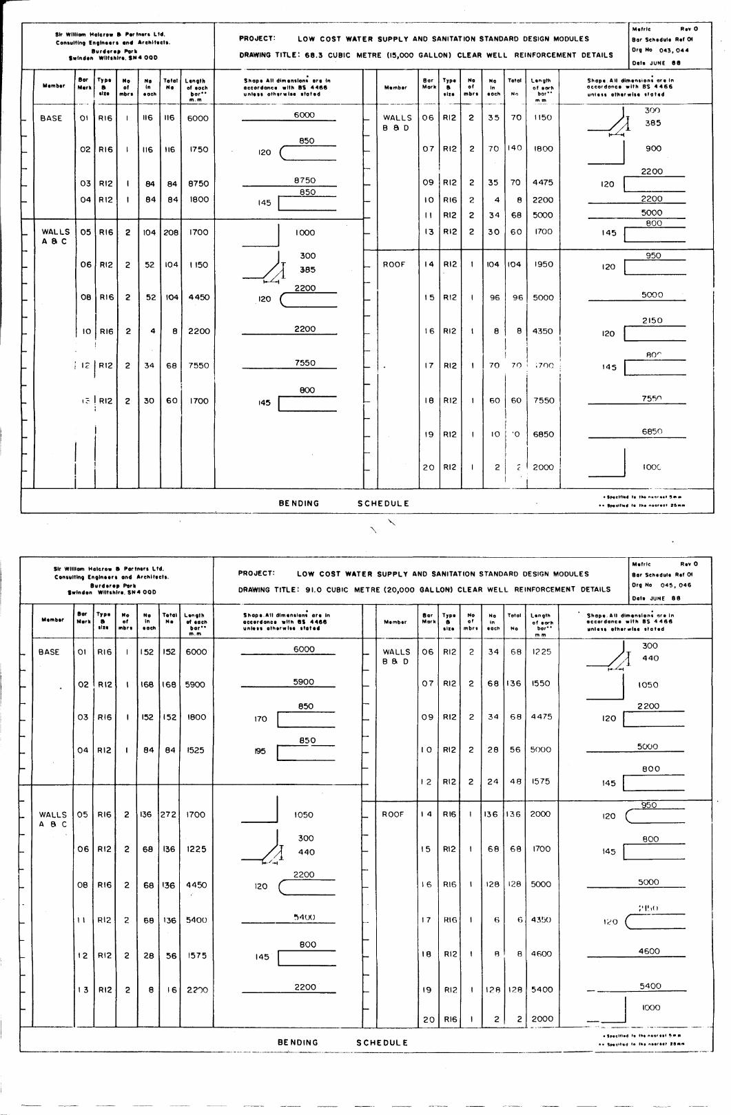
Sir Wllllom Halerow » Portnert Ltd.Contulting Engineer* and Arehlteett.
Burdtrtp PorkSwlndon Wlltthlrt. SN4 000
;
-
-
-
-
-
-
_
-
-
-
Mtmbtr
BASE
WALLSA 8 C
BarMark
01
0 2
03
04
05
06
0 8
10
12
1 C
Type
tltt
RI6
RI6
RI2
RI2
RI6
RI2
RI6
RI6
RI2
RI2
Noof
mbrt
1
1
1
1
2
2
2
CM
CM
2
NoIn
tach
116
116
84
84
104
52
52
4
34
30
TotalNo
116
116
84
84
208
104
104
8
68
6 0
Lengthof toch
b o r "m. m
6000
1750
8750
1800
1700
1 150
4450
2200
7550
1700
PROJECT: LOW COST WATER SUPPLY AND SANITATION STANDARD DESIGN MODULES
DRAWING TITLE'. 68.3 CUBIC METRE (15,000 GALLON) CLEAR WELL REINFORCEMENT DETAILS
Shopt All dlmtntlont are Inaccordanct with BS 4466unlett othtrwlte ttoted
6000
120
145
/
—CA120
850
(
8750
8 5 0
1000
3 0 0
I 385
2200
2200
7550
145
800
-
-
-
-
-
-
1 1
1 1
-
-
Mtmbtr
WALLSB S D
ROOF
•
BENDING SCHEDULE
BarMork
0 6
0 /
09
10
1 1
13
14
1 5
16
17
CD
CD
2 0
Typ*a
ti<t
RI2
RI2
RI2
RI6
RI2
RI2
RI2
RI2
RI2
RI2
RI2
RI2
RI2
Noof
mbrt
2
2
CM
CM
CM
2
1
1
1
1
1
1
1
NoIn
tach
3 5
7 0
35
4
34
3 0
104
96
8
70
60
10
2
Totol
No
7 0
140
70
8
68
6 0
104
9 6
8
Ltngthof twh
bor**m m
1150
1800
4475
2200
5000
1700
1950
5000
4350
70 .700
60
•o
7550
6850
2000
Mtfrle Rtv 0
Bar Schtdult Rtf CM
Drg No 043, 04 4
Oat* JUNE 68
Shopt AM dimtntioni a r t Inoccordonc* with 8S 4 4 6 6u n i t * * o th t rwl t t i t a t t d
- * *
120
300
]_ 385
9 0 0
2200
2200
5000
145
120
120
145
8 0 0
950
5000
2150
8 0 -
755 n
6850
IOOC
Sir Wllllom Halerow • Portntri Ltd.Contulting Englnteri and Architects.
Burdtrtp ParkSwlndon Wlltthlrt. SN 4 OOD
-
-
-
-
-
-
-
-
-
-
-
Mtmbtr
BASE
WALLSA & C
BarMark
01
02
0 3
0 4
05
06
08
1 1
12
1 3
TypeB
tilt
RI6
RI2
RI6
RI2
RI6
RI2
RI6
RI2
RI2
RI2
Noof
1
1
1
1
2
2
CM
C
M
CM
2
NoIn
152
168
152
8 4
136
6 8
68
68
28
8
TotalNo
I V
168
152
84
2 7 2
136
136
136
56
1 6
Lengthol each
b o r "m.m
6000
5900
1800
1525
1700
1225
4450
5400
1575
2200
PROJECT: LOW COST WATER SUPPLY AND SANITATION STANDARD DESIGN MODULES
DRAWING TITLE: 91.0 CUBIC METRE (20,000 GALLON) CLEAR WELL REINFORCEMENT DETAILS
*Shop*.All dlmtntlont art Inaccordance with BS 4466
6000
5900
850
170
850195 1
I1050
300
/A •"oH-'-i
2200120
145
C
MOO
800
2200
—
-
-
—
-
-
-
-
Member
WALLSB 8. D
ROOF
BENDING SCHEDULE
BarMork
0 6
0 7
0 9
1 0
1 2
1 4
15
1 6
1 7
18
19
2 0
Type
RI2
RI2
RI2
RI2
RI2
RI6
RI2
RI6
R16
RI2
Rl?
R16
Noof
2
2
2
2
2
1
1
1
1
1
1
1
NoIn
3 4
6 8
34
2 8
2 4
136
6 8
128
6
B
2
Total
6 8
136
6 8
5 6
4 8
136
6 8
128
6
8
2
Lengthof torn
m m
1225
1550
4 475
5000
1575
2000
1700
5000
43130
4600
5400
2000
Mefrle Rev 0
Bor Schedule Ref 01
Org No 045, 046
Date JUNE 8 8
Shopt AM dlmantion* ort inoccordonct with BS 4 4 6 6
J
120
145
120
145
, « ,
300
] 440
1050
2200
5000
8 0 0
9 5 0
(
8 0 0
5000
<
'.'ISO
4600
5400
1000