draft - cwc.ca.gov 2009_usjrbsi draft slis...figure 1. potential temperance flat rm 274 reservoir...
TRANSCRIPT


U.S. Department of the Interior Bureau of Reclamation DRAFT August 2009
DRAFT Temperance Flat RM 274 Reservoir Selective Level Intake Structure Enhanced Appraisal Technical Memorandum Upper San Joaquin River Basin Storage Investigation Prepared by U.S. Department of the Interior Bureau of Reclamation Mid-Pacific Region


Draft Temperance Flat RM 274 Reservoir SLIS Enhanced Appraisal TM
Contents
Introduction ...................................................................................................................................1 Temperance Flat RM 274 Reservoir Overview ...................................................................1 Selective Level Intake Structure Overview .........................................................................3
Enhanced Appraisal-Level Approach ...........................................................................................4 Reclamation Cost Estimate Levels ......................................................................................4 Data and Analyses................................................................................................................5
Design and Construction ...............................................................................................................7 Feature Description ..............................................................................................................7 Construction Activities ........................................................................................................9
Cost Estimates .............................................................................................................................11
Tables
Table 1. Cost Estimate Summary for the Selective Level Intake Structure on Temperance Flat RM 274 Reservoir .......................................................................................................11
Figures
Figure 1. Potential Temperance Flat RM 274 Reservoir .................................................................2 Figure 2. Potential Temperance Flat RM 274 Selective Level Intake Structure Location ..............8
DRAFT August 2009 – i
Upper San Joaquin River Basin Storage Investigation
ii – DRAFT August 2009
Abbreviations and Acronyms
cfs cubic feet per second
CIP cast-in-place
elevation xxx elevation in feet above mean sea level in NAVD 1988
HPU hydraulic power unit
Investigation Upper San Joaquin River Basin Storage Investigation
NAVD North American Vertical Datum
RCC roller-compacted concrete
Reclamation U.S. Department of the Interior, Bureau of Reclamation
RM river mile
SLIS selective level intake structure
TAF thousand acre-feet
TM Technical Memorandum

Draft Temperance Flat RM 274 Reservoir SLIS Enhanced Appraisal TM
Introduction
The Upper San Joaquin River Basin Storage Investigation (Investigation) is a joint feasibility study by the U.S. Department of the Interior, Bureau of Reclamation (Reclamation), and the California Department of Water Resources. The Investigation is one of five surface water storage studies recommended in the CALFED Bay-Delta Program Programmatic Environmental Impact Statement/Environmental Impact Report Record of Decision of August 2000. The purpose of the Investigation is to determine the type and extent of Federal, State, and regional interests in a potential project(s) in the upper San Joaquin River watershed to expand water storage capacity; improve water supply reliability and flexibility of the water management system for agricultural, urban, and environmental uses; and enhance San Joaquin River water temperature and flow conditions to support anadromous fish restoration efforts.
Temperance Flat RM 274 Reservoir Overview After a detailed plan formulation and site selection process, Temperance Flat River Mile (RM) 274 Reservoir was identified in the Reclamation October 2008 Plan Formulation Report as the site to be carried forward for more detailed analysis in the Draft and Final Feasibility Report. The purpose of this Technical Memorandum (TM) is to document the development of enhanced appraisal-level cost estimates of the selective level intake structure (SLIS) for the potential Temperance Flat RM 274 Reservoir, and associated design assumptions and concepts. The information in this TM will be integrated into a Draft Feasibility Design TM that will accompany the Draft Feasibility Report.
Temperance Flat RM 274 Reservoir would be created through construction of a dam in the upstream portion of Millerton Lake at RM 274. The dam site is located approximately 6.8 miles upstream from Friant Dam and 1 mile upstream from the confluence of Fine Gold Creek and Millerton Lake. Permanent features that would be constructed include a main dam with an uncontrolled spillway to pass flood flows, a powerhouse to generate electricity, and outlet works for other controlled releases. Upstream and downstream cofferdams would be required for river diversion, and to keep Millerton Lake isolated from the construction zone. Diversion tunnels would be required during construction to route river flows around the construction zone.
Figure 1 shows the extent of Temperance Flat RM 274 Reservoir and the surrounding area. At the top of active storage capacity (985 feet above mean sea level (elevation 985)), Temperance Flat RM 274 Reservoir would provide about 1,260 thousand acre-feet (TAF) of additional storage. Temperance Flat Dam would be about 640 feet high, from about elevation 365 in the bottom of Millerton Lake (San Joaquin River channel) at the upstream face to the dam crest at elevation 1,005.
DRAFT August 2009 – 1

Upper San Joaquin River Basin Storage Investigation
Figure 1. Potential Temperance Flat RM 274 Reservoir
2 – DRAFT August 2009

Draft Temperance Flat RM 274 Reservoir SLIS Enhanced Appraisal TM
Selective Level Intake Structure Overview An SLIS could be constructed upstream from Temperance Flat RM 274 Dam to enable releases from a range of reservoir elevations and temperaturesand thus manage the cold-water pool in the reservoir for releases to Millerton Lake. An SLIS is being evaluated as part of the Investigation because water temperature management is an important operational consideration. Temperature modeling analyses are also being performed as part of the Investigation, but are not included in this TM.
The potential Temperance Flat RM 274 SLIS would be an inclined, 800 -foot-long reinforced concrete structure located adjacent to and upstream from the entrance to the left bank diversion tunnel. The SLIS would consist of two low-level gates and three upper level ports. Each port would be protected with fixed trashracks. At the operating deck level of the SLIS, an intake gantry hoist would enable installing and removing of hydraulic cylinders and gates. An equipment building would house the gate hydraulic power unit and power and control panels.
DRAFT August 2009 – 3

Upper San Joaquin River Basin Storage Investigation
Enhanced Appraisal-Level Approach
The SLIS designs and cost estimates presented in this TM were developed at an enhanced appraisal-level of detail. Only standard structure types, consistent with current engineering principles and practices, were considered. All other design layouts, sections, and dimensions are based on standard practice, and experience with similar facilities. The structures presented are considered to be technically viable, based on available information. At the current level of design, limited efforts were made to optimize the design or minimize cost.
Reclamation Cost Estimate Levels Different levels of cost estimates are required to plan and fund projects. As a project moves through its development, each subsequent estimate level reflects increasing detail and refinement of the project features. Reclamation recognizes five different levels of construction cost estimates, as follows:
• Appraisal • Feasibility • Post-authorization/partial design • Prevalidation • Independent government
Cost estimates are typically developed in the chronological order shown, and each supersedes the previous estimate. They differ in degree of detail, refinement, use, and confidence, depending on the amount of certainty regarding the engineering and geological data that are available at the time the cost estimates are prepared.
Appraisal-level cost estimates represent the first level of project budgeting and are developed to determine whether more detailed project investigations or evaluations are justified. These estimates may be prepared from cost graphs, simple sketches, or rough general designs that use any site-specific design data that are readily available. These estimates are intended to be used to compare alternative features such as dam types, dam sites, and powerhouse or pumping plant capacities. Given the uncertainties regarding site conditions and potential changes in project configuration at the preliminary stage of project development, appraisal-levelcost estimates are generally not suitable for requesting project authorization or construction funding appropriations.
Feasibility-level cost estimates are based on information and data obtained during preconstruction field investigations. The preconstruction investigations (site-specific data collection and limited field explorations) typically provide a sufficient level of information to facilitate preparation of preliminary layouts and designs from which approximate quantities for each type of material, equipment, or labor can be estimated.
4 – DRAFT August 2009
Draft Temperance Flat RM 274 Reservoir SLIS Enhanced Appraisal TM
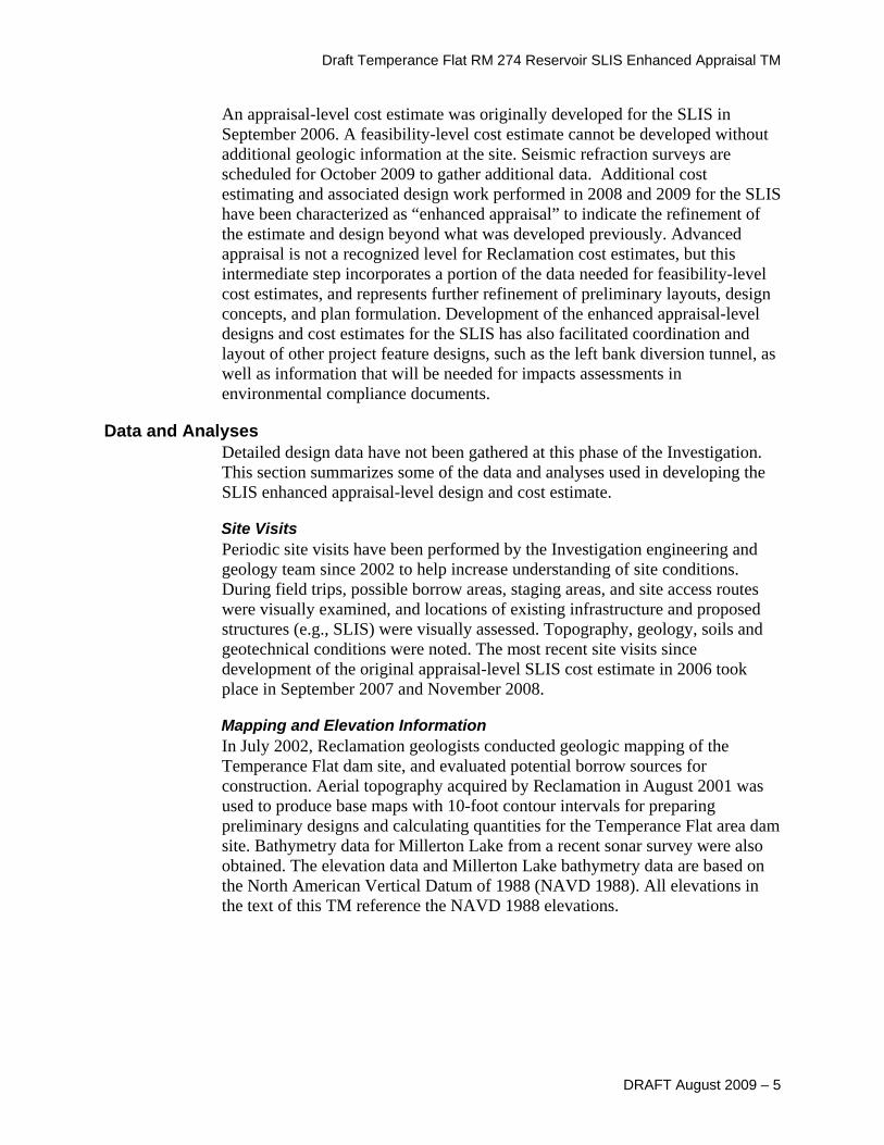
An appraisal-level cost estimate was originally developed for the SLIS in September 2006. A feasibility-level cost estimate cannot be developed without additional geologic information at the site. Seismic refraction surveys are scheduled for October 2009 to gather additional data. Additional cost estimating and associated design work performed in 2008 and 2009 for the SLIS have been characterized as “enhanced appraisal” to indicate the refinement of the estimate and design beyond what was developed previously. Advanced appraisal is not a recognized level for Reclamation cost estimates, but this intermediate step incorporates a portion of the data needed for feasibility-level cost estimates, and represents further refinement of preliminary layouts, design concepts, and plan formulation. Development of the enhanced appraisal-level designs and cost estimates for the SLIS has also facilitated coordination and layout of other project feature designs, such as the left bank diversion tunnel, as well as information that will be needed for impacts assessments in environmental compliance documents.
Data and Analyses Detailed design data have not been gathered at this phase of the Investigation. This section summarizes some of the data and analyses used in developing the SLIS enhanced appraisal-level design and cost estimate.
Site Visits Periodic site visits have been performed by the Investigation engineering and geology team since 2002 to help increase understanding of site conditions. During field trips, possible borrow areas, staging areas, and site access routes were visually examined, and locations of existing infrastructure and proposed structures (e.g., SLIS) were visually assessed. Topography, geology, soils and geotechnical conditions were noted. The most recent site visits since development of the original appraisal-level SLIS cost estimate in 2006 took place in September 2007 and November 2008.
Mapping and Elevation Information In July 2002, Reclamation geologists conducted geologic mapping of the Temperance Flat dam site, and evaluated potential borrow sources for construction. Aerial topography acquired by Reclamation in August 2001 was used to produce base maps with 10-foot contour intervals for preparing preliminary designs and calculating quantities for the Temperance Flat area dam site. Bathymetry data for Millerton Lake from a recent sonar survey were also obtained. The elevation data and Millerton Lake bathymetry data are based on the North American Vertical Datum of 1988 (NAVD 1988). All elevations in the text of this TM reference the NAVD 1988 elevations.
DRAFT August 2009 – 5

Upper San Joaquin River Basin Storage Investigation
Drilling Information Reclamation staff completed four borings near the potential Temperance Flat RM 274 site in September 2008 to gather additional data for evaluating feasibility-level designs and cost estimates. One of the borings was drilled near the lower portion of the potential SLIS location upstream from the left abutment. Geologic drilling activities were also performed at the Temperance Flat RM 274 dam site in 2006. The boring data were used to determine depth of overburden soils, and depths to competent rock on which to found the SLIS. The 2008 boring was extrapolated over the entire SLIS and left bank diversion tunnel portal sites.
6 – DRAFT August 2009

Draft Temperance Flat RM 274 Reservoir SLIS Enhanced Appraisal TM
Design and Construction
The following sections describe SLIS design and construction activities. SLIS design drawings are found in Attachment A.
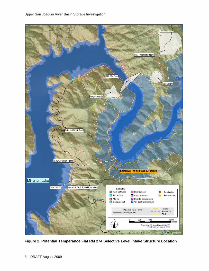
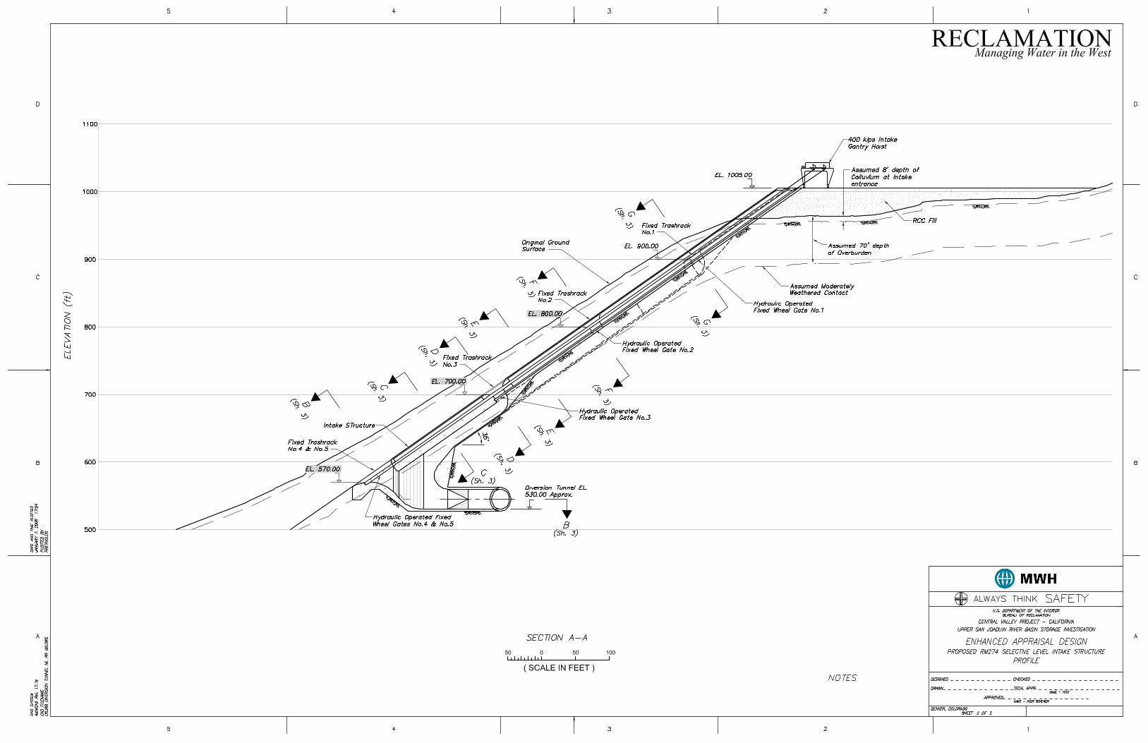
Feature Description The Temperance Flat RM 274 Reservoir SLIS would be an inclined reinforced concrete structure, located approximately 7,200 feet upstream of the dam, as shown in Figure 2, and would be located adjacent to and upstream from the entrance to the left bank diversion tunnel, which would be converted into a power tunnel at the conclusion of construction. The SLIS would consist of an 800-foot-long by 57-foot- to 82-foot-wide concrete structure, sloped at 35 degrees from horizontal. The concrete structures would be serviceable for in excess of 100 years.
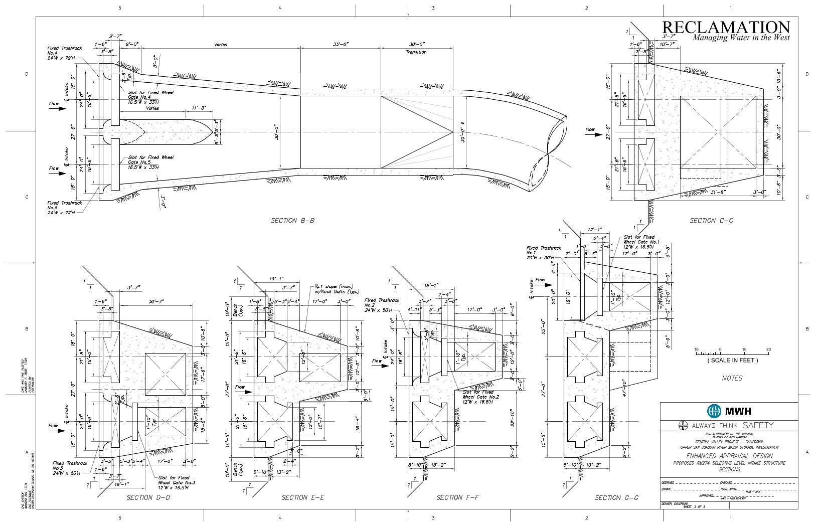
As currently planned, the SLIS would consist of two low-level fixed-wheel gates, which in combination are sized to pass a total of 20,000 cubic feet per second (cfs) during high flow conditions. Each low level gate would be 16.5 feet wide by 33 feet high and operated by submerged hydraulic cylinders connected to a hydraulic power unit (HPU) at the surface. In addition, three upper level ports would also be controlled by fixed-wheel gates, each sized to pass 1,700 cfs, the estimated peak power generation flow. This flow value is subject to change as more detailed designs and calculations are completed for hydropower and reservoir temperature operations.
The upper level gates would each be 12 feet wide by 16.5 feet high, and each would be actuated with submerged hydraulic cylinders connected to the surface-mounted HPU. Each gate and hydraulic cylinder operator would be capable of being installed and removed as a unit to the surface, through a wire-rope hoist and lifting beams that would travel on tracks down and up the inclined structure. Each port would be protected with fixed trashracks. Water through each lower port would flow directly into the power tunnel. Because the lower gates would also function to release higher flood flows, both are necessary, but only one would be opened, as necessary, for low pool temperature releases; the other would remain closed. Water through the upper ports would flow down an inclined concrete channel to the power tunnel at the base of the SLIS.
DRAFT August 2009 – 7
Upper San Joaquin River Basin Storage Investigation
Figure 2. Potential Temperance Flat RM 274 Selective Level Intake Structure Location
8 – DRAFT August 2009

Draft Temperance Flat RM 274 Reservoir SLIS Enhanced Appraisal TM
At the operating deck level of the SLIS at elevation 1,005, there would be an intake gantry hoist to enable installing and removing hydraulic cylinders and gates. The hoist may also be fitted with a trash raking head to allow cleaning of debris from the trashracks. At elevation 1,005, there would also be an equipment building to house the gate hydraulic power unit and power and control panels. The pad at elevation 1,005 would be fenced, and about 150 feet wide by 200 feet long, which would be a sufficient size to allow access by delivery trucks and storage of equipment. The gates and hoisting equipment may need major maintenance in 20-25 years (painting, component replacement, etc.). Replacement of electrical and mechanical equipment is estimated to occur 75-80 years after initial installation, with intermittent maintenance and component replacement, as required.
After construction is completed of both the SLIS and dam, the left bank diversion tunnel would be converted to a power tunnel. This would be accomplished by installing a concrete plug in the upstream end of the diversion tunnel and constructing an interconnecting tunnel from the base of the SLIS to the diversion tunnel. This interconnecting tunnel, or crossover tunnel, would be about 450 feet long and 30 feet in diameter, with a finished concrete liner. The completed power tunnel would lead to a river outlet works (bypass valve structure) that could release a maximum discharge of 20,000 cfs, and would also lead to the proposed powerhouse.
Construction Activities The duration and timing of SLIS construction is estimated to be 24-30 months of year-round construction. Approximately 200,000 labor hours would be required for construction activities. A 200-square-foot work pad would be constructed at the ridge above the SLIS for staging. At the completion of construction, this work pad would be removed and the area restored and revegetated. A small access road would be built to tie into proposed access/haul roads (Figure 1). The cofferdam used to construct the diversion tunnel is anticipated to be used for SLIS construction. Low water periods in Millerton Lake would be used to construct the bottom of the SLIS. The higher portion of the SLIS (above elevation 580) is outside the influence of Millerton Lake levels and would be constructed during remaining periods of the year. Temporary features that would require decommissioning once construction is complete include scaffolding and the construction staging pad. Equipment that is anticipated to be used during SLIS construction is listed in Attachment B.
Construction of the SLIS would include extensive excavation for both the structure and access road. Approximately 30,000 cubic yards of colluvium and 119,000 cubic yards of shot rock are anticipated to be removed. An estimated 10,000 truckloads of excavated material would be either disposed of in sites identified for dam construction waste, disposed of at the toe of the cofferdams, or be used for aggregate in cofferdam, SLIS, or dam construction. Wire mesh and 20-foot-long anchor bolts would be used to stabilize the cut faces.
DRAFT August 2009 – 9

Upper San Joaquin River Basin Storage Investigation
Roller-compacted concrete (RCC) could be utilized for leveling concrete. The current layout of the operating pad requires a deep fill, upwards of 40 feet at its deepest area. This fill could be accomplished using RCC or, alternately, the pad could be enclosed with crib-type or other type retaining walls and use less expensive shot rock as fill material to bring the pad to grade. The advantage to using RCC is that it could be used as a test placement for RCC so that the contractor’s means, methods, and results can be optimized and approved before placing critical RCC for the dam. Reinforced, cast-in-place (CIP) concrete would be used for the SLIS structure, and includes prefabricating forms, installing steel reinforcement, setting and stripping forms and shoring, performing rock/concrete cleanup, pouring and curing, and patching/finishing work. A batch plant would be assembled on site to provide concrete. Materials similar to those used for the RCC dam would be used for concrete construction. Coarse concrete aggregate would be provided from the RCC aggregate quarry on the north side of the reservoir and potentially from structure excavations. Fine aggregate is anticipated to come from local sources. Approximately 20,000 truckloads of aggregates would be needed. In addition, cement and pozzolan (fly ash) would need to be imported and stored in portable silos on site.
Several gates and guides would be installed on the finished structure, as discussed in the feature description. Gates would be fitted with trashracks, and a gantry hoist would be installed to operate and maintain both gates and trashracks. A crossover tunnel would be constructed once the dam is completed to connect the SLIS with the diversion tunnel. A concrete tunnel plug would be installed in the upstream end of the diversion tunnel, followed by controlled blasting techniques to excavate a tunnel from the base of the SLIS to the diversion/power tunnel downstream from the concrete plug. Approximately 18,000 cubic yards of tunnel muck would be excavated from the crossover tunnel. Excavation would be followed by concrete lining of the tunnel.
After SLIS construction is completed, riprap would be placed along the upstream and downstream sides of the structure to topographically tie the existing ground contours to the structure and to aid in erosion control.
10 – DRAFT August 2009
Draft Temperance Flat RM 274 Reservoir SLIS Enhanced Appraisal TM
DRAFT August 2009 – 11
Cost Estimates
The enhanced appraisal-level cost estimate is equivalent to a Class 4 level-of-effort estimate, as defined by the Association for the Advancement of Cost Engineering. A Class 4 estimate is appropriate for preliminary screening of conceptual alternatives, with an assumed level of project definition between 1 percent and 15 percent, and accurate in the range of -15 percent to -30 percent on the low side to +20 percent to +50 percent on the high side. The employed pricing methodology is consistent with a parametric unit price approach. The SLIS enhanced appraisal-level cost estimate is summarized in Table 1. The estimate worksheet is found in Attachment C.
The estimated SLIS cost of $68.7 million shown in Table 1 includes only estimated line item costs. The estimated costs for the SLIS are inclusive of contractor’s overhead and profits and cover field indirect (i.e., general conditions) expenses. Construction equipment and field personnel mobilization costs and contingency allocations for scope growth or market conditions are excluded from the cost estimate. The excluded costs will be added to the final cost estimate once this TM is incorporated into the Draft Feasibility Design TM. Non-contract costs and escalation costs associated with the SLIS will be developed at a later date, and will also be included in the Draft Feasibility Design TM. The estimates of line item costs have been prepared from the best information available at the time the estimate was prepared.
Table 1. Cost Estimate Summary for the Selective Level Intake Structure on Temperance Flat RM 274 Reservoir
Item Estimated Cost1 Excavation $16.4M SLIS Structure $30.1M Gates, Guides, Trashracks, and Hoist $18.0M Crossover Tunnel $4.2M Total Item Cost $68.7M
Key: M = million
Notes: General. Final feature costs and resulting feasibility would depend on actual labor and material costs, competitive market conditions, and other variable factors, and should include escalation to the midpoint of construction in future feasibility-level estimates. Accordingly, the final feature cost will vary from the estimate. 1Costs are presented in May 2009 dollars. This enhanced appraisal-level cost estimate is preliminary, and subject to revision in the Draft Feasibility Design TM.

Attachment A Selective Level Intake Structure Enhanced Appraisal Designs Upper San Joaquin River Basin Storage Investigation
DRAFT August 2009


Attachment B Selective Level Intake Structure Enhanced Appraisal Equipment Estimates Upper San Joaquin River Basin Storage Investigation
DRAFT August 2009


Table 1. Equipment Assumptions Included in SLIS Cost Estimate.
Equipment Hours of Operation Equipment Hours of
Operation
Leveling Concrete Excavation 305 hsp Bulldozer ( Cat D8 ) 60 305 hsp Bulldozer ( Cat D8 ) 2,123 170 hsp Bulldozer ( Cat D6 ) 450 140 hsp Grader (Cat 140) 1,062 140 hsp Grader (Cat 140) 510 2.0 CY Backhoe ( Cat 330 ) 160 2.0 CY Backhoe ( Cat 330 ) 173 4.2 CY Backhoe ( Cat 245 ) 902 20-Ton (10 CY) Tandem Truck 173 5,000 Gallon Water Tanker 1,062 72-inch Towed Packer (SWHS340) 60 20-Ton (10 CY) Tandem Truck 1,180 5,000 Gallon Water Tanker 60 30-Ton Articulated Truck (Cat D300) 3,607 13-Ton Compactor 72 inches (Cat 553) 450 13-Ton Compactor 72 inches (Cat 553) 160 Tower 4-Lights 12 Hsp 900 Jackleg Drill 52 Lb 700 CIP Structure Concrete 3/4-Ton Pickup Truck 2x2 700 1/2-Ton Pickup Truck 4x4 1,331 600 CFM Diesel Compressor 700 15-Ton Pitman Boom Truck 233 900 CFM Diesel Compressor 350 225-Ton Crawler Crane (American 9310) 5,345 Crossover Tunnel 90 YPH Truck Mounted Concrete Pump 400 1/2-Ton Pickup Truck 4x4 338 Concrete Vibrator-Normal 800 120 YPH Trailer Mounted Concrete Pump 142 10 KW Generator Set (gas) 800 140 hsp Grader (Cat 140) 29 Gates, Trashracks, and Hoist 15-Ton Pitman Boom Truck 84 1/2-Ton Pickup Truck 4x4 133 20-Ton (10 CY) Tandem Truck 467 1-Ton Mechanic Truck 20 225 -Ton Crawler Crane (American 9310) 1,405 10 KW Generator Set (gas) 80 3-Boom Jumbo 496 15-Ton Pitman Boom Truck 23 3,000 Gallon Water Truck 117 1 CY Concrete Bucket (gravity) 40 305 hsp Bulldozer ( Cat D8 ) 117 225-Ton Crawler Crane (American 9310) 771 4 inch Electric Submersible Pump 1,326 900 CFM Diesel Compressor 332 4.5 CY Loader (Cat 966) 117 450 CFM Diesel Compressor 94 900 CFM Diesel Compressor 1,122 Concrete Vibrator-Normal 40 Grout Plant and Injection System 204 Sandblast Pot 332 Jackleg Drill 52 Lb 204 Riprap Tunnel 5 CY Scoop Tram 1,618 305 hsp Bulldozer ( Cat D8 ) 160 Tunnel Muck Skip 4 CY 2,802 2.0 CY Backhoe ( Cat 330 ) 80 Tunnel Scissor Truck 204 5,000 Gallon Water Tanker 80 Tunnel Ventilation Fan 30 inches 1,618
Key: 2x2 = two-wheel drive vehicle 4x4 = four-wheel drive vehicle CFM = cubic feet per minute CY = cubic yard hsp = horsepower KW = kilowatt Lb = pound YPH = cubic yards per hour


Attachment C Selective Level Intake Structure Enhanced Appraisal Cost Estimates Upper San Joaquin River Basin Storage Investigation
DRAFT August 2009


BUREAU OF RECLAMATION ESTIMATE WORKSHEET SHEET____ OF ____
FEATURE: PROJECT:Alternative: Temperance Flat RM 274 Reservoir Upper San Joaquin River BasinSubgroup D - Outlet Works Storage Investigation
REGION: MP PRICE LEVEL: Appraisal, 05/2009Dam Crest = 1005 Top of Active Storage = 985 FILE:
WOID: UPSJS Appraisal Estimate
PLAN
T AC
CO
UN
T
PAY
ITEM
DESCRIPTION CODE QUANTITY UNIT UNIT PRICE AMOUNT
0 Selective Level Intake Structure
1 Leveling Concrete - Unreinforced 45,000 CY 125.00$ 5,625,000.00$
2 Rock Excavation 149,000 CY 30.00$ 4,470,000.00$
3 CIP Structural Concrete 33,000 CY 600.00$ 19,800,000.00$
4 Reinforcing Steel 5,100,000 LB 1.35$ 6,885,000.00$
5 Crossover Tunnel 471 LF 9,000.00$ 4,239,000.00$ 6 Furnish & Handle Cement 21,820 TN 150.00$ 3,273,000.00$
7 Building for Gate Controls 1 LS 600,000.00$ 600,000.00$
8 Riprap 9,000 CY 75.00$ 675,000.00$
9 Gates and Guides 1 LS 12,000,000.00$ 12,000,000.00$
10 Traveling Gate/Trashrack Hoist 1 LS 6,000,000.00$ 6,000,000.00$
11 Trashracks 1 LS 5,100,000.00$ 5,100,000.00$
Subtotal Sheet 2 (Subgroup D - Outlet Works) $68,667,000.00 QUANTITIES PRICES
BY D. Thompson/T. Brown CHECKED E. Cabero BY T. Brown CHECKED J. Loucks
DATE PREPARED 1/21/09 PEER REVIEW D. Crone DATE PREPARED 04/24/09 PEER REVIEW D. Crone
