Download - Zdravko Boos

1
Zdravko BoosIntel European Research & Innovation Conference23rd October 2013
The Future View from RF Perspective

2
Outline:
RF Challenges
2G/3G/4G Solutions
5G requirements
Future View

3
Total Cellular Device Market by Application
156 208 235 223 201 181 163 146
1,0251,071 1,043 999
942 891 843 793
175300
480 610 730 838 939 1,0350
10
2845 55 63 70 78
50
75
95105
115122
127130
29
38
5368
85105
115125
1,451
1,726
1,9582,081
2,1712,258
2,3322,403
0
500
1,000
1,500
2,000
2,500
2009 2010 2011 2012 2013 2014 2015 2016
Grey handsets Traditional handsets SmartphonesTablets Netbooks NotebooksUSB Dongles Data Cards Other CEs
Mio.

4
RF Challenges
Multiple RATs (2G, 3G, 4G, BT, GNSS, WiFi…)
Frequency bands (4 in 2G, -> 40 in 4G, ? 5G)
Carrier aggregation (DL, UL, inter/intra, ….)
MIMO (2x2 -> 8x8)
Power consumption (< 40 mA in UMTS 0 dBm)
Chip area (cost)
PCB area (cost)
Component height
Number of antennas

5
RF Transceiver Requirements
How to come there?
3GPP rel.xx

6
SMARTi 3GE
550mm² PCB Area
Triple Mode 4 Band GSM/EDGE 3 Band UMTS/HSPDA 130nm CMOS
2008
SMARTi PM2
200mm² PCB Area
Dual Mode 4 Band GSM/EDGE 130nm CMOS
2005
SMARTi+
650mm² PCB Area
Single Mode 3 Band GSM/GPRS 0.35µm BiCMOS
2000
SMARTi UE2
280mm² PCB Area
Triple Mode 4 Band GSM/EDGE 5 Band UMTS/HSPA+ RX Diversity 65nm CMOS
2011
Moore‘s Law of Multiradio Integration:The SMARTi TRX Evolution
Triplication of # of bands and # of modes in a decade @ 1/3 of the space
Page 6

7
Block Diagram of the AnalogMultimode Multiband Transmitter
Supported modes:• GSM• EDGE• EDGEEvo• WCDMA• HSPA+• LTE…

8
TX concept evolution from Analog to Digital
• Reconstruction filter removed
• D/A combined with mixer
• PA driver removed
• APLL replaced with DPLL
• External TX SAW omitted
=> 17b RFDAC requirement
DPLL
(as in audio but at 100000 times higher freq.)

9
Digital Transmitter Block Diagram
DCO
mag
phaseFIL d/dt INT
FIL INT
DPLL
I
Q
NS
NS
RF
DAC
DIG
INT
V
3.09
Gain
control
C
O
R
D
I
C
D
S
P
Fixed clock domain Variable clock domain
For an highly competitive digital cellular transmitter 65 nm was a breakeven technology
10
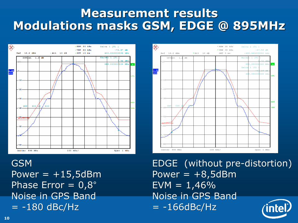
Measurement results Modulations masks GSM, EDGE @ 895MHz
GSMPower = +15,5dBmPhase Error = 0,8°
Noise in GPS Band = -180 dBc/Hz
EDGE (without pre-distortion)Power = +8,5dBmEVM = 1,46%Noise in GPS Band = -166dBc/Hz
Offset 1.2 dB
A
LVL
Att 10 dB*Ref 16.2 dBm
EXT
AVG
1 SA
Center 895 MHz Span 1 MHz100 kHz/
*
*
3DB
RBW 30 kHz
VBW 30 kHz
SWT 5 ms
-80
-70
-60
-50
-40
-30
-20
-10
0
10
SWP 500 of 500
1
Marker 1 [T1 ]
0.72 dBm
895.000000000 MHz
2
Delta 2 [T1 ]
-67.54 dB
-400.000000000 kHz
1
Delta 1 [T1 ]
-67.59 dB
400.000000000 kHz
EDGEMODM
Date: 24.JAN.2011 09:23:08

11
Measured TX far off noise in High Band / WCDMA
•Ftx = 1907 MHz•Output Power = +6 dBm•Spec: -157dBc/Hz @ DUX
80/95/190/400 MHz
A fully digital solution free of spurious

12
Intel Is Leading In RF CMOS Integration CMOS RF SoC With Integrated 3G PAs
XMM™ 6255 w/ SMARTi™ UE2pWorld smallest 3G modem
260mm²
• M2M • Internet of Things• Entry Smartphones
ES availableRamp Up E 2013

13
The World’s Smallest LTE Solution In 2013
XMM™ 7161 Multi-Mode Multi-Band LTE Modem
World‘s smallest LTE
Solution
• PCB area <400mm²
SMARTi™ m4G RF Module
• Including RF Transceiver,
Filters, Duplexer, Coupler
and Antenna Switches
7 x 5mm Multi-Mode-Multi-
Band PA
MMMB PA
SMARTi™m4G
XG716-M

14
Towards 5G: Mobile Data Traffic Growth
– System Capacity Requirements
– Network traffic load increasing by 65-100% CAGR
– Requires up to 2x increase in network capacity per annum
– > 100 higher traffic until 5G introduction in 2020
Ericsson Mobility Report, June 2013Excludes WiFi, VoIP, MTC
Cisco Visual Networking Index, Feb.`13
Ericsson: 100%+ CAGR
Cisco: 66% CAGR
Note 1: Assumes 85% CAGR in traffic.

15
Trends in Spectrum AvailabilityExample: Emerging U.S. Auctions

16
U.S. 3.5GHz Spectrum Access System (SAS)
Managed Spectrum Sharing
–U.S. Strategic National Objectives
–#1 – Release new spectrum potentially with new licensing regime
–#2 – Deploy high-capacity technologies – including small cell
–FCC Proposal – Citizens Broadband Service (CBS)
Band Status Band Bandwidth
Proposed 3350-3650 MHz 100 MHz
Potential 3650-3700 MHz 50 MHz

17
mm-Wave Frequency AllocationsInternational 60GHz plus U.S. LMDS Bands
Band(GHz)
BW(GHz)
Licensing
71-76 5.0 1. Licensing: databaseregistration, non exclusive.2. Allocation: 1.25GHz aggregable blocks3. Services: point-pointfixed services.
81-86 5.0
92-94 2.0
94.1-95 0.9
57-66 9.0
U.S. Allocations 70-80-90GHz Bands
BTA1
Lic-ense
Band(GHz)
BW(MHz)
BW(GHz)
A
27.5–28.35 850
1.150 29.1–29.25 150
31.075–31.225 150
B31.0–31.075 75
150 31.225–31.3 75
Note 1: BTA – Basic Trading Area
U.S. Allocations 28-31GHz LMDSFixed Point-Point Service
Band(GHz)
Structure
38.6-4014 x 50MHz Pairs(100MHz Total)
U.S. Allocations 39GHzFixed Point-Point Service
Band(GHz)
BW(GHz)
Jurisdiction Licensing
57-64 7.0 USA Unlicensed
57-64 7.0 Canada Unlicensed
59-66 7.0 Japan Unlicensed
57-64 7.0 S. Korea Unlicensed
57-66 9.0 Europe Unlicensed
International 60GHz Allocations

18
mm-Wave System DesignHistorical Perspective
J. Gardiner, “Microwave and mm-WAVE Technology Requirements…European 4th-Framework…”,
Microwave Symp. Digest, 1995
1995
J.J. O'Reilly, et al, “MODAL: an Enabling Technology for Wireless Access”, 1993. 4th-IEE Conf. Telecomm.
1993

19
Network Capacity EnhancementRelative Contribution – 2013-2020

20
Hypothetical 5G Device – 2020
–5G Era Devices – 2020
–Multi-RAT support including evolution of LTE and WiFi (WiGig)
–Support for 1 or more possible “new” 5G RAT’s
– Flexible resource-aggregating “cellular” transceivers, accessing >150MHz with up to antenna 8 ports
–New access to sub-6GHz spectrum and new aggregation modes

21
Summary
• Even with 5G definition just started it is clear that the best 3G/4G solution is prerequisite and enabler for the coming 5G mobile network
2G/3G/4G 5G
• Exponential mobile data traffic growth is a key driver for the 5th generation mobile networks


