
8/13/2019 Training Report on CCNA(Cisco Certified Network Associate)
http://slidepdf.com/reader/full/training-report-on-ccnacisco-certified-network-associate 1/94
A PRACTICAL TRAINING REPORTON
“CCNA”Submitted in the partial fulfillment of the requirements for the
award of the degree of
Bachelor of Technology
in“Computer Science & Enginnering”
SUBMITTEDTO:- SUBMITTEDBY:-
Mr. Deepak Goyal Pankaj GillAssociate Professor & Head 11/CSE/168CSE Department VCE, ROHTAKVCE, ROHTAK
VAISHCOLLEGEOF ENGINEERING(Affiliated to Maharshi Dayanand University, Rohtak)
ROHTAK – 124001
JULY-AUG-2013

8/13/2019 Training Report on CCNA(Cisco Certified Network Associate)
http://slidepdf.com/reader/full/training-report-on-ccnacisco-certified-network-associate 2/94
Certificate
This is to certify that practical training report entitle “ CCNA” done by
Mr. Pankaj Gill, Roll No. 11/CSE/168 of Vaish College of Engineering, Rohtak
towards partial fulfillment of the requirements for the award of the degree of
“Bachelor of Technology” in “C.S.E” is a bonafide record of the work carried
out by him under My Supervision and Guidance.
Date: AUTHORISED SIGNATORYPlace:

8/13/2019 Training Report on CCNA(Cisco Certified Network Associate)
http://slidepdf.com/reader/full/training-report-on-ccnacisco-certified-network-associate 3/94

8/13/2019 Training Report on CCNA(Cisco Certified Network Associate)
http://slidepdf.com/reader/full/training-report-on-ccnacisco-certified-network-associate 4/94
INDEX Page No.
CertificateAcknowledgement
Project Description 1
1. Basic Networking1.1 What is Network? 41.2 What is Topology? 6
1.3 Categories of Network 131.4 Network Architectures 161.5 Protocols 181.6 Transmission Media 201.7 Ethernet Products 261.8 Types of Servers 311.9 IP Addressing 331.10 Examining your Network with Commands 36
2. DNS(Domain Name Servers)2.1 Introduction 40
2.2 Operations 432.3 DNS Server Installation 462.4 DNS Server Configuration 502.5 Managing DNS Records 542.6 Disabling DNS Recursion 58
3. LAN Solution3.1 LAN Solution 603.2 Specification Sheet 623.3 Router 643.4 Routing Protocols 69
4. Firewall4.1 Introduction 734.2 Configuring the Firewall 74

8/13/2019 Training Report on CCNA(Cisco Certified Network Associate)
http://slidepdf.com/reader/full/training-report-on-ccnacisco-certified-network-associate 5/94
5. Intrusion Detection System(IDS)5.1 Introduction 77
6. WAN Solution6.1 Requirement 80
6.2 Solution 80
7. WLAN(Wireless LAN)7.1 Introduction 827.2 Topologies 83
8. Integrated Service Digital Network(ISDN)8.1 Introduction 868.2 ISDN Interfaces 878.3 ISDN Function Group & Reference Points 88

8/13/2019 Training Report on CCNA(Cisco Certified Network Associate)
http://slidepdf.com/reader/full/training-report-on-ccnacisco-certified-network-associate 6/94
TRAINING REPORT ON CCNA 2013
PANKAJGILL 11/CSE/168 P
a g e 1
Project Description
CCNA(Cisco Certified Network Associate ) is a certification from Cisco.
CCNA certification is a first-level Cisco Career certification. CCNA certification validates theability to install, configure, operate, and troubleshoot medium-size routed and switchednetworks, including implementation and verification of connections to remote sites in aWAN.
To achieve CCNA certification, one must earn a passing score on Cisco exam #200-120, orcombined passing scores on both the ICND1 #100-101 and ICND2 #200-101 exams. Passingthe ICND1 grants one the Cisco Certified Entry Networking Technician (CCENT) certification.Passing scores are set by using statistical analysis and are subject to change. At the
completion of the exam, candidates receive a score report along with a score breakout byexam section and the passing score for the given exam. Cisco does not publish exam passingscores because exam questions and passing scores are subject to change without notice.
The 200-120 CCNA is the composite exam associated with the Cisco Certified NetworkAssociate certification. This exam tests a candidate's knowledge and skills required to install,operate, and troubleshoot a small to medium size enterprise branch network. The topicsinclude connecting to a WAN; implementing network security; network types; networkmedia; routing and switching fundamentals; the TCP/IP and OSI models; IP addressing; WANtechnologies; operating and configuring IOS devices; extending switched networks withVLANs; determining IP routes; managing IP traffic with access lists; establishing point-to-point connections; and establishing Frame Relay connections.
The exams themselves include a mixture of question types. Multiple choice, drag and drop,testlets, and simulations are the most common.
The Available Exams
To receive the CCNA certification, one must pass either:
• the ICND1 Exam (100-101) and the ICND2 (200-101)• the combined CCNA Exam (200-120)
8/13/2019 Training Report on CCNA(Cisco Certified Network Associate)
http://slidepdf.com/reader/full/training-report-on-ccnacisco-certified-network-associate 7/94
TRAINING REPORT ON CCNA 2013
PANKAJGILL 11/CSE/168 P
a g e 2
The Material Covered In Each Exam
The ICND1 covers "Network Types, Network Media, Switching Fundamentals, TCP/IP, IPAddressing and Routing, WAN Technologies, Operating and Configuring IOS Devices, and
Managing Network Environments."
The ICND2 covers "Extending Switched Networks with VLANS, Determining IP Routes,Managing IP traffic with Access Lists, Establishing Point-to-Point connections, andEstablishing Frame Relay Connections." The combined CCNAcovers all topics covered underthe ICND1 and ICND2.

8/13/2019 Training Report on CCNA(Cisco Certified Network Associate)
http://slidepdf.com/reader/full/training-report-on-ccnacisco-certified-network-associate 8/94
TRAINING REPORT ON CCNA 2013
PANKAJGILL 11/CSE/168 P
a g e 3
CCNA T RAINING REPORT
1. BASICNETWORKING1.1 What is Network? 41.2 What is Topology? 61.3 Categories of Network 131.4 Network Architectures 161.5 Protocols 181.6 Transmission Media 201.7 Ethernet Products 261.8 Types of Servers 311.9 IP Addressing 331.10 Examining your Network with Commands 36

8/13/2019 Training Report on CCNA(Cisco Certified Network Associate)
http://slidepdf.com/reader/full/training-report-on-ccnacisco-certified-network-associate 9/94
TRAINING REPORT ON CCNA 2013
PANKAJGILL 11/CSE/168 P
a g e 4
1.1 What is a Network?A network is any collection of independent computers that communicate with one anotherover a shared network medium. A computer network is a collection of two or moreconnected computers. When these computers are joined in a network, people can sharefiles and peripherals such as modems, printers, tape backup drives, or CD-ROM drives.When networks at multiple locations are connected using services available from phonecompanies, people can send e-mail, share links to the global Internet, or conduct videoconferences in real time with other remote users. As companies rely on applications likeelectronic mail and database management for core business operations, computernetworking becomes increasingly more important.
Every network includes:
• At least two computers Server or Client workstation.• Networking Interface Card's (NIC)• A connection medium, usually a wire or cable, although wireless communication
between networked computers and peripherals is also possible.• Network Operating system software, such as Microsoft Windows NT or 2000, Novell
NetWare, Unix and Linux.
Very common types of networks include:1. Local Area Network (LAN)2. Wide Area Network (WAN)3. Metropolitan Area Network (MAN)4. Personal Area Network (PAN)
1. Local Area Network
A Local Area Network (LAN) is a network that is confined to a relatively small area. It is
generally limited to a geographic area such as a writing lab, school, or building.
Computers connected to a network are broadly categorized as servers or workstations.Servers are generally not used by humans directly, but rather run continuously to provide"services" to the other computers (and their human users) on the network. Servicesprovided can include printing and faxing, software hosting, file storage and sharing,messaging, data storage and retrieval, complete access control (security) for the network'sresources, and many others.
On a single LAN, computers and servers may be connected by cables or wirelessly. Wireless
access to a wired network is made possible by wireless access points (WAPs). These WAP

8/13/2019 Training Report on CCNA(Cisco Certified Network Associate)
http://slidepdf.com/reader/full/training-report-on-ccnacisco-certified-network-associate 10/94
TRAINING REPORT ON CCNA 2013
PANKAJGILL 11/CSE/168 P
a g e 5
devices provide a bridge between computers and networks. A typical WAP might have thetheoretical capacity to connect hundreds or even thousands of wireless users to a network,although practical capacity might be far less.
2. Wide Area Network
Wide Area Networks (WANs) connect networks in larger geographic areas, such as Florida,the United States, or the world. Dedicated transoceanic cabling or satellite uplinks may beused to connect this type of global network.
Using a WAN, schools in Florida can communicate with places like Tokyo in a matter of seconds, without paying enormous phone bills. Two users a half-world apart withworkstations equipped with microphones and a webcams might teleconference in real time.A WAN is complicated. It uses multiplexers, bridges, and routers to connect local and
metropolitan networks to global communications networks like the Internet. To users,however, a WAN will not appear to be much different than a LAN.
3. Metropolitan area network
A metropolitan area network (MAN) is a computer network in which two or morecomputers or communicating devices or networks which are geographically separated but insame metropolitan city and are connected to each other are said to be connected on MAN.The limits of Metropolitan cities are determined by local municipal corporations and wecannot define them. Hence, the bigger the Metropolitan city the bigger the MAN, smaller ametro city smaller the MAN. The IEEE 802-2002 standard describes a MAN as being.
4. Personal area network
A personal area network (PAN) is a computer network used or communication amongcomputerized devices, including telephones and personal digital assistants. PANs can beused for communication among the personal devices themselves (intrapersonalcommunication), or for connecting to a higher level network and the Internet (an uplink).A wireless personal area network (WPAN) is a PAN carried over wireless
network technologies such as IrDA, Wireless USB, Bluetooth, Z-Wave, ZigBee, or even BodyArea Network. The reach of a WPAN varies from a few centimeters to a few meters. A PANmay also be carried over wired computer buses such as USB and FireWire.
5. VPN (Virtual Private Network)
VPN uses a technique known as tunneling to transfer data securely on the Internet to aremote access server on your workplace network. Using a VPN helps you save money byusing the public Internet instead of making long–distance phone calls to connect securelywith your private network. There are two ways to create a VPN connection, by dialing an
Internet service provider (ISP), or connecting directly to Internet.
8/13/2019 Training Report on CCNA(Cisco Certified Network Associate)
http://slidepdf.com/reader/full/training-report-on-ccnacisco-certified-network-associate 11/94
TRAINING REPORT ON CCNA 2013
PANKAJGILL 11/CSE/168 P
a g e 6
1.2 What is a Topology?The physical topology of a network refers to the configuration of cables, computers, andother peripherals. Physical topology should not be confused with logical topology which isthe method used to pass information between workstations. Logical topology was discussedin the Protocol chapter.
Main Types of Physical Topologies
1. Linear Bus Topology2. Ring Topology3. Star Topology
4. Mesh Topology5. Tree (Expanded Star) Topology6. Hybrid Topology
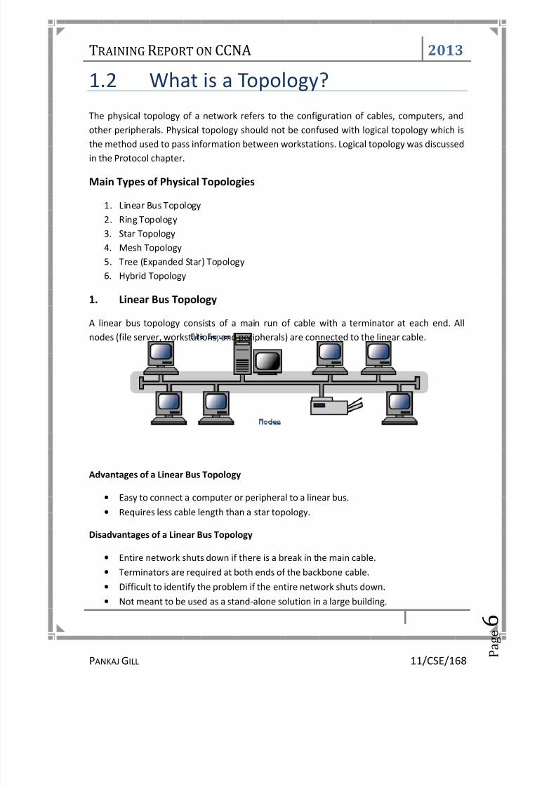
1. Linear Bus Topology
A linear bus topology consists of a main run of cable with a terminator at each end. Allnodes (file server, workstations, and peripherals) are connected to the linear cable.
Advantages of a Linear Bus Topology
• Easy to connect a computer or peripheral to a linear bus.• Requires less cable length than a star topology.
Disadvantages of a Linear Bus Topology
• Entire network shuts down if there is a break in the main cable.• Terminators are required at both ends of the backbone cable.• Difficult to identify the problem if the entire network shuts down.• Not meant to be used as a stand-alone solution in a large building.

8/13/2019 Training Report on CCNA(Cisco Certified Network Associate)
http://slidepdf.com/reader/full/training-report-on-ccnacisco-certified-network-associate 12/94
TRAINING REPORT ON CCNA 2013
PANKAJGILL 11/CSE/168 P
a g e 7
2. Ring Topology
Alternatively referred to as a ring network, the ring topology is a computer networkconfiguration where each network computer and devices are connected to each other
forming a large circle (or similar shape). Each packet is sent around the ring until it reachesits final destination. Today, the ring topology is seldom used. Below is a visual example of asimple computer setup on a network using a ring topology.
Advantages of Ring Topology
• This type of network topology is very organized. Each node gets to send the datawhen it receives an empty token. This helps to reduces chances of collision. Also inring topology all the traffic flows in only one direction at very high speed.
• Even when the load on the network increases, its performance is better than thatof Bus topology.
• There is no need for network server to control the connectivity betweenworkstations.
• Additional components do not affect the performance of network.• Each computer has equal access to resources.
Disadvantages of Ring Topology
• Each packet of data must pass through all the computers between source anddestination. This makes it slower than Star topology.
• If one workstation or port goes down, the entire network gets affected.• Network is highly dependent on the wire which connects different components.• MAU’s and network cards are expensive as compared to Ethernet cards and hubs.
3. Star Topology
A star topology is designed with each node (file server, workstations, and peripherals)connected directly to a central network hub, switch, or concentrator.

8/13/2019 Training Report on CCNA(Cisco Certified Network Associate)
http://slidepdf.com/reader/full/training-report-on-ccnacisco-certified-network-associate 13/94
TRAINING REPORT ON CCNA 2013
PANKAJGILL 11/CSE/168 P
a g e 8
Data on a star network passes through the hub, switch, or concentrator before continuing toits destination. The hub, switch, or concentrator manages and controls all functions of thenetwork. It also acts as a repeater for the data flow. This configuration is common withtwisted pair cable; however, it can also be used with coaxial cable or fiber optic cable.
Advantages of a Star Topology
• Easy to install and wire.• No disruptions to the network when connecting or removing devices.• Easy to detect faults and to remove parts.
Disadvantages of a Star Topology
• Requires more cable length than a linear topology.• If the hub, switch, or concentrator fails, nodes attached are disabled.• More expensive than linear bus topologies because of the cost of the hubs, etc.
4. Mesh Topology
A network setup where each computer and network device is interconnected with oneanother, allowing for most transmissions to be distributed, even if one of the connectionsgoes down. This topology is not commonly used for most computer networks as it is difficultand expensive to have redundant connection to every computer. However, this topology iscommonly used for wireless networks. Below is a visual example of a simple computer setupon a network using a mesh topology.

8/13/2019 Training Report on CCNA(Cisco Certified Network Associate)
http://slidepdf.com/reader/full/training-report-on-ccnacisco-certified-network-associate 14/94
TRAINING REPORT ON CCNA 2013
PANKAJGILL 11/CSE/168 P
a g e 9
Advantages of Mesh topology
• Data can be transmitted from different devices simultaneously. This topology canwithstand high traffic.
• Even if one of the components fails there is always an alternative present. So datatransfer doesn’t get affected.
• Expansion and modification in topology can be done without disrupting other nodes.
Disadvantages of Mesh topology
• There are high chances of redundancy in many of the network connections.• Overall cost of this network is way too high as compared to other network
topologies.• Set-up and maintenance of this topology is very difficult. Even administration of the
network is tough.
5. Tree or Expanded Star
A tree topology combines characteristics of linear bus and star topologies. It consists of groups of star-configured workstations connected to a linear bus backbone cable. Tree
topologies allow for the expansion of an existing network, and enable schools to configure anetwork to meet their needs.

8/13/2019 Training Report on CCNA(Cisco Certified Network Associate)
http://slidepdf.com/reader/full/training-report-on-ccnacisco-certified-network-associate 15/94
TRAINING REPORT ON CCNA 2013
PANKAJGILL 11/CSE/168 P
a g e 1
0
Advantages of a Tree Topology
• Point-to-point wiring for individual segments.• Supported by several hardware and software venders.
Disadvantages of a Tree Topology
• Overall length of each segment is limited by the type of cabling used.• If the backbone line breaks, the entire segment goes down.• More difficult to configure and wire than other topologies.
6. Hybrid Topology
In this type of topology we integrate two or more different topologies to form a resultanttopology which has good points (as well as weaknesses) of all the constituent basictopologies rather than having characteristics of one specific topology. This combination of topologies is done according to the requirements of the organization.
For example, if there exists a ring topology in one office department while a bus topology inanother department, connecting these two will result in Hybrid topology. Rememberconnecting two similar topologies cannot be termed as Hybrid topology. Star-Ring and Star-Bus networks are most common examples of hybrid network.
Let's see the benefits and drawbacks of this networking architecture

8/13/2019 Training Report on CCNA(Cisco Certified Network Associate)
http://slidepdf.com/reader/full/training-report-on-ccnacisco-certified-network-associate 16/94
TRAINING REPORT ON CCNA 2013
PANKAJGILL 11/CSE/168 P
a g e 1
1
Advantages of Hybrid Network Topology
• Reliable : Unlike other networks, fault detection and troubleshooting is easy inthis type of topology. The part in which fault is detected can be isolated from therest of network and required corrective measures can be taken, WITHOUT affectingthe functioning of rest of the network.
• Scalable : It’s easy to increase the size of network by adding new components,without disturbing existing architecture.
• Flexible : Hybrid Network can be designed according to the requirements of theorganization and by optimizing the available resources. Special care can be given tonodes where traffic is high as well as where chances of fault are high.
• Effective : Hybrid topology is the combination of two or more topologies, so wecan design it in such a way that strengths of constituent topologies are maximizedwhile there weaknesses are neutralized. For example we saw Ring Topology hasgood data reliability (achieved by use of tokens) and Star topology has high tolerancecapability (as each node is not directly connected to other but through centraldevice), so these two can be used effectively in hybrid star-ring topology.
Disadvantages of Hybrid Topology
• Complexity of Design: One of the biggest drawbacks of hybrid topology is its design.It’s not easy to design this type of architecture and it’s a tough job for designers.Configuration and installation process needs to be very efficient.
• Costly Hub: The hubs used to connect two distinct networks, are very expensive.These hubs are different from usual hubs as they need to be intelligent enough towork with different architectures and should be function even if a part of network is
down.
8/13/2019 Training Report on CCNA(Cisco Certified Network Associate)
http://slidepdf.com/reader/full/training-report-on-ccnacisco-certified-network-associate 17/94
TRAINING REPORT ON CCNA 2013
PANKAJGILL 11/CSE/168 P
a g e 1
2
• Costly Infrastructure: As hybrid architectures are usually larger in scale, they requirea lot of cables; cooling systems, sophisticate network devices, etc.
Considerations When Choosing a Topology
1. Money: A linear bus network may be the least expensive way to installa network; you do not have to purchase concentrators.
2. Length: Length of cable needed. The linear bus network uses shorterlengths of cable.
3. Future growth: With a star topology, expanding a network is easily done byadding another concentrator.
4. Cable type: The most common cable in schools is unshielded twisted pair, which ismost often used with star topologies.
Summary Chart
PhysicalTopology
Common Cable CommonProtocol
Linear Bus Twisted Pair or Coaxial Fiber EthernetStar Twisted Pair or Fiber EthernetTree Twisted Pair or Coaxial Fiber Ethernet
Collisions
Ethernet is a shared media, so there are rules for sending packets of data to avoid conflictsand protect data integrity. Nodes determine when the network is available for sendingpackets. It is possible that two nodes at different locations attempt to send data at the sametime. When both PCs are transferring a packet to the network at the same time, a collisionwill result.
8/13/2019 Training Report on CCNA(Cisco Certified Network Associate)
http://slidepdf.com/reader/full/training-report-on-ccnacisco-certified-network-associate 18/94
TRAINING REPORT ON CCNA 2013
PANKAJGILL 11/CSE/168 P
a g e 1
3
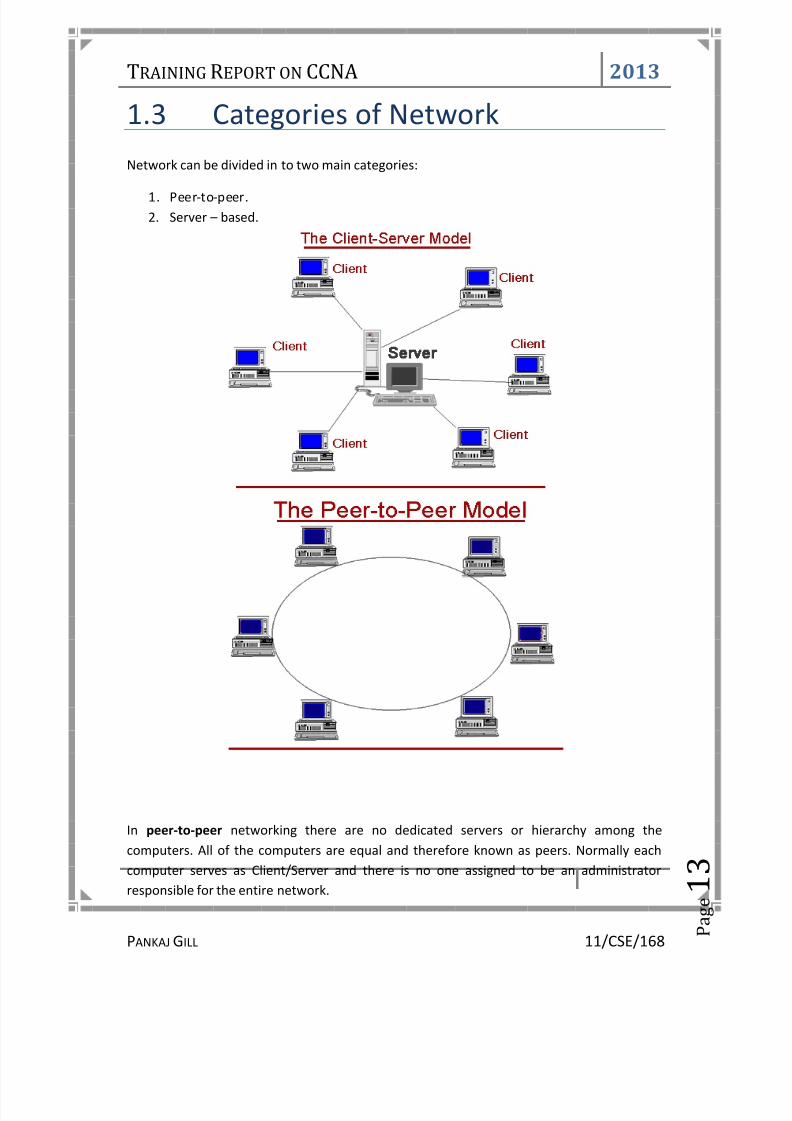
1.3 Categories of NetworkNetwork can be divided in to two main categories:
1. Peer-to-peer.2. Server – based.
In peer-to-peer networking there are no dedicated servers or hierarchy among thecomputers. All of the computers are equal and therefore known as peers. Normally eachcomputer serves as Client/Server and there is no one assigned to be an administrator
responsible for the entire network.

8/13/2019 Training Report on CCNA(Cisco Certified Network Associate)
http://slidepdf.com/reader/full/training-report-on-ccnacisco-certified-network-associate 19/94
TRAINING REPORT ON CCNA 2013
PANKAJGILL 11/CSE/168 P
a g e 1
4
Peer-to-peer networks are good choices for needs of small organizations where the usersare allocated in the same general area, security is not an issue and the organization and thenetwork will have limited growth within the foreseeable future.
The term Client/server refers to the concept of sharing the work involved in processing databetween the client computer and the most powerful server computer.
The client/server network is the most efficient way to provide:
• Databases and management of applications such as Spreadsheets, Accounting,Communications and Document management.
• Network management.• Centralized file storage.
The client/server model is basically an implementation of distributed or cooperativeprocessing. At the heart of the model is the concept of splitting application functionsbetween a client and a server processor. The division of labor between the differentprocessors enables the application designer to place an application function on theprocessor that is most appropriate for that function. This lets the software designeroptimize the use of processors--providing the greatest possible return on investment for thehardware.
Client/server application design also lets the application provider mask the actual location of
application function. The user often does not know where a specific operation is executing.The entire function may execute in either the PC or server, or the function may be splitbetween them. This masking of application function locations enables system implementersto upgrade portions of a system over time with a minimum disruption of applicationoperations, while protecting the investment in existing hardware and software.
The OSI Model:
Open System Interconnection (OSI) reference model has become an International standardand serves as a guide for networking. This model is the best known and most widely usedguide to describe networking environments. Vendors design network products based on thespecifications of the OSI model. It provides a description of how network hardware andsoftware work together in a layered fashion to make communications possible. It also helpswith trouble shooting by providing a frame of reference that describes how components aresupposed to function.

8/13/2019 Training Report on CCNA(Cisco Certified Network Associate)
http://slidepdf.com/reader/full/training-report-on-ccnacisco-certified-network-associate 20/94
TRAINING REPORT ON CCNA 2013
PANKAJGILL 11/CSE/168 P
a g e 1
5
There are seven to get familiar with and these are the physical layer, data link layer,network layer, transport layer, session layer, presentation layer, and the application layer.
1. Physical Layer , is just that the physical parts of the network such as wires, cables,and there media along with the length. Also this layer takes note of the electrical
signals that transmit data throughout system.2. Data Link Layer , this layer is where we actually assign meaning to the electrical
signals in the network. The layer also determines the size and format of data sent toprinters, and other devices. Also I don't want to forget that these are also callednodes in the network.
3. Network Layer , this layer provides the definition for the connection of two dissimilarnetworks.
4. Transport Layer , this layer allows data to be broken into smaller packages for data tobe distributed and addressed to other nodes (workstations).
5. Session Layer , this layer helps out with the task to carry information from one node(workstation) to another node (workstation). A session has to be made before wecan transport information to another computer.
6. Presentation Layer , this layer is responsible to code and decode data sent to thenode.
7. Application Layer , this layer allows you to use an application that will communicatewith say the operation system of a server. A good example would be using your webbrowser to interact with the operating system on a server such as Windows NT,which in turn gets the data you requested.

8/13/2019 Training Report on CCNA(Cisco Certified Network Associate)
http://slidepdf.com/reader/full/training-report-on-ccnacisco-certified-network-associate 21/94
TRAINING REPORT ON CCNA 2013
PANKAJGILL 11/CSE/168 P
a g e 1
6
1.4 Network Architectures1. Ethernet
Ethernet is the most popular physical layer LAN technology in use today. Other LAN typesinclude Token Ring, Fast Ethernet, Fiber Distributed Data Interface (FDDI), AsynchronousTransfer Mode (ATM) and LocalTalk. Ethernet is popular because it strikes a good balancebetween speed, cost and ease of installation. These benefits, combined with wideacceptance in the computer marketplace and the ability to support virtually all popularnetwork protocols, make Ethernet an ideal networking technology for most computer userstoday. The Institute for Electrical and Electronic Engineers (IEEE) defines the Ethernetstandard as IEEE Standard 802.3. This standard defines rules for configuring an Ethernet
network as well as specifying how elements in an Ethernet network interact with oneanother. By adhering to the IEEE standard, network equipment and network protocols cancommunicate efficiently.
2. Fast Ethernet
For Ethernet networks that need higher transmission speeds, the Fast Ethernet standard(IEEE 802.3u) has been established. This standard raises the Ethernet speed limit from 10Megabits per second (Mbps) to 100 Mbps with only minimal changes to the existing cablestructure. There are three types of Fast Ethernet: 100BASE-TX for use with level 5 UTP cable,100BASE-FX for use with fiber-optic cable, and 100BASE-T4 which utilizes an extra two wiresfor use with level 3 UTP cable. The 100BASE-TX standard has become the most popular dueto its close compatibility with the 10BASE-T Ethernet standard. For the network manager,the incorporation of Fast Ethernet into an existing configuration presents a host of decisions. Managers must determine the number of users in each site on the network thatneed the higher throughput, decide which segments of the backbone need to bereconfigured specifically for 100BASE-T and then choose the necessary hardware to connectthe 100BASE-T segments with existing 10BASE-T segments. Gigabit Ethernet is a futuretechnology that promises a migration path beyond Fast Ethernet so the next generation of networks will support even higher data transfer speeds.

8/13/2019 Training Report on CCNA(Cisco Certified Network Associate)
http://slidepdf.com/reader/full/training-report-on-ccnacisco-certified-network-associate 22/94
TRAINING REPORT ON CCNA 2013
PANKAJGILL 11/CSE/168 P
a g e 1
7
3. Token Ring
Token Ring is another form of network configuration which differs from Ethernet in that allmessages are transferred in a unidirectional manner along the ring at all times. Data istransmitted in tokens, which are passed along the ring and viewed by each device. When adevice sees a message addressed to it, that device copies the message and then marks thatmessage as being read. As the message makes its way along the ring, it eventually gets backto the sender who now notes that the message was received by the intended device. Thesender can then remove the message and free that token for use by others.
Various PC vendors have been proponents of Token Ring networks at different times andthus these types of networks have been implemented in many organizations.
4. FDDI
FDDI (Fiber-Distributed Data Interface) is a standard for data transmission on fiber opticlines in a local area network that can extend in range up to 200 km (124 miles). The FDDIprotocol is based on the token ring protocol. In addition to being large geographically, anFDDI local area network can support thousands of users.

8/13/2019 Training Report on CCNA(Cisco Certified Network Associate)
http://slidepdf.com/reader/full/training-report-on-ccnacisco-certified-network-associate 23/94
TRAINING REPORT ON CCNA 2013
PANKAJGILL 11/CSE/168 P
a g e 1
8
1.5 ProtocolsNetwork protocols are standards that allow computers to communicate. A protocol defineshow computers identify one another on a network, the form that the data should take intransit, and how this information is processed once it reaches its final destination. Protocolsalso define procedures for handling lost or damaged transmissions or "packets." TCP/IP (forUNIX, Windows NT, Windows 95 and other platforms), IPX (for Novell NetWare), DECnet (fornetworking Digital Equipment Corp. computers), AppleTalk (for Macintosh computers), andNetBIOS/NetBEUI (for LAN Manager and Windows NT networks) are the main types of network protocols in use today.
Although each network protocol is different, they all share the same physical cabling. This
common method of accessing the physical network allows multiple protocols to peacefullycoexist over the network media, and allows the builder of a network to use commonhardware for a variety of protocols. This concept is known as "protocol independence,"
Some Important Protocols and their job:
Protocol Acronym Its JobTransmission ControlProtocol/internet Protocol
TCP/IP The backbone protocol of the internet.Popular also for intranets using the internet
Internetwork Package
Exchange/Sequenced PacketExchange
IPX/SPX This is a standard protocol for Novell
Network Operating System
NetBIOS Extended User Interface NetBEUI This is a Microsoft protocol that doesn'tsupport routing to other networks
File Transfer Protocol FTP Used to send and receive files from aremote host
Hyper Text Transfer Protocol HTTP Used for the web to send documents that isencoded in HTML.
Secured Hyper Text TransferProtocol
HTTPS Information transfer is encrypted andsecured to encrypted information.
Network File Services NFS Allows network nodes or workstations toaccess files and drives as if they were theirown.
Simple Mail Transfer Protocol SMTP Used to send Email over a networkTelnet Used to connect to a host and emulate a
terminal that the remote server canrecognize
Post Office Protocol POP This protocol is used for transferring ordownloading mails to your local system. So,
that you can view/compose mails offline.Internet Message Access Protocol IMAP4 This is secured version of POP.

8/13/2019 Training Report on CCNA(Cisco Certified Network Associate)
http://slidepdf.com/reader/full/training-report-on-ccnacisco-certified-network-associate 24/94
TRAINING REPORT ON CCNA 2013
PANKAJGILL 11/CSE/168 P
a g e 1
9
Routing Information Protocol RIP It is a protocol that is used to communicateb/w multiple routers for data transmissionat a long distance.
Dynamic Host Configuration
Protocol
DHCP This protocol is used for assignment of
dynamic IP address to the host systems.
Introduction to TCP/IP Networks:
TCP/IP-based networks play an increasingly important role in computer networks. Perhapsone reason for their appeal is that they are based on an open specification that is notcontrolled by any vendor.
What Is TCP/IP?TCP stands for Transmission Control Protocol and IP stands for Internet Protocol. The termTCP/IP is not limited just to these two protocols, however. Frequently, the term TCP/IP isused to refer to a group of protocols related to the TCP and IP protocols such as the UserDatagram Protocol (UDP), File Transfer Protocol (FTP), Terminal Emulation Protocol(TELNET), and so on.
The Origins of TCP/IP
In the late 1960s, DARPA (the Defense Advanced Research Project Agency), in the UnitedStates, noticed that there was a rapid proliferation of computers in militarycommunications. Computers, because they can be easily programmed, provide flexibility inachieving network functions that is not available with other types of communicationsequipment. The computers then used in military communications were manufactured bydifferent vendors and were designed to interoperate with computers from that vendor only.Vendors used proprietary protocols in their communications equipment. The military had amulti vendor network but no common protocol to support the heterogeneous equipmentfrom different vendors

8/13/2019 Training Report on CCNA(Cisco Certified Network Associate)
http://slidepdf.com/reader/full/training-report-on-ccnacisco-certified-network-associate 25/94
TRAINING REPORT ON CCNA 2013
PANKAJGILL 11/CSE/168 P
a g e 2
0
1.6 Transmission MediaTransmission Media is of two types:
1. Wired2. Wireless
1. Wired Transmission
Cable is the medium through which information usually moves from one network device toanother. There are several types of cable which are commonly used with LANs. In somecases, a network will utilize only one type of cable, other networks will use a variety of cabletypes. The type of cable chosen for a network is related to the network's topology, protocol,and size. Understanding the characteristics of different types of cable and how they relateto other aspects of a network is necessary for the development of a successful network.
The following are the wired mediums:
• Unshielded Twisted Pair (UTP) Cable• Shielded Twisted Pair (STP) Cable• Coaxial Cable• Fiber Optic Cable
Twisted pair cabling comes in two varieties: shielded and unshielded. Unshielded twistedpair (UTP) is the most popular and is generally the best option for school networks.

8/13/2019 Training Report on CCNA(Cisco Certified Network Associate)
http://slidepdf.com/reader/full/training-report-on-ccnacisco-certified-network-associate 26/94
TRAINING REPORT ON CCNA 2013
PANKAJGILL 11/CSE/168 P
a g e 2
1
The quality of UTP may vary from telephone-grade wire to extremely high-speed cable. Thecable has four pairs of wires inside the jacket. Each pair is twisted with a different number of twists per inch to help eliminate interference from adjacent pairs and other electricaldevices. The tighter the twisting, the higher the supported transmission rate and the greaterthe cost per foot. The EIA/TIA (Electronic Industry Association/Telecommunication IndustryAssociation) has established standards of UTP and rated six categories of wire (additionalcategories are emerging).
Categories of Unshielded Twisted Pair
Category Speed Use1 1 Mbps Voice Only (Telephone Wire)2 4 Mbps LocalTalk & Telephone (Rarely used)3 16 Mbps 10BaseT Ethernet4 20 Mbps Token Ring (Rarely used)5 100 Mbps (2 pair) 100BaseT Ethernet
1000 Mbps (4 pair) Gigabit Ethernet5e 1,000 Mbps Gigabit Ethernet6 10,000 Mbps Gigabit Ethernet
Unshielded Twisted Pair Cabling Standards
• Cat 1 : Currently unrecognized by TIA/EIA. Previously used for POTS
telephone communications, ISDN and doorbell wiring.• Cat 2 : Currently unrecognized by TIA/EIA. Previously was frequently used on
4 Mbit/s token ring networks.• Cat 3 : Currently defined in TIA/EIA-568-B; used for data networks utilizing
frequencies up to 16MHz. Historically popular for 10 Mbit/s Ethernet networks.• Cat 4 : Currently unrecognized by TIA/EIA. Provided performance of up to 20
MHz, and was frequently used on 16 Mbit/s token ring networks.• Cat 5 : Currently unrecognized by TIA/EIA. Provided performance of up to
100 MHz, and was frequently used on 100 Mbit/s Ethernet networks. May beunsuitable for 1000BASE-T gigabit Ethernet.
• Cat 5e : Currently defined in TIA/EIA-568-B. Provides performance of up to100 MHz, and is frequently used for both 100 Mbit/s and gigabit Ethernet networks.
• Cat 6 : Currently defined in TIA/EIA-568-B. Provides performance of up to250 MHz, more than double category 5 and 5e.
• Cat 6a : Future specification for 10 Gbit/s applications.• Cat 7 : An informal name applied to ISO/IEC 11801 Class F cabling. This
standard specifies four individually-shielded pairs (STP) inside an overall shield.
Designed for transmission at frequencies up to 600 MHz’s.

8/13/2019 Training Report on CCNA(Cisco Certified Network Associate)
http://slidepdf.com/reader/full/training-report-on-ccnacisco-certified-network-associate 27/94
TRAINING REPORT ON CCNA 2013
PANKAJGILL 11/CSE/168 P
a g e 2
2
1. Unshielded Twisted Pair Connector
The standard connector for unshielded twisted pair cabling is an RJ-45 connector. This is aplastic connector that looks like a large telephone-style connector. A slot allows the RJ-45 to
be inserted only one way. RJ stands for Registered Jack, implying that the connector followsa standard borrowed from the telephone industry. This standard designates which wire goeswith each pin inside the connector.
RJ-45 connector
2. Shielded Twisted Pair (STP) Cable
Although UTP cable is the least expensive cable, it may be susceptible to radio and electricalfrequency interference (it should not be too close to electric motors, fluorescent lights,etc.). If you must place cable in environments with lots of potential interference, or if youmust place cable in extremely sensitive environments that may be susceptible to theelectrical current in the UTP, shielded twisted pair may be the solution. Shielded cables canalso help to extend the maximum distance of the cables.
• Shielded twisted pair cable is available in three different configurations:• Each pair of wires is individually shielded with foil.• There is a foil or braid shield inside the jacket covering all wires (as a group).
There is a shield around each individual pair, as well as around the entire group of wires
(referred to as double shield twisted pair).
3. Coaxial Cable
Coaxial cabling has a single copper conductor at its center. A plastic layer provides insulationbetween the center conductor and a braided metal shield. The metal shield helps to blockany outside interference from fluorescent lights, motors, and other computers.
Coaxial cable

8/13/2019 Training Report on CCNA(Cisco Certified Network Associate)
http://slidepdf.com/reader/full/training-report-on-ccnacisco-certified-network-associate 28/94
TRAINING REPORT ON CCNA 2013
PANKAJGILL 11/CSE/168 P
a g e 2
3
Although coaxial cabling is difficult to install, it is highly resistant to signal interference. Inaddition, it can support greater cable lengths between network devices than twisted paircable. The two types of coaxial cabling are thick coaxial and thin coaxial .
Thin coaxial cable is also referred to as thinnet. 10Base2 refers to the specifications for thincoaxial cable carrying Ethernet signals. The 2 refers to the approximate maximum segmentlength being 200 meters. In actual fact the maximum segment length is 185 meters. Thincoaxial cable has been popular in school networks, especially linear bus networks.
Thick coaxial cable is also referred to as thicknet. 10Base5 refers to the specifications forthick coaxial cable carrying Ethernet signals. The 5 refers to the maximum segment lengthbeing 500 meters. Thick coaxial cable has an extra protective plastic cover that helps keepmoisture away from the center conductor. This makes thick coaxial a great choice whenrunning longer lengths in a linear bus network. One disadvantage of thick coaxial is that itdoes not bend easily and is difficult to install.
Coaxial Cable Connectors
The most common type of connector used with coaxial cables is the Bayone-Neill-Concelman (BNC) connector. Different types of adapters are available for BNC connectors,including a T-connector, barrel connector, and terminator. Connectors on the cable are theweakest points in any network. To help avoid problems with your network, always use theBNC connectors that crimp, rather screw, onto the cable.
BNC connector
4. Fiber Optic Cable
Fiber optic cabling consists of a center glass core surrounded by several layers of protectivematerials. It transmits light rather than electronic signals eliminating the problem of electrical interference. This makes it ideal for certain environments that contain a largeamount of electrical interference. It has also made it the standard for connecting networksbetween buildings, due to its immunity to the effects of moisture and lighting.
Fiber optic cable has the ability to transmit signals over much longer distances than coaxialand twisted pair. It also has the capability to carry information at vastly greater speeds. Thiscapacity broadens communication possibilities to include services such as videoconferencing and interactive services. The cost of fiber optic cabling is comparable to copper

8/13/2019 Training Report on CCNA(Cisco Certified Network Associate)
http://slidepdf.com/reader/full/training-report-on-ccnacisco-certified-network-associate 29/94
TRAINING REPORT ON CCNA 2013
PANKAJGILL 11/CSE/168 P
a g e 2
4
cabling; however, it is more difficult to install and modify. 10BaseF refers to thespecifications for fiber optic cable carrying Ethernet signals.
The center core of fiber cables is made from glass or plastic fibers (see fig 5). A plastic
coating then cushions the fiber center, and kevlar fibers help to strengthen the cables andprevent breakage. The outer insulating jacket made of teflon or PVC.
Fiber optic cable
There are two common types of fiber cables -- single mode and multimode. Multimode
cable has a larger diameter; however, both cables provide high bandwidth at high speeds.Single mode can provide more distance, but it is more expensive.
Specification Cable Type10BaseT Unshielded Twisted Pair10Base2 Thin Coaxial10Base5 Thick Coaxial100BaseT Unshielded Twisted Pair100BaseFX Fiber Optic100BaseBX Single mode Fiber
100BaseSX Multimode Fiber1000BaseT Unshielded Twisted Pair1000BaseFX Fiber Optic1000BaseBX Single mode Fiber1000BaseSX Multimode Fiber
Installing Cable - Some Guidelines
When running cable, it is best to follow a few simple rules:
1. Always use more cable than you need. Leave plenty of slack.2. Test every part of a network as you install it. Even if it is brand new, it may have
problems that will be difficult to isolate later.3. Stay at least 3 feet away from fluorescent light boxes and other sources of electrical
interference.4. If it is necessary to run cable across the floor, cover the cable with cable protectors.5. Label both ends of each cable.6. Use cable ties (not tape) to keep cables in the same location together.

8/13/2019 Training Report on CCNA(Cisco Certified Network Associate)
http://slidepdf.com/reader/full/training-report-on-ccnacisco-certified-network-associate 30/94
TRAINING REPORT ON CCNA 2013
PANKAJGILL 11/CSE/168 P
a g e 2
5
Ethernet Cable Connectors
• 8P8C - 8 positions, 8 conductor modular connector. Incorrectly referred to as RJ45.• Cables available assembled, or connectors may be crimped on cable.
There are two types of Ethernet Cables:
1. Straight Cable : To connect different kinds of devices. Eg, Switch to System,2. Cross Cable : To connect similar kinds of devices. Eg, System to System
Ethernet RJ45 Pin Configurations
T568B RJ45 Connection
• Eight connections consist of four wire pairs.• Pairs are solid and stripe of same color.• Two pin configurations, T568A and T568B, which are interoperable.

8/13/2019 Training Report on CCNA(Cisco Certified Network Associate)
http://slidepdf.com/reader/full/training-report-on-ccnacisco-certified-network-associate 31/94

8/13/2019 Training Report on CCNA(Cisco Certified Network Associate)
http://slidepdf.com/reader/full/training-report-on-ccnacisco-certified-network-associate 32/94
TRAINING REPORT ON CCNA 2013
PANKAJGILL 11/CSE/168 P
a g e 2
7
set to the appropriate speed. Full duplex networking is another option, where a dedicatedconnection to a switch allows a NIC to operate at twice the speed.
Hubs/Repeaters
Hubs/repeaters are used to connect together two or more Ethernet segments of any mediatype. In larger designs, signal quality begins to deteriorate as segments exceed theirmaximum length. Hubs provide the signal amplification required to allow a segment to beextended a greater distance. A hub takes any incoming signal and repeats it out all ports.
Ethernet hubs are necessary in star topologies such as 10BASE-T. A multi-port twisted pairhub allows several point-to-point segments to be joined into one network. One end of thepoint-to-point link is attached to the hub and the other is attached to the computer. If thehub is attached to a backbone, then all computers at the end of the twisted pair segmentscan communicate with all the hosts on the backbone. The number and type of hubs in anyone-collision domain is limited by the Ethernet rules. These repeater rules are discussed inmore detail later.
Network Type Max NodesPer Segment
Max DistancePer Segment
10BASE-T10BASE210BASE5
10BASE-FL
230100
2
100m185m500m
2000m
Adding Speed
While repeaters allow LANs to extend beyond normal distance limitations, they still limit thenumber of nodes that can be supported. Bridges and switches, however, allow LANs to growsignificantly larger by virtue of their ability to support full Ethernet segments on each port.Additionally, bridges and switches selectively filter network traffic to only those packetsneeded on each segment - this significantly increases throughput on each segment and onthe overall network. By providing better performance and more flexibility for networktopologies, bridges and switches will continue to gain popularity among network managers.
Bridges
The function of a bridge is to connect separate networks together. Bridges connect differentnetworks types (such as Ethernet and Fast Ethernet) or networks of the same type. Bridgesmap the Ethernet addresses of the nodes residing on each network segment and allow onlynecessary traffic to pass through the bridge. When a packet is received by the bridge, the
bridge determines the destination and source segments. If the segments are the same, thepacket is dropped ("filtered"); if the segments are different, then the packet is "forwarded"

8/13/2019 Training Report on CCNA(Cisco Certified Network Associate)
http://slidepdf.com/reader/full/training-report-on-ccnacisco-certified-network-associate 33/94
TRAINING REPORT ON CCNA 2013
PANKAJGILL 11/CSE/168 P
a g e 2
8
to the correct segment. Additionally, bridges do not forward bad or misaligned packets.Bridges are also called "store-and-forward" devices because they look at the whole Ethernetpacket before making filtering or forwarding decisions. Filtering packets and regeneratingforwarded packets enable bridging technology to split a network into separate collisiondomains. This allows for greater distances and more repeaters to be used in the totalnetwork design.
Ethernet Switches
Ethernet switches are an expansion of the concept in Ethernet bridging. LAN switches canlink four, six, ten or more networks together, and have two basic architectures: cut-throughand store-and-forward. In the past, cut-through switches were faster because theyexamined the packet destination address only before forwarding it on to its destination
segment. A store-and-forward switch, on the other hand, accepts and analyzes the entirepacket before forwarding it to its destination.
It takes more time to examine the entire packet, but it allows the switch to catch certainpacket errors and keep them from propagating through the network. Both cut-through andstore-and-forward switches separate a network into collision domains, allowing networkdesign rules to be extended. Each of the segments attached to an Ethernet switch has a full10 Mbps of bandwidth shared by fewer users, which results in better performance (asopposed to hubs that only allow bandwidth sharing from a single Ethernet). Newer switchestoday offer high-speed links, FDDI, Fast Ethernet or ATM. These are used to link switchestogether or give added bandwidth to high-traffic servers. A network composed of a numberof switches linked together via uplinks is termed a "collapsed backbone" network.
Routers
Routers filter out network traffic by specific protocol rather than by packet address. Routersalso divide networks logically instead of physically. An IP router can divide a network intovarious subnets so that only traffic destined for particular IP addresses can pass betweensegments. Network speed often decreases due to this type of intelligent forwarding. Such
filtering takes more time than that exercised in a switch or bridge, which only looks at theEthernet address. However, in more complex networks, overall efficiency is improved byusing routers.
What is a Network Firewall?
A firewall is a system or group of systems that enforces an access control policy betweentwo networks. The actual means by which this is accomplished varies widely, but inprinciple, the firewall can be thought of as a pair of mechanisms: one which exists to blocktraffic, and the other which exists to permit traffic. Some firewalls place a greater emphasison blocking traffic, while others emphasize permitting traffic. Probably the most important

8/13/2019 Training Report on CCNA(Cisco Certified Network Associate)
http://slidepdf.com/reader/full/training-report-on-ccnacisco-certified-network-associate 34/94
TRAINING REPORT ON CCNA 2013
PANKAJGILL 11/CSE/168 P
a g e 2
9
thing to recognize about a firewall is that it implements an access control policy. If you don'thave a good idea of what kind of access you want to allow or to deny, a firewall really won'thelp you. It's also important to recognize that the firewall's configuration, because it is amechanism for enforcing policy, imposes its policy on everything behind it. Administratorsfor firewalls managing the connectivity for a large number of hosts therefore have a heavyresponsibility.
Network Design Criteria
Ethernets and Fast Ethernets have design rules that must be followed in order to functioncorrectly. Maximum number of nodes, number of repeaters and maximum segmentdistances are defined by the electrical and mechanical design properties of each type of Ethernet and Fast Ethernet media.
A network using repeaters, for instance, functions with the timing constraints of Ethernet.Although electrical signals on the Ethernet media travel near the speed of light, it still takesa finite time for the signal to travel from one end of a large Ethernet to another. TheEthernet standard assumes it will take roughly 50 microseconds for a signal to reach itsdestination.
Ethernet is subject to the "5-4-3" rule of repeater placement: The network can only havefive segments connected; it can only use four repeaters; and of the five segments, onlythree can have users attached to them; the other two must be inter-repeater links.
If the design of the network violates these repeater and placement rules, then timingguidelines will not be met and the sending station will resend that packet. This can lead tolost packets and excessive resent packets, which can slow network performance and createtrouble for applications. Fast Ethernet has modified repeater rules, since the minimumpacket size takes less time to transmit than regular Ethernet. The length of the network linksallows for a fewer number of repeaters. In Fast Ethernet networks, there are two classes of repeaters. Class I repeaters have a latency of 0.7 microseconds or less and are limited to onerepeater per network. Class II repeaters have a latency of 0.46 microseconds or less and are
limited to two repeaters per network. The following are the distance (diameter)characteristics for these types of Fast Ethernet repeater combinations:
Fast Ethernet Copper FiberNo RepeatersOne Class I RepeaterOne Class II RepeaterTwo Class II Repeaters
100m200m200m205m
412m*272m272m228m
* Full Duplex Mode 2 km
When conditions require greater distances or an increase in the number of nodes/repeaters,then a bridge, router or switch can be used to connect multiple networks together. These
8/13/2019 Training Report on CCNA(Cisco Certified Network Associate)
http://slidepdf.com/reader/full/training-report-on-ccnacisco-certified-network-associate 35/94
TRAINING REPORT ON CCNA 2013
PANKAJGILL 11/CSE/168 P
a g e 3
0
devices join two or more separate networks, allowing network design criteria to berestored. Switches allow network designers to build large networks that function well. Thereduction in costs of bridges and switches reduces the impact of repeater rules on networkdesign.
Each network connected via one of these devices is referred to as a separate collisiondomain in the overall network.
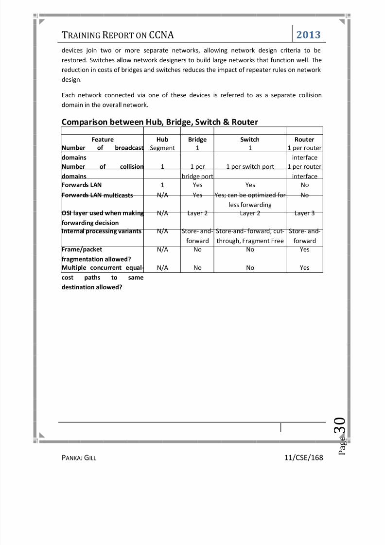
Comparison between Hub, Bridge, Switch & Router
Feature Hub Bridge Switch RouterNumber of broadcastdomains
Segment 1 1 1 per routerinterface
Number of collisiondomains
1 1 perbridge port
1 per switch port 1 per routerinterface
Forwards LAN 1 Yes Yes NoForwards LAN multicasts N/A Yes Yes; can be optimized for
less forwardingNo
OSI layer used when makingforwarding decision
N/A Layer 2 Layer 2 Layer 3
Internal processing variants N/A Store- and-forward
Store-and- forward, cut-through, Fragment Free
Store- and-forward
Frame/packet
fragmentation allowed?
N/A No No Yes
Multiple concurrent equal-cost paths to samedestination allowed?
N/A No No Yes

8/13/2019 Training Report on CCNA(Cisco Certified Network Associate)
http://slidepdf.com/reader/full/training-report-on-ccnacisco-certified-network-associate 36/94
TRAINING REPORT ON CCNA 2013
PANKAJGILL 11/CSE/168 P
a g e 3
1
1.8 Types of Servers
1. Device Servers
A device server is defined as a specialized, network-based hardware device designed toperform a single or specialized set of server functions. It is characterized by a minimaloperating architecture that requires no per seat network operating system license, andclient access that is independent of any operating system or proprietary protocol. Inaddition the device server is a "closed box," delivering extreme ease of installation, minimalmaintenance, and can be managed by the client remotely via a Web browser.
Print servers, terminal servers, remote access servers and network time servers are
examples of device servers which are specialized for particular functions. Each of thesetypes of servers has unique configuration attributes in hardware or software that help themto perform best in their particular arena.
2. Print Servers
Print servers allow printers to be shared by other users on the network. Supporting eitherparallel and/or serial interfaces, a print server accepts print jobs from any person on thenetwork using supported protocols and manages those jobs on each appropriate printer.
Print servers generally do not contain a large amount of memory; printers simply storeinformation in a queue. When the desired printer becomes available, they allow the host totransmit the data to the appropriate printer port on the server. The print server can thensimply queue and print each job in the order in which print requests are received, regardlessof protocol used or the size of the job.
3. Multiport Device Servers
Devices that are attached to a network through a multiport device server can be sharedbetween terminals and hosts at both the local site and throughout the network. A singleterminal may be connected to several hosts at the same time (in multiple concurrentsessions), and can switch between them. Multiport device servers are also used to networkdevices that have only serial outputs. A connection between serial ports on different serversis opened, allowing data to move between the two devices.
Given its natural translation ability, a multi-protocol multiport device server can performconversions between the protocols it knows, like LAT and TCP/IP. While server bandwidth isnot adequate for large file transfers, it can easily handle host-to-host inquiry/responseapplications, electronic mailbox checking, etc. And it is far more economical than the
alternatives of acquiring expensive host software and special-purpose converters. Multiport

8/13/2019 Training Report on CCNA(Cisco Certified Network Associate)
http://slidepdf.com/reader/full/training-report-on-ccnacisco-certified-network-associate 37/94
8/13/2019 Training Report on CCNA(Cisco Certified Network Associate)
http://slidepdf.com/reader/full/training-report-on-ccnacisco-certified-network-associate 38/94
TRAINING REPORT ON CCNA 2013
PANKAJGILL 11/CSE/168 P
a g e 3
3
1.9 IP AddressingAn IP (Internet Protocol) address is a unique identifier for a node or host connection on anIP network. An IP address is a 32 bit binary number usually represented as 4 decimal values,each representing 8 bits, in the range 0 to 255 (known as octets) separated by decimalpoints. This is known as "dotted decimal" notation.
Example: 140.179.220.200
It is sometimes useful to view the values in their binary form.
140 .179 .220 .200
10001100.10110011.11011100.11001000
Every IP address consists of two parts, one identifying the network and one identifying thenode. The Class of the address and the subnet mask determine which part belongs to thenetwork address and which part belongs to the node address.
Address Classes:
There are 5 different address classes. You can determine which class any IP address is in by
examining the first 4 bits of the IP address.
Class A addresses begin with 0xxx, or 1 to 126 decimal.
Class B addresses begin with 10xx, or 128 to 191 decimal, because 127 is loopback address.
Class C addresses begin with 110x, or 192 to 223 decimal.
Class D addresses begin with 1110, or 224 to 239 decimal.
Class E addresses begin with 1111, or 240 to 254 decimal.
Addresses beginning with 01111111, or 127 decimal, are reserved for loopback and forinternal testing on a local machine. [You can test this: you should always be able to ping127.0.0.1, which points to yourself] Class D addresses are reserved for multicasting. Class Eaddresses are reserved for future use. They should not be used for host addresses.
Now we can see how the Class determines, by default, which part of the IP address belongsto the network (N) and which part belongs to the node (n).

8/13/2019 Training Report on CCNA(Cisco Certified Network Associate)
http://slidepdf.com/reader/full/training-report-on-ccnacisco-certified-network-associate 39/94
TRAINING REPORT ON CCNA 2013
PANKAJGILL 11/CSE/168 P
a g e 3
4
Class A -- NNNNNNNN.nnnnnnnn.nnnnnnn.nnnnnnnClass B -- NNNNNNNN.NNNNNNNN.nnnnnnnn.nnnnnnnnClass C -- NNNNNNNN.NNNNNNNN.NNNNNNNN.nnnnnnnn
In the example, 140.179.220.200 is a Class B address so by default the Network part of theaddress (also known as the Network Address) is defined by the first two octets (140.179.x.x)and the node part is defined by the last 2 octets (x.x.220.200).
In order to specify the network address for a given IP address, the node section is set to all"0"s. In our example, 140.179.0.0 specifies the network address for 140.179.220.200. Whenthe node section is set to all "1"s, it specifies a broadcast that is sent to all hosts on thenetwork. 140.179.255.255 specifies the example broadcast address. Note that this is trueregardless of the length of the node section.
Private Subnets
There are three IP network addresses reserved for private networks. The addresses are10.0.0.0/8, 172.16.0.0/12, and 192.168.0.0/16. They can be used by anyone setting upinternal IP networks, such as a lab or home LAN behind a NAT or proxy server or a router. Itis always safe to use these because routers on the Internet will never forward packetscoming from these addresses.
Subnetting an IP Network can be done for a variety of reasons, including organization, use of
different physical media (such as Ethernet, FDDI, WAN, etc.), preservation of address space,and security. The most common reason is to control network traffic. In an Ethernet network,all nodes on a segment see all the packets transmitted by all the other nodes on thatsegment. Performance can be adversely affected under heavy traffic loads, due to collisionsand the resulting retransmissions. A router is used to connect IP networks to minimize theamount of traffic each segment must receive.
Subnet Masking
Applying a subnet mask to an IP address allows you to identify the network and node parts
of the address. The network bits are represented by the 1s in the mask, and the node bitsare represented by the 0s. Performing a bitwise logical AND operation between the IPaddress and the subnet mask results in the Network Address or Number.
For example, using our test IP address and the default Class B subnet mask, we get:
10001100.10110011.11110000.11001000 140.179.240.200 Class B IP Address11111111.11111111.00000000.00000000 255.255.000.000 Default Class B Subnet Mask10001100.10110011.00000000.00000000 140.179.000.000 Network Address
8/13/2019 Training Report on CCNA(Cisco Certified Network Associate)
http://slidepdf.com/reader/full/training-report-on-ccnacisco-certified-network-associate 40/94

8/13/2019 Training Report on CCNA(Cisco Certified Network Associate)
http://slidepdf.com/reader/full/training-report-on-ccnacisco-certified-network-associate 41/94
TRAINING REPORT ON CCNA 2013
PANKAJGILL 11/CSE/168 P
a g e 3
6
1.10 Examining your Network withCommands
1. PING
PING is used to check for a response from another computer on the network. It can tell youa great deal of information about the status of the network and the computers you arecommunicating with.Ping returns different responses depending on the computer inquestion. The responses are similar depending on the options used.
Ping uses IP to request a response from the host. It does not use TCP. It takes its name froma submarine sonar search - you send a short sound burst and listen for an echo - a ping -coming back.
In an IP network, `ping' sends a short data burst - a single packet - and listens for a singlepacket in reply. Since this tests the most basic function of an IP network (delivery of singlepacket), it's easy to see how you can learn a lot from some `pings'.
To stop ping, Press Ctrl+C. This terminates the program and prints out a nice summary of the number of packets transmitted, the number received, and the percentage of packetslost, plus the minimum, average, and maximum round-trip times of the packets.
Sample PING session

8/13/2019 Training Report on CCNA(Cisco Certified Network Associate)
http://slidepdf.com/reader/full/training-report-on-ccnacisco-certified-network-associate 42/94
TRAINING REPORT ON CCNA 2013
PANKAJGILL 11/CSE/168 P
a g e 3
7
The Time To Live (TTL) field can be interesting. The main purpose of this is so that a packetdoesn't live forever on the network and will eventually die when it is deemed "lost." But forus, it provides additional information. We can use the TTL to determine approximately howmany router hops the packet has gone through. In this case it's 255 minus N hops, where Nis the TTL of the returning Echo Replies. If the TTL field varies in successive pings, it couldindicate that the successive reply packets are going via different routes, which isn't a greatthing.
The time field is an indication of the round-trip time to get a packet to the remote host. Thereply is measured in milliseconds. In general, it's best if round-trip times are under 200milliseconds. The time it takes a packet to reach its destination is called latency. If you see alarge variance in the round-trip times (which is called "jitter"), you are going to see poorperformance talking to the host
2. NSLOOKUP
NSLOOKUP is an application that facilitates looking up hostnames on the network. It canreveal the IP address of a host or, using the IP address, return the host name.
It is very important when troubleshooting problems on a network that you can verify thecomponents of the networking process. Nslookup allows this by revealing details within theinfrastructure.
3. NETSTAT
NETSTAT is used to look up the various active connections within a computer. It is helpful tounderstand what computers or networks you are connected to. This allows you to furtherinvestigate problems. One host may be responding well but another may be less responsive.
4. IPconfig
This is a Microsoft windows NT, 2000 command. It is very useful in determining what couldbe wrong with a network. This command when used with the /all switch, reveal enormousamounts of troubleshooting information within the system.
Windows 2000 IP Configuration

8/13/2019 Training Report on CCNA(Cisco Certified Network Associate)
http://slidepdf.com/reader/full/training-report-on-ccnacisco-certified-network-associate 43/94

8/13/2019 Training Report on CCNA(Cisco Certified Network Associate)
http://slidepdf.com/reader/full/training-report-on-ccnacisco-certified-network-associate 44/94
TRAINING REPORT ON CCNA 2013
PANKAJGILL 11/CSE/168 P
a g e 3
9
CCNA T RAINING REPORT
2. DNS2.1 Introduction 402.2 Operations 43
2.3 DNS Server Installation 462.4 DNS Server Configuration 502.5 Managing DNS Records 542.6 Disabling DNS Recursion 58

8/13/2019 Training Report on CCNA(Cisco Certified Network Associate)
http://slidepdf.com/reader/full/training-report-on-ccnacisco-certified-network-associate 45/94
TRAINING REPORT O 2013
PANKAJGILL 11/CSE/168 P
a g e 4
0
2.1 IntrodThe Domain Name System (services, or any resource cvarious information with doprominently, it translates eaneeded for the purpose of loworldwide, distributed keywessential component of the f
An often-used analogy to exbook for the Internet by tranFor example, the domain
93.184.216.119 (IPv4) andbook, the DNS can be quicchange without affecting thtake advantage of this whenmail addresses without havin
Domain name space
The domain name space conhas zero or more resourcename. The tree sub-divides inonly one domain, or may cadministrative authority dele
The hierarchical Domai
CCNA 2013
11/CSE/168 P
a g e 4
0
ction NS) is a hierarchical distributed naming sys
nnected to the Internet or a private netain names assigned to each of the particip
sily memorized domain names to the numating computer services and devices worldrd-based redirection service, the Domainnctionality of the Internet.
lain the Domain Name System is that it sslating human-friendly computer hostname
name www.example.com translates
606:2800:220:6d:26bf:1447:1097:aa7 (IPv6ly updated, allowing a service's locationend users, who continue to use the same
they use meaningful Uniform Resource Locg to know how the computer actually locate
sists of a tree of domain names. Each nodeecords , which hold information associateto zones beginning at the root zone. A DNSnsist of many domains and sub-domains,ated to the manager.
n Name System, organized into zones, each served by a na
2013
11/CSE/168 P
a g e 4
0
em for computers, ork. It associates
ting entities. Most erical IP addresses
ide. By providing a ame System is an
rves as the phone into IP addresses.
o the addresses
). Unlike a phone n the network to host name. Users
tors (URLs), and e- the services.
or leaf in the tree with the domain
one may consist of depending on the
e server
8/13/2019 Training Report on CCNA(Cisco Certified Network Associate)
http://slidepdf.com/reader/full/training-report-on-ccnacisco-certified-network-associate 46/94

8/13/2019 Training Report on CCNA(Cisco Certified Network Associate)
http://slidepdf.com/reader/full/training-report-on-ccnacisco-certified-network-associate 47/94
TRAINING REPORT ON CCNA 2013
PANKAJGILL 11/CSE/168 P
a g e 4
2
Name servers
The Domain Name System is maintained by a distributed database system, which uses theclient-server model. The nodes of this database are the name servers. Each domain has at
least one authoritative DNS server that publishes information about that domain and thename servers of any domains subordinate to it. The top of the hierarchy is served by theroot name servers, the servers to query when looking up ( resolving ) a TLD.

8/13/2019 Training Report on CCNA(Cisco Certified Network Associate)
http://slidepdf.com/reader/full/training-report-on-ccnacisco-certified-network-associate 48/94
TRAINING REPORT O 2013
PANKAJGILL 11/CSE/168 P
a g e 4
3
2.2 Opera
Address resolution mech
Domain name resolvers detthe domain name in questiolevel) domain label.
A DNS recursor cons
The process entails:
1. A network host is coaddresses of the rooadministrator from a
2. A query to one of thdomain.
3. A query to the obtainthe second-level dom
4. Repetition of the prevthe final step which re
The diagram illustrates this p
The mechanism in this simservers, with every search foas they are to the overallinsurmountable bottleneck fused in DNS servers to overcare involved with very little o
CCNA 2013
11/CSE/168 P
a g e 4
3
ions
anism
rmine the appropriate domain name servn by a sequence of queries starting with t
lts three name servers to resolve the address www.wikipe
nfigured with an initial cache (so called hi name servers. Such a hint file is updated
eliable source. root servers to find the server authoritati
ed TLD server for the address of a DNS servin.
ious step to process each domain name labeturns the IP address of the host sought.
ocess for the host www.wikipedia.org .
le form would place a large operating ban address starting by querying one of thefunction of the system, such heavy user trillions of queries placed every day. In
ome this problem, and as a result, root nathe total traffic.
2013
11/CSE/168 P
a g e 4
3
rs responsible for e right-most (top-
ia.org .
nts ) of the known periodically by an
e for the top-level
r authoritative for
l in sequence, until
rden on the root m. Being as critical
would create an practice caching is
e servers actually

8/13/2019 Training Report on CCNA(Cisco Certified Network Associate)
http://slidepdf.com/reader/full/training-report-on-ccnacisco-certified-network-associate 49/94
TRAINING REPORT ON CCNA 2013
PANKAJGILL 11/CSE/168 P
a g e 4
4
DNS resolvers
The client-side of the DNS is called a DNS resolver. It is responsible for initiating andsequencing the queries that ultimately lead to a full resolution (translation) of the resource
sought, e.g., translation of a domain name into an IP address.
A DNS query may be either a non-recursive query or a recursive query:
• A non-recursive query is one in which the DNS server provides a record for a domainfor which it is authoritative itself, or it provides a partial result without queryingother servers.
• A recursive query is one for which the DNS server will fully answer the query (or givean error) by querying other name servers as needed. DNS servers are not required tosupport recursive queries.
The resolver, or another DNS server acting recursively on behalf of the resolver, negotiatesuse of recursive service using bits in the query headers.
Resolving usually entails iterating through several name servers to find the neededinformation. However, some resolvers function more simply by communicating only with asingle name server. These simple resolvers (called "stub resolvers") rely on a recursive nameserver to perform the work of finding information for them.
Reverse lookup
A reverse lookup is a query of the DNS for domain names when the IP address is known.Multiple domain names may be associated with an IP address. The DNS stores IP addressesin the form of domain names as specially formatted names in pointer (PTR) records withinthe infrastructure top-level domain arpa. For IPv4, the domain is in-addr.arpa. For IPv6, thereverse lookup domain is ip6.arpa. The IP address is represented as a name in reverse-ordered octet representation for IPv4, and reverse-ordered nibble representation for IPv6.
When performing a reverse lookup, the DNS client converts the address into these formatsbefore querying the name for a PTR record following the delegation chain as for any DNSquery. For example, assuming the IPv4 address 208.80.152.2 is assigned to Wikimedia, it isrepresented as a DNS name in reverse order: 2.152.80.208.in-addr.arpa. When the DNSresolver gets a pointer (PTR) request, it begins by querying the root servers, which point tothe servers of American Registry for Internet Numbers (ARIN) for the 208.in-addr.arpa zone.ARIN's servers delegate 152.80.208.in-addr.arpa to Wikimedia to which the resolver sendsanother query for 2.152.80.208.in-addr.arpa, which results in an authoritative response.

8/13/2019 Training Report on CCNA(Cisco Certified Network Associate)
http://slidepdf.com/reader/full/training-report-on-ccnacisco-certified-network-associate 50/94
TRAINING REPORT O 2013
PANKAJGILL 11/CSE/168 P
a g e 4
5
Client lookup
Users generally do not comtakes place transparently inInternet applications. Whenlookup, such programs sendsystem, which in turn handle
CCNA 2013
11/CSE/168 P
a g e 4
5
DNS resolution sequence
unicate directly with a DNS resolver. Instapplications such as web browsers, e-mailan application makes a request that requira resolution request to the DNS resolver inthe communications required.
2013
11/CSE/168 P
a g e 4
5
ad DNS resolution clients, and other
es a domain name the local operating

8/13/2019 Training Report on CCNA(Cisco Certified Network Associate)
http://slidepdf.com/reader/full/training-report-on-ccnacisco-certified-network-associate 51/94

8/13/2019 Training Report on CCNA(Cisco Certified Network Associate)
http://slidepdf.com/reader/full/training-report-on-ccnacisco-certified-network-associate 52/94
TRAINING REPORT ON CCNA 2013
PANKAJGILL 11/CSE/168 P
a g e 4
7
Expand and click Roles from the left window. Choose Add Roles
8/13/2019 Training Report on CCNA(Cisco Certified Network Associate)
http://slidepdf.com/reader/full/training-report-on-ccnacisco-certified-network-associate 53/94
TRAINING REPORT ON CCNA 2013
PANKAJGILL 11/CSE/168 P
a g e 4
8
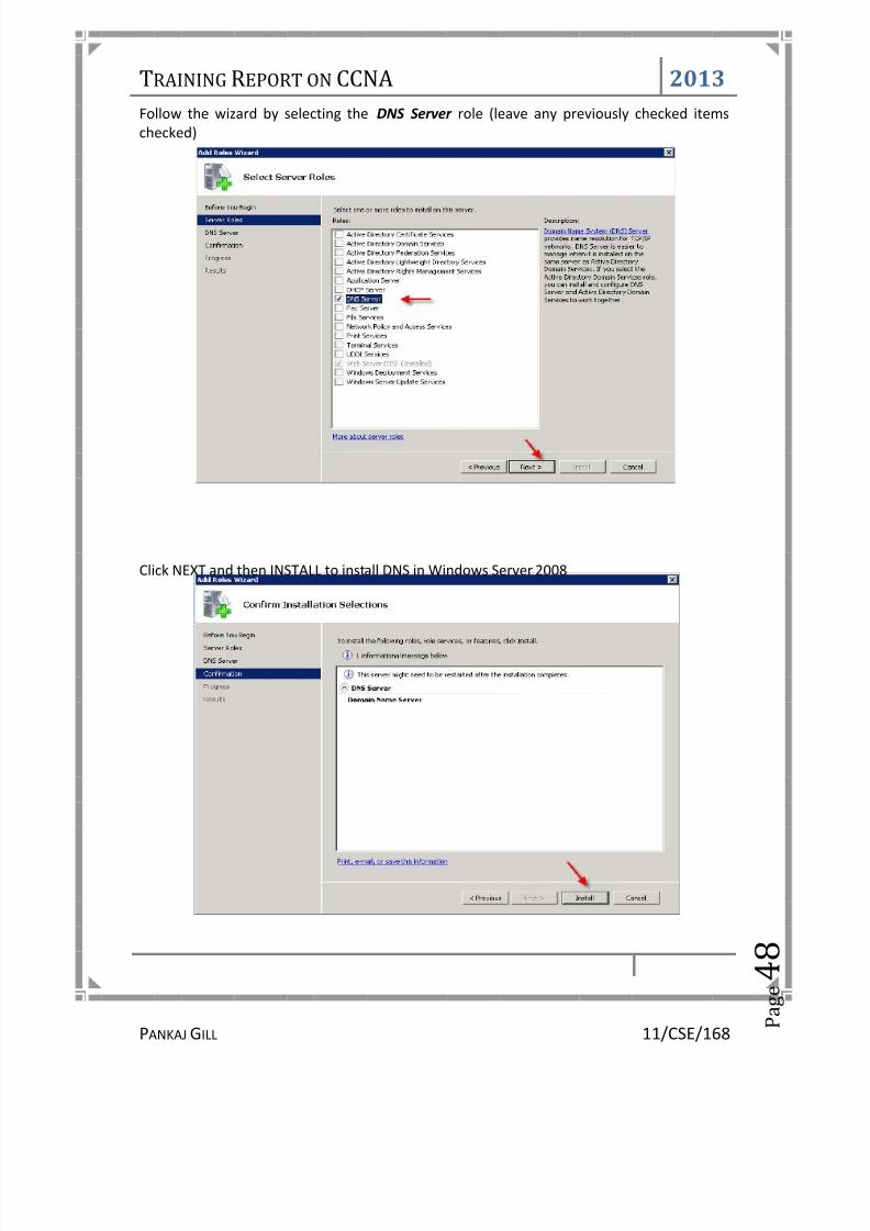
Follow the wizard by selecting the DNS Server role (leave any previously checked itemschecked)
Click NEXT and then INSTALL to install DNS in Windows Server 2008

8/13/2019 Training Report on CCNA(Cisco Certified Network Associate)
http://slidepdf.com/reader/full/training-report-on-ccnacisco-certified-network-associate 54/94
TRAINING REPORT ON CCNA 2013
PANKAJGILL 11/CSE/168 P
a g e 4
9

8/13/2019 Training Report on CCNA(Cisco Certified Network Associate)
http://slidepdf.com/reader/full/training-report-on-ccnacisco-certified-network-associate 55/94
TRAINING REPORT ON CCNA 2013
PANKAJGILL 11/CSE/168 P
a g e 5
0
2.4 DNS SERVERCONFIGURATION
From the Start menu, select Administrative Tools --> DNS to open the DNS console.

8/13/2019 Training Report on CCNA(Cisco Certified Network Associate)
http://slidepdf.com/reader/full/training-report-on-ccnacisco-certified-network-associate 56/94
TRAINING REPORT ON CCNA 2013
PANKAJGILL 11/CSE/168 P
a g e 5
1
Highlight your computer name and choose Configure a DNS Server to launch the ConfigureDNS Server Wizard.
Click NEXT and then select the first option, Create a Forward lookup zone
On the next screen, leave the default option selected, This Server maintains the zone, andclick NEXT
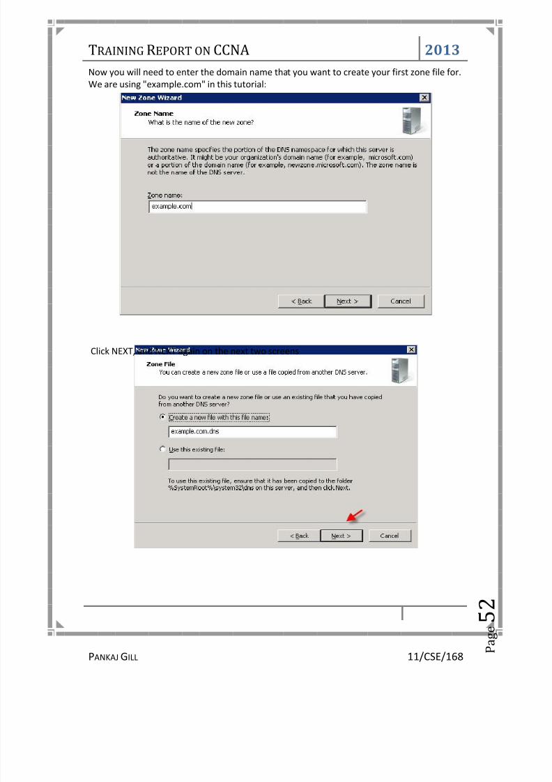
8/13/2019 Training Report on CCNA(Cisco Certified Network Associate)
http://slidepdf.com/reader/full/training-report-on-ccnacisco-certified-network-associate 57/94
TRAINING REPORT ON CCNA 2013
PANKAJGILL 11/CSE/168 P
a g e 5
2
Now you will need to enter the domain name that you want to create your first zone file for.We are using "example.com" in this tutorial:
Click NEXT, and NEXT again on the next two screens

8/13/2019 Training Report on CCNA(Cisco Certified Network Associate)
http://slidepdf.com/reader/full/training-report-on-ccnacisco-certified-network-associate 58/94
TRAINING REPORT ON CCNA 2013
PANKAJGILL 11/CSE/168 P
a g e 5
3
On the Forwarders screen, select the option " No, it should not forward queries "
ClickFINISH

8/13/2019 Training Report on CCNA(Cisco Certified Network Associate)
http://slidepdf.com/reader/full/training-report-on-ccnacisco-certified-network-associate 59/94

8/13/2019 Training Report on CCNA(Cisco Certified Network Associate)
http://slidepdf.com/reader/full/training-report-on-ccnacisco-certified-network-associate 60/94

8/13/2019 Training Report on CCNA(Cisco Certified Network Associate)
http://slidepdf.com/reader/full/training-report-on-ccnacisco-certified-network-associate 61/94
TRAINING REPORT ON CCNA 2013
PANKAJGILL 11/CSE/168 P
a g e 5
6
When done, click OK to close the window. You are now ready to set up your zone records.
Right-click on your domain name under Forward Lookup Zones , and select New Host (A orAAAA)...
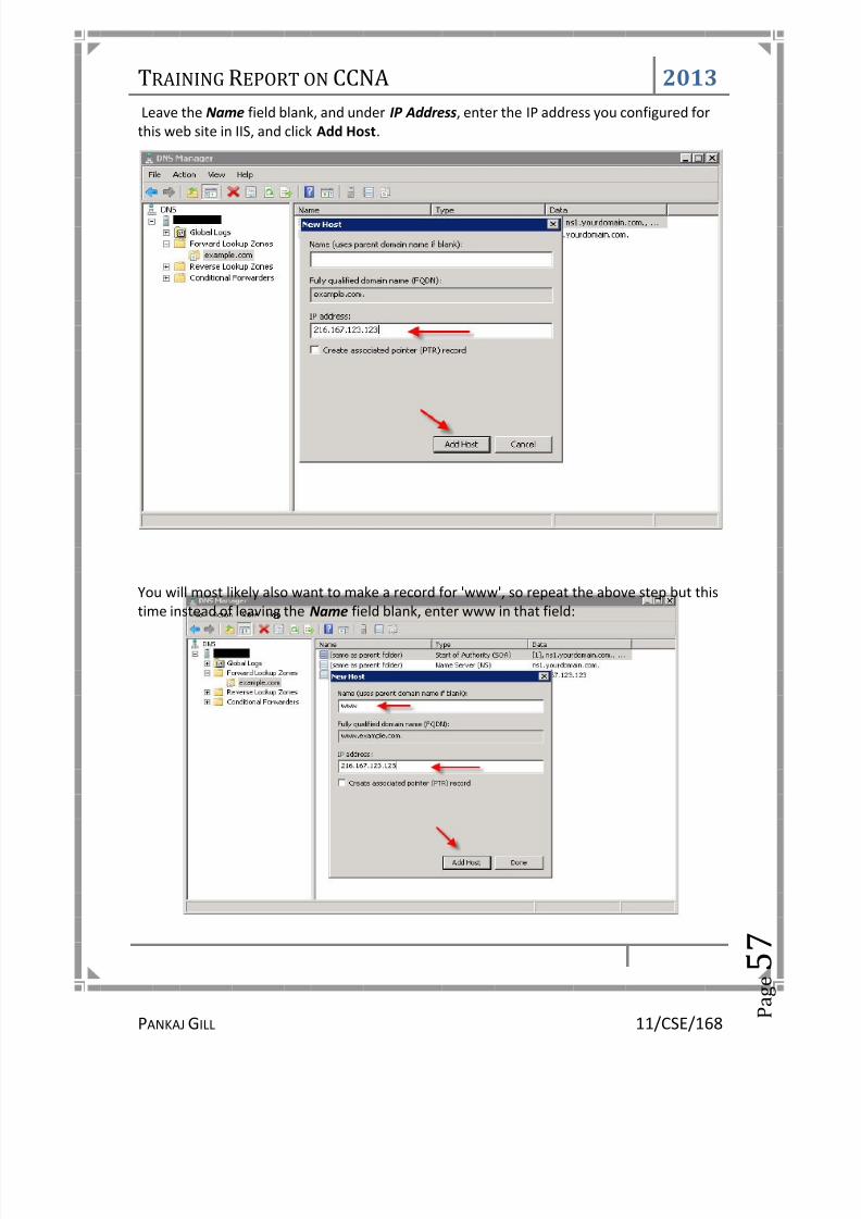
8/13/2019 Training Report on CCNA(Cisco Certified Network Associate)
http://slidepdf.com/reader/full/training-report-on-ccnacisco-certified-network-associate 62/94
TRAINING REPORT ON CCNA 2013
PANKAJGILL 11/CSE/168 P
a g e 5
7
Leave the Name field blank, and under IP Address , enter the IP address you configured forthis web site in IIS, and click Add Host .
You will most likely also want to make a record for 'www', so repeat the above step but thistime instead of leaving the Name field blank, enter www in that field:

8/13/2019 Training Report on CCNA(Cisco Certified Network Associate)
http://slidepdf.com/reader/full/training-report-on-ccnacisco-certified-network-associate 63/94
TRAINING REPORT ON CCNA 2013
PANKAJGILL 11/CSE/168 P
a g e 5
8
2.6 DISABLEDNS RECURSION
The final step you'll want to perform is to disable DNS recursion. This will help secure yourserver from a variety of DNS recursion attacks.
To disable recursion, right-click on your DNS server and go to ' Properties '.
Click the ' Advanced ' tab.
Then check the box labeled " Disable recursion "
You have now set up DNS in Windows Server 2008 and have set up DNS records for yourdomain name.
You can create additional DNS records as needed (MX, CNAME, etc) by right-clicking on thedomain under Forward Lookup Zones and selecting the appropriate type of record you wishto create.You can test that your DNS server is properly serving DNS from a Windowscommand prompt, by using the nslookup command in this format:
nslookup example.com ns1.yourdomain.com

8/13/2019 Training Report on CCNA(Cisco Certified Network Associate)
http://slidepdf.com/reader/full/training-report-on-ccnacisco-certified-network-associate 64/94
TRAINING REPORT ON CCNA 2013
PANKAJGILL 11/CSE/168 P
a g e 5
9
CCNA T RAINING REPORT
3. LAN SOLUTION3.1 LAN Solution 603.2 Specification Sheet 623.3 Router 643.4 Routing Protocols 69

8/13/2019 Training Report on CCNA(Cisco Certified Network Associate)
http://slidepdf.com/reader/full/training-report-on-ccnacisco-certified-network-associate 65/94
TRAINING REPORT ON CCNA 2013
PANKAJGILL 11/CSE/168 P
a g e 6
0
3.1 LAN SOLUTION
Customer Requirement
There is a company, which has 2 offices. And the offices are 200 meters apart. Theconnectivity between these two offices is the main requirement to be fulfilled. In eachoffice there are three different departments each department at different floor.
In building IstAt each floor there are 20 users and also at 3 rd floor there are 2 Servers.
In building IIndAt floor 1 st and 2 nd there are 20 users each. And at 3 rd floor there are 40 users.
• The bandwidth requirement of each user is 100 Mbps while the bandwidthrequirement for the server is 1 Gbps.
• All floors must be connected to a central switch to be placed at IInd floor in office2nd. And connectivity should be via optical fiber.
• Everywhere there should be structuredcabling.
•
Every switch should be provide with one GBIC slot for future connectivity of server.
• Every where smart and managed switch should be used.
Solution
By looking at the requirement it is clear that we require a switch that has got 20 ports andalso 2 GBIC slots (one for optical fiber connectivity and one free slot is demanded for futureuse).
Keeping this point into consideration we can use HCL 24 Port Managed StackableSwitch as this switch has got 24 ports and 2 GBIC slots and this switch is managed switchalso.And with this 24 port switch we will use 24 port HCL made Patch PanelAnd for connectivity of patch panel with switch we require 3 ft Patch Cord. As structuredcabling is must so we require UTP cable and I/O box and to connect PCs with I/O box werequire 7ft Patch Cord.Here we will use Cat5e UTP cable because bandwidth requirement is 100 Mbps This trendof connecting the users to the switch will be followed at each and every floor but at
floor 3 rd of building IInd there are 40 user so here instead of 1 switch we require 2switches.

8/13/2019 Training Report on CCNA(Cisco Certified Network Associate)
http://slidepdf.com/reader/full/training-report-on-ccnacisco-certified-network-associate 66/94
TRAINING REPORT ON CCNA 2013
PANKAJGILL 11/CSE/168 P
a g e 6
1
At 3rd floor of building 1 st 2 servers are also present whose bandwidth requirementis 1Gbps. So now we have two options either to connect with UTP cable or Fiber opticcable. But here we will use fiber optic as we are already using it so thee is no need to
waste money on UTP Cat 6 Cable. So here we will simply use the fiber optic patch cord toconnect the server to switch.
Now only one thing is left i.e. connection of switches to a central switch placed at 2 nd floorof IInd building.
As the connection requirement is via optical fiber so we at central location we require aswitch having all its ports as GBIC slots and no of ports should not be more than 8 as thereare only 7 24 port switches in use (one optical cable line from each switch)
Now here as the distance between the two offices is only 200 meters so here we will usemultimode optical fiber and that too FX type and as the cable is to be laid in open sooutdoor armored cable will be use.
The connectivity diagram, the bill of material and the specification sheet for the solution isgiven in the following pages.

8/13/2019 Training Report on CCNA(Cisco Certified Network Associate)
http://slidepdf.com/reader/full/training-report-on-ccnacisco-certified-network-associate 67/94
TRAINING REPORT ON CCNA 2013
PANKAJGILL 11/CSE/168 P
a g e 6
2
3.2 Specification Sheet HCL-24TMS-2S-WHCL 24 Port Managed Stackable SwitchSTANDARDS-IEEE802.3 (Ethernet) , IEEE802.3a (Fast Ethernet), IEEE802.2ab (GigabitEthernet), IEEE802.3z (1000Base SX/LX)PORTS- 24 port auto negotiation 10 base T/100 base TX2optional modular expansion ports (1000 base-T, 1000 baseLX/SX/FX)MAC Addresses - 4KBANDWIDTH-12Gbps SWITCHING RATE-6.6MbpsSNMP(Simple Network Management Protocol) - Yes,and supports RFC1157WEB MANAGEABLE-Yes
PC-C305-ECAT 5 e CABLEEnhanced CAT 5 350 MHzUTP Bulk Cable4 PairsSolid GreyLength: 305 Meters
PC-JP24-EPATCH PANEL
Unshielded 24 Port RJ-45 jack for performance @ rated 100 MbpsFully Complied to e CAT 5 T568A/B standards1.6mm metallic Patch Panel 19'' Rack Mount frame 1U Fully powder coatedBlackPC-MC3-GE3 ft. patch cord3 ft. Enhance CAT.5 350 MHzGrey Patch CordUTP twisted pair with Black Snagless Flange Boot
PC-MC7-GE7 ft. patch cord7 ft. Enhance CAT.5 350 MHzGrey Patch CordUTP twisted pair with Black Snagless Flange Boot .
PF-CM6-A-OM2Outdoor armoured Fiber optic cable - MultimodeConstruction: Corrugated steel tape armoured cable constructionMultimode – 62.5/125µm cable
No of Cores – 6 fibre core cables.Length - 1 meter

8/13/2019 Training Report on CCNA(Cisco Certified Network Associate)
http://slidepdf.com/reader/full/training-report-on-ccnacisco-certified-network-associate 68/94

8/13/2019 Training Report on CCNA(Cisco Certified Network Associate)
http://slidepdf.com/reader/full/training-report-on-ccnacisco-certified-network-associate 69/94
TRAINING REPORT ON CCNA 2013
PANKAJGILL 11/CSE/168 P
a g e 6
4
3.3 R OUTER
ROUTER INTERNAL COMPONENTS
Like a computer, a router has a CPU that varies in performance and capabilities dependingupon router platform. It has typically 4 types of memory in it.:
ROM- It is used to store the router’s bootstrap startup program, operating system software,and power-on diagnostic tests programs. We can also upgrade our ROM
FLASH MEMORY- It holds operating systems image(s). Flash memory is erasable,reprogrammable ROM. Our IOS software is present in this memory and we can upgrade italso. Flash content is retained even when we switch off or restart the router.
RAM- It is used to store operational information such as routing tables, router’s runningconfiguration file. RAM also provides caching and packet buffering capabilities. Its content islost when we switch off or restart the router. When we configure the router at that timeactually we are writing in RAM.
NVRAM- It is used to store the router’s startup configuration file. It does not lose data whenpower is switched off. So the contents of startup configuration files are maintained evenwhen we switch off or restart the router.
ROUTER’S NETWORK INTERFACES
Ethernet or Token Ring interface are configured to allow connection to a LAN. Synchronous
serial interfaces are configured to allow connections to WANs. ISDN BRI interfaces are
configured to allow connection to an ISDN WAN.
All cisco routers have a console port that provides an EIA/TIA-232 asynchronousserial connection. Console port can be connected to computers serial connection to gainterminal access to router.
Most routers also have an auxiliary port that is very similar to console port but, is typicallyused for modem connection for remote router management.

8/13/2019 Training Report on CCNA(Cisco Certified Network Associate)
http://slidepdf.com/reader/full/training-report-on-ccnacisco-certified-network-associate 70/94
TRAINING REPORT ON CCNA 2013
PANKAJGILL 11/CSE/168 P
a g e 6
5
CONFIGURING THE ROUTER
There are three methods for configuring the router:
1) Through console port:- The console port is used for configuring a router locallywith the help of a PC or a Laptop. The console port of the router is connected to the seriali.e COM port of the router. The detailed configuration is given in the section.
2) Through the AUX port:- The aux ( auxiliary ) port is accessed from a modem locatedfaraway from a router through the PSTN ( Public Switched Telephone Network ) and theconfiguration is done.
3) Through Telnet:- Line vty ( virtual terminal ) 0 to 4 are used for theconfiguring the router by telnet.
Configuring Router through Console port
We use HyperTerminal Program to open a console session and log into the router locally.This console connection allows to connect to and to communicate with router withouthaving to connect to the network to which it belongs. Now, the PC becomes the consolethat allows to enter commands and communicate directly with the router. To set up aconsole session, we use the workstation’s Windows HyperTerminal (terminal emulation)program. Now first of all we configure the COM port settings, then log into the router tointeract with the IOS command line interface (CLI). These are the com port settings:
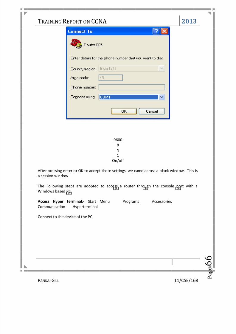
8/13/2019 Training Report on CCNA(Cisco Certified Network Associate)
http://slidepdf.com/reader/full/training-report-on-ccnacisco-certified-network-associate 71/94
TRAINING REPORT ON CCNA 2013
PANKAJGILL 11/CSE/168 P
a g e 6
6
96008N1
On/off
After pressing enter or OK to accept these settings, we came across a blank window. This isa session window.
The Following steps are adopted to access a router through the console port with aWindows based PC.
Access Hyper terminal:- Start Menu Programs AccessoriesCommunication Hyperterminal
Connect to the device of the PC

8/13/2019 Training Report on CCNA(Cisco Certified Network Associate)
http://slidepdf.com/reader/full/training-report-on-ccnacisco-certified-network-associate 72/94
TRAINING REPORT ON CCNA 2013
PANKAJGILL 11/CSE/168 P
a g e 6
7
COM 1 Setting
Hyper terminal Screen

8/13/2019 Training Report on CCNA(Cisco Certified Network Associate)
http://slidepdf.com/reader/full/training-report-on-ccnacisco-certified-network-associate 73/94
TRAINING REPORT ON CCNA 2013
PANKAJGILL 11/CSE/168 P
a g e 6
8
After connecting the router that will boot and after booting the following procedures willbe adopted.Router> enable
Now automatically prompt asking for password will appear on the screen like this:
Password:Now write password over here. This is done to secure access to router. After this
Router#will appear on the screen this shows that we are in privileged mode and now we try to enterin configuration mode.
Router# configure terminal
This is done to enter configuration mode. Now starts the configuration of routerNow we will assign IP address to each and very interface connected to router. Subnet maskshould be given with a proper care. Following steps are to be followed:
For configuring ethernet interface :
Router# config terminalRouter (config)# interface ethernet 0Router (config-if)# ip address 223.8.151.1 255.255.255.0Router (config-if)# no shutdown
Router (config-if)# exit
For configuring serial interface :
Router (config)# interface serial 0Router (config-if)# ip address 204.204.7.1 255.255.255.0Router (config-if)# no shutdownRouter (config-if)# exitRouter (config)# interface serial 1Router (config-if)# ip address 199.6.13.2 255.255.255.0
Router (config-if)# no shutdownRouter(config-if)# exit

8/13/2019 Training Report on CCNA(Cisco Certified Network Associate)
http://slidepdf.com/reader/full/training-report-on-ccnacisco-certified-network-associate 74/94
TRAINING REPORT ON CCNA 2013
PANKAJGILL 11/CSE/168 P
a g e 6
9
3.4 R OUTING P ROTOCOLS
ROUTING INFORMATION PROTOCOL (RIP)RIP is a dynamic, distance vector routing protocol. RIP uses UDP port 520 for route updates.RIP calculates the best route based on hop count. This makes RIP very fast to convergeRIP sends full table updates at regular intervals specified by the route-update timer (30seconds is the default). This means that a RIP router summarizes all routes it knows alongclassful boundaries and sends the summary information to all other RIP routing devices. RIPupdates can contain up to 25 messages.
RIP TIMERS
TIMER DEFAULT CONTROLSupdate 30 sec. Interval between route update advertisementstimeout 180 sec. Interval a route should stay 'live' in the routing table.
This counter is reset every time the router hears an updatefor this route.Flush 240 sec. How long to wait from the time the route was received to
delete a route (60 seconds after timeout).
The routing-update timer controls the time between routing updates. Default is usually 30seconds, plus a small random delay to prevent all RIP routers from sending updatessimultaneously.The route-timeout timer controls when a route is no longer available. The default is usually180 seconds. If a router has not seen the route in an update during this specified interval, itis dropped from the router's announcements. The route is maintained long enough for therouter to advertise the route as down (hop count of 16).The route-flush timer controls how long before a route is completely flushed from therouting table. The default setting is usually 120 seconds.
BASIC RIP CONFIGURATION
According to the recollection of InetDaemon, configuring a Cisco router for a basic RIPconfiguration would look something like this:
router> enable Password: router# conf t router(config)#interface ethernet 0 router(config-if)# ip address 192.168.42.1 router(config-if)# interface ethernet 1 router(config-if)# ip address 192.168.43.1 router(config-if)# exit router(config)# router riprouter(config-router)# network 192.168.42.0 router(config-router)# network 192.168.43.0router(config-router)# exit router(config-router)# ̂ z router#
The example above assumes that the interfaces that will be running RIP have IP addresses on them that fall

8/13/2019 Training Report on CCNA(Cisco Certified Network Associate)
http://slidepdf.com/reader/full/training-report-on-ccnacisco-certified-network-associate 75/94
TRAINING REPORT ON CCNA 2013
PANKAJGILL 11/CSE/168 P
a g e 7
0
within the 192.168.42.0, and 192.168.43.0 class C ranges.IGRP
• IGRP is a distance-vector routing protocol that considers a composite metric which,by default, uses bandwidth and delay as parameters instead of hop count. IGRP is
not limited to the 15-hop limit of RIP. IGRP has a maximum hop limit of 100, bydefault, and can be configured to support a network diameter of 255.• With IGRP, routers usually select paths with a larger minimum-link bandwidth
over paths with a smaller hop count. Links do not have a hop count. They are exactlyone hop.
• IGRP is available only on Cisco routers• IGRP will load-balance traffic if there are several paths with equal cost to the
destination
IGRP sends its routing table to its neighbors every 90 seconds. IGRP's default update periodof 90 seconds is a benefit compared to RIP, which can consume excessive bandwidthwhen sending updates every 30 seconds. IGRP uses an invalid timer to mark a route asinvalid after 270 seconds (three times the update timer). As with RIP, IGRP uses a flushtimer to remove a route from the routing table; the default flush timer is set to 630 seconds(seven times the update period and more than 10 minutes).If a network goes down or the metric for the network increases, the route is placed inholddown. The router accepts no new changes for the route until the holddown timerexpires. This setup prevents routing loops in the network. The default holddown timer is280 seconds (three times the update timer plus 10 seconds).
IGRP Timer Default Time
Update 90 seconds
Invalid 270 seconds
Holddown 280 seconds
Flush 630 seconds
IP ACCESS LIST
IP access lists cause a router to discard some packets based on criteria defined by thenetwork engineer. The goal of these filters is to prevent unwanted traffic in the network—whether to prevent hackers from penetrating the network, or just to prevent employeesfrom using systemsthat they should not be using.

8/13/2019 Training Report on CCNA(Cisco Certified Network Associate)
http://slidepdf.com/reader/full/training-report-on-ccnacisco-certified-network-associate 76/94
TRAINING REPORT ON CCNA 2013
PANKAJGILL 11/CSE/168 P
a g e 7
1
Key features of access lists:• Packets can be filtered as they enter an interface, before the routing decision.• Packets can be filtered before they exit an interface, after the routing decision.
• Deny is the term used in Cisco IOS software to imply that the packet will befiltered.• Permit is the term used in Cisco IOS software to imply that the packet will not be
filtered.• The filtering logic is configured in the access list.• At the end of every access list is an implied “deny all traffic” statement. Therefore, if a
packet does not match any of your access list statements, it is blocked.
Access lists have two major steps in their logic: matching and action. Matching logicexamines each packet and determines whether it matches the access-list statement. Assoon as an access-list statement is matched, there are two actions to choose from: deny andpermit. Deny means to discard the packet, and permit implies that the packet shouldcontinue on its way.

8/13/2019 Training Report on CCNA(Cisco Certified Network Associate)
http://slidepdf.com/reader/full/training-report-on-ccnacisco-certified-network-associate 77/94
TRAINING REPORT ON CCNA 2013
PANKAJGILL 11/CSE/168 P
a g e 7
2
CCNA T RAINING REPORT
4. FIREWALL4.1 Introduction 734.2 Configuring the Firewall 74
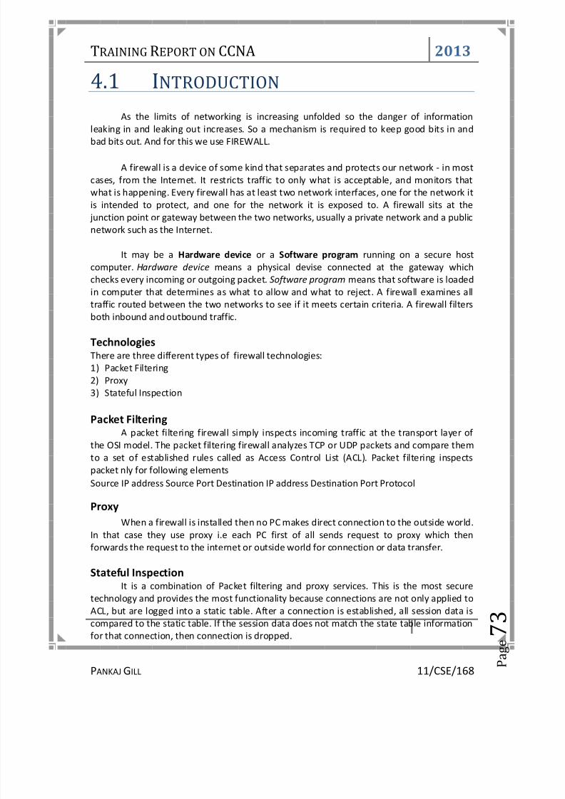
8/13/2019 Training Report on CCNA(Cisco Certified Network Associate)
http://slidepdf.com/reader/full/training-report-on-ccnacisco-certified-network-associate 78/94
TRAINING REPORT ON CCNA 2013
PANKAJGILL 11/CSE/168 P
a g e 7
3
4.1 I NTRODUCTION
As the limits of networking is increasing unfolded so the danger of informationleaking in and leaking out increases. So a mechanism is required to keep good bits in andbad bits out. And for this we use FIREWALL.
A firewall is a device of some kind that separates and protects our network - in mostcases, from the Internet. It restricts traffic to only what is acceptable, and monitors thatwhat is happening. Every firewall has at least two network interfaces, one for the network itis intended to protect, and one for the network it is exposed to. A firewall sits at the
junction point or gateway between the two networks, usually a private network and a publicnetwork such as the Internet.
It may be a Hardware device or a Software program running on a secure hostcomputer. Hardware device means a physical devise connected at the gateway whichchecks every incoming or outgoing packet. Software program means that software is loadedin computer that determines as what to allow and what to reject. A firewall examines alltraffic routed between the two networks to see if it meets certain criteria. A firewall filtersboth inbound and outbound traffic.
TechnologiesThere are three different types of firewall technologies:1) Packet Filtering
2) Proxy3) Stateful Inspection
Packet FilteringA packet filtering firewall simply inspects incoming traffic at the transport layer of
the OSI model. The packet filtering firewall analyzes TCP or UDP packets and compare themto a set of established rules called as Access Control List (ACL). Packet filtering inspectspacket nly for following elementsSource IP address Source Port Destination IP address Destination Port Protocol
ProxyWhen a firewall is installed then no PC makes direct connection to the outside world.
In that case they use proxy i.e each PC first of all sends request to proxy which thenforwards the request to the internet or outside world for connection or data transfer.
Stateful InspectionIt is a combination of Packet filtering and proxy services. This is the most secure
technology and provides the most functionality because connections are not only applied toACL, but are logged into a static table. After a connection is established, all session data iscompared to the static table. If the session data does not match the state table informationfor that connection, then connection is dropped.

8/13/2019 Training Report on CCNA(Cisco Certified Network Associate)
http://slidepdf.com/reader/full/training-report-on-ccnacisco-certified-network-associate 79/94
TRAINING REPORT ON CCNA 2013
PANKAJGILL 11/CSE/168 P
a g e 7
4
4.2 C ONFIGURING THE FIREWALL
Four basic commands are used to do a basic configuring of the firewall.1. Interface Command2. Nameif Command3. Ip-Address Nat Command4. Global Command
Interface CommandThe interface command identifies the interface hardware card, sets the speed of
the interface and enables the interface all in one command.
SYNTAX: interface hardware_id hardware_speed [shutdown]hardware_id indicates interface’s physical location on the firewall.Hardware_speed indicates connection speed.
There are various options provided to us by the firewall regarding speed.1000sxfull — Sets full-duplex Gigabit Ethernet.1000basesx — Sets half-duplex Gigabit Ethernet1000auto — Automatically detects ands negotiates full/half duplex10full — Sets 10Mbps full-duplex Ethernet100full — Sets 100Mbps full-duplex Ethernet.Shutdown — This parameter administratively shuts down the interface.
Nameif commandIt is used to name an interface and assign security level from 1 to 99. The outside and
inside interfaces are named by default and have default security values of 0 and 100,respectively. By default, the interfaces have their hardware ID. Ethernet 0 is the outsideinterface, and Ethernet 1 is the inside interface
SYNTAX: nameif hardware_id if_name security_level hardware_id Indicates the interface’s physical location on the Firewall.if_name The name by which we refer to this interface.
security_level A numerical value from 1 to 99 indicating the security level.Examples: nameif ethernet0 outside security0
nameif ethernet1 inside security100
nameif ethernet2 dmz security20
We can see the configuration by using show nameif command.
ip address CommandAll the interfaces must be configured with an IP address. The ip address command isused to configure IP addresses on the interfaces. The ip address command binds a logical
address (IP address) to the hardware ID.
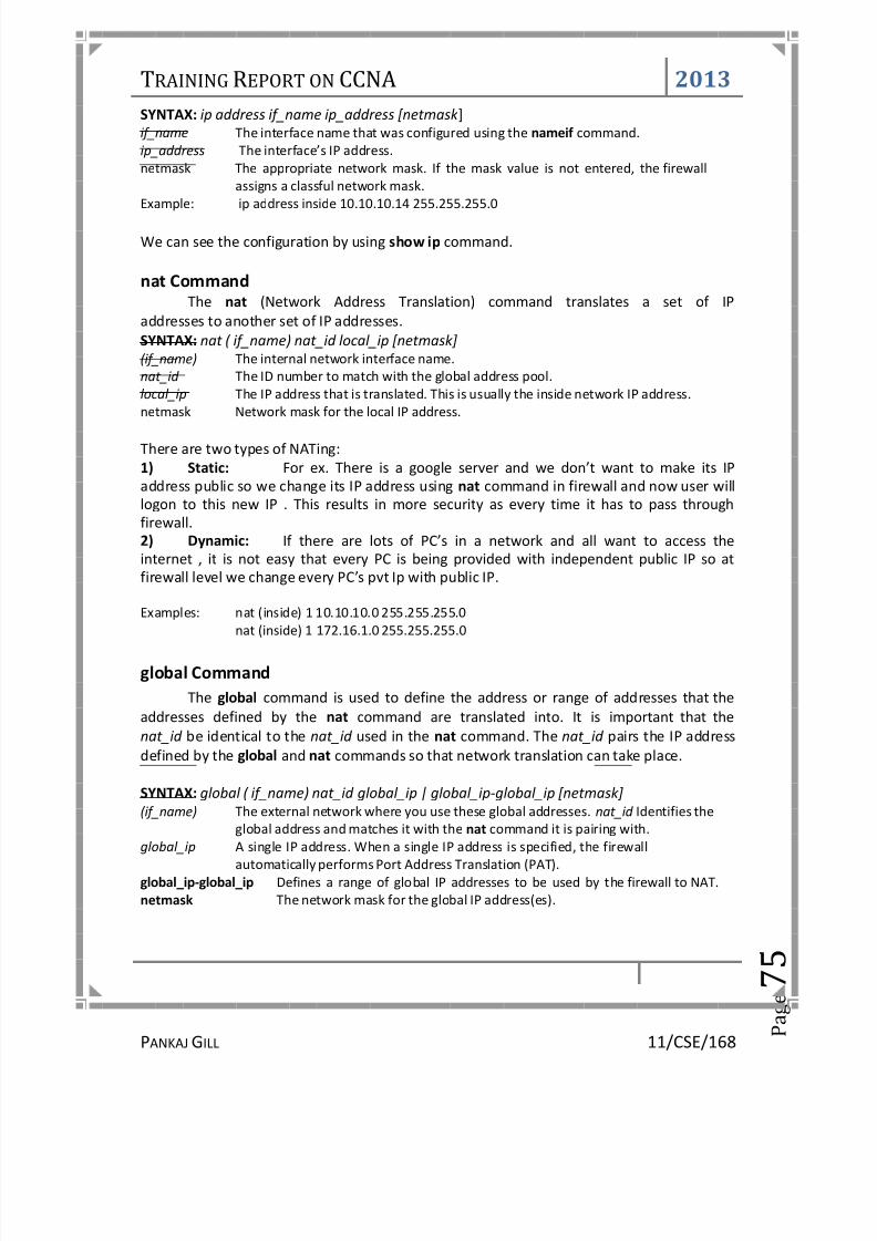
8/13/2019 Training Report on CCNA(Cisco Certified Network Associate)
http://slidepdf.com/reader/full/training-report-on-ccnacisco-certified-network-associate 80/94

8/13/2019 Training Report on CCNA(Cisco Certified Network Associate)
http://slidepdf.com/reader/full/training-report-on-ccnacisco-certified-network-associate 81/94
TRAINING REPORT ON CCNA 2013
PANKAJGILL 11/CSE/168 P
a g e 7
6
CCNA T RAINING REPORT
5. INTRUSIONDETECTION
SYSTEM(IDS)5.1 Introduction 77

8/13/2019 Training Report on CCNA(Cisco Certified Network Associate)
http://slidepdf.com/reader/full/training-report-on-ccnacisco-certified-network-associate 82/94

8/13/2019 Training Report on CCNA(Cisco Certified Network Associate)
http://slidepdf.com/reader/full/training-report-on-ccnacisco-certified-network-associate 83/94
TRAINING REPORT ON CCNA 2013
PANKAJGILL 11/CSE/168 P
a g e 7
8
Misuse Detection or Signature DetectionThis method uses specifically known patterns of unauthorized behavior to predict
and detect subsequent similar attempts. These specific patterns are called signatures. Forhost-based intrusion detection, one example of a signature is "three failed logins."
Target MonitoringThese systems do not actively search for anomalies or misuse, but instead look for
the modification of specified files. This is more of a corrective control, designed touncover an unauthorized action after it occurs in order to reverse it. One way to check forthe covert editing of files is by computing a cryptographic hash beforehand and comparingthis to new hashes of the file at regular intervals. This type of system is the easiest toimplement, because it does not require constant monitoring by the administrator. Integritychecksum hashes can be computed at whatever intervals you wish, and on either all files or
just the mission/system critical files
Passive IDSA passive IDS simply detects and alerts. When suspicious or malicious traffic is
detected an alert is generated and sent to the administrator or user and it is up to them totake action to block the activity or respond in some way.
Reactive IDSA reactive IDS will not only detect suspicious or malicious traffic and alert the
administrator, but will take pre-defined proactive actions to respond to the threat. Typicallythis means blocking any further network traffic from the source IP address or user.
IDS is required to be properly configured to recognize what is normal traffic on yournetwork vs. what might be malicious traffic and you, or the administrators responsible forresponding to IDS alerts, need to understand what the alerts mean and how toeffectively respond.

8/13/2019 Training Report on CCNA(Cisco Certified Network Associate)
http://slidepdf.com/reader/full/training-report-on-ccnacisco-certified-network-associate 84/94

8/13/2019 Training Report on CCNA(Cisco Certified Network Associate)
http://slidepdf.com/reader/full/training-report-on-ccnacisco-certified-network-associate 85/94
TRAINING REPORT ON CCNA 2013
PANKAJGILL 11/CSE/168 P
a g e 8
0
6.1 Requirement There is one CBC (Central Billing Center) which is required to be connected with 28
BGC (Bill Generation Center). As with each BGC location further locations are connected so itis required to use a router at each location.
CBC Router must have these specifications:• 4 numbers of10/100 fast Ethernet interfaces.• 20 number of V.35 interface to receive the data from coming BGC Via optical
fiber/Lease line• 2 numbers of ISDN BRI ports.• Four numbers of synchronous serial interfaces for 64 kbps lease line connectivity.
BGC Router must have these specifications:• 2 port 10/100 Mbps Ethernet Interface.• Sufficient port Serial WAN Interfaces.• Al the BGC locations are to be connected to the central location having a point to
point connectivity.• The BGC location are having a leased line connectivity of 128Kbps which can be up
gradable to 2 Mbps.• The leased Line connectivity is to be provided BY a ISP.
6.2 SolutionAs per the requirement the proposed solution is to have point to point connectivity
between the central location and the 28 BGC locations. There is a Cisco 1841 Router at eachof the BGC location. They are connected to a 2 Mbps Leased Line Modem Pair., HCL-Gateway –2M-2W, through the serial port. The modem at the customer end is connected toa modem at the ISP side. Like this way the central location having a Cisco 3845 Router isconnected to 28 nos of 2Mbps Leased Line modem pair. The connectivity diagram and thebill of material required for the solution is given in the following pages.

8/13/2019 Training Report on CCNA(Cisco Certified Network Associate)
http://slidepdf.com/reader/full/training-report-on-ccnacisco-certified-network-associate 86/94
TRAINING REPORT ON CCNA 2013
PANKAJGILL 11/CSE/168 P
a g e 8
1
T RAINING REPORT
7. WLAN(WIRELESSLAN)7.1 Introduction 827.2 Topologies 83

8/13/2019 Training Report on CCNA(Cisco Certified Network Associate)
http://slidepdf.com/reader/full/training-report-on-ccnacisco-certified-network-associate 87/94
TRAINING REPORT ON CCNA 2013
PANKAJGILL 11/CSE/168 P
a g e 8
2
7.1 IntroductionIn a traditional LAN each computer physically connects to the network via wires and
a network port. A Wireless Local Area Network (WLAN) is a network that provides thesame services but without the need for physical connections between the computersand the network. Wireless LANs offer many advantages over traditional wired networks,such as mobility, flexibility, scalability and speed, simplicity and reduced cost of installation.A WLAN typically uses radio waves, which allow network PC cards plugged into a PC/laptopto connect to a traditional Ethernet LAN. IEEE developed the 802.11 standards to providewireless networking technology like the wired Ethernet .
StandardsIEEE developed the 802.11 standards to provide wireless networking technology.
With time-to-time development in the field of technology three standards has beenfinalized. 802.11(a), 802.11(b), 802.11(g)
802.11(b) 802.11(a) 802.11(g)Max. bit rate/Raw net 11Mb/s
5.5Mb/s54 Mb/s22-26 Mb/s
54 Mb/s17-22 Mb/s
Frequency Band 2.4 GHZ 5 GHZ 2.4 GHZRange @ Max. rate 57 m 12m 19m
Unit Cost 100% 120% 110%Coverage Cost 100% 2000% 500%
No. of channels 3 8 4
IEEE 802.11a standard is the most widely adopted one because it operates at licensed 5GHZ band while other are unlicensed and also it provides max. nof channels and max. bitrate than any other standards.

8/13/2019 Training Report on CCNA(Cisco Certified Network Associate)
http://slidepdf.com/reader/full/training-report-on-ccnacisco-certified-network-associate 88/94
TRAINING REPORT ON CCNA 2013
PANKAJGILL 11/CSE/168 P
a g e 8
3
7.2 T OPOLOGIES
There are two topologies on which WLAN works:1) Infrastructure Network2) Ad hoc Network
Infrastructure NetworkIt is useful for providing wireless coverage of building or campus areas. This is a
topology used when there are many access points in a single location. By deployingmultiple Access Points (APs) with overlapping coverage areas, organizations can achievebroad network coverage. . A laptop or other mobile device may move from AP to AP whilemaintaining access to the resources of the LAN. Each client is equipped with wirelessnetwork interface card (NIC) that consists of the radio transceiver and the logic to interactwith the client machine and software. While the AP is essentially a radio transceiver on oneside and the wired backbone on the other.

8/13/2019 Training Report on CCNA(Cisco Certified Network Associate)
http://slidepdf.com/reader/full/training-report-on-ccnacisco-certified-network-associate 89/94
TRAINING REPORT ON CCNA 2013
PANKAJGILL 11/CSE/168 P
a g e 8
4
Adhoc NetworkThis topology is used when we have to interconnect mobile devices that are in the samearea (e.g., in the same room). In this architecture, client stations are grouped into a singlegeographic area and can be Internet-worked without access to the wired LAN(infrastructure network). The ad hoc configuration is similar to a peer-to-peer officenetwork in which no node is required to function as a server. In ad hoc there is no need of any AP as all devices are wirelessly connected to each other.

8/13/2019 Training Report on CCNA(Cisco Certified Network Associate)
http://slidepdf.com/reader/full/training-report-on-ccnacisco-certified-network-associate 90/94

8/13/2019 Training Report on CCNA(Cisco Certified Network Associate)
http://slidepdf.com/reader/full/training-report-on-ccnacisco-certified-network-associate 91/94
TRAINING REPORT ON CCNA 2013
PANKAJGILL 11/CSE/168 P
a g e 8
6
8.1 I NTRODUCTION
ISDN’s primary goal is the integration of voice and nonvoice services.ISDN is actuallya set of communication protocols proposed by telephone companies that allows themto carry a group of digital services that simultaneously convey data, text, voice,music, graphics, and video to end users, and it was designed to achieve this over thetelephone systems already in place.
There are two types of channels:1) B channel2) D channel
B channelBearer channels (B channels) are used to transport data. B channels are called bearer
channels because they bear the burden of transporting the data. B channels operate atspeeds of up to 64 kbps.
D channelD channels are used for signaling. They are used to establish the session before the
data is actually transfer.

8/13/2019 Training Report on CCNA(Cisco Certified Network Associate)
http://slidepdf.com/reader/full/training-report-on-ccnacisco-certified-network-associate 92/94

8/13/2019 Training Report on CCNA(Cisco Certified Network Associate)
http://slidepdf.com/reader/full/training-report-on-ccnacisco-certified-network-associate 93/94
TRAINING REPORT ON CCNA 2013
PANKAJGILL 11/CSE/168 P
a g e 8
8
8.3 ISDN F UNCTION GROUPS &REFERENCE POINTS
• Function group : A set of functions implemented by a device and software• Reference point: The interface between two function groups, including cabling
details
Router A is ordered with an ISDN BRI U reference point, referring to the I.430 referencepoint defining the interface between the customer premises and the ISP.
Router B is bought with an ISDN BRI S/T interface, implying that it must be cabled toa function group NT1 device. An NT1 function group device must be connected to the ISPline through a U reference point; the S/T interface defines the connection to Router B.Router B is called a TE1 (Terminal Equipment 1) function group device.
Non-ISDN equipment is called a TE2 (Terminal Equipment 2) device and is attached usingthe R reference point to a terminal adapter (TA) function group device.Alternatively, a TE1 can connect using an S reference point to an NT2 function group,

8/13/2019 Training Report on CCNA(Cisco Certified Network Associate)
http://slidepdf.com/reader/full/training-report-on-ccnacisco-certified-network-associate 94/94
TRAINING REPORT ON CCNA 2013
Function Groups :
1) TE1 (Terminal Equipment 1) ISDN-capable four-wire cable. Understands signalingand 2B+D. Uses an S reference point.
2) TE2 (Terminal Equipment 2): Equipment that does not understand ISDNprotocols and specifications (no ISDN awareness). Uses an R reference point,typically an RS-232 or V.35 cable, to connect to a TA
3) TA (Terminal adapter): Equipment that uses R and S reference points. Can bethought of as the TE1 function group on behalf of a TE2.
4) NT1 (Network Termination): Connects with a U reference point (two-wire) to theISP. Connects with T or S reference points to other customer premises equipment.
Reference Points:R between TE2 and TA.S between TE1 or TA and NT2.T between NT2 and NT1.U between NT1 and ISP..


