
Time Code Tutor
1
TimeLine Vista, Inc. � 1755 La Costa Meadows Drive, Suite B
San Marcos, CA � USA � (760) 761-4440 � (760) 7761-4449 FAXtimelinevista.com

Time Code Tutor
2
SMPTE Made Simple
Introduction 3
What Can You Do with SMPTE? 3
How Does SMPTE Do It? 8
Anatomy of a SMPTE Frame 11
Time Code Formats 13
VITC 16
SMPTE, MIDI and MTC 18
Using SMPTE 20
Advanced Applications 25
The Modern Electronic Recording Studio 29
SMPTE and the Digital Audio Workstation 31
The SMPTE Future 32
SMPTE Made Simple � Step By Step 33
Glossary of Industry Terms 36
Copyright © 1996
All rights reserved. No part of this publication may be reproduced, stored in a retrieval system, ortransmitted, in any form, or by any means electronic, mechanical, photocopying, recording or otherwise,without the prior written permission of TimeLine Vista, Inc.
Printed in the USA.
Part No. 73A018-9610-10
Time Code Tutor
3
Introduction
When the television broadcast industry moved from film and liveperformance to prerecorded video production, a method wasrequired to reliably synchronize and edit the new medium. Histori-cally, film rushes were lined up at the clapper board and rubberstamped with footage numbers. Film was mechanically held in syncby the sprocket holes. Unfortunately, video tape has neither ofthese attributes. This problem made it impossible to get the music,pictures, dialogue, and effects to all begin and run at the same time.
The solution was SMPTE time code. SMPTE is a signal thatcontains specific address information that can be recorded onaudio or video tape. This address information is then used toaccurately position the audio or video.
Why SMPTE?
In 1971, the Society of Motion Picture and Television Engineerschose SMPTE as the industry standard for synchronization. Itbecame officially known as SMPTE/EBU Time Code when thesociety was joined by its overseas counterpart, the EuropeanBroadcast Union (EBU). Since SMPTE/EBU is quite a mouthful,most people just say SMPTE.
What Can You Do with SMPTE?
There are hundreds of uses for SMPTE time code in every branchof audio production � records, video, film, advertising, and indus-trial productions all use SMPTE. Let�s start with the how and whyof some of the most basic applications.

Time Code Tutor
4
Synchronizing Multiple Audio Machines
Imagine you are a recording engineer. You�ve just used up all theavailable tracks on your multitrack machine, but your project is noteven close to being done. How are you going to add extra tracks?The answer is to use a second multitrack recorder.
But that solution raises another question. How do you lock the twomachines together so that the music plays back in perfect synchro-nization � the first time, and every time? You could cross yourfingers and try to hit the Play buttons on both machines at exactlythe same moment, but the odds of this approach working evenonce are very slim.
The best solution is to use SMPTE time code and a TimeLinesynchronizing system. A TimeLine Lynx-2 or Micro Lynxgenerates time code that is recorded onto the audio tapes. The timecode is then used as a common reference point. The time code actsas the glue that holds the two machines in sync.
On playback, a SMPTE time code reader reads time code fromone tape recorder and passes the timing data to a synchronizerconnected to the other tape recorder. Based on this incoming timecode, the synchronizer regulates the playback speed of the slaverecorder so that it always stays in perfect sync with the masterrecorder.
MASTERATR
SM
PT
E00
1
SLAVEATR
TIMING DATA
READS TIME CODECONTROLS SPEED
SLAVE LYNXMASTER LYNX
TIME CODE
Figure 1. Basic SMPTE Time Code Setup

Time Code Tutor
5
This simple example is the basis for all SMPTE applications. Forinstance, if you are locking to film or video using a digital audioworkstation or a sequencer, you substitute the appropriate control-ling device to suit the equipment for that application.
Locking to Picture
Suppose you have footage on videotape, and you need to create anaudio track to go with it. The audio track could be music, dialogue,effects, or all three. How do you lock the sound to picture?
The solution is to use SMPTE and a Micro Lynx or two Lynx-2modules, exactly as described in the previous audio example.SMPTE works just as well with video as it does with digital oranalog tape. You can use SMPTE to lock video to analog, digital toanalog, and even lock sound sources that don�t use tape.
VSG
VTR
SY
NC
TIM
E C
OD
E
CO
NT
RO
L
EXT SYNC
SYNC
TIM
E C
OD
E
CO
NT
RO
L
SM
PT
E00
2
POWER SUPPLY
ATR
KEYBOARD CONTROLLER
SYSTEM UNIT
RS
422
TIME CODEGENERATOR
TV MONITOR
VITC M3 DATADATA VALIDDATADATA VALID ON
OPTIONS KEYBOARDMIDI SYSTEMCOMPUTERPOWER
ACG VALIDVALID
A4 CUE TC
A1 A2 A3
VID
ASM
SOLO LOOP RDY TRKS
TCG MIDI
LIST MEM
CAPTMACROSTORCL
TRIM JOG SHTL
LAST NEXT ENTR
SYS TRAN EVNT
REC
BUSY
LOCK
REC
BUSY
LOCK
REC
BUSY
LOCK
A B C
SETUP
GRP
GROUP SELECT
DEVICE SELECT
MOTION
CALCULATOR
JOG WHEEL
F2 F3ACG F1
STATUS
1600 (48K)
1920+/–1470
(44.1K)1764
NONSTD
REFLOCK
VIDEOGEN
MIXEDCODE
VITCSYSTEM
IN
OUT
DIGITAL AUDIO CLOCK GENERATOR
SUBFR
REPLAY
EDITROLLBACK
ALLSTOP
CUELOC
RECREH
=
+
–
7 8
4 5 6
1 2 3
0 00
9
CLRTIME
PRE POST REF
SYNCP OFST ERR
IN OUT DUR
Figure 2. Synchronize to Video
Time Code Tutor
6
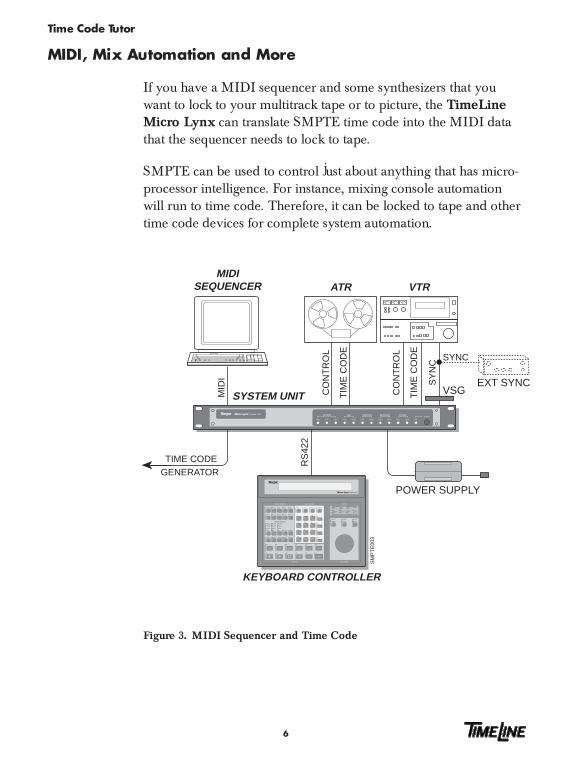
MIDI, Mix Automation and More
If you have a MIDI sequencer and some synthesizers that youwant to lock to your multitrack tape or to picture, the TimeLineMicro Lynx can translate SMPTE time code into the MIDI datathat the sequencer needs to lock to tape.
SMPTE can be used to control just about anything that has micro-processor intelligence. For instance, mixing console automationwill run to time code. Therefore, it can be locked to tape and othertime code devices for complete system automation.
TIM
E C
OD
E
CO
NT
RO
L
SM
PT
E00
3
VSG
POWER SUPPLY
VTRMIDI
SEQUENCER
KEYBOARD CONTROLLER
SYSTEM UNIT
SY
NC
TIM
E C
OD
E
CO
NT
RO
L
MID
I
ATR
EXT SYNC
RS
422
TIME CODE
SYNC
GENERATOR
A4 CUE TC
A1 A2 A3
VID
ASM
SOLO LOOP RDY TRKS
TCG MIDI
LIST MEM
CAPTMACROSTORCL
TRIM JOG SHTL
LAST NEXT ENTR
SYS TRAN EVNT
REC
BUSY
LOCK
REC
BUSY
LOCK
REC
BUSY
LOCK
A B C
SETUP
GRP
GROUP SELECT
DEVICE SELECT
MOTION
CALCULATOR
JOG WHEEL
F2 F3ACG F1
STATUS
1600 (48K)
1920+/–1470
(44.1K)1764
NONSTD
REFLOCK
VIDEOGEN
MIXEDCODE
VITCSYSTEM
IN
OUT
DIGITAL AUDIO CLOCK GENERATOR
SUBFR
REPLAY
EDITROLLBACK
ALLSTOP
CUELOC
RECREH
=
+
–
7 8
4 5 6
1 2 3
0 00
9
CLRTIME
PRE POST REF
SYNCP OFST ERR
IN OUT DUR
VITC M3 DATADATA VALIDDATADATA VALID ON
OPTIONS KEYBOARDMIDI SYSTEMCOMPUTERPOWER
ACG VALIDVALID
Figure 3. MIDI Sequencer and Time Code
Time Code Tutor
7
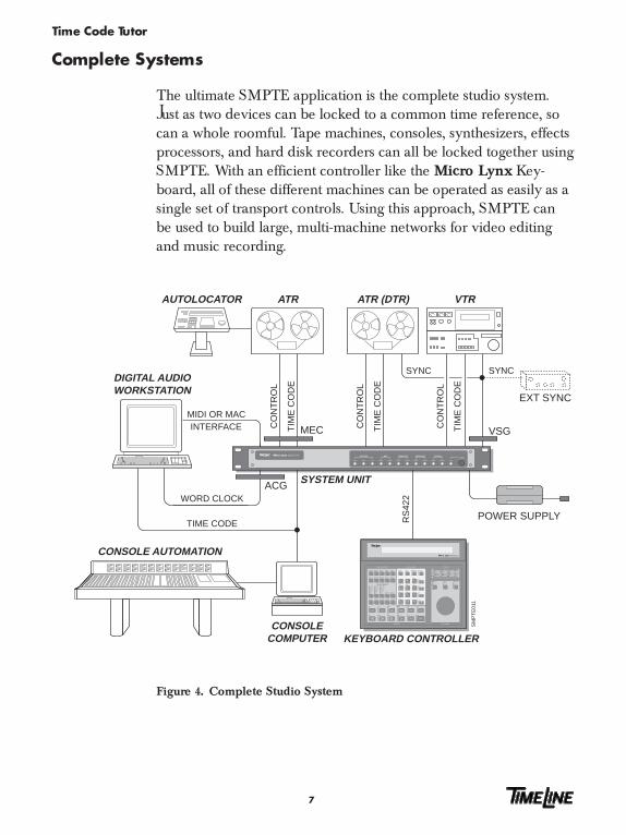
Complete Systems
The ultimate SMPTE application is the complete studio system.Just as two devices can be locked to a common time reference, socan a whole roomful. Tape machines, consoles, synthesizers, effectsprocessors, and hard disk recorders can all be locked together usingSMPTE. With an efficient controller like the Micro Lynx Key-board, all of these different machines can be operated as easily as asingle set of transport controls. Using this approach, SMPTE canbe used to build large, multi-machine networks for video editingand music recording.
WORD CLOCK
SM
PT
E01
1
ATR
CONSOLECOMPUTER
MEC
ACG
VSG
POWER SUPPLY
ATR (DTR)AUTOLOCATOR VTR
DIGITAL AUDIOWORKSTATION
CONSOLE AUTOMATION
KEYBOARD CONTROLLER
SYSTEM UNIT
MIDI OR MACINTERFACE
SYNC
TIME CODE
TIM
E C
OD
E
CO
NT
RO
L
TIM
E C
OD
E
CO
NT
RO
L
TIM
E C
OD
E
CO
NT
RO
L
EXT SYNCR
S42
2
SYNC
A4 CUE TC
A1 A2 A3
VID
ASM
SOLO LOOP RDY TRKS
TCG MIDI
LIST MEM
CAPTMACROSTORCL
TRIM JOG SHTL
LAST NEXT ENTR
SYS TRAN EVNT
REC
BUSY
LOCK
REC
BUSY
LOCK
REC
BUSY
LOCK
A B C
SETUP
GRP
GROUP SELECT
DEVICE SELECT
MOTION
CALCULATOR
JOG WHEEL
F2 F3ACG F1
STATUS
1600 (48K)
1920+/–1470
(44.1K)1764
NONSTD
REFLOCK
VIDEOGEN
MIXEDCODE
VITCSYSTEM
IN
OUT
DIGITAL AUDIO CLOCK GENERATOR
SUBFR
REPLAY
EDITROLLBACK
ALLSTOP
CUELOC
RECREH
=
+
–
7 8
4 5 6
1 2 3
0 00
9
CLRTIME
PRE POST REF
SYNCP OFST ERR
IN OUT DUR
VITC M3 DATADATA VALIDDATADATA VALID ON
OPTIONS KEYBOARDMIDI SYSTEMCOMPUTERPOWER
ACG VALIDVALID
Figure 4. Complete Studio System
Time Code Tutor
8
How Does SMPTE Do It?
If you know precisely where a piece of program is and how fast it�splaying, you can use this information to control other machines sothat they are all in the right place at exactly the same time. SMPTEdoes this; it is an absolute timing reference that indicates both the speedand position of a tape as it travels across a tape machine transport.
What You Can Do with a Speed Reference
Many pre-SMPTE sync codes could only indicate speed. The mostwidely used was a control track or pilot tone. A pilot tone is an audiosignal derived from a stable source (historically 60 Hz AC wallcurrent). By reducing the voltage with a suitable transformer, theresulting continuous sine wave could be recorded on tape.
Machine speed is normally regulated by monitoring tach pulses fromthe tape machine�s capstan motor. These pulses indicate how manytimes the capstan revolves in a given time interval, in the same wayan automobile�s tachometer indicates how fast an engine is turning.
When playing back a tape with a pilot tone, the sine wave on tape iscompared with a reference sine wave coming from the wall currentor some other guaranteed signal.
If the tape slows down, the frequency of the pilot tone, or thenumber of cycles that tick by each second, will decrease. If the tapespeeds up, the frequency will increase. A controlling device, tied intothe tape machine�s capstan motor, senses the difference betweenthe reference tone and the pilot tone on tape; and varies the speedof the tape machine motor to make the two match up again.
Time Code Tutor
9
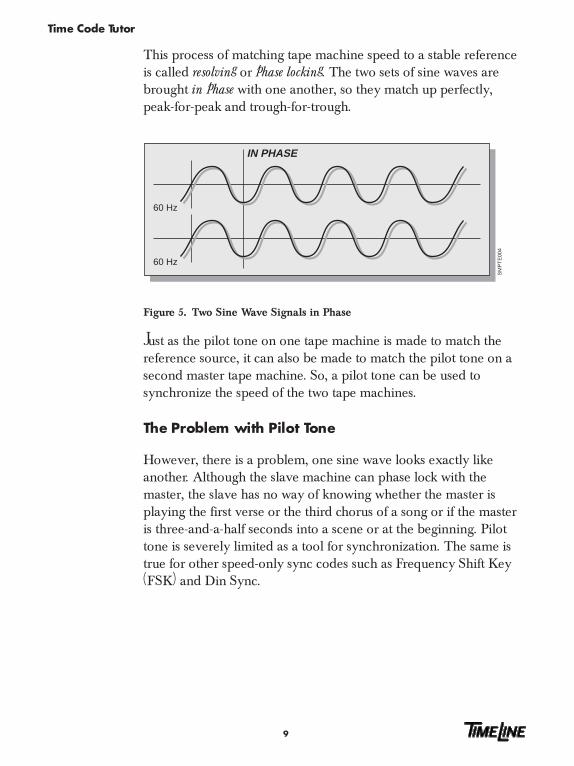
This process of matching tape machine speed to a stable referenceis called resolving or phase locking. The two sets of sine waves arebrought in phase with one another, so they match up perfectly,peak-for-peak and trough-for-trough.
60 Hz
SM
PT
E00
4
60 Hz
IN PHASE
Figure 5. Two Sine Wave Signals in Phase
Just as the pilot tone on one tape machine is made to match thereference source, it can also be made to match the pilot tone on asecond master tape machine. So, a pilot tone can be used tosynchronize the speed of the two tape machines.
The Problem with Pilot Tone
However, there is a problem, one sine wave looks exactly likeanother. Although the slave machine can phase lock with themaster, the slave has no way of knowing whether the master isplaying the first verse or the third chorus of a song or if the masteris three-and-a-half seconds into a scene or at the beginning. Pilottone is severely limited as a tool for synchronization. The same istrue for other speed-only sync codes such as Frequency Shift Key(FSK) and Din Sync.

Time Code Tutor
10
To work, both the master and slave must be carefully lined up atthe beginning of playback. There is no way to run the machinesaccurately to the middle of the program material because the slavenever knows where the master is. The slave only knows how fastthe master is playing.
SMPTE: What You Can Do with a Speed and Position Reference
SMPTE indicates not only tape speed, but also tape position.SMPTE time code is a complex digital signal. It is equivalent to thesimple, analog pilot tone signal, but it also has a unique numberassigned to each cycle of the sine wave.
Time code is recorded onto tape as an audible signal. The signal isa rapid-fire series of blips, which are read by a microprocessor as aunique number. This number is an address that consists of separatenumbers for hours, minutes, seconds, and fractions of a second thatare called frames.
If you have a gunshot at the climactic scene of a suspense melo-drama, SMPTE can tell you the exact address or location on tapeof the gunshot. SMPTE tells you that the gunshot occurs 1 hour,31 minutes, 12 seconds, and 19 frames into the film. You can moveto the exact spot on tape where that gunshot occurs and replace theexisting blast with a more convincing sample from the soundeffects engineer.
Using SMPTE, the master machine can find anything on a tape, andall of the slave machines will chase the master to the same spot.This is a long way from just locking one sine wave to another androlling from the top. SMPTE brings you into the realm of positionaccuracy.

Time Code Tutor
11
Anatomy of a SMPTE Frame
A SMPTE frame or word consists of 80 bits that convey SMPTE�smessage in hours, minutes, seconds, and frames. Each bit is repre-sented by a binary 1 or 0 that is specifically encoded for recordingonto tape. The method used is called biphase encoding. Thiscoding reverses the signal polarity halfway through a bit to repre-sent a 1 and leaves the bit polarity unchanged to represent a 0. Acontinuous string of these 80-bit words is recorded linearly alongthe tape to form the time code.
Each frame is broken up into 16 groups of 4 bits and a 16-bit syncword.
³ Eight 4-bit groups are assigned to the hours, minutes, seconds,and frame number.
³ Eight 4-bit groups are user bits. They are reserved for informa-tion such as ID, reel numbers, session, dates, or another timecode number.
³ The remaining bits form a sync word, to provide directioninformation and mark the end of the 80-bit frame.
³ The time code reader uses the direction sense bits to determinewhether the tape is running forward or backward.
³ The sync word is a series of preset 1s that allow the speed andphase of the two time codes to be read and compared by theLynx or Micro Lynx module to establish synchronization.
SECUSERBITS
FRAMESUSERBITS
FRAMES USERBITS
SEC USERBITS
MIN USERBITS
MIN USERBITS
HOURS USERBITS
HOURS USERBITS
SYNCWORD
BORDER BITS
DIRECTION SENSE
0 4 8 12 16 20 24 28 32 36 40 44 48 52 56 60 64 68 72 76 0
START OF FRAME
Figure 6. Time Code Address

Time Code Tutor
12
SMPTE words (one for each frame) are recorded along the lengthof the tape; hence the name Longitudinal Time Code (LTC). Thecode�s design and organization make it suitable for a very widerange of play speeds, both forward and backward.
The frequency of the LTC signal is always proportional to the tapespeed. However, the signal cannot be read in stop or freeze-framemode. Consequently video frequently uses another form of timecode: Vertical Interval Time Code (VITC), which can be reliablyread in stop and at very slow play speeds.
Time Code Tutor
13
Time Code Formats
There are 60 minutes in an hour; 60 seconds in a minute, but howmany frames are there in a second? Frame rate is the term used toexpress the number of frames per second in SMPTE time code.Frame rate was originally measured as one-half the power linefrequency.
Since there are different power line frequencies in the U.S. andEurope, time code has several different formats, defined by theframe rate used in each country.
National Television Standards Committee (NTSC)
Wall current in the U.S. has a frequency of 60 Hz, which makes30 frames per second the standard frame rate for American blackand white television.
Phase Alternate Line (PAL)
In Europe, the standard wall current frequency is 50 Hz. Therefore,the standard for European color television, the PAL format, is25 frames per second.
Drop Frame (DF)
What about American color TV? When it was invented by RCA,they reduced the American black and white frame rate of 30 framesper second to 29.97 frames per second, to allow both color encod-ing and compatibility with existing black and white television sets.This format became the standard color TV format for America.

Time Code Tutor
14
The problem is that 30-frame time code running at this ratemeasures slightly slower than real time.
60 sec x 30 frames/sec = 1800/min x 60 min/hr = 108,000 frames60 sec x 29.97 frames/sec = 1798.2/min x 60 min/hr = 107,892 frames
Difference = 108 frames
So for every hour, the time code is 108 frames short. In editing, ifyou are just a few frames off, you might make your lead guitaristend his solo two chords early. To correct this problem, a time codeformat called Drop Frame (DF) was developed. Drop frame skipsthe first two frame counts in each minute (with the exception ofminutes 00, 10, 20, 30, 40, and 50) to force the time code to matchthe clock time.
Film
Film has run at a frame rate of 24 frames per second ever sinceThomas Edison invented it. Although this is a non-standard timecode, sometimes it is used in the field.
Different Frame Rate Formats
The important thing to remember is that SMPTE conveys twopieces of information: tape speed and tape position.
Frame rate, is the speed at which the code will run. Frame type(30/DF/25/24) is the way frame positions are counted.
30 Thirty frames per second can be drop frame or non dropframe. If you select drop frame, the actual frame count isreduced by 108 frames per hour.
25 Twenty-five frames per second is the European standard.
24 Twenty-four frames per second is the film standard.

Time Code Tutor
15
Table 1. Frame Rates
Counting Counting Method Displayed TimeRate (Hz) (Frames per Second) Accuracy Application
24 24 frame Real Time Motion pictures & film
25 25 frame Real Time EBU standardfor European television
29.971 30 drop frame3 Real Time NTSC standardfor USA & Japan
29.971 30 non-drop frame4 0.1 % Slow USA & Japan
30.002 30 drop frame3 0.1 % Fast Non-standard
30.002 30 non-drop frame4 Real Time USA & Japan
Notes:
1. 29.97: Generated by all color television sync generators (i.e., almost all syncgenerators built after 1970). This speed is the speed at which a black burstsignal runs. (Do not confuse a black burst with black and white. A black burstis a standard color signal with a color of black.) Use this as your standardframe rate unless you are an expert and have a reason not to.
2. 30.00: Usually available only in the internal crystal mode of a time codegenerator, or from black-and-white television sync generators. Don�t use thisnon-standard speed unless you are an expert and have a good reason. Thisspeed is sometimes used in conjunction with motion picture film systems.
3. Skips 108 frames/hour at regular intervals.
4. Many users prefer 30 (full frame) counting because no numbers skip in thecounting sequence, even though the elapsed time accuracy at 29.97 frame rateis slightly different from real time.
Time Code Tutor
16
VITC
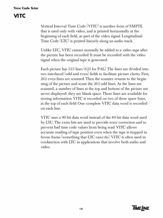
Vertical Interval Time Code (VITC) is another form of SMPTEthat is used only with video, and is printed horizontally at thebeginning of each field, as part of the video signal. LongitudinalTime Code (LTC) is printed linearly along an audio track.
Unlike LTC, VITC cannot normally be added to a video tape afterthe picture has been recorded. It must be recorded with the videosignal when the original tape is generated.
Each picture has 525 lines (625 for PAL). The lines are divided intotwo interlaced (odd and even) fields to facilitate picture clarity. First,262 even lines are scanned. Then the scanner returns to the begin-ning of the picture and scans the 263 odd lines. As the lines arescanned, a number of lines at the top and bottom of the picture arenever displayed; they are blank space. These lines are available forstoring information. VITC is recorded on two of these spare lines,at the top of each field. One complete VITC data word is recordedon each line.
VITC uses a 90-bit data word instead of the 80-bit data word usedby LTC. The extra bits are used to provide error correction and toprevent bad time code values from being read. VITC allowsaccurate reading of tape position even when the tape is stopped infreeze frame (something that LTC can�t do). VITC is often used inconjunction with LTC in applications that involve both audio andvideo.

Time Code Tutor
17
SM
PT
E00
6
VITC TIME CODE
START OF FRAME
CONTROL TRACK
AUDIO TRACK 1
ADDRESS TRACK
AUDIO TRACK 2
1F BG2BG1 10F 1S BG3 10S BG4 1M BG5 10M BG6 1H BG7 10H BG8 CRC
VITC TIME CODE VITC TIME CODE
ONE HORIZONTAL PICTURE LINE
VIDEO INFORMATION
END OF FRAME
Figure 7. Video Tape and VITC Time Code

Time Code Tutor
18
SMPTE, MIDI and MTC
MIDI is not the same as SMPTE, even though both are binarycodes. They each carry very different types of information.
SMPTE, as we�ve seen, answers the questions �Where are we,� and�How fast are we going?�
MIDI however, answers an equally vital but different question,�What do we do now?� It answers that question for synthesizers,drum machines, and other electronic music devices. MIDI is thelanguage that a computer uses when it tells a synthesizer, �Playmiddle C, play it mezzo forte, and play it now!�
But when is now? If we�re talking about playing back an electroniccomposition in concert, now is a relative term. Now might be thethird beat of the fourteenth measure, and whether that beat hits at10:31 or 10:32 PM is something no one usually notices. However, ifthat beat has to coincide with the cocking of an assassin�s pistol in afeature film thriller, or coincide with a soul-wrenching wail from avocalist on audio tape, it becomes necessary to pin down whennow is.
Traditionally, a MIDI sequencer was slaved to SMPTE. Manypopular sequencers can read incoming SMPTE and lock theirmusical tempos (their beats per minute) to the time code.
This solution works beautifully, but it leaves the film or TV com-poser with the awkward situation of going back and forth betweentwo dissimilar sets of numbers. While his sequencer counts beatsand measures, his work print, cue list, director�s instructions andeverything else that pertains to the visual side of the equation, allcount in hours, minutes, seconds, and frames. The two sets ofnumbers never coincide neatly, which forces the composer to pullall sorts of tricks on his sequencer.

Time Code Tutor
19
MIDI is a computer code that uses 8-bit data words or bytes thatcannot contain SMPTE�s 80-bit word. This limitation is why MIDITime Code (MTC) was invented. MTC takes SMPTE time codeand translates it into the MIDI data format. To translate SMPTEinto MIDI, the MIDI time code format transmits a MTC messagebyte every 1/4 frame. The first two 1/4 frame bytes contain only theframes. The next two MTC bytes convey the seconds, the next twothe minutes, the next two the hours, and so forth.
This process takes exactly two SMPTE frames to complete. As soonas one complete SMPTE address is transmitted, the MTC genera-tor updates the time code by two frames and starts again.
The TimeLine Micro Lynx can take SMPTE from a master tapeand generate MTC. Using MTC, the film/TV composer can nowuse a cue-sheet style program, as well as conventional music, andwork exclusively with hours, minutes, seconds, and frames.
Although SMPTE and MTC are not the same thing, they make apowerful combination when the Micro Lynx puts them together.
Time Code Tutor
20
Using SMPTE
Any SMPTE time code application involves three basic functions.
First you need a generator to produce the actual SMPTE signal thatgoes onto tape. Second, you need a reader to read the SMPTE timecode from tape. Finally, there�s the job itself, i.e., what you want toaccomplish.
SMPTE can be used with a resolver, to ensure that a single tapemachine runs at a consistent speed. It can also be used with anautolocator that stores a number of SMPTE addresses in memoryand chases to those addresses on command, or when you want tolock one or more devices to a master tape machine with a synchro-nizer.
In the early days, a different device was often required to performeach of these functions. Today, products from TimeLine performthem all. The Lynx-2 Time Code Module with a KeyboardControl Unit is a compact, high-end, high-performance unit. TheMicro Lynx is a high-performance time code system for project orsmaller studio systems.
Things To Know About Generating Time Code
Time code that is generated and striped on tape will ultimately beplayed back and read, so you must determine the optimum levelfor your master tape before you generate the time code. Mastertapes are generally printed at about -6 dB. If you print code at alevel that is too low, the reader will have trouble reading it. If youprint the code too hot, it will bleed audibly onto adjacent tracks.
Even when they are printing at the correct level, many engineersleave a blank track next to the time code track called a guard band.
In multitrack formats, time code is usually printed on the outermosttrack to eliminate the need to leave two blank tracks (one track oneither side of the time code). For example, time code is usuallyprinted on track 24 on a multitrack machine.
Time Code Tutor
21
When printing time code in video and digital audio applications,make sure that the time code generator and machines are properlyreferenced together. Your generator must be connected to the sameexternal video sync signal as the video or digital machine, other-wise, when synchronizing, the video machines will start off in theright place, but will slowly drift apart.
With digital audio machines, the sample rate or word clock shouldbe locked to the time code. Normally, you lock to the time code byusing a video sync signal as a common timing reference for thegenerator and the digital machine. Set both to �EXT VID� beforeprinting time code. If you don�t have a sync pulse generator, theMicro Lynx Video Sync Generator (VSG) option card can beinstalled and used to generate a referenced composite sync signalfor your video or digital machine.
Specific types of video sync include black burst, color bars andcomposite. These video sync signals are often collectively called housesync, or the signal that�s universal throughout the production facilityor house. To reference your generator to video sync, set it to �EXTVID� mode and connect a video sync signal. Referencing to videosync ensures that the tapes you are striping will have a commonreference and will sync properly on playback.

Time Code Tutor
22
Reshaping Time Code
Reshaping, or cleaning up the time code signal, should be donewhen you are dubbing time code from one tape to another. If youjust copy time code from one tape to another without reshaping it,the time code will deteriorate quickly because of generation loss,and eventually it will become unusable. Reshaping is not recom-mended when the time code on tape has begun to deterioratebadly.
SMPTE007
TIME CODE IN RESHAPED TIME CODELYNX-2 MODULEFILM VITC 25
DF
30
24
OFFSET
SYNC PT
RDR
ERR
GEN
RESOLVE
LOCK
REH
REC
24
25
DF
30
SER
VITC
PILOT
LTC
TRANSPORT
VSO
GEN
ONLINE
N/STD
TACH
JAM UB
JAM TC
TACH
MAINS
INT
RDR
AUX
VID
GENERATOR
29.97
422SPEED
H M LRMT BWL VARI
ON
Figure 8. Reshaping Time Code
When reshaping, existing code is passed through the reader,which puts out �squared-up� code. If a tape has been copiedseveral times or is very worn, the time code is likely to havedropouts or bad spots that a time code reader won�t be able toread. The reshape output of a time code reader can only put out aclean copy of its input. So if the code drops out completely, thereshaped output will have a corresponding dropout. To overcomethis, the code must be regenerated rather than reshaped.
Regeneration or Jam Sync
Jam Sync, is a generator function that offers a better alternative toreshaping. It is used to create a new time code that is related to anexisting time code on tape. It is very useful for repairing a break inan existing time code track, or creating a continuous time codetrack from an edited or discontinuous track. Code is read up to thelast good address, then the generator uses the next consecutiveaddress to generate new code.

Time Code Tutor
23
SMPTE008
ATR (VTR)
JAM SYNCGEN OUT
TIME CODEVALUE
LYNX MODULE
TC IN
GENERATORREADER
Figure 9. Jam Sync
Jam sync is used extensively in video editing; where differentpieces of tape, each with different time code, are spliced together.Jam sync provides the resulting program with continuous timecode. TimeLine�s Micro Lynx and Lynx-2 both have manual andautomatic jam modes, that let you quickly repair or create new timecode tracks to overcome the problems detected with bad code.
About Time Code Readers
A wide band reader, like the Lynx-2 Time Code Module orMicro Lynx, reads time code even at the high tape speeds used forFast Forward and Rewind. Wide band reader capabilities areessential, since SMPTE addresses provide the only accurate meansof locating positions on tape.
If time code on tape becomes unreadable, the TimeLine readersautomatically search for the next best sync source on tape. AfterSMPTE, the reader searches for serial time code, then pilot tone,and finally tach pulses that are derived from the rotation of the tapemachine�s capstan motor.
Time Code Tutor
24
Synchronizer Essentials
A synchronizer reads time code from two or more machines. Then,by manipulating the speed of each machine�s capstan, the synchro-nizer forces the two machines to play tape at the same speed. Thisprocess is called locking. The Micro Lynx system offers phase or synclock mode.
Phase or Sync Lock
Phase or Sync Lock emulates the old control track or pilot tonemethod of synchronization. The TimeLine system reads the timecodes, synchronizes the transport, and takes any deliberate offsetsinto account. Once the system is locked, the slaves only use thespeed information that is derived from the time code. Specific timecode addresses are ignored.
This setup allows the tape machines to stay locked even if the timecode relationships change. The time code change is reported, butthe synchronizer makes no corrective action.
Time Code Tutor
25
Advanced Applications
Video Editing
Video editing is the process of assembling raw footage into a finishedtelevision program. Shooting the raw footage is part of televisionproduction, and video editing is part of the post-production process.
An average television program such as a sitcom or a documentaryhas action that constantly shifts from one scene to another � fromindoors to outdoors, for example. Within a given scene, theperspective also shifts from one camera to another. Each camerashoots the scene at a different angle.
During editing, multiple video machines are each loaded withfootage of different scenes that have been shot by different cam-eras. The potential for chaos is great. Fortunately, each reel of rawfootage is striped with SMPTE time code, and each frame has aspecific and unique location or address. In some cases, both LTCand VITC are on the tape.
During editing, selected scenes of raw footage are transferred ontoa master video tape in the sequence they will appear in the finishedshow. The master video tape contains the master or program timecode.
A video editor locks the source video machines loaded with rawfootage to the master video machine. Additionally, one or moreaudio tape machines may be locked to the master. These machinescontain the production audio, which includes the dialogue andincidental sounds recorded during shooting of the raw footage.
Time Code Tutor
26
Video editing is normally a two-stage operation. Offline editing isfirst. The person editing the show receives work tapes, i.e., copiesof all the raw footage, with time code �burned in� so that it�s visiblein one corner of the picture. Any footage initially shot on film, isusually transferred to video at this point. From the work tapes, abasic sequence of scenes is selected. For example, the second sceneshould be the bar room brawl that occurs, say, between addresses�05:40:59:11 and 05:44:12:22 on one of the raw footage reels. In thefinished program, this scene needs to start exactly six minutes, fiveseconds and nine frames (00:06:05:09) into the show and run to00:09:18:20.
When all the scenes have been sequenced in this manner, an EditDecision List (EDL) is compiled. The EDL is a complete, comput-erized directory of the location of the scenes in the show, alongwith the addresses that locate each scene in the raw footage.
Later, the project moves to online editing. The EDL is down-loaded, and the final video master is assembled from the originalraw footage. This raw footage was set aside while the work tapesendured the rigors of the offline editing.
Audio-For-Video
Just like the raw video footage, all of the audio elements that gointo a video production must be assembled. This procedure isgenerally known as audio-for-video or audio post-production. There areseveral different branches of audio post because many differenttypes of sound sources go into a typical video show.
Time Code Tutor
27
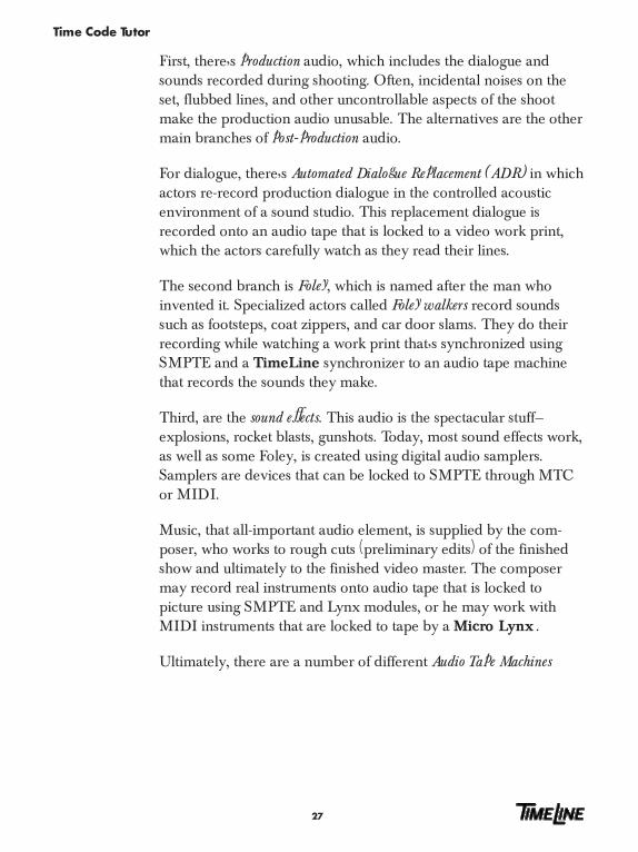
First, there�s production audio, which includes the dialogue andsounds recorded during shooting. Often, incidental noises on theset, flubbed lines, and other uncontrollable aspects of the shootmake the production audio unusable. The alternatives are the othermain branches of post-production audio.
For dialogue, there�s Automated Dialogue Replacement (ADR) in whichactors re-record production dialogue in the controlled acousticenvironment of a sound studio. This replacement dialogue isrecorded onto an audio tape that is locked to a video work print,which the actors carefully watch as they read their lines.
The second branch is Foley, which is named after the man whoinvented it. Specialized actors called Foley walkers record soundssuch as footsteps, coat zippers, and car door slams. They do theirrecording while watching a work print that�s synchronized usingSMPTE and a TimeLine synchronizer to an audio tape machinethat records the sounds they make.
Third, are the sound effects. This audio is the spectacular stuff�explosions, rocket blasts, gunshots. Today, most sound effects work,as well as some Foley, is created using digital audio samplers.Samplers are devices that can be locked to SMPTE through MTCor MIDI.
Music, that all-important audio element, is supplied by the com-poser, who works to rough cuts (preliminary edits) of the finishedshow and ultimately to the finished video master. The composermay record real instruments onto audio tape that is locked topicture using SMPTE and Lynx modules, or he may work withMIDI instruments that are locked to tape by a Micro Lynx .
Ultimately, there are a number of different Audio Tape Machines

Time Code Tutor
28
(ATRs) or film dubbers with the finished music, dialogue, and effects.These ATRs are locked to the video master using a TimeLinesystem controller, such as the Keyboard Control Unit or ConsoleControl Unit. Then the multiple audio sources are balanced by amixing console to provide a finished audio master for the program.Because this can be quite an elaborate process, many modern post-production facilities use automated mixing consoles that store mixdata, such as fader moves, and mutes in computer memory.
SM
PT
E01
0
SYNC
RS422 RS422
SYNC
SYNC
TIM
E C
OD
E
CO
NT
RO
L
KEYBOARD CONTROL UNIT
KCU POWERSUPPLY
LYNX-2 (2)
EXT SYNC
VTRATRAUTOLOCATOR
LYNX-2 (1)
CO
NS
OLE
DA
TA
CONSOLE CONTROL UNIT
SYSTEM SUPERVISOR
KEYBOARD CONTROL UNIT POWER SUPPLY
LYNX KEYBOARD CONTROL UNIT
CONSOLE
SYNC
TIM
E C
OD
E
CO
NT
RO
L
DIAGNOSTICS
LYNX SYSTEM SUPERVISOR
CAPTURESYSTEM STATUS
TEST SELECTAUX
SELECT
GND LEVEL BEEP
DIAGNOSTICTERMINAL
EMERGENCYALL STOP
MAINS
1
0
THRESHLEVEL
FILM VITC 25
DF
30
24
OFFSET
SYNC PT
RDR
ERR
GEN
RESOLVE
LOCK
REH
REC
24
25
DF
30
SER
VITC
PILOT
LTC
TRANSPORT
VSO
GEN
ONLINE
N/STD
TACH
JAM UB
JAM TC
TACH
MAINS
INT
RDR
AUX
VID
GENERATOR
29.97
422SPEED
H M LRMT BWL VARI
ON
FILM VITC 25
DF
30
24
OFFSET
SYNC PT
RDR
ERR
GEN
RESOLVE
LOCK
REH
REC
24
25
DF
30
SER
VITC
PILOT
LTC
TRANSPORT
VSO
GEN
ONLINE
N/STD
TACH
JAM UB
JAM TC
TACH
MAINS
INT
RDR
AUX
VID
GENERATOR
29.97
422SPEED
H M LRMT BWL VARI
ON
LOCK
CODE
BUSY
REC
AUX
LOCK
CODE
BUSY
REC
AUX
LOCK
CODE
BUSY
REC
AUX
LOCK
CODE
BUSY
REC
AUX
LOCK
CODE
BUSY
REC
AUX
IN
7 9
4 5 6
1 2 3
0 00
DUR
SYNCP OFST ERR
PRE POST REF
TIME CLR
=
CAPT
STO
+
SETUP
RCL
-
RDY
TRKS
TCG
GRP
A B C D E F
8OUT
TRIM
SYS
EVNT
LYNX CONSOLE CONTROL UNIT
LAST NEXT
MEM
SOLO
Figure 10. Automated Mixing System
The Modern Electronic Recording Studio
Time Code Tutor
29
TIME CODE
SM
PT
E01
3
POWER SUPPLY
KEYBOARD CONTROLLER
RS
422
WORD CLOCK
MACINTERFACE
ACG
DIGITAL AUDIOWORKSTATION
TIM
E C
OD
E
CO
NT
RO
L
ATR
TIM
E C
OD
E
CO
NT
RO
L
ATRMIDI
SEQUENCER
MID
I
KEYBOARD
MIDI
EFFECTS PROCESSOR
VITC M3 DATADATA VALIDDATADATA VALID ON
OPTIONS KEYBOARDMIDI SYSTEMCOMPUTERPOWER
ACG VALIDVALID
A4 CUE TC
A1 A2 A3
VID
ASM
SOLO LOOP RDY TRKS
TCG MIDI
LIST MEM
CAPTMACROSTORCL
TRIM JOG SHTL
LAST NEXT ENTR
SYS TRAN EVNT
REC
BUSY
LOCK
REC
BUSY
LOCK
REC
BUSY
LOCK
A B C
SETUP
GRP
GROUP SELECT
DEVICE SELECT
MOTION
CALCULATOR
JOG WHEEL
F2 F3ACG F1
STATUS
1600 (48K)
1920+/–1470
(44.1K)1764
NONSTD
REFLOCK
VIDEOGEN
MIXEDCODE
VITCSYSTEM
IN
OUT
DIGITAL AUDIO CLOCK GENERATOR
SUBFR
REPLAY
EDITROLLBACK
ALLSTOP
CUELOC
RECREH
=
+
–
7 8
4 5 6
1 2 3
0 00
9
CLRTIME
PRE POST REF
SYNCP OFST ERR
IN OUT DUR
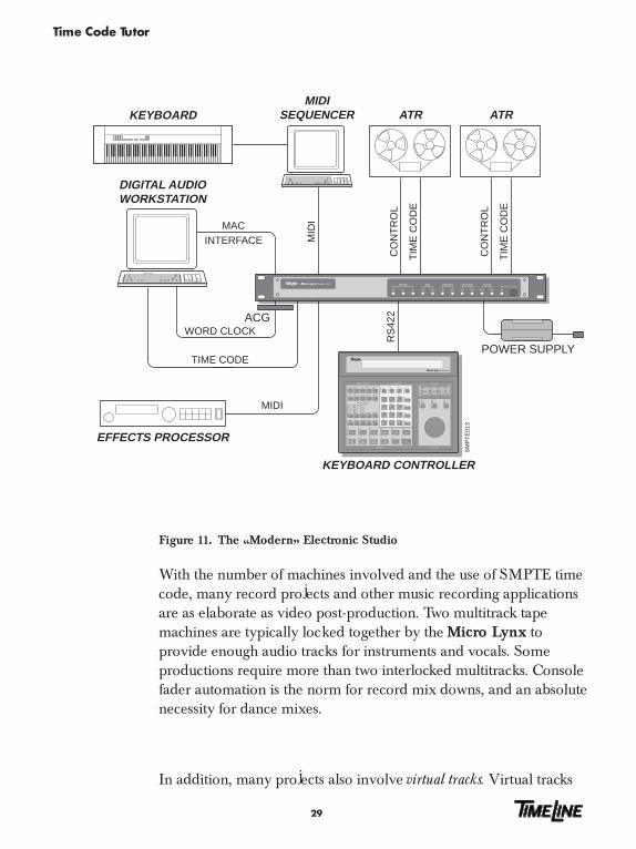
Figure 11. The �Modern� Electronic Studio
With the number of machines involved and the use of SMPTE timecode, many record projects and other music recording applicationsare as elaborate as video post-production. Two multitrack tapemachines are typically locked together by the Micro Lynx toprovide enough audio tracks for instruments and vocals. Someproductions require more than two interlocked multitracks. Consolefader automation is the norm for record mix downs, and an absolutenecessity for dance mixes.
In addition, many projects also involve virtual tracks. Virtual tracks

Time Code Tutor
30
are MIDI synthesizer and drum machine parts that are synchro-nized to tape, and played back live in real time, rather than beingrecorded onto multitrack. The Micro Lynx provides the all-important SMPTE to MIDI translation.
MIDI is also the protocol used to automate effects processors, suchas digital reverbs, and harmonizers. These MIDI devices canchange programs midsong, and even perform real time individualparameter changes midprogram. Some mixing consoles, particu-larly those designed for personal use and project studios also haveMIDI automated switching or mixing features.
Just about every device in the recording studio, including tapemachines, consoles, effects processors, and electronic instruments,can now be automated using SMPTE, MIDI, and the appropriateTimeLine equipment.
SMPTE and the Digital Audio Workstation

Time Code Tutor
31
The Digital Audio Workstation (DAW) is an important tool for post-production and music recording. The DAW records, edits, manipu-lates, and mixes multiple tracks of audio in a single digital environ-ment. It�s a self-contained, self-sufficient system. At some pointhowever, the DAW must sync with the real world and eventuallybe slaved to picture or a master tape machine.
This situation can present a problem. DAWs are always referencedto their own internal sample rate clock and can use time code tolocate and park at a specific SMPTE address. When that addresscomes up on the master tape, the DAW goes into play, but it�srunning �wild� because it isn�t locked to anything except its owninternal clock. This scenario is only a little better than attempting topress two start buttons on two machines at the same time.
The Micro Lynx Digital Audio Clock Generator (ACG) Cardoption solves the problem. It provides a way to reference the digitalaudio workstation to the master time code using word clock(sample rate) data or AES/EBU digital audio bit stream, whichcontains timing data. The ACG card generates a digital audio clockthat is locked to the Micro Lynx system reference, and the DAWuses it to lock and run its internal sample rate clock.
You can even varispeed the master tape. The Digital Audio ClockCard automatically adjusts the ACGs word clock rate. If the tapespeeds up or slows down, the DAW will adjust to match the newplay speed (within the limits of the disk system).
As we enter the digital era, time code continues to be an important,practical solution for communication and control of multiple piecesof equipment. And the TimeLine Micro Lynx and Lynx-2machine control systems offer the most complete solution to tameSMPTE and MIDI time code.
Time Code Tutor
32
TIME CODE
TIM
E C
OD
E
CO
NT
RO
L
SM
PT
E00
9
VSG
POWER SUPPLY
VTR
KEYBOARD CONTROLLER
SY
NC
TIM
E C
OD
E
CO
NT
RO
L
ATR (DTR)
EXT SYNC
RS
422
SYNC
TIM
E C
OD
E
CO
NT
RO
L
ATR
MEC
WORD CLOCK
MIDI OR MACINTERFACE
ACG
DIGITAL AUDIOWORKSTATION
SYNC
A4 CUE TC
A1 A2 A3
VID
ASM
SOLO LOOP RDY TRKS
TCG MIDI
LIST MEM
CAPTMACROSTORCL
TRIM JOG SHTL
LAST NEXT ENTR
SYS TRAN EVNT
REC
BUSY
LOCK
REC
BUSY
LOCK
REC
BUSY
LOCK
A B C
SETUP
GRP
GROUP SELECT
DEVICE SELECT
MOTION
CALCULATOR
JOG WHEEL
F2 F3ACG F1
STATUS
1600 (48K)
1920+/–1470
(44.1K)1764
NONSTD
REFLOCK
VIDEOGEN
MIXEDCODE
VITCSYSTEM
IN
OUT
DIGITAL AUDIO CLOCK GENERATOR
SUBFR
REPLAY
EDITROLLBACK
ALLSTOP
CUELOC
RECREH
=
+
–
7 8
4 5 6
1 2 3
0 00
9
CLRTIME
PRE POST REF
SYNCP OFST ERR
IN OUT DUR
VITC M3 DATADATA VALIDDATADATA VALID ON
OPTIONS KEYBOARDMIDI SYSTEMCOMPUTERPOWER
ACG VALIDVALID
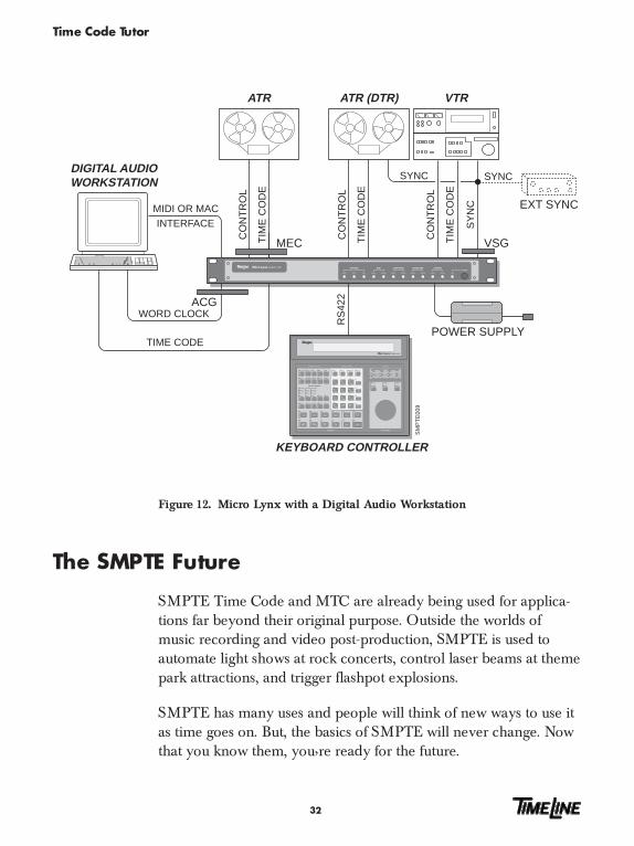
Figure 12. Micro Lynx with a Digital Audio Workstation
The SMPTE Future
SMPTE Time Code and MTC are already being used for applica-tions far beyond their original purpose. Outside the worlds ofmusic recording and video post-production, SMPTE is used toautomate light shows at rock concerts, control laser beams at themepark attractions, and trigger flashpot explosions.
SMPTE has many uses and people will think of new ways to use itas time goes on. But, the basics of SMPTE will never change. Nowthat you know them, you�re ready for the future.
Time Code Tutor
33
SMPTE Made Simple � Step By Step
Working with Film or Video
Goal: To create, edit, mix, and layback to the original master orcut a final audio track for film or video.
1. Get direct copy of the time code master with a window dub(where the SMPTE time code shows up in a little window atthe bottom of the screen).
2. Record time code to tapes that are to be used in the produc-tion. Preset a time code generator to the master tape time code.For analog audio, set the transport to fixed speed and recordtime code to the time code track or an edge track if a multi-track recorder. For digital audio, reference the transport andthe time code generator to video sync and record to the timecode track. Allow at least 15 seconds before the master time forsynchronization. Additionally, dub a copy of the originalmaster copy that you received in Step 1 above. You will workfrom this production master. This is very important so you don�twear out your original while you work.
3. Set start times and the correct time code format to match for allapplications software being used. The time code format forNTSC video is drop frame code running at 29.97 fps. Remem-ber if you are using a Digital Audio Workstation, you will needto ensure it is properly referenced. This may require the use ofa Digital Audio Clock Generator such as the Micro LynxACG Card, to resolve the workstation sample rate clock. Allsoftware should be set to chase to external time code.
4. Replace the master copy with the new working dub, set thetransports to external control and slave all machines andsoftware to this. Begin your work.
5. Make sure the synchronizer and all of the transports you areusing are resolved to house video sync. It is very importantthat each transport play each tape at exactly the correct speedall referenced to a common source. In this way time code

Time Code Tutor
34
striped tapes can be played back on a machine in a differentstudio and will still be accurate to the original.
6. After completing the production and before mixing, replacethe master dub with the original master copy, lock machines,and confirm timing of program material making sure that nodrift occurs over time.
7. Mix program to final format required for layback. This wouldeither be a deck that is resolved and has a pre-striped tape(Step 3 above), or a deck that the final mix is recorded to whilesimultaneously regenerating time code.
8. Layback the mixed audio program to the original master bysyncing the final mix tape to the master video tape and insert-ing the audio program on to the audio tracks of the mastertape. It is at this step when working with film, a Mag audiotrack (or �full coat�) would be cut and sent to the lab to becombined with the master negative.
9. Finally, archive files, make safety copies, complete track sheetand tape box information, turn off lights, and go home.
Music Only Production
Goal: To use SMPTE time code for synchronizing analog ordigital multitrack audio tape recorders and computer-based MIDIsoftware systems and digital audio workstations.
1. The most important point to remember even in music-onlyproduction is to resolve all machines being used � both whenworking with tape that is being striped for the first time or withpre-striped tapes. That way time code will always run at thecorrect speed.
2. Always regenerate or reshape time code when copying fromone tape to a new tape. Simply copying the time code frommachine to machine is not optimal as the time code degradeseach time it is copied.
Time Code Tutor
35
3. Always print time code on an edge track (usually track 8 on an8 track ATR, track 16 on a 16 track ATR, etc.) and try to leavethe adjacent track free of any recorded audio as there is atendency for time code to bleed or be heard on the adjacenttrack. Optimize the record levels so that time code is printed atabout -5 db and no lower than -12 db. Listen closely to makesure that time code can not be heard in your audio program.
4. Use non-drop frame time code running at 29.97 fps (NTSCrate) as this is the standard for music only production.
Time Code Tutor
36
24 �24� refers to both the film-standard speed and code type.
25 �25� refers to both the EBU/PAL speed and code type.
29.97 �29.97� refers to a SMPTE frame rate only, in frames-per-second.
30 �30� refers to a SMPTE frame rate only, in frames-per-second.
Address SMPTE/EBU time code address. Also referred to as time codevalue. A specific and unique address in the time code datastream.
A set of SMPTE or EBU time code numbers indicating a specificposition on tape. A complete SMPTE address includes hours,minutes, seconds, and frames.
ADR Automated Dialog Replacement. A technique for replacingproduction dialog in the studio.
AES/EBU A professional standard for the high speed transfer of two chan-nels of digital audio data. Developed jointly by the Audio Engi-neering Society (AES) & the European Broadcast Union (EBU).
Amplitude Signal displacement from a zero point. The amplitude of ananalog signal is the measurement of voltage increase or decrease.
Analog Audio One means of recording and reproducing sound, using fluctuat-ing electronic voltages to replicate audio waveforms.
ATR Audio Tape Recorder.
Autolocator A device that can hold multiple tape locations in memory andchase to those locations on command, using SMPTE addresses,tach pulses, or control track pulses to find a desired point ontape.
Bandwidth The frequency range of a signal.
Binary Numerical A system for expressing numerical values using two digits,System 0 and 1. The binary system is used in digital audio, SMPTE,
MIDI, and other microprocessor-related data formats.
Glossary
Time Code Tutor
37
Biphase Encoding The way in which SMPTE time code gets encoded onto tape.It expresses binary �1� and binary �0�.
Biphase encoding reverses the signal polarity halfway througha bit to represent a �1� and leaves the bit polarity unchanged torepresent a �0�.
BIT Short for BInary digiT; a number which is either one or zero.
Blanking Interval The blanking interval occurs at the end of a frame. Videoinformation is absent during the blanking interval. Theinterval occurs when the CRT electron gun scanner goes fromthe bottom right corner of the screen to the beginning of thenext field in the top left corner.
BNC Bayonet-Nut Coupler. Used for the connection of video andhigh frequency clock signals.
Byte A group of related binary data or a word, which can be read,interpreted, and acted on by a microprocessor. A byte is madeup of bits, which can be either a 0 or 1.
Capstan On a tape recorder the motor driven spindle that drives thetape across the heads. A synchronizer controls the capstanmotor to keep the tape in sync.
Code Type See Time Code Type
Configuration See Setup Mode. The process of defining the user-selectedoperational parameters, such as defining a specific transportor lifter-defeat mode.
Control Track A synchronizing signal on the edge of a tape, which providesa reference for tracking control and tape speed.
CPU Central Processing Unit. A computers central microprocessor,responsible for all system logic and memory organization.
DAW Digital Audio Workstation. Usually refers to a computer-based, hard disk recording and editing environment.
Decibel (dB) The unit of measurement used to describe a sounds ampli-tude. The measurement is relative and logarithmic.

Time Code Tutor
38
DF Drop frame. See drop frame
Differential Input Input amplifier that is designed to amplify the differencebetween two signals and reject common signals.
Differential Output Output amplifier designed to provide two signals that arecompletely identical but with opposite phase.
Digital Literally �using digits�. A Computer is a typical digital device.
Digital Audio Audio signal that has been converted (digitized) into a streamof binary numbers for storing or transmitting, that are equiva-lent to the original analog audio signal.
Display Numeric display. Time Code/Message Display.
Drop Frame Drop frame is one of the two SMPTE code types, and is theNTSC color television standard. When using this code type,108 specific frame numbers are �dropped� for each hour oftime code. See the Appendix for more detailed time codeinformation.
EBU EBU time code is a 25-frame code running at 25 fps.
Edit Decision List A list, either on paper or in computer memory, of time(EDL) code addresses indicating successive scenes of source video
footage that make up a complete program.
EDL See Edit Decision List.
ERR Error or offset error. Indicates that the display shows thedifference between the actual position of the machine inrelation to where the system expects it to be.
EXT VID A source of external video sync used by the synchronizer as atiming reference. Can be color black, black burst, color barsor composite sync.
Filter A digital or analog process which has the effect of removingunwanted frequencies from an audio signal.
Foley The process of adding incidental sounds, such as footsteps,door slams, etc., to a video program or motion picture; namedafter the man who invented it.

Time Code Tutor
39
Format See Time Code Format.
Frame A single image on a motion picture film or a television pictureformed from two interlaced fields. One complete videoscanning cycle, one complete SMPTE time code word.
Frame Lock Frame lock maintains synchronization between the Masterand Slave transports, using the position information availablein the time code address.
Frame Rate The number of frames that go by in one second of audio, filmor video tape. Film and different types of video all havedifferent frame rates.
30 30 fr/s Monochrome TV, & audio
NTSC 29.97 fr/s Color videotape, TV operations
PAL 25 fr/s European TV, European Broadcast, &audio
Film 24 fr/s Film cameras & projectors
Frequency The number of wave cycles that occur in a given period oftime (one second). The unit of measurement is the Hertz (Hz).
Generate Running the system time code generator so that time code isavailable at the rear panel GEN OUT jack.
Generator A time code generator. Each synchronizer has a time codegenerator. This generator receives its speed reference fromone of the internal or external sources.
GEN REF Generator reference. Also referred to as reference source.
Groups A group of machines that have a defined positional relation-ship. Machines are placed in group mode for synchronization.Machines in a group will operate together as if they were asingle transport.
GRP See Groups.
Guard Band A track of multitrack tape adjacent to the sync track (such asSMPTE or Control Track), which is left unrecorded in orderto prevent the time code from bleeding onto the audio pro-gram material.
Time Code Tutor
40
HH:MM:SS:FF Hours:Minutes:Seconds:Frames. A SMPTE time code addressor value.
Initialize Completely clear the synchronizers RAM. Press and hold theCLR key while you power-up the module.
INT XTAL A system speed reference that is derived from the unit�s internalcrystal. This reference should be selected when an externalreference (video or word clock) is not required.
Jam Sync A technique used to start a time code generator from anotherrunning time code. It can be used to recreate missing time codeor to external existing time code on tape.
Jam Time Code The Jam Time Code or Jam Sync function. See Jam Sync.
KCU Keyboard Control Unit. TimeLine�s external machine controlunit. The KCU provides centrally-controlled access to all syn-chronizers in a system.
LCD Liquid Crystal display. The KBD display is of this type.
LED Light emitting diode.
Lifter A tape transport�s head lifter mechanism. Tape machines nor-mally lift the tape off the heads when in wind (FFW/RWD).The synchronizer intelligently controls the machines lifteroperation, to read time code when required.
Local Transport The machine or transport that the synchronizer is connected toand controlling.
Lock Transport is synchronized with the system reference GEN REF.
LTC Longitudinal Time Code. Time code information encoded inbinary coded decimal (BCD) form which is recorded as anaudio signal on a designated track of a VTR or an ATR.
Machine Machine refers to the generic concept of tape record/playbackhardware.
Machine Control The wide ranging field of transport control. This covers basictransport operation, synchronization and more complex func-tions such as electronic editing.
Time Code Tutor
41
MACROS Preprogrammed or user programmed keys permitting complexkey sequences to be stored and executed by pressing a singlekey. Sometimes known as smart keys.
MIDI Musical Instrument Digital Interface. This serial data languageis used by microprocessors in synthesizers, sequencers, drummachines, signal processors, and computers. It provides music-al pitch and rhythm information, synthesizer performanceparameters, song position markers, stop/start/continue com-mands for sequencers and computers, and synchronizing datacalled MIDI Clock, which is based on 24 pulses per quarter-note. MIDI is frequently used with SMPTE for sync-to-tapefunctions.
MIDI is transmitted between microprocessors at 32.125 kBitsper second. It can also be used by lighting systems and mixingconsoles.
MIDI Time Code A MIDI system real time message that assigns a unique addressfor a specific moment in time. MIDI Time Code takes twoframes to transmit a complete address in bursts of data that aretransmitted every 1/4 frame.
Motion Controls The basic set of six transport control keys (Play, Stop, Rec, Reh,Rwd & FF) and the six additional transport control functions(Loc, Cue, Allstop, Rlb, replay & Edit).
MTC See MIDI Time Code.
Multitrack A tape machine, analog or digital which has more than twoaudio tracks.
N/A Not available. Not active. Not applicable.
Non Drop Frame NDF or ND is one of the two SMPTE code types and is theblack & white television standard. When using this code type,every frame of time code is counted in real time. See the Ap-pendix for more time code information.
Non-contiguous Not a continuous, predictable sequence. i.e., 1, 2, 4, 5, 6, 8, 9 isa non-contiguous number sequence.

Time Code Tutor
42
NTSC A system of coding color information for television transmis-sion used primarily in the USA and Japan. Named after theNational Television System Committee.
Offset Offset is the difference between two time codes at the point atwhich they are to be synchronized. Offsets are subframe-accurate and are displayed using the HH:MM:SS:FF format.Offsets are always applied to the slave machines.
Oversampling A process by which a computer interpolates between adjacentdigital audio numbers to provide in-between values andreduce quantization error.
PAL Phase Alternate Line. PAL is another name for the 25 timecode format, which is the standard for European color andB&W television.
Phase Lock A mode of synchronizer operation that uses phase informa-tion derived from SMPTE time code and, after initial syn-chronization, ignores specific frame addresses. It is also calledSync Lock.
Pilot Tone The Pilot output signal is a sinusoidally-shaped output, whichis always two times the frame rate of the time code that isbeing referenced or generated.
Post-production Activities that take place after the raw footage has been shotfor a video program or motion picture. Includes video editingand a number of audio processes, such as ADR, Foley, andmixing.
Production The initial stages in the making of a film or television pro-gram, which includes the shooting of raw footage and record-ing of production audio.
RAM Random Access Memory. The module�s configuration param-eters are stored in battery-backed RAM. And recalled eachtime the unit is turned on.
Rate Frame rate or speed. See Frame Rate or Speed.
Time Code Tutor
43
REF SRC Reference source. The signal used to determine the rate atwhich the generator and synchronizer will run. The referencesource can be thought of as the system time base. The refer-ence source can be internal crystal, external video, MAINS,or external pilot tone or the time code reader (VSO).
Register The generator register is the module�s memory buffer thatholds numeric time code values that are entered or captured.Each synchronizer also has reader, sync point, offset, user bitand error registers.
Reshape The output signal is the same as the input signal, but it hasbeen reshaped with correct rise time values and a fixedvoltage output. This type of output does not correct for bit ortiming errors.
Resolving A technique for regulating the play speed of a tape machineby matching the rate of pulses recorded on tape with a pulserate from another stable source or a master tape machine.
RLB See Rollback.
Rollback The rollback function is used to rewind machines by a prede-termined amount from the current position. The defaultrollback time is 15 seconds.
S-PDIF A consumer standard similar to AES/EBU for the high speedtransmission of digital audio data. Jointly developed by Sonyand Philips.
Sequencer A device that can record performance data for synthesizersand other electronic instruments and then, on playback, passthat data on to the instruments so that they�ll play what hasbeen recorded. Modern sequencers use MIDI as their com-munications protocol.
Serial A type of computer interface where all data is sent down asingle wire or pair of wires one bit at a time. Examples ofserial interfaces are RS422 & RS232.
Serial Port The physical computer connection through which serial datais transmitted and received.
Time Code Tutor
44
Setup Mode The process of defining the user-selected operational param-eters, such as defining a specific transport or lifter-defeatmode.
Shuttle Fast-wind. Fast-forward or Rewind.
SMPTE Society of Motion Picture and Television Engineers. Anindustry standards committee. The group responsible fordeveloping SMPTE time code.
SOLO Literally �using alone�. A tape transport in solo will be con-trolled by itself, without affecting other transports in thesystem.
Speed Speed, Frame Rate and Rate are synonymous. Time codespeed is counted in frames-per-second (fps). SMPTE timecode has two speeds: 30 fps and 29.97 fps.
SU See System Unit
SUBF UBITS Sub frame user bits.
Sync Lock See Phase Lock.
Sync Word Included at the end of every 80-bit time code word is a 16-bitSync Word. The sync word provides direction and Phase-lockspeed information, and marks the end of each time codeword.
Synchronizer A device that reads time codes recorded on two or more tapemachines, compares the codes, and adjusts the machine�s tapepositions and speeds based on the results of that comparison.
System BUS When two or more synchronizers are used to form a system, acommunications link must be established between the mod-ules. This is done by looping from one module to the next, viathe RS422 ports on the rear panel of the system unit.
System Unit The rack mounting part of the Micro Lynx machine controlsystem. The unit contains the control (CP) and machinecontrol (MC) microprocessors.
Time Code Tutor
45
TCA Time Code Address. The HH:MM:SS:FF bits of the TC word.
TCG See Time Code Generator.
Time Code Format Time code format defines both the frame rate and code typebeing used. Example: To describe a time code format as30 NDF is to say that the frame rate is 30 fps and the code typeis non-drop frame. Simply saying either 30 or drop framedefines only part of the SMPTE time code.
Time Code A special signal generator designed to generate and transmitGenerator SMPTE time code at one of the international formats & rates.
Time Code Reader A counter designed to read and display SMPTE time code.
Time Code Type The word �type� is the key to understanding this phrase.Type defines the counting method that is employed by thetime code module. There are two SMPTE types: 30 (alsocalled non-drop �ND� or non-drop frame �NDF�) and dropframe (DF). EBU and film types are the same as their respec-tive speeds, 25 and 24.
Toggle To toggle is to consecutively press a key several times in orderto step through a series of choices.
Track A place for the storage of audio information. Analog taperecorders have one or more physical tape tracks. MIDI se-quencers and digital audio workstations provide areas ofmemory to store control or audio data.
Track Select The process of enabling (arming) specific tape machine tracksfor recording.
Transport Transport refers to a part or subassembly of a machine, i.e., atransport connector or a transport cable.
TRS Tip - Ring - Sleeve. A 1/4�, balanced termination plug or jack.Typically wired T = +, R = -, S = shield.
Type See Time Code Type.
UB See User Bit.
Time Code Tutor
46
User Bit Each time code frame or word consists of 80 bits that conveySMPTE/EBU time code information. Thirty-two of those bitsare user bits, and are available for storing information such asIDs, reel numbers, session dates or another time code num-ber.
Value Values are generally time code addresses. They may also be acustom user bit IDs.
Video Sync A reference video signal generated by an extremely stablesource. This signal is used to control the speed of videomachines, digital audio machines and is used as a timingreference to ensure accurate synchronization.
Virtual Tracks Used to describe any circumstance whereby the method forreproducing audio tracks is not directly analogous to thelinear tape track format. Hard disk systems (DAW�s) andMIDI sequencers are typical examples.
MIDI performance commands can be stored in a sequencer.Because the sequencer can �play� these parts in real time,synchronized to tape, they can be regarded as extra or �vir-tual� tracks, not on the tape, but present nonetheless.
VITC Vertical Interval Time Code. An alternative to the LTC formatof SMPTE time code. It is recorded in the blanking interval ofthe video signal, which is not used for the picture.
VSO Variable Speed Override. Variable Speed Oscillator.
VTR Video Tape Recorder.
Wideband A signal that is distributed over most or all of the frequencyspectrum. A wide band input amplifier is capable of process-ing signals that are well outside the audio bandwidth.
Word Clock An extremely stable synchronization signal that is used tocontrol the rate at which digital audio data is converted ortransmitted.
Workstation See DAW.


