
Transportation System Preservation Technical Services Program (TSP2)
Northeast Bridge Preservation Partnership
Survey of Past Experience and State-of-the-Practice in the Design and Maintenance of Small Movement Expansion Joints in the
Northeast
By
Micah H. Milner and Harry W. Shenton III
University of Delaware Department of Civil and Environmental Engineering
Center for Innovative Bridge Engineering Newark, Delaware 19716
April, 2014
Rpt 242


i
This work was sponsored by the Northeast Bridge Preservation Partnership. The contents of this report reflect the views of the authors who are responsible for the facts and accuracy of the information presented. The contents do not necessarily reflect the official views of the Northeast Bridge Preservation Partnership at the time of publication.

ii

iii
Executive Summary
The proper design and maintenance of expansion joints play a major role in the overall
preservation and lifespan of a bridge. Poorly functioning joints can lead to major deterioration of
structural members, and affect the safety and the serviceability of a bridge. Unfortunately, there
is no single, unified standard for the selection and maintenance of expansion joints.
Furthermore, the maintenance practices and experiences of DOTs can vary widely from state to
state. Therefore, to better understand the practices and performance of small movement (< 2”)
expansion joints in the northeast, the Northeast Bridge Preservation Partnership (NEBPP)
contracted with the University of Delaware to carry out an investigation and report on the state-
of-practice of joints in the 12 agencies of the partnership.
The research was carried out through the use of a literature survey, an online
questionnaire, and follow-up interviews. The literature survey focused on the bridge design and
maintenance manuals of the DOTs. It also included prior studies that were of a similar nature or
in general related to small movement joints. The online survey was sent to 28 DOT engineers
and maintenance personnel. Both design and maintenance engineers were contacted when
possible. These questions focused on the methods and practices as they related to past
experiences. Twenty-four responses were received for a response rate of 86 percent; at least one
survey response was received from every NEBPP DOT. The follow-up interviews served to
clarify and expand upon the questions asked in the survey. Follow-up interviews were completed
with 19 representatives, for a response rate of 68 percent, and represent all but two NEBPP
DOTs.
Included in the report is a description of the common joints used by the agencies for new
construction and for maintenance and repair. These include: Asphaltic Plug Joint, Compression

iv
Seal, Poured Silicone, Preformed Silicone, Closed Cell Foam, Open Cell Foam, and Strip Seal.
The header types described are Armored Headers and Elastomeric Headers.
The research provided a large amount of information that is detailed in this report.
Several key findings and conclusions are listed below:
1. The most common joint used by the NEBPP members for new construction is the strip
seal. The most common joints used during maintenance and repair are the asphaltic plug,
strip seal, and poured silicone.
2. The joint most commonly avoided, or its use has been discontinued, is the compression
seal. DOTs noted that this joint failed frequently for various reasons and can be difficult
to maintain.
3. The majority of NEBPP members use manufacturer specifications to determine joint
sizes. However, there is a shift to using experience or other methods to size joints.
4. The average lifespan of joints in new construction varies from 5 to 15 years, depending
on the type of joint and maintenance practices. The average lifespan for maintenance or
repair is 2 to 10 years.
5. The two leading causes of joint failure were improper installation and lack of
preventative maintenance. In particular, cleaning out of bridge joints, which includes
clearing it of debris, is believed to significantly increase the life of a joint but currently is
not performed by many DOTs.

v
Acknowledgements
The authors would like to gratefully acknowledge the Northeast Bridge Preservation
Partnership (NEBPP) for their financial support of this work. They would also like to thank the
Board of the NEBPP for their input and guidance in developing the research objects and in
providing the contact information for the survey participants. Special thanks go to the engineers
and personnel from the NEBPP agencies for their time in completing the survey and the follow-
up interviews. Finally, the authors would like to thank the members who reviewed the document
and offered many good suggestions that improved the report.

vi

vii
Table of Contents Chapter 1 Introduction .................................................................................................................... 1
1.1 Background and Problem Statement ..................................................................................... 1
1.2 Summary of Prior Studies and Reports ................................................................................. 2
1.3 Organization of the Report .................................................................................................... 5
Chapter 2 Methodology and Approach ........................................................................................... 7
Chapter 3 Joint Type Summaries .................................................................................................... 9
3.1 Introduction ........................................................................................................................... 9
3.2 Asphaltic Plug Joint (APJ) .................................................................................................... 9
3.3 Compression Seal (CS) ....................................................................................................... 11
3.4 Poured Silicone (PS) ........................................................................................................... 13
3.5 Preformed Silicone (PFS) ................................................................................................... 15
3.6 Closed Cell Foam (CCF) .................................................................................................... 16
3.7 Open Cell Foam (OCF) ....................................................................................................... 18
3.8 Strip Seal (SS) ..................................................................................................................... 19
3.9 Armored Headers General .................................................................................................. 21
3.10 Elastomeric Headers General ............................................................................................ 22
Chapter 4 Summary of Results ..................................................................................................... 25
4.1 Response Rate ..................................................................................................................... 25
4.2 Joints Used by DOT ............................................................................................................ 25
4.3 Discontinued or Limited Joints ........................................................................................... 29
4.4 Methods for Movement and Sizing Calculations ................................................................ 30
4.5 Joint Lifespans and Contributing Factors ........................................................................... 32
4.6 Differences in Header Material Behavior ........................................................................... 34
4.7 Tracking Joint Performance ................................................................................................ 34
4.8 New or Unique Practices .................................................................................................... 35
Chapter 5 State Summaries ........................................................................................................... 39
5.1 Connecticut ......................................................................................................................... 39
5.2 Delaware ............................................................................................................................. 42
5.3 District of Columbia ........................................................................................................... 44
5.4 Maine .................................................................................................................................. 45
5.5 Massachusetts ..................................................................................................................... 48
5.6 Maryland ............................................................................................................................. 50
5.7 New Hampshire .................................................................................................................. 52
5.8 New Jersey .......................................................................................................................... 54

viii
5.9 New York ............................................................................................................................ 56
5.10 Pennsylvania ..................................................................................................................... 59
5.11 Rhode Island ..................................................................................................................... 61
5.12 Vermont ............................................................................................................................ 63
Chapter 6 Summary and Conclusions ........................................................................................... 65
6.1 Summary of Report ............................................................................................................. 65
6.2 Conclusions ......................................................................................................................... 66
6.3 Future Work ........................................................................................................................ 67
References ..................................................................................................................................... 69
Appendices .................................................................................................................................... 71
A.1 DOT (Survey) Contacts ..................................................................................................... 72
A.2 Online Survey .................................................................................................................... 73
A.3 Survey Responses .............................................................................................................. 75
A.4 Follow-up Interview Questions .......................................................................................... 95
A.5 List of Manufacturers and Associated Joints ..................................................................... 97

ix
List of Tables
Table 4.1 Joints Used by NEBPP DOT’s for New Construction and Maintenance ..................... 26
Table 4.2 Small Movement Joints or Systems Discontinued by NEBPP DOT’s and Reason ..... 30
Table 4.3 Methods for Sizing Joints ............................................................................................. 31
Table 4.4 Typical Lifespan Experienced as Reported by the DOTs ............................................. 32

x

xi
List of Figures
Figure 3.1 Typical Detail of Asphaltic Plug Joint (Mogawer and Austerman, 2004) .................. 10
Figure 3.2 Typical Detail of Compression Seal (Burke, 1989) .................................................... 12
Figure 3.3 Typical Detail of Poured Silicone (Burke, 1989) ........................................................ 14
Figure 3.4 Typical Detail of Preformed Silicone .......................................................................... 15
Figure 3.5 Typical Detail of Closed Cell Foam ............................................................................ 17
Figure 3.6 Typical Detail of Open Cell Foam Joint...................................................................... 18
Figure 3.7 Typical Detail of Strip Seal Joint (Burke, 1989) ......................................................... 20
Figure 3.8 General Detail of Armored Joint (Burke, 1989) .......................................................... 21
Figure 3.9 Typical Elastomeric Concrete Header ......................................................................... 23
Figure 4.1 Number of Agencies Using Joint for New Construction............................................. 27
Figure 4.2 Number of Agencies Using Joint for Maintenance ..................................................... 27
Figure 4.3 Example Schematic of APJ with OCF Backer Rod .................................................... 37

xii

xiii
List of Acronyms
ADT Average Daily Traffic
APJ Asphaltic Plug Joint
CS Compression Seal
PS Poured Silicone
PFS Preformed Silicone
CCF Closed Cell Foam
OCF Open Cell Foam
SS Strip Seal
AASHTO American Association of State Highway and Transportation Officials
CT Connecticut
DC District of Columbia
DE Delaware
ME Maine
MD Maryland
MA Massachusetts
NH New Hampshire
NJ New Jersey
NY New York
PA Pennsylvania
RI Rhode Island
SC South Carolina
VT Vermont
DOT Department of Transportation
BDM Bridge Design Manual
BMM Bridge Maintenance Manual
BIM Bridge Inspection Manual
FHWA Federal Highway Administration
NEBPP Northeast Bridge Preservation Partnership

xiv

1
Chapter1 Introduction
1.1BackgroundandProblemStatement
Maintenance and preservation of their bridges is an important issue facing any bridge
owner. Many different factors can contribute to the deterioration of a bridge, but perhaps one of
the most detrimental is water. Water, whether it is fresh, salty, or contains road chemicals, can
lead to corrosion, concrete damage, and ultimately the failure of a bridge. In the effort to keep
water away from important bridge components, joints and joint seals play a big role. Bridge
joints are typically placed over supports or at the ends of the bridge above the bearings. The
joints allow for the effects of thermal expansion of the bridge while directing water from the
deck off to the sides of the bridge. When joints fail the first effect is that water leaks through the
joint onto the components below and causes deterioration. A secondary effect occurs in cases of
severe failure when the joint inhibits the free expansion or contraction of the bridge.
While problems with joints affect the entire country, the northeast states share many of
the same weather and traffic-related conditions. However, these shared conditions have still led
to very different experiences with joints. Each state has preferences regarding joint type and
usage that are based on their own observations and experiences. There are no set design
standards for small movement expansion joints. More progressive states have included chapters
in their design manuals that outline how to place and select joints depending on bridge geometry
and location. Unfortunately this is not the norm. Many DOT1 bridge design manuals only
reference detail drawings and do not provide guidance for the engineer. Even within individual
states, the maintenance and design practices do not necessarily match. Most of the guidelines
and procedures regarding small movement joints are learned through experience and are passed 1 “DOT” is used in this report as a common reference for a state department of transportation, agency, or administration, however the specific titles of the 12 NEBPP agencies varies.

2
along informally. This lack of formal information sharing is in large part because there is no
simple and convenient way of sharing experiences.
In order to better understand these differences, the Northeast Bridge Preservation
Partnership (NEBPP) has chosen to research the performance and current state of practice of
small movement joints in the northeast region. The NEBPP includes the DOTs of Maine,
Connecticut, New Hampshire, Vermont, Massachusetts, Rhode Island, New York, New Jersey,
Pennsylvania, Delaware, Maryland, and the District of Columbia. The purpose of this research is
to determine commonly used expansion joints in the Northeast, collect information on the
performance of joints, and examine the current state of practice of joint design and maintenance.
To achieve this goal a literature survey, an online survey of DOT engineers, and follow-up
interviews were conducted. The result of this work is summarized in this report. Note that for
the purposes of this research, “small movement” is defined as a joint that experiences a
movement less than two inches.
1.2SummaryofPriorStudiesandReports
NCHRP Synthesis of Highway Practice 141, published in 1989, had many of the same
goals as this research. The goal of the work was to define the more common bridge joint types in
use at the time, gain an understanding of their performance, and look for ways to improve the
state of practice. The report lists several joints types such as the Compression Seal; however, it
notes that at the time many joints were proprietary and had been under development for roughly
20 years. The researcher’s ability to thoroughly analyze those joints was therefore somewhat
limited. The report includes a discussion of the use of integral construction and its benefits on
short and medium span bridges. A list of design considerations and details that can either aid or
hinder the performance of joints is provided in the report final recommendations. While some of

3
the recommendations apply to older joint models that are not currently used in new designs,
many of the general points still apply today.
NCHRP Synthesis of Highway Practice 319, published in 2003, is, although not
specifically stated, in many ways a follow-up to Synthesis 141. The report surveyed and
collected data from 34 states and other agencies, including some from the Northeast. It contains
an in-depth discussion of when, where, and why bridge joints are used. Furthermore it details
many of the common issues that agencies face when maintaining joints. Several
recommendations are made for maximizing the lifespan of a joint. Finally it states, among other
points, that although there is a shift towards integral construction it is unlikely to significantly
reduce the number of joints maintained by agencies in the near future.
The AASHTO Maintenance Manual for Roadways and Bridges includes a brief section
that discusses some joint types and the maintenance issues surrounding bridge deck joints. The
section references the findings of NCHRP Synthesis 319. The report specifically recommends
the use of elastomeric concrete as the header material for joints. It states that the elastomeric
material is more durable to the impact of traffic on the joint.
Evaluation and Policy for Bridge Deck Expansion Joints, by Chang and Lee (2001), is
perhaps the study most relevant or closely related to this work. Chang and Lee evaluated the
long-term performance of all joint types used by the Indiana Department of Transportation
(INDOT), including several of the joints types examined in this report. Also, they investigated
the practices of states surrounding Indiana for their experience with those joint types. The
research was conducted using questionnaires, interviews, analysis of data provided by INDOT,
and onsite assessment of joints. The major result of the work was a ranking of the joint types
based on performance. Chang and Lee reported that strip seals and compressions seals

4
performed the best; integral abutments (no joint) also performed well. There was insufficient
data to reach any conclusions about the other joint types examined. The investigation into
surrounding states revealed varying experiences and practices (interested readers can refer to the
paper for more details). Finally, they reported a lack of any uniform standards between the
states.
The goal of Simplifying Bridge Expansion Joint Design and Maintenance (Caicedo et al,
2011) was to evaluate the bridge joints used in South Carolina for performance and propose a
degradation model for future use. The research looked at every joint type used by South Carolina
and did not limit the movement range. The report also evaluated the state of practice of the
South Carolina Department of Transportation standards with regards to bridge joints, and made
several recommendations. The major findings of the study were that open and poured silicone
joints performed the best. The lowest rated joint type was the strip seal. Many of the joint
failures that they examined were due to installation issues, particularly when anchoring systems
were involved. The researchers made several recommendations for SCDOT: (1) a warranty
should be requested from the contractor for the installation of a joint, (2) joint supports should be
placed in moderate temperatures and in good quality concrete, and (3) splices should be avoided
or placed out of the wheel path.
Mogawer and Austerman (2004) published Evaluation of Asphaltic Expansion Joints
through the New England Transportation Consortium in 2004. This study focused only on
asphaltic plug joints within the six New England states. The objective of the research was to
evaluate the APJ joint type for modes of failure, lifespan, and maintenance methods, as well as
recommend changes in design considerations. The researchers conducted field investigations as
well as lab testing and determined that debonding, cracking, and rutting were the primary failure

5
modes, much like standard asphalt. A major point from their discussions with other states was
that there were no uniform standards for design. Furthermore, the report recommended the use
of a database to track the performance of joints.
Sealing of Small Movement Bridge Expansion Joints (Malla, et al, 2006) presents the
results of a study conducted by the University of Connecticut Department of Civil and
Environmental Engineering and The New England Transportation Consortium. The first stage of
the project was to evaluate the performance of small movement joints used by DOTs/state
agencies. Next, a new silicone foam bridge seal was developed and tested in the lab and in real
world conditions. The first report goes into considerable depth discussing the different joint
types, small and large movement, and their properties. It also discusses the development of the
new material and recommends more extensive testing. Sealing of Small Movement Bridge
Expansion Joints – Phase 2: Field Demonstration and Monitoring (Malla, et al, 2011) presents
the results of a follow-up study which reviews the laboratory and field testing results of the new
seal material. Also included are the design and installation procedures for the new material.
1.3OrganizationoftheReport
The report is organized as follows. Chapter 2 describes the approach that was taken in
carrying out this research. A discussion of each joint type is included in Chapter 3. Chapter 4
summarizes the results of the research and includes several illustrative tables. Chapter 5
provides a summary of the information learned from each state from design manuals, surveys,
and interviews. General conclusions are discussed in Chapter 6. All appendices are included at
the end of the report.

6

7
Chapter2 MethodologyandApproach
The first step in the research process was to conduct a survey of relevant literature. The
bridge design manuals for the NEBPP states were reviewed to determine the general joint types
that should be examined. Prior studies done by universities or other organizations related to the
performance of joints were reviewed to provide a better understanding of general characteristics
as well as what information might be expected from the web survey and interviews; the few
other studies related to this work were summarized in Chapter 1. Finally, the specifications and
other documents available online from joint manufacturers were reviewed to get a baseline of
expected use, performance, maintenance, and failure for each type.
The purpose of examining previous studies related to small movement expansion joints
was to learn what, if any, work had been done in researching their performance and behavior in
real world conditions. Initially, the primary source for these documents were academic resources
such as Compendex and Web of Science. Searches using Google Scholar also provided useful
papers. No studies were found with the same objectives as this project; however a few were of a
similar nature. Those are briefly described in Chapter 1.
The second step was to contact bridge engineers and maintenance personnel from each of
the NEBPP state DOT/agencies and have them complete an online survey. The NEBPP Board
provided contact information for engineering personnel in each DOT/agency who were involved
either in the design or maintenance of expansion joints. Where possible, both design and
maintenance personnel were surveyed in an attempt to document design expectations versus in-
place experience. The online survey was developed and administered using the University of
Delaware Qualtrics survey system. A list of the contacts and the survey are included in the
Appendices.

8
The goal of the survey was to gather basic information from the states about their
practices and experience with small movement expansion joints and seals. The survey focused on
the experiences of the DOT representative with joint type, performance, failure modes, and
maintenance practices. Each representative’s responses were compared to their respective DOT
bridge design manual. Also, the responses were reviewed for completeness and usefulness of the
answers. Any answers that were inconsistent, unclear, or needed to be expanded upon were
noted for discussion in the follow-up interviews.
The third step was to call or email the contacts to conduct follow-up interviews. As
mentioned before, the main purpose of these follow-ups was to clarify and expand on the
answers given in the survey. However, some new questions that had arisen since the online
survey was sent were also included. A sample of the questions asked in the interviews is
included in the Appendices. It is important to note that this sample is not the exact set of
questions that each representative was asked. Due to the varying nature of the survey responses,
it was necessary to add or remove some questions from each follow-up. In general, the sample
reflects the nature of all questions that were asked.
The fourth step was to review, synthesize, and summarize all of the information that was
collected.
The final step was to present the results in the final report.

9
Chapter3 JointTypeSummaries
3.1Introduction
This chapter provides a general discussion of the joint types that were examined and the
two most common header materials. The joints are all considered to be applicable in the small
movement range of less than 2”, however some may be used for larger movements. Common
issues, failures, repair methods, and known manufacturers are briefly described. The types
described below were determined to be common among the NEBPP members through the online
surveys and literature search. This is not intended to be a comprehensive or exhaustive
discussion as several DOTs noted that they use unique requirements or procedures with some
joints. Those differences are discussed in the state descriptions (Chapter 5). The joint types
described below are as follows: Asphaltic Plug Joint (APJ), Compression Seal (CS), Poured
Silicone (PS), Preformed Silicone (PFS), Closed Cell Foam (CCF), Open Cell Foam (OCF), and
Strip Seals (SS). The header types described are Armored Headers and Elastomeric Concrete
Headers. The lack of one of these header types would constitute no header, or simply attaching
the joint directly to the end of the deck.
A list of joint manufacturers with contact information is included in Appendix A.5. An
exhaustive search for manufacturers of each joint type was not within the scope of this project;
therefore, the list presented may not be all inclusive. The list was generated using the
information gathered through the survey and interviews of NEBPP members.
3.2AsphalticPlugJoint(APJ)
The materials used in the APJ are a mix similar to standard asphalt, but with additives
that make them more flexible, within the designed temperature range, to allow for movement at
the joint. The typical movement range recommended from manufacturers is up to 1.5”; however,

10
several DOTs have noted that more failures occur at the upper end of the range. Those DOTs
have limited the use of APJ to less than 1” or only on fixed ends. In most cases an APJ will have
the typical details shown below in Figure 3.1. The Gap Plate serves to keep the APJ from being
pushed into the expansion gap by vehicles. The Backer Rod is made of foam and serves to keep
the mixtures from entering the joint and to keep the gap plate in place while pouring the mixture.
The Locating Pin links the Backer Rod and Gap Plate. To accommodate the APJ a cutout must
be made in the overlay or wearing surface. The cutout is usually 20” long by 2” to 3” deep. The
joint directly contacts the wearing surface and rests on the underlying deck.
Figure 3.1 Typical Detail of Asphaltic Plug Joint (Mogawer and Austerman, 2004)
Some common failure modes of APJ are associated with problems with the asphalt
mixture, mixing temperature, or installation procedure, which can lead to material failures such
as segregation, bleeding and raveling. The APJ systems are particularly sensitive to extreme
cold or heat because of the binding agents. In hot weather, the joints soften and are susceptible
to pushing, rutting, and other physical deformations that reduce effectiveness and ride quality.
Ultimately, these problems can contribute to but do not cause failures. In cold weather, the joints
lose flexibility and experience problems such as cracking and debonding. These problems lead

11
directly to failure and leaking of the joint. All of the aforementioned failure modes are
intensified by heavy truck traffic and high ADT.
After failure of the joint, the maintenance options for APJ are limited. Crack sealant can
be used for cracking and smaller cases of debonding. When sealing cracks it is very important to
clean the joint before the repair is made or the same problems will occur again. In cases of
localized failures it may be possible to pour new joint material on the failure area and avoid
replacing the entire joint. If crack sealing or local repair is not an option the only other way to
repair the joint is with a total replacement of the asphalt compound. For hot mixes, this is time
intensive and requires at least partial lane closure of the bridge. Therefore it is extremely
important to follow correct installation procedures and limit unnecessary stresses on the joint.
The following manufacturers of APJ systems were found to be common among DOT
material specification requirements: Crafco, Dynamic Surface Application, and Watson Bowman
Acme.
3.3CompressionSeal(CS)
Compression seals are a preformed extruded rubber material with varying cross-sections.
While movement ranges vary with each manufacturer, the largest movement that most list is 3”.
DOTs have used compression seals on movements up to 2.5” and frequently on fixed ends and
longitudinal joints. Typically the CS incorporate an armored header system (shown below in
Figure 3.2) however newer models can be armorless and may include an elastomeric header in
the system.
12
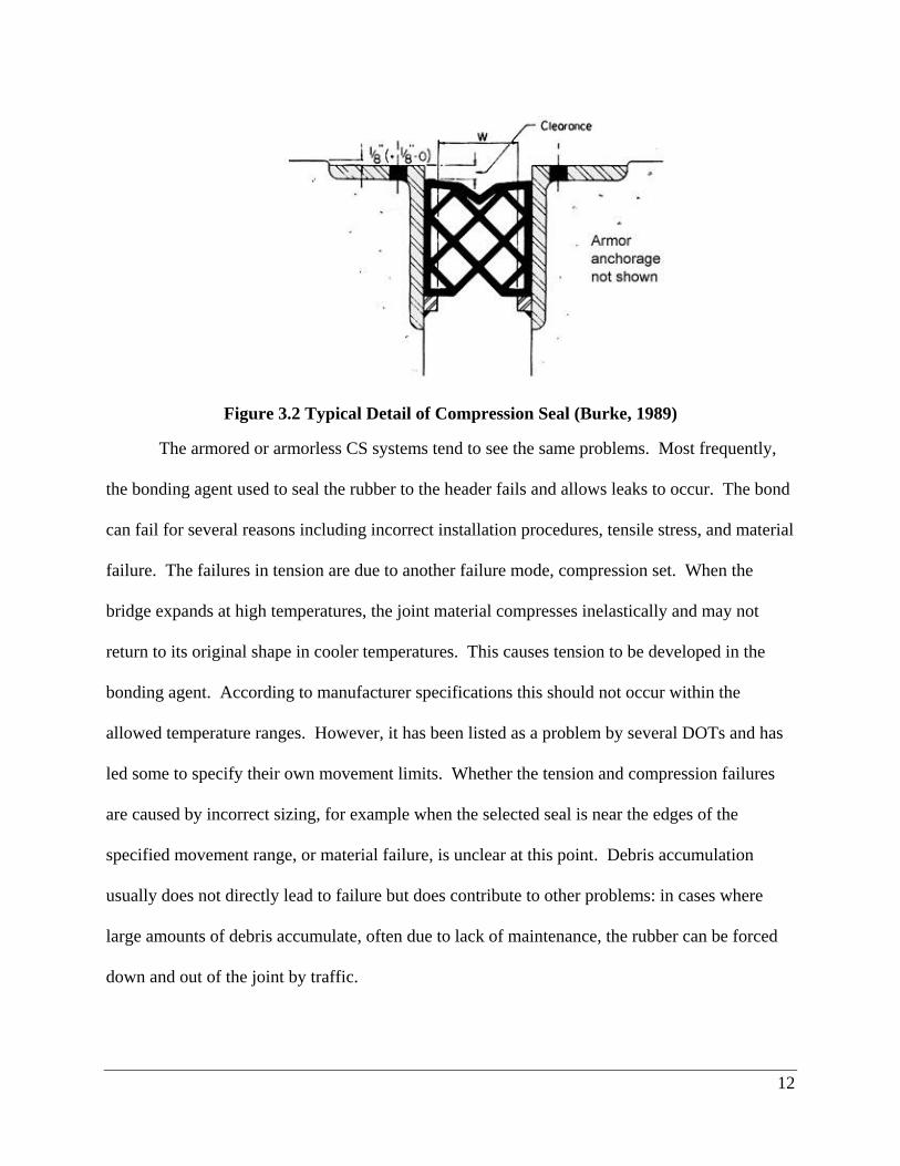
Figure 3.2 Typical Detail of Compression Seal (Burke, 1989)
The armored or armorless CS systems tend to see the same problems. Most frequently,
the bonding agent used to seal the rubber to the header fails and allows leaks to occur. The bond
can fail for several reasons including incorrect installation procedures, tensile stress, and material
failure. The failures in tension are due to another failure mode, compression set. When the
bridge expands at high temperatures, the joint material compresses inelastically and may not
return to its original shape in cooler temperatures. This causes tension to be developed in the
bonding agent. According to manufacturer specifications this should not occur within the
allowed temperature ranges. However, it has been listed as a problem by several DOTs and has
led some to specify their own movement limits. Whether the tension and compression failures
are caused by incorrect sizing, for example when the selected seal is near the edges of the
specified movement range, or material failure, is unclear at this point. Debris accumulation
usually does not directly lead to failure but does contribute to other problems: in cases where
large amounts of debris accumulate, often due to lack of maintenance, the rubber can be forced
down and out of the joint by traffic.
13
Once failure has occurred there are generally two repair options. If the failure only
occurs in the preformed rubber or sealant, then a partial replacement is necessary. The rubber
must be removed and the joint cleaned before the new compression seal can be placed. If the
rubber material has not failed but simply debonded from the header it is possible to reuse it, but
this is not recommended.
The following manufacturers of CS systems were found to be common among DOT
material specification requirements: D.S. Brown, and Watson Bowman Acme.
3.4PouredSilicone(PS)
Poured Silicone joints are manufacturer specific combinations of polymeric material that
often come as two components to be mixed on site. Although it is not absolutely necessary, most
manufacturers of these systems recommend the use of an elastomeric concrete header. After
curing, the header must be prepared with a primer before the silicone is applied. The material is
applied on top of a foam backer rod placed in the joint and may be self-leveling. Although each
manufacturer varies, recommended movement ranges typically vary from 0.25” to 1.5”. A
benefit of the PS over preformed silicone is that the same material can be used for different joints
sizes and does not need to be ordered separately. Furthermore, the PS may form around small
defects in the header and the headers do not need to be perfectly parallel. Because of the
relative ease and speed of installation, the PS has become very popular for rehabilitation and
joint replacements where a header already exists.

14
Figure 3.3 Typical Detail of Poured Silicone (Burke, 1989)
The most common mode of failure observed in PS systems is with the bond between the
silicon and the header. Normal deterioration, excess debris, excess tension, and poor installation
can all affect the quality of the bond. Installation procedures are particularly important as the
depth of the silicone greatly affects the stress experienced by the joint. If poured too thick, the
silicone will have a larger cross sectional area which requires more tension to deform. This
tensile force transfers directly to the bond and may exceed the ultimate strength. Manufacturer
recommendations and procedures should be followed to ensure this does not happen. If the
material is poured too thin it is more likely to rupture. Incorrect sizing of the joint can lead to
problems in compression where the silicone flexes upward out of the joint. Once this happens it
is susceptible to damage from vehicles. If debris is allowed to accumulate in the joint, traffic
may cause the PS to be forced down and break the bond or seal.
Repairing a PS joint after a failure of either the bonding agent or the silicone is relatively
easy. Partial or localized failures do not require replacing the entire joint because the silicone
will bond to itself. Therefore, after cutting out the failed material and cleaning the area, the new
material can be poured onto what already exists. If the entire joint fails, then most likely the

15
backer rod will have to be replaced and the joint re-poured. This process will require lane
closures but is quick and in most cases traffic can resume half an hour after pouring.
The following manufacturers of PS systems were found to be common among DOT
material specification requirements: Dow Corning, D.S. Brown, C.S. Behler, and Watson
Bowman Acme.
3.5PreformedSilicone(PFS)
Preformed Silicone joints are manufactured in predetermined sizes and are bonded to the
inside edge of the header. PFS do not require an elastomeric header but many systems have one.
A primer and bonding agent are used to seal the PFS to the header. Also, a backer rod is not
necessary but may make installation easier by keeping the seal in place before it has bonded.
The movement ranges are in general larger than the poured silicone, up to 4”. Presented in Figure
1.4 is a typical detail. The material may have a different shape or positioning depending on the
manufacturer and header material.
Figure 3.4 Typical Detail of Preformed Silicone
The failure modes are also very similar to the PS. Installation procedures are not as
critical but are still important to ensure that the bonding agent does not fail. If placed correctly,
the PFS should not rise above deck level, even when over compressed.
Concrete
Silicone Seal
Silicone Adhesive

16
To repair the PFS it is usually best to replace the entire joint seal. It is possible to splice
in a new a section of seal if only a small length needs to be repaired; however, splicing can be
unreliable and creates another area where the bonding agent may fail and cause the joint to leak.
The following manufacturers of PFS systems were found to be common among DOT
material specification requirements: R.J. Watson and Watson Bowman Acme.
3.6ClosedCellFoam(CCF)
Closed Cell Foam joints are typically made of a polyethylene copolymer that is extruded
into a rectangular shape. The exact composition and dimensions of the extruded material are
specific to each manufacturer. The CCF is capable of being used with concrete headers,
elastomeric concrete headers, or armored headers. This makes it particularly useful for
rehabilitations. A unique aspect of this type of joint is that it can be placed between vertical
surfaces such as barriers and curbs. This is accomplished by cutting and “heat welding” the
material to the desired shape, in the field. Movement capacities vary considerably depending on
the manufacturer, model, and geometry of the seal. According to some specifications the larger
CCF seals can accommodate nearly 5” of movement. However, DOT experience in the field has
indicated that such large movements are unrealistic and that a range of 1” to 3” is more
reasonable. This seal may also be useful on fixed ends and longitudinal joints. Furthermore,
although the manufacturers state that the joint is designed to take some tension (typically up to
25% of its original size), many reported failures are related to the bond agent or foam rupturing
in tension. This has led some DOTs to not consider tension capacity and treat the CCF as a
compression seal.

17
Figure 3.5 Typical Detail of Closed Cell Foam
The closed cell foam joint systems tend to see a combination of the failure modes typical
of compression and preformed silicone seals. The most common failure is with the bonding
agent and can be caused by numerous factors including poor maintenance, pushing out of the
seal by traffic, tension forces, improper installation, and poor header material. The foam
material may also fail due to puncture by debris, tension, or compression. The most common
issue causing poor performance or failure is improper installation. The procedure for mixing and
placing the bonding agent is particularly important because the bonding agent alone holds the
joint in place.
Repairing the CCF system is fairly simple. Small failures in the bonding agent may be
repaired by cleaning off the failed material and placing new bonding agent. A small failure in
the CCF may be repaired by splicing. The affected area should be cut out and cleaned before
replacing. In this case the bonding agent can also be used to seal the splice and connect the old
and new material. Some manufacturers recommend “heat welding” the two pieces together with
an iron. This can be difficult if welding more than one end because it becomes difficult to
properly place the material. Larger failures in the CCF require the entire seal to be replaced.
With regards to repair time, the CCF is mid-range. A total replacement or installation may take a
full day depending on the experience of the crew. Repairs or replacement of just the seal can be
done more quickly.

18
The following manufacturers of CCF systems were found to be common among DOT
material specification requirements: D.S. Brown, R.J. Watson, Polyset, and Watson Bowman
Acme.
3.7OpenCellFoam(OCF)
Open Cell Foam joints are new to the bridge joint market. The only manufacturer cited
by respondents is EMSEAL which has the BEJS system. This system is comprised of the foam
and silicone seal shown in Figure 3.6 as well as the epoxy adhesive, silicone sealant, and the
EMCRETE elastomeric header. Much like the CCF, the OCF can be used without the
elastomeric header on rehabilitations of existing bridges. The seal can also be used on vertical
surfaces such as curbs and parapets. EMSEAL offers pre-made 90° corner pieces that are
reversible to allow for upward or downward turns. If a unique angle is required, the material can
be cut and sealed using the silicone sealant. The movement range is from approximately 0.5” to
4”. The seal, when sized properly, acts as a compression seal and will not go into tension. Also,
the manufacturer states that compression set will not occur. Several test joints have been
installed and have not experienced issues with compression or tension failures.
Figure 3.6 Typical Detail of Open Cell Foam Joint

19
To this point, the joints currently installed have not experienced any failures. Most of
these test installations have been in place for two to three years, but modes of failure have been
speculated and could include: (1) improper sizing of the seal may lead to tension failures or over
compression of the material, (2) improper installation has the potential to weaken the bond,
especially if the epoxy adhesive is not applied correctly, and finally, (3) debris collection in the
joint may cause tearing of the silicone bellows or pushing out of the seal by traffic.
Repairing the OCF joint is similar to the CCF or PS joint. A damaged section can be cut
out and replaced with new material. In this case the silicone sealant would be used to bond the
new material to the existing seal. If the seal is too damaged to repair in sections, the remaining
material should be removed. The manufacturer’s procedures for standard installation should
then be followed.
As previously mentioned, the only cited manufacturer of OCF systems is EMSEAL.
However, investigation revealed Sealtite by Schul International is also an Open Cell Foam.
3.8StripSeal(SS)
A strip seal is a common type of armored joint that is still in use in many states. The basic
system consists of the seal which is a preformed neoprene rubber, and the steel extrusions, as
shown in Figure 3.7. The seal is secured by fitting the sides into a slot along the length of the
steel extrusions. The extrusions are attached to the bridge deck by anchors that are set into the
concrete, or, if used, an elastomeric header. Strip seals are usually for movements less than 4” or
5”.

20
Figure 3.7 Typical Detail of Strip Seal Joint (Burke, 1989)
The most frequent mode of failure is the pulling out or tearing of the seal, which causes
the joint to leak. In some cases debris can be pushed down and through the torn seal which
exacerbates the problem. In either case, the entire seal may need to be replaced because splices
are difficult to perform.
If the neoprene seal is damaged, it can be spliced but replacement of the seal is the best
option. As mentioned, splicing can be difficult and the manufacturer should be consulted. When
the steel is damaged to the point of failure, complete replacement of the joint is the most
effective option. While it is possible to repair small areas by cutting and welding, it is not
recommended, as the weld creates a new surface that is prone to fatigue. If the deck has failed
enough to cause failure of the joint, the header should be replaced.
The following manufacturers of SS systems were found to be common among DOT
material specification requirements: D.S. Brown and Watson Bowman Acme.

21
3.9ArmoredHeadersGeneral
The classic armored bridge joint consists of steel angles with anchors attached to the
insides of the legs. The angles may have slots or other features that allow a joint seal to be
attached. An example is shown in Figure 3.8. The anchors are set into the deck concrete to
provide support for the joint. Armored headers tend to be very strong and resistant to heavy
traffic. For installation, it is easiest to install the armoring when the deck is cast because the
anchors must be set in the concrete. There are no primers or other materials necessary for
installation beyond the normal requirements for concrete pouring.
Figure 3.8 General Detail of Armored Joint (Burke, 1989)
Deterioration, damage due to mis-alignment, and snow plow damage are the most
frequent problems with the armoring in armored joints. Over time, with exposure to water and
deicing agents the armor steel will corrode and may experience section loss; oxidation may also
occur underneath the angle and raise the edge above the deck surface. Misalignment of the
angles can result in unexpected forces acting on the steel. If the surface is not aligned with the
cross slope of the deck, traffic can induce bending forces and vibrations, causing the armor to
fatigue and potentially fail. Finally, if the steel angle protrudes above the deck surface, as a

22
result of improper installation or deterioration, it becomes susceptible to damage from snow
plows hitting it or damage due to heavy traffic. This can lead to damage to the joint, the header,
and the surrounding deck.
If steel armoring fails there are two options: splice in a new section or replace the entire
joint. Splicing is not necessarily the best option because this can create new planes for potential
failure of the joint.
3.10ElastomericHeadersGeneral
An elastomeric header is a concrete mixture with an added polymer binding agent that is
specific to the manufacturer. The most common bonder is epoxy. The binding agent makes the
concrete more flexible and durable than standard concrete. This reduces cracking, spalling, and
other problems commonly seen at bridge ends. It also makes the header more durable to impact.
However, it can lead to other problems, the most common being rutting under heavy loads.
Generally, to install an elastomeric header with a bare concrete deck, a block-out is formed when
the deck is poured. For decks with an overlay, the overlay is saw cut to provide space for the
placement of the joint. The area is cleaned and a primer placed on the bond surface. Finally the
material is poured and allowed to cure.

23
Figure 3.9 Typical Elastomeric Concrete Header
Deterioration and loss of material over time, such as raveling or rutting, are the most
likely problems. Plow damage is possible if the bridge is skewed at an angle that matches the
plow angle. During partial deck replacement, the material may be inadvertently damaged. In
most cases the material at the road surface is not crucial for structural integrity; however, the
material where the joint bonds to the header and where the header bonds to the deck must be
protected. If failure occurs, it may be possible to replace only the damaged area, however it is
likely the entire joint system will need to be replaced.
Overlay
Elastomeric Header
Concrete Deck

24

25
Chapter4 SummaryofResults
4.1ResponseRate
The online survey was sent to 28 DOT representatives. As mentioned in Chapter 2, the
number of representatives per state varied and the contact information can be found in the
appendices. There was at least one response per state, for a total of 24 responses. This
represents a response rate of 86 percent. Seven states had separate responses from both
maintenance and design divisions. The follow-up interviews were completed with 19 of the
representatives (repeated attempts to schedule a follow-up interview with some representatives
were unsuccessful). At least one representative per state was interviewed, except for DC. This
represents a follow-up rate of 68 percent. Five states completed an interview with both design
and maintenance personnel.
The surveys were a good starting point for each state and gave basic information
regarding joint performance and practices; however, the follow-up interviews proved to be more
useful and revealed considerably more information. In many cases, questions were not answered
fully in the survey, but when asked to expand on answers during the interview more information
was provided. It would be beneficial to complete the remaining surveys and follow-up interviews
to gain more detail.
4.2JointsUsedbyDOT
Presented in Table 4.1 is a table that outlines the joints used by each agency for new
construction and also for maintenance. A solid black bullet () indicates that it is used by the
agency, a circle with a backslash () indicates that it has been used but is being phased out or
the use is limited, a circle with an x () indicates that the agency specifically noted that the joint

26
is not used or has discontinued the use of the joint, and an empty cell indicates that the agency
made no reference to a particular type of joint. Presented in Figure 4.1 is a bar chart showing
the number of agencies that use a particular joint for new construction. A similar bar chart for
maintenance is shown in Figure 4.2.
Table 4.1 Joints Used by NEBPP DOT’s for New Construction and Maintenance
Joints Used for New Construction Joints Used for Maintenance
State APJ CS PS PFS CCF OCF SS APJ CS PS PFS CCF OCF SS
CT
DC
DE
MA
MD
ME
NH
NJ
NY
PA
RI
VT
Legend: - used by the agency, - limited use or is being phased out, - not used/discontinued, empty cell indicates no reference to the use of that joint type

27
Figure 4.1 Number of Agencies Using Joint for New Construction
Figure 4.2 Number of Agencies Using Joint for Maintenance

28
For new construction there is a clear preference towards Strip Seals. This is particularly
interesting because SS are an exclusively armored joint. In most cases, the DOTs that use SS
stated that these joints were preferred because of their durability and expected lifespans (Table
4.4). As noted in the joint description, armored joints such as the SS are more resource intensive
joints, requiring more time and money to repair once damaged. This preference suggests that
although snow plow damage occurs, it is either not frequent or not severe enough to cause
concern for many states. No states reported any type of cost analysis on armored vs unarmored
joints.
The Closed Cell Foam joints are only used in new construction by NY and for
maintenance by NY and DE. Several other states have used CCF joints on a limited basis
through test joints. To this point the states have seen mixed results. Some NY regions have been
pleased with the performance while others have seen frequent failures: NY respondents
speculated that this might be due to inconsistencies in installation across the different NY regions
and that not all installation crews may not be equally trained and experienced with CCF joints.
Unfortunately this difference, if any, was not captured through the surveys and interviews. The
problems may also be associated with incorrect sizing of the joint material. The interviews
indicated that this was believed to be the cause their problems. The spreadsheet mentioned in
Section 5.9 seeks to correct this problem.
Every joint type has been used in both new construction and for maintenance purposes
except the OCF. This is due to its recent entry into the marketplace as it has not had enough time
to be placed on approved materials lists. At this point, most states have put test joints in place or
are planning to do so in the near future. Massachusetts has installed several OCF joints and they
have performed well during the up to 4 years they have been in service. The OCF joints are not

29
listed as being used by those maintenance crews because they have not yet become the norm for
repairs.
The APJ, PS, PFS, and CCF joints are used for repairs and not design in some states. It
is expected that maintenance divisions will use a wider variety of joints than those used for new
construction. When performing repairs it is rare to experience the same conditions as new
construction unless the project is a complete bridge rehabilitation. Furthermore, maintenance
divisions are given more leeway when selecting joint types so that they may try new ones and
determine performance before those joints are approved. PS, PFS, and CCF joints may see
changes in the extruded shape or material properties that make it necessary to test them. In the
cases of joints such as the APJ, there is a long track record of performance and the materials,
although different between manufacturers, have similar properties. The surveys and interviews
did not indicate why joints such as the APJ were approved only for maintenance.
4.3DiscontinuedorLimitedJoints
Table 4.2 indicates the joints being phased out, discontinued, or no longer in use by the
DOT’s and the reason for their not using the joint. Seven states noted that they have limited the
use of or stopped using CS joints. The most common reason cited for this decision was frequent
failures due to pushing out of the seal. An exact cause of the pushing out was not known but
most believe it is due to debris buildup and could be prevented if more frequent maintenance and
clearing the joint of debris were performed.
There were no other joints commonly avoided by the states. In many cases DOTs did not
know exactly why their joints were failing, only that they failed more frequently than was
acceptable. It would be beneficial to track and record problem joints or joint types more closely
to determine exact causes.

30
Table 4.2 Small Movement Joints or Systems Discontinued by NEBPP DOT’s and Reason
State Joints/System Discontinued Reason
CT Compression SealsElastomeric Concrete with Armoring
Frequent failures Rutting
DC Phasing out Compression Seals Frequent pushing out of seal
DE None Indicated None Indicated
MA None Indicated None Indicated
MD Phasing out Compression SealsClosed Cell Foam
Difficult maintenance Compression set
ME None Indicated None Indicated
NH Limit Compression Seals Maintenance Phasing Poured Silicone
Tension failures Difficult installations
NJ Asphaltic Plug Compression Seal for new designs
Failure under heavy traffic Pushing out of seal
NY Any armored joints Plow damage Difficult to install
PA Phasing out Poured Silicone
Closed Cell Foams Compression Seals
Inconsistent installation Tested poorly
Frequent failures RI Compression Seals Frequent pushing out of seal
VT None Indicated None Indicated
4.4MethodsforMovementandSizingCalculations
Presented in Table 4.3 is the method used by the DOT’s to size the joint. For
determining movements, almost all of the DOT manuals exclusively reference the AASHTO
LRFD Bridge Design Manual section on thermal expansion. Several states included example
calculations that the engineer can follow. While not necessary this is helpful because it limits the
number of codes an engineer must look at and also provides a way to check their work. ME and

31
DC prefer a rule of thumb based on the expected expansion per length of span rather than
carrying out calculations (these ratios are based on the AASHTO thermal expansion equations
but are not as accurate as the movements one would calculate from mechanics). The reliance on
AASHTO codes was expected due to federal and state regulations.
Table 4.3 Methods for Sizing Joints
State Determining Movement Sizing Joint
CT AASHTO specifications Manufacturer
DC Movement per length of spanManufacturer with lower
limits
DE AASHTO specifications Manufacturer
MA AASHTO specifications Manufacturer
MD AASHTO specifications Manufacturer / spreadsheet
ME Movement per length of span Manufacturer / Experience
NH AASHTO specifications Manufacturer with lower
limits / started using spreadsheet
NJ AASHTO specifications Manufacturer
NY AASHTO specifications Manufacturer / moving
towards spreadsheet
PA AASHTO specifications Experience
RI AASHTO specifications Manufacturer
VT AASHTO specifications Manufacturer
When sizing the joint material most states rely on manufacturer specifications. In some
cases states have placed limits on these specifications that lower the acceptable movement range.
In general this was because more frequent failures were seen at the extreme ends of the ranges.
ME and PA have stated that they set their own movement ranges based on laboratory and field
tests. Three states (NY, MD, NH) have started using some type of spreadsheet to determine if a
joint will work for a given movement range. One consideration stood out as consistent with all

32
states, skewed bridges and the subsequent racking have a significant effect on joint performance.
There were varying methods to account for this problem. Some states set a lower maximum
movement when the bridge is skewed. Others choose a different joint type that has a more
flexible seal.
4.5JointLifespansandContributingFactors
Table 4.4 shows the average lifespan of each of the joints for new construction and also
replacement/rehabilitation as experienced and reported by the states. Note that the results
presented in the table should be considered typical - in some cases a joint may last significantly
longer. In the case of OCF joints, no average is available due to the limited number of joints that
have been installed. To this point it has not been placed on any new construction, therefore it is
impossible to know how long it lasts under ideal conditions.
Table 4.4 Typical Lifespan Experienced as Reported by the DOTs
Joint New Construction (yrs) Replacement/Rehabilitation (yrs)
Asphaltic Plug Joint 10 5
Compression Seals 15 6
Poured Silicone 7 3
Preformed Silicone 7 3
Closed Cell Foam 5 2
Open Cell Foam Unknown Test joints in place,
performing well after 3 yrs
Strip Seals 15 10
The lifespans shown above can be increased through regular maintenance of the joint.
Standard repair work such as patching spalled concrete or sealing gaps in the joint can be done
quickly and will make larger failures less likely. Clearing the joint of debris can also increase

33
the joint life. Any joints that use a rubber or polymeric seal benefit the most from debris
clearing. These joints rely on their bond with the side of the deck to stay in place and
accumulated debris causes excess tension to be developed at the bond. Many DOTs stated that
they cleaned joints regularly in the past but had since discontinued due to lack of funding and
available manpower. The DOTs that are still able to clean out joints on a regular basis noted that
it increased the service life of the joint seals.
When discussing joint failures, incorrect installation was noted by all DOTs as one of the
most frequent problems leading to failure. No DOTs were able to determine why this was so
often a problem. The use of state bridge crews as opposed to contractors did not eliminate the
problem. However, contractors were perceived to have more difficulty in delivering a
satisfactory installation. This problem could be due to several factors but has not been
researched further. Possible issues affecting proper installation are:
1. Time constraints from traffic and other concerns may limit a crew’s ability to follow all
of the procedures required by a manufacturer.
2. The joints may be installed in the wrong environmental conditions (temperature or
moisture). Most DOTs perform repairs during the summer months. Unfortunately this is
not the ideal time to repair joints because they close up in the hot weather and can be
difficult to access.
3. Contractors may not be keeping up to date with the appropriate procedures, specifically
when considering newer joint materials such as the two part poured silicones and the
closed cell foams. Although they are not DOT employees they may benefit from DOT
training about joint installations.

34
4.6DifferencesinHeaderMaterialBehavior
The use of elastomeric concrete headers has received mixed reviews on their performance
and durability. In most cases, they appear poorly suited for high traffic volume, particularly
when there are heavy truck loads. Due to its more flexible nature the elastomeric concrete tends
to rut. It was noted that the material does not always bond well with asphalt and is more
appropriate for bridges with concrete wearing surfaces. However, with an experienced crew the
material is faster and easier to install than standard concrete. It will set up quicker and allow
traffic to resume. This quality may prove useful for areas with limited work hours.
Armored headers are much stronger than elastomeric concrete. They do not rut and will
keep a clean edge for a long time. However, this durability comes at an expense: the armoring
costs more and takes more time to install. Also, proper installation is critical in achieving a long
service life. If the joint is not installed correctly, or if it is severely damaged by a plow, there is a
lot of time and effort that goes into replacing the steel.
Connecticut noted that they used elastomeric concrete to support armoring. This was
most likely an attempt to get the speed benefits of the elastomeric as well as the resiliency of the
armoring. This combination did not work well as the elastomeric still tended to rut in the area
between the steel and the bridge deck. The ruts allowed water to enter below the angles and
cause corrosion.
4.7TrackingJointPerformance
Every state is required by federal regulations to inspect bridges on a biennial basis.
Historically, each state has recorded inspection data as they saw fit, which has led to inconsistent
availability of information for all bridge elements, including joints. In most states joint
performance has only been well known by district engineers and the information has been
qualitative rather than quantitative. New Jersey is the only state that has implemented a database

35
for tracking joint performance. They require that the type of joint and its condition are recorded
every time one is inspected, repaired or replaced. The database has been examined for ease of
use and is believed to be more useful than standard inspection reports.
With the implementation of mandatory element-level inspections, there will be
AASHTO-defined elements for each joint type, and quantities (Linear Feet) recorded for each of
four condition states (Good, Fair, Poor, Severe). All DOTs will be required to performed
detailed element level inspections in the near future to conform to FHWA requirements. In
addition to element-level inspections, states will be required to have an asset management plan.
Therefore, theoretically, joint type and condition state data will be available and searchable
moving ahead.
4.8NeworUniquePractices
While spreadsheets are used by three states to size the joint, the one used by NY is
described here. This is because the most information is known about their spreadsheet and it was
also featured at the NYSDOT 2013 Bridge and Culvert Maintenance Expo and the 2013 NEBPP
Annual Meeting. The spreadsheet was developed for use with the CCF joints but may be
modified for other joint types. The spreadsheet, called the “Joint Calculator”, finds all of the
variables normally determined during joint design based on AASHTO region, material type, span
length, skew, existing temperature and existing joint opening. All of these values can be
determined through field measurements so that a bridge crew may size the joint on sight if
necessary. The calculator reports expected movement perpendicular and parallel to the span at
temperature extremes. The calculator can also determine if the joint material will experience too
much tension or compression based on the manufacturer specified maximum values of
compression and tension. The default assumption is that any tension is unacceptable so as to
36
avoid failure of the bonding material. Because the calculator has been developed with the CCF
in mind, it can also determine the appropriate width and depth of the material. Interested readers
may contact the maintenance division of NYSDOT for more information.
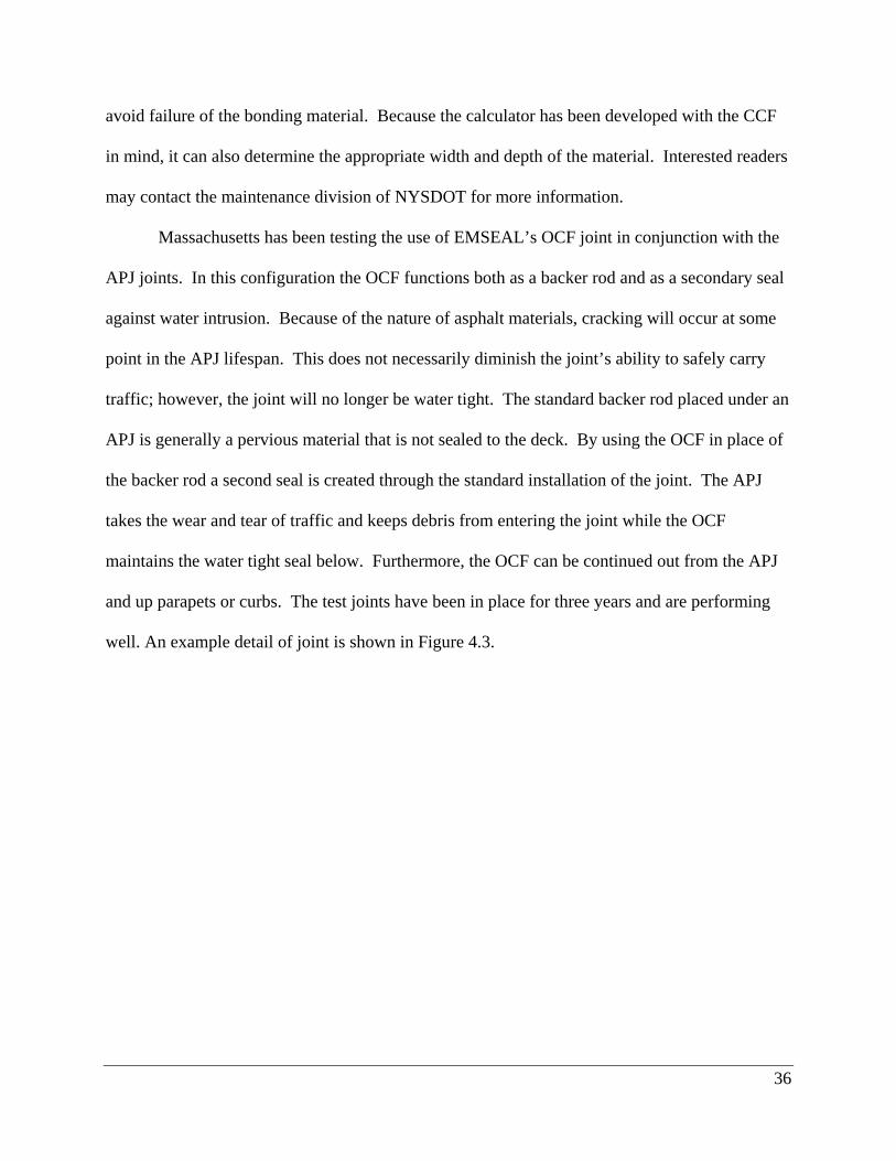
Massachusetts has been testing the use of EMSEAL’s OCF joint in conjunction with the
APJ joints. In this configuration the OCF functions both as a backer rod and as a secondary seal
against water intrusion. Because of the nature of asphalt materials, cracking will occur at some
point in the APJ lifespan. This does not necessarily diminish the joint’s ability to safely carry
traffic; however, the joint will no longer be water tight. The standard backer rod placed under an
APJ is generally a pervious material that is not sealed to the deck. By using the OCF in place of
the backer rod a second seal is created through the standard installation of the joint. The APJ
takes the wear and tear of traffic and keeps debris from entering the joint while the OCF
maintains the water tight seal below. Furthermore, the OCF can be continued out from the APJ
and up parapets or curbs. The test joints have been in place for three years and are performing
well. An example detail of joint is shown in Figure 4.3.

37
Figure 4.3 Example Schematic of APJ with OCF Backer Rod
Slab over backwall is not a new practice however several states noted that it is used in
place of or in conjunction with a small movement joint. In most cases this practice can be used
wherever a small movement joint can be placed. The benefit of using this approach is that
maintaining the joint seal is not as critical. Even if a joint begins to leak, the water will not affect
structural members because the water drains onto the subgrade or a sleeper slab. In general, this
is less detrimental to the bridge than having water drain onto beam ends or bearings. Of course,
this is more beneficial in new construction, but it can be used on existing bridges but may require
extensive reconstruction.
Training classes for expansion joints are not common practice among DOTs. ME offers
a “Bridge College 101” course that has short classes focusing on different aspects of a bridge. In
this course they have a class on bridge joints which can help inform maintenance crews and
others unfamiliar with expansion joints. While this is not a comprehensive course, it is a good

38
start. More knowledgeable crews will be better able to maintain and install joints. As more and
more work is contracted out and state bridge crews shrink it may also be prudent to make DOT
training courses available to contractors. These could help alleviate some of the aforementioned
problems with installation quality.

39
Chapter5 StateSummaries
Presented in this chapter is a summary of the data and information gathered for each
NEBPP DOT. This includes, for each, the joints in use for new construction and maintenance,
procedures and practices, past issues with joints, and anything new or unique being used by the
agency.
5.1Connecticut
When compared with other members of the NEBPP, the Connecticut BDM offers
significant guidance when selecting and designing expansion joints. In line with what most
DOTs specify, it begins by calling for the number of joints to be minimized through
superstructure geometry, such as the use of integral abutments. Furthermore, joints at abutments
should be placed behind the back wall so that joint failure does not affect the superstructure. It
also specifies some general guidelines for skew, curvature, and seismic effects, as well as the
applicable temperature range and corresponding movement for the state. The movement rates
are based on AASHTO specifications. Joint sizes are determined through manufacturer
specifications. The appropriate joint types for a given movement range are listed (see 5.1.1
below for specifics). There is also a brief section on longitudinal joints, which it should be noted
is uncommon in many bridge design manuals.
5.1.1JointsUsed
The most common joint used by the CT DOT for small movements is the APJ. It is used
for movements up to 1.5” unless there is a skew greater than 45°. CT DOT has noted that the
racking effects of large skews make the APJ deteriorate faster. The average expected lifespan of
the APJ is anywhere from two to ten years depending on traffic levels, skew, and quality of

40
installation. The most common failures seen are debonding of the APJ with the substrate,
cracking, tracking out, and rutting. These are often due to improper installation or poor material
quality. Maintenance procedures are limited to crack sealing or replacement of damaged
material. The overall evaluation of the APJ is satisfactory.
CTDOT noted that for movements up to 3” (just beyond the “small movement” range for
this study) or where the skew is greater than 45° they use either PS or PFS joints. Recently,
there has been a shift towards only PFS because they tend to perform better and are easier for
crews to install. The average expected lifespan for PS joints is 2 to 3 years. They have not used
PFS joints long enough to give an expected lifespan. Failures seen are typical of those noted in
the joint type descriptions. Notably, excess tension has caused the material to either rupture or
debond from the deck. Whether the excess tension is from improper design or installation has
not been investigated. Maintenance is limited to those methods mentioned in the PS and PFS
descriptions. The overall evaluation of the PS and PFS joints is satisfactory when designed and
installed correctly.
5.1.2ProceduresandPractices
The bridge design and maintenance divisions of CT DOT, follow the same general
procedures when sizing and placing joints. Maintenance has some leeway in selecting joint
types so that they may try new products. Connecticut does not have a separate manual for bridge
maintenance. They do have a Bridge Inspection Manual separate from the Bridge Design
Manual, which has some guidance in regards to joints.
Within the DOT, the departments of bridge inspection, maintenance, and design, are
separate and do not necessarily communicate information regarding the performance of joints.
Element level bridge data is collected by the inspection crews. Joint information such as type

41
and condition are recorded. Unfortunately, the recorded data is not searchable with respect to the
joints. At this point there is no easy way to track joint type and performance.
While bridges are inspected at least every other year, CT DOT does not perform
preventative maintenance or wash their bridge joints. All maintenance is done in response to a
problem. This is largely due to a lack of funding and available manpower. The majority of
funding goes towards fixing structural issues which are higher priority.
The approval process for use of a new joint has several steps. The new product
committee reviews material provided by a manufacturer or distributor. Then one or more test
sites are selected to install the new joint. The manufacturer or distributor is required to install the
trial joints to ensure proper procedures are followed. The test joints are left in place for one year
and then examined for failures or maintenance issues. If the joint performs well, it may be
approved for use.
5.1.3PastIssueswithJoints
The CT DOT has previously used compression seals. However, due to poor performance
and frequent failures they were discontinued. In a few instances, the compression seals
performed well. Those joints were left in place but if repair is needed they will most likely be
replaced by another joint. No investigation has been done into why those joints performed better
than their counterparts.
At one time, the DOT used elastomeric concrete to support the armoring on joints.
However the elastomeric material tended to rut and deform, thus exposing the armoring to plow
damage and weathering. They have since switched to only using standard concrete with armored
joints.

42
5.1.4New/Unique
CDOT is testing the new OCF joints by EMSEAL on two bridges as part of the joint’s
approval process. As of the follow-up interview they had not been evaluated for approval.
No special training beyond manufacturer information sessions is provided for joints.
When installing a joint, there may be an engineer on-site for consultation if one is available.
5.2Delaware
Delaware is currently in the process of rewriting their bridge design manual.
Unfortunately, the new material on expansion joints was not yet available. The older manual has
a moderate amount of guidance related to expansion joints but may be considered slightly out of
date to the current practices. It states that joints should be minimized and jointless bridges are
preferred. The joints specified for use are SS, PS, and CS. Example calculations are included, as
well as references to AASHTO specifications. Joint sizes are determined through manufacturer
specifications. A brief section on longitudinal joints is included. Delaware also has a bridge
maintenance manual which focuses on when and how to repair joints. The maintenance division
may use other joint types than those specified by design, in certain situations.
5.2.1JointsUsed
PS joints are used primarily on fixed ends but also for movements less than 1”. This joint
is not preferred unless the deck end surface is irregular or the SS will not fit. The failure modes
experienced and the maintenance practices are typical of those mentioned in the joint type
description. The expected lifespan of the PS is from 2 to 10 years depending on location and
quality of installation.
The CS is also used primarily on fixed ends or for movements less than 4” where a SS
cannot be used. Delaware has set slightly lower limits on the movement ranges than what the
manufacturer specifies because the joint did not always remain in compression. The expected

43
lifespan is also 2 to 10 years. However, this is more dependent on weathering as the seal may be
pushed out due to the buildup of debris.
SS are preferred for all movements less than 4”. The failure modes are typical of the
joint type, but rupture of the seal and separation of the steel from the deck were noted as most
frequent. If installed correctly, the expected lifespan is up to 20 years. The maintenance
procedures are typical of the joint type.
For maintenance purposes, many other joint types have been used in limited quantities
including APJ, CCF, and PFS. None of these have performed well enough to warrant a switch to
that type. These joints may last anywhere from 1 to 10 years depending on quality of
installation, location, and traffic level.
5.2.2ProceduresandPractices
The design and maintenance divisions follow the same procedures for sizing and placing
joints. However, selecting joint type is less standardized when performing maintenance or
reconstruction. The engineer may select any joint, provided that some research is done into how
it will perform. This is most likely why so many different types have been used for maintenance.
The design division has also started using a slab over backwall approach where possible to avoid
placing the joint on the bridge. This method is not mentioned in the manuals. More
standardization may be expected once the new bridge design manual is finished.
Bridge inspections are performed every two years as required, however no preventative
maintenance is performed. Inspection reports are filed in Pontis, but as is the case with most
states this does not capture information about joint type and performance. It is also not easily
searchable.

44
The approval process for new joints is not standardized. As mentioned, the engineer has
some discretion as to what joints are used provided some research is done. Testing may also be
performed through the materials testing department.
5.2.3PastIssueswithJoints
No joint types have been discontinued by DelDOT. As mentioned, they have set lower
limits on the movement ranges of CS to account for observed performance.
5.2.4New/Unique
The surveys and follow-up interviews did not reveal any unique or new practices.
5.3DistrictofColumbia
This discussion is based solely on the survey response and a review of DC’s manual; the
authors were unable to complete a follow-up interview with representatives from DC.
The District of Columbia does not have a separate bridge design manual available.
Bridge design standards are contained within their Design and Engineering Manual and include a
small section on bridge joints. They call for the number of bridge joints to be minimized.
Temperature considerations and movement calculations are referred to AASHTO. There is a
brief section for longitudinal joints. The only small movement joints listed for use are
compression seals and strip seals. Unlike most states, the movement ranges are specified in
terms of bridge length, not actual movement. Joint sizes are determined through manufacturer
specifications but with lower movement limits based on experience. Furthermore, the section
states a requirement that all bridge joints must be armored to protect the deck.
5.3.1JointsUsed
The design manual expresses a preference for CS joints when movement and geometry
permit. However, the survey response indicated that they prefer the strip seal. The movement

45
range for the CS is not explicitly stated in the manual. Inference shows that the useful range of
the CS is spans less than 250’ when the skew is less than 25°, or less than 65’ when the skew is
less than 35°. Frequent issues with pushing out of the seal were noted.
For large skews, strip seals are specified. They are expected to last for 15 years if
installed correctly. However, there have been frequent problems with leaking and the only repair
method is replacement. The overall evaluation of the SS is unsatisfactory.
5.3.2ProceduresandPractices
As previously stated, there is not a dedicated bridge design manual for DC. However,
they do have material specifications and design drawings for bridge joints. All design
procedures and calculations reference AASHTO specifications.
5.3.3PastIssueswithJoints
The survey response indicated that the DOT is moving away from compression seals. If
this is the case, the design manual has not yet been updated to reflect this change. The reason
noted for this change was frequent leaks and pushing out of the seal material.
5.3.4New/Unique
The exclusive use of armored joints is a rare requirement within the members of the
NEBPP. No explanation is given for this requirement other than that it protects the end of the
deck. As noted in the joint descriptions, armoring can make bridge maintenance considerably
more difficult.
5.4Maine
The bridge manual for Maine offers a moderate amount of guidance about expansion
joints. It states that they should be avoided whenever possible by using integral abutments and
slab over backwall. It specifies a general movement rate of 1.25” per 100’ of span length rather

46
than standard AASHTO equations. This is based on the expansion rate of steel. The two joints
listed for new construction are CS and SS. In the event of repair work, the engineer may select
another joint type. The manual recommends PS. These joints are considered temporary, only to
be left in place until a full replacement can be performed. Joint sizes are determined through
manufacturer specifications.
5.4.1JointsUsed
The CS is generally used for movements up to 2.5” and skews less than 25°. Maine has
created a table of appropriate movement ranges versus allowable skew for CS which is available
in Section 4.8.2 of their Bridge Design Guide. The limits set in the table are slightly lower than
those given by the manufacturer. This difference is based on experience with racking issues.
The failure modes and maintenance practices are typical of the joint type. The expected lifespan
is at least 15 years before a total replacement. Overall, they are satisfied with the CS.
The SS is used for movements up to 3” and skews less than 45°. The SS tends to perform
better than the CS on skews. The failure modes and maintenance practices are typical for the SS
joint. The expected lifespan is from 15 to 20 years before replacement is needed. They are
satisfied with the SS.
The PS is the joint type used for temporary repair work. It is not intended to be a long
term joint, therefore the expected lifespan is less than 2 years. However some have been
successfully left in place for 5 years. The most common issues seen are material rupture and
tension failures of the bond. Maine is satisfied with using the PS as a temporary solution.
5.4.2ProceduresandPractices
The design and maintenance divisions follow the same general practices in regards to
joints. The main difference is that the maintenance side is given a lot of flexibility in trying new

47
joints or methods that they believe show promise. At this point they have several test locations
for OCF, PFS, and APJ that are under review for future use.
The bridge inspection crews perform the standard inspections every two years and record
element level data in Pontis. Preventative maintenance is performed when possible. Also,
bridge maintenance crews wash out the joints every year and note any problems while they are
on site. Still, the data is not recorded in such a way that it is easily summarized and searchable.
The approval process is comparable to other states. The manufacturer or distributer fills
out an application with the DOT to be included in the approved products list. Once the DOT has
gathered information on the joint, a committee decides whether or not to move forward. They
may or may not choose to place test joints before approval.
5.4.3PastIssueswithJoints
No joint types have been barred from use. The current selections are based on
experience.
5.4.4New/Unique
The yearly washing out of bridge joints is unusual among the NEBPP members. Most do
not wash their bridges at all. Maine has found it is very useful for extending the life of CS and
SS joints.
A few OCF test joints have been placed but it is too early to determine how they are
performing. The DOT would also like to try using the OCF as a backer for the APJ system,
much like Massachusetts has done, but have not done so at this point.
“Bridge College 101” is a training course offered through the DOT which gives short
training sessions on different aspects of bridges, including joints. This course is useful for
maintenance and inspection crews, as well as contractors that lack experience.

48
5.5Massachusetts
The BDM for Massachusetts offers little to no guidance on expansion joints. Some
references are made to AASHTO and the section on thermal movement calculations is based on
AASHTO specifications. The only advice given is that joints should be avoided when possible
through integral abutments and continuous construction. Detail drawings and material
specifications are provided. Joint sizes are determined through manufacturer specifications. The
standard small movement joints used by Massachusetts are APJ and SS. These have been chosen
based on positive experience.
5.5.1JointsUsed
Asphaltic plug joints are used for movements less than 2” when the skew is less than 30°.
They have not limited use based on traffic volume. The failures experienced and repair methods
are typical for the joint type. An average lifespan can vary from 2 to 10 years depending on
location and quality of installation. What has dictated the use of APJ is that the repair cycle
tends to match the deck pavement cycle which makes conducting repairs easier. The deck repair
crew will mill the entire surface and replace the joint along with the pavement. Overall, they are
satisfied with the APJ.
For movements greater than 2” or where the skew is greater than 30°, SS are used. The
maintenance issues and practices are also typical of the joint type. Some issues with plow
damage have been noted due to the use of armoring on skewed bridges but not to an unusual
extent. Proper installation remains one of the most important factors in lifespan. The average
expected lifespan of a SS is at least 10 years. They are satisfied with the performance of SS
joints.

49
5.5.2ProceduresandPractices
As previously mentioned the BDM does not offer any significant guidance on the design
or selection of the joint. There is no separate maintenance manual. The follow-up interview
indicated that Massachusetts could benefit from a greater focus on the initial design stages and
selection process, before maintenance is an issue.
Bridges are inspected every two years as required but no preventative maintenance or
washing is done. There are a limited number of bridge crews and most maintenance efforts are
focused on structural issues. Inspection reports are compiled in Pontis; however, this is does not
capture any significant data on joint performance and is not easily searchable.
The process for approval for a new joint is comparable to other states. The DOT has a
materials research division that joint suppliers may apply to for approval. The maintenance
division has the ability to test new joints, but are currently satisfied with the APJ and SS.
5.5.3PastIssueswithJoints
The survey and follow-up interview did not note any significant issues with other joint
types beyond general dissatisfaction and discontinuation.
5.5.4New/Unique
One innovation was noted in the follow-up interview. The maintenance division
has decided to test the use of EMSEAL’s OCF as a backer rod for the APJ system in place of the
typical foam rod that accompanies the system. At this point, a few test joints have been placed
and have been performing well for 3 years. The difference noted when doing this is that the joint
will not leak as readily. The APJ surface takes the wear and tear and may not stay sealed. The
OCF maintains the seal and prevents leaks.

50
5.6Maryland
The Maryland State Highway Administration does not have a standard bridge design
manual. There are no written guidelines for selecting or designing expansion joints. Movement
calculations are based on AASHTO specifications. Standard detail drawings and material
specifications are available. Recently the design side has moved to a slab over backwall
approach for almost all bridges. For bridges under 70’, they do not have an expansion joint.
Over 70’ they use a PS joint. All new designs are being pushed towards this system. Previously,
they also used CS and some CCF. The method for sizing joints is based on a combination of
AASHTO, manufacturer specifications, and an excel spreadsheet.
5.6.1JointsUsed
The PS joint is the primary small movement joint for Maryland. It is used for movements
up to 2” but smaller movements are preferred. Older bridges with sliding plate joints are being
retrofitted to accommodate PS joints by cutting the plate. On new bridges, the leaks that affect
most bridge superstructures are not an issue due to its placement behind the backwall. The
failures they see are typical of the joint type. Most issues are believed to be due to improper
installation. The expected life of the PS is roughly 5 years. The overall evaluation of the PS is
satisfactory.
CS were previously used for new designs and are still maintained and replaced by
maintenance crews. There is however a shift towards using PS in place of these on existing
bridges. Difficulty making small repairs and maintaining the seal were listed as reasons for
switching. The failures and maintenance practices are typical for the joint type. On average, the
expected lifespan is 5 years. The DOT is dissatisfied with the CS.

51
5.6.2ProceduresandPractices
As mentioned, Maryland does not have a formal bridge design manual and therefore the
procedures for joint selection and design are not necessarily standardized. The maintenance and
design sides do communicate their findings and opinions well, which has led to the slab over
backwall approach.
Inspection crews record element level data in Pontis, as other states do, but there is no
data focused on joint performance. Also, the data is not summarized or searchable. Bridge
crews will sometimes clean joints if it is noted during inspection reports but it is reactionary, not
preventative.
The approval process for new joints goes through a DOT committee. The manufacturer
or distributer files their report and data with the committee. Then the joint is assigned to one or
more districts to test. After a period of time determined by the committee, the joint is evaluated
and may be approved.
5.6.3PastIssueswithJoints
The maintenance division has used some CCF in the past but has since discontinued it
use because of frequent issues with material failure. During hot summer months the joints would
experience compression set and subsequently fail when the joint expanded in the winter.
As noted above, the DOT is moving away from CS in favor of PS. They have not
discontinued use of the CS but are phasing it out at this point. The main reason for this is that
the PS is easier to repair.
5.6.4New/Unique
The slab over backwall approach is not a new method; however, its extensive use by
Maryland on all bridges in the small movement range is unusual. The switch to this method is
only 4 years old, so it is too early to tell if the bridges will perform better.

52
5.7NewHampshire
The New Hampshire Department of Transportation is in the process of updating their
bridge manual. The older edition from 2000 was initially reviewed. The follow-up interviews
provided a more up to date copy of what they will include about expansion joints. The older
manual states that joints should be avoided, especially over piers, near intersections, and at low
points. APJ, CS, and SS are the primary small movement joint types. The new sections give
more guidance about when each type is appropriate. Several design examples are also included.
The movement calculations are based on AASHTO specifications. The interviews noted the use
of a spreadsheet to accommodate for recent restrictions in movement ranges when sizing joints
(described below).
5.7.1JointsUsed
APJ are used for movements less than ¾” and skews less than 25°. This range has been
reduced from 1.5” due to frequent failures of joints over ¾” movement. Their use has also been
limited based on ADT and location on the bridge, to avoid high traffic areas. The failures and
maintenance issues are typical, but it was noted that they have had many problems with improper
installation. On a new joint the expected lifespan is from 5 to 10 years; however, on
maintenance work the expected lifespan drops to 1 to 5 years. Again, these depend on traffic
volume and quality of the installation. The overall opinion of the APJ’s performance is
“dissatisfied” and the joint is being phased out of new construction.
For movements up to 2” and skews less than 25°, CS are used. If the skew is from 25° to
30° the movement is limited to 1” due to racking concerns. Furthermore, when sizing the CS,
the DOT has set lower limits on the movement due to tension failures. The recent changes in CS
guidelines follow work done by Maine DOT. The manual explicitly states that any splices of the
seal material are to be avoided. Failure was most often caused by pushing out of the seal and

53
tension failures. On new construction or when completely replaced the CS can be expected to
last up to 15 years. They are dissatisfied with the ability to make small repairs on the joint.
For larger skews, the SS is used. It states that splices should also be avoided for the seal
unless absolutely necessary. The failure modes and maintenance practices are typical for the
joint type. The expected lifespan is roughly 15 years if installed correctly. The overall
evaluation of the SS is neutral.
In limited instances, the maintenance division has used PS and PFS. These joints have
been placed as temporary fixes before a total joint replacement. In general, it is believed the
joints did not perform well. The PS is being phased out by maintenance. Not enough data about
the PFS is available at this time.
5.7.2ProceduresandPractices
As previously mentioned, the bridge design manual is being updated to reflect the current
practices of the DOT. These changes arose from the experience of the maintenance division and
communication with the design division. Both divisions currently follow the same practices and
guidelines.
Bridges are inspected every two years as required and some data is recorded. The reports
do not capture details about the expansion joints, and they are not searchable. The maintenance
division also performs preventative maintenance and washing either yearly or every other year.
They clean out the CS and SS joints because it avoids debris buildup and push out failures that
are often seen with these joints.
The approval process for new joints is standardized. Manufacturers or distributors make
presentations to the bridge section. Then lab and field tests are performed. The length of time
for a test joint to be in place is at the evaluator’s discretion. If it is satisfactory, it is approved.

54
5.7.3PastIssueswithJoints
The only recent changes are the aforementioned limitations on APJ and CS joints.
Experience showed that APJ failed from larger movements as well as under heavy traffic. Also,
CS experienced problems due to incorrect sizing. The limitations seek to avoid tension failures
in the future.
5.7.4New/Unique
Yearly maintenance and washing of bridge joints was noted as uncommon among the
NEBPP. While other DOTs expressed a desire to clean their joints, most have not been able to
do so on a regular basis.
The use of a spreadsheet for calculation of acceptable movement ranges is not unique to
NH, however it is not yet the norm among the NEBPP. The calculations are different from those
done by manufacturers in that no tension is allowed to develop and the maximum compression is
lowered. This spreadsheet is similar to the one used by New York.
5.8NewJersey
The BDM for New Jersey offers a moderate amount of guidance for the engineer when
designing joints. For design calculations it references AASHTO specifications. Some notes are
made about what conditions to consider when selecting a joint. The preferred joint is a SS and
there is substantial information regarding when and how they should be used. It also states that
CS may be used but gives little information. The surveys indicated that CS are no longer used
for new construction. Joint sizes are determined through manufacturer specifications. The
manual also briefly touches on longitudinal joints. The bridge maintenance division indicated
that they also use PS and PFS for repair work.

55
5.8.1JointsUsed
Strip seals are specified for all movements less than 4”. The manual also states that in
general this correlates to spans less than 70’ and skews greater than 35°, as well as spans
between 70’ and 250’ and skews greater than 25°. The failures seen and maintenance practices
are typical of the joint type. The expected lifespan is from 10 to 15 years. The DOT is satisfied
with using SS.
Compression seals are also specified for movements less than 4” however they are more
likely to be used on fixed ends or longitudinal joints. The manual notes that racking can cause
issues but does not place a limit on skew. Instead it limits the parallel movement to 15% of the
seal width. There have been extensive issues with the seal pushing out which has led to the CS
no longer being used for new designs. However, the maintenance division continues to use and
replace CS when needed. The expected lifespan is from 5 to 10 years. The design side is
dissatisfied with CS, but the maintenance side is neutral.
For joint repairs PS may be used on movements of less than 3”. It is used primarily in
place of CS when the header cannot be completely smoothed, due to its ability to form to the
sides. There have been issues with tension failures, particularly with larger movements. The
expected lifespan is from 5 to 10 years depending on the quality of installation. The
maintenance division is satisfied with their use.
For repair work on movements between 3” and 4”, PFS may be used. They are not used
as frequently as the other joints. The failures seen and maintenance practices are typical for the
joint type. The expected lifespan is from 5 to 10 years.
5.8.2ProceduresandPractices
The maintenance and design divisions follow the same procedures for sizing and placing
joints; however, they do not necessarily select the same joint types. The design manual, while

56
recently published, does not reflect the change to only using SS. However, the lack of
significant information on CS within the manual may indicate the intention to stop using them.
While maintenance does not have a separate manual, they continue to use CS and also use PS
and PFS. These choices have been based on experience.
Bridges are inspected on the required two year cycle and necessary repairs are noted.
Inspections are recorded on a Work Order System where joint type and performance can be
captured. In general bridges are on a 10 year repair cycle but may also be repaired as needed. A
general lack of funding was noted as problematic for keeping up with proper maintenance.
The approval process for new joints is similar to other states. The manufacturer or
distributor makes a presentation to the materials testing department. Then one or more trial
joints are placed. After a minimum of one year the joint is evaluated. It may then be approved.
5.8.3PastIssueswithJoints
APJ have been used in the past, however there were frequent failures. No research was
done on the failures but the surveys indicated that heavy traffic was likely the cause. As
mentioned, the CS has seen issues with pushing out.
5.8.4New/Unique
New Jersey is the only state that has a system set up for recording and monitoring joint
performance. The Work Order System captures joint type, failure mode, and overall
performance. It does not record manufacturer.
5.9NewYork
The New York State Department of Transportation bridge design manual contains a
moderate amount of information regarding joint design and important considerations.
Calculations are referred to AASHTO. More information regarding sizing is contained in the

57
typical detail sheets. When possible continuous construction and integral abutments should be
used. There is a strong preference for armorless joints and interviews confirmed that there has
been a shift away from using any armored joints for small movements. This is because they
believe the armorless joints are faster to install and in general easier to repair. There is a brief
section which discusses longitudinal joints. There is also a section that describes important
considerations for maintenance of bridge joints. This is separate from the bridge maintenance
manual which focuses on procedures and specifications for repair of joints.
5.9.1JointsUsed
The CCF is used for movements less than 2.5”. NY DOT has noted several common
failure modes including bond loss, compression set, and loss of header material which leads to
leaks around the bond. There are also more issues when the bridge is skewed. The maintenance
procedures are typical of the joint type. However, replacements tend to occur in warm months
and the joints may not be sized correctly at the time. The expected lifespan is up to 5 years for
the seal and 10 years for the header. If there are no issues with installation they may last longer.
Overall, they are dissatisfied with the CCF.
PS is used for movements up to 1.75”. The failure modes seen are typical for the joint
type. It was noted that improper installations are frequent with inexperienced crews. The
maintenance procedures are typical for the joint. The expected lifespan is up to 5 years. They
are dissatisfied with PS joints.
In cases where movements are too large for the PS but a CCF is not practical, a PFS joint
may be used. The failures and procedures noted were typical of the joint type. The expected
lifespan is up to 10 years but many fail before this point if not properly maintained. The overall
evaluation of the PFS is neutral.

58
The maintenance division has used APJ in some cases. However, they noted that it does
not bond well with elastomeric concrete and will fail suddenly. They have not seen rutting. If
installed correctly on standard concrete the APJ lasts roughly 6 years. The maintenance
practices are typical for the joint. For its limited use, they are satisfied with the APJ.
5.9.2ProceduresandPractices
The bridge design procedures, as they relate to expansion joints, are currently being
revised. Previously joints were sized primarily from manufacturer specifications. Bridge
maintenance has developed and has been using a spreadsheet, presented at the 2012 Annual
NEBPP meeting, which seeks to eliminate tension and over compression of the seal materials.
This spreadsheet may soon be included as part of design procedures as well.
NY inspects bridges every two years as required and records issues. However, there are
several different databases that have been used. They are planning to consolidate this data in the
future by switching to one system. At this time, the data captured does not reflect joint
performance.
In the past bridge crews washed out joints annually. In recent years work force
reductions have reduced the frequency of washing. Preventative maintenance is still performed
when possible, but this has also seen a decline.
The approval process for new joints is similar to other states. The manufacturer or
distributor makes a submission to the DOT for inclusion in the approved materials. Lab testing
is performed as well as a demonstration. Then a test joint is installed and evaluated after 2 years.
The joint may then be approved.

59
5.9.3PastIssueswithJoints
As previously mentioned, NY has stopped using armored joints. They believe that the
armoring is too maintenance intensive and time consuming when compared to elastomeric or
standard concrete headers.
5.9.4New/Unique
The aforementioned spreadsheet is a recent development for the design division. This
differs from some of the spreadsheets used in other states in that it considers both tension and
over compression. NH is using a similar spreadsheet. Using calculated results often results in an
acceptable movement range that is considerably less than those specified by manufacturers. The
maintenance division has noted that they see far fewer failures of the CCF joint when following
the new method. More information about this spreadsheet is included in section 4.8.
5.10Pennsylvania
The BDM for Pennsylvania has an extensive section on the design and selection of
expansion joints. In particular, it focuses on the contributions of rotation and skew to joint
movement. The manual states that the number of expansion joints should be reduced by using
continuous construction and integral abutments. It also makes an unusual stipulation that all
joints must be rated for at least 3” of movement regardless of the actual movement. SS and CS
are listed as the only joints to be used on new construction, with a preference for SS. There is
also a table that gives maximum movement ranges, based on skew angle, for each joint type.
This table is based on testing and experience.
The maintenance division also uses APJ and PS joints. There is a separate maintenance
manual that focuses on repair and replacement procedures for bridge crews.

60
5.10.1JointsUsed
SS are the preferred choice for any joints with a movement less than 4”. The most
frequent failure modes are rupture and pushing out of the seal. These are both due to debris
buildup. The repair methods are typical of the joint type; however, there has been some
difficulty when replacing the seal if the joint is not open enough. The expected lifespan is at
least 15 years. The overall evaluation of the SS joint is satisfactory.
The CS has the same maximum movement of 4” but varies with skew. Furthermore they
must be unarmored, have an ADTT less than 100, and a minimum movement of at least 1”. The
joint frequently fails through pushing out and debris buildup. The maintenance division
indicated that this has led them to stop using the CS, however the design division did not reflect
this change. The maintenance practices are typical for the joint type. The expected lifespan of
the CS is from 2 to 10 years and is largely dependent on how fast debris accumulates. In general,
the DOT is not satisfied with the CS.
PS and APJ are used as temporary fixes for joints when a full repair is not possible. They
most often experience failures due to improper or poor installation. The PS sees more frequent
failures than APJ and is being phased out. Neither joint is expected to last more than 5 years.
5.10.2ProceduresandPractices
The design and maintenance division follow the same general procedures when selecting
and sizing joints. Recently the design side has shifted to using slab over backwall whenever
possible. As mentioned the bridge maintenance manual focuses on repair procedures for the
bridge crews and contractors to follow. It does not review selection or sizing methods.
As required, bridges are inspected every two years and maintenance issues are recorded.
This data does not capture joint performance information. In recent years the PS joints have
been specifically targeted for performance reports because of their frequent failures. Minimal

61
preventative maintenance is done and joints may be washed out if inspection reports determine it
is necessary. The interviews noted that more frequent washing may help prevent joint failures
but they lack the necessary resources and time.
The approval process for joints is similar to other states. The new product division
receives information about a joint from the manufacturer or distributor. The joint is then tested
in one or more districts and performance is tracked. After a minimum of 2 years, the joint is
evaluated. It may then be approved for use.
5.10.3PastIssueswithJoints
As mentioned, the PS joint has seen frequent failures and the DOT is moving away from
using them altogether. CCF joints have been tested in the past with mixed results. It was decided
that they should not be used. Elastomeric headers have generally performed poorly and may fail
suddenly. They may still be specified but they are not preferred.
5.10.4New/Unique
Several OCF test joints are in place but have not been evaluated. If they perform well
they may take the place of PS joints for repairs.
5.11RhodeIsland
The Rhode Island bridge design manual offers minimal guidance on design and selection
of expansion joints. Most of the section refers to AASHTO specifications for details. It states
that the number of joints should be minimized. Any joints with a movement less than 3/8” are
considered to be fixed joints. For larger movements APJ and SS are specified. Joint sizes are
determined through manufacturer specifications.

62
5.11.1JointsUsed
For movements less than 1” and with a skew less than 10° the RI DOT uses APJ. They
may also be used on fixed joints with a skew less than 30° if the designer feels it is warranted.
However the representative noted that this limit has been exceeded in many cases due to this
joint’s easy design and installation. The average lifespan expected is four to five years
depending on the traffic level and installation quality. Low traffic levels have extended the life
of the joint to ten years or more in some cases. The failure modes seen by RI are typical of the
joint type. Their maintenance and repair are mostly limited to crack sealing or replacement. The
overall opinion of the APJ is neutral.
The bridge design manual specifies SS for movements from 1” to 5” or for skews greater
than 10°. An average expected lifespan for this type has not been determined. Still, the DOT
believes they are performing adequately. The failures and maintenance issues with the joint are
typical. The DOT does not perform any maintenance on the joint other than replacement due to
lack of manpower and time.
5.11.2ProceduresandPractices
In general, the bridge design and maintenance sides have the same procedures in terms of
joints. However, as with other states, the maintenance division is given some leeway to
investigate new materials on their own. There is not a separate bridge maintenance manual.
Although some joints are replaced by DOT maintenance crews, repair jobs are often bid out to
contractors. This is due to the lack of available manpower. In these cases replacement joints are
usually sized and selected using existing plans. However, in some cases a design engineer may
be consulted if the condition of the bridge has changed.
Bridges are inspected every two years but no washing or preventative maintenance is
performed. This is due to a lack of funding and manpower for the inspection crews. During

63
inspection, element level data such as leakage and failures are recorded in Pontis. This data is
searchable in terms of joint type or condition but not manufacturer.
The approval process for new joint materials is not necessarily standardized. New joints
go through application and testing with the Materials Department of RI DOT. They may be
tested through the materials department before approval.
5.11.3PastIssueswithJoints
In the past, CS were used as expansion joints but have since been limited to only
longitudinal joints, if at all. This joint type frequently experienced failure by pushing out of the
seal. While it has not been researched, this is most likely due to lack of cleaning and buildup of
debris.
5.11.4New/Unique
The survey and subsequent interview did not reveal anything unique to RI.
5.12Vermont
The design manual for Vermont has minimal information regarding expansion joint
design. For requirements and calculations the manual refers to AASHTO specifications. Most
information regarding the joints used by Vermont is contained in the standard detail drawings.
This information pertains mostly to construction and installation procedures.
At this time, not all follow-up interviews have been completed and the following
information is not complete.
5.12.1JointsUsed
APJ are used for movements up to 1”. The maintenance issues and failures seen with the
APJ are typical of the joint type. The expected lifespan is roughly 7 years depending on location
and quality of installation. The overall evaluation of the APJ is satisfactory.

64
For movements less than 3 inches, they use the Vermont Square Plate joint. This joint
has not been included in the general descriptions because this is the only case of its use. The
basic design is an open joint with a trough underneath. More information can be found in the
standard drawings online. Vermont has been very pleased with the performance of this joint,
which has dictated its use.
5.12.2ProceduresandPractices
Bridges are inspected every two years as required and element level data is recorded in
Pontis. In 2012, they began recording more information specific to joints so that performance
can be tracked.
5.12.3PastIssueswithJoints
Other joints have been tested in the past but have not warranted a shift in which types are
used.
5.12.4New/Unique
The aforementioned Vermont Square Plate joint is unique to this state. For more
information, please refer to the VTrans website for the detail drawings.
(http://www.aot.state.vt.us/CADDhelp/DownLoad/Details/Structures/StructuresDetails_Set.pdf)

65
Chapter6 SummaryandConclusions
6.1SummaryofReport
The member states of the NEBPP have varying experiences, opinions, and procedures
related to the design and maintenance of small movement bridge expansion joints. This research
attempted to determine commonly used expansion joints, collect information on the performance
of those joints, and examine the current state of practice of joint design and maintenance within
the NEBPP. This was done through a review of pertinent literature, as well as surveys and
interviews of DOT engineers and maintenance personnel.
The literature review revealed that no studies had been performed to look at the
performance of small movement expansion joints on a large region or national basis. A few
studies of a similar nature were conducted that focused on the joints in a particular state or a
specific joint. Nevertheless, these reports provided a starting point for this research as well as a
blueprint for how to proceed. The literature also covered the DOT design manuals of the
NEBPP. These manuals gave a baseline of the standards and practices within each state. The
joints common among the NEBPP are the asphaltic plug joint, compression seals, poured
silicone seals, preformed silicone seals, closed cell foams, open cell foams, and strip seals. More
detail on each of these joints is included in Chapter 3.
Online surveys and follow-up interviews of DOT engineers and maintenance personnel
were conducted to get a more up to date and detailed summary of DOT design practices than
what was provided in the design manuals. In many cases the manuals did not have extensive
sections dedicated to joint design. Several were also in the process of being updated. The
surveys and interviews also provided information regarding bridge maintenance practices. The

66
majority of states do not have a manual dedicated to bridge maintenance and therefore the
surveys and interviews were the only way to collect information. Chapter 4 summarizes the
major findings of the surveys and interviews. A detailed discussion of each state is included in
Chapter 5.
6.2Conclusions
The key conclusions that can be drawn from this study are the following:
1. There is no single preferred joint in use in the northeast for new construction. It is clear
that no single joint has performed well enough to be uniformly adopted by all DOTs.
The strip seal is the most popular, but it is still only used by just over half of the NEBPP
members in new construction. On the other hand, the compression seal is not being used
or is being phased out of use by almost all DOTs.
2. A variety of joint types are used for repair and replacement in the northeast, but again no
one single joint has become the preferred joint for repair. The most popular are the
asphaltic plug, strip seal, and poured silicone.
3. Design divisions tend to choose older joint types while maintenance divisions have been
more progressive in their choices, which may be due to their ability to purchase products
directly.
4. The majority of NEBPP states are sizing their joints based on manufacturer specifications
and past experience. A few states have recently adopted a more rigorous calculation
based method.
5. There is no standardized method for tracking the performance of expansion joints. In
most states the only data related to joints is found in bridge inspection reports. The

67
information is inconsistent, rarely quantitative, not searchable, and is therefore
insufficient to evaluate the long term performance of joints.
6. Preventative maintenance and cleaning can significantly increase the life of joints,
particularly those with neoprene or rubber seals. The lack of cleaning and other
preventative maintenance practices by most DOTs may be adversely affecting long term
performance of their joints.
7. The DOTs that have determined their own movement ranges for joints based on lab or
field testing have seen better results and less frequent failures. Other DOTs may benefit
from their research or performing new testing.
8. As is the case with most bridge maintenance issues, the problems experienced with
expansion joints can be tracked back to a lack of funding. Better funding can provide
extensive material testing, larger bridge crews, more frequent and consistent
maintenance, and more extensive repairs.
6.3FutureWork
Below are several issues for potential future work or research:
1. Future research may focus on analyzing the bridge inspection reports of each state.
While current reports may not be a complete record, they do contain some performance
information. However, element level inspections will provide more information for
future studies. The element level inspections will enable the States to systematically track
the performance and life cycle costs of the joints. The system should include a database
so that the information can be gathered, searched, and analyzed. New Jersey has just
recently implemented a process for collecting and storing joint information, which may
serve as a model for other DOTs.

68
2. The report by Purdue University (Chang and Lee, 2001) suggested the use of warrantees,
beyond those provided by manufacturers, to guarantee work. The NEBPP members may
see higher quality installations if the contractor is required to include a warranty with
their work.

69
References AASHTO. (2007) Maintenance Manual for Roadways and Bridges. American Association of
State Highway and Transportation Officials. Washington, D.C. (Section 3.1.3.13) Burke, Martin P. (1989) NCHRP Synthesis of Highway Practice 141: Bridge Deck Joints.
September, 1989. Transportation Research Board, National Research Council. Washington, D.C.
Caicedo, J. M., Rizos, D., Wieger, G., Ziehl, P. (2011) Simplifying Bridge Expansion Joint
Design and Maintenance. October 19, 2011. Department of Civil and Environmental Engineering, University of South Carolina. Columbia, SC. (Report No. FHWA-SC-11-03)
Chang, L. M., and Y. Lee. (2001) Evaluation and Policy for Bridge Deck Expansion Joints.
Publication FHWA/IN/JTRP-2000/01. Joint Transportation Research Program, Indiana Department of Transportation and Purdue University, West Lafayette, Indiana, 2001. doi: 10.5703/1288284313206.
Connecticut Department of Transportation (2003). Bridge Design Manual. Connecticut
Department of Transportation. Newington, CT. (Division I, Section 10) Connecticut Department of Transportation (2001). Bridge Inspection Manual Version 2.1.
Connecticut Department of Transportation. Newington, CT. (Section 6.1.12) Delaware Department of Transportation (2005). Bridge Design Manual. Delaware Department of
Transportation. Dover, DE. (Section 5.3.5) Delaware Department of Transportation (2012). Bridge Manual 201:Bridge Anatomy,
Preventative Maintenance, Bridge Repair and Rehabilitation. Delaware Department of Transportation. Dover, DE. (Sections A.2.2.4.1, B.3.2, C.1.3.1)
District of Columbia Department of Transportation (2009). Design and Engineering Manual.
District of Columbia Department of Transportation. Washington, D.C. (Section 18.9) Maine Department of Transportation (2003). Bridge Design Guide. Maine Department of
Transportation. Augusta, ME. (Sections 4.8 and 10.4) Malla, R. B., Shaw, M. T., Shrestha, M.R., Boob, S. (2006) Sealing of Small Movement Bridge
Expansion Joints. University of Connecticut Department of Civil and Environmental Engineering and The New England Transportation Consortium. (Project No. 02-6)
Malla, R. B., Shaw, M. T., Shrestha, M.R., Boob, S. (2011) Sealing of Small Movement Bridge
Expansion Joints – Phase 2: Field Demonstration and Monitoring. University of Connecticut Department of Civil and Environmental Engineering and The New England Transportation Consortium. (Project No. 02-6 Phase 2)

70
Massachusetts Department of Transportation (2009). LRFD Bridge Manual. Massachusetts
Department of Transportation. Boston, MA. Mogawer, W. S., Austerman, A.J. (2004) Evaluation of Asphaltic Expansion Joints. University
of Massachusetts Dartmouth Department of Civil and Environmental Engineering and The New England Transportation Consortium. (NETC 99-2)
New Hampshire Department of Transportation (2000). Bridge Design Manual Part 1: Design
Guidelines & Plates. New Hampshire Department of Transportation, Bureau of Bridge Design. Concord, NH. (Section 641)
New Jersey Department of Transportation (2009). Design Manual for Bridges and Structures
Fifth Edition. New Jersey Department of Transportation. Trenton, NJ. (Section 21) New York Department of Transportation (2008). Bridge Manual: US Customary Edition. New
York Department of Transportation. Albany, NY. (Sections 5.5 and 22) Pennsylvania Department of Transportation (2012). Design Manual Part 4: Structures.
Pennsylvania Department of Transportation. Harrisburg, PA. (Section 14) Pennsylvania Department of Transportation (2012). Bridge Maintenance Manual. Pennsylvania
Department of Transportation. Harrisburg, PA. (Section 14) Purvis, Ron. (2003) NCHRP Synthesis of Highway Practice 319: Bridge Deck Joint
Performance. Transportation Research Board, National Research Council. Washington, D.C.
Rhode Island Department of Transportation (2007). Rhode Island LRFD Bridge Design Manual.
Rhode Island Department of Transportation. Providence, RI. (Section 14) Vermont Agency of Transportation, Structures Section (2010). VTrans Structures Design
Manual. Vermont Agency of Transportation. Montpelier, VT. (Section 14)

71
Appendices

72
A.1DOT(Survey)Contacts
DOT First Name Last Name Work Phone # Email Address
CT Dave Hiscox 860-594-2626 [email protected]
DC Don Cooney 202-671-4681 [email protected]
DC Yared Tesfaye 202-671-4687 [email protected]
DE Michael Gettings 302-760-2754 [email protected]
DE Calvin Weber 302-760-2324 [email protected]
ME Dave Sherlock [email protected]
ME William Doukas 207-624-3424 [email protected]
MA Mohammed Nabulsi 508-929-3849 [email protected]
MD Joe Navarra 410-545-8 315 [email protected]
MD Jared Ferber [email protected]
MD Rod Thornton 410-545-8388 [email protected]
NH Doug Gosling 603-271-3667 [email protected]
NH Tim Boodey 603-271-3667 [email protected]
NH Angela Hubbard 603-271-2731 [email protected]
NJ Gerald Oliveto 609-462-6229 [email protected]
NJ Eddy Germain 609-530-2561 [email protected]
NY NYSDOT Bridge Maintenance Engineer
NY Rick Hunkins 315-782-4473 [email protected]
NY Patrick Barnes 518-485-9387 [email protected]
NY Harry Young 845-437-3378 [email protected]
NY Erica Westhius [email protected]
NY Pete McCowan 518-485-1148 [email protected]
PA Lou Ruzzi 412-429-4893 [email protected]
PA Ralph DeStefano 814-696-7180 [email protected]
RI Keith Gaulin 401-222-2053 x4068 [email protected]
VT Wayne Symonds 802-828-0503 [email protected]
VT Bill Sargent 802-828-2699 [email protected]
VT Pam Thurber 802-828-0041 [email protected]

73
A.2OnlineSurvey
NEBPP Initial Survey Q14 The Northeast Bridge Preservation Partnership is conducting a research study on the current state of practice and past performance of small movement (< 1.5") expansion joints. You have been identified as a person who has some job responsibility related to the design, maintenance, or repair of these types of joints. We would appreciate it if you would complete the following survey.PLEASE NOTE: If you do not finish the survey and close the window your answers will not be saved. You cannot go forward or backward and this is the only page of the survey. If you have trouble and are unable to submit your answers please email Micah Milner at [email protected]. Q17 Please provide:
Name: (1) Job title (2) Agency/affiliation (3) Preferred email address (4) Preferred phone number (5)
Q13 Please select the state or district in which you work: Maryland (1) Delaware (2) Pennsylvania (3) New Jersey (4) New York (5) Rhode Island (6) Connecticut (7) New Hampshire (8) Vermont (9) Massachusetts (10) District of Columbia (11) Maine (12) Q6 What is your primary job function in relation to small movement expansion joints (multiple selections allowed)? Engineering/design (1) Maintenance planning (2) Maintenance field work (3) Other (4) ____________________ Q7 How many years of experience do you have with the design/maintenance/repair of small movement expansion joints? ______ Click to write Choice 1 (1)

74
Q9 What system or systems does your agency currently use for small movement expansion joints? Please provide as much detail as possible. Q18 What is the typical service life you are achieving with your current systems? Q20 How satisfied are you with the performance of the current system(s) you are using? Very Dissatisfied (1) Dissatisfied (2) Neutral (3) Satisfied (4) Very Satisfied (5) Q19 What type of maintenance practices do you employ? Q11 Please describe any problems or causes of failure that you have observed with small movement expansion joints. Q10 If there are systems that you used in the past but no longer do, please describe them and why you longer use them. Q15 Do you keep detailed records/inspection reports about past performance? Q12 How does your agency determine widths for small movement expansion joints? What is the protocol/procedure for determining the width? Q16 Would you be able to provide copies of material specifications that you currently use? Q21 Would you be able to provide the protocol and a few examples of design calculations for determining the joint width? Q23 This is the end of the survey. Once you hit the button below you will not be able to go back and your answers will be submitted.

75
A.3SurveyResponses
Initial Report Last Modified: 06/20/2013

76
1. Please provide:
Name: Job title Agency/affiliation
Preferred email address Preferred phone number
Michael Gettings
Bridge Design Resource Engineer
DelDOT [email protected] 302‐760‐2754
Calvin Weber
Bridge Maintenance Engineer
Delaware DOT [email protected] 302‐760‐2324
Angela Hubbard
Project Engineer
NHDOT Bridge Design
[email protected] 603‐271‐2731
Doug Gosling
Bridge Maintenance Engineer
NHDOT [email protected] 603.271.3667
William P. Sargent
Bridge Maintenance Manager
VT Agency of Transportation
[email protected] 802‐828‐2699
Timothy Boodey
Maintenance and Construction Engineer
New Hampshire Dept of Transportation
[email protected] 603‐271‐3667
Eddy Germain
Supervising Engineer
NJDOT [email protected] 609‐530‐2561
Pam Thurber
Bridge Mgmt/Insp Engineer
VTrans/Structures
[email protected] 802‐828‐0041
William Doukas
Sr. Structural Engr, Bridge Maintenance
Maine Dept of Transportation
[email protected] 207‐624‐3424
Joe Navarra Team Leader
Maryland State Highway Administration
[email protected] 410‐545‐8315
Rod Thornton
Chief Structures Remedial Engineering Division
Maryland State Highway Administration
[email protected] 410‐545‐8388
Peter McCowan
Civil Engineer III (Structures)
NYSDOT [email protected] 518‐485‐1148
Harry Young
assistant Bridge Maintenanc
NYS DOT [email protected] 845‐437‐3378

77
e Engineer
Patrick Barnes
Regional Bridge Maint. Engr.
NYSDOT Region 1 [email protected] 518‐485‐9387
Ralph DeStefano
District 9 Bridge Engineer
PennDOT [email protected] 8146967180
David Hiscox
Trans. Supervising Engineer
CT Dept of Transportation
[email protected] (860) 594‐2626
Ricky D. Hunkins
Regional Bridge Maintenance Engineer
NYSDOT [email protected] 315‐782‐4473
Wayne Symonds
Structures Design Eng.
VTrans [email protected] 802 828 0503
Mohammed Nabulsi
District Bridge Engineer
MassDOT [email protected]
(508) 929 3849
Lou Ruzzi District Bridge Engineer
PennDOT‐District 11‐0
[email protected] 412‐429‐4893
Keith Gaulin
Principal Civil Engineer
Rhode Island Department of Transportation
[email protected] 401‐222‐2053x4068
Yared Tesfaye
Bridge Managemen Engineer
DC DOT [email protected] 2026714687
Gerald Oliveto
Senior Engineer
NJDOT [email protected] 609‐462‐6229
Statistic Value Total Responses 23

78
2. Please select the state or district in which you work: # Answer
Response % 1 Maryland
2 9% 2 Delaware
2 9% 3 Pennsylvania
2 9% 4 New Jersey
2 9% 5 New York
4 17% 6 Rhode Island
1 4% 7 Connecticut
1 4% 8 New Hampshire
3 13% 9 Vermont
3 13% 10 Massachusetts
1 4%
11 District of Columbia
1 4%
12 Maine
1 4%
Total 23 100%
Statistic Value Min Value 1 Max Value 12 Mean 5.96 Variance 10.41 Standard Deviation 3.23 Total Responses 23
3. What is your primary job function in relation to small movement
expansion joints (multiple selections allowed)? # Answer
Response % 1 Engineering/design
15 65%
2 Maintenance planning
11 48%
3 Maintenance field work
6 26%
4 Other
3 13%
Other management Training and Research. Purchasing
Statistic Value Min Value 1 Max Value 4 Total Responses 23

79
4. How many years of experience do you have with the
design/maintenance/repair of small movement expansion joints?
# Answer Min Value Max Value Average Value
Standard Deviation
Responses
1 Click to write Choice 1
5.00 32.00 18.04 7.61 23

80
5. What system or systems does your agency currently use for small
movement expansion joints? Please provide as much detail as
possible. Text Response We typically use strip seal expansion joint systems. Traditionally, we place them between the abutment backwall and concrete deck on the both sides of the bridge. Currently, we have in design, a "delastic preformed compression seal", for one of our bridges (actually one of my design projects) because we had to add an expansion joint system very late into the design phase and wanted minimum impacts on the design phase. We have tried moving the expansion joints OFF the bridge as a way to protect our abutments/bearings in event of joint failure. We place the expansion joints between approach slab and sleeper slabs. We are still allowing for bridge movement because in this case, the approach slab is resting atop the abutment backwall (with a bond breaker) and is connected to the bridge deck. Silicone, Asphaltic Plug Joint, Closed Cell Foam (Evazote), Compression Seal Less than or equal to 3/4" movement: 20" asphaltic plug joint Less than or equal to 2" movement: Compression seal Asphaltic Plug Joints Compression Seals Asphaltic Plug Joints We have used asphaltic plug joints, small strip seals such as Wabo StripSeal SE‐300 and SE‐400, small compression seals, Dow Corning 902 silicone joint sealant, RJ Watson Silicoflex SF150 sealing system and installed deck‐over‐backwall on small movement bridges with construction felt paper bond breaker to allow movement. We have one bridge where we installed an Evazode expansion joint (now called PolySet). STRIP SEAL EXPANSION JOINTS asphaltic plug joint ‐ the joint is the thickness of the bituminous concrete pavement and is essentially joint sealer hot poured with binder aggregate in sealer over a steel plate to support vehicles; this joint can accommodate movement up to 1 inch. for movement greater than 1" a square plate (Vermont) joint would be used Compression Seal (up to 2 or 2/12" movement, Gland Seal (2 1/2" up to 3" movement). (DS Brown and Watson Bowman products.) Smaller movements: MDOT Approved POUR‐IN‐PLACE SEALS ‐ Dow Corning‐XJS with Dow Corning‐902 RCS Joint Sealant, DS Brown DELASTIC‐LS, Watson‐Bowman ‐ SILICONESEAL. Smaller movements: The Hot Rubber Machine for problem openings. Smaller movements: EMSEAL ‐ BEJS SYSTEM ‐ just started using. Smaller movements: SILCOFLEX, R.J. Watson, Inc ‐ one in, plan on more test cases. Smaller movements: Asphaltic Plug. (Material over steel plate). Smaller movements: Slab Over Backwall, i.e. no joint. (Max movement around 1 1/2", depending on skew.) For spans less than 70 feet, there are no joints in the bridge. The bridge decks extend over top of the abutments and abutment backwalls and end at the approach pavement. The small amount of expansion is taken by the approach aphalt's ability to flex a little bit. For spans larger than 70 feet, the bridge decks still extend over the abutment backwalls, but a joint is introduced between the back face of the back wall and a grade beam beyond the back wall. The grade beam is supported by columes that are attached to abutment. They are spaced to allow water to pass behind the abutment should the joint leak. The joint is filled with a pourable self leveling two part 100% silicone seal with a sirofoam backer rod. For existing roadway joints with small movements, we have used 100% silicone pourable seals , preformed 100% silicone seals, and preformed neoprene compression seals. Lately, we have been doing more 100% Silicone Pourable Seals for those existing bridge joints with 1" or less movement for

81
both new and existing bridges. A significant number of our existing bridges have the old style sliding plate or neoprene compression seals. Over the years, we have been modifying the sliding plates to pourable joints by cutting of the "T" shape sliding plate, cleaing the vertical faces of the armoring, and installing the pourable seal. Armorless Closed Cell Foam Joints and Armorless Pourable Seal Joints Asphatic plug joints, either Crafco or Deery American Elastomeric headers with closed cell foam, Asphalt plug joints Neoprene strip seals are used for all expansion joints up to 5" movement classification. Other systems have been tried primarily from a rehabilitation perspective (e.g., trying to seal an old neoprene compression seal that failed) with little success. Have tried Dow Corning XJS self‐leveling silicone system and RJ Watson Silicaflex joint. Joint preparation is critical, which can be difficult under repair/retrofit conditions since these systems rely on adhesion. Have also used Del‐crete and Ceva‐crete joints in past. When they fail, they do so suddenly and become safety hazards. Have also used Evazote foam‐like joint seal with mixed results. CTDOT almost exclusively uses asphaltic plug joint systems for small movement expansion joints. Elastomeric headers. Seals are either pourable silicone, foam, or preformed silicone rubber. Primary system is the Asphaltic Plug Joint. A pavement saw cut and seal (hot rubber) is specified where thermal expansion of 1/2" or less is anticipated. Asphalitic Plug Joint is used where the range of thermal expansion is 2" or less. Strip Seal is used to accomadate expansion movement greater than 2" or where the bridge skew is greator than 30 degrees. For new designs we are either moving the the joint off the bridge into the approach slab and using a strip seal or using a compression seal at the backwall For Maintenance projects we use asphaltic plugs or xjs silicon system with a backer rod We primarily (most cases) use asphaltic plug joints for movements less than 1" with 10 degree or less skew. However, we have been pushing the envelope on these joints above these limits due to ease and quickness of installation. Our local contractors and maintenance division is very familiar with these types of joints. Strip Joint Any replacement joint less than three inches in width is typically filled with a pourable silicon material (we like the Dow 902). For wider joints, a compression seal or V seal is the preferred replacement.
Statistic Value Total Responses 23

82
6. What is the typical service life you are achieving with your current
systems? Text Response I am on the design side, so I am unsure of how to answer this question. I do know that we hope to achieve minimum of 20 years of service life upwards to 30 years. 2 ‐ 15 years 20" asphaltic plug joint: 3 years and less service life Compression Seal: 10‐ 15 years service life Plug Joints 1 to 5 years Compression Seals 15 to 20 years 5‐7 Years Plug Joints ‐ service life varies greatly depending on the traffic count, bridge length, bridge skew, turning or stopping movements and the installers. Best case they are a five to seven year joint, many times less due to being installed at the wrong locations by contract. Dow Corning 902 ‐ Many times we have tried to use this to replace other joints (strip seal, compression seal for example). They are very surface prep and weather dependant and have not had good luck with longevity of this system. On a new joint where this is used I would expect seven to ten years prior to replacment. In a expansion joint rehab I would expect less. Strip seals and compression seals ‐ These joint will have a long life span when installed in new construction assuming there is no issue with the armour protection. We end up working on or replacing there joints due to leaking after 15 to 20 years or so. RJ Watson SF150 ‐ We have tried this joint out on around 6 bridges so far. The manufactorer states that it need only be installed using the silicon locking adhesive in the joint opening. We have found that adding stop bars beneath the joint the gland will stay intact in the wheel paths where it tends to get pushed down. We have one of these joints that is eight years old and performing fine. Without the stop bars I would expect to get one to two years from this system. We use this product to retrofit an existing expansion joint that has failed. Deck‐over‐backwall ‐ While not an actual expansion joint, we use this method on small movement bridges to elminate the joint and the risk of one failing and leaking. We can count on getting 20+ plus years from this method. Evazode/PolySet ‐ We have installed one of these joints and are looking to purchase more material to try in other locations. Our one installation was put in five years ago and is performing fine. It was installed in new construction and we plan to try it on a couple expansion joint rehabs this year. 10 ‐ 15 YEARS. varies depending on type and installation Gland, Compression, 15 to 20 years expected. Pour‐in‐place, Hot Rubber, EMSEAL, SILCOFLEX, 5 ‐ 8 years expected. Asphaltic Plug, untested but expect 10 ‐ 20 years. We exppect the silicone seals to start leaking after about five years. However, since all water is directed behind the abtument, there is no way to know when they do start leaking. Around 15 years ago, we did a few "test" joints using the 100% silicone pourable material. Over a period of five years, we then evaluated these joints and found them to be working fairly well with only a few issues found. So for the last 10 years, we have been using the 100% silicone pourable joint material and it has been working well with few failures after five to 15 years. This fall or winter I am already scheduling a field tour, during the cool weather, to re‐evaluate the replacement joint seals that we have been using. Our field crews have not been reporting any notable failures for this material and we want to verify the quality of the performance. 2 ‐ 5 years 6 years We are seeing 1 to 3 years on the closed cell seals and 5 ‐10 years on the elatomeric headers Neoprene strip seals typically last 15 ‐ 25 years. Failure is typically glands tearing. Try to replace just

83
glands, but oftentimes joint opening closes up to the point where a new gland cannot be installed. In these cases, the old strip seal extrusions must be removed and replaced with an entirely new assembly. XJS joints have lasted 1 to 2 years. Ceva and Delcrete joints have lasted 8 to 12 years. Evazote joints have lasted 3 to 5 years. Life span of plug joints are typically anywhere from 2 years to 10 years depending on a number of factors: traffic, truck traffic, skew, condition of underlying deck, manufacturer, quality of installation, etc…. The headers typically outlast the seals if installed properly, say 10‐15 years. Sometimes more. The seals typically 5 to 10 years depending on a variety of factors. Since the seals can be relatively easily changed, we think of this as a "maintainable" joint (as opposed to a joint "replacement"). There is no hard data but typically 7‐10 years. The Saw and Seal and Asphlatic Bridge Joint (ABJ) Systems 3 ‐ 10 years. The Strip Seal System 10 ‐ 20 years. Strip seals 15‐20 years, compression seals 2‐ 10 years,aphaltic plugs less than 5 years, XJS ‐ 1 to 5 years The anticipated service life for the asphaltic joints varies greatly. Installation on high volume roads tends to have a lower service life than low volume roads. On average, we assume a life of approximately 4‐5 years before active leakage would occur and the joint should be scheduled for replacement. Although, we do have a few limited cases where these joints have been in service for 10+ years and appear to be still functioning good. 15‐20 years We aim to achieve a ten year life expectancy of our replacement joint systems.
Statistic Value Total Responses 23
7. How satisfied are you with the performance of the current
system(s) you are using? # Answer
Response %
1 Very Dissatisfied
1 5%
2 Dissatisfied
4 19% 3 Neutral
4 19% 4 Satisfied
12 57% 5 Very Satisfied
0 0%
Total 21 100%
Statistic Value Min Value 1 Max Value 4 Mean 3.29 Variance 0.91 Standard Deviation 0.96 Total Responses 21

84
8. What type of maintenance practices do you employ? Text Response We inspect all of our bridges a minimum of once every two years and we always inspect the expansion joints. cleaning and repairing the joints Repair/Replacement of Plug Joints Annually Clean out compression joints annually/semi‐annually We repair, replace or install new asphaltic plug joints as needed I assume you want to know maintenanc practices relative to expansion joints. We wash our bridges every year or everyother year. We try to wash debris from expansion joints such as strip seals or compression seals at least every other year. Each summer our construction/maintenance crews perform expansion joint maintenance. This includes patching/replacing concrete or steel armour projection, paving approaces, replacing leaking seals, crack sealing, etc. Our crews are able to fix/replace any of the expansion joint systems listed above. NO SPECIFIC JOINT MAINTENANCE PROGRAM. JOINT REPAIRS OR REPLACEMENT IS PERFORMED WITH OTHER REHABILITATION PROJECTS SUCH AS DECK REPAIRS OR REPLACEMENT. for the asphaltic plug joint ‐ heating and resealing can be done Clean bridge joints once per year. Note bridge seals falling out or leaking as best as possible. Change neoprene seal when time permits. If steel extrusions are in poor condition ‐ replace if enough time/$$. If not enough time ‐ use Pour‐In‐Place, EMSEAL, SILCOFLEX or Hot Rubber Machine to gain a 5 ‐ 7 year expected fix. This system is relatively new, so no maintenance has been required for new bridges. In regards to maintaining the joints, the field crews send requests to the Districts to clean out any joints that have large amounts of debris built up in them. If a pourable joint were to failed in areas or for its entire length, we have requested for the District to reinstall the pourable joint material. Limited. Eventually joint replacement. More and more we are responing to structural flags We generally spend most of our time on demand maintence. We do try to perform as much prevenative maintenance as possible (cleaning and sealling bridges and replacing seals). Try to keep debris cleaned out of strip seal glands, but have not been very successful with our Maintenance forces to commit time and resources. Maintenance of plug joints consists of sealing of adhesion cracking or replacement of failed sections with a self‐improvised mix that each District bridge garage is equipped to do. Pertainint to joints, everything from full replacement, repair of headers, replacement of seal, to spot repair of seal. There is no systematic maintenance that is planned for these joints but if problems are noticed early enough these can be repaired. The joints are removed and replaced as part of the pavement preservation cycle or repair when fails. For Maintenance projects we use asphaltic plugs, xjs silicon system with a backer rod or EMseal(foam compression seal) Our Maintenance Division has the equipment to replace these joints in‐kind. Aside from this, the Maintennace Division may seal the gap between the asphaltic plug and pavement if cracks occur. Replacement NJDOT has two Bridge Preventive Maintenance Contracts issued annually which repair entire structures from top to bottom. There are typically thirty bridges on each of these contracts and no detail is overlooked when repairs are being made, especially the full replacement of joint systems. NJDOT also has three If & Where directed contracts that replace or repair elements on a bridge on a condition driven basis

85
Statistic Value Total Responses 22

86
9. Please describe any problems or causes of failure that you have
observed with small movement expansion joints. Text Response Failure of the strip seal. Separation of the L‐angle from the bridge deck. asphaltic plug joint: cracking, rutting, creeping and migrating out of blockouts. compression seal: leaking, seal not in compression Plug Joints ‐ Skews, shoving due to braking/turning traffic, shoving due to high ADT, poor workmanship, installed with movements greater than 1", lack of support on one side, joint not centered, bridging plates not level, joint over compression seal trapped water, Joint installed with less than 2" of material, etc. Compression seals ‐ installed on a skew, intalled in tension, seal not sized correctly, plow damage to seal or armor, stop bars failed and seal pushed thru, debris build up on joint and seal pushed thru, joint installed in more than one piece. Improper installations Over expansion The most common failures are installing an expansion joint in a location it should not have been (plug joints or Dow Corning 902), poor surface prep due to existing conditions (rehabing an existing expansion joint with say a new compression seal in old steel, RJ Watson Silicoflex or Dow Corning902) where it is difficult to get desired surface profile or cleanliness, or roadway debris buildup at the wheel paths that dislodges the system. Issues with pavement or armour protection that lead to winter plow damage also leads to expansion joint failure. NO FAILURES premature cracking or too much liquid ‐ generally this is a result of poor placement or not following specifications (moisture, temperature, etc.) Compression Seals falling out because "keepers" have rotted away and/or adhesive has failed, or contractor may have installed incorrectly. Damaged steel by plows, etc. Gland Seals ripped and leaking.Damaged steel extrusions by plows. EMSEAL & SILCOFLEX ‐ too early to tell. Pour‐In‐Place and Hot Rubber eventually deteriorate & leak. Slab Over Backwall may develop cracks across the roadway. In general, all headers (material placed on either side of joint) have been a problem in deterioration ‐ but less on small movement joints b/c they are omitted frequently. As stated above a horzitozal joint is created between the top of the abutment back wall and bottom of the bridge deck. Sometimes in heavy rains this joint experiences some water leakage. To remendy this, we are looking to place a water stop between the deck and back wall. Proper installation is paramount to any joint system. Improper cleaning of the surfaces that the pourable seal material is to be placed against is one of those key issues. This lack of cleaning results in the loss of adhesion of the seal to the sides of the joint when the bridge contracts during cold weather. Any oils, rust scale, loose or deteriorated concrete that would prevent this bonding of the material to the sides of the joint will result in the failure of the seal. A second issue we have come across is the material not being poured in the "hour glass" shape. The shape dictates that the thinner section of the material will stretch and be elastic when the bridge contracts. For example, if the joint is poured as a rectangle, the adhesion of the seal to the sides of the joint will not be strong enough to resist the force it takes to stretch or elongate the middle portion of the joint material. The seal will just be torn from the sides of the joint. Another issue is not properly setting the joint low enough so that during the expansion time the joint material does not bulge up into the roadway. This will cause the tires to come in contact with the material which results in damage of the seal material or pulling the material out of the joint. All of these problems can be prevented by having a contractor who knows how to install the joint correctly and having a field inspector to ensure he does. Loss of bond, especially when installed on skew. Debris (dirt & gravel) + traffic (wheel impact) displace
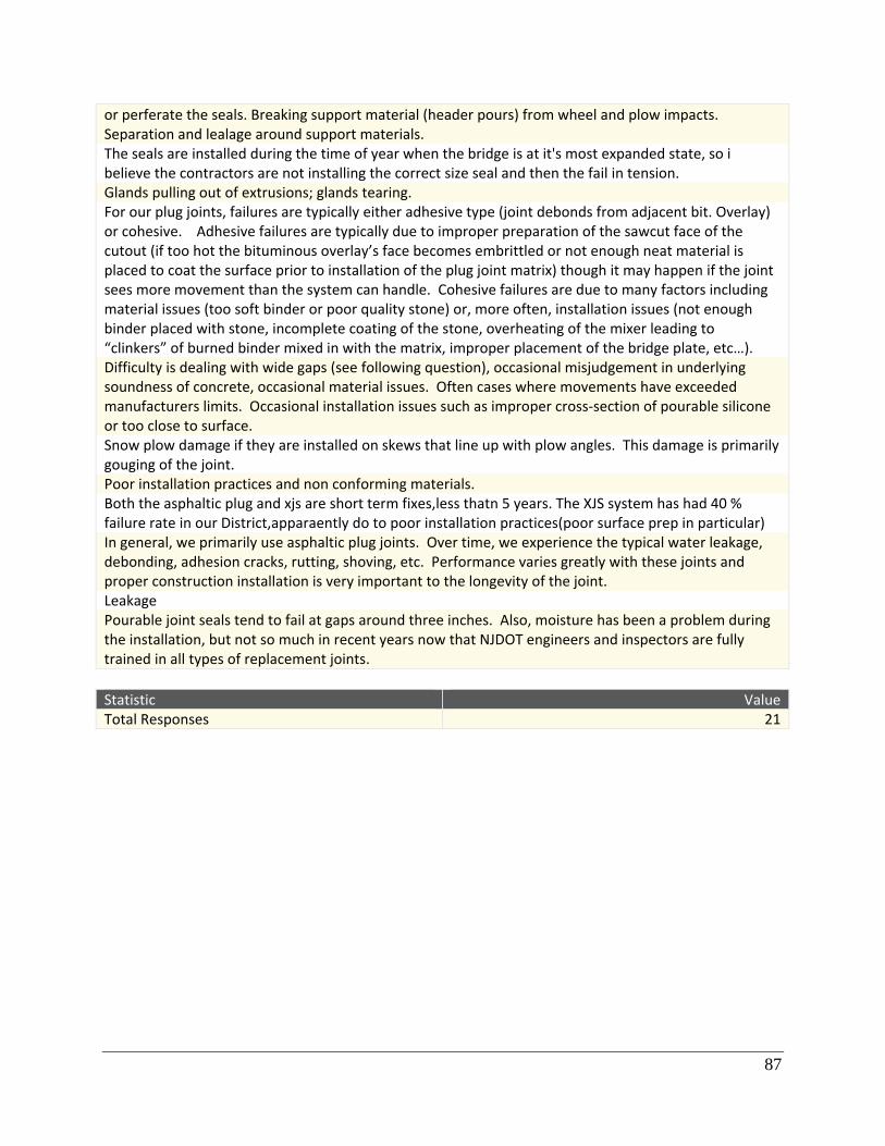
87
or perferate the seals. Breaking support material (header pours) from wheel and plow impacts. Separation and lealage around support materials. The seals are installed during the time of year when the bridge is at it's most expanded state, so i believe the contractors are not installing the correct size seal and then the fail in tension. Glands pulling out of extrusions; glands tearing. For our plug joints, failures are typically either adhesive type (joint debonds from adjacent bit. Overlay) or cohesive. Adhesive failures are typically due to improper preparation of the sawcut face of the cutout (if too hot the bituminous overlay’s face becomes embrittled or not enough neat material is placed to coat the surface prior to installation of the plug joint matrix) though it may happen if the joint sees more movement than the system can handle. Cohesive failures are due to many factors including material issues (too soft binder or poor quality stone) or, more often, installation issues (not enough binder placed with stone, incomplete coating of the stone, overheating of the mixer leading to “clinkers” of burned binder mixed in with the matrix, improper placement of the bridge plate, etc…). Difficulty is dealing with wide gaps (see following question), occasional misjudgement in underlying soundness of concrete, occasional material issues. Often cases where movements have exceeded manufacturers limits. Occasional installation issues such as improper cross‐section of pourable silicone or too close to surface. Snow plow damage if they are installed on skews that line up with plow angles. This damage is primarily gouging of the joint. Poor installation practices and non conforming materials. Both the asphaltic plug and xjs are short term fixes,less thatn 5 years. The XJS system has had 40 % failure rate in our District,apparaently do to poor installation practices(poor surface prep in particular) In general, we primarily use asphaltic plug joints. Over time, we experience the typical water leakage, debonding, adhesion cracks, rutting, shoving, etc. Performance varies greatly with these joints and proper construction installation is very important to the longevity of the joint. Leakage Pourable joint seals tend to fail at gaps around three inches. Also, moisture has been a problem during the installation, but not so much in recent years now that NJDOT engineers and inspectors are fully trained in all types of replacement joints.
Statistic Value Total Responses 21

88
10. If there are systems that you used in the past but no longer do,
please describe them and why you longer use them. Text Response N/A 20" asphaltic plug joint: previously used for up to 1.5" total movement and all locations. Now limited to 3/4" max. movement because the joint has been failing. Compression seal: stopped using because of failure due to leaking. Now designing the seal to be in compression (60% of the seal size). No N/A We still use Dow Corning 902 from time to time but in the volume we used to. It is being phased out possible by the RJ Watson Silicoflex. We have worked with our Bridge Design personnel to reduce the number of places where plug joints are used, but they are still a prevalent joint type. PREFORMED ELASTOMERIC JOINT: THEY SLIDE DOWN OR POP OUT IN SOME CASES. ASPHALTIC PLUG JOINT: USED FOR REHABILITATION APPLICATION FOR ASPHALT OVERLAY ON BRIDGE DECKS. THEY BREAK APART UNDER HEAVY TRAFFIC. We have not eliminated any systems of small movements, but have reduced signficantly the use of compression seals for the fixed end of spans & generally use Slab‐Over‐Backwall and have started using Asphaltic Plugs on some. (Larger movement we eliminated a Bendoflex Design about 15‐20 years ago.) In the past, we have used compression seals. When they start leaking or get damaged, they are being replaced with silicone seals. We find the silicone seal are easier to maintain because they can fixed in localized areas as opposed to compression seals that need to be completely replaced every time a portion of them is damaged or leaks. Both systems last about 5 years before they leak. The foam product under the name of Evazote has been used in the past. What we found was the material would "set" at lower than predicted temperatures, 110 degrees Fahrenhiet which results in the material lossing its elastic properties. The "set" would occur during the summer months and when the bridge contracted during the cold months it would tear away form the sides of the joints. We stopped using the foam when it was reported to us by the manufacturer the material could not be made to have consistant material properties. Armored joints with compression seals were difficult to install properly (concrete voids under the armoring angles) and difficult to replace. Elastomeric headers, especially in asphalt wering surfaces. Too much cracking and no bond at all with the asphalt We no longer use armored headers, because over time they develope pack pust under them which catch the plow blandes and get ripped out. Neoprene compression seals have been discontinued. Not a matter of "if" they fail but when. CTDOT used to use compression seal joints but discontinued use 25 years ago due to the difficulty oin achieving satisfactory installations. NYSDOT typical joint in the 1980's was the Armor Angle and Compression seal (still available on standard detail sheets on internet). We previously used a saw cut filled with sealer on very small bridges. We moved away from them due to pavement distress adjacent to the saw cut. It was felt that rotation of the bridge was often as big a problem as the movement. Number of systems tried in the past. Try to keep systems in use to simple with some track recond of working well. We are trying not to use xjs at all,but using it is better than doing nothing. We have been trying EMSEAL lately

89
We generally do not use compression seal joints in the roadway portion of a bridge due to past problems with the seal pushing out over time. However, this could also be related to lack of maintenance in cleaning out the joints. Compression Joint. Known for Disloging, poping out of place. Asphaltic Plug Joints have had numerous failures across the State
Statistic Value Total Responses 21

90
11. Do you keep detailed records/inspection reports about past
performance? Text Response Yes, we keep a record of each inspections that we perform on our bridges and store the information on PONTIS. Yes. Inspection reports. No Not in the past, but as of last year, we started tracking performance The NHDOT Bureau of Materials and Research may have some expansion joint performance reports if they were involved in the procress. Other than that there is no formal written inspeciton reports of the various joint types. NO detailed reports on joint performance, specific to a product, are not kept in the bridge's inspection file The Departments Inspection program records the condition of all joints, in general, at 24 month intervals. Region Bridge Managers have generally a good idea where their problem bridge joints are. I do not keep any records about about the inspection of the joints. However, there are other division in my office where this is completed. We have only the inspection crews pontis elements. As I mentioned before, I have someone in my office setting up a planned field trip for this fall or winter to review the performance of our pourable and preformed 100% silicone seals. They are not detailed enough. Inspectors only note when it is ovious that the joint is leaking and the inventory of what type of joint and when it was installed on each bridge is not kept up to date. Not as much as we should In the past we didn't keep detailed records of the field conditons of the joints installed by maintenance forces, however we have started to, Maintenance needs are identified so if a joint is leaking, it is so noted. No Every bridge inspected (generally) every two years. We know where joints were replaced via our work reporting mechanism. We attempt to update the physical inventory accordingly, but inventory codes are not sufficiently detailed to capture the various sub‐types (header, seal). However, we can piece together the info. There is no bona‐fide joint‐specific database, but probably should be. No. No In the case of xjs , yes We have element level bridge inspection data since about 2005. Yes, NBI Reports Yes, all bridges repaired are entered into a Work Order System with NJDOT staff performing inspections to evaluate joint performance after the installations.
Statistic Value Total Responses 22

91
12. How does your agency determine widths for small movement
expansion joints? What is the protocol/procedure for determining the
width? Text Response For small movement expansion joints, we use AASHTO LRFD Bridge Specs (always with the most current version). We get widths from calculation of the design thermal movement (LRFD 3.12.2.3‐1). To get the movement, we need to know the following: coefficient of thermal expansion (value varies among timber, steel, and concrete), shear modulus basis (LRFD 14.7.5.2), the length of the bridge (per span), and minimum temperature range (LRFD Table 3.12.2.1‐1). Not everyone interprets the LRFD guidelines the same, this is where our engineering judgement comes in play. Also I tend to round up to the nearest half‐inch (if I am getting 4.25 inch design movement, I assume we will need a system that will accommodate movements up to 4.5 inches). Also we need to keep in mind that the movements goes both ways (longitudinally), hence we need to give sufficient space to allow the beams move towards, or away, from each other. Very hard to explain in writing and there is more to it, but hopefully this makes some sense. Using the total themral movement range including any shrinkage effect and AASHTO load factor Tu for Force Effect due to Uniform Temperature. Yes For the most part they are all standard width (20" +/‐) per manufacturer's recommendations. The NHDOT Bureau of Bridge Design (Angela Hubbard responded to this survey from that group) may have written protocols or procedures. In Bridge Maintenance we will look at the total expected movement of the bridge and rated movement of the joint type ,typically from the manufactorer, and size the joint based on the tempreture expected when the joint is cast and the movement cababilities of the material at that tempreture range. Usually we will come up with a table that lists the joint opening that should be installed based on different tempretures. WIDTH IS BASED ON THE EXPANSION REQUIREMENTS DUE TO TEMPERATURE AND CONTRIBUTARY LENGTH. movement is determined by a range of temperature and expansion length of the bridge; AASHTO design specification is used In general, our agency uses a movement rating of about 1 1/4" of movement per 100 foot of span. Span being the portion of the superstructure that expands and contracts with temperature (i.e. not necessarily the distance from pier to pier, etc.) This is the result of our expected temperature range in Maine to be ‐ 30 degrees to +120 degrees. Theoretically this is the expansion for steel material. It is suggested in AASHTO that this movement is about half for concrete ‐ however ‐ in general the Dept likely treats the superstructures about the same. Between fixed bearings on superstructures, a width is selected to accomodate rotation of the spans ‐ likely around 1/2". We base the size of our joint openings on the manfacturer's recommendations for the allowable moment. We make the openings a small as possible within the allowable expansion and contraction limits for that size opening. We get field measurements of the width of the joint opening and the temperature at the time of these measurements. Then, a spreadsheet that calculates the joint opening is used to list in a table the joint openings for 10 degree increments which is given to the construction team to use. The pourable joint material used usually cannot be installed below 40 degreess, but we try to install the joints when the temperatures are cooler and the opening is as wide as possible. Our procedure is in the process of being revised to minimize tension in the seals. Currently the procedure uses a temperature range of ‐30 to 120 degrees F, distance to fixed bearing, .0000065, +

92
minimum seal size. Design calls out having the seal installed at 68 degrees F. Usually calculate the theoretical movement Currently we use a joint seal calculator developed by our statewide Bridge Maintenance community. It determines the size of the seal required for a particullar bridge at the current joint opening and temperature. Thermal movement computations are performed. Protocol and equations are stipulated in PennDOT design manual. Widths are determined by first determining the anticipated movement of the joint opening due to thermal expansion/contraction forces. The joint opening is then set at a typical 2” open joint at 50 degrees F which is then checked to make sure the opening will not close up at the highest anticipated temperature in CT (110deg F). Our Agency has a chart in the standard sheets (available on the Internet). In Maintenance, we have a calculation spreadsheet that looks at the movement and checks the product‐specific manufacturer's limits. No. Actual width is determined by installer. Follow AASHTO for determing the anticipated range of movement and size the joint accordingly. thermal movement calculation for a single span Widths are calculated based on thermal movements an in accordance with AASHTO. Design Calculations In the NJDOT Bureau of Bridge Maintenance Engineering & Operations, joint widths are all field based and were determined when the bridge was originally constructed. We only replace existing failed joints, typically on bridges over 20 years of age.
Statistic Value Total Responses 22

93
13. Would you be able to provide copies of material specifications
that you currently use? Text Response We currently use AASHTO LRFD Bridge Design Specifications, 6th Edition ‐ 2012. We cannot make any copies of this spec due to copyright laws. yes See Design response Yes If asked, yes we could provide specific information that you might be looking for. YES no, this is nothing I have but may be able to get Yes. Yes Sure Available online at NYSDOT website yes yes Material specs are available in PennDOT Publication 408. see CTDOT Construction rep. as they are the "owners" of the plug joint specification Yes. They are available on the NYSDOT website. Or, I can complile the standard sheets and specifications. Yes. Refer to MassDOT Bridge Manaul for Details (available online) yes Our standard specification are available on our website http://www.dot.ri.gov/engineering/standards/index.asp Yes Yes
Statistic Value Total Responses 22

94
14. Would you be able to provide the protocol and a few examples of
design calculations for determining the joint width? Text Response Unfortunately, no. yes See design response no Possible, agin in Bridge Maintenance I don't know that we have any protocols per say. THE DESIGN CALCULATIONS ARE BASED ON THE COEFFICIENT OF THERMAL EXPANSION OF STEAL OR CONCRETE AND THE CONTRIBUTARY LENGTH. same as above Yes. Yes Yes We have a Excel spread sheet that we use. Not until new procedure is reviewed and approved. yes yes The design procedures are outlined in PennDOT Design Manual Part 4 ‐ Structures. see CTDOT Bridge Design. Yes. I can share my Regional spreadsheet, but I can't endorse specific product manufacturers. Can provide the standard detail sheet included in projects. Yes yes Not Sure. Design and Engineering section willl have such documents No
Statistic Value Total Responses 21

95
A.4Follow‐upInterviewQuestions
Questions asked and detail required will be very dependent on amount of information given in initial survey. General Does your state have standard detail drawings of the joint types used by the DOT?
Follow-up on Joint Types used according to survey response as opposed to what the State DOT Manual says. Do they match? Why or why not?
General follow-up on any unclear answers. What is the approval process for joint systems or pieces of systems? Does your DOT use PONTIS?
Design Related
Is AASHTO LRFD Manual main source for determining movement of joints?
Is AASHTO LRFD Manual main source for selecting joint type?
Does the DOT have any joints that are specifically avoided? Why? Does the DOT have any joints that are being phased out? Why?
Are seals allowed to go into tension? If so, is this causing problems? Maintenance Related Is there a Bridge Maintenance Manual separate from the Design Manual for your state?
(Try to obtain copy) Have you heard of or use the AASHTO Guide Manual for Bridge Element Inspections?
Confirm problems with joint types used and average lifespans given in survey.
Ask for personal opinion as to whether joints are behaving as expected under wear and tear.
If they are not, what is altering their performance (poor installation, unexpected conditions…)

96
How often are bridge joints inspected/cleaned?
When sizing replacement joints, how is movement determined? (AASHTO? Bridge plans? Seal manufacturer?) How often is over compression or compression set an issue with seals. How is it being fixed? Are detailed inspection reports of the joints kept? And if so are they summarized/maintained in a database? Does your state use any unique methods for maintenance that are separate from manufacturer or written specifications? Does your state offer any special training or information regarding joints?

97
A.5ListofManufacturersandAssociatedJoints
Company* Representative Email Phone Joints
C.S. Behler Tom Casarsa [email protected] 7169121262 PS Crafco Job Davis [email protected] 603‐3878430 APJ Dow Corning 989‐496‐7875 PS D.S. Brown Linnea Barone [email protected] 732‐262‐4885 CS, PS, CCF,
SS Dynamic Surface Applications
Jamie Freudenberger
jamief@dsa‐ltd.com 570‐546‐6041 APJ
EMSEAL Irene Friedman [email protected] 508‐836‐0280 OCF Polyset Tom Meacham [email protected] 518‐664‐6000 CCF R.J. Watson Joe Becker [email protected] 585‐414‐0564 PFS, CCF Watson Bowman Acme
Casey Woodlock [email protected] 716‐817‐5459 APJ, CS, PS, PFS, CCF, SS
*This list includes manufactures that were common among the surveyed NEBPP DOTs. This list is not all inclusive and other manufacturers may be available.


