PAPER www.rsc.org/materials | Journal of Materials Chemistry
Publ
ishe
d on
17
Mar
ch 2
008.
Dow
nloa
ded
by U
nive
rsite
it U
trec
ht o
n 08
/09/
2013
17:
47:2
4.
View Article Online / Journal Homepage / Table of Contents for this issue
Silica-free syntheses of hierarchically ordered macroporous polymer andcarbon monoliths with controllable mesoporosity†
Zhiyong Wang, Elizabeth R. Kiesel and Andreas Stein*
Received 18th December 2007, Accepted 27th February 2008
First published as an Advance Article on the web 17th March 2008
DOI: 10.1039/b719489g
Hierarchically ordered macroporous polymer and carbon monoliths with walls containing
face-centered cubic or 2D-hexagonal mesopores were synthesized via a facile dual-templating technique
using poly(methyl methacrylate) (PMMA) colloidal crystals and amphiphilic triblock copolymer
surfactants as templates. A nanocasting step using a silica mold was not required. The as-synthesized
nanoporous structures contain both ordered macropores and mesopores, originating from the colloidal
crystal and surfactants, respectively. The mesostructures could be conveniently controlled by
tuning the concentration of the copolymer surfactant. Starting from the PMMA template, only four
major processing stages (precursor infiltration, solvent removal, thermal curing and carbonization)
were involved to prepare the bimodal porous carbon materials. A two-step thermal curing method was
utilized to improve the robustness of the products. On the basis of nanoindentation measurements, the
carbon products were mechanically more stable than hierarchically porous carbon monoliths
synthesized by nanocasting, and the product with the cubic mesopore structure was even more stable
than 3D-ordered macroporous carbon lacking any templated mesopores in the wall skeleton.
Compared with conventional nanocasting strategies, the current method avoids the use of hazardous
hydrofluoric acid that is required to remove a silica template, and therefore the synthetic procedure is
more environmentally benign.
Introduction
Among the variety of nanostructured materials, carbon with
designed porosity is a promising candidate in applications as
varied as gas separation, water purification, chromatography,
catalysis, hydrogen storage, controlled drug release and
electrodes for electrochemical devices.1 All of these applications
can benefit from better control over the pore structure and
morphology of synthetic carbon materials. In this paper we
report straight-forward and reliable syntheses of nanoporous
carbon and polymer materials with well-controlled morpho-
logies at multiple length scales.
Porous carbons with random mesopores have been known for
a long time, for example in the form of activated carbon.
However, for better access to the interior of the carbonaceous
materials and for applications requiring size-selectivity, a more
ordered mesoporous structure is desirable. Since the pioneering
work of Ryoo et al.,2 interest in ordered mesoporous carbon
has been escalating. Initially, ordered mesoporous carbon was
synthesized by a nanocasting strategy with ordered mesoporous
silica as a hard template and organic compounds, such as
sucrose2 and acetonitrile,3 as carbon precursors. In addition,
a modified method was invented by Hyeon and co-workers in
which block copolymer surfactants were carbonized directly
within mesoporous silica frameworks followed by silica
removal.4 Mesoporous carbon materials with space group
Department of Chemistry, University of Minnesota, Minneapolis, MN55455, USA. E-mail: [email protected]
† Electronic supplementary information (ESI) available: Fig. S1, S2 andTable S1. See DOI: 10.1039/b719489g
2194 | J. Mater. Chem., 2008, 18, 2194–2200
symmetries p6mm,5,6 I41/a,2,7 and Ia3d8 have been prepared by
nanocasting methods. The available geometries accessible by
nanocasting are limited to templates (usually silica) with inter-
connected mesoporous channels capable of generating robust,
negative carbon replicas.5 Furthermore, all of the above methods
require either hydrofluoric acid or sodium hydroxide solutions
for silica removal, thus complicating the synthesis.
In order to simplify the production of ordered mesoporous
carbon and to circumvent the use of hazardous chemicals, direct
synthesis techniques were developed. Dai and co-workers first
reported the preparation of hexagonally ordered mesoporous
carbon using resorcinol monomers and a self-assembled copoly-
mer polystyrene-block-poly(4-vinylpyridine) as a mesopore-
directing agent.9 The carbonized product has large mesopores
due to the high molecular weight of the copolymer. Later,
Nishiyama et al. synthesized hexagonally ordered mesoporous
carbon thin films using the inexpensive triblock copolymer,
Pluronic F127, resorcinol-formaldehyde and triethyl ortho-
acetate.10 Recently, a more versatile strategy was reported by
Zhao and co-workers, exploiting the cooperative assembly
between resols and block copolymers to produce ordered
mesoporous carbons with p6mm, Ia3d, Im3m and Fm3m space
groups.11,12 Most of these methods generated carbon samples
as powders or thin films, and there have been very few reports
of direct syntheses of monolithic carbon with ordered meso-
porous structure up to now.13 Moreover, mesoporous carbon
particles prepared by these methods have relatively large external
dimensions (typically over one micrometre), which results in
relatively long diffusion path lengths for guest molecules,
limiting mass-transport.
This journal is ª The Royal Society of Chemistry 2008
Publ
ishe
d on
17
Mar
ch 2
008.
Dow
nloa
ded
by U
nive
rsite
it U
trec
ht o
n 08
/09/
2013
17:
47:2
4.
View Article Online
One solution to the diffusion limitation is to design a hierarchi-
cally ordered porous structure containing both well-defined
macropores and mesopores. This structure can provide excellent
mass transport through macropores and a large surface area
from mesopores within macropore walls.14 Macropores may be
generated, for example, by colloidal crystal templating to form
a three-dimensionally ordered macroporous (3DOM) struc-
ture.15 Our previous studies have shown that 3DOM carbon,
as an anode for lithium ion batteries, has structural advantages
that would permit high lithiation/delithiation rates.16 Chai
et al. reported that the introduction of secondary mesopores
into a 3DOM carbon skeleton by templating with secondary
silica nanoparticles led to an improved electrochemical activity
when the biporous carbon-product was employed as a catalyst
support in a direct-methanol-fuel-cell.14 Our group synthesized
a hierarchically ordered mesoporous carbon monolith via
nanocasting from a biporous silica template.17 To simplify such
syntheses, two new methods were developed recently. Zhao
and co-workers prepared hierarchically porous carbons from
a dual template approach using silica colloidal crystals and
triblock copolymers as the templates.18 At the same time, our
group reported the synthesis of three-dimensionally ordered
macro-/mesoporous (3DOM/m) carbon monoliths using a
poly(methyl methacrylate) (PMMA) colloidal crystal template
and a triconstituent precursor.19 The as-synthesized carbon
monoliths appeared metallic-yellow opalescent under room light
and had easily controllable dimensions dictated by the PMMA
template. However, both methods required hydrofluoric acid
to remove the silica mold, raising environmental concerns.
Recently a silica-free, direct synthesis route of producing ordered
mesoporous carbon nanocubes was communicated by our
group.20
Here, we report novel direct syntheses of hierarchically porous
phenol-formaldehyde-based (PF-based) polymer and carbon
monoliths with both ordered macropores and mesopores
(3DOM/m PF and 3DOM/m C), controllable mesopore architec-
tures and centimetre-sized external dimensions. The overall
strategy is illustrated in Scheme 1. Only four key stages are
involved in the fabrication of the 3DOM/m products: (1) infiltra-
tion of a solution containing the carbon precursor and a surfac-
tant into a colloidal crystal template, (2) thermal curing, (3)
solvent removal, (4) template removal and/or carbonization.
After the fourth stage, biporous ordered polymer or carbon
Scheme 1 Formation of 3DOM/m PF and 3DOM/m C monoliths. The
syntheses involve four basic steps: (1) infiltration of a precursor solution
containing resol solution, copolymer surfactant and hydrochloric acid
into a PMMA colloidal crystal template, (2) thermal cross-linking of
the resol with surfactant micelles within the void space of the colloidal
crystal, (3) solvent removal under dynamic vacuum, (4) template removal
and carbonization of the composite under an inert atmosphere. A
phenol-formaldehyde-based polymer is produced if the 4th step is carried
out at a lower temperature that eliminates PMMA but does not
carbonize the product.
This journal is ª The Royal Society of Chemistry 2008
monoliths are generated as the final products, depending on
the heating temperature. To the best of our knowledge, this is
the first report of direct syntheses of hierarchically ordered
porous carbon monoliths that completely eliminate any silica
intermediate and the use of hydrofluoric acid. As a result, these
syntheses are safer, easier, cheaper and more environmentally
benign than nanocasting methods employing silica templates.
Experimental
Chemicals
Chemicals used in this experiment were obtained from the
following sources: 2,20-azobis(2-methyl propionamidine)
dihydrochloride initiator (AMPD, 97%), and methyl metha-
crylate monomer (MMA, 99%) were purchased from Aldrich.
Phenol (ACS reagent) and formaldehyde (37% aq. solution)
were from Fisher Scientific. Hydrochloric acid (37%) and sodium
hydroxide were from Mallinckrodt Chemicals. Pluronic� F127
(a difunctional non-ionic ethylene oxide–propylene oxide block
copolymer surfactant, EO97PO69EO97, terminating in primary
hydroxyl groups, average molecular weight 12 600) was received
as a gift from BASF. All chemicals were used without further
purification.
Synthesis of 3DOM/m-c and 3DOM/m-h monoliths
The PMMA colloidal crystal template was prepared by
emulsifier-free emulsion polymerization of MMA at 70 �C with
AMPD as an initiator, as described elsewhere.21 The resulting
PMMA sphere suspension was transferred to a covered glass
crystallization dish and stored for several weeks at room
temperature without agitation. As PMMA spheres sedimented
on the bottom of the container, the water was allowed to
evaporate forming opalescent colloidal crystal pieces. 3DOM/m
PF and 3DOM/m C monoliths with two different mesoporous
structures were prepared in a direct dual-templating method. A
50 wt% phenol-formaldehyde (PF) resol solution in ethanol
(pH �7) was first synthesized according to an established
method.12 In a typical synthesis, 2.0 g PF sol was mixed with
1.0 g of 0.2 M HCl(aq) in a glass vial. Next, 0.5 g (for cubic
3DOM/m-c) or 1.0 g (for hexagonal 3DOM/m-h) of F127 was
added to this clear mixture and stirred for at least 6 h at room
temperature to form a homogeneous, yellow solution. PMMA
monoliths were infiltrated with the above precursor solution
inside a capped container. Care was taken that the solution level
was not above the PMMA pieces. After excess solution was
wiped off the monoliths, these pieces were placed in a vacuum
oven for 3–6 h at 50–60 �C to remove the solvent at reduced
pressure (< 0.5 mmHg). Cross-linking was achieved by thermally
curing the precursor-infiltrated monoliths, first at 100 �C for 24 h
in capped plastic bottles and then at 140 �C for 24 h within
loosely covered Petri dishes. Phenolic resin monoliths were
obtained after heating at 450 �C for 3 h with a heating rate of
1 �C min�1 under flowing N2 (1 L min�1). These samples were
denoted as 3DOM/m-cPF (cubic phase) and 3DOM/m-hPF
(hexagonal phase). Carbon monoliths were generated by carbo-
nizing the thermally-cured phenolic resin–PMMA composite
under flowing N2 (1 L min�1) at 450 �C for 3 h and then at
900 �C for another 2 h with a heating rate of 1 �C min�1. These
J. Mater. Chem., 2008, 18, 2194–2200 | 2195

Publ
ishe
d on
17
Mar
ch 2
008.
Dow
nloa
ded
by U
nive
rsite
it U
trec
ht o
n 08
/09/
2013
17:
47:2
4.
View Article Online
samples were denoted as 3DOM/m-cC and 3DOM/m-hC,
respectively.
Characterization
C, H, O elemental analyses (EA) of the samples were performed
by Atlantic Microlab Inc. of Norcross, GA. Scanning electron
microscopy (SEM) images were obtained with a JEOL 6700
scanning electron microscope at an accelerating voltage of
5 kV. Samples were ground to a powder and then mounted on
an aluminium stub with conductive carbon tape. Transmission
electron microscopy (TEM) was conducted on a JEOL model
JEM-1210 electron microscope operated at 120 kV. All samples
were crushed to a powder and sonicated in ethanol for 1 h before
TEM analysis. They were drop-dried from acetone onto TEM
grids. Small-angle X-ray scattering (SAXS) data were acquired
on a Rigaku RU-200BVH 2D SAXS instrument using
a 12 kW-rotating anode with a Cu source and a Siemens
Hi-Star multi-wire area detector. The sample-to-detector
distance was 108 cm, exposure time 10 minutes for each sample
and the step interval 0.008� 2q. All samples were ground into fine
powders before running tests. Nitrogen-sorption measurements
were performed on a Quantachrome Autosorb-1 Automated
Gas Sorption System. Samples were degassed at 0.003 mmHg
for at least 12 h at 200 �C. Specific surface areas were calculated
by the Brunauer–Emmett–Teller (BET) method, and pore sizes
and volumes were estimated from pore size distribution curves
from the desorption branches of the isotherms using the
Barrett–Joyner–Halenda (BJH) method. Pore volumes were
taken at the P/P0 ¼ 0.995 single point. Depth-sensing indenta-
tion (DSI) experiments were performed using an instrumented
indenter (Nano Indenter XP, MTS Systems Corporation) with
a diamond Berkovich indentation tip. The maximum load for
each sample was 15–16 mN. Multiple load-unload cycles were
conducted for each sample to examine the reproducibility. To
evaluate the influence of mesoporosity on the strength of
monoliths, a 3DOM carbon monolith derived from a resorcinol-
formaldehyde precursor (3DOM RFC) without mesoporosity
inside macropore walls was prepared according to our previously
developed method.16
Results and discussion
Precursor conditions
As a starting point, a resol precursor composition used in
previous reports of mesoporous carbon films was employed.12
To explore the mesophases attainable in the confinement of
a PMMA colloidal crystal, the surfactant concentration was
varied. On the basis of the analyses described below, hierarchi-
cally ordered polymer and carbon monoliths with an fcc meso-
structure (3DOM/m-c) were synthesized at a low surfactant
concentration in the precursor solution with molar compositions
of 1.0 phenol, 2.0 formaldehyde, 6.1–8.6 � 10�3 F127, 3.1 � 10�2
HCl, 8.5 H2O, 3.3 EtOH. A mesostructure phase transformation
from cubic to 2D-hexagonal was observed when the concentra-
tion of F127 was increased in the precursor solution to molar
compositions of 1.0 phenol, 2.0 formaldehyde, 1.2–1.8 � 10�2
F127, 3.1 � 10�2 HCl, 8.5 H2O, 3.3 EtOH for 3DOM/m-h.
Here the presence of hydrochloric acid was essential for the
2196 | J. Mater. Chem., 2008, 18, 2194–2200
dissolution of F127, probably due to the enhancement of the
interactions between the protic solvents and the oxyethylene
segments in F127. To produce highly ordered macro- and
mesoporous frameworks, it was also vital to remove solvents
(especially ethanol, which is known to retard the formation of
an ordered mesostructure)22 before the thermal curing step. A
material with completely disordered mesopores and macropores
was obtained without this solvent-removal process.
Thermal curing
A two-step thermal curing procedure was employed. The first
step was conducted at 100 �C for 24 h within a capped plastic
container to solidify and pre-cross-link the resol. This tempera-
ture was selected for the following reasons. At temperatures
lower than 100 �C, cross-linking of resol is too slow; however,
excessively high temperatures destroy the surfactant micelles
and lead to macroscopic phase separation between F127 and
the resol. Moreover, temperatures higher than the glass transi-
tion temperature deform the PMMA colloidal crystal (Tg of
PMMA is ca. 105 �C) because the composite is insufficiently
hardened at the early processing stage. Heating in a closed
container is very important during this first step since a sufficient
amount of HCl is required to achieve a high-degree of cross-
linking, and HCl would be slowly lost in an open container.
After this polymerization step, the monolith was orange. The
extent of cross-linking of the phenolic resin is related to its color:
the higher the cross-linking level, the darker the color. Poorly
cross-linked phenolic resin normally gives a pale-yellow color.
The second step involves curing the composite at 140 �C. This
is intended to further harden the resin and avoid corruption of
the mesostructure during the decomposition of the surfactant
and the subsequent carbonization step. This temperature corres-
ponds to an empirically established optimum. Heating tempera-
tures lower than 140 �C did not influence the cross-linking and
mesopore order significantly (compared with curing at 100 �C);
temperatures higher than 140 �C produced samples with closed
mesopores that were not accessible in nitrogen sorption experi-
ments. After this step, the monoliths were dark-brown and
appeared opalescent. It is worth noting that the periodic
structure of the PMMA colloidal crystal was maintained even
though the temperature was far beyond the Tg of PMMA at
this second step. The PMMA spheres were restrained within
a hard phenolic resin framework due to the pre-solidification
from the first step.
Template removal and carbonization
After the two-step curing, the PMMA–phenolic resin composite
was heated under flowing nitrogen at 450 �C to decompose the
copolymer surfactant and the PMMA template to yield
3DOM/m phenolic resin monoliths. When the composite was
heated up to 900 �C, the polymer was converted to a glassy
carbon phase. As-synthesized 3DOM/m monoliths had typical
dimensions of about 0.6 � 0.5 � 0.3 cm3 (Fig. 1). 3DOM/
m-cPF and 3DOM/m-hPF monoliths were dark brown whereas
3DOM/m-cC and 3DOM/m-hC monoliths were black. Cross-
sections of these monolithic samples appeared opalescent as
a result of the periodic structure with repeat lengths on the order
This journal is ª The Royal Society of Chemistry 2008

Table 1 Elemental analysis results of phenolic resin and carbon mono-liths
SampleElement content/wt %
FormulaC H O Total
3DOM/m-cPF 86.09 3.98 8.05 98.12 C14.3H7.8O3DOM/m-cC 94.79 0.22 2.34 97.35 C54.1H1.5O3DOM/m-hPF 86.98 3.96 6.92 97.86 C16.7H9.1O3DOM/m-hC 94.37 0.21 2.38 96.96 C52.7H1.4O
Fig. 1 Photograph of 3DOM/m monoliths.
Publ
ishe
d on
17
Mar
ch 2
008.
Dow
nloa
ded
by U
nive
rsite
it U
trec
ht o
n 08
/09/
2013
17:
47:2
4.
View Article Online
of the wavelength of visible light. Phenolic resin samples
(3DOM/m-c and 3DOM/m-h) contained hydrogen and oxygen
in high concentrations (Table 1). After carbonization at 900�C, both the oxygen and hydrogen contents decreased. The total
percentages of C, H and O analyzed were slightly less than
100%, which could be due to some inorganic residues from the
reactants.
Structural analysis
Scanning electron microscopy images revealed that all carbo-
nized monoliths had an ordered macropore structure (Fig. 2).
On the basis of SEM images, the PMMA spheres used to template
3DOM/m C monoliths had diameters of 416 � 11 nm.19
After removal of the PMMA template by heat treatment at
Fig. 2 SEM images of carbon monoliths: 3DOM/m-cPF (A), 3DOM/
m-cC (B), 3DOM/m-hPF (C) and 3DOM/m-hC (D).
This journal is ª The Royal Society of Chemistry 2008
450 �C, a well-interconnected framework composed of phenolic
resin was formed (Fig. 2A and 2C). The macropore diameters
of 3DOM/m-cPF and 3DOM/m-hPF were 394 � 7 and 404 �11 nm respectively (Table 2), indicating relatively little shrinkage
after removal of the PMMA spheres (3–5%). After carbonization
at 900 �C under nitrogen, macropore diameters further decreased
to 342 � 6 and 348 � 7 nm for 3DOM/m-cC and 3DOM/m-hC,
respectively. At this stage, the shrinkage of the 3DOM framework
with respect to PMMA was significant (16–18%). The large
shrinkage might be due to the loss of low-molecular-weight
components during pyrolysis at high temperatures. Although
the amount of shrinkage of 3DOM/m-cC and 3DOM/m-hC was
greater than for a 3DOM/m C monolith prepared by a triconsti-
tuent method using the same PMMA template (12%),19 macro-
pore window sizes of these samples were larger (ca. 150 nm for
3DOM/m-cC vs. 130 nm for 3DOM/m C synthesized via the
triconstituent method). The big windows could be the result of
high temperature annealing of PMMA during the second curing
step which coarsens the necks between adjacent PMMA spheres.
The wider windows can facilitate mass transport if 3DOM/m C is
used for applications such as catalysis and energy storage.
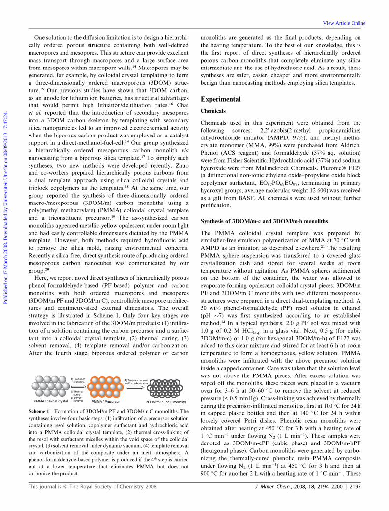
The interior structure of the 3DOM/m-c samples was analyzed
by TEM (Fig. 3 and ESI†, Fig. S1). Regularly patterned, sphe-
rical mesopores were observed across the entire polymer and
carbon samples. Mesopores were well ordered within octahedral
and tetrahedral centers of the 3DOM skeleton (i.e., centers
corresponding to octahedral and tetrahedral holes in the original
colloidal crystal template). The mesostructure became slightly
less ordered near the macropore wall surface. These observations
suggest that interactions between surfactant molecules and the
PMMA surface, as well as confinement effects, influenced the
alignment of F127 micelles. Based on the pore geometries and
pore spacings apparent in the TEM images along the [100],
[110] and [111] viewing directions, a cubic structure correspond-
ing to the Fm3m space group is proposed for mesopores in the
3DOM/m-c samples (see also ESI†, Fig. S2). The orientation
of the mesostructure dovetails with that of the 3DOM structure,
as we also observed in mesoporous carbon nanoparticles.20
TEM images of 3DOM/m-h samples revealed significantly
different mesostructures. 2D-hexagonally ordered mesopores
were observed along the [100] axis of the 3DOM framework
(Fig. 3 and ESI†, Fig. S1). Within small domains, the orientation
of cylindrical mesopores correlated with that in adjacent octa-
hedral centers, but such correlations did not extend throughout
the complete sample. In addition, some distortion was observed
around the core region of mesopore bundles. When viewing the
sample through the [110] direction of the 3DOM structure, it was
noticeable that mesoporous channels followed the curvature of
macropore wall surface. This is additional indirect evidence
that the self-assembly of F127 micelles was influenced by the
PMMA sphere surfaces. A similar phenomenon was reported
in our previous work on 3DOM/m silica monoliths using
Pluronic P123 as mesopore-generating agent.23
Small-angle X-ray scattering was used to confirm the mesopore
symmetries of the 3DOM/m monoliths (Fig. 4). For 3DOM/
m-cPF, a strong scattering peak at 0.80� 2q can be assigned to
the reflection from (200) planes in the cubic mesopore structure
(Fig. 4A). The peak is relatively broad, consistent with small
ordering domains in the mesostructure and in agreement with
J. Mater. Chem., 2008, 18, 2194–2200 | 2197
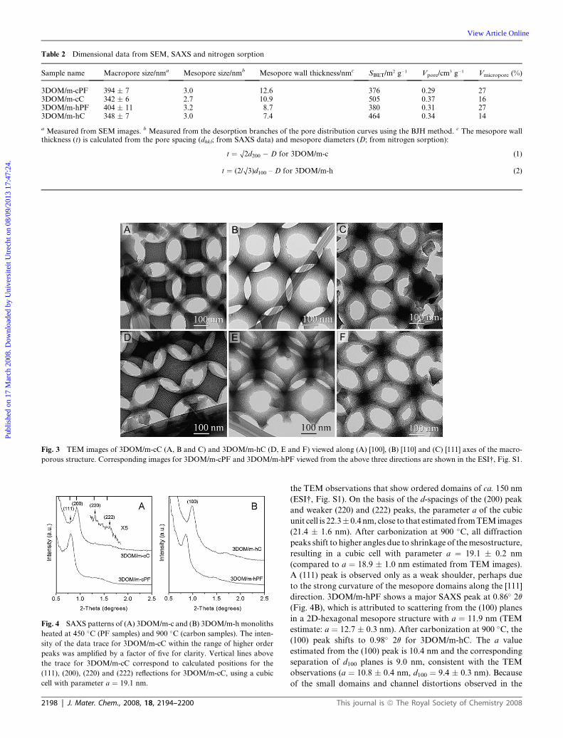
Table 2 Dimensional data from SEM, SAXS and nitrogen sorption
Sample name Macropore size/nma Mesopore size/nmb Mesopore wall thickness/nmc SBET/m2 g�1 Vpore/cm3 g�1 Vmicropore (%)
3DOM/m-cPF 394 � 7 3.0 12.6 376 0.29 273DOM/m-cC 342 � 6 2.7 10.9 505 0.37 163DOM/m-hPF 404 � 11 3.2 8.7 380 0.31 273DOM/m-hC 348 � 7 3.0 7.4 464 0.34 14
a Measured from SEM images. b Measured from the desorption branches of the pore distribution curves using the BJH method. c The mesopore wallthickness (t) is calculated from the pore spacing (dhkl; from SAXS data) and mesopore diameters (D; from nitrogen sorption):
t ¼ O2d200 � D for 3DOM/m-c (1)
t ¼ (2/O3)d100 – D for 3DOM/m-h (2)
Fig. 3 TEM images of 3DOM/m-cC (A, B and C) and 3DOM/m-hC (D, E and F) viewed along (A) [100], (B) [110] and (C) [111] axes of the macro-
porous structure. Corresponding images for 3DOM/m-cPF and 3DOM/m-hPF viewed from the above three directions are shown in the ESI†, Fig. S1.
Fig. 4 SAXS patterns of (A) 3DOM/m-c and (B) 3DOM/m-h monoliths
heated at 450 �C (PF samples) and 900 �C (carbon samples). The inten-
sity of the data trace for 3DOM/m-cC within the range of higher order
peaks was amplified by a factor of five for clarity. Vertical lines above
the trace for 3DOM/m-cC correspond to calculated positions for the
(111), (200), (220) and (222) reflections for 3DOM/m-cC, using a cubic
cell with parameter a ¼ 19.1 nm.
2198 | J. Mater. Chem., 2008, 18, 2194–2200
Publ
ishe
d on
17
Mar
ch 2
008.
Dow
nloa
ded
by U
nive
rsite
it U
trec
ht o
n 08
/09/
2013
17:
47:2
4.
View Article Online
the TEM observations that show ordered domains of ca. 150 nm
(ESI†, Fig. S1). On the basis of the d-spacings of the (200) peak
and weaker (220) and (222) peaks, the parameter a of the cubic
unit cell is 22.3� 0.4 nm, close to that estimated from TEM images
(21.4 � 1.6 nm). After carbonization at 900 �C, all diffraction
peaks shift to higher angles due to shrinkage of the mesostructure,
resulting in a cubic cell with parameter a ¼ 19.1 � 0.2 nm
(compared to a ¼ 18.9 � 1.0 nm estimated from TEM images).
A (111) peak is observed only as a weak shoulder, perhaps due
to the strong curvature of the mesopore domains along the [111]
direction. 3DOM/m-hPF shows a major SAXS peak at 0.86� 2q
(Fig. 4B), which is attributed to scattering from the (100) planes
in a 2D-hexagonal mesopore structure with a ¼ 11.9 nm (TEM
estimate: a ¼ 12.7 � 0.3 nm). After carbonization at 900 �C, the
(100) peak shifts to 0.98� 2q for 3DOM/m-hC. The a value
estimated from the (100) peak is 10.4 nm and the corresponding
separation of d100 planes is 9.0 nm, consistent with the TEM
observations (a ¼ 10.8 � 0.4 nm, d100 ¼ 9.4 � 0.3 nm). Because
of the small domains and channel distortions observed in the
This journal is ª The Royal Society of Chemistry 2008

Fig. 5 Results from nitrogen sorption experiments. (A) and (C) are
isotherms while (B) and (D) are pore size distribution curves calculated
by BJH method from the desorption branches. The symbols (hollow circle,
solid circle, hollow triangle and solid triangle) represent data for 3DOM/
m-cPF, 3DOM/m-cC, 3DOM/m-hPF and 3DOM/m-hC, respectively.
Fig. 6 (A) Indentation load–displacement (P–h) responses and (B) plots
of the indentation contact response in pressure-volume (p–V) space for
indentations made for a maximum load of 15–16 mN. Data traces in
red, orange, blue and green colors correspond to 3DOM/m-cC,
3DOM/m-hC, 3DOM RFC and 3DOM/m-nC, respectively. Here
3DOM/m-nC denotes the 3DOM/m carbon monolith prepared by our
previously reported nanocasting method. Data for 3DOM RFC and
3DOM/m-nC were both adopted from ref. 17.
Publ
ishe
d on
17
Mar
ch 2
008.
Dow
nloa
ded
by U
nive
rsite
it U
trec
ht o
n 08
/09/
2013
17:
47:2
4.
View Article Online
TEM images, the SAXS patterns for the 3DOM/m-hPF and
3DOM/m-hC samples only approximate those for a well-ordered
2D hexagonal mesostructure. Therefore, the low intensity peaks
between 1.3 and 2.0� 2q were not indexed.
Nitrogen sorption experiments were performed to evaluate the
overall porosity of the polymer and carbon samples (Fig. 5). All
these samples showed type-IV isotherms with narrow hysteresis
loops in the P/P0 range of 0.3–0.8, consistent with the meso-
porous nature of the skeletal walls (Fig. 5A and 5C).24 However,
isotherm shapes are different for the polymer and carbon
samples. The hysteresis loops of 3DOM/m-cPF and 3DOM/
m-hPF do not close, even at very low P/P0 values. This behavior
may be related to the ability of the polymers to swell in liquid
nitrogen during the adsorption measurements.25 This explana-
tion is supported by the observation that the polymer samples
contained almost twice as much microporosity as the carbon
counterparts (Table 2). 3DOM/m-cPF and 3DOM/m-hPF had
BET surface areas of 376 and 380 m2 g�1, respectively, and these
values increased to 505 and 464 m2 g�1 after carbonization at
900 �C under flowing nitrogen. All the 3DOM/m-c and
3DOM/m-h samples exhibited very narrow pore size distribu-
tions with mesopore diameters of ca. 3 nm, and this value
decreased slightly after the transformation from polymer to
carbon (Table 2). The pore size distribution curves show a steep
rise at pore diameters below 2 nm, which indicates that signifi-
cant fractions of micropores are present (Fig. 5B and 5D). The
total pore volumes for 3DOM/m-cC and 3DOM/m-hC are
comparable (0.37 and 0.34 cm3 g�1), and these values are smaller
than for 3DOM/m carbon monoliths we prepared previously via
nanocasting or from triconstituent precursors.17,19
Mechanical properties
The 3DOM/m-cC and 3DOM/m-hC samples were found to be
much stronger than other 3DOM/m carbon monoliths with
hierarchical porosity we reported before,17,19 and they can all
This journal is ª The Royal Society of Chemistry 2008
be handled easily without breakage. To further evaluate their
mechanical strength, depth-sensing indentation (DSI) was
employed. A load was applied on monoliths between 0 and
16 mN while displacements of the indenter tip were recorded
in multi-cycle tests (Fig. 6A). At the same load, the displace-
ments of 3DOM/m-cC with cubic mesopores were smaller than
those reported for 3DOM RF carbon without designed
mesoporosity (3DOM RFC).17 In spite of the hierarchical pore
structure, the dual-templated product displayed a higher
resistance toward deformation than 3DOM RFC prepared only
with a colloidal crystal template. This behavior contrasts with
that of 3DOM/m-hC with 2D hexagonal mesopores. Although
for this sample the reproducibility of the load displacement curves
in multiple test cycles was poor, all curves indicated that 3DOM/
m-hC was less rigid than the other two samples. All three samples
were significantly stronger than 3DOM/m-nC prepared via
a nanocasting route.22 It is difficult to obtain modulus and
hardness values directly from the standard load-displacement
traces in Fig. 6A due to the non-elastic and non-volume-
conserving responses of porous materials.26,27 However, a
material parameter could be derived from indentation pressure
vs. indentation volume plots to compare the ‘‘strengths’’ of these
samples. Fig. 6B shows pressure–volume (p–V) traces calculated
from the typical P–h traces according to a published method.26
Based on these plots, the strengths of the monoliths followed
the sequence 3DOM/m-cC > 3DOM RFC > 3DOM/m-hC >
3DOM/m-nC. It is interesting that the more porous 3DOM/
m-cC monolith was stronger than the 3DOM RFC monolith
without secondary mesopores in the walls. This could be a
function of multiple parameters, including differences in the
secondary curing temperature, precursor type and catalyst used
during the syntheses of these two samples. The 3DOM/m-hC
monolith was not as strong as 3DOM/m-cC since the former
was built up with much thinner mesopore walls (Table 2). In
addition, the macroscopic strength of 3DOM/m monoliths could
also relate to their internal nanostructures. 3DOM/m-cC was
composed of a three-dimensional, interconnected mesoporous
framework while 3DOM/m-hC had a two-dimensional, cylin-
drical mesopore structure. Therefore, the internal structure of
3DOM/m-hC was more deformable and consequently it was
not as strong as that of 3DOM RFC.
J. Mater. Chem., 2008, 18, 2194–2200 | 2199
Publ
ishe
d on
17
Mar
ch 2
008.
Dow
nloa
ded
by U
nive
rsite
it U
trec
ht o
n 08
/09/
2013
17:
47:2
4.
View Article Online
Conclusions
Hierarchical polymer and carbon monoliths with ordered macro-
and mesopores were synthesized via a facile dual-templating
technique involving colloidal crystal and block copolymer
templates. The mesostructure could be easily controlled by tuning
the concentration of the block copolymer. A two-step thermal
curing strategy was adopted to achieve a highly cross-linked
mesostructure composed of phenolic resin and block copolymer.
This technique ensured the formation of robust mesopore walls
containing phenolic resin that survived during the decomposition
of the block copolymer template. The ordered mesoporous
phenolic resin was subsequently transformed to mesoporous
carbon after heat treatment at high temperatures under an inert
atmosphere. Unlike the commonly encountered evaporation-
induced self-assembly pathway during the fabrication of ordered
mesoporous carbon films, formation of ordered mesostructures
within the voids of colloidal crystal template followed quite
a different pathway. The growth of mesopores was significantly
influenced by the confinement effect of the colloidal crystal
template. Both spherical (3DOM/m-c) and cylindrical (3DOM/
m-h) mesopores were aligned parallel to the surface of PMMA
spheres, and therefore the obtained mesostructures exhibited
apparent curvatures near the surface of macropore walls. This
synthesis has several advantages compared with reported strate-
gies so far: (1) it circumvents the use of hazardous hydrofluoric
acid, which is employed in nanocasting methods, making the
current method more environmentally benign; (2) it generates
polymer and carbon samples with tunable mesostructures (cubic
and 2D-hexagonal); (3) it produces carbon monoliths with
relatively high mechanical strength comparable to macroporous
carbon without pre-defined mesoporosity. Porous carbon
monoliths with the above mentioned properties make them ideal
candidates as guest–host substrates, which could find applica-
tions in catalysis, adsorption, separation, sensing, energy storage
and conversion.
Acknowledgements
This research was supported in part by the Office of Naval
Research (grant number N00014-07-1-0608), the Petroleum
Research Foundation administered by the American Chemical
Society (ACS-PRF Grant No. 42751-AC10), and the National
Science Foundation (DMR-0704312). Portions of this work
were carried out at the University of Minnesota I.T. Characteri-
zation Facility, which receives partial support from the MRSEC
program of the NSF (DMR-0212302). Z. Wang thanks the
University of Minnesota Graduate School for a Doctoral Disser-
tation Fellowship. The authors thank Prof. M. Tsapatsis for the
use of the nitrogen sorptometer and Dr J. Nelson for DSI
measurements.
2200 | J. Mater. Chem., 2008, 18, 2194–2200
References
1 S. H. Joo, S. J. Choi, I. Oh, J. Kwak, Z. Liu, O. Terasaki andR. Ryoo, Nature, 2001, 412, 169–172; J. Lee, J. Kim and T. Hyeon,Adv. Mater., 2006, 18, 2073–2094, and references therein; R. Ryoo,S. H. Joo, M. Kruk and M. Jaroniec, Adv. Mater., 2001, 13, 677–681, and references therein.
2 R. Ryoo, S. H. Joo and S. Jun, J. Phys. Chem. B, 1999, 103,7743–7746.
3 Y. Xia and R. Mokaya, Adv. Mater., 2004, 16, 1553–1558.4 J. Kim, J. Lee and T. Hyeon, Carbon, 2004, 42, 2711–2719.5 S. Jun, S. H. Joo, R. Ryoo, M. Kruk, M. Jaroniec, Z. Liu,
T. Ohsuna and O. Terasaki, J. Am. Chem. Soc., 2000, 122,10712–10713.
6 S.-S. Kim and T. J. Pinnavaia, Chem. Commun., 2001,2418–2419.
7 J. Lee, S. Yoon, T. Hyeon, S. M. Oh and K. B. Kim, Chem. Commun.,1999, 2177–2178.
8 S. Che, A. E. Garcia-Bennett, X. Liu, R. P. Hodgkins, P. A. Wright,D. Zhao, O. Terasaki and T. Tatsumi, Angew. Chem., Int. Ed., 2003,42, 3930–3934.
9 C. D. Liang, K. L. Hong, G. A. Guiochon, J. W. Mays and S. Dai,Angew. Chem., Int. Ed., 2004, 43, 5785–5789.
10 S. Tanaka, N. Nishiyama, Y. Egashira and K. Ueyama, Chem.Commun., 2005, 2125–2127.
11 F. Zhang, Y. Meng, D. Gu, Y. Yan, C. Yu, B. Tu and D. Zhao,J. Am. Chem. Soc., 2005, 127, 13508–13509; Y. Deng, C. Liu,D. Gu, T. Yu, B. Tu and D. Zhao, J. Mater. Chem., 2008, 18,91–97.
12 Y. Meng, D. Gu, F. Zhang, Y. Shi, H. Yang, Z. Li, C. Yu, B. Tu andD. Zhao, Angew. Chem., Int. Ed., 2005, 44, 2–8.
13 C. Liang and S. Dai, J. Am. Chem. Soc., 2006, 128, 5316–5317.14 G. S. Chai, I. S. Shin and Y. Jong-Sung, Adv. Mater., 2004, 16,
2057–2061.15 B. T. Holland, C. F. Blanford and A. Stein, Science, 1998, 281, 538–
540; A. A. Zakhidov, R. H. Baughman, Z. Iqbal, C. Cui,I. Khayrullin, S. O. Dantas, J. Marti and V. G. Ralchenko,Science, 1998, 282, 897–901.
16 K. T. Lee, J. C. Lytle, N. S. Ergang, S. M. Oh and A. Stein,Adv. Funct. Mater., 2005, 15, 547–556; N. S. Ergang, J. C. Lytle,K. T. Lee, S. M. Oh, W. H. Smyrl and A. Stein, Adv. Mater., 2006,18, 1750–1753.
17 Z. Wang, F. Li, N. S. Ergang and A. Stein, Chem. Mater., 2006, 18,5543–5553.
18 Y. Deng, C. Liu, T. Yu, F. Liu, F. Zhang, Y. Wan, L. Zhang,C. Wang, B. Tu, P. A. Webley, H. Wang and D. Zhao, Chem.Mater., 2007, 19, 3271–3277.
19 Z. Wang and A. Stein, Chem. Mater., 2008, 20, 1029–1040.20 Z. Wang, F. Li and A. Stein, Nano Lett., 2007, 7, 3223–3226.21 R. C. Schroden, M. Al-Daous, S. Sokolov, B. J. Melde, J. C. Lytle,
A. Stein, M. C. Carbajo, J. T. Fernandez and E. E. Rodriguez,J. Mater. Chem., 2002, 12, 3261–3327.
22 G. S. Attard, J. C. Glyde and C. G. Goltner, Nature, 1995, 378,366–368.
23 F. Li, Z. Wang, N. S. Ergang, C. A. Fyfe and A. Stein, Langmuir,2007, 23, 3996–4004.
24 S. Brunauer, L. S. Deming, W. S. Deming and E. Teller, J. Am. Chem.Soc., 1940, 62, 1723–1732.
25 N. B. Mckeowin, P. M. Budd, K. J. Msayib, B. S. Ghanem,H. J. Kingston, C. E. Tattershall, S. Makhseed, K. J. Reynolds andD. Fritsch, Chem.–Eur. J., 2005, 11, 2610–2620.
26 Y. Toivola, A. Stein and F. R. Cook, J. Mater. Res., 2004, 19,260–271.
27 W. C. Oliver and G. M. Pharr, J. Mater. Res., 1992, 7, 1564–1583.
This journal is ª The Royal Society of Chemistry 2008


