biodegradable and macroporous polylactide implants for ... · biodegradable and macroporous...
TRANSCRIPT
Published in: Polymer (1996), vol. 37, iss. 6, pp. 1027-1038
Status : Postprint (Author’s version)
Biodegradable and macroporous polylactide implants for cell
transplantation: 1. Preparation of macroporous polylactide supports by
solid-liquid phase separation
Ch. Schugens, V. Maquet, C. Grandfils, R. Jérôme and Ph. Teyssié
Center for Education and Research on Macromolecules (CERM), University of Liège-institute of Chemistry B6,
Sart Tilman, B-4000 Liège, Belgium
Abstract
Freeze-drying of polylactide solutions in 1,4-dioxane has been studied as a way to produce microcellular foams.
The thermally induced phase separation has been studied in relation to several processing and formulation
parameters. The effects of polymer concentration, chain stereoregularity, polymer molecular weight and cooling
rate have been investigated in connection with the porous morphology and the physico-mechanical
characteristics of the final foams. As a rule, bundles of channels are formed with a diameter of ~100 µ.m. They
have a preferential orientation that fits the cooling direction. A porous substructure (~10 µm) is observed in the
internal walls of the tubular macropores. Variations in this general porous morphology—and particularly in the
porosity, density, solvent residue, mechanical resistance and degree of regularity in the spatial organization of
pores—have been observed when polymer concentration in 1,4-dioxane and polylactide stereoregularity are
changed. As expected, cooling rate has a strong effect on the foam morphology, which is essentially controlled
by the solvent crystallization. Pores are nothing but the fingerprints of 1,4-dioxane crystallites.
Keywords: polylactide; porous support; solid-liquid phase separation
1. Introduction
Cell transplantation is now being explored as an alternative therapeutic strategy for tissue repair and organ
replacementl-3. Indeed, an implant can be produced from a small donor cell population which is expanded in vitro
by well-known cell culture techniques. It is thus not required to sacrifice the entire organ of a donor. The use of
cells free from species that might trigger an immune response is another advantage, whereas risks associated
with major surgical treatment of the recipient and the donor are avoided. Isolated cells cannot, however, form
new tissues on their own. They require a specific environment, in which a supporting material acts as a template
for cell growth4-7. Three-dimensional scaffolds can be used to mimic the natural counterparts: the extracellular
matrix of the body. They then serve as a physical support and an adhesive substrate for the isolated cells during
in vitro cell culture and subsequent in vivo implantation.
Nowadays, special attention is paid to traumatic paraplegia, for which a therapeutic strategy is currently under
investigation. This relies upon an intraspinal transplant of neurones and Schwann cells previously cultured
within an adequate polymer implant8-10
. The use of a polymer support allows for neuronal grafting, while
avoiding considerable cellular lesions during the in vitro/in vivo transfer.
This support must be designed so that it protects the regenerating long spinal tracts from neurotoxic glial
environment and guides new axons towards the disconnected distal spinal cord.
Because of the many roles to be fulfilled, the polymer implant has to meet a series of physical, chemical and
mechanical requirements. The cell transplantation device must be of a large enough surface area for cell
adhesion. It must be porous because space is required for cell seeding, cell growth and production of the
extracellular matrix. Nerve regeneration can only occur through a structure of interconnected pores of ideal pore
diameter in the range of 10-100 µm. Good mechanical properties, combining softness, toughness and flexibility,
are also a critically important feature of this macroporous network. The implant must be biocompatible, i.e. non-
toxic, non-inflammatory and non-immunogenic, in order to avoid graft rejection. As the nervous tissue is
regenerated, the synthetic support should progressively disappear by biodegradation. This is the reason why
polylactides have great potential in designing surgical implants, because of their well-known biocompatibility
and biodegradability11. Moreover, the biodegradation kinetics can be changed by changing the chemical
composition (copolymers) and/or molecular weight 11.
This paper will focus on the manufacture of a macroporous implant that fits the above requirements and is a
potential support for the culture of neurones and Schwann cells to be transplanted in spinal cord lesions 8-10
.
Conventional porogen methods are unsuitable for producing porous medical implants because adjuvants are
required such as surfactants, stabilizers, lubricants and blowing agents, which can release toxic residues or
Published in: Polymer (1996), vol. 37, iss. 6, pp. 1027-1038
Status : Postprint (Author’s version)
byproducts incompatible with the resorbable polyesters12. In order to limit these drawbacks as much as possible,
we have preferred a porogen method based on a phase-separation process which is used, for instance, for the
large-scale production of anisotropic membranes13-17
. In this process, a polymer solution is separated in a
controlled manner into either two distinct phases or two bicontinuous phases. Subsequent removal of the solvent
phase usually leaves a porous structure of density less than that of the bulk polymer and pores of micrometre
size.
Polymer—solvent phase separation can be induced by four different means18: (1) non-solvent induced separation
of solvent and polymer phases; (2) chemically induced separation of solvent and polymer phases; (3) thermally
induced gelation/crystallization; and (4) thermally induced spinodal decomposition. Each method has been
discussed in detail with specific examples by Young18,19
.
A thermally induced phase separation (TIPS) process has been used in this work for tailoring a macroporous
biodegradable polylactide support. This porogen method is easily implemented by freeze-drying a poly-lactide
solution in a suitable solvent. Phase separation takes place on cooling and removal of the solvent results in a
porous morphology. When the phase-separated system is stabilized by polymer crystallization or the high glass
transition temperature (Tg) of the polymer-rich phase, no shrinkage of the porous structure occurs upon solvent
removal. Otherwise, the phase-separated system has to be frozen at a low enough temperature and the solvent
has to be removed by sublimation. Porous biodegradable polyurethane foams have been successfully prepared by
freeze-drying for the reconstruction of meniscus lesions20,21
.
Polymer-solvent phase separation can be divided into liquid-liquid phase separation, which may occur prior to
the solvent freezing, and solid-liquid phase separation, which is only observed when the solvent has been
completely frozen. The addition of a non-solvent to the polymer solution may induce liquid-liquid phase
separation.
The first paper of this series will focus on the physico-mechanical properties of polylactide foams produced by a
solid-liquid phase separation in 1,4-dioxane. It will emphasize how the formulation and processing parameters of
this porogen method influence the pore size, the porous morphology, the foam density and the amount of
residual solvent in the macroporous implants. Special attention will be paid to the effects of the quenching rate,
the polymer concentration and the molecular characteristics of the polylactide. Four poly-lactides of different
molecular weight and crystallinity will be compared. A second paper will report on polylactide foams prepared
by liquid-liquid phase separation induced by the addition of a non-solvent (water) to a polymer solution in
dioxane. A third paper will focus on the biological testing of macroporous polylactide foams produced by
thermally induced phase separation.
Table 1 Physico-chemical characteristics of the polylactides used in the macroporous foam preparation
Polymer Rcsomer R206 Resomer R208 Resomer L206 Resomer L210
Nature D,L-PLA amorphous D,L-PLA
amorphous
L-PLA
semi-crystalline
L-PLA
semi-crystalline
Mn 50000 136000 60000 130000
Mw 105 000 250 000 120000 380000
Mw/Mn 2.1 1.85 2 2.77
Te (C) 50 52 51 65
Tm (C) - 169 171
Dc (%) 0 0 70 70
i.v. (dl g-1) 1.0 2.0 1.0 3.6
2. Experimental
2.1. Materials
Poly(D,L-lactide) (D,L-PLA) or ResomerR (R206 and R208) and poly(L-lactide) (L-PLA) or Resomer
L (L206 and
L210) were supplied by Boehringer Ingelheim (Germany). The main characteristics of these polylac-tides were
provided by the supplier (Table 1). Number-average and weight-average molecular weights and and
polydispersity were estimated by size exclusion chromatography in tetrahydrofuran, by using a
polystyrene calibration curve. Glass transition temperature (Tg), melting temperature (Tm) and degree of
crystallinity (Dc) were measured by differential scanning calorimetry (d.s.c). Inherent viscosities (i.v.) were
provided by the supplier without additional specifications. 1,4-Dioxane (Merck, PA) was used as the polylactide
solvent.
Published in: Polymer (1996), vol. 37, iss. 6, pp. 1027-1038
Status : Postprint (Author’s version)
2.2. Polymer-solvent phase diagrams
2.2.1 Turbidimetry.
The temperature-composition phase diagrams of polylactide solutions in 1,4-dioxane were determined by visual
turbidimetry. A test-tube was filled with the polymer solution and sealed under vacuum, to keep the composition
constant over the whole temperature range. The test-tube was then immersed in a water bath, the temperature of
which was decreased at 0.1°C min-1. This cooling rate was reported in the literature as an ideal rate for the visual
detection of cloud points22. The freezing point of the solution was also measured. The polymer solution was
maintained under stirring during the whole cooling run. A preliminary observation was carried out at a higher
cooling rate (~l°C min-1) for estimating the temperature range in which liquid-liquid phase separation occurred.
This range was then scanned at a cooling rate of 0.1°C min-1 starting from a temperature 20°C higher than the
approximated cloud point.
Solutions of each polylactide in 1,4-dioxane at five concentrations (R206, R208, L206: 1, 2.5, 5, 7.5 and 10wt%
and L210: 0.1, 0.5, 1, 2.5 and 5wt%; dilution of the L210 solutions was required because of high viscosity) were
analysed, and the cloud points (liquid-liquid phase separation) and freezing points (solid-liquid phase separation)
were plotted on a temperature-composition phase diagram.
2.2.2. Differential scanning calorimetry (d.s.c).
The phase diagram consists of a unique freezing point curve when solid-liquid phase separation only takes place
in the polymer solution. D.s.c. is then more appropriate than visual turbidimetry for analysing the phase
behaviour of the polymer solution. This technique allows the depression of the solvent melting temperature to be
measured. Polylactide solutions in 1,4-dioxane were sealed in aluminium capsules, and then quenched with
liquid nitrogen to an equilibrium temperature of — 100°C. The phase-separated polylactide solution was then
heated to 200°C at 20°C min-1 and the thermogram was recorded with a Du Pont 910 differential scanning
calorimeter.
2.2.3. Sol/gel transition temperature.
A sol/gel transition occurred when polylactide solutions were cooled down and observed close to the equilibrium
state. Solutions of various concentrations in the range from 10 to 50wt% were prepared in sealed test-tubes,
which were cooled from 80°C in steps of 10°C with an equilibration time of 24 h at each stage. An equilibration
of 24 h had proved to be sufficiently long for gelation of polyvinyl alcohol) solutions to be observed23.
2.3. Foam preparation
A known amount of polylactide was dissolved in 50 ml of 1,4-dioxane, in a 500 ml balloon under magnetic
stirring for 12 h. The clear polymer solution, previously heated to ~20°C above the cloud point, was rapidly
immersed in liquid nitrogen for 2h. The freeze-drying vessel was then maintained in an ice/water bath at 0°C
(active cooling) and connected to a vacuum line (~10-2torr) for several days, which is the time needed for
complete sublimation of the solvent. This step is referred to as the primary drying. When dioxane was no longer
trapped, the sample was slowly warmed up to room temperature under vacuum (10-2 torr) for 24 h. Since the Tg
of the amorphous foam increases as the solvent is removed, it is essential that the foam temperature never
exceeds Tg, otherwise the porous structure would collapse immediately.
The dependence of the main features of the polylactide foams on the processing conditions was investigated by
changing several parameters of the aforementioned recipe in a systematic and independent way. Three quenching
rates were compared by quenching the same samples in liquid nitrogen at -196°C (ll°Cmin-l), in a dry ice/acetone
bath at -78°C (5°C min-1) and at -20°C (2.4°Cmin
-1), where the values in brackets are the initial cooling rates
measured in the related quenching mode. Foams were also prepared from polylactides of different molecular
weight ( : 60000 and 130000) and crystal-linity (D,L-PLA: amorphous and L-PLA: 70%). Polymer
concentration was also changed (0.5, 5 and 10wt%, except for L210 of higher molecular weight in which case
0.5, 1 and 5wt% were used). A series of 12 freeze-dried macroporous supports was thus prepared and stored in a
dessicator under vacuum before characterization.
2.4. Foam characterization
2.4.1. Mechanical properties and texture analysis.
Foams were cut with a razor blade into 1 cm cubes and analysed with a texture analyser (Stevens Farnell QTS-
Published in: Polymer (1996), vol. 37, iss. 6, pp. 1027-1038
Status : Postprint (Author’s version)
25, Essex, UK). Load versus time plots were recorded for two repeat cycles with a spherical probe that
penetrates the original sample over a depth of 50 mm at a constant crosshead speed (forth and back) of 30mm
min-1. Thus, the time required for the probe to reach the surface of the sample after the first compression cycle is
proportional to the elasticity of the material. Hardness is defined by the analyser manufacturer as the maximum
load (g) during the first compression. Cohesiveness is the ratio (no units) of positive work during the second
compression to the positive work during the first compression. A ratio of 1 indicates a completely reversible
deformation. The modulus is the gradient of the curve between 20 and 80% of the first peak load (gs-1).
2.4.2. Porous morphology by scanning electron microscopy (SEM).
Foam cross-sections were coated with gold-palladium (Au-Pd sputtering, Balzers, SCP-20) for 120 s under an
argon atmosphere. They were examined with a scanning electron microscope (Jeol JSM-840 A, Technics Co.,
Ltd, Tokyo).
2.4.3. Pore size distribution by mercury porosimetry.
Foams were previously dried overnight under a reduced pressure of 10-5 torr. The macroporosity (pore radius in
the range 10 to 75 µm) was measured by dilatometry. The smaller size porosity (radius <10 µm) was estimated
by mercury porosimetry (Porosimeter 2000, Carlo Erba), providing the porous volume (Vp), the specific area
(Sp), the average pore radius ) and the pore size distribution. Porosity (ε) was calculated from the total
intrusion volume per unit mass (Vi) and polymer density (ρ) according to the following relationship:
2.4.4. Foam density by mercury pycnometry.
Small pieces of foam were introduced into a 5 cm3 pycnometer, which was weighed and then filled with
mercury, a non-wetting liquid, and weighed again. Thus the density of the porous support was measured, since
mercury did not penetrate the support, at least under atmospheric pressure. The foam density was calculated
according to24 :
where ρ = foam density (gcm-3), ms = mass of the foam-containing pycnometer (g), msl = mass of the pycnometer
filled with foam and mercury (g), m1 = mass of the mercury-filled pycnometer (g), m0 = mass of the empty
pycnometer (g) and p\ = density of mercury = 13.546 g cm-3.
2.4.5. Residual solvent by nuclear magnetic resonance (n.m.r.) spectroscopy.
1H-n.m.r. spectra of lyophilized foams were recorded in CDCl3 at 25°C in the presence of tetra-methylsilane
(TMS) as a reference, with a Brucker AM400 apparatus. The characteristic peak of dioxane at 3.7 ppm was
observed between characteristic peaks of the polyester (=CH peak at 5.2 ppm and CH3 peak at 1.5 ppm).
Percentage of residual dioxane was calculated from the relative intensity of the dioxane and ester peaks.
Confidence in this method was previously ascertained by adding known amounts of dioxane to pure PLA. The
lower detection limit of dioxane was estimated at 1%.
Published in: Polymer (1996), vol. 37, iss. 6, pp. 1027-1038
Status : Postprint (Author’s version)
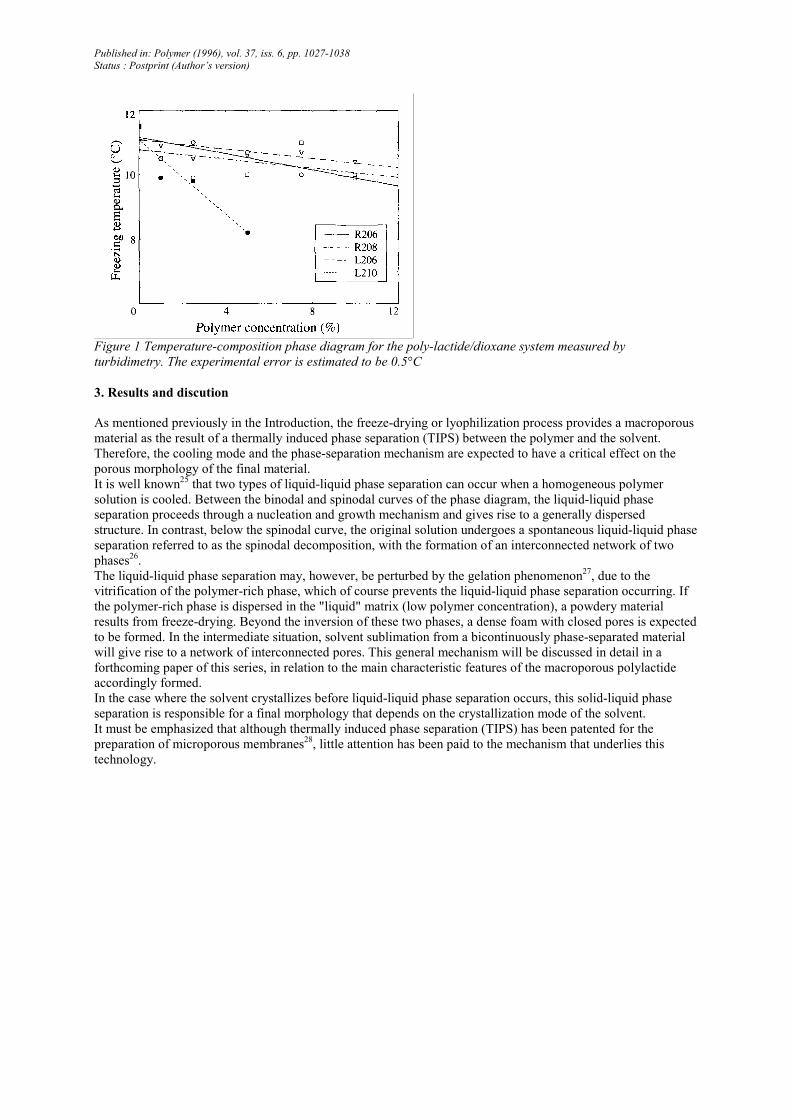
Figure 1 Temperature-composition phase diagram for the poly-lactide/dioxane system measured by
turbidimetry. The experimental error is estimated to be 0.5°C
3. Results and discution
As mentioned previously in the Introduction, the freeze-drying or lyophilization process provides a macroporous
material as the result of a thermally induced phase separation (TIPS) between the polymer and the solvent.
Therefore, the cooling mode and the phase-separation mechanism are expected to have a critical effect on the
porous morphology of the final material.
It is well known25 that two types of liquid-liquid phase separation can occur when a homogeneous polymer
solution is cooled. Between the binodal and spinodal curves of the phase diagram, the liquid-liquid phase
separation proceeds through a nucleation and growth mechanism and gives rise to a generally dispersed
structure. In contrast, below the spinodal curve, the original solution undergoes a spontaneous liquid-liquid phase
separation referred to as the spinodal decomposition, with the formation of an interconnected network of two
phases26.
The liquid-liquid phase separation may, however, be perturbed by the gelation phenomenon27, due to the
vitrification of the polymer-rich phase, which of course prevents the liquid-liquid phase separation occurring. If
the polymer-rich phase is dispersed in the "liquid" matrix (low polymer concentration), a powdery material
results from freeze-drying. Beyond the inversion of these two phases, a dense foam with closed pores is expected
to be formed. In the intermediate situation, solvent sublimation from a bicontinuously phase-separated material
will give rise to a network of interconnected pores. This general mechanism will be discussed in detail in a
forthcoming paper of this series, in relation to the main characteristic features of the macroporous polylactide
accordingly formed.
In the case where the solvent crystallizes before liquid-liquid phase separation occurs, this solid-liquid phase
separation is responsible for a final morphology that depends on the crystallization mode of the solvent.
It must be emphasized that although thermally induced phase separation (TIPS) has been patented for the
preparation of microporous membranes28, little attention has been paid to the mechanism that underlies this
technology.
Published in: Polymer (1996), vol. 37, iss. 6, pp. 1027-1038
Status : Postprint (Author’s version)
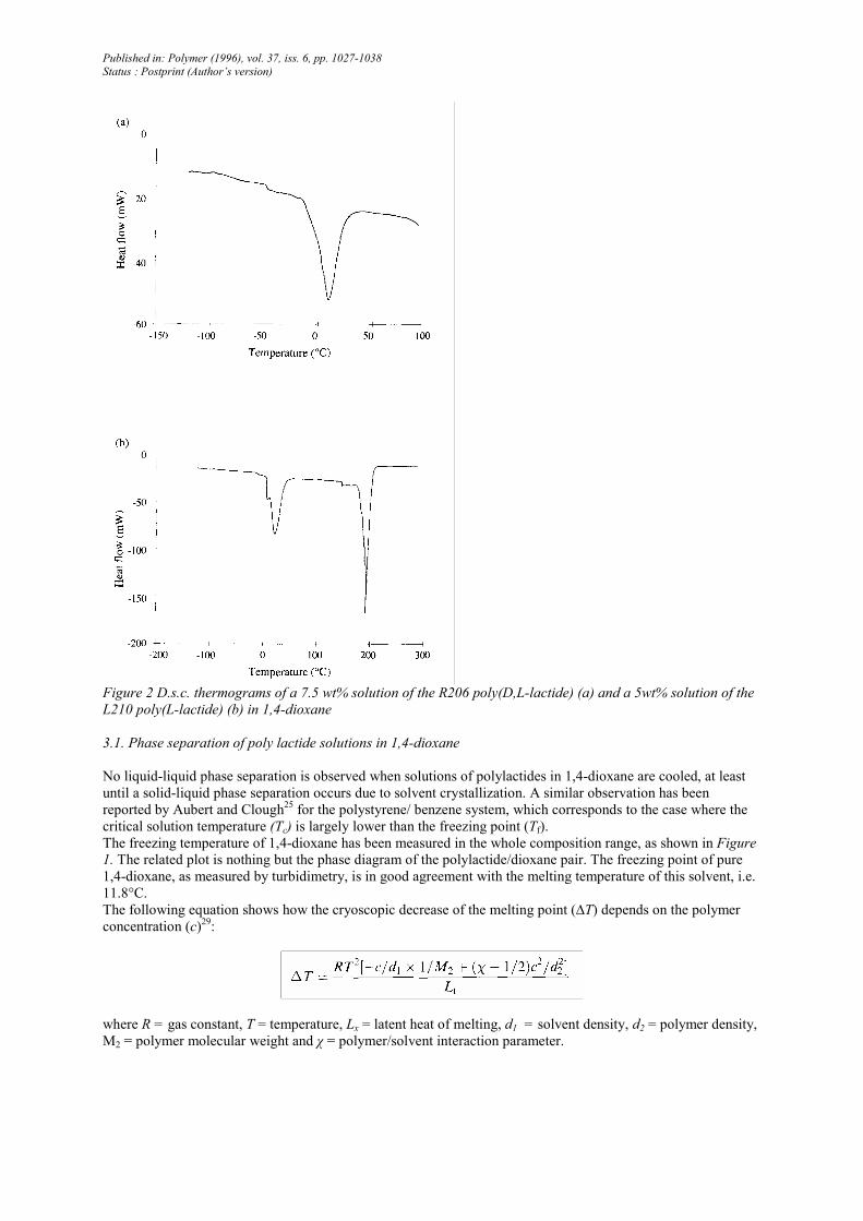
Figure 2 D.s.c. thermograms of a 7.5 wt% solution of the R206 poly(D,L-lactide) (a) and a 5wt% solution of the
L210 poly(L-lactide) (b) in 1,4-dioxane
3.1. Phase separation of poly lactide solutions in 1,4-dioxane
No liquid-liquid phase separation is observed when solutions of polylactides in 1,4-dioxane are cooled, at least
until a solid-liquid phase separation occurs due to solvent crystallization. A similar observation has been
reported by Aubert and Clough25 for the polystyrene/ benzene system, which corresponds to the case where the
critical solution temperature (Tc) is largely lower than the freezing point (Tf).
The freezing temperature of 1,4-dioxane has been measured in the whole composition range, as shown in Figure
1. The related plot is nothing but the phase diagram of the polylactide/dioxane pair. The freezing point of pure
1,4-dioxane, as measured by turbidimetry, is in good agreement with the melting temperature of this solvent, i.e.
11.8°C.
The following equation shows how the cryoscopic decrease of the melting point (∆T) depends on the polymer
concentration (c)29:
where R = gas constant, T = temperature, Lx = latent heat of melting, d1 = solvent density, d2 = polymer density,
M2 = polymer molecular weight and χ = polymer/solvent interaction parameter.
Published in: Polymer (1996), vol. 37, iss. 6, pp. 1027-1038
Status : Postprint (Author’s version)
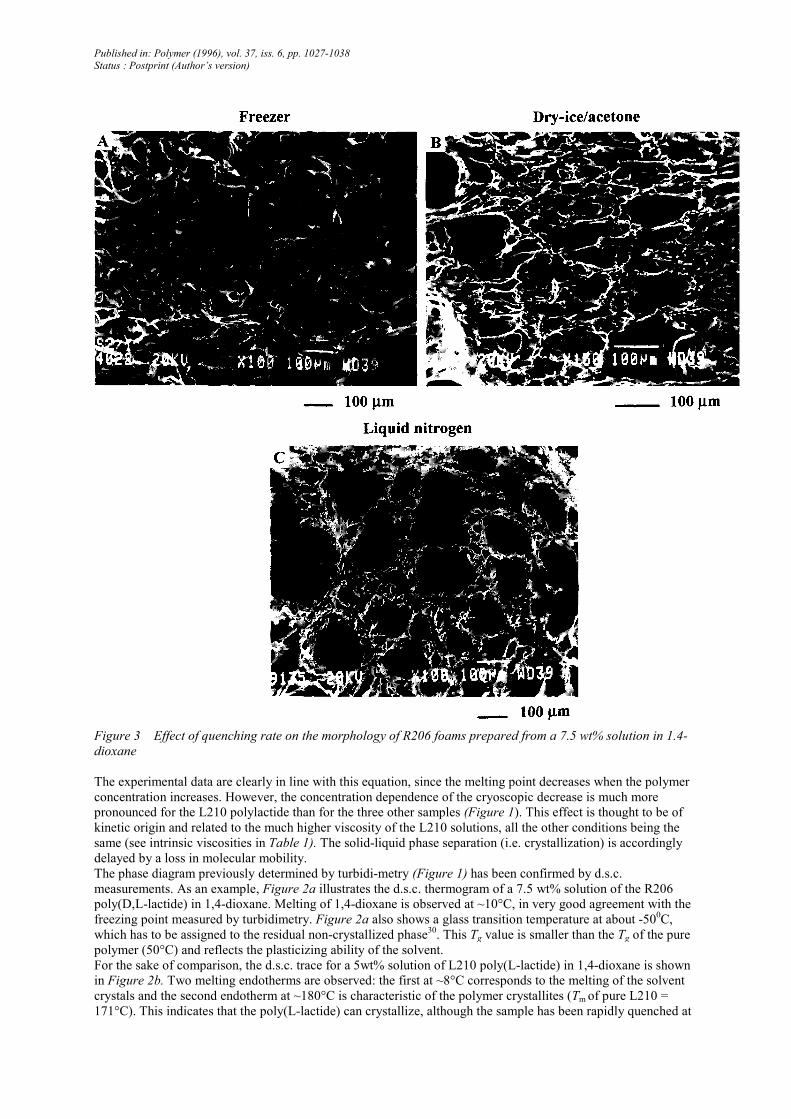
Figure 3 Effect of quenching rate on the morphology of R206 foams prepared from a 7.5 wt% solution in 1.4-
dioxane
The experimental data are clearly in line with this equation, since the melting point decreases when the polymer
concentration increases. However, the concentration dependence of the cryoscopic decrease is much more
pronounced for the L210 polylactide than for the three other samples (Figure 1). This effect is thought to be of
kinetic origin and related to the much higher viscosity of the L210 solutions, all the other conditions being the
same (see intrinsic viscosities in Table 1). The solid-liquid phase separation (i.e. crystallization) is accordingly
delayed by a loss in molecular mobility.
The phase diagram previously determined by turbidi-metry (Figure 1) has been confirmed by d.s.c.
measurements. As an example, Figure 2a illustrates the d.s.c. thermogram of a 7.5 wt% solution of the R206
poly(D,L-lactide) in 1,4-dioxane. Melting of 1,4-dioxane is observed at ~10°C, in very good agreement with the
freezing point measured by turbidimetry. Figure 2a also shows a glass transition temperature at about -500C,
which has to be assigned to the residual non-crystallized phase30. This Tg value is smaller than the Tg of the pure
polymer (50°C) and reflects the plasticizing ability of the solvent.
For the sake of comparison, the d.s.c. trace for a 5wt% solution of L210 poly(L-lactide) in 1,4-dioxane is shown
in Figure 2b. Two melting endotherms are observed: the first at ~8°C corresponds to the melting of the solvent
crystals and the second endotherm at ~180°C is characteristic of the polymer crystallites (Tm of pure L210 =
171°C). This indicates that the poly(L-lactide) can crystallize, although the sample has been rapidly quenched at
Published in: Polymer (1996), vol. 37, iss. 6, pp. 1027-1038
Status : Postprint (Author’s version)
the liquid nitrogen temperature in order to mimic the freeze-drying process. Consistently, a L210 foam prepared
by freeze-drying a 5 wt% solution in 1,4-dioxane exhibits a degree of crystallinity of ~20%.
3.2. Preparation of polylactide foams by freeze-drying
Several authors have reported that the porosity of foams prepared by freeze-drying depends on the quenching
rate of the original homogeneous polymer solution20, 22, 25
.
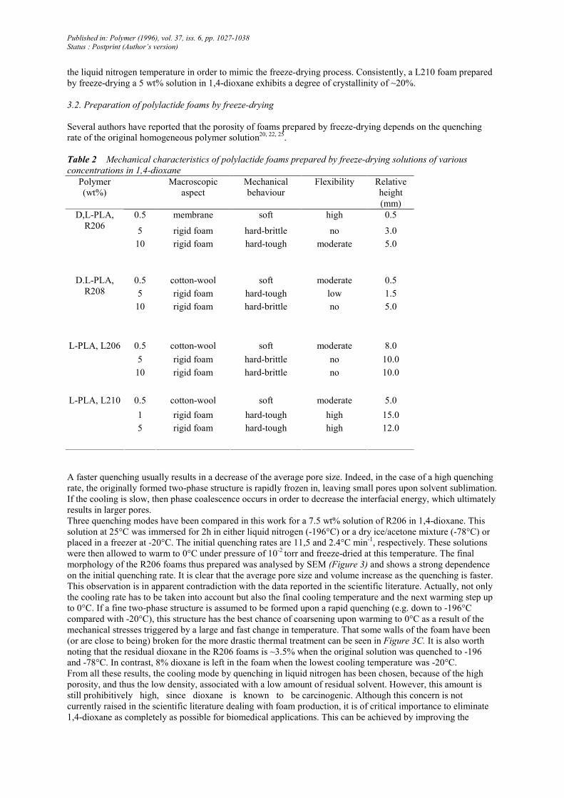
Table 2 Mechanical characteristics of polylactide foams prepared by freeze-drying solutions of various
concentrations in 1,4-dioxane
Polymer
(wt%)
Macroscopic
aspect
Mechanical
behaviour
Flexibility Relative
height
(mm)
0.5 membrane soft high 0.5
5 rigid foam hard-brittle no 3.0
D,L-PLA,
R206
10 rigid foam hard-tough moderate 5.0
0.5 cotton-wool soft moderate 0.5
5 rigid foam hard-tough low 1.5
D.L-PLA,
R208
10 rigid foam hard-brittle no 5.0
0.5 cotton-wool soft moderate 8.0
5 rigid foam hard-brittle no 10.0
L-PLA, L206
10 rigid foam hard-brittle no 10.0
0.5 cotton-wool soft moderate 5.0
1 rigid foam hard-tough high 15.0
L-PLA, L210
5 rigid foam hard-tough high 12.0
A faster quenching usually results in a decrease of the average pore size. Indeed, in the case of a high quenching
rate, the originally formed two-phase structure is rapidly frozen in, leaving small pores upon solvent sublimation.
If the cooling is slow, then phase coalescence occurs in order to decrease the interfacial energy, which ultimately
results in larger pores.
Three quenching modes have been compared in this work for a 7.5 wt% solution of R206 in 1,4-dioxane. This
solution at 25°C was immersed for 2h in either liquid nitrogen (-196°C) or a dry ice/acetone mixture (-78°C) or
placed in a freezer at -20°C. The initial quenching rates are 11,5 and 2.4°C min-1, respectively. These solutions
were then allowed to warm to 0°C under pressure of 10-2 torr and freeze-dried at this temperature. The final
morphology of the R206 foams thus prepared was analysed by SEM (Figure 3) and shows a strong dependence
on the initial quenching rate. It is clear that the average pore size and volume increase as the quenching is faster.
This observation is in apparent contradiction with the data reported in the scientific literature. Actually, not only
the cooling rate has to be taken into account but also the final cooling temperature and the next warming step up
to 0°C. If a fine two-phase structure is assumed to be formed upon a rapid quenching (e.g. down to -196°C
compared with -20°C), this structure has the best chance of coarsening upon warming to 0°C as a result of the
mechanical stresses triggered by a large and fast change in temperature. That some walls of the foam have been
(or are close to being) broken for the more drastic thermal treatment can be seen in Figure 3C. It is also worth
noting that the residual dioxane in the R206 foams is ~3.5% when the original solution was quenched to -196
and -78°C. In contrast, 8% dioxane is left in the foam when the lowest cooling temperature was -20°C.
From all these results, the cooling mode by quenching in liquid nitrogen has been chosen, because of the high
porosity, and thus the low density, associated with a low amount of residual solvent. However, this amount is
still prohibitively high, since dioxane is known to be carcinogenic. Although this concern is not
currently raised in the scientific literature dealing with foam production, it is of critical importance to eliminate
1,4-dioxane as completely as possible for biomedical applications. This can be achieved by improving the
Published in: Polymer (1996), vol. 37, iss. 6, pp. 1027-1038
Status : Postprint (Author’s version)
freeze-drying conditions in terms of the reduced pressure and the solvent sublimation time.
3.3. Mechanical resistance of the freeze-dried polylactide foams
Table 2 summarizes the behaviour of the freeze-dried foams under hand-applied deformations. Depending on the
response to flexure, the material is classified as tough or brittle, while it is said to be hard or soft in relation to its
resistance to pressure. On the basis of these qualitative observations, the various foams that have been prepared
can be easily discriminated from each other and subdivided into two main classes: the "cotton-wool-like"
materials that are soft and non-tough and prepared from dilute solutions (0.5wt%), and the "rigid" foams that
originate from higher concentration solutions (5-10wt%) and are hard, tough or brittle. The effect of the initial
polymer concentration on the mechanical behaviour of the foams is clearly observed. Interestingly enough, a 1
wt% solution of the high-molecular-weight poly(L-lactide) (L210) gives rise to foams that advantageously
combine softness and toughness. Semicrystalline poly(L-lactide)s and amorphous poly(D,L-lactide)s can be
distinguished by the relative height reached by the system after foaming, all the other conditions being the same.
Thus, the poly(L-lactide) foams are approximately one order of magnitude more expanded than the poly(D,L-
lactide) foams (comparison of R208 0.5% and L210 0.5% in Table 2). This effect is consistent with the poly(L-
lactide) crystallization that stabilizes the porous structure when the frozen dioxane is sublimated off.
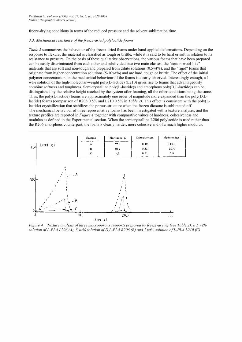
The mechanical behaviour of three representative foams has been investigated with a texture analyser, and the
texture profiles are reported in Figure 4 together with comparative values of hardness, cohesiveness and
modulus as defined in the Experimental section. When the semicrystalline L206 polylactide is used rather than
the R206 amorphous counterpart, the foam is clearly harder, more cohesive and of a much higher modulus.
Figure 4 Texture analysis of three macroporous supports prepared by freeze-drying (see Table 2): a 5 wt%
solution of L-PLA L206 (A), 5 wt% solution of D,L-PLA R206 (B) and 1 wt% solution of L-PLA L210 (C)
Published in: Polymer (1996), vol. 37, iss. 6, pp. 1027-1038
Status : Postprint (Author’s version)
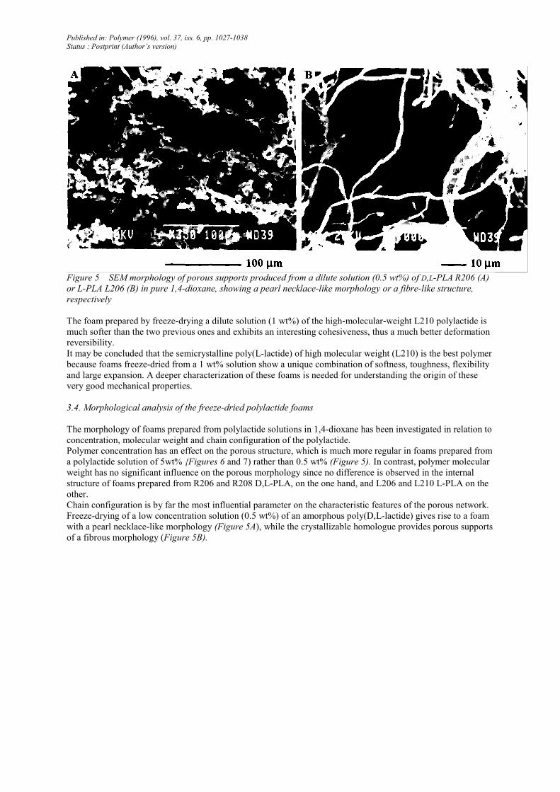
Figure 5 SEM morphology of porous supports produced from a dilute solution (0.5 wt%) of D,L-PLA R206 (A)
or L-PLA L206 (B) in pure 1,4-dioxane, showing a pearl necklace-like morphology or a fibre-like structure,
respectively
The foam prepared by freeze-drying a dilute solution (1 wt%) of the high-molecular-weight L210 polylactide is
much softer than the two previous ones and exhibits an interesting cohesiveness, thus a much better deformation
reversibility.
It may be concluded that the semicrystalline poly(L-lactide) of high molecular weight (L210) is the best polymer
because foams freeze-dried from a 1 wt% solution show a unique combination of softness, toughness, flexibility
and large expansion. A deeper characterization of these foams is needed for understanding the origin of these
very good mechanical properties.
3.4. Morphological analysis of the freeze-dried polylactide foams
The morphology of foams prepared from polylactide solutions in 1,4-dioxane has been investigated in relation to
concentration, molecular weight and chain configuration of the polylactide.
Polymer concentration has an effect on the porous structure, which is much more regular in foams prepared from
a polylactide solution of 5wt% {Figures 6 and 7) rather than 0.5 wt% (Figure 5). In contrast, polymer molecular
weight has no significant influence on the porous morphology since no difference is observed in the internal
structure of foams prepared from R206 and R208 D,L-PLA, on the one hand, and L206 and L210 L-PLA on the
other.
Chain configuration is by far the most influential parameter on the characteristic features of the porous network.
Freeze-drying of a low concentration solution (0.5 wt%) of an amorphous poly(D,L-lactide) gives rise to a foam
with a pearl necklace-like morphology (Figure 5A), while the crystallizable homologue provides porous supports
of a fibrous morphology (Figure 5B).
Published in: Polymer (1996), vol. 37, iss. 6, pp. 1027-1038
Status : Postprint (Author’s version)
Figure 6 SEM morphology of foams prepared by freeze-drying a 5 wt% solution of D,L-PLA R206 in 1,4-
dioxane
When the polymer concentration is increased up to 5 wt%, the D,L-PLA foams show a series of parallel tubes,
the diameter of which is in the range 100 to 200 µm (transverse cross-section shown in Figures 6A and B). The
internal wall of these channels is also macroporous (Figure 6C) in the range 10 to 20 µm and shows a ladder-like
structure (Figure 6D). As a whole, the same porous morphology is exhibited by the semicrystalline L-PLA
foams, with a higher degree of organization than the amorphous foams.
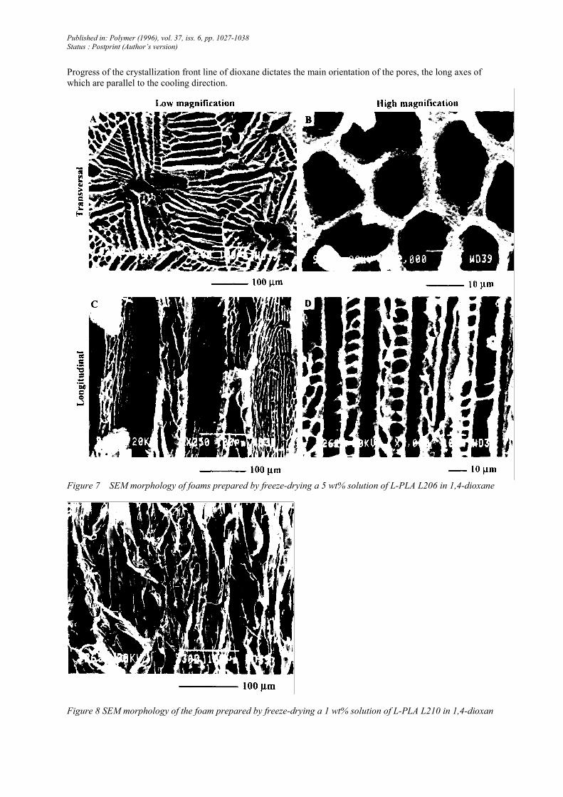
A transverse cross-section through an L206 foam prepared from a 5wt% solution in 1,4-dioxane shows a general
pattern of lamellae with a main radial orientation from a central hole (Figure 7A). Some interlamellar regions are
subdivided into pores, the diameter of which is ~10 µm (Figure 7B). A longitudinal cross-section (Figure 7C)
illustrates the long-range orientation of the porous channels made of parallel lamellae. A higher magnification
(Figure 7D) reveals the remarkable regularity and directionality of the pores with the ladder-like substructure of
the lamellae.
Although an isotropic porous morphology is usually desired, there are some instances where a high anisotropy in
the porous organization is a prerequisite, for instance when supports for nerve regeneration are considered31. The
remarkable anisotropy of the pore network and the ladder-like structure of the internal walls are observed
independently of the amorphous or semicrystalline character of the polylactide foams, even though partial
crystallization is clearly favourable to a higher degree of order and orientation in L-PLA foams. This observation
indicates that the difference reported in the porosity of D,L-PLA and L-PLA foams (Tables 2 and 3) is not to be
found in the phase-separation mechanism but rather in the stabilization of the porous structure by the crystal-
lizable L-PLA when the phase-separated system is freeze-dried.
Thus, the phase-separation mechanism is basically responsible for the characteristic features of the foam
morphology. No liquid-liquid phase separation is observed to occur until the solvent phase-separates by freezing.
Published in: Polymer (1996), vol. 37, iss. 6, pp. 1027-1038
Status : Postprint (Author’s version)
Progress of the crystallization front line of dioxane dictates the main orientation of the pores, the long axes of
which are parallel to the cooling direction.
Figure 7 SEM morphology of foams prepared by freeze-drying a 5 wt% solution of L-PLA L206 in 1,4-dioxane
Figure 8 SEM morphology of the foam prepared by freeze-drying a 1 wt% solution of L-PLA L210 in 1,4-dioxan
Published in: Polymer (1996), vol. 37, iss. 6, pp. 1027-1038
Status : Postprint (Author’s version)
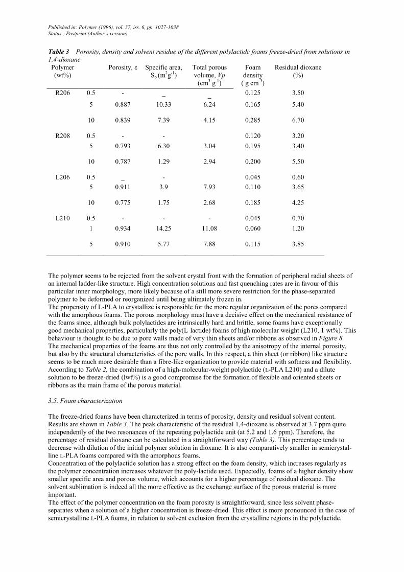
Table 3 Porosity, density and solvent residue of the different polylactidc foams freeze-dried from solutions in
1,4-dioxane
Polymer
(wt%)
Porosity, ε Specific area,
Sp (m2g-1)
Total porous
volume, Vp
(cm3 g
-1)
Foam
density
( g cm-3)
Residual dioxane
(%)
R206 0.5 - _ _ 0.125 3.50
5 0.887 10.33 6.24 0.165 5.40
10 0.839 7.39 4.15 0.285 6.70
R208 0.5 - - 0.120 3.20
5 0.793 6.30 3.04 0.195 3.40
10 0.787 1.29 2.94 0.200 5.50
L206 0.5 _ - 0.045 0.60
5 0.911 3.9 7.93 0.110 3.65
10 0.775 1.75 2.68 0.185 4.25
L210 0.5 - - - 0.045 0.70
1 0.934 14.25 11.08 0.060 1.20
5 0.910 5.77 7.88 0.115 3.85
The polymer seems to be rejected from the solvent crystal front with the formation of peripheral radial sheets of
an internal ladder-like structure. High concentration solutions and fast quenching rates are in favour of this
particular inner morphology, more likely because of a still more severe restriction for the phase-separated
polymer to be deformed or reorganized until being ultimately frozen in.
The propensity of L-PLA to crystallize is responsible for the more regular organization of the pores compared
with the amorphous foams. The porous morphology must have a decisive effect on the mechanical resistance of
the foams since, although bulk polylactides are intrinsically hard and brittle, some foams have exceptionally
good mechanical properties, particularly the poly(L-lactide) foams of high molecular weight (L210, 1 wt%). This
behaviour is thought to be due to pore walls made of very thin sheets and/or ribbons as observed in Figure 8.
The mechanical properties of the foams are thus not only controlled by the anisotropy of the internal porosity,
but also by the structural characteristics of the pore walls. In this respect, a thin sheet (or ribbon) like structure
seems to be much more desirable than a fibre-like organization to provide material with softness and flexibility.
According to Table 2, the combination of a high-molecular-weight polylactide (L-PLA L210) and a dilute
solution to be freeze-dried (lwt%) is a good compromise for the formation of flexible and oriented sheets or
ribbons as the main frame of the porous material.
3.5. Foam characterization
The freeze-dried foams have been characterized in terms of porosity, density and residual solvent content.
Results are shown in Table 3. The peak characteristic of the residual 1,4-dioxane is observed at 3.7 ppm quite
independently of the two resonances of the repeating polylactide unit (at 5.2 and 1.6 ppm). Therefore, the
percentage of residual dioxane can be calculated in a straightforward way (Table 3). This percentage tends to
decrease with dilution of the initial polymer solution in dioxane. It is also comparatively smaller in semicrystal-
line L-PLA foams compared with the amorphous foams.
Concentration of the polylactide solution has a strong effect on the foam density, which increases regularly as
the polymer concentration increases whatever the poly-lactide used. Expectedly, foams of a higher density show
smaller specific area and porous volume, which accounts for a higher percentage of residual dioxane. The
solvent sublimation is indeed all the more effective as the exchange surface of the porous material is more
important.
The effect of the polymer concentration on the foam porosity is straightforward, since less solvent phase-
separates when a solution of a higher concentration is freeze-dried. This effect is more pronounced in the case of
semicrystalline L-PLA foams, in relation to solvent exclusion from the crystalline regions in the polylactide.
Published in: Polymer (1996), vol. 37, iss. 6, pp. 1027-1038
Status : Postprint (Author’s version)
Comparison of the amorphous (R206/R208) and semicrystalline (L206/L210) foams prepared under the same
concentration (5wt% solutions) gives some evidence for the effect of the polymer molecular weight (Table 3).
Specific area and porous volume decrease as the poly(D,L-lactide) molecular weight is increased. This
observation does not hold when the molecular weight of poly(L-lactide) is considered. Indeed, the two semicrys-
talline foams (L206, 5wt%/L210, 5wt%) exhibit the same characteristics, except for the specific area, which is
much higher for the L210 foam (5.77 m2 g
-1) than for the L206 foam (3.9 m
2 g-1). This result can actually be
accounted for by the pore size distribution which shows a population of micropores < l µm in the L210 foams,
while the porosity in the L206 foams is > 1 µm. The situation is still more striking when the R208 and R206
amorphous foams are compared.
The effect of chain stereoregularity may be found in the comparison of foams prepared from an amorphous and
semicrystalline polylactide of the same molecular weight and used at the same concentration (i.e. R206 and
L206: 5wt%; R208 and L210: 5wt%). It appears from Table 3 that the L-PLA foams are less dense and contain
less residual dioxane than the D,L-PLA supports. This observation is in line with a larger porosity (ε), a higher
total porous volume (Vp) and a lower specific area (Sp) for foams freeze-dried from the poly(L-lactide) solutions
rather than poly(D,L-lactide) ones.
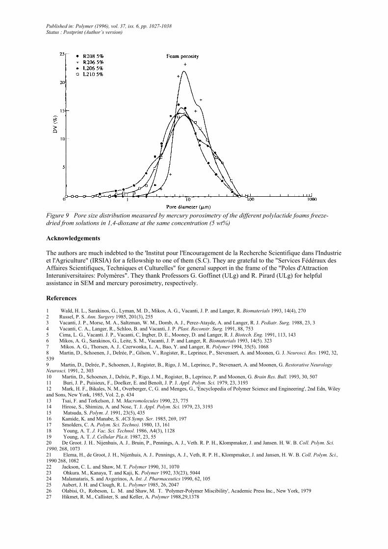
Although the pore diameter at the maximum of the pore size distribution curves (Figure 9) is essentially
independent of molecular weight and chain configuration of the polylactide, the broadness of this distribution
increases with molecular weight (from R206 and L206 to R208 and L210) and chain stereoregularity at constant
molecular weight (from R206 to L206 and from R208 to L210). This observation indicates that 1,4-dioxane
forms crystallites of a nearly constant average size upon cooling and that this process is increasingly although
moderately perturbed when the liquid-separated phase is more viscous (PLA of a higher molecular weight) or
prone to crystallize. It is thus clear that the molecular characteristics of the polylactide have no decisive effect on
the overall porosity of the foams. Crystallization of 1,4-dioxane in relation to the cooling conditions (rates)
remains the most influential parameter.
4. Conclusions
The solid-liquid phase separation of solutions of poly(D,L-lactide) and poly(L-lactide) in 1,4-dioxane
allows for the production of macroρorous foams of a high anisotropy.
Macropores with an average diameter of 100 µm are organized in bundles of channels in the ρolylactide matrix,
responsible for the anisotropy of the porous structure. A porous substructure in the walls of the pores is observed
at a 10 times smaller scale, providing them with a ladder morphology. Although this general porous structure is
observed for both the amorphous and semicrystalline foams, it is more regular and better organized for the
stereoregular poly(L-lactide). This means that crystallization of 1,4-dioxane as the solid-liquid phase separation
occurs is the most influential parameter on the foam morphology. Pores are nothing but the fingerprints of
dioxane crystallites.
Porosity and density of the foam and residual solvent are strongly dependent on the initial concentration of
polylactide in dioxane. Upon increasing the concentration, the foam density and the amount of residual dioxane
increase, while the foam porosity decreases. Although these characteristic features are not deeply modified by
the polymer molecular weight, they change with the ability of the polylactide to crystallize. Semicrystalline
foams are indeed more porous, less dense and contain less residual dioxane than the amorphous counterparts.
The porous support prepared from a 1 wt% solution of L210 in dioxane is the best one, because it combines a
high porosity (93%), a low density (0.060 g cm-3) and a low dioxane residue (1%) with a good mechanical
resistance and a high flexibility. This mechanical behaviour might be accounted for by the formation of very thin
sheets or ribbons of ρoly(L-lactide). All the other foams are usually more rigid and brittle in relation to the
formation of thicker lamellae.
Published in: Polymer (1996), vol. 37, iss. 6, pp. 1027-1038
Status : Postprint (Author’s version)
Figure 9 Pore size distribution measured by mercury porosimetry of the different polylactide foams freeze-
dried from solutions in 1,4-dioxane at the same concentration (5 wt%)
Acknowledgements
The authors are much indebted to the 'Institut pour l'Encouragement de la Recherche Scientifique dans l'Industrie
et l'Agriculture" (IRSIA) for a fellowship to one of them (S.C). They are grateful to the "Services Fédéraux des
Affaires Scientifiques, Techniques et Culturelles" for general support in the frame of the "Poles d'Attraction
Interuniversitaires: Polymères". They thank Professors G. Goffinet (ULg) and R. Pirard (ULg) for helpful
assistance in SEM and mercury porosimetry, respectively.
References
1 WaId, H. L., Sarakinos, G., Lyman, M. D., Mikos, A. G., Vacanti, J. P. and Langer, R. Biomaterials 1993, 14(4), 270
2 Russel, P. S. Ann. Surgery 1985, 201(3), 255 3 Vacanti, J. P., Morse, M. A., Saltzman, W. M., Domb, A. J., Perez-Atayde, A. and Langer, R. J. Pediatr. Surg. 1988, 23, 3
4 Vacanti, C. A., Langer, R., Schloo, B. and Vacanti, J. P. Plast. Reconstr. Surg. 1991, 88, 753
5 Cima, L. G., Vacanti. J. P., Vacanti, C, Ingber, D. E., Mooney, D. and Langer, R. J. Biotech. Eng. 1991, 113, 143 6 Mikos, A. G., Sarakinos, G., Leite, S. M., Vacanti, J. P. and Langer, R. Biomaterials 1993, 14(5). 323
7 Mikos. A. G., Thorsen, A. J.. Czerwonka, L. A., Bao, Y. and Langer, R. Polymer 1994, 35(5). 1068
8 Martin, D., Schoenen, J., Delrée, P., Gilson, V., Rogister, R., Leprince, P., Stevenaert, A. and Moonen, G. J. Neurosci. Res. 1992, 32, 539
9 Martin, D., Delrée, P., Schoenen, J., Rogister, B., Rigo, J. M., Leprince, P., Stevenaert, A. and Moonen, G. Restorative Neurology Neurosci. 1991, 2, 303
10 Martin, D., Schoenen, J., Delrée, P., Rigo, J. M., Rogister, B., Leprince, P. and Moonen, G. Brain Res. Bull. 1993, 30, 507
11 Buri, J. P., Puisieux, F., Doelker, E. and Benoît, J. P. J. Appl. Polym. Sci. 1979, 23, 3193 12 Mark, H. F., Bikales, N. M., Overberger, C, G. and Menges, G., 'Encyclopedia of Polymer Science and Engineering', 2nd Edn, Wiley
and Sons, New York, 1985, Vol. 2, p. 434
13 Tsai, F. and Torkelson, J. M. Macromolecules 1990, 23, 775 14 Hirose, S., Shimizu, A. and Nose, T. J. Appl. Polym. Sci. 1979, 23, 3193
15 Matsuda, S. Polym. J. 1991, 23(5), 435
16 Kamide, K. and Manabe, S. ACS Symp. Ser. 1985, 269, 197 17 Smolders, C. A. Polym. Sci. Techno). 1980, 13, 161
18 Young, A. T. J. Vac. Sci. Technol. 1986, A4(3), 1128
19 Young, A. T. J. Cellular Pla.it. 1987, 23, 55 20 De Groot. J. H.. Nijenhuis, A. J.. Bruin, P., Pennings, A. J., Veth. R. P. H., Klompmaker, J. and Jansen. H. W. B. Coll. Pυlym. Sci.
1990, 268, 1073
21 Elema, H., de Groot, J. H., Nijenhuis, A. J.. Pennings, A. J., Veth, R. P. H., Klompmaker, J. and Jansen, H. W. B. Coll. Polym. Sci., 1990 268, 1082
22 Jackson, C. L. and Shaw, M. T. Polymer 1990, 31, 1070
23 Ohkura. M., Kanaya, T. and Kaji, K. Polymer 1992, 33(23), 5044 24 Malamataris, S. and Avgerinos, A. Int. J. Pharmaceutics 1990, 62, 105
25 Aubert, J. H. and Clough, R. L. Polymer 1985, 26, 2047
26 Olabisi, O., Robeson, L. M. and Shaw, M. T. 'Polymer-Polymer Miscibility', Academic Press Inc., New York, 1979 27 Hikmet, R. M., Callister, S. and Keller, A. Polymer 1988,29,1378
Published in: Polymer (1996), vol. 37, iss. 6, pp. 1027-1038
Status : Postprint (Author’s version)
28 Castro, A. J. US Patent 4247498, 24 November 1978
29 Kim, S. S. and Lloyd. D. R. Polymer 1992, 33(5), 1026
30 Hatley, R. H. M. Develop. Biol. Standard 1991, 74, 105 31 Fields, R. D., Le Beau, J. M., Longo, F. M. and Ellisman, M. H. Progr. Neurobiol. 1989, 33, 87