SHIELDED BAG TEST SYSTEM
Model 4431-T (Turnkey Voltage & Energy System)
Operating Manual
10/13

1
IMPORTANT SAFETY INSTRUCTIONS
(Equipment containing HV)
The equipment described in this Manual is designed and manufactured to operate within defined design limits. Any misuse may result in electric shock or fire. To prevent the equipment from being damaged, the following rules should be observed for installation, use and maintenance. Read the following safety instructions before operating the instrument. Retain these instructions in a safe place for future reference.
POWER
POWER CORD: Use only the power cord specified for this equipment and certified for the country of use. If the power (mains) plug is replaced, follow the wiring connections specified for the country of use. When installing or removing the power plug hold the plug, not the cord.
The power cord provided is equipped with a 3-prong grounded plug (a plug with a third grounding pin). This is both a safety feature to avoid electrical shock and a requirement for correct equipment operation. If the outlet to be used does not accommodate the 3-prong plug, either change the outlet or use a grounding adapter.
FUSES: Replace fuses only with those having the required current rating, voltage and specified type such as normal blow, time delay, etc. DO NOT use makeshift fuses or short the fuse holder. This could cause a shock or fire hazard or severely damage the instrument.
POWER LINE VOLTAGE (MAINS): If the line (mains) voltage is changed or isolated by an autotransformer the common terminal must be connected to the ground (earth) terminal of the power source.
OPERATION
CAUTION
Equipment designed to simulate a high voltage electrostatic discharge such as the Series 900 ESD Simulators, Model 4431 Shielded Bag Test System and the Model 4046 Static Decay Meter utilize voltages up to 30kV. The basic nature of an ESD event will result in electromagnetic radiation in addition to the high level, short duration current pulse. Therefore, personnel with a heart pacemaker must not operate the instrument or be in the vicinity while it is being used.
DO NOT OPERATE WITH COVERS OR PANELS REMOVED. Voltages inside the Model 4431 can be as high as 2kV. In addition, equipment may contain capacitors up to 200pF charged to 1kV. Capacitors can retain a charge even if the equipment is turned off.
DO NOT OPERATE WITH SUSPECTED EQUIPMENT FAILURES. If any odor or smoke becomes apparent turn off the equipment and unplug it immediately. Failure to do so may

2
result in electrical shock, fire or permanent damage to the equipment. Contact the factory for further instructions.
DO NOT OPERATE IN WET/DAMP CONDITIONS: If water or other liquid penetrates the equipment, unplug the power cord and contact the factory for further instructions. Continuous use in this case may result in electrical shock, fire or permanent damage to the equipment.
DO NOT OPERATE IN HIGH HUMIDITY: Operating the equipment in high humidity conditions will cause deteriation in performance, system failure, or present a shock or fire hazard. Contact the factory for further instructions.
DO NOT OPERATE IN AREAS WITH HEAVY DUST: Operating the equipment in high dust conditions will cause deteriation in performance, system failure, or present a shock or fire hazard. Contact the factory for further instructions.
DO NOT OPERATE IN AN EXPLOSIVE ATMOSPHERE: Operating the equipment in the presence of flammable gases or fumes constitutes a definite safety hazard. For equipment designed to operate in such environments the proper safety devices must be used such as dry air or inert gas purge, intrinsic safe barriers and/or explosion-proof enclosures.
DONOT USE IN ANY MANNER NOT SPECIFIED OR APPROVED BY THE MANUFACTURER: Unapproved use may result in damage to the equipment or present an electrical shock or fire hazard.
MAINTENANCE and SERVICE
CLEANING: Keep surfaces clean and free from dust or other contaminants. Such contaminants can have an adverse affect on system performance or result in electrical shock or fire. To clean use a damp cloth. Let dry before use. Do not use detergent, alcohol or antistatic cleaner as these products may have an adverse affect on system performance.
SERVICE: Do not attempt to repair or service the instrument yourself unless instructed by the factory to do so. Opening or removing the covers may expose you to high voltages, charged capacitors, electric shock and other hazards. If service or repair is required, contact the factory.
3
1.0 INTRODUCTION
The rapid advancement in the electronics industry during the past decade has placed increasing importance on the understanding of electrostatics and its effect on electronic devices and systems. Electrostatic Discharge (ESD) is a common cause of microelectronic circuit failure. Many of these devices can be seriously damaged or destroyed by an electrostatic discharge below 30 Volts, or as a result of an electrostatic field of only a few hundred Volts.
The static shielding bag was developed to provide a package that would protect static sensitive components placed inside from external ESD events. Many different bag constructions are now available that, when properly used, provide a Faraday cage (electrostatic field attenuation) around the objects placed inside.
The most common bags are constructed from transparent polyethylene film with a metalized layer of mylar laminated to either the outside or the inside of the bag. The metalized side is either on the outside (metal out) or buried between the mylar and the polyethylene film (metal in or buried metal layer). The metalized layer that provides the shield is usually aluminum or nickel with a thickness limited to approximately 100 Angstroms to maintain bag transparency. Other constructions are available, however, that consist of carbon grids or conductive fibers such as carbon or copper. Static shielding is also provided by nontransparent bags that are either carbon loaded polyethylene or foil laminated such as the MIL PRF 81705E Type I water vapor-proof shielded bag.
In selecting the correct bag for a given application, consideration must be given to whether the product being sensitive. The ability of the bag not to charge the object inside and the ability of the bag to dissipate any charge on its surface in a timely manner when grounded must also be taken into account.
Various commercial and military specifications and test standards now exist for evaluating the different electrical and physical characteristics of the bag and/or its material. The static dissipative characteristics of the bag material is determined by measuring the surface resistance in accordance with Electrostatic Discharge Association test standard ANSI/ESD S11.11. The antistatic (ability to resist tribocharging) characteristic is determined using procedures outlined in ESD ADV 11.21. The Electronics Industries Association Test Standard EIA 541-1988 "Packaging Material Standards - For The Protection Of ESD Sensitive Items" references test methods in place in 1988. However, ESD Association test standards developed since then are now specified.
The shielding effectiveness of the bag was previously evaluated using the voltage differential test method specified in EIA 541. However, the energy test method specified in ANSI/ESD S11.31 supersedes the voltage test and is now the specified test method. MIL PRF 81705E and ANSI/ESD S11.4 specify the ANSI/ESD S11.31 test. The ETS Model 4431-T Shielded Bag Test System meets the requirements of both test standards.

4
2.0 TEST METHODS
2.1 ANSI/ESD S11.31 ESD Association standard for evaluating the performance of electrostatic discharge shielding materials - Bags
This test method evaluates the performance of electrostatic discharge shielding bags. The purpose of this standard is to ensure that testing laboratories, using this test method to evaluate a given packaging material, will obtain similar results. This standard specifies the discharge waveform characteristics, probe configuration, probe capacitance and bag size. Figure 2.0-1 shows the generic schematic of the test system.
Figure 2.0-1: System generic schematic
Figure 2.0-2 shows the discharge current waveform requirement at the specified 1000 Volts when measured through a 500 Ohm resistor.
Figure 2.0-2: Discharge waveforms per ANSI/ESD STM5.1
The current pulse detected between the upper and lower electrodes of the capacitive probe is used to calculate the energy inside the bag by integrating the area under the curve as shown in Figure 2.0-3.

5
Figure 2.0-3: Typical Model 4431 shielded bag waveform
Six specimens of a given sample are required. Six measurements per specimen is specified. Testing is to be performed at both 12% and 50% ±3% RH at a temperature of 73 ±3°F after a conditioning period of 48 hours minimum. Bag size for this test is specified to be 8x10 inches (20x25 cm).
ANSI/ESD S11.31 specifies that the test conditions, peak current, minimum, maximum and average energy levels of all 36 measurements be reported for bag qualification.
2.2 ANSI/ESD S11.4 Static Control Bags
This standard defines the performance of static shielding bags used in manufacturing and commercial applications. It defines an acceptable bag as having <20nJ when tested in accordance with S11.31.
2.3 MIL PRF 81705E
This military standard defines the performance of Type 1 water-vapor proof and Type 3 static shielding bags. The acceptable energy limit when tested in accordance with S11.31 is <10nJ.
3.0 EQUIPMENT CONFIGURATIONS
3.1 Model 4431-T
The ETS Model 4431-T Shielded Bag Test System is supplied with a laptop computer as shown in Figures 3.0-1.

6
Figure 3.0-1: Model 4431-T Shielded Bag Test System
This is a turnkey system that performs both the ANSI/ESD S11.31 and the EIA 541-1998 shielding bag tests. Depending on the test method selected the System provides the correct discharge current pulse for both the ANSI/ESD S11.31 and EIA 541 tests. The capacitive sensor detects the current pulse or the voltage differential and sends the signal(s) to the included oscilloscope for detection and from the oscilloscope to the included computer for processing and calculation of energy; or attenuated voltage pulses from the direct connection to the 2-channel oscilloscope for the EIA 541 test.
The Model 4431-T Shielded Bag Test System consists of the following components:
3.1.1 Discharge Unit
1. High voltage power supply with separate ON/OFF switch, adjustable from approximately 850-1,250 Volts with 3½-digit LED display
2. Switched 100 & 200 pF and 1.5 and 400kOhm discharge networks 3. Mercury wetted discharge relay 4. Floating, programmable capacitive sensor consisting of two 0.875"
diameter precision ground stainless steel electrodes mounted in a 0.625" Delrin base with nominal capacitance of 6 pF
5. Built-in Tektronix CT-1 Current Transducer 6. 100:1 Voltage Attenuators for voltage differential test 7. Lever actuated stainless steel discharge and spring loaded ground
electrodes 8. Discharge electrode grounding relay to remove residual charge
between tests 9. Adjustable bag insertion stops for configuring the System for different
bag sizes per specification.
Note 1

7
10. Calibration jumper (Note 1: This cable no longer required)
1.1.2 Oscilloscope
1. Tektronix Model TDS2022C
3.1.2 Computer
1. Running 32-bit Operating System Windows 2000/XP/VISTA/7
3.1.3 Software
1. ETS Test Suit Manager, Energy Calculation Program (Version 4.0.3.3)
4.0 Discharge Unit Description
The Capacitive Sensor is a floating arm that contains the upper and lower electrodes, CT-1 current transducer and 500 Ohm resistor. Programming jacks located on both sides of the sensor arm allows the user to program the System for current or voltage measurements by inserting the pair of jumpers into the respective pair of .040 pin jacks as shown in Figure 4.0-1a and b.
a. Energy b. Voltage Differential
Figure 4.0-1: Capacitive sensor programming jumpers
The adjustable power supply allows the user to make minor corrections to obtain the specified discharge current and energy. A 3½-digit LED readout displays the discharge voltage. A switch on the front panel enables the user to turn off the high voltage when not in use. Note: Discharge switch will not work if high voltage is off. Multicolored LED point sources indicate CHARGE and DISCHARGE.
The FUNCTION switch is used to select MANual operation of ∆V, (Voltage differential per EIA 541 using either 400 or 1.5 kOhms) and nJ (Energy per ANSI/ESD STM11.31); or AUTO nJ. In the MAN mode the discharge pulse is initiated by either a front panel or a foot operated switch, which is convenient when testing in a humidity chamber. In the AUTO mode, the discharge sequence specified in ANSI/ESD S11.31 along with the scope settings are controlled automatically by the ETS Energy Calculation Program.
The discharge waveform generated by the Model 4431 meets the requirements of ANSI/ESD S5.1 Electrostatic Discharge Testing - Human Body Model. A typical discharge waveform measured with the discharge electrode in direct contact with the capacitive sensor is shown in Figure 4.0-2.
Programming Jumpers

8
Figure 4.0-2: Discharge waveform
A spring-loaded lever clamps the discharge electrode against the bag, capacitive sensor and spring loaded ground electrode with approximately 5 pounds of force, ensuring consistent and repeatable results.
Included with the Model 4431-T is the interconnect cables and accessories shown in Figure 4.0-3a:
Figure 4.0-3a: Model 4431-T cables and accessories
1. BNC-BNC (2) cables for connecting voltage output signals to oscilloscope 2. BNC cable from CT-1 to oscilloscope (Model 4431-T only) 3. 50 Ohm terminator 4. USB cable from computer to the oscilloscope (Model 4431-T only) 5. USB to serial converter with 9-pin sub-D from computer to communications
cable (Model 4431-T only) NOTE: Do not sustitute 6. 9-pin sub-D from Converter to 25-pin sub-D to Model 4431-T 7. Foot switch 8. IEC Line Cord (North American plug)
Figure 4.0-3b shows the jumpers and cables required to perform first time set up.
4 7
3
5
8
6
1
2

9
Figure 4.0-3b: Calibration cables and jumpers for first time set up
NOTE: If the Model 4431 is used to replace a Model 431 discharge unit an adapter is required to convert the 25-pin COMM PORT to a 3-pin DIN to receive its command signals from the computer’s PRINTER Parallel Port (Contact ETS). If the computer has only one output, it is necessary to install an A/B switch (supplied with early versions of the ETS Energy Calculation Program) to operate a printer.
The Model 4431 utilizes a universal switching power supply and may be operated directly from 90 - 260 VAC, 50/60 Hz line voltage (mains) with 0.5A resettable fuse that is reset by powering down the unit, and after several seconds turning it back on.
The latest version of the ETS Energy Calculation Program is written for PCs running
32-bit Operating System Windows 2000/XP/VISTA/7. This program controls the Model 4431-T, the Tektronix TDS2022C oscilloscope used to capture the waveform and the computer to generate a report containing all the data specified in ANSI/ESD S11.31 plus the verification and test data waveforms as shown in Figures 4.0-3 & 4.
5.0 SET-UP
Plug the AC line cord of the Model 4431 into a grounded outlet. This is a standard IEC cord with North American grounded plug. For non-North American locations, a line cord having the correct mains plug can be obtained from a local computer or electronics store. Otherwise, cut off the plug and install the appropriate plug for the location.
5.1 ANSI/ESD S11.31 Testing (Energy)
Refer to Figure 5.0-1 for the System set-up described below:
Cable to verify
discharge
waveform with
external CT-1
Shorting strap to
connect Dischg and
Capacitive
electrodes together
to measure 1kV
Dischg. waveform

10
Figure 5.0-1: System set up for Energy test
1. Connect the BNC connector from the built-in CT-1 current transducer into CH-1 of the oscilloscope. The Terminator provided must be used in order to match the 50 Ohm output impedance of the CT-1 to the 1 MegOhm impedance of the scope.
2. Connect the 25 pin – 9-pin cable to the USB – 9-pin adapter and 25-pin sub-D connector on the rear of the Model 4431
3. Connect the USB - USB cable to the 1st computer USB port and the other end to the USB-9-pin sub-D adapter.
2. Connect the USB – USB cable from the oscilloscope to the 2nd USB port on the computer (Note: Only connect after PC is on and finished booting. In case of miscommunication with the oscilloscope, unplug and re-plug it)
3. If a printer is used connect it to the 3rd USB port on the computer 4. Confirm that the red jumpers located on the sides of the capacitive sensor
are plugged in the center and front .040 pin jacks. This programs the capacitive sensor for current measurements.
5. Plug the phono plug from Foot Switch (only when unit is off), if used, into the REMOTE DISCHARGE jack on the rear panel of the Model 4431
6. Power up all instruments 7. Set the FUNCTION select switch to MAN nJ if the test is to be controlled by
the operator or to AUTO nJ if the test is to be controlled by the computer 8. For waveform verification in the MAN mode, set the oscilloscope VERTICAL
sensitivity to 500mV, the time base to 100nsec and the trigger level to 500mV. For bag testing start with settings of 20 or 50mV, 20nsec and 50 or 75mV respectively. Otherwise, the ETS Energy Calculation Program automatically sets the correct scope parameters.
5.2 EIA 541 (Voltage Differential)

11
Refer to Figure 5.0-2 for the set up for the voltage differential test.
Figure 5.0-2: Voltage differential test set up If the Model 4431-T is used to measure voltage differential, the CT-1 current sensor must be disconnected and the Voltage cables connected to perform this test. The Model 4431-T is shipped from the factory with the capacitive sensor programmed for the Energy test. To convert the System from energy to voltage differential, the capacitive sensor must first be converted by plugging the red jumpers into the center and rear pins as shown in Figure 5.0-3.
Figure: 5.0-3 Capacitive Sensor conversion from energy to voltage
5.2.1 R/C Networks
The user can select either of two R/C networks using the front panel FUNCTION selector switch. The commonly used 200pF discharged through 1500 Ohms or the EIA 541 specified 200pF discharged through 400 kOhms.
NOTE: The 1,500 Ohm resistor will enable bags having surface resistances between 10 and 100 kOhms (100 and 10,000 Ohms/sq) to be differentiated. On the other hand, the 400 kOhm resistor will only be able to differentiate bags having surface resistances between 1,000 ohms and 1 Megohm (10,000 and 10 MegOhms/sq). Current industry practice is to use 1,500 Ohms.
12
5.2.2 Oscilloscope
The oscilloscope and Discharge Unit must first be calibrated as a set. If the oscilloscope is supplied as part of the system, the Discharge Unit and scope will have already been calibrated. If the scope is provided by the user, it is first necessary to adjust the built in 100:1 attenuator amplitudes for equal amplitudes on each scope channel using the following procedure:
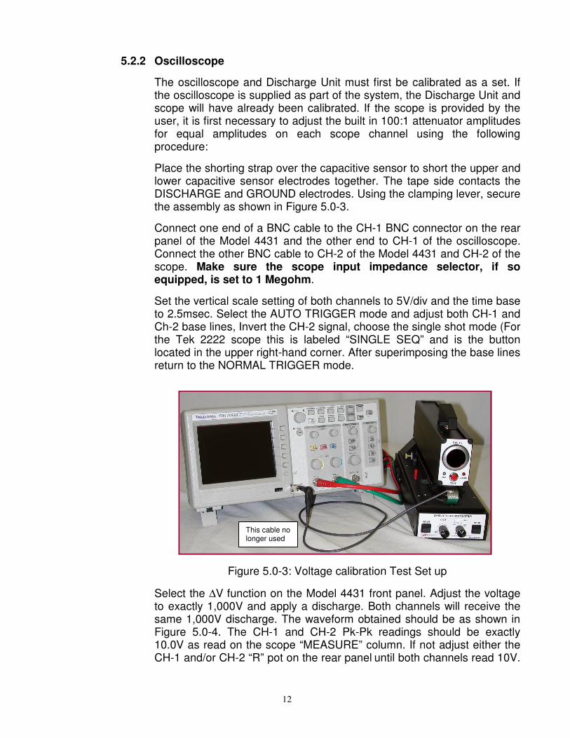
Place the shorting strap over the capacitive sensor to short the upper and lower capacitive sensor electrodes together. The tape side contacts the DISCHARGE and GROUND electrodes. Using the clamping lever, secure the assembly as shown in Figure 5.0-3.
Connect one end of a BNC cable to the CH-1 BNC connector on the rear panel of the Model 4431 and the other end to CH-1 of the oscilloscope. Connect the other BNC cable to CH-2 of the Model 4431 and CH-2 of the scope. Make sure the scope input impedance selector, if so equipped, is set to 1 Megohm.
Set the vertical scale setting of both channels to 5V/div and the time base to 2.5msec. Select the AUTO TRIGGER mode and adjust both CH-1 and Ch-2 base lines, Invert the CH-2 signal, choose the single shot mode (For the Tek 2222 scope this is labeled “SINGLE SEQ” and is the button located in the upper right-hand corner. After superimposing the base lines return to the NORMAL TRIGGER mode.
Figure 5.0-3: Voltage calibration Test Set up
Select the ∆V function on the Model 4431 front panel. Adjust the voltage to exactly 1,000V and apply a discharge. Both channels will receive the same 1,000V discharge. The waveform obtained should be as shown in Figure 5.0-4. The CH-1 and CH-2 Pk-Pk readings should be exactly 10.0V as read on the scope “MEASURE” column. If not adjust either the CH-1 and/or CH-2 “R” pot on the rear panel until both channels read 10V.
This cable no longer used
13
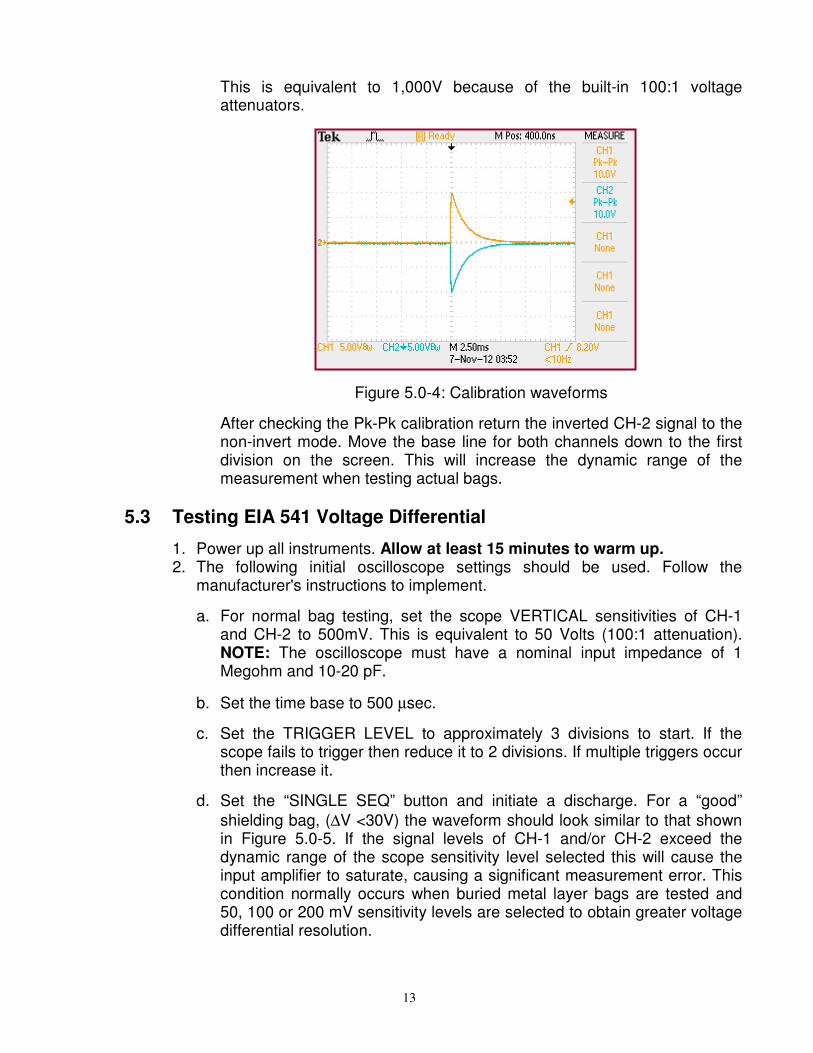
This is equivalent to 1,000V because of the built-in 100:1 voltage attenuators.
Figure 5.0-4: Calibration waveforms
After checking the Pk-Pk calibration return the inverted CH-2 signal to the non-invert mode. Move the base line for both channels down to the first division on the screen. This will increase the dynamic range of the measurement when testing actual bags.
5.3 Testing EIA 541 Voltage Differential
1. Power up all instruments. Allow at least 15 minutes to warm up. 2. The following initial oscilloscope settings should be used. Follow the
manufacturer's instructions to implement.
a. For normal bag testing, set the scope VERTICAL sensitivities of CH-1 and CH-2 to 500mV. This is equivalent to 50 Volts (100:1 attenuation). NOTE: The oscilloscope must have a nominal input impedance of 1 Megohm and 10-20 pF.
b. Set the time base to 500 µsec.
c. Set the TRIGGER LEVEL to approximately 3 divisions to start. If the scope fails to trigger then reduce it to 2 divisions. If multiple triggers occur then increase it.
d. Set the “SINGLE SEQ” button and initiate a discharge. For a “good”
shielding bag, (∆V <30V) the waveform should look similar to that shown in Figure 5.0-5. If the signal levels of CH-1 and/or CH-2 exceed the dynamic range of the scope sensitivity level selected this will cause the input amplifier to saturate, causing a significant measurement error. This condition normally occurs when buried metal layer bags are tested and 50, 100 or 200 mV sensitivity levels are selected to obtain greater voltage differential resolution.

14
Figure 5.0-5: Typical ∆V for a “good” bag (12V)
If the bag is “Bad” (∆V >30V) the waveforms will be similar to the one shown if Figure 5.0-6.
e. To obtain the differential voltage, manually subtract the CH-2 reading from the CH-1 reading. CAUTION: Do not use the MATH mode. The
waveforms contain high frequency noise. The math can calculate the ∆V of the noise signal instead of the actual discharge signal causing
erroneous ∆V readings.
Figure5.0-6: Typical ∆V for a “bad” bag (206V)
Another anomaly that can be observed is the resolution of the calculation. This is a function of the vertical scale setting. At 5V/div the resolution is 40mV (4V) for each channel. Since both channels are being looked at the same time, the total resolution becomes 2x40mV or 80mV (8V). At 1 &
2V/div the resolution of each channel is 20mV/div (4V). At ≥500mV/div the resolution is 10mV/div (2V) and at <500mV/div the resolution is

15
4mV/div (0.8V). The waveform shown for a good bag is at a scale setting
of exactly 500mV/div, hence the ∆V resolution is 2V. However, the TEK 2222 scope has a variable vertical scale setting instead of a fixed scale setting. The resolution can be increased by just setting the range scale of
both channels to 490mV. This will now give a total ∆V resolution of 0.8V. This setting should work for both good and bad bags.
Also, and this is very important. If the scope TRIGGER LEVEL is set too low, it is possible to get a double pulse caused by the recharging of the HBM capacitor. What is then finally displayed on the screen may not be the initial discharge. To eliminate this problem the single shot mode is recommended. This button is located in the upper right hand corner and is labeled "SINGLE SEQ". Depress this button prior to initiating a discharge.
As far as bag testing is concerned to certify a bag 6 discharges are required. To just check bags 1-3 discharges is satisfactory. Also, for very good bags the differential is very low. This may result in CH-2 being the same or maybe read slightly higher than CH-1. This is within the tolerance of the measurement. DO NOT expect to get the same exact
reading with every discharge. However, the ∆V should be within a couple of volts as long as the bag does not deteriate.
The EIA 541 specifications for “good” and ”bad” bags are totally different
from the ANSI/ESD STM 11.31 specification. The energy and ∆V and not
directly related to each other. The ∆V of <30V is from MIL PRF 81705C. The origin of this limit is unknown, but was established over 20 years ago.
In addition, the <30V ∆V is based on a 200pF/400k discharge network. This network is far less sensitive than the 100pF/1.5k network used for evaluating “good” bags. Either network can be selected using the front panel switch.
6.0 OPERATION
6.1 Discharge Waveform Verification
6.1.1 ANSI/ESD STM11.31 Energy
ANSI/ESD STM11.31 defines the discharge waveform, but EIA 541 does not, however, both tests utilize a similar discharge pulse. Therefore, following the ANSI/ESD STM11.31 verification procedure will also apply to EIA 541 testing.
ANSI/ESD STM11.31 requires verification of the discharge current pulse both through a short to ground and through a 500 Ohm resistor. This requirement is based on an assembled apparatus where the Discharge Simulator and the electrode assemblies are separate components. The Model 4431-T is an integrated system where the discharge waveform at the discharge electrode is designed to meet the specified requirement.

16
Prior to each test in the AUTO mode the waveform, energy and peak current is automatically verified. For verification testing before each test series, measurement of the waveform with the capacitive sensor through the CT-1 and the 500 Ohm resistor is required. This measurement is performed by simply discharging directly to the capacitive sensor without a sample in place. This waveform is shown in Figure 6.0-1 and should measure between 420 and 500 milliamps and have an energy of 50,000
±3,000 nanoJoules at a 1,000 Volt discharge.
To measure the actual discharge waveform from the discharge output without the 500 Ohm resistor and capacitive sensor a separate CT-1 current transducer is required. Place the Calibration Wire supplied between the discharge electrode and capacitive sensor upper electrode with the white insulator against the upper electrode. Lock in place using the lever. Feed the bare end through the CT-1. Insert the wire into the ground point as shown in Figure 6.0-1. The Discharge waveform per ANSI/ESD STM 5.1 can now be measured.
Insulator CT-1 18 gage wire
Figure 6.0-1: Calibration set up to measure ESD pulse
6.1.2 EIA 541-1988 Voltage Differential
EIA 541 does not specify the discharge waveform characteristics. However, it is implied that the waveform meets the requirements of ANSI/ESD STM 5.1 with the exception of the R/C network. The waveform will be similar, but the rise and fall times will be longer.
6.2 Product Testing per ANSI/ESD S11.31
ANSI/ESD S11.31 specifies an 8" x 10" bag size with the capacitive sensor placed in the center. The Model 4431 incorporates adjustable stops to correctly locate 4", 6", 8" and 10" bag lengths. For the standard size bag insert the two red plastic stops into the third hole from the front of the unit.
Insert a test bag by sliding it over the capacitive sensor until it hits the stops. Center the bag latterly as shown in Figure 6.0-2. Be sure the sensor is inside the bag.

17
Figure 6.0-2: Test bag location
If testing manually, set the FUNCTION switch to MAN nJ.
Adjust the voltage for a reading of 1,000 ±10 Volts.
Set the oscilloscope vertical sensitivity to 50mV/div, time base to 50nsec/div and trigger level to 50mV. Trigger mode is NORMAL.
Turn on the HV.
Initiate a discharge, using either the front panel TEST switch or the foot switch. The discharge pulse will activate for approximately 250 milliseconds. The current pulse detected by the capacitive sensor will be displayed on the oscilloscope. Typical waveforms for a static shielding bag are shown in Figure 6.0-3.
Figure 6.0-3: Typical verification and shielded bag waveforms

18
Transfer the data from the oscilloscope to the computer in accordance with the computer program protocol. The ETS Energy Calculation Program enables the entire test sequence to be controlled by the computer. Set the FUNCTION switch to AUTO nJ. Follow the computer program protocol (refer to the ECP Operating Manual) to first activate the waveform verification test and then the measurement sequence required for the first specimen. Repeat the procedure for the remaining specimens. At the conclusion of the test, the computer will print out the peak current; min, max and average energy level; and the standard deviation plus all other information per specification. Figure 6.0-4 is a sample of the ECP printout.
Figure: 6.0-4: Energy Calculation Report

19
6.3 Product Testing per EIA 541 (Voltage Differential)
1. The following initial oscilloscope settings should be used. Follow the manufacturer's instructions to implement.
a. For normal bag testing, set the scope VERTICAL sensitivities of CH-1 and CH-2 to 500mV. This is equivalent to 50 Volts (100:1 attenuation). NOTE: The oscilloscope must have a nominal input impedance of 1 megOhm and 10-20 pF.
b. Set the time base to 500 µsec.
c. Set the TRIGGER LEVEL to approximately 3 divisions to start. If the scope fails to trigger then reduce it to 2 divisions. If multiple triggers occur then increase it.
d. Set the “SINGLE SEQ” button and initiate a discharge. For a “good”
shielding bag, (∆V <30V) the waveform should look similar to that shown in Figure 5.0-5. If the signal levels of CH-1 and/or CH-2 exceed the dynamic range of the scope sensitivity level selected this will cause the input amplifier to saturate, causing a significant measurement error. This condition normally occurs when buried metal layer bags are tested and 50, 100 or 200 mV sensitivity levels are selected to obtain greater voltage differential resolution.
Figure 5.0-5: Typical ∆V for a “good” bag (12V)
If the bag is “Bad” (∆V >30V) the waveforms will be similar to the one shown if Figure 5.0-6.
e. To obtain the differential voltage, manually subtract the CH-2 reading from the CH-1 reading. CAUTION: Do not use the MATH mode. The
waveforms contain high frequency noise. The math can calculate the ∆V of the noise signal instead of the actual discharge signal causing
erroneous ∆V readings.

20
Figure5.0-6: Typical ∆V for a “bad” bag (206V)
Another anomaly that can be observed is the resolution of the calculation. This is a function of the vertical scale setting. At 5V/div the resolution is 40mV (4V) for each channel. Since both channels are being looked at the same time, the total resolution becomes 2x40mV or 80mV (8V). At 1 &
2V/div the resolution of each channel is 20mV/div (4V). At ≥500mV/div the resolution is 10mV/div (2V) and at <500mV/div the resolution is 4mV/div (0.8V). The waveform shown for a good bag is at a scale setting
of exactly 500mV/div, hence the ∆V resolution is 2V. However, the TEK 2222 scope has a variable vertical scale setting instead of a fixed scale setting. The resolution can be increased by just setting the range scale of
both channels to 490mV. This will now give a total ∆V resolution of 0.8V. This setting should work for both good and bad bags.
Also, and this is very important. If the scope TRIGGER LEVEL is set too low, it is possible to get a double pulse caused by the recharging of the HBM capacitor. What is then finally displayed on the screen may not be the initial discharge. To eliminate this problem the single shot mode is recommended. This button is located in the upper right hand corner and is labeled "SINGLE SEQ". Depress this button prior to initiating a discharge.
As far as bag testing is concerned to certify a bag 6 discharges are required. To just check bags 1-3 discharges is satisfactory. Also, for very good bags the differential is very low. This may result in CH-2 being the same or maybe read slightly higher than CH-1. This is within the tolerance of the measurement. DO NOT expect to get the same exact
reading with every discharge. However, the ∆V should be within a couple of volts as long as the bag does not deteriate.
The EIA 541 specifications for “good” and ”bad” bags are totally different
from the ANSI/ESD S11.31 specification. The energy and ∆V and not
directly related to each other. The ∆V of <30V is from MIL PRF 81705C. The origin of this limit is unknown, but was established over 20 years ago.
In addition, the <30V ∆V is based on a 200pF/400k discharge network.

21
This network is far less sensitive than the 100pF/1.5k network used for evaluating “good” bags. Either network can be selected using the front panel switch. For the energy test, the limit specified in ESD20.20 for bags is currently <50nJ. This may be reduced to <25nJ in the near future.
7.0 SOFTWARE
The ETS Test Suite Manager is preloaded in the supplied computer (desktop or laptop). However, the software is also provided on disc with the System. The supplied computer does not require a password. If a password is desired, install using standard computer password installation methods.
Make sure all cables are installed before opening the program.
7.1 Running the ETS Test Suite Manager program
To run the program, proceed as follows:
1. Select ETS Test Suite Manager 2. If the computer is running Windows 7 a “User Account Control” window
will pop up. Click on “Yes”. 3. The program will open 4. Select “Tests” 5. Enter all desired information. Those fields in yellow are Default fields
where information can be retained for subsequent testing. 6. Select “Start Test”. 7. You will then be prompted on how to proceed. 8. When asked to “Remove bag for calibration” make sure the clamping
lever is down before clicking “Ok”. 9. After running a test the prompt will ask “Do you want to save
data?”. Review the waveforms to make sure all discharges are correct. If not, click “No” and rerun the test sequence on the bag.
10. To generate a report click on “Reports” then enter the “Ref #”. 11. Archived reports can be brought up by entering the respective “Ref #”.
7.2 Removing ETS Logo at Bottom of Report
To remove the ETS logo at the bottom of the report proceed as follows:
1. Close the program file 2. Go to “Programs” in the computer program file 3. Select ETS 4. Select ETS Test Suite Manager 5. Right click on Esd1131.rpt and select “RENAME” 6. Change this file to Esd1131-Logo,rpt 7. Then right click on file Esd1131-NoLogo.rpt 8. Select “RENAME” 9. Change file name to Esd1131.rpt

22
7.3 Installation
If the software has to be reinstalled or installed on another computer, follow the installation instructions contained on the disc.
7.4 Customer Support
For customer support, contact ETS at 215-887-2196 or by e-mail <[email protected].
10/13

23
8.0 WARRANTY
Electro-Tech Systems, Inc. warrants its equipment, accessories and parts of its manufacture to be and remain free from defects in material and workmanship for a period of one (1) year from date of invoice and will, at the discretion of Seller, either replace or repair without charge, F.O.B. Glenside, similar equipment or a similar part to replace any equipment or part of its manufacture which, within the above stated time, is proved to have been defective at the time it was sold. All equipment claimed defective must be returned properly identified to the Seller (or presented to one of its agents for inspection). This warranty only applies to equipment operated in accordance with Seller's operating instructions.
Seller's warranty with respect to those parts of the equipment that are purchased from other manufacturers shall be subject only to that manufacturer's warranty.
The Seller's liability hereunder is expressly limited to repairing or replacing any parts of the equipment manufactured by the manufacturer and found to have been defective. The Seller shall not be liable for damage resulting or claimed to result from any cause whatsoever.
This warranty becomes null and void should the equipment, or any part thereof, be abused or modified by the customer of if used in any application other than that for which it was intended. This warranty to replace or repair is the only warranty, either expressed or implied or provided by law, and is in lieu of all other warranties and the Seller denies any other promise, guarantee, or warranty with respect to the equipment or accessories and, in particular, as to its or their suitability for the purposes of the buyer or its or their performance, either quantitatively or qualitatively or as to the products which it may produce and the buyer is expected to expressly waive rights to any warranty other than that stated herein.
ETS must be notified before any equipment is returned for repair. ETS will issue an RMA (Return Material Authorization) number for return of equipment.
Equipment should be shipped prepaid and insured in the original packaging. If the original packaging is not available, the equipment must be packed in a sufficiently large box (or boxes if applicable) of double wall construction with substantial packing around all sides. The RMA number, description of the problem along with the contact name and telephone number must be included in formal paperwork and enclosed with the instrument. Round trip freight and related charges are the owner’s responsibility.
NOTE:
ELECTRO-TECH SYSTEMS, INC. WILL NOT ASSUME RESPONSIBILITY FOR ADDITIONAL COST OF REPAIR DUE TO DAMAGE INCURRED DURING SHIPMENT AS A RESULT OF POOR PACKAGING.


