
Seismic Migration (SM)
Januka AttanayakeGEOL 377
Center for Integrative GeosciencesUniversity of Connecticut
13th November 2006

Goals:
1) What is SM?
2) Why is it used?
3) How is it used?
3
Couple of things
Feel free to take notesReferences are given when ever possible4 Simple in-class questionsHome work assignment, e-mailed to youMigration:
-concept, easy to understand-application in algorithms, TERRIBLE !!

4
Content
Background information-Refraction survey-Reflection survey
Seismic Migration-Principles, Fundamental concepts-Hand Migration-Different Approaches-Different techniques based on sequence

Seismic WavesStretch, squeeze & Shear material(Earth Material = Sponge)
Stress & Strain:
Equation of Motion:
ijijij eµλθδσ 2+=
Modern Global Seismology, P. 49-51
uuu ×∇×∇−⋅∇∇+= µµλρ )()2(
Modern Global Seismology, P. 53-69

Motion of particles

Snell’s Law
Willebrord van Roijen Snell(1580-1626)
)sin()sin( rnin ri =
University Physics p.644-646
Question - 1Do question number 1 in the in-class exercise sheet.
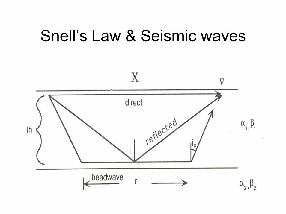
Snell’s Law & Seismic waves
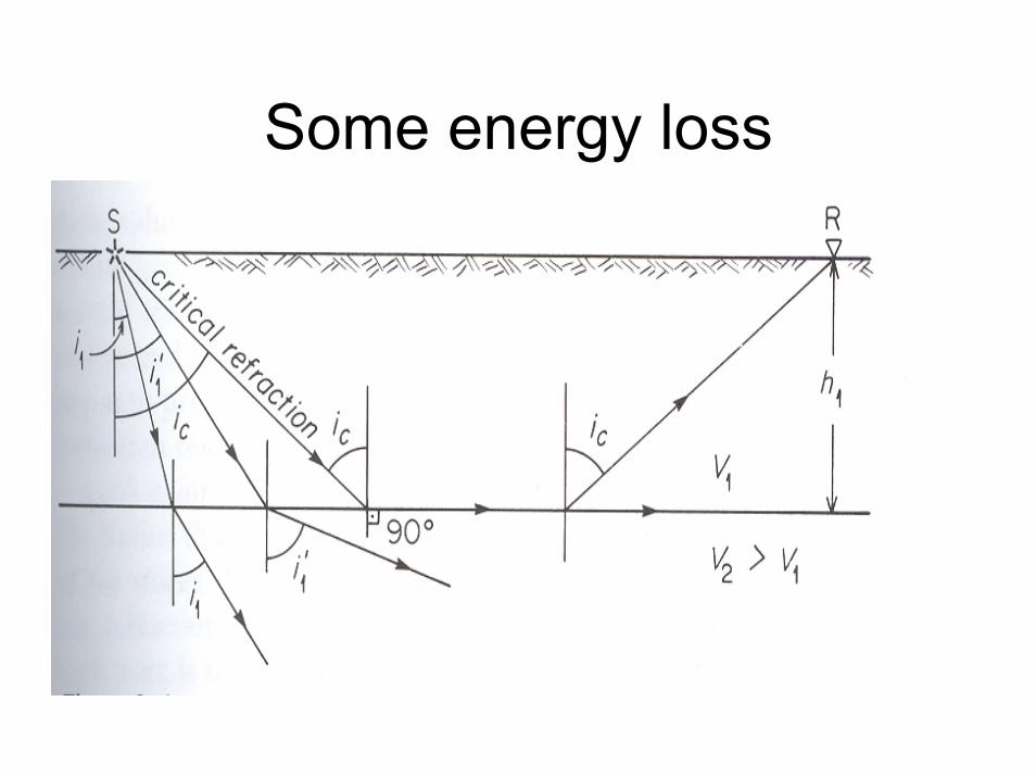
Some energy loss

Fundamental Observable
TRAVEL TIME
Our trusted friend !!

Do question 2 in the in-class exercise sheet
V2>V1

Time Relationships
1/VXTdir =
])/[cos(2 1VhTrefl θ=
12 /)cos(2)/( VhVXT crefr θ+=

In a graph
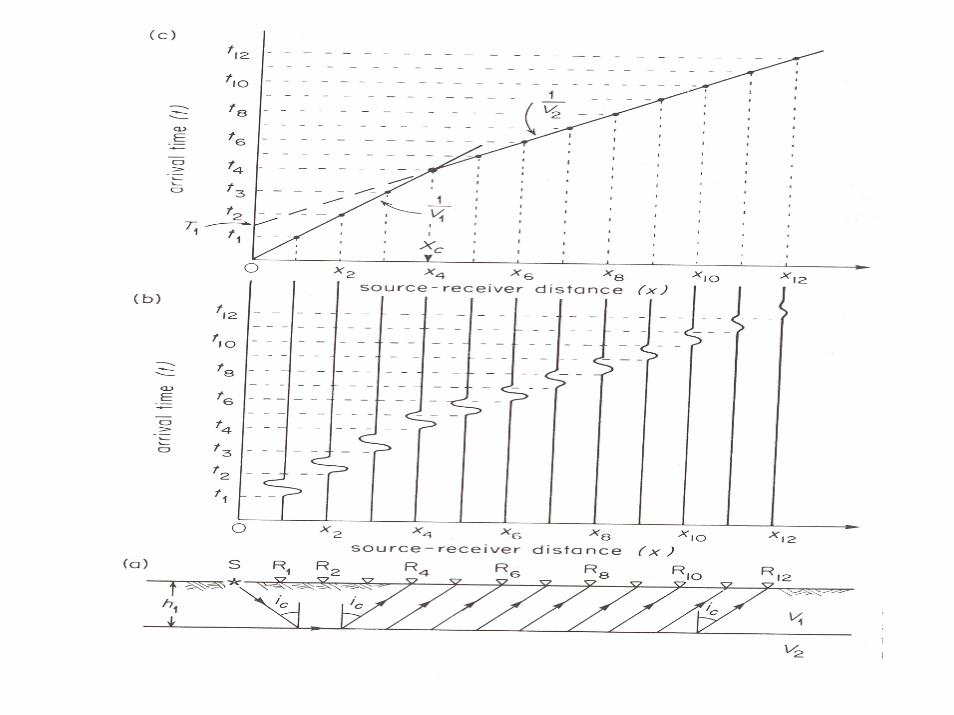
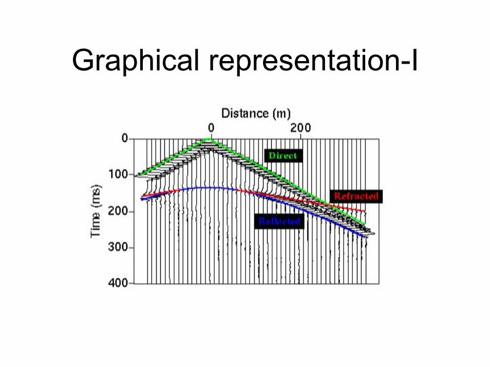
Graphical representation-I
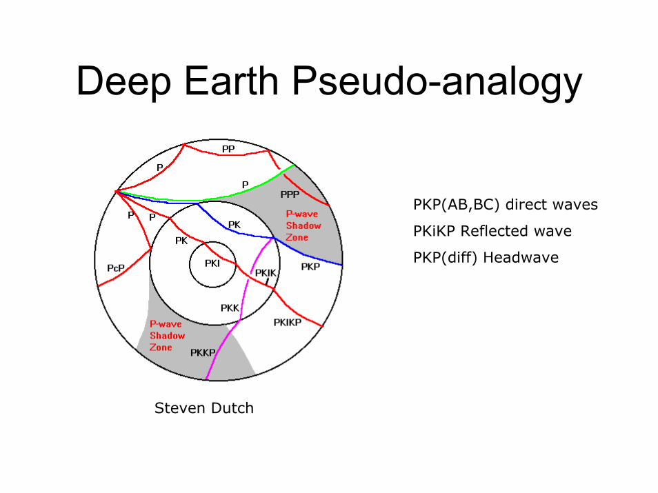
Deep Earth Pseudo-analogy
Steven Dutch
PKP(AB,BC) direct waves
PKiKP Reflected wave
PKP(diff) Headwave

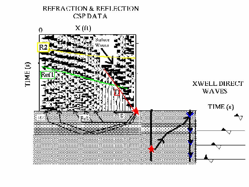
Complexities
*Travel times (Velocity perturbations) *Ray paths are affected by the subsurface structures
*Noise
ρµ)34( += KVp
ρµ
=sV

Enviroscan, inc.
Seismic MigrationMigration – Moving from one place to
another
What is Seismic Migration?“A data processing technique”
-Reflection seismic surveys-Accurate imaging of earth structures
Coming Attraction! “Proper Definition”

SM History1921 – First use, at the beginning of Seismic
Exploration (seismic exploration,p.6, fig-1.3b)
1920/40 – “Human computer” based methods1960/70 - Emergence of digital wave
equation technique
Oil industry – 1970/90 and present
23
Key Contributors
Principle ones: (Theoretical)F. Reiber, J.G. Hagedoorn, J.F. Claerbout
Others:C.H. Dix, M.M. Slotnick, H. Slattlegger, A.J. Berkhout, B Shneider, R. Stolt, Moore
Bednar J.B.
Seismic reflection survey
1) Source
2) Detectors
3) Data processing system

Source

Detectors (Geophones)

Data processing system
+ Seismologists
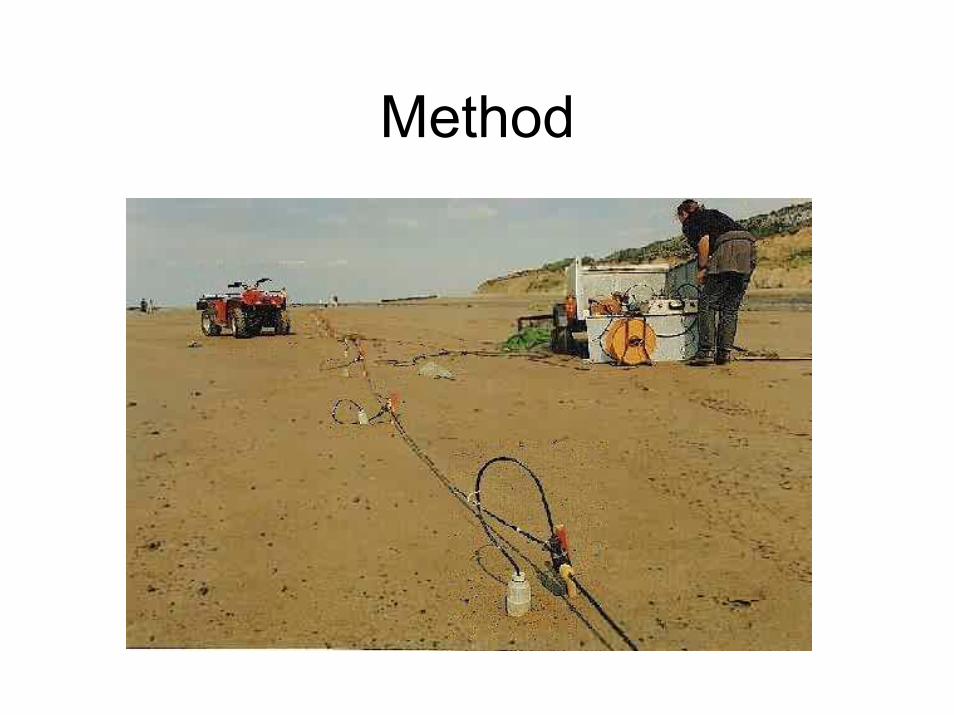
Method

Cross section
http://www.litho.ucalgary.ca/atlas/seismic.html
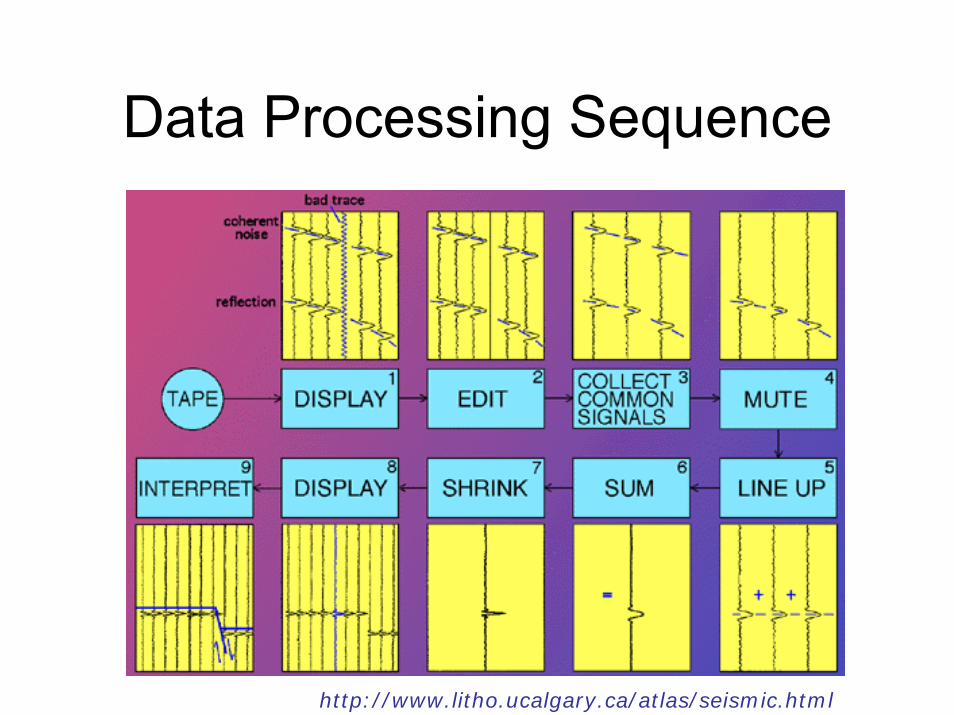
Data Processing Sequence
http://www.litho.ucalgary.ca/atlas/seismic.html
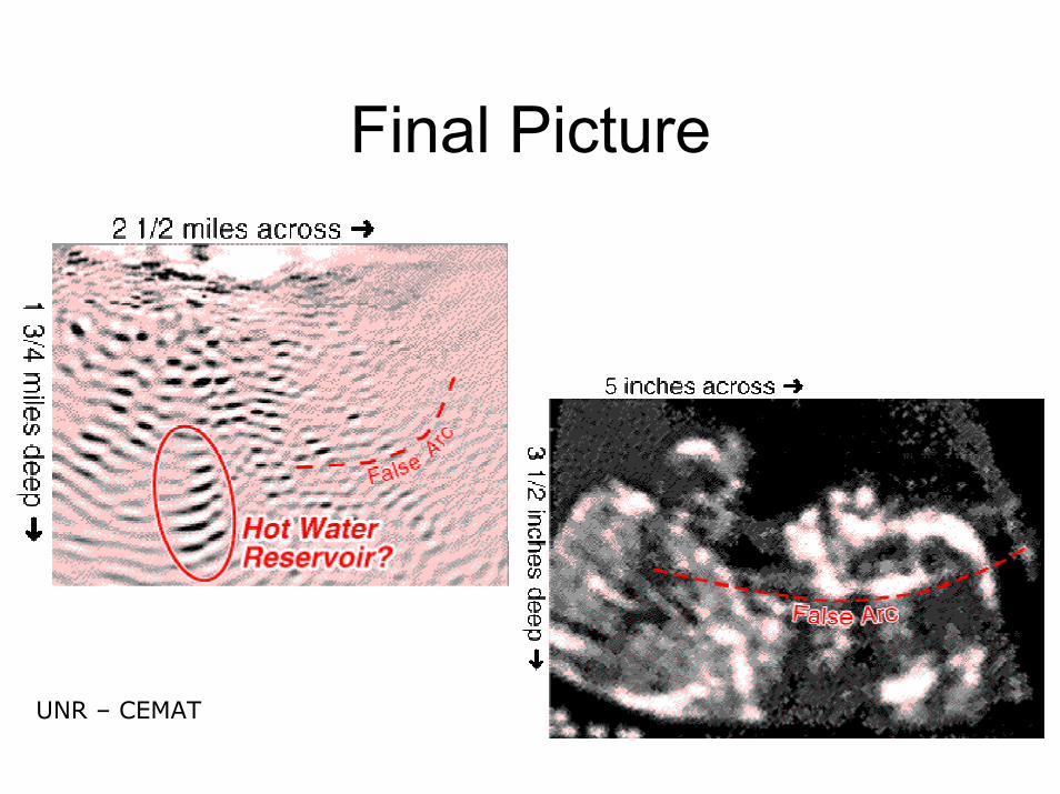
Final Picture
UNR – CEMAT

Got a problem?
Each CDP stacked trace in a seismic section is plotted to show reflections in positions that correspond to vertical travel paths
CDP – Common Depth Point
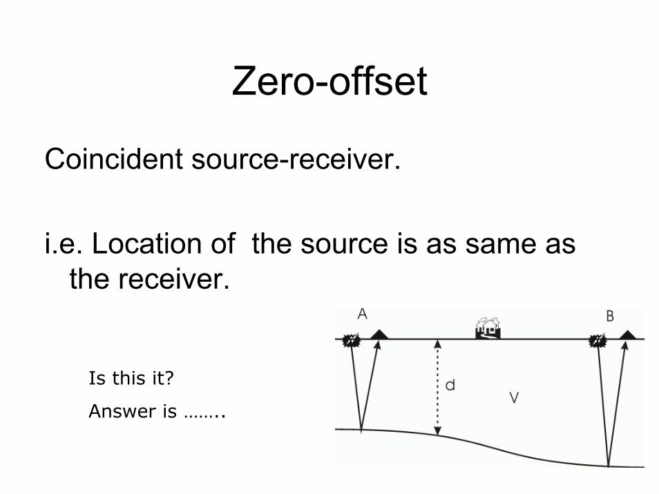
Zero-offset
Coincident source-receiver.
i.e. Location of the source is as same as the receiver.
Is this it?
Answer is ……..

Inclined flat reflector problem
Basic Exploration p.188
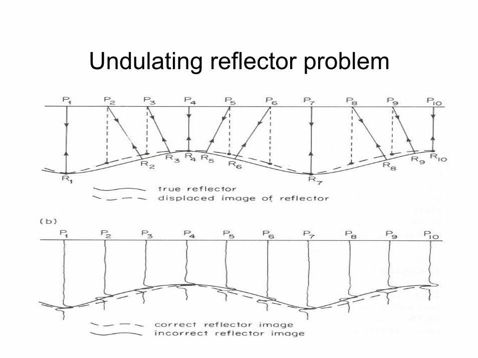
Undulating reflector problem

Cause of distortionPlotting depths calculated from arrival times
in incorrect positions
*Not from incorrect travel times
Seismic Migration
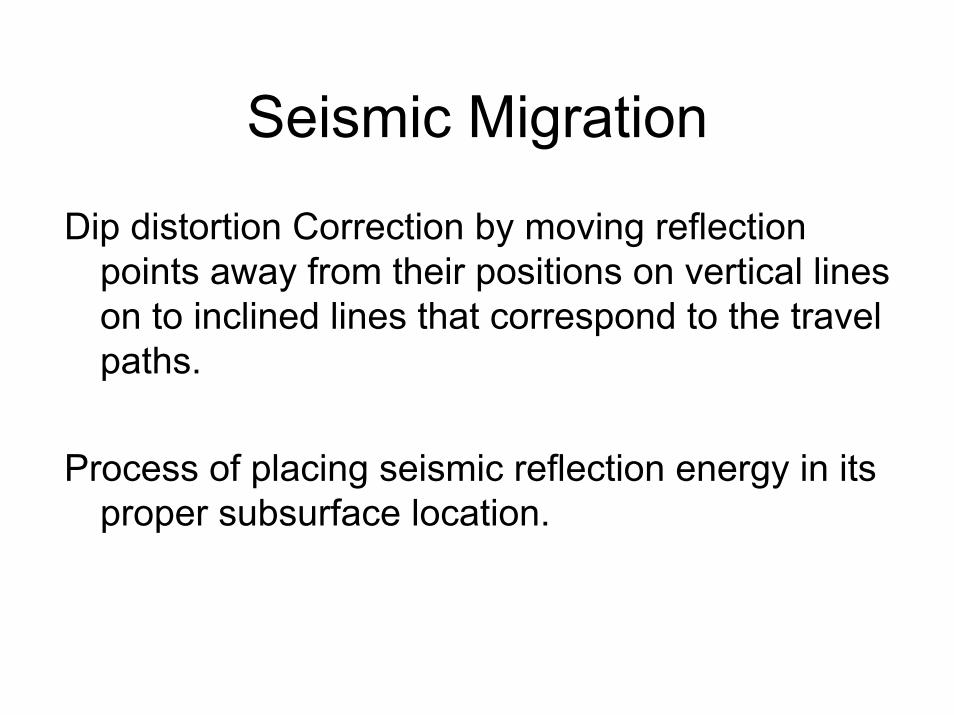
Dip distortion Correction by moving reflection points away from their positions on vertical lines on to inclined lines that correspond to the travel paths.
Process of placing seismic reflection energy in its proper subsurface location.
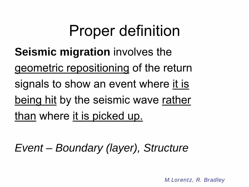
Proper definitionSeismic migration involves the geometric repositioning of the return signals to show an event where it is being hit by the seismic wave rather than where it is picked up.
Event – Boundary (layer), Structure
M.Lorentz, R. Bradley

39
BREAK
I am tired ! Lets have a 10 minute BREAK !!

Basic Idea
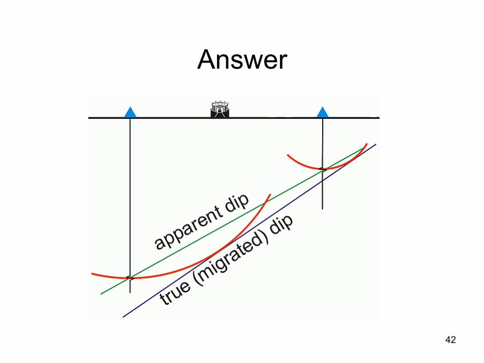
Question -3Do question 3 (a),(b) of in-class exercise
sheet.
42
Answer

Finding dip angle
44
Question -4
Do question 4 in your in-class work sheet.
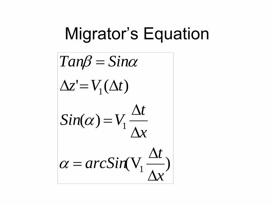
Migrator’s Equation
)V(
)(
)('
1
1
1
xtarcSin
xtVSin
tVzSinTan
∆∆
=
∆∆
=
∆=∆=
α
α
αβ

True Coordinates
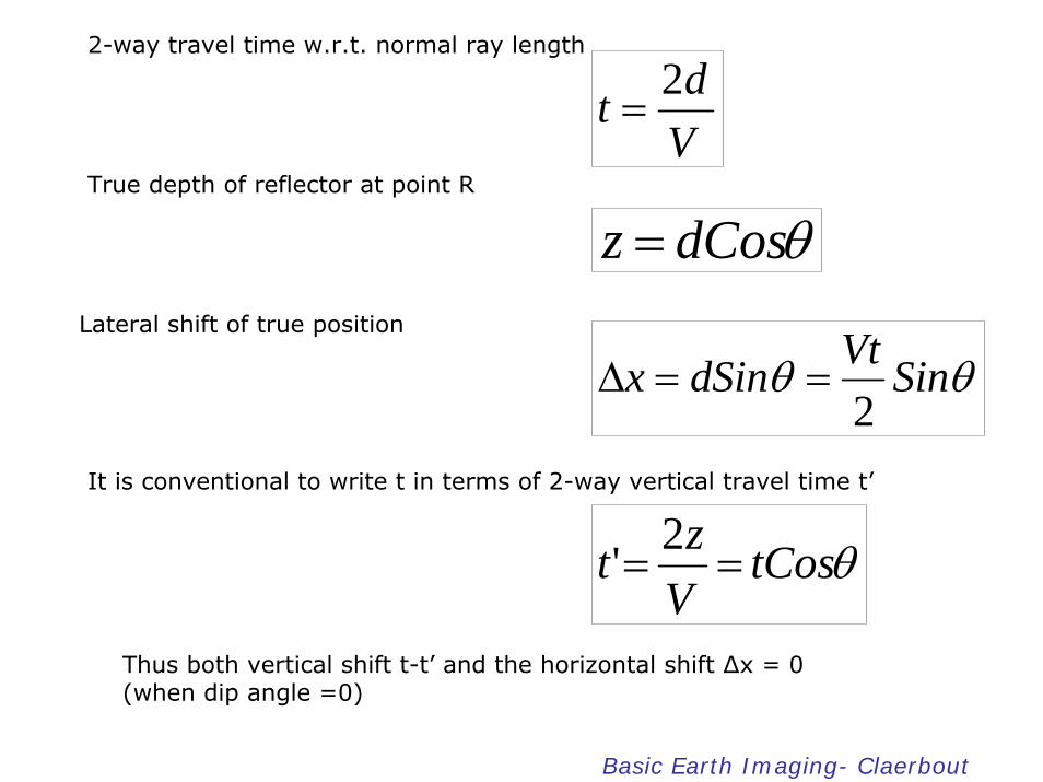
2-way travel time w.r.t. normal ray length
Vdt 2
=
True depth of reflector at point R
θdCosz =Lateral shift of true position
θθ SinVtdSinx2
==∆
It is conventional to write t in terms of 2-way vertical travel time t’
θtCosVzt ==
2'
Thus both vertical shift t-t’ and the horizontal shift ∆x = 0 (when dip angle =0)
Basic Earth Imaging- Claerbout

Hand Migration(HM)Before computerized migrationSeveral schemes
∆x & t’ require,t – readily measured v – from finite-offset θ - measurable as follows…..

ytp
∂∂
=0
Where; p0 - time dip of the event or simply dip of the event
y - The midpoint coordinate, the location of source-receiver pair
41'
4
2
22
2
0
pVtt
ptVx
VpSin
−=
=∆
=θTuchel’s Law;
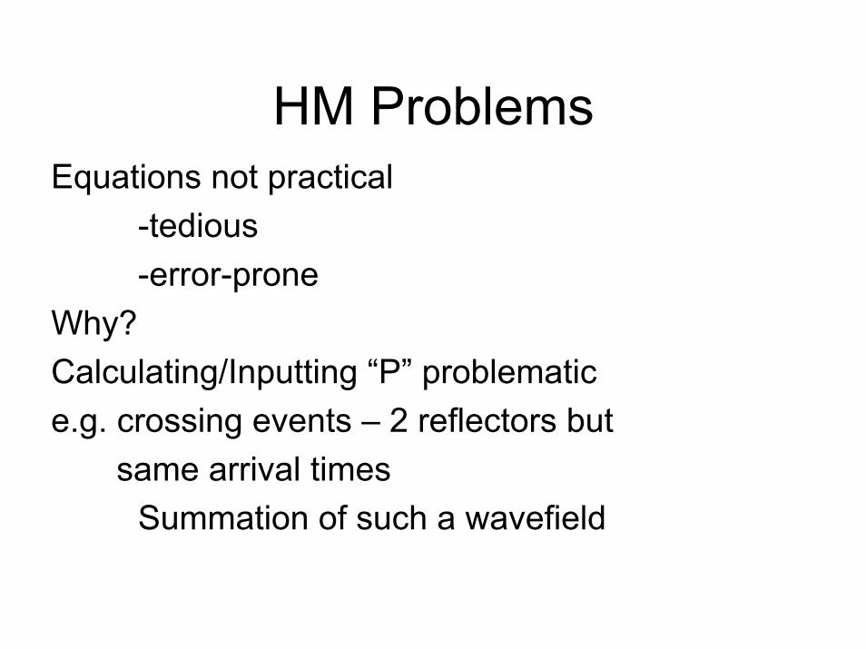
HM ProblemsEquations not practical
-tedious -error-prone
Why? Calculating/Inputting “P” problematice.g. crossing events – 2 reflectors but
same arrival timesSummation of such a wavefield

What are these?

Diffraction & Distortion

True Point

Purpose of Migration
1) Reposition reflections
2) Remove diffraction images
* General purpose migration
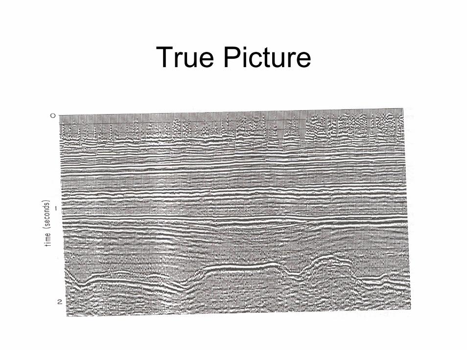
True Picture

Different Approaches
Time Reverse MigrationKirchhoff Migration
*In addition, there are many other approaches. (Exploration seismology p. 326-335)
Time Reverse Migration“Depropagate” seismic waves to its origin. i.e. reverse the path of seismic reflections
back to the geologic reflector by reversing time
Literature: Hermon(1978), Baysal et.al.(1983), Loewenthal & Mufti(1983), McMechan(1983), Whitemore(1983,1986), Mufti et.al.(1996), Zhu & Lines (1998)

Principle-IWe live in 4-D (space & time)
Any one of them can be reversed !Time, not physically!
why?
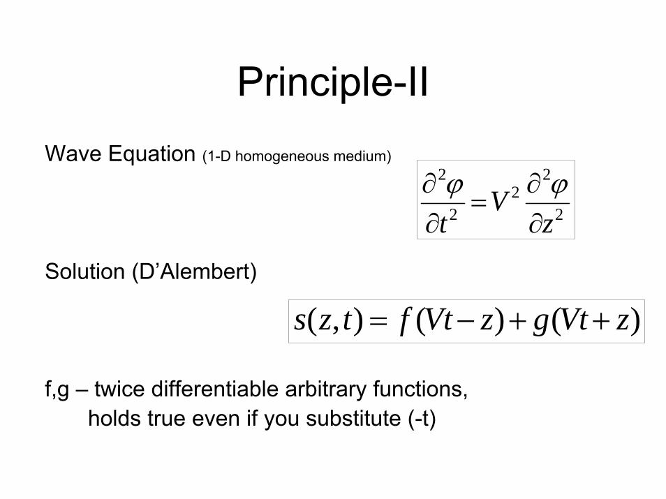
Principle-IIWave Equation (1-D homogeneous medium)
Solution (D’Alembert)
f,g – twice differentiable arbitrary functions, holds true even if you substitute (-t)
2
22
2
2
zV
t ∂∂
=∂∂ ϕϕ
)()(),( zVtgzVtftzs ++−=
Experiment, Hello olleH !• Time-Reversed Acoustics; November 1999; Scientific American
Magazine; by Fink; 7 Page(s) • In a room inside the Waves and Acoustics Laboratory in Paris is an
array of microphones and loudspeakers. If you stand in front of this array and speak into it, anything you say comes back at you, butplayed in reverse. Your "hello" echoes-almost instantaneously-as "olleh." At first this may seem as ordinary as playing a tape backward, but there is a twist: the sound is projected back exactly toward its source. Instead of spreading throughout the room fromthe loudspeakers, the sound of the "olleh" converges onto your mouth, almost as if time itself had been reversed. Indeed, the process is known as time-reversed acoustics, and the array in front of you is acting as a "time-reversal mirror."
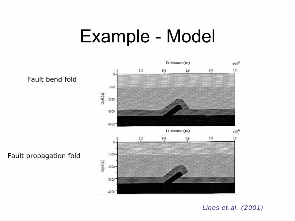
Example - Model
Fault bend fold
Fault propagation fold
Lines et.al. (2001)

Example - Interpretation
Zero-offset sectionMigrated section
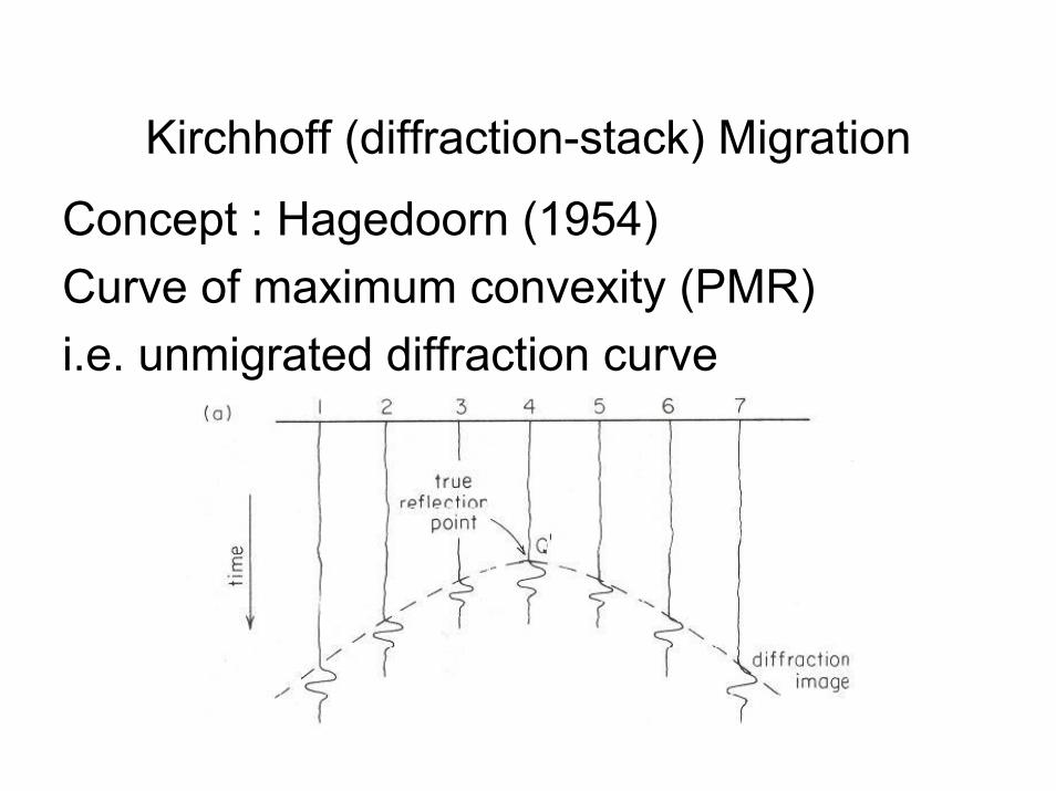
Kirchhoff (diffraction-stack) Migration
Concept : Hagedoorn (1954)Curve of maximum convexity (PMR)i.e. unmigrated diffraction curve

Kirchhoff Method#1 Calculate the diffraction curves for
each reflector point on the unmigratedsection
#2 Data on the unmigrated section lying along this curve summed up
#3 This gives the amplitude at the respective migrated point
If, Signal – approprate value Noise – (+) + (-) values (small sum)
Kirchhoff MethodEach element of an unmigrated reflection is treated as a portion of a diffraction.
i.e. Reflector – sequence of closely spaced diffracting points

Point Reflector
Diffraction migrates into a point
Diffraction curve of
an unmigrated
reflector element

Array Reflector

Linear Reflector

NoiseBurst of noise in an unmigratedsection
Migrates in to a wavefront
“A Smile”
NoteResults of wavefront smearing (previous
figures) are identical to Kirchhoff migration results (Sheriff, 1978).

More notes…Amplitudes are adjusted for obliquity and
divergence before summing
Introduce a wavelet-shaping factor to correct amplitudes
(Schneider, 1979), (Berryhill, 1979)
Near-field terms are neglected for collapsing diffraction curves as wave propagation in spherical coordinates

Aperture Definition ProblemAperture: Range of data included in the
migration of each point
How far down the diffraction curve the summation should extend?
General Rule:Aperture > 2x horizontal distance of width migration of the reflector having
steepest dips

Other Kirchhoff approaches
Kirchhoff integral:Find integral Solution to the wave equation (Schneider 1978)
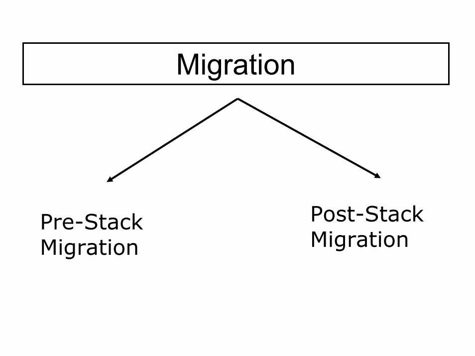
Migration
Pre-Stack Migration
Post-Stack Migration

Pre-stack Migration
Migrate data before stacking sequence occurs.
*Pre-stack depth migration (PDM)*Require more knowledge about subsurface
velocity structure*Better results

Applications & Problems
# Complex subsurface structure
# Complex subsurface Velocity Structure
# Modeling salt diapirs
# Expensive
# Time consuming

Pre-stack final picture
Post-stack MigrationSeismic data is migrated after stacking sequence occurs.
Basis: All data elements-Primary Reflections-Diffractions

Applications/Problems# Low dip non-interfering events
# Faster data processing
# Low cost
# Resolution < pre-stack migration
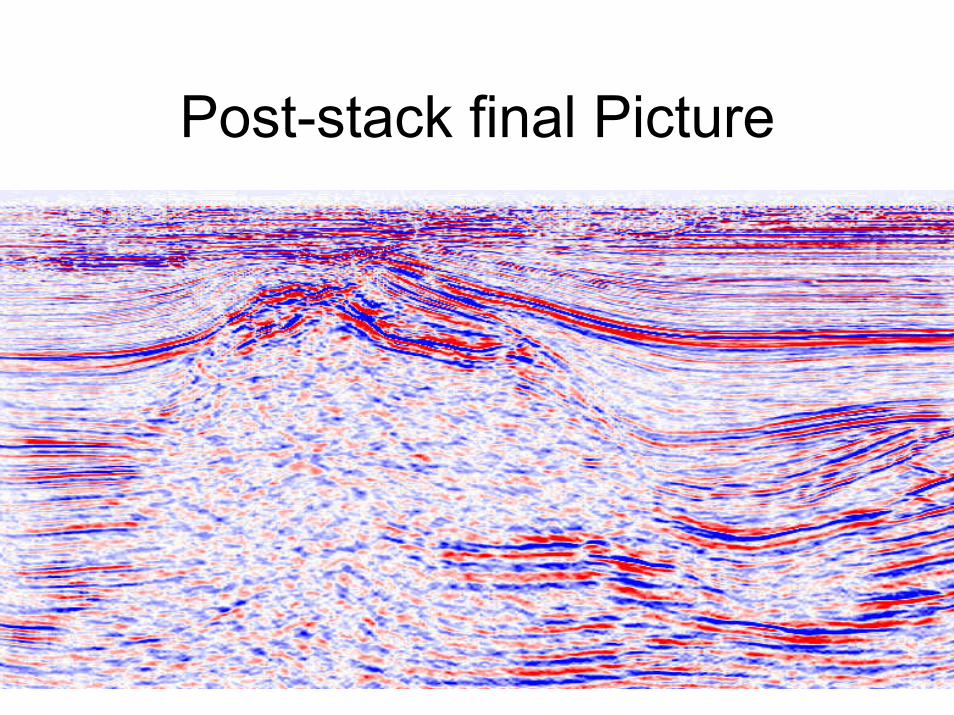
Post-stack final Picture
Main References:*Basic Exploration Seismology, Robinson & Coruh*Modern Global Seismology, Lay & Wallace*Exploration Seismology, Sheriff & Geldart*http://sepwww.stanford.edu/sep/prof/index.html* Lines et.al.(2001), Depth Imaging “if we could turn back
time”, CSEG Recorder *http://www.geol.lsu.edu/Faculty/Juan/ReflectSeismol97/rc
bradley/WWW/rcbradley1.html*Bednar.,J.B.(2005), A brief history of seismic migration,
SEG digital library, doi:10.1190/1.1926579*University Physics, Sanny & Moebs


