
R
SAFE
BOO
K 4
Safety related control systems for machineryPrinciples, standards and implementation

SAFEBOOK 4
Safety related control systems for machinery
1
ContentsChapter 1 Regulations .................................................................................... 2
EU Directives and Legislation, The Machinery Directive, The Use of WorkEquipment Directive, U.S. Regulations, Occupational Safety and HealthAdministration, Canadian Regulations
Chapter 2 Standards ..................................................................................... 18ISO (International Organisation for Standardisation), IEC (InternationalElectrotechnical Commission), EN Harmonised European Standards, U.S. Standards,OSHA Standards, ANSI Standards, Canadian Standards, Australian Standards
Chapter 3 Safety Strategy ............................................................................. 23Risk Assessment, Machine Limit Determination, Task and Hazard Identification,Risk Estimation and Risk Reduction, Inherently safe design, Protective systems andmeasures, Evaluation, Training, personal protective equipment, Standards
Chapter 4 Protective Measures & Complimentary Equipment .................. 36Preventing Access, Fixed Enclosing Guards, Detecting Access and Safety Productsand Systems
Chapter 5 Safety Distance Calculation ........................................................ 59Formulas, guidance and application of safety solutions utilising safety distancecalculations for safe control of potentially hazardous moving parts.
Chapter 6 Prevention of Unexpected Power-up ......................................... 63Lockout / Tagout, Safety Isolation Systems, Load Disconnects, Trapped KeySystems, Alternative Measures to Lockout
Chapter 7 Safety Related Control Systems & Functional Safety ............ 65Introduction, What is Functional Safety? IEC/EN 62061 and EN ISO 13849-1:2008,SIL and IEC/EN 62061, PL and EN ISO 13849-1:2008, Comparison of PL and SIL
Chapter 8 System design according to EN ISO 13849-1:2008 .................. 71Safety System Architectures (Structures), Mission Time, Mean Time to DangerousFailure (MTTFd), Diagnostic Coverage (DC), Common Cause Failure (CCF),Systematic Failure, Performance Level (PL), Subsystem Design and Combinations,Validation, Machine Commissioning, Fault Exclusion
Chapter 9 System Design According to IEC/EN 62061 .............................. 94Subsystem Design – IEC/EN 62061, Affect of the Proof Test Interval, Affect ofCommon Cause Failure Analysis, Transition methodology for Categories,Architectural Constraints, B10 and B10d, Common Cause Failure (CCF), DiagnosticCoverage (DC), Hardware Fault Tolerance, Management of Functional Safety,Probability of Dangerous Failure (PFHD), Proof Test Interval, Safe Failure Fraction(SFF), Systematic Failure
Chapter 10 Safety Related Control System, Structure Considerations ..... 106Overview, Categories of Control Systems, Undetected Faults, Component andSystem Ratings, Fault Considerations, Fault Exclusions, Stop Categories Accordingto IEC/EN 60204-1 and NFPA 79, U.S. Safety Control System Requirements, RobotStandards: U.S. and Canada
Chapter 11 Application example using SISTEMA ....................................... 130Application example of how you could use SISTEMA Performance Level Calculatortool with Rockwell Automation SISTEMA product library

2
SAFEBOOK 4
Safety related control systems for machinery
EU Directives and Legislation
The purpose of this section is to act as a guide for anyone concerned with machinesafety especially guarding and protective systems in the European Union. It isintended for designers and users of industrial equipment.
In order to promote the concept of an open market within the European EconomicArea (EEA) (which comprises all EU Member States plus three other countries) allmember states are obliged to enact legislation that defines essential safetyrequirements for machinery and its use.
Machinery that does not meet these requirements cannot be supplied into or withinEEA countries.
There are several European Directives that can apply to the safety of industrialmachinery and equipment but the two that are of the most direct relevance are:
1 The Machinery Directive
2 The Use of Work Equipment by Workers at Work Directive
These two Directives are directly related as the Essential Health and SafetyRequirements (EHSRs) from the Machinery Directive can be used to confirm thesafety of equipment in the Use of Work Equipment Directive.
This section deals with aspects of both directives and it is strongly recommendedthat anyone concerned with the design, supply, purchase or use of industrialequipment within or into the EEA and also certain other European countries shouldfamiliarize themselves with their requirements. Most suppliers and users ofmachinery will simply not be allowed to supply or operate machinery in thesecountries unless they conform to these directives.
There are other European Directives that may have relevance to machinery. Most ofthem are fairly specialized in their application and are therefore left outside thescope of this section but it is important to note that, where relevant, theirrequirements must also be met. Examples are: The EMC Directive 2004/108/ECand the ATEX Directive 94/9/EC.

SAFEBOOK 4
Regulations
3
The Machinery Directive
The Machinery Directive covers the supply of new machinery and other equipmentincluding safety components. It is an offense to supply machinery within the EUunless the provisions and requirements of the Directive are met.
The broadest definition of “machinery” given within the Directive is a follows: anassembly, fitted with or intended to be fitted with a drive system other than directlyapplied human or animal effort, consisting of linked parts or components, at leastone of which moves, and which are joined together for a specific application
The current Machinery Directive(2006/42/EC) replaced the former version(98/37/EC) at the end of 2009. It clarifiesand amends but does not introduce anyradical changes to its Essential Health andSafety Requirements (EHSRs). It doesintroduce some changes to take accountof changes in technology and methods. Itextends its scope to cover some extratypes of equipment (e.g. construction sitehoists). There is now an explicit
requirement for a risk assessment for the determination of which EHSRs areapplicable and there are changes made to the conformity assessment proceduresfor Annex IV equipment.
The key provisions of the original Directive (98/37/EC) came into force formachinery on January 1, 1995 and for Safety Components on January 1, 1997.
The provisions of the current Directive (2006/42/EC) became applicable onDecember 29, 2009. It is the responsibility of the manufacturer or his authorizedrepresentative to ensure that equipment supplied is in conformity with the Directive.This includes:
• Ensuring that the applicable EHSRs contained in Annex I of the Directiveare fulfilled
• A technical file is prepared • Appropriate conformity assessment is carried out • An “EC Declaration of Conformity” is given • CE Marking is affixed where applicable • Instructions for safe use are provided
CE marking affixed to machine

4
SAFEBOOK 4
Safety related control systems for machinery
Essential Health & Safety Requirements
Annex 1 of the Directive gives a list ofEssential Health and Safety Requirements(referred to as EHSRs) to whichmachinery must comply where relevant.The purpose of this list is to ensure thatthe machinery is safe and is designed andconstructed so that it can be used,adjusted and maintained throughout allphases of its life without putting persons atrisk. The following text provides a quickoverview of some typical requirements but
it is important to consider all of the EHSRs given in Annex 1
A risk assessment must be carried out to determine which EHSRs are applicable tothe equipment under consideration.
The EHSRs in Annex 1 provides a hierarchy of measures for eliminating the risk:
(1) Inherently Safe Design. Where possible the design itself will prevent any hazards.
Where this is not possible (2) Additional Protection Devices, e.g., Guards withinterlocked access points, non-material barriers such as light curtains, sensing matsetc. should be used.
Any residual risk which cannot be dealt with by the above methods must becontained by (3) Personal Protective Equipment and/or Training. The machinesupplier must specify what is appropriate.
Suitable materials should be used for construction and operation. Adequate lightingand handling facilities should be provided. Controls and control systems must besafe and reliable. Machines must not be capable of starting up unexpectedly andshould have one or more emergency stop devices fitted. Consideration must begiven to complex installations where processes upstream or downstream can affectthe safety of a machine. Failure of a power supply or control circuit must not lead toa dangerous situation. Machines must be stable and capable of withstandingforeseeable stresses. They must have no exposed edges or surfaces likely tocause injury.
Machine must meet EHSRs

SAFEBOOK 4
Regulations
5
Guards or protection devices must be used to protect risks such as moving parts.These must be of robust construction and difficult to bypass. Fixed guards must bemounted by methods that can only be removed with tools. Movable guards should beinterlocked. Adjustable guards should be readily adjustable without the use of tools.
Electrical and other energy supply hazards must be prevented. There must beminimal risk of injury from temperature, explosion, noise, vibration, dust, gases orradiation. There must be proper provisions for maintenance and servicing. Sufficientindication and warning devices must be provided. Machinery shall be provided withinstructions for safe installation, use, adjustment etc.
Conformity Assessment
The designer or other responsible body must be able to show evidence that provesconformity with the EHSRs. This file should include all relevant information such astest results, drawings, specifications, etc.
A harmonized European (EN) Standardthat is listed in the Official Journal of theEuropean Union (OJ) under the MachineryDirective, and whose date of cessation ofpresumption of conformity has notexpired, confers a presumption ofconformity with certain of the EHSR’s.(Many recent standards listed in the OJinclude a cross-reference identifying theEHSR’s that are covered by the standard).
Therefore, where equipment complies withsuch current harmonized European standards, the task of demonstrating conformitywith the EHSR’s is greatly simplified, and the manufacturer also benefits from theincreased legal certainty. These standards are not legally required, however, theiruse is strongly recommended since proving conformity by alternative methods canbe an extremely complex issue. These standards support the Machinery Directiveand are produced by CEN (the European Committee for Standardization) incooperation with ISO, and CENELEC (the European Committee for ElectrotechnicalStandardization) in cooperation with IEC.
A thorough, documented risk assessment must be conducted to ensure that allpotential machine hazards are addressed. Similarly, it is the responsibility of themachine manufacturer to ensure that all EHSR’s are satisfied, even those that arenot addressed by harmonized EN Standards.
TEST RESULTS------------------------------------------------------------
STANDARDS
Machine must meet EHSRs

6
SAFEBOOK 4
Safety related control systems for machinery
Technical File
The manufacturer or his authorized representative must prepare a Technical File toprovide evidence of conformity with the EHSRs. This file should include all relevantinformation such as test results, drawings, specifications, etc.
It is not essential that all the information is permanently available as hard copy but itmust be possible to make the entire Technical File available for inspection onrequest from a competent authority (a body appointed by an EU country to monitorthe conformity of machinery).
At the minimum, the following documentation must be included in a Technical File:
1. Overall drawings of the equipment including control circuit drawings.
2. Detailed drawings, calculation notes, etc. required for checking the conformity ofthe machinery with the EHSRs.
3. Risk assessment documentation, including a list of the essential health andsafety requirements which apply to the machinery and a description of theprotective measures implemented
4 A list of the standards and other technical specifications used, indicating theessential health and safety requirements covered.
5 A description of methods adopted to eliminate hazards presented by themachinery.
6 If relevant, any technical reports or certificates obtained from a test facility orother body.
7 If conformity is declared with a Harmonized European Standard, any technicalreport giving test results for it.
8 A copy of the instructions for the machinery.
9 Where appropriate, the declaration of incorporation for included partly completedmachinery and the relevant assembly instructions for such machinery.
10 Where appropriate, copies of the EC declaration of conformity of machinery orother products incorporated into the machinery.
11 A copy of the EC declaration of conformity

SAFEBOOK 4
Regulations
7
For series manufacture, details of internal measures (quality systems, for example)to ensure that all machinery produced remains in conformity:
• The manufacturer must carry out necessary research or tests oncomponents, fittings or the completed machinery to determine whether by itsdesign and construction it is capable of being erected and put into servicesafely.
• The technical file need not exist as a permanent single file, but it must bepossible to assemble it to make it available in a reasonable time. It must beavailable for ten years following production of the last unit.
The technical file does not need to include detailed plans or any other specificinformation regarding sub-assemblies used for the manufacture of the machinery,unless they are essential to verify conformity with the EHSRs.
Conformity Assessment for Annex IV Machines
Certain types of equipment are subject tospecial measures. This equipment is listedin Annex IV of the Directive and includesdangerous machines such as somewoodworking machines, presses, injectionmoulding machines, undergroundequipment, vehicle servicing lifts, etc.
Annex IV also includes certain safetycomponents such as Protective devicesdesigned to detect the presence ofpersons (e.g. light curtains) and logic unitsfor ensuring safety functions.
For Annex IV machines that are not in full conformity with the relevant HarmonizedEuropean Standards the manufacturer or his authorized representative must applyone of the following procedures:
1. EC Type Examination. A Technical File must be prepared and an example ofthe machine must submitted to a notified body (test house) for EC typeexamination. If it passes, the machine will be given an EC type examinationcertificate. The validity of the certificate must be reviewed every five years withthe Notified Body.
TEST RESULTS--------
----- ----------------STANDA
RDS
Technical
File
Conformity assessments

8
SAFEBOOK 4
Safety related control systems for machinery
2. Full Quality Assurance. A Technical File must be prepared and the manufacturermust operate an approved quality system for design, manufacture, finalinspection and testing. The quality system must ensure conformity of themachinery with the provisions of this Directive. The quality system must beperiodically audited by a Notified Body.
For machines that are not included inAnnex IV or machines that are included inAnnex IV but are in full conformity with therelevant Harmonized EuropeanStandards, the manufacturer or hisauthorized representative also has theoption prepare the Technical and selfassess and declare the conformity of theequipment. There must be internal checksto ensure that the manufacturedequipment remains in conformity.
Notified Bodies
A network of notified bodies that communicate with each other and work to commoncriteria exists throughout the EU. Notified Bodies are appointed by governments (not byindustry) and details of organizations with notified body status can be obtained from:
http://ec.europa.eu/enterprise/sectors/mechanical/machinery/index_ en.htm
EC Declaration of Conformity Procedure
The CE Marking must be applied to all machines supplied. Themachines should also be supplied with an EC Declaration of Conformity.
The CE Mark indicates that the machine conforms to all applicable EuropeanDirectives and that the appropriate conformity assessment procedures have beencompleted. It is an offense to apply the CE Mark for the Machinery Directive unlessthe machine satisfies the relevant EHSRs.
Notified body examinations

SAFEBOOK 4
Regulations
9
The EC Declaration of Conformity must contain the following information:
• Business name and full address of the manufacturer and, where appropriate,the authorized representative
• Name and address of the person authorized to compile the technical file,who must be established in the Community (in the case of a manufactureroutside the EU this may be the “Authorized Representative”) ;
• Description and identification of the machinery, including genericdenomination, function, model, type, serial number and commercial name;
• A sentence expressly declaring that the machinery fulfills all the relevantprovisions of this Directive and where appropriate, a similar sentencedeclaring the conformity with other Directives and/or relevant provisions withwhich the machinery complies;
• Where appropriate, a reference to the harmonized standards used; • Where appropriate, the reference to other technical standards and
specifications used; • (For an Annex IV machines) where appropriate, the name, address and
identification number of the notified body which carried out the EC type-examination referred to in Annex IX and the number of the EC type-examination certificate;
• (For an Annex IV machines) where appropriate, the name, address andidentification number of the notified body which approved the full qualityassurance system referred to in Annex X;
• The place and date of the declaration; • The identity and signature of the person empowered to draw up the
declaration on behalf of the manufacturer or the authorized representative.
EC Declaration of Incorporation for Partly Completed Machinery
Where the equipment is supplied for assembly with other items to form a completemachine at a later date, a DECLARATION OF INCORPORATION should be issuedwith it. The CE mark should not be applied. The declaration should state that theequipment must not be put into service until the machine into which it has beenincorporated has been declared in conformity. A Technical File must be preparedand the partly completed machinery must be supplied with information containing adescription of the conditions which must be met with a view to correct incorporationin the final machinery, so as not to compromise safety.
This option is not available for equipment which can function independently or whichmodifies the function of a machine.

10
SAFEBOOK 4
Safety related control systems for machinery
The Declaration of Incorporation must contain the following information:
• Business name and full address of the manufacturer of the partly completedmachinery and, where appropriate, the authorized representative;
• Name and address of the person authorized to compile the relevant technicaldocumentation, who must be established in the Community (in the case of amanufacturer outside the EU this may be the “Authorized Representative”);
• Description and identification of the partly completed machinery includinggeneric denomination, function, model, type, serial number and commercialname;
• A sentence declaring which essential requirements of this Directive areapplied and fulfilled and that the relevant technical documentation iscompiled in accordance with part B of Annex VII, and, where appropriate, asentence declaring the conformity of the partly completed machinery withother relevant Directives;
• An undertaking to transmit, in response to a reasoned request by thenational authorities, relevant information on the partly completed machinery.This shall include the method of transmission and shall be without prejudiceto the intellectual property rights of the manufacturer of the partly completedmachinery;
• A statement that the partly completed machinery must not be put into serviceuntil the final machinery into which it is to be incorporated has been declaredin conformity with the provisions of this Directive, where appropriate;
• The place and date of the declaration; • The identity and signature of the person empowered to draw up the
declaration on behalf of the manufacturer or the authorized representative.
Machinery Supplied from Outside the EU - AuthorizedRepresentatives
If a manufacturer based outside the EU (or EEA) exports machinery into the EUthey will need to appoint an Authorized Representative.
An Authorized Representative means any natural or legal person established in theEuropean Community who has received a written mandate from the manufacturer toperform on his behalf all or part of the obligations and formalities connected with theMachinery Directive.

SAFEBOOK 4
Regulations
11
The EU Use of Work Equipment Directive (U.W.E. Directive)
Whereas the Machinery Directive is aimed at suppliers, this Directive (89/655/EECas amended by 95/63/EC, 2001/45/EC and 2007/30/EC) is aimed at users ofmachinery. It covers all industrial sectors and it places general duties on employerstogether with minimum requirements for the safety of work equipment. All EUcountries are enacting their own forms of legislation to implement this Directive.
All machinery must satisfy the Essential Health and Safety Requirements
Most machines & safetycomponents (other thanthose listed in Annex IV)
Machines & safetycomponents listed in
Annex IV
Must conformwith relevantHarmonisedEuropeanstandards
Must conformdirectly with the
EHSRs
If it DOESCONFORM with
relevantHarmonisedEuropeanstandards
If it DOES NOTCONFORMwith relevantHarmonisedEuropeanstandards
OR
OR OR
Send theTECHNICALFILE to an
approved bodywhich will
acknowledge itsRECEIPT
Send theTECHNICAL FILE
to an approvedbody which willexamine it and
issue aCERTIFICATE OF
ADEQUACY forthe file
Send equipment toan approved body
for EC TYPEEXAMINATION
You must be ableto assemble the
TECHNICALFILE on request
It MUST besubmitted to an
Approved Body forEC Type
Examination
FOR MACHINERY—You must issue a Declaration of Conformity and affix theCE mark or issue a Declaration of Incorporation.
FOR SAFETY COMPONENTS—You must issue a Declaration of Conformity.
Overview proceedure for the Machinery Directive
12
SAFEBOOK 4
Safety related control systems for machinery
For example it is implementation in the UK under the name of The Provision andUse of Work Equipment Regulations (often abbreviated to P.U.W.E.R.). The form ofimplementation may vary between countries but the effect of the Directive isretained.
The articles of the Directive give details of which types of equipment and workplacesare covered by the Directive.
They also place general duties on employers such as instituting safe systems ofworking and providing suitable and safe equipment that must be properlymaintained. Machine operators must be given proper information and training for thesafe use of the machine.
New machinery (and second hand machinery from outside the EU) provided afterJanuary 1, 1993 should satisfy any relevant product directives, e.g., The MachineryDirective (subject to transitional arrangements). Second hand equipment from withinthe EU provided for the first time in the workplace must immediately provideminimum requirements given in an annex of the U.W.E. Directive.
Note: Existing or second-hand machinery which is significantly overhauled ormodified will be classified as new equipment, so the work carried out on it mustensure compliance with the Machinery Directive (even if it is for a company's ownuse).
Suitability of work equipment is an important requirement of the directive and ithighlights the employer’s responsibility to carry out a proper process of riskassessment.
It is a requirement that machinery must be properly maintained. This will normallymean that there must be a routine and planned preventive maintenance schedule. Itis recommended that a log is compiled and kept up to date. This is especiallyimportant in cases where the maintenance and inspection of equipment contributesto the continuing safety integrity of a protective device or system.
The Annex of the U.W.E. Directive gives general minimum requirements applicableto work equipment.
If the equipment conforms to relevant product directives, e.g., The MachineryDirective, they will automatically comply with the corresponding machine designrequirements given in the minimum requirements of the Annex.
Member states are allowed to issue legislation regarding the use of work equipmentthat goes beyond the minimum requirements of the U.W.E. Directive.

SAFEBOOK 4
Regulations
13
Detailed information on the Use of Work Equipment Directive can be found at theofficial EU website:
http://europa.eu/legislation_summaries/employment_and_social_policy/health_hygiene_safety_at_work/c11116_en.htm
U.S. Regulations
This section introduces some of the industrial machine guarding safety regulationsin the U.S. This is only a starting point; readers must further investigate therequirements for their specific applications and take measures to ensure that theirdesigns, uses and maintenance procedures and practices meet their own needs aswell as national and local codes and regulations.
There are many organizations that promote industrial safety in the United States.These include:
1. Corporations, which use established requirements as well as establish their owninternal requirements;
2. The Occupational Safety and Health Administration (OSHA);
3. Industrial organizations like the National Fire Protection Association (NFPA), theRobotics Industries Association (RIA), and the Association of ManufacturingTechnology (AMT); and the suppliers of safety products and solutions such asRockwell Automation.
Occupational Safety and Health Administration
In the United States, one of the main drivers of industrial safety is the OccupationalSafety and Health Administration (OSHA). OSHA was established in 1970 by an Actof the U.S. Congress. The purpose of this act is to provide safe and healthfulworking conditions and to preserve human resources. The act authorizes theSecretary of Labor to set mandatory occupational safety and health standardsapplicable to businesses affecting interstate commerce. This Act shall apply withrespect to employment performed in a workplace in a State, the District of Columbia,the Commonwealth of Puerto Rico, the Virgin Islands, American Samoa, Guam, theTrust Territory of the Pacific Islands, Wake Island, Outer Continental Shelf Landsdefined in the Outer Continental Shelf Lands Act, Johnston Island, and the CanalZone.
Article 5 of the Act sets the basic requirements. Each employer shall furnish to eachof his employees employment and a place of employment which are free from

14
SAFEBOOK 4
Safety related control systems for machinery
recognized hazards that are causing or are likely to cause death or serious physicalharm to his employees; and shall comply with occupational safety and healthstandards promulgated under this Act.
Article 5 also states that each employee shall comply with occupational safety andhealth standards and all rules, regulations, and orders issued pursuant to this Actwhich are applicable to his own actions and conduct.
The OSHA Act places the responsibility on both the employer and the employee.This is quite divergent from Machinery Directive, which requires suppliers to placemachines on the market that are free from hazards. In the U.S., a supplier can sell amachine without any safeguarding. The user must add the safeguarding to make themachine safe. Although this was a common practice when the Act was approved,the trend is for suppliers to provide machines with the safeguarding, as designingsafety into a machine is far more cost effective than adding the safeguarding afterthe machine is designed and built. Standards are now attempting to get the supplierand user to communicate requirements for safeguarding so that machines are madenot only safe but more productive.
The Secretary of Labor has the authority to promulgate as an occupational safety orhealth standard any national consensus standard, and any established Federalstandard, unless the promulgation of such a standard would not result in improvedsafety or health for specifically designated employees.
OSHA accomplishes this task by publishing regulations in Title 29 of the Code ofFederal Regulation (29 CFR). Standards pertaining to industrial machinery arepublished by OSHA in Part 1910 of 29 CFR. They are freely available on the OSAHwebsite at www.osha.gov. Unlike most standards, which are voluntary, the OSHAstandards are laws.
Some of the important parts as they pertain to machine safety are as follows:
A - GeneralB - Adoption and Extension of Established Federal StandardsC - General Safety and Health ProvisionsH - Hazardous MaterialsI - Personal Protective EquipmentJ - General Environmental Controls - includes Lockout/TagoutO - Machinery and Machine GuardingR - Special IndustriesS - Electrical

SAFEBOOK 4
Regulations
15
Some OSHA standards reference voluntary standards. The legal effect ofincorporation by reference is that the material is treated as if it were published infull in the Federal Register. When a national consensus standard is incorporatedby reference in one of the subparts, that standard is considered the law. Forexample, NFPA 70, a voluntary standard known as the US National ElectricCode, is referenced in Subpart S. This makes the requirements in the NFPA70standard mandatory.
The 29 CFR 1910.147, in Subpart J, covers the control of hazardous energy. Thisis commonly known as the Lockout/Tagout standard. The equivalent voluntarystandard is ANSI Z244.1. Essentially, this standard requires power to the machineto be locked out when undergoing service or maintenance. The purpose is toprevent the unexpected energization or startup of the machine which would resultin injury to employees.
Employers must establish a program and utilize procedures for affixing appropriatelockout devices or tagout devices to energy isolating devices, and to otherwisedisable machines or equipment to prevent unexpected energization, start up orrelease of stored energy in order to prevent injury to employees.
Minor tool changes and adjustments, and other minor servicing activities, which takeplace during normal production operations, are not covered by this standard if theyare routine, repetitive, and integral to the use of the equipment for production,provided that the work is performed using alternative measures which provideeffective protection. Alternative measures are safeguarding devices like lightcurtains, safety mats, gate interlocks and other similar devices connected to a safetysystem. The challenge to the machine designer and user is to determine what is“minor” and what is “routine, repetitive and integral.”
Subpart O covers “Machinery and Machine Guarding.” This subpart lists the generalrequirements for all machines as well as requirements for some specific machines.When OSHA was formed in 1970, it adopted many existing ANSI standards. Forexample B11.1 for mechanical power presses was adopted as 1910.217.
The 1910.212 is the general OSHA standard for machines. It states that one ormore methods of machine guarding shall be provided to protect the operator andother employees in the machine area from hazards such as those created by thepoint of operation, ingoing nip points, rotating parts, flying chips and sparks. Guardsshall be affixed to the machine where possible and secured elsewhere if for anyreason attachment to the machine is not possible. The guard shall be such that itdoes not offer an accident hazard in itself.

16
SAFEBOOK 4
Safety related control systems for machinery
The “point of operation” is the area on a machine where work is actually performedupon the material being processed. The point of operation of a machine, whoseoperation exposes an employee to injury, shall be guarded. The guarding device shallbe in conformity with any appropriate standards or, in the absence of applicablespecific standards, shall be so designed and constructed as to prevent the operatorfrom having any part of his body in the danger zone during the operating cycle.
Subpart S (1910.399) states the OSHA electrical requirements. An installation orequipment is acceptable to the Assistant Secretary of Labor, and approved withinthe meaning of this Subpart S if it is accepted, certified, listed, labeled, or otherwisedetermined to be safe by a nationally recognized testing laboratory (NRTL).
What is Equipment? A general term including material, fittings, devices, appliances,fixtures, apparatus, and the like, used as a part of, or in connection with, anelectrical installation.
What is “Listed”? Equipment is “listed” if it is of a kind mentioned in a list which, (a) ispublished by a nationally recognized laboratory which makes periodic inspection of theproduction of such equipment, and (b) states such equipment meets nationallyrecognized standards or has been tested and found safe for use in a specified manner.
As of August 2009, the following companies are recognized by OSHA as NRTLs:
• Canadian Standards Association (CSA) • Communication Certification Laboratory, Inc. (CCL) • Curtis-Straus LLC (CSL) • FM Approvals LLC (FM) • Intertek Testing Services NA, Inc. (ITSNA) • MET Laboratories, Inc. (MET) • NSF International (NSF) • National Technical Systems, Inc. (NTS) • SGS U.S. Testing Company, Inc. (SGSUS) • Southwest Research Institute (SWRI) • TUV America, Inc. (TUVAM) • TUV Product Services GmbH (TUVPSG) • TUV Rheinland of North America, Inc. (TUV) • Underwriters Laboratories Inc. (UL) • Wyle Laboratories, Inc. (WL)
Some states have adopted their own local OSHAs. Twenty-four states, Puerto Ricoand the Virgin Islands have OSHA-approved State Plans and have adopted their ownstandards and enforcement policies. For the most part, these States adopt standards

SAFEBOOK 4
Regulations
17
that are identical to Federal OSHA. However, some States have adopted differentstandards applicable to this topic or may have different enforcement policies.Employers must report incident history to OSHA. OSHA compiles incident rates andtransmits the information to local offices, and uses this information to prioritizeinspections. The key inspection drivers are:
• Imminent Danger• Catastrophes and Fatalities• Employee Complaints• High Hazardous Industries• Local Planned Inspections• Follow-up Inspections• National and Local Focus Programs
Violations of OSHA standards can result in fines. The schedule of fines is:
• Serious: up to $7000 per violation• Other than Serious: discretionary but not more than $7000• Repeat: up to $70,000 per violation• Willful: up to $70,000 per violation• Violations resulting in death: further penalties• Failure to abate: $7000/day
The table below shows the top 14 OSHA citations from Oct 2004 to Sept 2005.
Standard Description1910.147 The control of hazardous energy (lockout/Tagout)1910.1200 Hazard communication1910.212 General requirements for all machines1910.134 Respiratory protection1910.305 Wiring methods, components, and equipment for general use1910.178 Powered industrial trucks1910.219 Mechanical power transmission1910.303 General requirements1910.213 Woodworking machinery19102.215 Abrasive wheel machinery19102.132 General requirements1910.217 Mechanical power presses1910.095 Occupational noise exposure1910.023 Guarding floor and wall openings and holes

18
SAFEBOOK 3
Functional safety of control systems
Canadian Regulations
In Canada, Industrial Safety is governed at the Provincial level. Each province hasits own regulations that are maintained and enforced. For example, Ontarioestablished the Occupational Health and Safety Act, which sets out the rights andduties of all parties in the workplace. Its main purpose is to protect workers againsthealth and safety hazards on the job. The Act establishes procedures for dealingwith workplace hazards, and it provides for enforcement of the law wherecompliance has not been achieved voluntarily.
Within the Act there is regulation 851, Section 7 that defines the Pre-Start Health andSafety review. This review is a requirement within Ontario for any new, rebuilt or modifiedpiece of machinery and a report needs to be generated by a professional engineer.
Standards
This section provides a list of some of the typical international and nationalstandards that are relevant to machinery safety. It is not intended to form anexhaustive list but rather to give an insight on what machinery safety issues are thesubject of standardization.
This section should be read in conjunction with the Regulation section.
The countries of the world are working towards global harmonization of standards.This is especially evident in the area of machine safety. Global safety standards formachinery are governed by two organizations: ISO and IEC. Regional and countrystandards are still in existence and continue to support local requirements but inmany countries there has been a move toward using the international standardsproduced by ISO and IEC.
For example, the EN (European Norm) standards are used throughout the EEAcountries. All new EN standards are aligned with, and in most cases have identicaltext with ISO and IEC standards.
IEC covers electrotechnical issues and ISO covers all other issues. Mostindustrialized countries are members of IEC and ISO. Machinery safety standardsare written by working groups comprised of experts from many of the world’sindustrialized counties.
In most countries standards can be regarded as voluntary whereas regulations arelegally mandatory. However standards are usually used as the practical interpretation ofthe regulations. Therefore the worlds of standards and regulations are closely interlinked.

SAFEBOOK 4
Standards
19
Please refer to the safety catalog available at: www.ab.com/safety for acomprehensive list of standards.
ISO (International Organization for Standardization)
ISO is a non-governmental organization comprised of the national standards bodiesof most of the countries of the world (157 countries at the time of this printing). ACentral Secretariat, located in Geneva, Switzerland, coordinates the system. ISOgenerates standards for designing, manufacturing and using machinery moreefficiently, safer and cleaner. The standards also make trade between countrieseasier and fairer. ISO standards can be identified by the three letters ISO.
The ISO machine standards are organized in the same fashion as the ENstandards, three levels: Type A, B and C (see the later section on EN HarmonizedEuropean Standards).
For more information, visit the ISO website: www.iso.org.
IEC (International Electrotechnical Commission)
The IEC prepares and publishes international standards for electrical, electronic andrelated technologies. Through its members, the IEC promotes internationalcooperation on all questions of electrotechnical standardization and related matters,such as the assessment of conformity to electrotechnical standards.
For more information, visit the IEC website: www.iec/ch
EN Harmonized European Standards
These standards are common to all EEA countries and are produced by theEuropean Standardization Organizations CEN and CENELEC. Their use is voluntarybut designing and manufacturing equipment to them is the most direct way ofdemonstrating compliance with the EHSRs of the Machinery Directive.
They are divided into 3 types: A, B and C standards.
Type A. STANDARDS: Cover aspects applicable to all types of machines.
Type B. STANDARDS: Subdivided into 2 groups.Type B1 STANDARDS: Cover particular safety and ergonomic aspects ofmachinery. Type B2 STANDARDS: Cover safety components and protective devices.
Type C. STANDARDS: Cover specific types or groups of machines.

20
SAFEBOOK 4
Safety related control systems for machinery
It is important to note that complying with a C Standard gives automatic presumptionof conformity with the EHSRs. In the absence of a suitable C Standard, A and BStandards can be used as part or full proof of EHSR conformity by pointing tocompliance with relevant sections.
Agreements have been reached for cooperation between CEN/CENELEC andbodies such as ISO and IEC. This should ultimately result in common worldwidestandards. In most cases an EN Standard has a counterpart in IEC or ISO. Ingeneral the two texts will be the same and any regional differences will be given inthe forward of the standard.
For a complete list of EN Machinery Safety standards go to:
http://ec.europa.eu/enterprise/sectors/mechanical/machinery/index_ en.htm.
U.S. Standards
OSHA Standards
Where possible, OSHA promulgates national consensus standards or establishedFederal standards as safety standards. The mandatory provisions (e.g., the wordshall implies mandatory) of the standards, incorporated by reference, have the sameforce and effects as the standards listed in Part 1910. For example, the nationalconsensus standard NFPA 70 is listed as a reference document in Appendix A ofSubpart S-Electrical of Part 1910 of 29 CFR. NFPA 70 is a voluntary standard, whichwas developed by the National Fire Protection Association (NFPA). NFPA 70 is alsoknown as the National Electric Code (NEC). By incorporation, all the mandatoryrequirements in the NEC are mandatory by OSHA.
ANSI Standards
The American National Standards Institute (ANSI) serves as the administrator andcoordinator of the United States private sector voluntary standardization system. It isa private, non profit, membership organization supported by a diverse constituencyof private and public sector organizations.
ANSI, itself, does not develop standards; it facilitates the development of standardsby establishing consensus among qualified groups. ANSI also ensures that theguiding principles of consensus, due process and openness are followed by thequalified groups. Below is a partial list of industrial safety standards that can beobtained by contacting ANSI.
SAFEBOOK 4
Standards
21
These standards are categorized as either application standards or constructionstandards. Application standards define how to apply a safeguarding to machinery.Examples include ANSI B11.1, which provides information on the use of machineguarding on power presses, and ANSI/RIA R15.06, which outlines safeguarding usefor robot guarding.
National Fire Protection Association
The National Fire Protection Association (NFPA) was organized in 1896. Its missionis to reduce the burden of fire on the quality of life by advocating scientifically basedconsensus codes and standards, research and education for fire and related safetyissues. The NFPA sponsors many standards to help accomplish its mission. Twovery important standards related to industrial safety and safe-guarding are theNational Electric Code (NEC) and Electrical Standard for Industrial Machinery.
The National Fire Protection Association has acted as sponsor of the NEC since1911. The original code document was developed in 1897 as a result of the unitedefforts of various insurance, electrical, architectural, and allied interests. The NEChas since been updated numerous times; it is revised about every three years.Article 670 of the NEC covers some details on industrial machinery and refers thereader to the Electrical Standard for Industrial Machinery, NFPA 79.
NFPA 79 applies to electrical/electronic equipment, apparatus, or systems ofindustrial machines operating from a nominal voltage of 600 volts or less. Thepurpose of NFPA 79 is to provide detailed information for the application ofelectrical/electronic equipment, apparatus, or systems supplied as part of industrialmachines that will promote safety to life and property. NFPA 79, which was officiallyadopted by ANSI in 1962, is very similar in content to the standard IEC 60204-1.
Machines, which are not covered by specific OSHA standards, are required to befree of recognized hazards which may cause death or serious injuries. Thesemachines must be designed and maintained to meet or exceed the requirements ofapplicable industry standards. NFPA 79 is a standard that would apply to machinesnot specifically covered by OSHA standards.

22
SAFEBOOK 4
Safety related control systems for machinery
Canadian Standards
CSA Standards reflect a national consensus of producers and users – includingmanufactures, consumers, retailers, unions and professional organizations, andgovernment agencies. The standards are used widely by industry and commerceand often adopted by municipal, provincial, and federal governments in theirregulations, particularly in the fields of health, safety, building and construction, andthe environment.
Individuals, companies, and associations across Canada indicate their support forCSA’s standards development by volunteering their time and skills to CSACommittee work and supporting the Association’s objectives through sustainingmemberships. The more than 7000 committee volunteers and the 2000 sustainingmemberships together form CSA’s total membership.
The Standards Council of Canada is the coordinating body of the NationalStandards system, a federation of independent, autonomous organizations workingtowards the further development and improvement of voluntary standardization inthe national interest.
Australian Standards
Most of these standards are closely aligned with the equivalent ISO/IEC/EN standards
Standards Australia Limited286 Sussex Street, Sydney, NSW 2001Phone: +61 2 8206 6000Email: [email protected]: www.standards.org.au
To purchase copies of standards:SAI Global Limited286 Sussex Street, Sydney, NSW 2001Phone: +61 2 8206 6000Fax: +61 2 8206 6001Email: [email protected]: www.saiglobal.com/shop
Please refer to the safety catalog available at: www.ab.com/safety for acomprehensive list of standards.

SAFEBOOK 4
Safety strategy
23
Safety Strategy
From a purely functional point of view the more efficiently a machine performs itstask of processing material then the better it is. But, in order for a machine to beviable it must also be safe. Indeed safety must be regarded as a primeconsideration.
In order to devise a proper safety strategy there must be two key steps, which worktogether as shown below.
Identify all machines within theworkplace—Then for each machine
Consult relevantinformation and
expertise
MACHINE LIMITSCan you foresee all possible
operation and use of the machine
HAZARD IDENTIFICATIONIdentify each hazard situation—
Then for each hazard
YES
NO
RISK ESTIMATIONEstimate the level of risk due
to the hazard
RISK EVALUATIONIs the level of risk
acceptable
Address the hazard by aprocess of re-design or
additional measures
Determine whether theperformance and functionalcharacteristics of the safetymeasure are suitable for themachine and its type of use
RISK ASSESSMENT
RISK REDUCTION
Have any safety measuresbeen analyzed andproven adequate?
END OFPROCESS SAFETY STRATEGY
YES
NO
NO

24
SAFEBOOK 4
Safety related control systems for machinery
RISK ASSESSMENT based on a clear understanding of the machine limits andfunctions and the tasks that may be required to be performed at the machinethroughout its life.
RISK REDUCTION is then performed if necessary and safety measures are selectedbased on the information derived from the risk assessment stage. The manner inwhich this is done is the basis of the SAFETY STRATEGY for the machine.
We need a checklist to follow and ensure that all aspects are considered, and thatthe overriding principle does not become lost in the detail. The whole processshould be documented. Not only will this ensure a more thorough job, but it will alsomake the results available for checking by other parties.
This section applies both to machine manufacturers and to machine users. Themanufacturer needs to ensure that his machine is capable of being used safely. Therisk assessment should be started at the machine design phase and it should takeaccount of all the foreseeable tasks that will need to be performed on the machine.This task based approach at the early iterations of the risk assessment is veryimportant. For example, there may be a regular need for adjustment of moving partsat the machine. At the design phase it should be possible to design in measures thatwill allow this process to be carried out safely. If it is missed at the early stage it maybe difficult or impossible to implement at later stage. The result could be that theadjustment of moving parts still has to be performed but must be done in a mannerthat is either unsafe or inefficient (or both). A machine on which all tasks have beentaken account of during the risk assessment will be a safer machine and a moreefficient machine.
The user (or employer) needs to ensure that the machines in their workingenvironment are safe. Even if a machine has been declared safe by themanufacturer, the machine user should still perform a risk assessment to determinewhether the equipment is safe in their environment. Machines are often used incircumstances unforeseen by the manufacturer. For example, a milling machineused in a school workshop will need additional considerations to one that is used inan industrial tool room.
It should also be remembered that if a user company acquires two or moreindependent machines and integrates them into one process they are themanufacturer of the resulting combined machine.
So now let us consider the essential steps on the route to a proper safety strategy. Thefollowing can be applied to an existing factory installation or a single new machine.

SAFEBOOK 4
Safety strategy
25
Risk Assessment
It is wrong to regard risk assessment as a burden. It is a helpful process thatprovides vital information and empowers the user or designer to take logicaldecisions about ways of achieving safety.
There are various standards that cover this subject. ISO 14121: “Principles for riskassessment” and ISO 12100: “Safety of machinery—Basic principles” contain themost globally applied guidance.
Which ever technique is used to carry out a risk assessment, a cross functionalteam of people will usually produce a result with wider coverage and better balancethan one individual.
Risk assessment is an iterative process; it will be performed at different stages ofthe machine life cycle. The information available will vary according to the stage ofthe life cycle. For example, a risk assessment conducted by a machine builder willhave access to every detail of the machine mechanisms and construction materialsbut probably only an approximate assumption of the machine’s ultimate workingenvironment. A risk assessment conducted by the machine user would notnecessarily have access to the in-depth technical details but will have access toevery detail of the machines working environment. Ideally the output of one iterationwill be the input for the next iteration.
Machine Limit Determination
This involves collecting and analyzing information regarding the parts,mechanisms and functions of a machine. It will also be necessary to consider allthe types of human task interaction with the machine and the environment inwhich the machine will operate. The objective is to get a clear understanding ofthe machine and its usage.
Where separate machines are linked together, either mechanically or by controlsystems, they should be considered as a single machine, unless they are “zoned”by appropriate protective measures.
It is important to consider all limits and stages of the life of a machine includinginstallation, commissioning, maintenance, decommissioning, correct use and operationas well as the consequences of reasonably foreseeable misuse or malfunction.

26
SAFEBOOK 4
Safety related control systems for machinery
Task and Hazard Identification
All the hazards at the machine must be identified and listed in terms of their natureand location. Types of hazard include crushing, shearing, entanglement, partejection, fumes, radiation, toxic substances, heat, noise, etc.
The results of the task analysis should be compared with the results of the hazardidentification. This will show where there is a possibility for the convergence of ahazard and a person i.e. a hazardous situation. All the hazardous situations shouldbe listed. It may be possible that the same hazard could produce different type ofhazardous situation depending on the nature of the person or the task. For example,the presence of a highly skilled and trained maintenance technician may havedifferent implications than the presence of an unskilled cleaner who has noknowledge of the machine. In this situation if each case is listed and addressedseparately it may be possible to justify different protective measures for themaintenance technician than the ones for the cleaner. If the cases are not listed andaddressed separately then the worst case should be used and the maintenance andthe cleaner will both be covered by the same protective measure.
Sometimes it will be necessary to carry out a general risk assessment on an existingmachine that already has protective measures fitted (e.g., a machine withdangerous moving parts protected by an interlocked guard door). The dangerousmoving parts are a potential hazard that may become an actual hazard in the eventof failure of the interlocking system. Unless that interlock system has already beenvalidated (e.g., by risk assessment or design to an appropriate standard), itspresence should not be taken into account.
Risk Estimation
This is one of the most fundamental aspects of risk assessment. There are manyways of tackling this subject and the following pages illustrate the basic principles.
Any machinery that has potential for hazardous situations presents a risk of ahazardous event (i.e. of harm). The greater the amount of risk, the more important itbecomes to do something about it. At one hazard the risk could be so small that wecan tolerate and accept it but at another hazard the risk could be so large that weneed to go to extreme measures to protect against it. Therefore in order to make adecision on “if and what to do about the risk,” we need to be able to quantify it.

SAFEBOOK 4
Safety strategy
27
Risk is often thought of solely in terms of the severity of injury at an accident. Boththe severity of potential harm AND the probability of its occurrence have to be takeninto account in order to estimate the amount of risk present.
The suggestion for risk estimation given on the following pages is not advocated asthe definitive method as individual circumstances may dictate a different approach.IT IS INTENDED ONLY AS A GENERAL GUIDELINE TO ENCOURAGE AMETHODICAL AND DOCUMENTED STRUCTURE.
The point system used has not been calibrated for any particular type ofapplication therefore is not necessarily suitable for any specific application. ISOTR (Technical Report) 14121-2 “Risk assessment – Practical guidance andexamples of methods” provides practical guidance and some shows differentmethods for quantification of risk.
The following factors are taken into account:• THE SEVERITY OF POTENTIAL INJURY. • THE PROBABILITY OF ITS OCCURRENCE.
The probability of occurrence includes two factors:• FREQUENCY OF EXPOSURE. • PROBABILITY OF INJURY.
Dealing with each factor independently we will assign values to each of these factors.
Make use of any data and expertise available to you. You are dealing with all stagesof machine life, so to avoid too much complexity base your decisions on the worstcase for each factor.
It is also important to retain common sense. Decisions need to take account ofwhat is feasible, realistic and plausible. This is where a cross functional teamapproach is valuable.
Remember, for the purposes of this exercise you should usually not take account ofany existing protective system. If this risk estimation shows that a protective systemis required there are some methodologies as shown later in this chapter that can beused to determine the characteristics required.

28
SAFEBOOK 4
Safety related control systems for machinery
1. Severity of potential injury
For this consideration we are presuming that the accident or incident has occurred,perhaps as a result of the hazard. Careful study of the hazard will reveal what is themost severe injury possible. Remember: For this consideration we are presumingthat an injury is inevitable and we are only concerned with its severity. You shouldassume that the operator is exposed to the hazardous motion or process. Theseverity of injury should be assessed as:
• FATAL: Death • MAJOR: (Normally irreversible)
Permanent disability, loss of sight, limbamputation, respiratory damage...
• SERIOUS: (Normally reversible) Loss of consciousness, burns, breakages...
• MINOR: Bruising, cuts, light abrasions...
Each description is assigned a pointsvalue shown.
2. Frequency of exposure
Frequency of exposure answers the question of how often is the operator or themaintenance person exposed to the hazard. The frequency of exposure to hazardcan be classified as:
• FREQUENT: Several times per day• OCCASIONAL: Daily• SELDOM: Weekly or less
Each description is assigned a pointsvalue shown.
1
Seldom Occasional Frequent
24
✰oints assigned to frequency of exposure
1
Minor Serious Major Fatal
3
6
10
✰oints assigned to severity

SAFEBOOK 4
Safety strategy
29
3 Probability of injury
You should assume that the operator is exposed to the hazardous motion orprocess. By considering the manner in which the operator is involved with themachine and other factors (speed of start up, for example) the probability of injurycan be classified as:
• UNLIKELY• PROBABLE • POSSIBLE• CERTAIN
Each description is assigned a pointsvalue shown.
All headings are assigned a value and they are now added together to give an initialestimate. The sum of the three components adds up to a value of 13. But we mustconsider a few more factors. (Note: This is not based necessarily on the previousexample pictures.)
The next step is to adjust the initial estimate by considering additional factors suchas those shown in the following table. Often they can only be properly consideredwhen the machine is installed in its permanent location.
Additional Considerations for Risk Estimate
Typical Factor Suggested Action
More than one person exposed to thehazard
Multiply the severity by the numberof people
Protracted time in the danger zonewithout complete power isolation
If time spent per access is more than15 minutes, add 1 point to thefrequency factor
Operator is unskilled or untrained Add 2 points to the total
Very long intervals (e.g., 1 year)between accesses. (There may beprogressive and undetected failuresparticularly in monitoring systems.)
Add points equivalent to themaximum frequency factor
1
Unlikely Possible Probable Certain
24
6
✰oints assigned to frequency of exposure

30
SAFEBOOK 4
Safety related control systems for machinery
The results of any additional factors are then added to the previous total as shown.
Risk Reduction
Now we must consider each machine and its respective risks in turn and takemeasures to address all of its hazards.
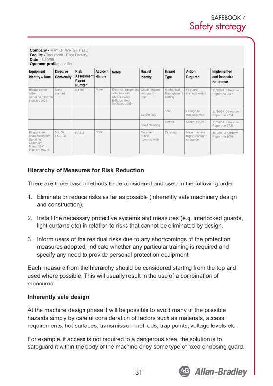
The following chart shown is a suggestion for part of a documented process ofaccounting for all safety aspects of the machinery being used. It acts as a guide formachinery users, but machine manufacturers or suppliers can also use the sameprinciple to confirm that all equipment has been evaluated. It will also act as anindex to more detailed reports on risk assessment.
It shows that where a machine carries the CE mark it simplifies the process as themachine hazards have already been evaluated by the manufacturer and that all thenecessary measures have been taken. Even with CE marked equipment there maystill be hazards due to the nature of its application or material being processedwhich the manufacturer did not foresee.
6
62
4
6
8
10
12
14
16
18
20
1
Final value withoutadjustments
6
62
4
6
8
10
12
14
16
18
20
12
Final value withadjustments
SAFEBOOK 4
Safety strategy
31
Hierarchy of Measures for Risk Reduction
There are three basic methods to be considered and used in the following order:
1. Eliminate or reduce risks as far as possible (inherently safe machinery designand construction),
2. Install the necessary protective systems and measures (e.g. interlocked guards,light curtains etc) in relation to risks that cannot be eliminated by design.
3. Inform users of the residual risks due to any shortcomings of the protectionmeasures adopted, indicate whether any particular training is required andspecify any need to provide personal protection equipment.
Each measure from the hierarchy should be considered starting from the top andused where possible. This will usually result in the use of a combination ofmeasures.
Inherently safe design
At the machine design phase it will be possible to avoid many of the possiblehazards simply by careful consideration of factors such as materials, accessrequirements, hot surfaces, transmission methods, trap points, voltage levels etc.
For example, if access is not required to a dangerous area, the solution is tosafeguard it within the body of the machine or by some type of fixed enclosing guard.
Company - MAYKIT WRIGHT LTDFacility - Tool room - East Factory.Date - 8/29/95Operator profile - skilled.
Equipment Identity & Date
Bloggs center lathe.Serial no. 8390726Installed 1978
Bloggs turret head milling m/cSerial no 17304294Manuf 1995Installed May 95
Notes
Electrical equipment complies with BS EN 60204E-Stops fitted (replaced 1989)
Hazard Type
Mechanical EntanglementCutting
Toxic
Cutting
Crushing
Action Required
Fit guard interlock switch
Change to non toxic type
Supply gloves
Move machineto give enoughclearance
Implemented and Inspected -Reference
11/25/94 J KershawReport no 9567
11/30/94 J KershawReport no 9714
11/30/94 J KershawReport no 9715
4/13/95 J KershawReport no 10064
Hazard Identity
Chuck rotation with guard open
Cutting fluid
Swarf cleaning
Movementof bed(towards wall)
AccidentHistory
None
None
Risk AssessmentReport NumberRA302
RA416
Directive Conformity
Noneclaimed
M/c Dir.EMC Dir

32
SAFEBOOK 4
Safety related control systems for machinery
Protective systems and measures
If access is required, then life becomes a little more difficult. It will be necessary toensure that access can only be gained while the machine is safe. Protectivemeasures such as interlocked guard doors and/or trip systems will be required. Thechoice of protective device or system should be heavily influenced by the operatingcharacteristics of the machine. This is extremely important as a system that impairsmachine efficiency will render itself liable to unauthorized removal or bypassing.
The safety of the machine in this case will depend on the proper application andcorrect operation of the protective system even under fault conditions.
The correct operation of the system must now be considered. Within each typethere is likely to be a choice of technologies with varying degrees of performance offault monitoring, detection or prevention.
In an ideal world every protective system would be perfect with absolutely nopossibility of failing to a dangerous condition. In the real world, however, we areconstrained by the current limits of knowledge and materials. Another very realconstraint is cost. Based on these factors it becomes obvious that a sense ofproportion is required. Common sense tells us that it would be ridiculous to insistthat the integrity of a safety system on a machine that may, at the worst case, causemild bruising to be the same as that required to keep a jumbo jet in the air. Theconsequences of failure are drastically different and therefore we need to havesome way of relating the extent of the protective measures to the level of riskobtained at the risk estimation stage.
Whichever type of protective device is chosen it must be remembered that a “safetyrelated system” may contain many elements including the protective device, wiring,power switching device and sometimes parts of the machine’s operational controlsystem. All these elements of the system (including guards, mounting, wiring etc.)should have suitable performance characteristics relevant to their design principleand technology. IEC/EN 62061 and EN ISO 13849-1 classify hierarchical levels ofperformance for safety related parts of control systems and they provide riskassessment methods in their annexes to determine the integrity requirements for aprotective system.
EN ISO 13849-1:2008 provides an enhanced risk graph in its Annex A.

SAFEBOOK 4
Safety strategy
33
IEC 62061 also provides a method in its Annex A, it takes the form shown below.
The use of either of the above methods should provide equivalent results. Eachmethod is intended to take account of the detailed content of the standard to whichit belongs.
Docu me nt No .: Risk assessment and safety measures Part of :
Pr e ri sk asse ssm en t Interm ed ia te risk a sse ssm en t Fo ll ow up ri sk asse ssm en t
Consequence s S everit ySe
Death, los in g an ey e or ar m 4 <= 1 ho u r 5 C om mo n 5 P erm anent, lo si ng fi nger s 3 > 1 h - <=d a y 5 L ik el y 4 Rev e rsi bl e, me dical attent io n 2 >1da y - <= 2w ks 4 P o ssi bl e 3 Im possReversi bl e, fi rst ai d 1 > 2w ks - <= 1 y r 3 R arel y 2 Po ssi
> 1 y r 2 N egl igible 1 Lik e
Ser. Hz d. Ha za rd Safety me as ur eNo. No .
Com me nt s
Avoiddurati on , F r ev en t , P r A
Freq uenc y an d P robabil it y of hz d.
Product:
Date: I ssued by :
Black area = Safety measures require d
Cl a ss Cl 14 - 15 3 - 4 5 - 7 8 - 10 11 - 13
SIL 2 OM
SI L 2
SIL 1
Fr
Gr e y area = Sa fe t y me asures reco mm ended
Cl Se P r Av
SI L 2 SI L 1 OM
SIL 2 S IL 3 S IL 3 SIL 1 S IL 2 S IL 3 OM
Must be determined for each safety function!
S = SeverityF = Frequency or Duration of ExposureP = Avoidance Probability
P2
P1P2
P1
P2
P1P2
P1
F2
F1
F2
F1
S2
S1
Low
High
b
a
c
d
e
PerformanceLevel, PLr
Contribution toRisk Reduction
Start

34
SAFEBOOK 4
Safety related control systems for machinery
In both cases it is extremely important that the guidance provided in the text of thestandard is used. The Risk Graph or Table must not be used in isolation or in anoverly simplistic manner.
Evaluation
After the protective measure has been chosen and before it is implemented it isimportant to repeat the risk estimation. This is a procedure that is often missed. Itmay be that if we install a protective measure, the machine operator may feel thatthey are totally and completely protected against the original envisaged risk.Because they no longer have the original awareness of danger, they may intervenewith the machine in a different way. They may be exposed to the hazard more often,or they may enter further into the machine for example. This means that if theprotective measure fails they will be at a greater risk than envisaged before. This isthe actual risk that we need to estimate. Therefore the risk estimation needs to berepeated taking into account any foreseeable changes in the way that people mayintervene with the machine. The result of this activity is used to check whether theproposed protective measures are, in fact, suitable. For further information Annex Aof IEC/EN 62061 is recommended.
Training, personal protective equipment etc.
It is important that operators have the necessary training in the safe workingmethods for a machine. This does not mean that the other measures can beomitted. It is not acceptable to merely tell an operator that they must not go neardangerous areas (as an alternative to guarding them).
It may also be necessary for the operator to use equipment such as special gloves,goggles, respirators, etc. The machinery designer should specify what sort ofequipment is required. The use of personal protective equipment will not usuallyform the primary safeguarding method but will complement the measures shownabove.

SAFEBOOK 4
Safety strategy
35
Standards
Many standards and technical reports provide guidance on risk assessment. Someare written for wide applicability, and some are written for specific applications. Thefollowing is a list of standards that include information on risk assessment.
ANSI B11.TR3: Risk assessment and risk reduction—A guide to estimate, evaluateand reduce risks associated with machine tools
ANSI PMMI B155.1: Safety Requirements for Packaging Machinery and Packaging-Related Converting Machinery
ANSI RIA R15.06: Safety Requirements for Industrial Robots and Robot Systems
AS 4024.1301-2006: Principles of risk assessment CSA Z432-04: Safeguarding ofMachinery
CSA Z434-03: Industrial Robots and Robot Systems—General Safety Requirements
IEC/EN 61508: Functional safety of electrical, electronic and programmableelectronic safety-related systems.
IEC/EN 62061: Safety of machinery—Functional safety of safety related electrical,electronic and programmable electronic control systems.
EN ISO 13849-1: Safety of machinery—Safety related parts of control systems
EN ISO 14121-1: Principles for risk assessment
ISO TR 14121-2: Risk assessment—Practical guidance and examples of methods.

36
SAFEBOOK 4
Safety related control systems for machinery
Protective Measures and Complimentary Equipment
When the risk assessment shows that a machine or process carries a risk of injury,the hazard must be eliminated or contained. The manner in which this is achievedwill depend on the nature of the machine and the hazard. Protective measures inconjunction with guarding either prevent access to a hazard or prevent dangerousmotion at a hazard when access is available. Typical examples of protectivemeasures are interlocked guards, light curtains, safety mats, two-hand controls andenabling switches.
Emergency stop devices and systems are associated with safety related controlsystems but they are not direct protective systems, they should only be regarded ascomplementary protective measures.
Preventing Access with Fixed Enclosing Guards
If the hazard is on a part of the machinery which does not require access, a guardshould be permanently fixed to the machinery. These types of guards must requiretools for removal. The fixed guards must be able to 1) withstand their operatingenvironment, 2) contain projectiles where necessary, and 3) not create hazards byhaving, for example, sharp edges. Fixed guards may have openings where theguard meets the machinery or openings due to the use of a wire mesh typeenclosure.
Windows provide convenient ways to monitor machine performance, when accessto that portion of the machine. Care must be taken in the selection of the materialused, as chemical interactions with cutting fluids, ultra-violet rays and simple agingcause the window materials to degrade over time.
The size of the openings must prevent the operator from reaching the hazard. TableO-10 in U.S. OHSA 1910.217 (f) (4), ISO 13854, Table D-1 of ANSI B11.19, Table 3in CSA Z432, and AS4024.1 provide guidance on the appropriate distance a specificopening must be from the hazard.
Detecting Access
Protective measures can be used to detect access to a hazard. When detection isselected as the method of risk reduction, the designer must understand that acomplete safety system must be used; the safeguarding device, by itself, does notprovide necessary risk reduction.

SAFEBOOK 4
Protective measures and equipment
37
This safety system generally consists of three blocks: 1) an input device that sensesthe access to the hazard, 2) a logic device that process the signals from the sensingdevice, checks the status of the safety system and turns on or off output devices,and 3) an output device that controls the actuator (for example, a motor).
Detection Devices
Many alternative devices are available to detect the presence of a person enteringor inside a hazard area. The best choice for a particular application is dependent ona number of factors.
• Frequency of access,• Stopping time of hazard,• Importance of completing the machine cycle, and• Containment of projectiles, fluids, mists, vapors, etc.
Appropriately selected movable guards can be interlocked to provide protectionagainst projectiles, fluids, mists and other types of hazards, and are often usedwhen access to the hazard is infrequent. Interlocked guards can also be locked toprevent access while the machine is in the middle of the cycle and when themachine takes a long time to come to a stop.
Presence sensing devices, like light curtains, mats and scanners, provide quick andeasy access to the hazard area and are often selected when operators mustfrequently access the hazard area. These types of devices do not provide protectionagainst projectiles, mists, fluids, or other types of hazards.
The best choice of protective measure is a device or system that provides themaximum protection with the minimum hindrance to normal machine operation. Allaspects of machine use must be considered, as experience shows that a systemthat is difficult to use is more liable to be removed or by-passed.
Presence Sensing Devices
When deciding how to protect a zone or area it is important to have a clearunderstanding of exactly what safety functions are required. In general there will beat least two functions.
• Switch off or disable power when a person enters the hazard area.• Prevent switching on or enabling of power when a person is in the hazard area.
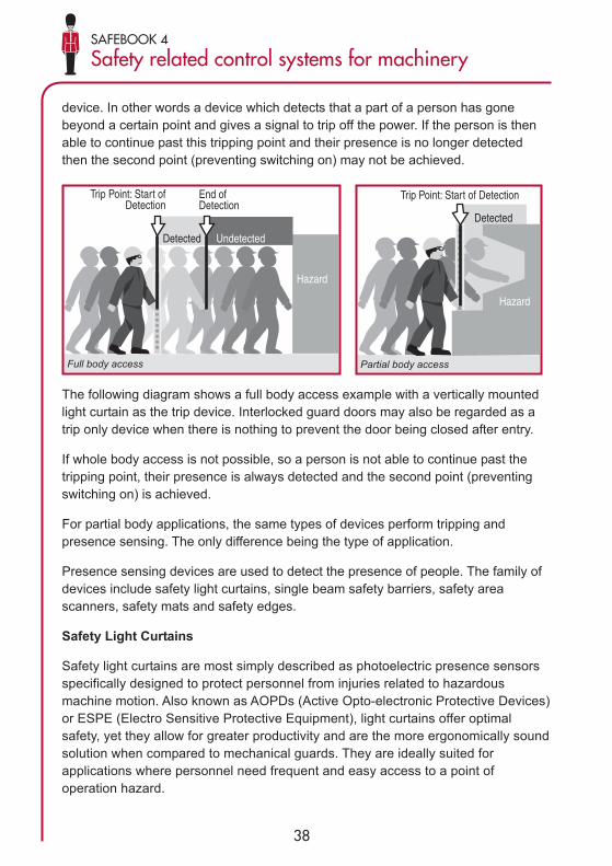
At first thought these may seem to be one and the same thing but although they areobviously linked, and are often achieved by the same equipment, they are actuallytwo separate functions. To achieve the first point we need to use some form of trip
38
SAFEBOOK 4
Safety related control systems for machinery
device. In other words a device which detects that a part of a person has gonebeyond a certain point and gives a signal to trip off the power. If the person is thenable to continue past this tripping point and their presence is no longer detectedthen the second point (preventing switching on) may not be achieved.
The following diagram shows a full body access example with a vertically mountedlight curtain as the trip device. Interlocked guard doors may also be regarded as atrip only device when there is nothing to prevent the door being closed after entry.
If whole body access is not possible, so a person is not able to continue past thetripping point, their presence is always detected and the second point (preventingswitching on) is achieved.
For partial body applications, the same types of devices perform tripping andpresence sensing. The only difference being the type of application.
Presence sensing devices are used to detect the presence of people. The family ofdevices include safety light curtains, single beam safety barriers, safety areascanners, safety mats and safety edges.
Safety Light Curtains
Safety light curtains are most simply described as photoelectric presence sensorsspecifically designed to protect personnel from injuries related to hazardousmachine motion. Also known as AOPDs (Active Opto-electronic Protective Devices)or ESPE (Electro Sensitive Protective Equipment), light curtains offer optimalsafety, yet they allow for greater productivity and are the more ergonomically soundsolution when compared to mechanical guards. They are ideally suited forapplications where personnel need frequent and easy access to a point ofoperation hazard.
Trip Point: Start ofDetection
End of Detection
Detected Undetected
Hazard
Full body access
Trip Point: Start of Detection
Detected
Hazard
Partial body access
SAFEBOOK 4
Protective measures and equipment
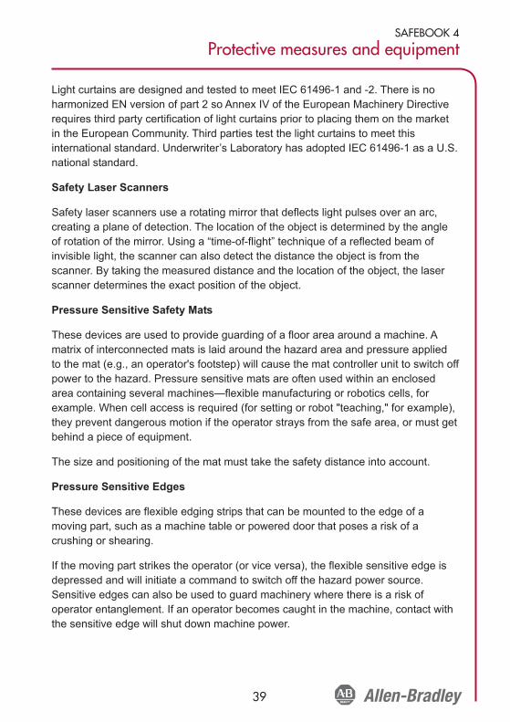
39
Light curtains are designed and tested to meet IEC 61496-1 and -2. There is noharmonized EN version of part 2 so Annex IV of the European Machinery Directiverequires third party certification of light curtains prior to placing them on the marketin the European Community. Third parties test the light curtains to meet thisinternational standard. Underwriter’s Laboratory has adopted IEC 61496-1 as a U.S.national standard.
Safety Laser Scanners
Safety laser scanners use a rotating mirror that deflects light pulses over an arc,creating a plane of detection. The location of the object is determined by the angleof rotation of the mirror. Using a “time-of-flight” technique of a reflected beam ofinvisible light, the scanner can also detect the distance the object is from thescanner. By taking the measured distance and the location of the object, the laserscanner determines the exact position of the object.
Pressure Sensitive Safety Mats
These devices are used to provide guarding of a floor area around a machine. Amatrix of interconnected mats is laid around the hazard area and pressure appliedto the mat (e.g., an operator's footstep) will cause the mat controller unit to switch offpower to the hazard. Pressure sensitive mats are often used within an enclosedarea containing several machines—flexible manufacturing or robotics cells, forexample. When cell access is required (for setting or robot "teaching," for example),they prevent dangerous motion if the operator strays from the safe area, or must getbehind a piece of equipment.
The size and positioning of the mat must take the safety distance into account.
Pressure Sensitive Edges
These devices are flexible edging strips that can be mounted to the edge of amoving part, such as a machine table or powered door that poses a risk of acrushing or shearing.
If the moving part strikes the operator (or vice versa), the flexible sensitive edge isdepressed and will initiate a command to switch off the hazard power source.Sensitive edges can also be used to guard machinery where there is a risk ofoperator entanglement. If an operator becomes caught in the machine, contact withthe sensitive edge will shut down machine power.

40
SAFEBOOK 4
Safety related control systems for machinery
There are a number of technologies used to create safety edges. One populartechnology is to insert essentially what is a long switch inside the edge. This approachprovides straight edges and generally uses the 4-wire connection technique.
Light curtains, scanners, floor mats and sensitive edges are classified as "tripdevices." They do not actually restrict access but only "sense" it. They rely entirelyon their ability to both sense and switch for the provision of safety. In general theyare only suitable on machinery which stops reasonably quickly after switching off thepower source. Because an operator can walk or reach directly into the hazard areait is obviously necessary that the time taken for the motion to stop is less than thatrequired for the operator to reach the hazard after tripping the device.
Safety Switches
When access to the machine is infrequent, movable (operable) guards arepreferred. The guard is interlocked with the power source of the hazard in a mannerwhich ensures that whenever the guard door is not closed the hazard power will beswitched off. This approach involves the use of an interlocking switch fitted to theguard door. The control of the power source of the hazard is routed through theswitch section of the unit. The power source is usually electrical but it could also bepneumatic or hydraulic. When guard door movement (opening) is detected theinterlocking switch will initiate a command to isolate the hazard power supply eitherdirectly or via a power contactor (or valve).
Some interlocking switches also incorporate a locking device that locks the guarddoor closed and will not release it until the machine is in a safe condition. For themajority of applications the combination of a movable guard and an interlock switchwith or without guard locking is the most reliable and cost effective solution.
There is a wide variety of safety switch options including:
• Tongue Interlock Switches - these devices require a tongue-shapedactuator to be inserted and removed from the switch for operation
• Hinge Interlock Switches - these devices are placed on the hinge-pin of aguard door and utilize the opening action of the guard to actuate.
• Guardlocking Switches - In some applications, locking the guard closed ordelaying the opening of the guard is required. Devices suitable for thisrequirement are called guardlocking interlock switches. They are suited tomachines with run down characteristics but they can also provide asignificant increase of protection level for most types of machines.

SAFEBOOK 4
Protective measures and equipment
41
• Non-contact Interlock Switches - these devices require no physical contactto actuate with some versions incorporating a coding function for increasedresistance to tampering.
• Position (Limit Switch) Interlocks - Cam operated actuation usually takesthe form of a positive mode limit (or position) switch and a linear or rotarycam. It is generally used on sliding guards.
• Trapped Key Interlocks - Trapped keys can perform control interlocking aswell as power interlocking. With “control interlocking,” an interlock deviceinitiates a stop command to an intermediate device, which turns off asubsequent device to disconnect the energy from the actuator. With “powerinterlocking,” the stop command directly interrupts the energy supply to themachine actuators.
Operator Interface Devices
Stop Function - In the U.S., Canada, Europe and at the international level,harmonization of standards exist with regard to the descriptions of stop categoriesfor machines or manufacturing systems.
NOTE: these categories are different to the categories from EN 954-1 (ISO 13849-1). See standards NFPA79 and IEC/EN60204-1 for further details. Stops fall intothree categories:
Category 0 is stopping by immediate removal of power to the machine actuators.This is considered an uncontrolled stop. With power removed, braking actionrequiring power will not be effective. This will allow motors to free spin and coast toa stop over an extended period of time. In other cases, material may be dropped bymachine holding fixtures, which require power to hold the material. Mechanicalstopping means, not requiring power, may also be a used with a category 0 stop.The category 0 stop takes priority over category 1 or category 2 stops.
Category 1 is a controlled stop with power available to the machine actuators toachieve the stop. Power is then removed from the actuators when the stop isachieved. This category of stop allows powered braking to quickly stop hazardousmotion, and then power can be removed from the actuators.
Category 2 is a controlled stop with power left available to the machine actuators. Anormal production stop is considered a category 2 stop.
These stop categories must be applied to each stop function, where the stopfunction is the action taken by the safety related parts of the control system in
42
SAFEBOOK 4
Safety related control systems for machinery
response to an input, category 0 or 1 should be used. Stop functions must overriderelated start functions. The selection of the stop category for each stop functionmust be determined by a risk assessment.
Emergency Stop Function
The emergency stop function must operate as either a category 0 or category 1stop, as determined by a risk assessment. It must be initiated by a single humanaction. When executed, it must override all other functions and machine operatingmodes. The objective is to remove power as quickly as possible without creatingadditional hazards.
Until recently, hardwired electro-mechanical components were required for e-stopcircuits. Recent changes to standards such as IEC 60204-1 and NFPA 79 mean thatsafety PLCs and other forms of electronic logic meeting the requirements ofstandards like IEC61508, can be used in the e-stop circuit.
Emergency Stop Devices
Wherever there is a danger of an operator getting into trouble on a machine theremust be a facility for fast access to an emergency stop device. The e-stop devicemust be continuously operable and readily available. Operator panels shouldcontain at least one e-stop device. Additional e-stop devices may be used at otherlocations as needed. E-Stop devices come in various forms. Pushbutton switchesand cable pull switches are examples of the more popular type devices. When thee-stop device is actuated, it must latch in and it must not be possible to generate thestop command without latching in. The resetting of the emergency stop device mustnot cause a hazardous situation. A separate and deliberate action must be used tore-start the machine.
For further information on e-stop devices, read ISO/EN13850, IEC 60947-5-5,NFPA79 and IEC60204-1, AS4024.1, Z432-94.
Emergency Stop Buttons
Emergency stop devices are considered complimentary safeguarding equipment.They are not considered primary safeguarding devices because they do not preventaccess to a hazard nor do they detect access to a hazard.
The usual way of providing this is in the form of a red-colored mushroom-headedpush button on a yellow background which the operator strikes in the event of anemergency. They must be strategically placed in sufficient quantity around themachine to ensure that there is always one in reach at a hazard point.

SAFEBOOK 4
Protective measures and equipment
43
E-Stop buttons must be readily accessible and must be available in all modes ofmachine operation. When a pushbutton is used as an e-stop device, it must be amushroom (or palm operated) shaped, red colored, with a yellow background. Whenthe button is pressed, the contacts must change state at the same time the buttonlatches in the depressed position.
One of the latest technologies to be applied to e-stops is a self-monitoring technique.An additional contact is added to the back estop that monitors whether the back of thepanel components are still present. This is known as a self-monitoring contact block. Itconsists of a spring actuated contact that closes when the contact block is snappedinto place onto the panel. Figure 80 shows the self-monitoring contact connected inseries with one of the direct opening safety contacts.
Cable Pull Switches
For machinery such as conveyors, it is often more convenient and effective to use acable pull device along the hazard area as the emergency stop device. Thesedevices use a steel wire rope connected to latching pull switches so that pulling onthe rope in any direction at any point along its length will trip the switch and cut offthe machine power.
The cable pull switches must detect both a pull on the cable as well as when the cablegoes slack. Slack detection ensures that the cable is not cut and is ready for use.
Cable distance affects performance of the switch. For short distances, the safetyswitch is mounted on one end and a tension spring mounted at the other. For longerdistances, a safety switch must be mounted at both ends of the cable to ensure thata single action by the operator initiates a stop command. The required cable pullforce should not exceed 200N (45lbs) or a distance of 400mm (15.75in) at a positioncentered between two cable supports.
Two-Hand Controls
The use of two-hand controls (also referred to as bi-manual controls) is a commonmethod of preventing access while a machine is in a dangerous condition. Twocontrols must be operated concurrently (within 0.5 s of each other) to start themachine. This ensures that both hands of the operator are occupied in a safe position(i.e., at the controls) and therefore cannot be in the hazard area. The controls must beoperated continuously during the hazardous conditions. Machine operation mustcease when either of the controls are released, if one control is released, the othercontrol must also be released before the machine can be restarted.

44
SAFEBOOK 4
Safety related control systems for machinery
A two-hand control system depends heavily on the integrity of its control andmonitoring system to detect any faults, so it is important that this aspect is designedto the correct specification. Performance of the two-hand safety system ischaracterized into Types by ISO 13851 (EN 574) as shown and they are related tothe Categories from ISO 13849-1. The types most commonly used for machinerysafety are IIIB and IIIC. The table below shows the relationship of the types to thecategories of safety performance.
The physical design spacing should prevent improper operation (e.g., by hand andelbow). This can be accomplished by distance or shields. The machine should notgo from one cycle to another without the releasing and pressing of both buttons.This prevents the possibility of both buttons being blocked, leaving the machinerunning continuously. Releasing of either button must cause the machine to stop.
The use of two-hand control should be considered with caution as it usually leavessome form of risk exposed. The two-hand control only protects the person usingthem. The protected operator must be able to observe all access to the hazard, asother personnel may not be protected.
ISO 13851 (EN574) provides additional guidance on two-hand control.
Enabling Devices
Enabling devices are controls that allow an operator to enter a hazard area with thehazard running only while the operator is holding the enabling device in the actuatedposition. Enabling devices use either two-position or three position types of switches.Two position types are off when the actuator is not operated, and are on when theactuator is operated. Three position switches are off when not actuated (position 1),on when held in the center position (position 2) and off when the actuator is operated
Requirements
Types
I IIIII
A B C
Synchronous actuation X X X
Use of Category 1 (from ISO 13849-1) X X
Use of Category 3 (from ISO 13849-1) X X
Use of Category 4 (from ISO 13849-1) X

SAFEBOOK 4
Protective measures and equipment
45
past the mid position (position 3). In addition, when returning from position 3 to 1, theoutput circuit must not close when passing through position 2.
Enabling devices must be used in conjunction with other safety related function. Atypical example is placing the motion is a controlled slow mode. Once in slow mode,an operator can enter the hazard area holding the enabling device.
When using an enabling device, a signal must indicate that the enabling device isactive.
Logic Devices
Logic devices play the central role of the safety related part of the control system.Logic devices perform the checking and monitoring of the safety system and eitherallow the machine to start or execute commands to stop the machine.
A range of logic devices are available to create a safety architecture that meets thecomplexity and the functionality required for the machine. Small hardwiredmonitoring safety relays are most economical for smaller machines where adedicated logic device is needed to complete the safety function. Modular andconfigurable monitoring safety relays are preferred where a large and diversenumber of safeguarding devices and minimal zone control are required. Themedium to large and more complex machine will find programmable systems withdistributed I/O to be preferable.
Monitoring Safety Relays
Monitoring safety relay (MSR) modules play a key role in many safety systems.These modules are usually comprised of two or more positively guided relays withadditional circuitry to ensure the performance of the safety function.
Positive guided relays are specialized “ice-cube” relays. Positively guided relaysmust meet the performance requirements of EN50025. Essentially, they aredesigned to prevent the normally closed and normally open contacts from beingclosed simultaneously. Newer designs replace the electromechanical outputs withsafety rated solid state outputs.
Monitoring safety relays perform many checks on the safety system. Upon power-up, they perform self-checks on their internal components. When the input devicesare activated, the MSR compares the results of redundant inputs. If acceptable, theMSR checks external actuators. If okay, the MSR awaits a reset signal to energizeits outputs.

46
SAFEBOOK 4
Safety related control systems for machinery
The selection of the appropriate safety relay is dependent on a number of factors:type of device it monitors, the type of reset, the number and type of outputs.
Inputs Types
Safeguarding devices have different types of methods of indicating something hashappened:
Contact Interlocks and E-stops: Mechanical contacts, single channel with onenormally closed contact or dual channel, both normally closed. The MSR must beable to accept single or dual channel and provide crossfault detection for the dualchannel arrangement.
Non-Contacts Interlocks and E-stops: Mechanical contacts, dual channel, onenormally open and one normally closed contact. The MSR must be able to processdiverse inputs.
Output Solid State Switching Devices: Light curtains, laser scanners, solid-statenon-contacts have two sourcing outputs and perform their own crossfault detection.The MSR must be able to ignore the devices crossfault detection method.
Pressure Sensitive Mats: Mats create a short circuit between two channels. TheMSR must be able to withstand the repeated short circuits.
Pressure Sensitive Edges: Some edges are designed like 4-wire mats. Some aretwo wire devices that create a change in resistance. The MSR must be able todetect a short circuit or the change resistance.
Voltage: Measures the Back EMF of a motor during rundown. The MSR must beable to tolerate high voltages as well as detect low voltages as the motor spins down.
Stopped Motion: The MSR must detect pulse streams from diverse, redundantsensors.
Two-hand Control: The MSR must detect normally open and normally closeddiverse inputs as well as provide 0.5s timing and sequencing logic.
Monitoring safety relays must be designed specifically to interface with each ofthese types of devices, as they have different electrical characteristics. Some MSRscan connect to a few different types of inputs, but once the device is chosen, theMSR can only interface with that device. The designer must select an MSR that iscompatible with the input device.

SAFEBOOK 4
Protective measures and equipment
47
Input Impedance
The input impedance of the monitoring safety relays determines how many inputdevices can be connected to the relay and how far away the input devices can bemounted. For example, a safety relay may have a maximum allowable inputimpedance of 500 ohms (~). When the input impedance is greater than 500~, it willnot switch on its outputs. Care must be taken by the user to ensure that the inputimpedance remains below the maximum specification. The length, size and type ofwire used affects input impedance.
Number of Input Devices
The risk assessment process should be used to help determine how many inputsdevices should be connected to a monitoring safety relay unit MSR and how oftenthe input devices should be checked. To assure that E-Stops and gate interlocks arein an operational state, they should be checked for operation at regular intervals, asdetermined by the risk assessment. For example, a dual channel input MSRconnected to an interlocked gate that must be opened every machine cycle (e.g.,several times per day) may not have to be checked. This is because opening theguard causes the MSR to check itself, its inputs and its outputs (depending onconfiguration) for single faults. The more frequent the guard opening the greater theintegrity of the checking process.
Another example might be E-Stops. Since E-Stops are typically used only foremergencies, they are likely to be rarely used. Therefore a program should beestablished to exercise the E Stops and confirm their effectiveness on a scheduledbasis. Exercising the safety system in this way is called performing a Proof Test, andthe time in between Proof Tests is called the Proof Test Interval. A third examplemight be access doors for machine adjustments, which like E-Stops might be rarelyused Here again a program should be established to exercise the checking functionon a scheduled basis.
The risk assessment will help determine whether the input devices need to bechecked and how often they should be checked. The higher the level of risk, thegreater integrity required of the checking process. And the less frequent the"automatic" checking, the more frequent should be the imposed "manual" check.
Input Crossfault Detection
In dual channel systems, channel-to-channel short circuit faults of the input devices,also known as crossfaults, must be detected by the safety system. This isaccomplished by the sensing device or the monitoring safety relay.

48
SAFEBOOK 4
Safety related control systems for machinery
Microprocessor based monitoring safety relays, like light curtains, laser scanners andthe advanced noncontact sensors detect these shorts in a variety of ways. Onecommon way of detecting crossfaults is by using diverse pulse testing. The outputsignals are pulsed very quickly. The channel 1 pulse is offset from the channel 2pulse. If a short occurs, the pulses occur concurrently and are detected by the device.
Electro-mechanical based monitoring safety relays employ a different diversity technique:one pull-up input and one pull-down input. A short from Channel 1 to Channel 2 will makethe overcurrent protection device active and the safety system will shut down.
Outputs
MSRs come with various numbers of outputs. The types of outputs help determinewhich MSR must be used in specific applications.
Most MSRs have at least 2 immediately operating safety outputs. MSR safetyoutputs are characterized as normally-open. These are safety rated due to theredundancy and internal checking. A second type of output is delayed outputs.Delayed outputs are typically used in Category 1 stops, where the machine requirestime to execute the stopping function before allowing access to the hazard area.MSRs also have auxiliary outputs. Generally these are considered normally closed.
Output Ratings
Output ratings describe the ability of the safeguarding device to switch loads.Typically, the ratings for industrial devices are described as resistive orelectromagnetic. A resistive load may be a heater type element. Electromagneticloads are typically relays, contactors, or solenoids; where there is a large inductivecharacteristic of the load. Annex A of standard IEC 60947-5-1, describes the ratingsfor loads. This is also shown in the Safety catalogue ‘principles’ section.
Designation Letter: The designation is a letter followed by a number, for exampleA300. The letter relates to the conventional enclosed thermal current and whetherthat current is direct or alternating. For example A represents 10 amps alternatingcurrent. The number stands for the rated insulation voltage. For example, 300represents 300V.
Utilization: The Utilization describes the types of loads the device is designed toswitch. The utilizations relevant to IEC 60947-5 are shown in the following table.

SAFEBOOK 4
Protective measures and equipment
49
Thermal Current, Ith: The conventional enclosed thermal current is the value ofcurrent used for the temperature-rise tests of the equipment when mounted in aspecified enclosure.
Rated Operational Voltage Ue and Current Ie; The rated operational current andvoltage specify the making and breaking capacities of the switching elements undernormal operating conditions. The Allen-Bradley Guardmaster products arespecifically rated at 125VAC, 250VAC and 24VDC. Consult the factory for usage atvoltages other than these specified ratings.
VA: The VA (Voltage x Amperage) ratings indicate the ratings of the switchingelements when making the circuit as well as breaking the circuit.
Example 1: An A150, AC-15 rating indicates that the contacts can make a 7200VAcircuit. At 120V AC, the contacts can make a 60 amp inrush circuit. Since the AC-15 isan electromagnetic load, the 60 amp is only for a short duration; the inrush current ofthe electromagnetic load. The breaking of the circuit is only 720 VA because the steadystate current of the electromagnetic load is 6A, which is the rated operational current.
Utilization Description of Load
AC-12 Control of resistive loads and solid state loadswith isolation by opto-couplers
AC-13 Control of solid state loads with transformerisolation
AC-14 Control of smallelectromagnetic loads(less than 72 VA)
AC-15 Electromagnetic loads greater than 72 VA
DC-12 Control of resistive loads and solid state loadswith isolation by opto-couplers
DC-13 Control of electromagnets
DC-14 Control of electromagnetic loads havingeconomy resistors in circuit

50
SAFEBOOK 4
Safety related control systems for machinery
Example 2: An N150, DC-13 rating indicates that the contacts can make a 275VAcircuit. At 125V AC, the contacts can make a 2.2 amp circuit. DC electromagneticloads do not have an inrush current like AC electromagnetic loads. The breaking ofthe circuit is also 275VA because the steady state current of the electromagneticload is 2.2, which is the rated operational current.
Machine Re-start
If, for example, an interlocked guard is opened on an operating machine, the safetyinterlock switch will stop that machine. In most circumstances it is imperative thatthe machine does not restart immediately when the guard is closed. A common wayof achieving this is to rely on a latching contactor start arrangement.
Pressing and releasing the start button momentarily energizes the contactor controlcoil which closes the power contacts. As long as power is flowing through the powercontacts the control coil is kept energized (electrically latched) via the contactor'sauxiliary contacts which are mechanically linked to the power contacts. Anyinterruption to the main power or control supply results in the de-energizing of thecoil and opening of the main power and auxiliary contacts. The guard interlock iswired into the contactor control circuit. This means that restart can only be achievedby closing the guard and then switching "ON" at the normal start button which resetsthe contactor and starts the machine.
The requirement for normal interlocking situations is made clear in ISO 12100-1Paragraph 3.22.4 (extract)
“When the guard is closed, the hazardous machine functions covered by the guardcan operate, but the closure of the guard does not by itself initiate their operation”.
Many machines already have either single or double contactors which operate asdescribed above (or have a system which achieves the same result). When fitting aninterlock to existing machinery it is necessary to determine whether the powercontrol arrangement meets this requirement and take additional measures ifnecessary.
Reset Functions
Allen Bradley Guardmaster monitoring safety relays are designed with eithermonitored manual reset or automatic/manual reset.

SAFEBOOK 4
Protective measures and equipment
51
Monitored Manual Reset
A monitored manual reset requires a change of state of the reset circuit after thegate is closed or the E-Stop is reset. The mechanically linked normally closedauxiliary contacts of the power switching contactors are connected in series with amomentary push button. After the guard has been opened and closed again, thesafety relay will not allow the machine to be restarted until there is a change of stateat the reset button. This is in compliance with the intent of the requirements foradditional manual reset as given in EN ISO 13849-1. i.e., the reset function ensuresthat both contactors are OFF and that both interlock circuits (and therefore theguards) are closed and also (because a change of state is required) that the resetactuator has not been bypassed or blocked in any way. If these checks aresuccessful the machine can then be restarted from the normal controls. EN ISO13849-1 cites the change of state from energized to de-energized but the sameprotective principle can also be achieved by the opposite effect.
The reset switch should be located in a place that provides a good view of the hazardso that the operator can check that the area is clear before operation
Auto/ Manual Reset
Some safety relays have automatic/manual reset. The manual reset mode is notmonitored and reset occurs when the button is pressed. A short circuited or jammedin reset switch will not be detected. With this approach it may not be possible toachieve the requirements for additional manual reset as given in EN ISO 13849-1unless additional means are used.
Alternatively the reset line can be jumpered allowing an automatic reset. The usermust then provide another mechanism for preventing machine start-up when thegate closes.
An auto-reset device does not require a manual switching action but after de-actuation it will always conduct a system integrity check before resetting the system.An auto-reset system should not be confused with a device without reset facilities. Inthe latter the safety system will be enabled immediately after de-actuation but therewill be no system integrity check.
The reset switch should be located in a place that provides a good view of thehazard so that the operator can check that the area is clear before operation.

52
SAFEBOOK 4
Safety related control systems for machinery
Control Guards
A control guard stops a machine when the guard is opened and directly starts itagain when the guard is closed. The use of control guards is only allowed undercertain stringent conditions because any unexpected start-up or failure to stop wouldbe extremely dangerous. The interlocking system must have the highest possiblereliability (it is often advisable to use guard locking). The use of control guards canONLY be considered on machinery where there is NO POSSIBILITY of an operatoror part of his body staying in or reaching into the danger zone while the guard isclosed. The control guard must be the only access to the hazard area.
Safety Programmable Logic Controls
The need for flexible and scaleable safety applications drove the development of safetyPLCs/controllers. Programmable safety controllers provide users the same level ofcontrol flexibility in a safety application that they are accustomed to with standardprogrammable controllers. However there are extensive differences between standardand safety PLCs. Safety PLCs come in various platforms to accommodate thescalability, functional and integration requirements of the more complex safety systems.
Multiple microprocessorsare used to process theI/O, memory, and safecommunications.Watchdog circuits performdiagnostic analysis. Thistype of construction isknown as 1oo2D,because either one of thetwo microprocessors canperform the safetyfunction, and extensivediagnostics are performedto ensure that bothmicroprocessors areoperating in sync.
Also, each input circuit is internally tested many times each second to make surethat it is operating correctly. You may only hit the E-Stop once a month; but whenyou do, the circuit has been continuously tested so that the EStop will be sensedcorrectly internal to the safety PLC.
AddressDataControl
Address
DataControl
Micro-processor
Micro-processor
SYNCWATCHDOG/
COMPARE
Flash RAM I/O ModulePorts
Flash RAM
1oo2D Architecture

SAFEBOOK 4
Protective measures and equipment
53
Safety PLC outputs are electromechanical or safety rated solid state. Like the inputcircuits, the output circuits are tested multiple times every second to make sure thatthey can turn the output off. If one of the three fails, the output is turned off by theother two, and the fault is reported by the internal monitoring circuit.
When using safety devices with mechanical contacts (E-stops, gate switches, etc),the user can apply pulse test signals to detect crossfaults. To not use up expensivesafety outputs, many safety PLCs provides specific pulsing outputs that can beconnected to mechanical contact devices.
Software
Safety PLCs program very much like standard PLCs do. All of the additionaldiagnostics and error checking mentioned earlier is done by the operating system,so the programmer is not even aware that it is happening. Most safety PLCs willhave special instructions used to write the program for the safety system, and theseinstructions tend to mimic the function of their safety relay counterparts. Forexample, the Emergency Stop instruction operates very much like an MSR 127.Though the logic behind each of these instructions is complex, the safety programslook relatively simple because the programmer simply connects these blockstogether. These instructions, along with other logical, math, data manipulation, etc.instructions are certified by a third party to ensure their operation is consistent withthe applicable standards.
AddressData
Control
Address
Data
Control
Micro-processor
Micro-processor
DataBuffers
TestControl Circuit
SYNC
Input 1Test
Test
Test
WATCHDOG/COMPARE
Input 2
Input 3
IO B
US
Safety input module block diagram

54
SAFEBOOK 4
Safety related control systems for machinery
Function blocks are the predominant methods for programming safety functions. Inaddition to Function Blocks and Ladder Logic, safety plc's also provide certifiedsafety application instructions. Certified safety instructions provide applicationspecific behavior. This example shows an emergency stop instruction. Toaccomplish the same function in ladder logic would require approximately 16 rungsof ladder logic. Since the logic behavior is embedded in the E-Stop instruction, theembedded logic does not have to be tested.
Certified function blocks are available to interface with almost all safety devices.One exception to this list is the safety edge that uses resistive technology.
Safety PLCs generate a “signature” that provides the ability to track whetherchanges were made. This signature is usually a combination of the program,input/output configuration, and a time stamp. When the program is finalized andvalidated, the user should record this signature as part of the validation results forfuture reference. If the program needs modification, revalidation is required and anew signature must be recorded. The program can also be locked with a passwordto prevent unauthorized changes.
Wiring is simplified with programmable logic systems as compared to monitoringsafety relays. Unlike wiring to specific terminals on monitoring safety relays, inputdevices are connected to any input terminals and output devices are connected toany output terminals. The terminals are then assigned through software.
Integrated Safety Controllers
Safety control solutions now provide complete integration within a single controlarchitecture where safety and standard control functions reside and work together.The ability to perform motion, drive, process, batch, high speed sequential, and SIL3 safety in one controller provides significant benefits. The integration of safety andstandard control provides the opportunity to utilize common tools and technologieswhich reduce costs associated with design, installation, commissioning andmaintenance. The ability to utilize common control hardware, distributed safety I/Oor devices on safety networks and common HMI devices reduce purchase andmaintenance costs, and also reduce development time. All of these featuresimprove productivity, the speed associated with troubleshooting and the lowering oftraining costs due to commonality.
The following diagram shows an example of the integration of control and safety.The standard non-safety related control functions reside in the Main Task. Thesafety related functions reside in the Safety Task.

SAFEBOOK 4
Protective measures and equipment
55
All standard and safety related functions are isolated from each other. For example,safety tags can be directly read by the standard logic. Safety tags can be exchangedbetween GuardLogix controllers over EtherNet, ControlNet or DeviceNet. Safety tagdata can be directly read by external devices, Human Machine Interfaces (HMI),personal computers (PC) or other controllers.
1. Standard tags and logic behave thesame as ControlLogix.
2. Standard tag data, program orcontroller scoped and external devices,HMI, PC’s, other controllers, etc.
3. As an integrated controller,GuardLogix provides the ability to move(map) standard tag data into safety tagsfor use within the safety task. This is toprovide users the ability read statusinformation from the standard side ofGuardLogix. This data must not be usedto directly control a safety output.
4. Safety tags can be directly read bystandard logic.
5. Safety tags can be read or written bysafety logic.
6. Safety tags can be exchangedbetween GuardLogix controllers overEtherNet.
7. Safety tag data, program orcontroller scoped can be read by external devices, HMI’s, PC’s, other controllers,etc. Note, once this data is read, it is considered standard data, not safety data.
IntegratedTasks

56
SAFEBOOK 4
Safety related control systems for machinery
Safety Networks
Plant floor communication networks have traditionally provided manufacturers thecapability to improve flexibility, increase diagnostics, increase distance, reduceinstallation & wiring cost, ease maintainability and generally improve the productivityof their manufacturing operations. These same motivations are also driving theimplementation of industrial safety networks. These safety networks allowmanufacturers to distribute safety I/O and safety devices around their machineryusing a single network cable, reducing installation costs while improving diagnosticsand enabling safety systems of increased complexity. They also enable safecommunications between safety PLCs / controllers, allowing users to distribute theirsafety control among several intelligent systems.
Safety networks do not prevent communication errors from occurring. Safetynetworks are more capable of detecting transmission errors and then allow safetydevices to take the appropriate actions. Communication errors that are detectedinclude: message insertion, message loss, message corruption, message delay,message repeat, and incorrect message sequence.
For most applications, when an error is detected the device will go to a known de-energized state, typically called a “safety state.” The safety input or output device isresponsible for detecting these communication errors and then going to the safestate if appropriate.
Early safety networks were tied to a particular media type or media access scheme,so manufacturers were required to use specific cables, network interface cards,routers, bridges, etc. that also became part of the safety function. These networkswere limited in that they only supported communication between safety devices.This meant that manufacturers were required to use two or more networks for theirmachine control strategy (one network for standard control and another for safetyrelated control) increasing installation, training and spare parts costs.
Modern safety networks allow a single network cable to communicate with safety andstandard control devices. CIP (Common Industrial Protocol) Safety is an open standardprotocol published by ODVA (Open DeviceNet Vendors Association) that allows forsafety communications between safety devices on DeviceNet, ControlNet andEtherNet/IP networks. Because CIP Safety is an extension to the standard CIP protocol,safety devices and standard devices can all reside on the same network. Users can alsobridge between networks containing safety devices, allowing them to subdivide safetydevices to fine-tune safety response times, or to simply make distribution of safetydevices easier. Because the safety protocol is solely the responsibility of the end

SAFEBOOK 4
Protective measures and equipment
57
devices (safety PLC / controller, safety I/O module, safety component), standard cables,network interface cards, bridges, and routers are used, eliminating any specialnetworking hardware and removing these devices from the safety function.
Output Devices
Safety Control Relays and Safety Contactors
Control Relays and Contactors are used to remove power from the actuator. Specialfeatures are added to control relays and contactors to provide the safety rating.
Mechanically linked normally closed contacts are used to feed back the status of thecontrol relays and contactors to the logic device. The use of mechanically linkedcontacts helps ensure the safety function. To meet the requirements of mechanicallylinked contacts, the normally closed and the normally open contacts cannot be in theclosed state at the same time. IEC 60947-5-1 defines the requirements formechanically linked contacts. If the normally open contacts were to weld, thenormally closed contacts remain open by at least 0.5mm. Conversely, if the normallyclosed contacts were to weld, then the normally open contacts remain open.
Safety systems must only be started at specific locations. Standard rated controlrelays and contactors allow the armature to be depressed to close the normallyopen contacts. On safety rated devices, the armature is protected from manualoverride to mitigate unexpected startup.
On safety control relays, the normally closed contact is driven by the main spanner.Safety contactors use an adder deck to locate the mechanically linked contacts. Ifthe contact block were to fall off the base, the mechanically linked contacts remainclosed. The mechanically linked contacts are permanently affixed to the safetycontrol relay or safety contactor. On the larger contactors, an adder deck isinsufficient to accurately reflect the status of the wider spanner. Mirrored contacts,shown in Figure 4.81 are located on either side of the contactor are used.
Dropout time of control relays or contactors play a role in the safety distancecalculation. Often, a surge suppressor is placed across the coil to improve the life ofthe contacts driving the coil. For AC powered coils, the drop out time is not affected.For DC powered coils, the drop out time is increased. The increase is dependent onthe type of suppression selected.
Control relays and contactors are designed to switch large loads, anywhere from 0.5Ato over 100A. The safety system operates on low currents. The feedback signalgenerated by the safety system logic device can be on the order of a few milliamps to

58
SAFEBOOK 4
Safety related control systems for machinery
tens of milliamps, usually at 24VDC. The safety control relays and safety contactorsuse gold plated bifurcated contacts to reliably switch this small current.
Overload Protection
Overload protection for motors is required by electrical standards. Diagnosticsprovided by the overload protection device enhances not only equipment safety butoperator safety as well. Technologies available today can detect fault conditions likean overload, phase loss, ground fault, stall, jam, under-load, current imbalance andover-temperature. Detecting and communicating abnormal conditions prior totripping help to improve production up time and help prevent operators andmaintenance people from unforeseen hazardous conditions
Drives and Servos
Safety rated drives and servos can be used to prevent rotational energy from beingdelivered to achieve a safety stop as well as an emergency stop.
AC drives achieve the safety rating with redundant channels to remove power to thegate control circuitry. One channel is the Enable signal, a hardware signal thatremoves the input signal to the gate control circuitry. The second channel is positiveguided relay that remove the power supply from the Gate control circuitry. Thepositive guided relay also provides a status signal back to the logic system. Thisredundant approach allows the safety rated drive to be applied in emergency stopcircuits without the need for a contactor.
The Servo achieves a result in a manner similar to the AC drives using redundantsafety signals are used to achieve the safety function. One signal interrupts thedrive to the Gate Control Circuitry. A second signal interrupts power to the powersupply of the Gate control circuitry. Two positive guided relays are used to removethe signals and provide feedback to the safety logic device as well.
Connection Systems
Connection systems add value by reducing the installation and maintenance costsof safety systems. Designs must take into account consideration of single channel,dual channel, dual channel with indication and multiple types of devices.
When a series connection of dual channel interlocks is needed, a distribution blockcan simplify installation. With an IP67 rating, these types of boxes can be mountedon the machine at remote locations. When a diverse set of devices is required, anArmorBlock Guard I/O box can be used. The inputs can be configured by softwareto accommodate various types of devices.

SAFEBOOK 4
Safety distance calculations
59
Safety Distance Calculation
Hazards must come to a safe state prior to an operator reaching the hazard. For thesafety distance calculation, there are two groups of standards that have proliferated.In this chapter, these standards are grouped as follows:
ISO EN: (ISO 13855 and EN 999)
US CAN (ANSI B11.19, ANSI RIA R15.06 and CAN/CSA Z434-03)
Formula
The minimum safety distance is dependent on the time required to process the Stopcommand and how far the operator can penetrate the detection zone beforedetection. The formula used throughout the world has the same form andrequirements. The differences are the symbols used to represent the variables andthe units of measure.
The formulas are:
ISO EN: S = K x T + C
US CAN: Ds = K x (Ts + Tc + Tr + Tbm) + Dpf
Where: Ds and S are the minimum safe distance from the danger zone to theclosest detection point
Directions of Approach
When considering the safety distance calculation where a light curtains or areascanner is used, the approach to the detection device must be taken intoconsideration. Three types of approaches are considered:
Normal – an approach perpendicular to the detection plane
Horizontal – an approach parallel to the detection plan
Angled – an angled approach to the detection zone.
Speed Constant
K is a speed constant. The value of the speed constant is dependent on movementsof the operator (i.e. hand speeds, walking speeds, and stride lengths). Thisparameter is based on research data showing that it is reasonable to assume a

60
SAFEBOOK 4
Safety related control systems for machinery
1600mm/sec (63in/s) hand speed of an operator while the body is stationary. Thecircumstances of the actual application must be taken into account. As a generalguideline, the approach speed will vary from 1600mm/s (63in/s) to 2500mm/sec(100in/s). The appropriate speed constant must be determined by the riskassessment.
Stopping Time
T is the overall stopping time of the system. The total time, in seconds, starts fromthe initiation of the stop signal to the cessation of the hazard. This time can bebroken down to its incremental parts (Ts, Tc, Tr and Tbm) for easier analysis. Ts isthe worst stopping time of the machine/equipment. Tc is the worst stopping time ofthe control system. Tr is the response time of the safeguarding device, including itsinterface. Tbm is additional stopping time allowed by the brake monitor before itdetects stop-time deterioration beyond the end users’ predetermined limits. Tbm isused with part revolution mechanical presses. Ts + Tc + Tr are usually measured bya stop-time measuring device if the values are unknown.
Depth Penetration Factors
The Depth Penetration Factors is represented by the symbols C and Dpf. It is themaximum travel towards the hazard before detection by the safeguarding device.Depth penetration factors will change depending on the type of device andapplication. Appropriate standard must be checked to determine the best depthpenetration factor. For a normal approach to a light curtain or area scanner, whoseobject sensitivity is less than 64mm (2.5in), the ANSI and Canadian standards use:
Dpf = 3.4 x (Object Sensitivity – 6.875mm), but not less than zero.
For a normal approach to a light curtain or area scanner, whose object sensitivity isless than 40mm (1.57in), the ISO and EN standards use:
C = 8 x (Object Sensitivity – 14 mm), but not less than 0
These two formulas have a cross over point at 19.3mm. For object sensitivity lessthan 19mm, the US CAN approach is more restrictive, as the light curtain or areascanner must be set back further from the hazard. For object sensitivities greaterthan 19.3mm, the ISO EN standard is more restrictive. Machine builders, who wantto build one machine for use throughout the world, must take the worst caseconditions from both equations.

SAFEBOOK 4
Safety distance calculations
61
Reach-Through Applications
When larger object sensitivities are used, the US CAN and ISO EN standards differslightly on the depth penetration factor and the object sensitivity. The ISO EN valueis 850mm where the US CAN value is 900mm. The standards also differ in theobject sensitivity. Where the ISO EN standard allows for 40 to 70mm, the US CANstandard allows up to 600mm.
Reach-Over Applications
Both standards agree that the minimum height of the lowest beam should be300mm, but differ with respect to the minimum height of the highest beam. The ISOEN states 900mm, whereas the US CAN states 1200mm. The value for the highestbeam seems to be moot. When considering this to be a reach-through application,the height of the highest beam will have to be much higher to accommodate anoperator in a standing position. If the operator can reach over the detection plane,then the reach over criteria applies.
Single or Multiple Beams
Single or multiple separate beams are further defined by the ISO EN standards. Thefigures below shows the “practical” heights of multiple beams above the floor. Thedepth penetration is 850mm for most cases and 1200mm for the single beamusage. In comparison, the US CAN approach takes this into account by the Reach-Through requirements. Getting over, under or around the single and multiple beamsmust always be taken into consideration.
# Beams Height above the floor - mm (in) C - mm (in)1 750 (29.5) 1200 (47.2)2 400 (5.7), 900 (35.4) 850 (33.4)3 300 (11.8), 700 (27.5), 1100 (43.3) 850 (33.4)4 300 (11.8), 600 (23.6), 900 (35.4), 1200 (47.2) 850 (33.4)
Distance Calculations
For the normal approach to light curtains, the safety distance calculation for the ISOEN and US CAN are close, but differences do exist. For the normal approach tovertical light curtains where the object sensitivity is a maximum of 40m, the ISO ENapproach requires two steps. First, calculate S using 2000 for the speed constant.
S = 2000 x T + 8 x (d -1 4)
The minimum distance that S can be is 100mm.

62
SAFEBOOK 4
Safety related control systems for machinery
A second step can be used when the distance is greater than 500mm. Then the valueof K can be reduced to 1600. When using K=1600, the minimum value of S is 500mm.
The US CAN approach uses a one step approach: Ds = 1600 x T * Dpf
This leads to differences greater than 5% between the standards, when theresponse time is less than 560ms.
Angled Approaches
Most applications of light curtains and scanners are mounted in vertical (normalapproach) or horizontal (parallel approach). These mountings are not consideredangled if they are within ±5° of the intended design. When the angle exceeds ±5°,the potential risks (e.g. shortest distance) of foreseeable approaches must be takeninto consideration. In general, angles greater than 30° from the reference plane (e.g.floor) should be consider normal and those less than 30 considered parallel.
Safety Mats
With safety mats, the safety distance must take into account the operators pace andstride. Assuming the operator is walking and the safety mats are mounted on thefloor. The operator’s first step onto the mat is a depth penetration factor of 1200mmor 48 in. If the operator must step up onto a platform, then the depth penetrationfactor can be reduced by a factor of 40% of the height of the step.
Example
Example: An operator uses a normal approach to a 14mm light curtain, which isconnected to a monitoring safety relay which is connected to a DC powered contactorwith a diode suppressor. The safety system response time, Tr, is 20 + 15 + 95 =130ms. The machine stopping time, Ts+Tc, is 170ms. A brake monitor is not used. TheDpf value is 1 inch, and the C value is zero. The calculation would be as follows
Dpf = 3.4 (14 - 6.875) = 1in (24.2mm) C = 8 (14-14) = 0
Ds = K x (Ts + Tc + Tr + Tbm) + Dpf S = K x T + CDs = 63 x (0.17 + 0.13 + 0) + 1 S = 1600 x (0,3) + 0Ds = 63 x (0.3) + 1 S = 480mm (18.9in)Ds = 18.9 + 1Ds = 19.9 in (505mm)
Therefore, the minimum safe distance the safety light curtain must be mounted fromthe hazard is 20 inches or 508mm, for a machine to be used anywhere in the world.

SAFEBOOK 4
Prevention of Unexpected Power-up
63
Prevention of unexpected power-up
Prevention of unexpected power-up is covered by many standards. Examplesinclude ISO14118, EN1037, ISO12100, OSHA 1910.147, ANSI Z244-1, CSA Z460-05, and AS 4024.1603. These standards have a common theme: the primarymethod of preventing unexpected power up is to remove the energy from thesystem and to lock the system in the off state. The purpose is to safely allow peopleto enter a machine’s danger zones.
Lockout / Tagout
New machines must be built with lockable energy isolating devices. The devices apply toall types of energy, including electrical, hydraulic, pneumatic, gravity, and lasers. Lockoutrefers to applying a lock to an energy isolating device. The lock must only be removed byits owner or by a supervisor under controlled conditions. When multiple individuals mustwork on the machine, each individual must apply their locks to the energy isolatingdevices. Each lock must be identifiable to its owner.
In the U.S., tagout is an alternative to lockout for older machines where a lockable devicehas never been installed. In this case, the machine is turned off and a tag is applied towarn all personnel to not start the machine while the tag holder is working on the machine.Beginning in 1990, machines that are modified must be upgraded to include a lockableenergy isolating device.
An energy isolating device is a mechanical device that physically prevents thetransmission or release of energy. These devices can take the form of a circuit breaker, adisconnect switch, a manually operated switch, a plug/socket combination or a manuallyoperated valve. Electrical isolating devices must switch all ungrounded supply conductorsand no pole can operate independently.
The purpose of lockout and tagout is to prevent the unexpected startup of the machine.Unexpected startup may be the result of various causes: a failure of the control system; aninappropriate action on a start control, sensor, contactor, or valve; a restoration of powerafter an interruption; or some other internal or external influences. After completion of thelockout or tagout process, the dissipation of the energy must be verified.
Safety Isolation Systems
Safety isolation systems execute an orderly shutdown of a machine and alsoprovide an easy method of locking off the power to a machine. This approach workswell for larger machines and manufacturing systems, especially when multipleenergy sources are located on a mezzanine level or at distant locations.

64
SAFEBOOK 4
Safety related control systems for machinery
Load Disconnects
For local isolation of electrical devices, switches can be placed just prior to thedevice that needs to be isolated and locked out. The Bulletin 194E Load Switchesare an example of a product that are capable of both isolation and lockout.
Trapped Key Systems
Trapped key systems are another method for implementing a lockout system. Manytrapped key systems start with an energy isolating device. When the switch is turnedoff by the “primary” key, the electrical energy to the machine is removed from all theungrounded supply conductors simultaneously. The primary key can then beremoved and taken to a location where machine access is needed. Variouscomponents can be added to accommodate more complex lockout arrangements.
Alternative Measures to Lockout
Lockout and tagout must be used during servicing or maintenance of the machines.Machine interventions during normal production operations are covered bysafeguarding. The difference between servicing/maintenance and normal productionoperations is not always clear.
Some minor adjustments and servicing tasks, which take place during normalproduction operations, do not necessarily require the machine to be locked out.Examples include loading and unloading materials, minor tool changes andadjustments, servicing lubrication levels, and removing waste material. These tasksmust be routine, repetitive, and integral to the use of the equipment for production,and the work is performed using alternative measures, like safeguarding, whichprovide effective protection. Safeguarding includes devices like interlocked guards,light curtains, and safety mats. Used with appropriate safety rated logic and outputdevices, operators can safety access the machine danger zones during normalproduction tasks and minor servicing.

SAFEBOOK 4
Safety Related Control Systems & Functional Safety
65
Safety Related Control Systems
Introduction
What is a safety related control system (often abbreviated SRCS)? It is that part ofthe control system of a machine that prevents a hazardous condition from occurring.It can be a separate dedicated system or it may be integrated with the normalmachine control system.
Its complexity will vary from a simple system, such as a guard door interlock switchand emergency stop switch connected in series to the control coil of powercontactor, to a compound system comprising both simple and complex devicescommunicating through software and hardware.
Safety related control systems are designed to perform safety functions. The SRCSmust continue to operate correctly under all foreseeable conditions. So what is asafety function; how do we design a system to achieve this; and when we havedone that, how do we show it?
Safety Function
A safety function is implemented by the safety-related parts of the machine controlsystem to achieve or maintain the equipment under control in a safe state withrespect to a specific hazard. A failure of the safety function can result in an immediateincrease of the risks of using the equipment; that is, a hazardous condition.
A machine must have at least one “hazard,” otherwise, it is not a machine. A“hazardous condition” is when a person is exposed to a hazard. A hazardouscondition does not imply that the person is harmed. The exposed person may beable to acknowledge the hazard and avoid injury. The exposed person may not beable to recognize the hazard, or the hazard may be initiated by unexpected startup.The main task of the safety system designer is to prevent hazardous conditions andto prevent unexpected startup.
The safety function can often be described with multi-part requirements. Forexample, the safety function initiated by an interlocking guard has three parts:
1. the hazards protected by the guard cannot operate until the guard is closed;
2. opening the guard will cause the hazard to stop if operational at the time ofthe opening; and
3. the closure of the guard does not restart the hazard protected by the guard.

66
SAFEBOOK 4
Safety related control systems for machinery
When stating the safety function for a specific application, the word “hazard” must bechanged to the specific hazard. The hazard must not be confused with the results ofthe hazard. Crushing, cutting, and burning are results of a hazard. An example of ahazard is a motor, ram, knife, torch, pump, laser, robot, end-effector, solenoid, valve,other type of actuator, or a mechanical hazard involving gravity.
In discussing safety systems, the phrase “at or before a demand is placed on thesafety function” is used. What is a demand on the safety function? Examples ofdemands placed on the safety function are the opening of an interlocked guard, thebreaking of a light curtain, the stepping onto a safety mat, or the pressing of an estop.An operator is demanding that the hazard either stop or remain de-energized if it isalready stopped.
The safety-related parts of the machine control system execute the safety function.The safety function is not executed by a single device, for example, just by the guard.The interlock on the guard sends a command to a logic device, which in turn, disablesan actuator. The safety function starts with the command and ends with theimplementation.
The safety system must be designed with a level of integrity that is commensuratewith the risks of the machine. Higher risks require higher integrity levels to ensure theperformance of the safety function. Machine safety systems can be classified intolevels of performance of their ability to ensure the performance of their safety functionor, in other words, their functional safety integrity level.
Functional Safety of Control Systems
Important: The standards and requirements considered in this section are relativelynew. Work is still being conducted by the drafting groups on some aspectsespecially with regard to clarification and combining some of these standards.Therefore it is possible that there will be some changes to some of the detail givenin these pages. For the latest information please refer to: http://www.ab.com/safety.
What is Functional Safety?
Functional safety is the part of the overall safety that depends on the correctfunctioning of the process or equipment in response to its inputs. IEC TR 61508-0provides the following example to help clarify the meaning of functional safety. “Forexample, an overtemperature protection device, using a thermal sensor in thewindings of an electric motor to de-energize the motor before they can overheat, is

SAFEBOOK 4
Safety Related Control Systems & Functional Safety
67
an instance of functional safety. But providing specialized insulation to withstandhigh temperatures is not an instance of functional safety (although it is still aninstance of safety and could protect against exactly the same hazard).” As anotherexample, compare hard guarding to an interlocked guard. The hard guarding is notconsidered “functional safety” although it may protect against access to the samehazard as an interlocked door. The interlocked door is an instance of functionalsafety. When the guard is opened, the interlock serves as an “input” to a system thatachieves a safe state. Similarly, personal protective equipment (PPE) is used as aprotective measure to help increase safety of personnel. PPE is not consideredfunctional safety.
Functional safety was a term introduced in IEC 61508:1998. Since then, the termhas sometimes been associated with only programmable safety systems. This is amisconception. Functional safety covers a broad range of devices that are used tocreate safety systems. Devices like interlocks, light curtains, safety relays, safetyPLCs, safety contactors, and safety drives are interconnected to form a safetysystem, which performs a specific safety-related function. This is functional safety.Therefore the functional safety of an electrical control system is highly relevant tothe control of hazards arising from moving parts of machinery.
Two types of requirements are necessary to achieve functional safety:
• the safety function and• the safety integrity.
Risk assessment plays a key role in developing the functional safety requirements.Task and hazard analysis leads to the function requirements for safety (i.e. thesafety function). The risk quantification yields the safety integrity requirements (i.e.the safety integrity or performance level).
Four of the most significant control system functional safety standards formachinery are:
1. IEC/EN 61508 “Functional safety of safety related electrical, electronic andprogrammable electronic control systems”
This standard contains the requirements and provisions that are applicable tothe design of complex electronic and programmable systems andsubsystems. The standard is generic so it is not restricted to the machinerysector.

68
SAFEBOOK 4
Safety related control systems for machinery
2. IEC/EN 62061 ”Safety of machinery - Functional safety of safety relatedelectrical, electronic and programmable electronic control systems”
This standard is the machinery specific implementation of IEC/EN 61508. Itprovides requirements that are applicable to the system level design of alltypes of machinery safety-related electrical control systems and also for thedesign of non-complex subsystems or devices. It requires that complex orprogrammable subsystems should satisfy IEC/EN 61508
3. EN ISO 13849-1:2008 ”Safety of machinery – Safety related parts of controlsystems”
This standard is intended to provide a direct transition path from thecategories of the previous EN 954-1.
4. IEC 61511 ”Functional safety — Safety instrumented systems for the processindustry sector”
This standard is the process sector specific implementation of IEC/EN 61508
The functional safety standards represent a significant step beyond the familiarexisting requirements such as Control Reliable and the Categories system of theprevious ISO 13849-1:1999 (EN 954-1:1996).
Categories will not disappear completely; they are also used in current EN ISO13849-1 which uses the functional safety concept and has introduced newterminology and requirements. It has significant additions and differences to the oldEN 954-1 (ISO 13849-1:1999). In this section we will refer to the current version asEN ISO 13849-1. (EN ISO 13849-1:2008 has the same text as ISO 13849-1:2006).
IEC/EN 62061 and EN ISO 13849-1:2008
IEC/EN 62061 and EN ISO 13849-1 both cover safety-related electrical controlsystems. It is intended that they will eventually be combined into one standard withcommon terminology. Both standards produce the same results but use differentmethods. They are intended to provide users with an option to choose the one mostsuitable for their situation. A user can choose to use either standard and they areboth harmonized under the European Machinery Directive.
The outputs of both standards are comparable levels of safety performance orintegrity. The methodologies of each standard have differences that are appropriatefor their intended users.

SAFEBOOK 4
Safety Related Control Systems & Functional Safety
69
The methodology in IEC/EN 62061 is intended to allow for complex safetyfunctionality which may be implemented by previously unconventional systemarchitectures. The methodology of EN ISO 13849-1 is intended to provide a moredirect and less complicated route for more conventional safety functionalityimplemented by conventional system architectures.
An important distinction between these two standards is the applicability to varioustechnologies. IEC/EN 62061 is limited to electrical systems. EN ISO 13849-1 can beapplied to pneumatic, hydraulic, mechanical as well as electrical systems.
Joint Technical Report on IEC/EN 62061 and EN ISO 13849-1
A joint report has been prepared within IEC and ISO to help users of both standards.
It explains the relationship between the two standards and explains how theequivalence can be drawn between PL (Performance level) of EN ISO 13849-1 andSIL (Safety Integrity Level) of IEC.EN 62061 both at system and subsystem level.
In order to show that both standards give equivalent results the report shows anexample safety system calculated according to the methodologies of bothstandards. The report also clarifies a number of issues that have been subject todifferent interpretations. Perhaps one of the most significant issues is the aspect offault exclusion.
In general, where PLe is required for a safety function to be implemented by asafety-related control system it is not normal to rely upon fault exclusions alone toachieve this level of performance. This is dependent upon the technology used andthe intended operating environment. Therefore it is essential that the designer takesadditional care on the use of fault exclusions as the PL requirement increases.
In general the use of fault exclusions is not applicable to the mechanical aspects ofelectromechanical position switches and manually operated switches (e.g. anemergency stop device) in order to achieve PLe in the design of a safety-relatedcontrol system. Those fault exclusions that can be applied to specific mechanical faultconditions (e.g. wear/corrosion, fracture) are described in Table A.4 of ISO 13849-2.
For example, a door interlocking system that has to achieve PLe will need toincorporate a minimum fault tolerance of 1 (e.g. two conventional mechanicalposition switches) in order to achieve this level of performance since it is notnormally justifiable to exclude faults, such as, broken switch actuators. However, itmay be acceptable to exclude faults, such as short circuit of wiring within a controlpanel designed in accordance with relevant standards.

70
SAFEBOOK 4
Safety related control systems for machinery
SIL and IEC/EN 62061
IEC/EN 62061 describes both the amount of risk to be reduced and the ability of acontrol system to reduce that risk in terms of SIL (Safety Integrity Level). There arethree SILs used in the machinery sector, SIL 1 is the lowest and SIL 3 is the highest.
Because the term SIL is applied in the same manner in other industrial sectors suchas petro-chemicals, power generation and railways, IEC/EN 62061 is very usefulwhen machinery is used within those sectors. Risks of greater magnitude can occurin other sectors such as the process industry and for that reason IEC 61508 and theprocess sector specific standard IEC 61511 include SIL 4.
A SIL applies to a safety function. The subsystems that make up the system thatimplements the safety function must have an appropriate SIL capability. This issometimes referred to as the SIL Claim Limit (SIL CL). A full and detailed study ofIEC/EN 62061 is required before it can be correctly applied.
PL and EN ISO 13849-1:2008
EN ISO 13849-1:2008 will not use the term SIL; instead it will use the term PL(Performance Level). In many respects PL can be related to SIL. There are fiveperformance levels, PLa is the lowest and PLe is the highest.
Comparison of PL and SIL
This table shows the approximate relationship between PL and SIL when applied totypical circuit structures.
Approximate correspondence between PL and SIL
IMPORTANT: The table shown above is for general guidance and must NOT be usedfor conversion purposes. The full requirements of the standards must be referenced.
PL(Performance Level)
PFHD
(Probability of dangerousfailure per hour)
SIL(Safety Integrity
Level)
a ≥10–5 to <10–4 None
b ≥3 x 10⁻⁶ to <10–5 1
c ≥10–6 to <3 x 10⁻⁶ 1
d ≥10–7 to <10–6 2
e ≥10–8 to <10–7 3

SAFEBOOK 4
System design according to EN ISO 13849-1:2008
71
System design according to EN ISO 13849 and SISTEMA
A full and detailed study of EN ISO 13849-1:2008 is required before it can becorrectly applied. The following is a brief overview:
This standard provides requirements for the design and integration of safety-relatedparts of control systems, including some software aspects. The standard applies to asafety-related system but can also be applied to the component parts of the system.
SISTEMA Software PL Calculation Tool
SISTEMA is a software tool for the implementation of EN ISO 13849-1. Its use willgreatly simplify the implementation of the standard.
SISTEMA stands for "Safety Integrity Software Tool for the Evaluation of MachineApplications" It was developed by the BGIA in Germany and is free for use. Itrequires the input of various types of functional safety data as described later in thissection.
The Data can be input manually or automatically by using a Manufacturer’sSISTEMA Data Library.
The Rockwell Automation SISTEMA Data Library is available for download, togetherwith a link to the SISTEMA download site, at:www.discoverrockwellautomation.com/safety
Overview of EN ISO 13849-1
This standard has wide applicability, as it applies to all technologies, includingelectrical, hydraulic, pneumatic and mechanical. Although ISO 13849-1 is applicableto complex systems, it also refers the reader to IEC 62061 and IEC 61508 forcomplex software embedded systems.
Let's have look at what are the basic differences between the old EN 954-1 and thenew EN ISO 13849-1. The outputs of the old standard were Categories [B, 1, 2, 3 or4]. The outputs of the new standard are Performance Levels [PL a, b, c, d or e]. TheCategory concept is retained but there are additional requirements to be satisfiedbefore a PL can be claimed for a system.

72
SAFEBOOK 4
Safety related control systems for machinery
The requirements can be listed in basic form as follows:
• The architecture of the system. Essentially this captures what wehavebecome used to as the Categories
• Reliability data is required for the constituent parts of the system
• The Diagnostic Coverage [DC] of the system is required. This effectivelyrepresents the amount of fault monitoring in the system
• Protection against common cause failure
• Protection against systematic faults
• Where relevant, specific requirements for software
Later we will take a closer look at these factors but before we do it will be useful toconsider the basic intent and principle of the whole standard. It is clear at this stagethat there are new things to learn but the detail will make more sense once we haveunderstood what it is trying to achieve and why.
First of all why do we need the new standard? It is obvious that the technology usedin machine safety systems has progressed and changed considerably over the lastten years. Until relatively recently safety systems have depended on “simple”equipment with very foreseeable and predictable failure modes. More recently wehave seen an increasing use of more complex electronic and programmable devicesin safety systems. This has given us advantages in terms of cost, flexibility andcompatibility but it has also meant that the pre-existing standards are no longeradequate. In order to know whether a safety system is good enough we need toknow more about it. This is why the new standard asks for more information. Assafety systems start to use a more "black box" approach we start to rely moreheavily on their conformity to standards. Therefore those standards need to becapable of properly interrogating the technology. In order to fulfill this they mustspeak to the basic factors of reliability, fault detection, architectural and systematicintegrity. This is the intent of EN ISO 13849-1.
In order to plot a logical course through the standard, two fundamentally differentuser types must be considered: the designer of safety-related subsystems and thedesigners of safety-related systems. In general the subsystem designer [typically asafety component manufacturer] will be subjected to a higher level of complexity.They will need to provide the required data in order that the system designer canensure that the subsystem is of adequate integrity for the system. This will usuallyrequire some testing, analysis and calculation. The results will be expressed in the

SAFEBOOK 4
System design according to EN ISO 13849-1:2008
73
form of the data required by the standard.
The system designer [typically a machine designer or integrator] will use thesubsystem data to perform some relatively straightforward calculations to determinethe overall Performance Level [PL] of the system.
PLr is used to denote what performance level is required by the safety function. Inorder to determine the PLr the standard provides a risk graph into which theapplication factors of severity of injury, frequency of exposure and possibility ofavoidance are input.
The output is the PLr. Users of the old EN 954-1 will be familiar with this approachbut take note that the S1 line now subdivides whereas the old risk graph did not.Note that this means a possible reconsideration of the integrity of safety measuresrequired at lower risk levels.
There is one very important part yet to be covered however. We now know from thestandard how good the system needs to be and also how to determine how good itis but we don't know what it needs to do. We need to decide what the safety functionis. Clearly the safety function must be appropriate to the task so how do we ensurethis? How does the standard help us?
It is important to realize that the functionality required can only be determined byconsidering the characteristics prevailing at the actual application. This can beregarded as the safety concept design stage. It cannot be completely covered bythe standard because the standard does not know about all the characteristics of aspecific application. This also often applies to the machine builder who producesthe machine but does not necessarily know the exact conditions under which it willbe used.
P2
P1P2
P1
P2
P1P2
P1
F2
F1
F2
F1
S2
S1b
a
c
d
e
Start
Risk Graph from Annex A of EN ISO 13849-1
B
Categories
S1
S2
F2P2
P1P2
P1F1
1 2 3 4
Risk Graph from Annex B of EN 945-1

74
SAFEBOOK 4
Safety related control systems for machinery
The standard does provide some help by listing out many of the commonly usedsafety functions (e.g. safety-related stop function initiated by safeguard, mutingfunction, start/restart function) and giving some normally associated requirements.Other standards such as EN ISO 12100: Basic design principles and EN ISO 14121:Risk assessment, are highly recommended for use at this stage. Also there is alarge range of machine specific standards that will provide solutions for specificmachines. Within the European EN standards they are termed C type standards,some of them have exact equivalents in ISO standards.
So we can now see that the safety concept design stage is dependant on the type ofmachine and also on the characteristics of the application and environment in whichit is used. The machine builder must anticipate these factors in order to be able todesign the safety concept. The intended [i.e. anticipated] conditions of use shouldbe given in the user manual. The user of the machine needs to check that theymatch the actual usage conditions.
So now we have a description of the safety functionality. From annex A of thestandard we also have the required performance level [PLr] for the safety-relatedparts of the control system [SRP/CS] that will be used to implement this functionality.We now need to design the system and make sure that it complies with the PLr.
One of the significant factors in the decision on which standard to use [EN ISO13849-1 or EN/IEC 62061] is the complexity of the safety function. In most cases,for machinery, the safety function will be relatively simple and EN ISO 13849-1 willbe the most suitable route. Reliability data, diagnostic coverage [DC], the systemarchitecture [Category], common cause failure and, where relevant, requirementsfor software are used to assess the PL.
This is a simplified description meant only to give an overview. It is important tounderstand that all the provisions given in the body of the standard must be applied.However, help is at hand. The SISTEMA software tool is available to help with thedocumentation and calculation aspects. It also produces a technical file.
At time of going to print of this publication SISTEMA is available in German andEnglish. Other languages will be released in the near future. BGIA, the developer ofSISTEMA, is a well-respected research and testing institution based in Germany. Itis particularly involved in solving scientific and technical problems relating to safetyin the context of statutory accident insurance and prevention in Germany. It works incooperation with occupational health and safety agencies from over 20 countries.Experts from the BGIA, along with their BG colleagues had significant participationin the drafting of both EN ISO 13849-1 and IEC/EN 62061.

SAFEBOOK 4
System design according to EN ISO 13849-1:2008
75
The “library” of Rockwell Automation safety component data for use with SISTEMAis available at:
www.discoverrockwellautomation.com/safety
Whichever way the calculation of the PL is done it is important to start of from theright foundation. We need to view our system in the same way as the standard solet's start with that.
System Structure
Any system can be split into basic system components or “subsystems.” Eachsubsystem has its own discrete function. Most systems can be split into three basicfunctions; input, logic solving and actuation [some simple systems may not havelogic solving]. The component groups that implement these functions are thesubsystems.
Any system can be split into basic system components or "subsystems". Eachsubsystem has its own discrete function. Most systems can be split into three basicfunctions; input, logic solving and actuation [some simple systems may not have logicsolving]. The component groups that implement these functions are the subsystems.
A simple single channel electrical system example is shown above. It comprisesonly input and output subsystems.
InputSubsystem
Limit Switch Safety Contactor
OutputSubsystem
Interlock switch and safety contactor
InputSubsystem
LogicSubsystem
OutputSubsystem

76
SAFEBOOK 4
Safety related control systems for machinery
The system is a little more complex because some logic is also required. The safetycontroller itself will be fault tolerant (e.g. dual channel) internally but the overall system isstill limited to single channel status because of the single limit switch and single contactor.
Taking the basic architecture of the previous diagram, there are also some otherthings to consider. Firstly how many "channels" does the system have? A singlechannel system will fail if one of its subsystems fails. A two channel [also calledredundant] system would need to have two failures, one in each channel before thesystem fails. Because it has two channels it can tolerate a single fault and still keepworking. The diagram above shows a two channel system.
InputSubsystem
SmartGuard 600 Safety Contactor
LogicSubsystem
OutputSubsystem
Limit Switch
Dual channel safety system
InputSubsystem
Limit Switch SmartGuard 600
Outputto othersystems
Safety Contactor
LogicSubsystem
OutputSubsystem
Interlock switch, safety controller and safety contactor

SAFEBOOK 4
System design according to EN ISO 13849-1:2008
77
Clearly a dual channel system is less likely to fail to a dangerous condition than asingle channel system. But we can make it even more reliable [in terms of its safetyfunction] if we include diagnostic measures for fault detection. Of course, havingdetected the fault we also need to react to it and put the system into a safe state.The following diagram shows the inclusion of diagnostic measures achieved bymonitoring techniques.
It is usually [but not always] the case that the system comprises two channels in allits subsystems. Therefore we can see that, in this case each subsystem has two"sub channels". The standard describes these as "blocks". A two channel subsystemwill have a minimum of two blocks and a single channel subsystem will have aminimum of one block. It is possible that some systems will comprise a combinationof dual channel and single channel blocks.
If we want to investigate the system in more depth we need to look at thecomponents parts of the blocks. The SISTEMA tool uses the term "elements" forthese component parts.
InputSubsystem
SmartGuard 600
Monitoring
Monitoring
Monitoring
Safety Contactor
LogicSubsystem
OutputSubsystem
Limit Switch
Diagnostics with a dual channel safety system

78
SAFEBOOK 4
Safety related control systems for machinery
The limit switches subsystem is shown subdivided down to its element level. Theoutput contactor subsystem is subdivided down to its block level and the logicsubsystem is not subdivided at all. The monitoring function for both the limitswitches and the contactors is performed at the logic controller. Therefore the boxesrepresenting the limit switch and contactor subsystems have a small overlap withthe logic subsystem box.
This principle of system subdivision can be recognised in the methodology given inEN ISO 13849-1 and in the basic system structure principle for the SISTEMA tool.However it is important to note that there are some subtle differences. The standardis not restrictive in its methodology but for the simplified method for estimating thePL the usual first step is to break the system structure into channels and the blockswithin each channel. With SISTEMA the system is usually first divided intosubsystems. The standard does not explicitly describe a subsystem concept but itsuse as given in SISTEMA provides a more understandable and intuitive approach.Of course there is no effect on the final calculation. SISTEMA and the standard bothuse the same principles and formulae. It is also interesting to note that thesubsystem approach is also used in EN/IEC 62061.
InputSubsystem
CH
AN
NEL
1C
HA
NN
EL 2
Limit Switch
Element
SmartGuard 600
Monitoring
Monitoring
Mon
itorin
g
Safety Contactor
LogicSubsystem
OutputSubsystem
Linkage Contacts
Linkage Contacts
Element
Block
ElementDiagnosticsDiagnostics
Element
Block
Subdivided system with diagnostics with a dual channel safety system
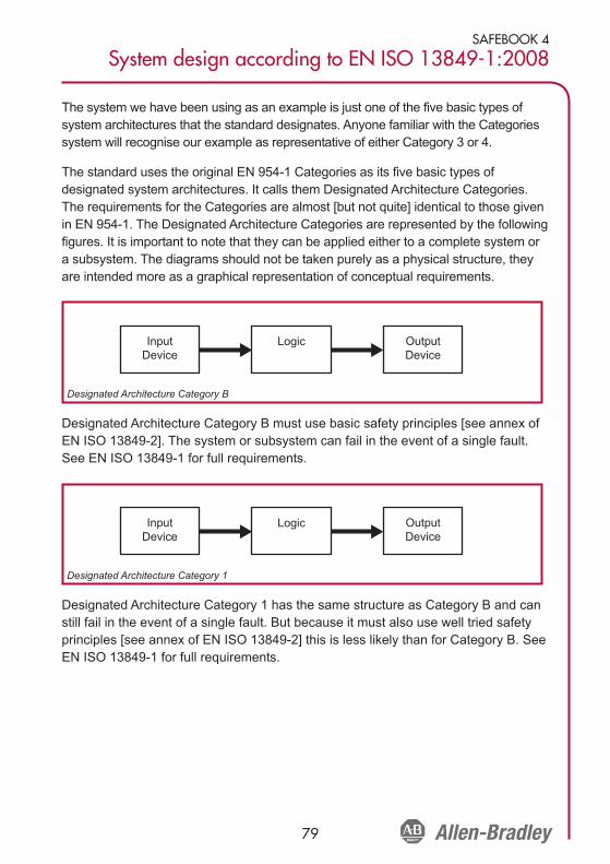
SAFEBOOK 4
System design according to EN ISO 13849-1:2008
79
The system we have been using as an example is just one of the five basic types ofsystem architectures that the standard designates. Anyone familiar with the Categoriessystem will recognise our example as representative of either Category 3 or 4.
The standard uses the original EN 954-1 Categories as its five basic types ofdesignated system architectures. It calls them Designated Architecture Categories.The requirements for the Categories are almost [but not quite] identical to those givenin EN 954-1. The Designated Architecture Categories are represented by the followingfigures. It is important to note that they can be applied either to a complete system ora subsystem. The diagrams should not be taken purely as a physical structure, theyare intended more as a graphical representation of conceptual requirements.
Designated Architecture Category B must use basic safety principles [see annex ofEN ISO 13849-2]. The system or subsystem can fail in the event of a single fault.See EN ISO 13849-1 for full requirements.
Designated Architecture Category 1 has the same structure as Category B and canstill fail in the event of a single fault. But because it must also use well tried safetyprinciples [see annex of EN ISO 13849-2] this is less likely than for Category B. SeeEN ISO 13849-1 for full requirements.
InputDevice
Logic OutputDevice
Designated Architecture Category 1
InputDevice
Logic OutputDevice
Designated Architecture Category B
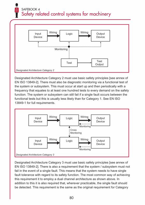
80
SAFEBOOK 4
Safety related control systems for machinery
Designated Architecture Category 2 must use basic safety principles [see annex ofEN ISO 13849-2]. There must also be diagnostic monitoring via a functional test ofthe system or subsystem. This must occur at start up and then periodically with afrequency that equates to at least one hundred tests to every demand on the safetyfunction. The system or subsystem can still fail if a single fault occurs between thefunctional tests but this is usually less likely than for Category 1. See EN ISO13849-1 for full requirements.
Designated Architecture Category 3 must use basic safety principles [see annex ofEN ISO 13849-2]. There is also a requirement that the system / subsystem must notfail in the event of a single fault. This means that the system needs to have singlefault tolerance with regard to its safety function. The most common way of achievingthis requirement it to employ a dual channel architecture as shown above. Inaddition to this it is also required that, wherever practicable, the single fault shouldbe detected. This requirement is the same as the original requirement for Category
InputDevice
Logic OutputDevice
Test
WiringWiring
TestOutput
Monitoring
Designated Architecture Category 2
InputDevice
Logic OutputDevice
Wiring
Monitoring
Monitoring
CrossMonitoring
Wiring
InputDevice
Logic OutputDevice
WiringWiring
Designated Architecture Category 3

SAFEBOOK 4
System design according to EN ISO 13849-1:2008
81
3 from EN 954-1. In that context the meaning of the phrase "wherever practicable"proved somewhat problematic. It meant that Category 3 could cover everything froma system with redundancy but no fault detection [often descriptively andappropriately termed "stupid redundancy"] to a redundant system where all singlefaults are detected. This issue is addressed in EN ISO 13849-1 by the requirementto estimate the quality of the Diagnostic Coverage [DC]. We can see that the greaterthe reliability [MTTFd] of the system, the less the DC we need. However it is alsoclear that the DC needs to be at least 60% for Category 3 Architecture.
Designated Architecture Category 4 must use basic safety principles [see annex ofEN ISO 13849-2]. It has a similar requirements diagram to Category 3 but itdemands greater monitoring i.e. higher Diagnostic Coverage. This is shown by theheavier dotted lines representing the monitoring functions. In essence the differencebetween Categories 3 and 4 is that for Category 3 most faults must be detected butfor Category 4 all single faults must be detected. The DC needs to be at least 99%.Even combinations of faults must not cause a dangerous failure.
Reliability Data
EN ISO 13849-1 uses quantitative reliability data as part of the calculation of the PLachieved by the safety related parts of a control system. This is a significantdeparture from EN 954-1. The first question this raises is "where do we get this datafrom?" It is possible to use data from recognised reliability handbooks but thestandard makes it clear that the preferred source is the manufacturer. To this end,Rockwell Automation is making the relevant information available in the form of adata library for SISTEMA. In due course it will also publish the data in other forms.Before we go any further we should consider what types of data are required andalso gain an understanding of how it is produced.
InputDevice
Logic OutputDevice
Wiring
Monitoring
Monitoring
CrossMonitoring
Wiring
InputDevice
Logic OutputDevice
WiringWiring
Designated Architecture Category 4

82
SAFEBOOK 4
Safety related control systems for machinery
The ultimate type of data required as part of the PL determination in the standard[and SISTEMA] is the PFH [the probability of dangerous failure per hour]. This is thesame data as represented by the PFHd abbreviation used in IEC/EN 62061.
The table above shows the relationship between PFH and PL and SIL. For somesubsystems the PFH may be available from the manufacturer. This makes life easierfor the calculation. The manufacturer will usually have to perform some relativelycomplex calculation and/or testing on their subsystem in order to provide it. In theevent that it is not available, EN ISO13849-1 gives us an alternative simplifiedapproach based on the average MTTFd [mean time to a dangerous failure] of asingle channel. The PL [and therefore the PFH] of a system or subsystem can thenbe calculated using the methodology and formulae in the standard. It can be doneeven more conveniently using SISTEMA.
NOTE: It is important to understand that, for a dual channel system (with or withoutdiagnostics), it is not correct to use 1/PFHD to determine the MTTFd that is requiredby EN ISO 13849-1. The standard calls for the MTTFd of a single channel. This is avery different value to the MTTFd of the combination of both channels of a twochannel subsystem. If the PFHD of a two channel subsystem is known, it can simplybe entered directly in to SISTEMA
MTTFd of a Single Channel
This represents the average mean time before the occurrence of a failure that couldlead to the failure of the safety function. It is expressed in years. It is an averagevalue of the MTTFd's of the "blocks" of each channel and can be applied to either asystem or a subsystem. The standard gives the following formula which is used tocalculate the average of all the MTTFd's of each element used in a single channelor subsystem.
PL(Performance Level)
PFHD
(Probability of dangerousfailure per hour)
SIL(Safety Integrity
Level)
a ≥10–5 to <10–4 None
b ≥3 x 10⁻⁶ to <10–5 1
c ≥10–6 to <3 x 10⁻⁶ 1
d ≥10–7 to <10–6 2
e ≥10–8 to <10–7 3

SAFEBOOK 4
System design according to EN ISO 13849-1:2008
83
At this stage the value of SISTEMA becomes apparent. Users are spared timeconsuming consultation of tables and calculation of formulae since these tasks areperformed by the software. The final results can be printed out in the form of amultiple page report.
(Formula D1 from EN ISO 13849-1)
In most dual channel systems both channel are identical therefore the result of theformula represents either channel.
If the system/subsystem channels are different the standard provides a formula tocater for this.
This, in effect, averages the two averages. In the cause of simplification it is alsoallowable to just use the worst case channel value.
The standard groups the MTTFd into three ranges as follows:-
Levels of MTTFd
Note that EN ISO 13849-1 limits the usable MTTFd of a single channel of asubsystem to a maximum of 100 years even though the actual values derived maybe much higher
As we will see later, the achieved range of MTTFd average is then combined withthe designated architecture Category and the diagnostic coverage [DC] to provide apreliminary PL rating. The term preliminary is used here because other requirementsincluding systematic integrity and measures against common cause failure still haveto be met where relevant.
Denotation of MTTFdof each channel Range of MTTFd of each channel
Low 3 years <= MTTFd < 10 years
Medium 10 years <= MTTFd < 30 years
High 30 years <= MTTFd < 100 years
=MTTF 32 1
d MTTF +MTTF+
dC1 dC2 1MTTFdC1
1MTTFdC2
1 Ñ
i=1= ΣMTTFd
1MTTFdi
Ñ
j=1= Σ nj
MTTFdj

84
SAFEBOOK 4
Safety related control systems for machinery
Methods of Data Determination
We now need to delve one stage deeper into how a manufacturer determines the dataeither in the form of PFHd or MTTFd. An understanding of this is essential whendealing with manufacturers data. Components can be grouped into three basic types:
• Mechanistic (Electro-mechanical, mechanical, pneumatic, hydraulic etc)• Electronic (i.e. solid state)• Software
There is a fundamental difference between the common failure mechanisms ofthese three technology types. In basic form it can be summarised as follows:-
Mechanistic Technology:
Failure is proportional to both the inherent reliability and the usage rate. Thegreater the usage rate, the more likely that one of the component parts may bedegraded and fail. Note that this is not the only failure cause, but unless we limitthe operation time/cycles it will be the predominant one. It is self evident that acontactor that has switching cycle of once per ten seconds will operate reliablyfor a far shorter time than an identical contactor that operates one per day.Physical technology devices generally comprise components that are individuallydesigned for their specific use. The components are shaped, molded, cast,machined etc. They are combined with linkages, springs, magnets, electricalwindings etc to form a mechanism. Because the component parts do not, ingeneral, have any history of use in other applications, we cannot find any pre-existing reliability data for them. The estimation of the PFHD or MTTFd for themechanism is normally based on testing. Both EN/IEC 62061 and EN ISO13849-1 advocate a test process known as B10d Testing.
In the B10d test a number of device samples [usually at least ten] are testedunder suitably representative conditions. The mean number of operating cyclesachieved before 10% of the samples fail to the dangerous condition is known asthe B10d value. In practice it is often the case that all of the samples will fail to asafe state but in that case the standard states that the B10d[dangerous] valuecan be taken as twice the B10[safe] value.
SAFEBOOK 4
System design according to EN ISO 13849-1:2008
85
Electronic Technology:
There are no physical wear related moving parts. Given an operating environmentcommensurate with the specified electrical and temperature [etc] characteristics,the predominant failure of an electronic circuit is proportional to the inherentreliability of its constituent components [or lack off it]. There are many reasons forindividual component failure; imperfection introduced during manufacture,excessive power surges, mechanical connection problems etc. In general, faults inelectronic components are difficult to predict by analysis and they appear to berandom in nature. Therefore testing of an electronic device in test laboratoryconditions will not necessarily reveal typical long term failure patterns.
In order to determine the reliability of electronic devices it is usual to useanalysis and calculation. We can find good data for the individual components inreliability data handbooks. We can use analysis to determine which componentfailure modes are dangerous. It is acceptable and usual to average out thecomponent failure modes as 50% safe and 50% dangerous. This normallyresults in relatively conservative data.
IEC 61508 provides formulae that can be used to calculate the overall probabilityof dangerous failure [PFH or PFD] of the device i.e. the subsystem. Theformulae are quite complex and take into account [where applicable] componentreliability, potential for common cause failure [beta factor], diagnostic coverage[DC], functional test interval and proof test interval. The good news is that thiscomplex calculation will normally be done by the device manufacturer. BothEN/IEC 62061 and EN ISO 13849-1 accept a subsystem calculated in this wayto IEC 61508. The resulting PFHD can be used directly into either Annex K ofEN ISO 13849-1 or the SISTEMA calculation tool.

86
SAFEBOOK 4
Safety related control systems for machinery
Software:
Failures of software are inherently systematic in nature. Any failures are causedby the way it is conceived, written or compiled. Therefore all failures are causedby the system under which it is produced, not by its use. Therefore in order tocontrol the failures we must control that system. Both IEC 61508 and EN ISO13849-1 provide requirements and methodologies for this. We do not need to gointo detail here other than to say they use the classic V model. Embeddedsoftware is an issue for the designer of the device. The usual approach is todevelop embedded software in accordance with the formal methods layed out inIEC 61508 part 3. When it comes to application code, the software that a userinterfaces with, most programmable safety devices are provided with "certified"function blocks or routines. This simplifies the validation task for application codebut it must be remembered that the completed application program still needs tobe validated. The way the blocks are linked and parameterised must be provedcorrect and valid for the intended task. EN ISO 13849-1 and IEC/EN 62061 Bothprovide guidelines for this process.
Result
VerificationCoding
Moduletesting
Moduledesign
Systemdesign
Integrationtesting
ValidationValidatedsoftware
Safetyfunctionsspecification
ValidationSafety-related
softwarespecification
V model for software development
SAFEBOOK 4
System design according to EN ISO 13849-1:2008
87
Diagnostic Coverage
We have already touched on this subject when we considered the DesignatedArchitecture Categories 2, 3 and 4. Those Categories require some form ofdiagnostic testing to check whether the safety function is still working. The term"diagnostic coverage" [usually abbreviated to DC] is used to characterise theeffectiveness of this testing. It is important to realise that DC is not based just onthe number of components that can fail dangerously. It takes account of the totaldangerous failure rate. The symbol λ is used for "failure rate". DC expresses therelationship of the rates of occurrence of the two following types of dangerousfailure;
Dangerous detected failure [λdd] i.e. Those failures that would cause, or couldlead to, a loss of the safety function, but which are detected. After detection, afault reaction function causes the device or system to go to safe state.
Dangerous failure [λd] i.e. All those failures that could potentially cause, or leadto, a loss of the safety function. This includes both the failures that are detectedand those that are not. Of course the failures that are truly dangerousare the dangerous undetected ones [termed λdu]
DC is expressed by the formula;
DC = λdd/λd expressed as a percentage.
This meaning of the term DC is common to EN ISO 13849-1 and EN/IEC 62061.However the way that it is derived differs. The latter standard proposes the use ofcalculation based on failure mode analysis but EN ISO 13849-1 provides asimplified method in the form of look-up tables. Various typical diagnostic techniquesare listed together with the DC percentage that their use is deemed to achieve. Insome cases rational judgment is still required, for example in some techniques theachieved DC is proportional to how often the test is performed. It is sometimesargued that this approach is too vague. However the estimation of DC can dependon many different variables and whichever technique is used the result can usuallyonly truly be described as approximate.

88
SAFEBOOK 4
Safety related control systems for machinery
It is also important to understand that the tables in EN ISO 13849-1 are based onextensive research conducted by the BGIA into the results achieved by knownactual diagnostic techniques used in real applications. In the interest of simplificationthe standard divides DC into four basic ranges.
<60% = none
60% to <90% = low
90% to <99% = medium
≥99% = high
This approach of dealing with ranges instead of individual percentage values alsocan be considered to be more realistic in terms of achievable accuracy. TheSISTEMA tool uses the same look-up tables as the standard. As the use of complexelectronics increases in safety related devices, DC becomes a more importantfactor. It is likely that future work on the standards will look further into clarification ofthis issue. In the meantime the use of engineering judgment and common senseshould be sufficient to lead to the correct choice of DC range.
Common Cause Failure
In most dual channel [i.e. single fault tolerant] systems or subsystems the diagnosticprinciple is based on the premise that there will not be dangerous failures of bothchannels at the same time. The term "at the same time" is more accuratelyexpressed as "within the diagnostic test interval". If the diagnostic test interval isreasonably short [e.g. less than eight hours] it is a reasonable assumption that twoseparate and unrelated faults are highly unlikely to occur within that time. Howeverthe standard makes it clear that we need to think carefully about whether the faultpossibilities really are separate and unrelated. For example, if a fault in onecomponent can foreseeably lead to failures of other components then the resultingtotality of faults are deemed to be a single failure.
It is also possible that an event that causes one component to fail may also causethe failure of other components. This is termed "common cause failure", normallyabbreviated as CCF. The degree of propensity for CCF is normally described as the
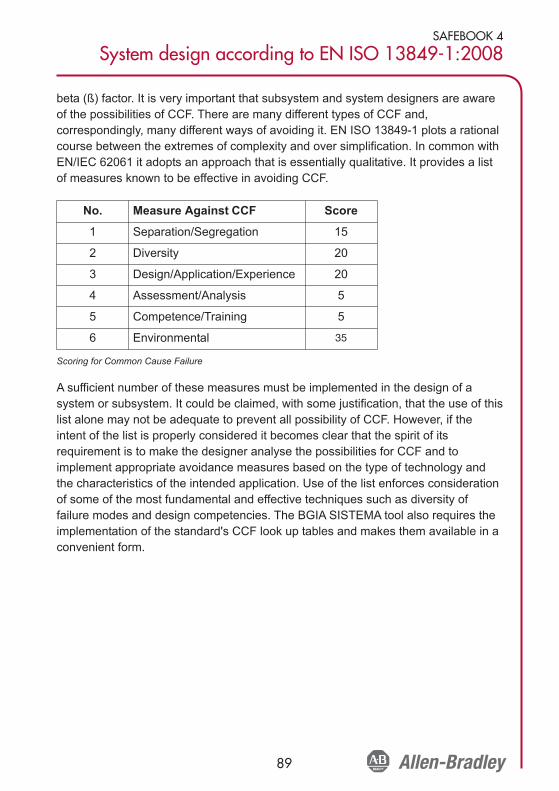
SAFEBOOK 4
System design according to EN ISO 13849-1:2008
89
beta (ß) factor. It is very important that subsystem and system designers are awareof the possibilities of CCF. There are many different types of CCF and,correspondingly, many different ways of avoiding it. EN ISO 13849-1 plots a rationalcourse between the extremes of complexity and over simplification. In common withEN/IEC 62061 it adopts an approach that is essentially qualitative. It provides a listof measures known to be effective in avoiding CCF.
Scoring for Common Cause Failure
A sufficient number of these measures must be implemented in the design of asystem or subsystem. It could be claimed, with some justification, that the use of thislist alone may not be adequate to prevent all possibility of CCF. However, if theintent of the list is properly considered it becomes clear that the spirit of itsrequirement is to make the designer analyse the possibilities for CCF and toimplement appropriate avoidance measures based on the type of technology andthe characteristics of the intended application. Use of the list enforces considerationof some of the most fundamental and effective techniques such as diversity offailure modes and design competencies. The BGIA SISTEMA tool also requires theimplementation of the standard's CCF look up tables and makes them available in aconvenient form.
No. Measure Against CCF Score
1 Separation/Segregation 15
2 Diversity 20
3 Design/Application/Experience 20
4 Assessment/Analysis 5
5 Competence/Training 5
6 Environmental 35

90
SAFEBOOK 4
Safety related control systems for machinery
Systematic Faults
We have already discussed quantified safety reliability data in the form of MTTFdand the probability of dangerous failure. However this is not the whole story. Whenwe referred to those terms we were really thinking about failures that appear to berandom in nature. Indeed IEC/EN 62061 specifically refers to the abbreviation ofPFHd as the probability of random hardware failure. But there are some types offailures collectively known as "systematic failure" that can be attributed to errorscommitted in the design or manufacturing process. The classic example of this is anerror in software code. The standard provides measures in Annex G to avoid theseerrors [and therefore the failures]. These measures include provisions such as theuse of suitable materials and manufacturing techniques, reviews, analysis andcomputer simulation. There are also foreseeable events and characteristics that canoccur in the operating environment that could cause failure unless their effect iscontrolled. Annex G also provides measures for this. For example it is easilyforeseeable that there may be occasional losses of power. Therefore the de-energisation of components must result in a safe state for the system. Thesemeasures may seem to be just common sense, and indeed they are, but they arenevertheless essential. All the rest of the requirements of the standard will bemeaningless unless due consideration is given to the control and avoidance ofsystematic failure. This will also sometimes require the same types of measuresused for the control of random hardware failure [in order to achieve the requiredPFHd] such as automatic diagnostic test and redundant hardware.
Fault Exclusion
One of the primary analysis tools for safety systems is failure analysis. The designerand user must understand how the safety system performs in the presence of faults.Many techniques are available to perform the analysis. Examples include Fault TreeAnalysis; Failure Modes, Effects and Criticality Analysis; Event Tree Analysis; andLoad-Strength reviews.
During the analysis, certain faults may be uncovered that cannot be detected withautomatic diagnostic testing without undue economic costs. Further, the probabilitythat these faults might occur may be made extremely small, by using mitigatingdesign, construction and test methods. Under these conditions, the faults may be

SAFEBOOK 4
System design according to EN ISO 13849-1:2008
91
excluded from further consideration. Fault exclusion is the ruling out of the occurrenceof a failure because the probability of that specific failure of the SRCS is negligible.
ISO13849-1:2006 allows fault exclusion based on the technical improbability ofoccurrence, generally accepted technical experience and the technical requirementsrelated to the application. ISO13849-2:2003 provides examples and justifications forexcluding certain faults for electrical, pneumatic, hydraulic and mechanical systems.Fault exclusions must be declared with detailed justifications provided in thetechnical documentation.
It is not always possible to evaluate Safety-related Control System without assumingthat certain faults can be excluded. For detailed information on fault exclusions, seeISO 13849-2.
As the level of risk gets higher, the justification for fault exclusion gets morestringent. In general, where PLe is required for a safety function to be implementedby a safety-related control system it is not normal to rely upon fault exclusions aloneto achieve this level of performance. This is dependent upon the technology usedand the intended operating environment. Therefore it is essential the designer takesadditional care on the use of fault exclusions as that PL requirement increases.
For example, a door interlocking system that has to achieve PLe will need toincorporate a minimum fault tolerance of 1 (e.g. two conventional mechanicalposition switches) in order to achieve this level of performance since it is notnormally justifiable to exclude faults, such as, broken switch actuators. However, itmay be acceptable to exclude faults, such as short circuits in wiring within a controlpanel designed in accordance with relevant standards
Performance Level (PL)
The performance level is a discrete level that specifies the ability of the safety-related parts of the control system to perform a safety function.
In order to assess the PL achieved by an implementation of any of the fivedesignated architectures, the following data is required for the system (orsubsystem):
• MTTFd (mean time to dangerous failure of each channel)• DC (diagnostic coverage).• Architecture (the category)

92
SAFEBOOK 4
Safety related control systems for machinery
The following diagram shows a graphical method for determining the PL from thecombination of these factors. The table at the end of this document shows thetabular results of different Markov models that created the basis of this diagram.Refer to the table when more precise determination is needed.
Other factors must also be realized to satisfy the required PL. These requirementsinclude the provisions for common cause failures, systematic failure, environmentalconditions and mission time.
If the PFHD of the system or subsystem is known, Table 10.4 (Annex K of thestandard) can be used to derive the PL.
Subsystem Design and Combinations
Subsystems that conform to a PL can be combined simply into a system using Table10.3. The rational behind this table is clear. First, that the system can only be asgood as its weakest subsystem. Second, the more subsystems there are, thegreater the possibility for failure.
Cat BDCavg none
Cat 1DCavg none
Cat 2DCavg low
Cat 2DCavg med
Cat 3DCavg low
Cat 3DCavg med
Cat 4DCavg high
a
d
e
c
b
Perfo
rman
ce L
evel
MTTFd lowMTTFd mediumMTTFd high Graphical determination of PL

SAFEBOOK 4
System design according to EN ISO 13849-1:2008
93
PL calculation for series combined subsystems
In the system shown in the followingdiagram, the lowest PerformanceLevels are at Subsystems 1 and 2.Both are PLb. Therefore, using thistable, we can read across b (in thePLlow column), through 2 (in the Nlow
column) and find the achieved systemPL as b (in the PL column). If all threesubsystems were PLb the achievedPL would be PLa.
Combination of series subsystems as a PLb system
Validation
Validation plays an important role throughout the safety system development andcommissioning process. ISO/EN 13849-2:2003 sets the requirements for validation.It calls for a validation plan and discusses validation by testing and analysistechniques such as Fault Tree Analysis and Failure Modes, Effects and CriticalityAnalysis. Most of these requirements will apply to the manufacturer of thesubsystem rather than the subsystem user.
Machine Commissioning
At the system or machine commissioning stage, validation of the safety functionsmust be carried out in all operating modes and should cover all normal andforeseeable abnormal conditions. Combinations of inputs and sequences ofoperation must also be taken into consideration. This procedure is importantbecause it is always necessary to check that the system is suitable for actualoperational and environmental characteristics. Some of those characteristics maybe different from the ones anticipated at the design stage.
Subsystem 2
PLb PLbSubsystem 1 Subsystem 3
PLc
PLlow Nlow PL
a>3 not allowed
≤3 a
b>2 a
≤2 b
c>2 b
≤2 c
d>3 c
≤3 d
e>3 d
≤3 e

94
SAFEBOOK 4
Safety related control systems for machinery
System Design According to IEC/EN 62061
IEC/EN 62061, ”Safety of machinery - Functional safety of safety related electrical,electronic and programmable electronic control systems,” is the machinery specificimplementation of IEC/EN 61508. It provides requirements that are applicable to thesystem level design of all types of machinery safety related electrical controlsystems and also for the design of non-complex subsystems or devices.
The risk assessment results in a risk reduction strategy which in turn, identifies theneed for safety related control functions. These functions must be documented andmust include a :
• functional requirements specification and a• safety integrity requirements specification.
The functional requirements include details like frequency of operation, requiredresponse time, operating modes, duty cycles, operating environment, and faultreaction functions. The safety integrity requirements are expressed in levels calledsafety integrity levels (SIL). Depending on the complexity of the system, some or allof the elements in the table below must be considered to determine whether thesystem design meets the required SIL.
Elements for SIL Consideration
Subsystems
The term “subsystem” has a special meaning in IEC/EN 62061. It is the first levelsubdivision of a system into parts which, if they fail, would cause a failure of the
Element for SIL Consideration Symbol
Probability of Dangerous Failure per Hour PFHD
Hardware Fault Tolerance No Symbol
Safe Failure Fraction SFF
Proof Test Interval T1
Diagnostic Test Interval T2
Susceptibility to Common Cause Failures ß
Diagnostic Coverage DC

SAFEBOOK 4
System Design According to IEC/EN 62061
95
safety function. Therefore if two redundant switches are used in a system neitherindividual switch is a subsystem. The subsystem would comprise both switches andany associated fault diagnostic function.
Probability of Dangerous Failure per Hour (PFHD)
IEC/EN 62061 uses the same basic methods as discussed in the section on EN ISO13849-1 to determine failure rates at the component level. The same provisions andmethods apply for “mechanistic” and electronic components. In IEC/EN 62061 thereis no consideration of MTTFd in years. The failure rate per hour (λ) is eithercalculated directly or obtained or derived from the B10 value by the followingformula:
λ = 0.1 x C/B10 (where C = the number of operating cycles per hour)
There is a significant difference between the standards in the methodology fordetermining the total PFHD for a subsystem or system. An analysis of thecomponents must be undertaken to determine the probability of failure of thesubsystems. Simplified formulae are provided for the calculation of commonsubsystem architectures (described later in text). Where these formulae are notappropriate it will be necessary to use more complex calculation methods such asMarkov models. The Probability of Dangerous Failure (PFHD) of each subsystem arethen added together to determine the total PFHD for the system. Table 15 (Table 3 ofthe standard) can then be used to determine which Safety Integrity Level (SIL) isappropriate to that range of PFHD.
λDssB = (1-ß)2 x λDe1 x λDe2 x T1 + ß x (λDe1 + λDe2) / 2
The formulae for this architecture take into account the parallel arrangement of thesubsystem elements and add the following two elements from the previous table:
ß (Beta) is the susceptibility to common cause failures
Probabilities of Dangerous Failure for SILs
SIL(Safety Integrity Level)
PFHD
(Probability of dangerous failure per hour)
3 ≥10–8 to <10–7
2 ≥10–7 to <10–6
1 ≥10–6 to <10–5

96
SAFEBOOK 4
Safety related control systems for machinery
The PFHD data for a subsystem will usually be provided by the manufacturer. Datafor Rockwell Automation safety components and systems is available in a number offorms including:
www.discoverrockwellautomation.com/safety
IEC/EN 62061 also makes it clear that reliability data handbooks can be used if andwhere applicable.
For low complexity electromechanical devices, the failure mechanism is usuallylinked to the number and frequency of operations rather than just time. Therefore forthese components the data will derived from some form of testing (e.g. B10 testingas described in the chapter on EN ISO 13849-1). Application based informationsuch as the anticipated number of operations per year is then required in order toconvert the B10d or similar data to PFHD.
NOTE: In general the following is true (taking into account a factor to change yearsto hours):
PFHD = 1/MTTFd
However, it is important to understand that, for a dual channel system (with orwithout diagnostics), it is not correct to use 1/ PFHD to determine the MTTFd that isrequired by EN ISO 13849-1. That standard calls for the MTTFd of a single channel.This is a very different value to the MTTFd of the combination of both channels of atwo channel subsystem
Architectural Constraints
The essential characteristic of IEC/EN 62061 is that the safety system is divided intosubsystems. The hardware safety integrity level that can be claimed for a subsystemis limited not only by the PFHD but also by the hardware fault tolerance and the safefailure fraction of the subsystems. Hardware fault tolerance is ability of the system toexecute its function in the presence of faults. A fault tolerance of zero means that thefunction is not performed when a single fault occurs. A fault tolerance of one allowsthe subsystem to perform its function in the presence of a single fault. Safe FailureFraction is the portion of the overall failure rate that does not result in a dangerousfailure. The combination of these two elements is known as the architecturalconstraint and its output is the SIL Claim Limit (SIL CL). The following table showsthe relationship of the architectural constraints to the SILCL. A subsystem (andtherefore its system) must satisfy both the PFHD requirements and the ArchitecturalConstraints together with the other relevant provisions of the standard.

SAFEBOOK 4
System Design According to IEC/EN 62061
97
Architectural Constraints on SIL
For example, a subsystem architecture that possesses single fault tolerance andhas a safe failure fraction of 75% is limited to no higher than a SIL2 rating,regardless of the probability of dangerous failure. When combining subsystems, theSIL achieved by the SRCS is constrained to be less than or equal to the lowest SILCL of any of the subsystems involved in the safety-related control function
System Realization
To compute the probability of dangerous failure, each safety function must bebroken down into function blocks, which are then realized as subsystems. A systemdesign implementation of a typical safety function would include a sensing deviceconnected to a logic device connected to an actuator. This creates a seriesarrangement of subsystems. As we have already seen, if we can determine theprobability of dangerous failure for each subsystem and know its SIL CL, then thesystem probability of failure is easily calculated by adding the probability of failuresof the subsystems. This concept is shown below.
SUBSYSTEM 1Position sensing
Functional and Integrity requirements from IEC/EN 62061
SIL CL 2 Architectural Constraints
PFHD = 1x10⁻⁷
SUBSYSTEM 3Output actuation
Functional and Integrity requirements from IEC/EN 62061
SIL CL 2 Architectural Constraints
PFHD = 1x10⁻⁷
SUBSYSTEM 2Logic solving
Functional and Integrity requirements from IEC/EN 62061
SIL CL 2 Architectural Constraints
PFHD = 1x10-7
= PFHD 1 = 1x10-7
= 3x10⁻⁷ i.e., suitable for SIL2
+ PFHD 2 + 1x10⁻⁷
+ PFHD 3 + 1x10⁻⁷
Safe FailureFraction
(SFF)
Hardware Fault Tolerance
0 1 2
<60%Not allowed unless specific
exceptions applySIL1 SIL2
60% - <90% SIL1 SIL2 SIL3
90% - < 99% SIL2 SIL3 SIL3
≥99% SIL3 SIL3 SIL3

98
SAFEBOOK 4
Safety related control systems for machinery
If, for example, we want to achieve SIL 2, each subsystem must have a SIL ClaimLimit (SIL CL) of at least SIL 2, and the sum of the PFHD for the system must notexceed the limit allowed in the previous table showing the ‘Probability of DangerousFailures for SILs’.
Subsystem Design – IEC/EN 62061
If a system designer uses components ready “packaged” into subsystems accordingto IEC/EN 62061 life becomes much easier because the specific requirements forthe design of subsystems do not apply. These requirements will, in general, becovered by the device (subsystem) manufacturer and are much more complex thanthose required for system level design.
IEC/EN 62061 requires that complex subsystems such as safety PLCs comply withIEC 61508 or other appropriate standards. This means that, for devices usingcomplex electronic or programmable components, the full rigor of IEC 61508applies. This can be a very rigorous and involved process. For example, theevaluation of the PFHD achieved by a complex subsystem can be a verycomplicated process using techniques such as Markov modeling, reliability blockdiagrams or fault tree analysis.
IEC/EN 62061 does give requirements for the design of lower complexitysubsystems. Typically this would include relatively simple electrical componentssuch as interlock switches and electromechanical safety monitoring relays. Therequirements are not as involved as those in IEC 61508 but can still be quitecomplicated.
IEC/EN 62061 supplies four subsystem logical architectures with accompanyingformulae that can be used to evaluate the PFHD achieved by a low complexitysubsystem. These architectures are purely logical representations and should not bethought of as physical architectures. The four subsystem logical architectures withaccompanying formulae are shown in the following four diagrams.
For a basic subsystem architecture shown below, the probabilities of dangerousfailures are simply added together.

SAFEBOOK 4
System Design According to IEC/EN 62061
99
Subsystem logical architecture A
λDssA= λDe1 + . . . + λDen
PFHDssA = λDssA x 1h
λ, Lambda is used to designate the failure rate. The units of the failure rate arefailures per hour. λD, Lambda sub D is the dangerous failure rate. λDssA, Lambda subDssA is the dangerous failure rate of subsystem A. Lambda sub DssA is the sum ofthe failure rates of the individual elements, e1, e2, e3, up to and including en. Theprobability of dangerous failure is multiplied by 1 hour to create the probability offailure within one hour.
The next diagram shows a single fault tolerant system without a diagnostic function.When the architecture includes single fault tolerance, the potential for commoncause failure exists and must be considered. The derivation of the common causefailure is briefly described later in this chapter.
Subsystem logical architecture B
λDssB = (1-ß)2 x λDe1 x λDe2 x T1 + ß x (λDe1 + λDe2) / 2PFHDssB = λDssB x 1h
The formulae for this architecture take into account the parallel arrangement of thesubsystem elements and add the following two elements from the previous table‘Elements for SIL Consideration’.
Subsystem A
Subsystemelement 1
De1
Subsystemelement n
Den
Subsystem B
Subsystemelement 1
De1 CommoncausefailureSubsystem
element 2
De2

100
SAFEBOOK 4
Safety related control systems for machinery
ß – the susceptibility to common cause failures (Beta)
T1 – the proof test interval or lifetime, whichever is smaller. The proof test isdesigned to detect faults and degradation of the safety subsystem so that thesubsystem can be restored to an operating condition. In practical terms this usuallymeans replacement (like the equivalent term “mission time” in EN ISO 13849-1).
The next diagram shows the functional representation of a zero fault tolerant systemwith a diagnostic function. Diagnostic coverage is used to decrease the probabilityof dangerous hardware failures. The diagnostic tests are performed automatically.The definition of diagnostic coverage is the same as given in EN ISO 13849-1 i.e.the ratio of the rate of detected dangerous failures compared to the rate of alldangerous failures.
Subsystem logical architecture C
λDssC = λDe1 (1-DC1)+ . . . + λDen (1-DCn)PFHDssC = λDssC x 1h
These formulae include the diagnostic coverage, DC, for each of the subsystemelements. The failure rates of each of the subsystems are reduced by the diagnosticcoverage of each subsystem.
The fourth example of a subsystem architecture is shown next. This subsystem issingle fault tolerant and includes a diagnostic function. The potential for commoncause failure must also be considered with single fault tolerant systems.
Subsystem C
Subsystemelement 1
De1
Diagnostic function(s)
Subsystemelement n
Den
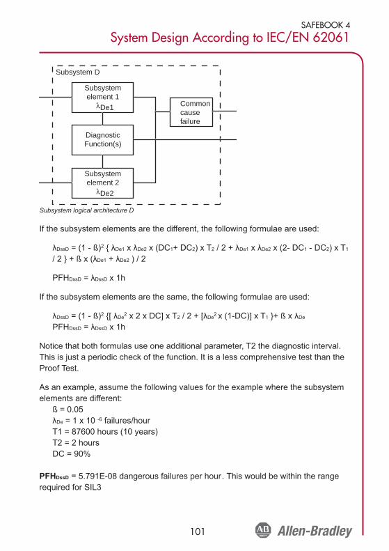
SAFEBOOK 4
System Design According to IEC/EN 62061
101
Subsystem logical architecture D
If the subsystem elements are the different, the following formulae are used:
λDssD = (1 - ß)2 { λDe1 x λDe2 x (DC1+ DC2) x T2 / 2 + λDe1 x λDe2 x (2- DC1 - DC2) x T1
/ 2 } + ß x (λDe1 + λDe2 ) / 2
PFHDssD = λDssD x 1h
If the subsystem elements are the same, the following formulae are used:
λDssD = (1 - ß)2 {[ λDe2 x 2 x DC] x T2 / 2 + [λDe2 x (1-DC)] x T1 }+ ß x λDe
PFHDssD = λDssD x 1h
Notice that both formulas use one additional parameter, T2 the diagnostic interval.This is just a periodic check of the function. It is a less comprehensive test than theProof Test.
As an example, assume the following values for the example where the subsystemelements are different:
ß = 0.05λDe = 1 x 10 -6 failures/hourT1 = 87600 hours (10 years)T2 = 2 hoursDC = 90%
PFHDssD = 5.791E-08 dangerous failures per hour. This would be within the rangerequired for SIL3
Subsystem D
Subsystemelement 1
λDe1 Commoncausefailure
DiagnosticFunction(s)
Subsystemelement 2
λDe2

102
SAFEBOOK 4
Safety related control systems for machinery
Affect of the Proof Test Interval
IEC/EN 62061 states that a Proof Test Interval (PTI) of 20 years is preferred (but notmandatory) Let us look at the affect the proof test interval has on the system. If we re-calculate the formula with T1 at 20 years it gives the result PFHDssD = 6.581E-08. It isstill within the range required for SIL 3. The designer must keep in mind that thissubsystem must be combined with other subsystems to calculate the overall dangerousfailure rate.
Affect of Common Cause Failure Analysis
Let’s look at the affect the common cause failures have on the system. Suppose wetake additional measures and our ß (Beta) value improves to 1% (0,01), while theproof test interval remains at 20 years. The dangerous failure rate improves to2.71E-08 which means that the subsystem is now more suitable for use in a SIL 3system.
Common Cause Failure (CCF)
Common cause failure is when multiple faults resulting from a single cause producea dangerous failure. Information on CCF will generally only be required by thesubsystem designer, usually the manufacturer. It is used as part of the formulaegiven for estimation of the PFHD of a subsystem. It will not usually be required atthe system design level.
Annex F of IEC/EN62061 provides a simple approach for the estimation of CCF. Thetable below shows a summary of the scoring process
Scoring for Measures Against Common Cause Failure
Points are awarded for employing specific measures against CCF. The score is addedup to determine the common cause failure factor, which is shown in the followingtable. The beta factor is used in the subsystem models to “adjust” the failure rate.
No. Measure Against CCF Score
1 Separation/Segregation 25
2 Diversity 38
3 Design/Application/Experience 2
4 Assessment/Analysis 18
5 Competence/Training 4
6 Environmental 18

SAFEBOOK 4
System Design According to IEC/EN 62061
103
Beta Factor for Common Cause Failure
Diagnostic Coverage (DC)
Automatic diagnostic tests are employed to decrease the probability of dangeroushardware failures. Being able to detect all dangerous hardware failures would beideal, but in practice the maximum value is set at 99% (this can also be expressedas 0.99)
Diagnostic coverage is the ratio of the probability of detected dangerous failures tothe probability all the dangerous failures.
Probability of Detected dangerous failures, λDD
DC = ---------------------------------------------------------------Probability of Total dangerous failures, λDtotal
The value of diagnostic coverage will lie between zero and one.
Hardware Fault Tolerance
Hardware fault tolerance represents the number of faults that can be sustained by asubsystem before it causes a dangerous failure. For example, a hardware faulttolerance of 1 means that 2 faults could cause a loss of the safety related controlfunction but one fault would not.
Management of Functional Safety
The standard gives requirements for the control of management and technicalactivities that are necessary for the achievement of a safety related electrical controlsystem.
Overall Score Common Cause failure factor (ß)
<35 10% (0,1)
35 - 65 5% (0,05)
65 - 85 2% (0,02)
85 - 100 1% (0.01)

104
SAFEBOOK 4
Safety related control systems for machinery
Proof Test Interval
The proof test interval represents the time after which a subsystem must be eithertotally checked or replaced to ensure that it is in an “as new” condition. In practice, inthe machinery sector, this is achieved by replacement. So the proof test interval ususually the same as lifetime. EN ISO 13849-1:2008 refers to this as Mission Time.
A proof test is a check that can detect faults and degradation in a SRCS so that theSRCS can be restored as close as practical to an “as new” condition”. The proof testmust detect 100% of all dangerous failures. Separate channels must be testedseparately.
In contrast to diagnostic tests, which are automatic, proof tests are usuallyperformed manually and off line. Being automatic, diagnostic testing is performedoften as compared to proof testing which is done infrequently. For example, thecircuits going to an interlock switch on a guard can be tested automatically for shortand open circuit conditions with diagnostic (e.g., pulse) testing.
The proof test interval must be declared by the manufacturer. Sometimes themanufacturer will provide a range of different proof test intervals.
Safe Failure Fraction (SFF)
The safe failure fraction is similar to diagnostic coverage but also takes account ofany inherent tendency to fail towards a safe state. For example, when a fuse blows,there is a failure but it is highly probable that the failure will be to an open circuitwhich, in most cases, would be a “safe” failure. SFF is (the sum of the rate of “safe”failures plus the rate of detected dangerous failures) divided by (the sum of the rateof “safe” failures plus the rate of detected and undetected dangerous failures). It isimportant to realize that the only types of failures to be considered are those whichcould have some affect on the safety function.
Most low complexity mechanical devices such as E-stop buttons and interlockswitches will (on their own)have an SFF. Most electronic devices for safety havedesigned in redundancy and monitoring therefore an SFF of greater than 90% iscommon although this is usually completely due to the Diagnostic Coveragecapability. The SFF value will normally be supplied by the manufacturer.

SAFEBOOK 4
System Design According to IEC/EN 62061
105
The Safe Failure Fraction (SFF) can be calculated using the following equation:
SFF = (Σλ S + Σλ DD) / (Σλ S + Σλ D)where
λ S = the rate of safe failure,Σλ S + Σλ D = the overall failure rate,λ DD = the rate of detected dangerous failure λ D = the rate of dangerous failure.
Systematic Failure
The standard has requirements for the control and avoidance of systematic failure.Systematic failures differ from random hardware failures which are failures occurringat a random time, typically resulting from degradation of parts of hardware. Typicaltypes of possible systematic failure are software design errors, hardware designerrors, requirement specification errors and operational procedures. Examples ofsteps necessary to avoid systematic failure include
• proper selection, combination, arrangements, assembly and installation ofcomponents,
• use of good engineering practice;• follow manufacturer’s specifications and installation instructions;• ensuring compatibility between components• withstanding environmental conditions: • use of suitable materials

106
SAFEBOOK 4
Safety related control systems for machinery
Safety-Related Control System Structure Considerations
Overview
This chapter looks at general structural considerations and principles that should betaken into account when designing a safety related control system to any standard.It uses much of language of the Categories from the outgoing EN 954-1 becausethe Categories primarily address the structure of control systems.
Categories of Control Systems
The “Categories” of control systems originated in the outgoing EN 954-1:1996(ISO13849-1:1999). However they are still often used to describe safety controlsystems and they remain an integral part of EN ISO13849-1 as discussed in“Introduction to Functional Safety of Control Systems” section.
There are five categories describing the fault reaction performance of a safetyrelated control system. See Table 19 for a summary of these categories. Thefollowing notes apply to the table.
Note 1: Category B in itself has no special measures for safety but it forms thebase for the other categories.
Note 2: Multiple faults caused by a common cause or as inevitableconsequences of the first fault shall be counted as a single fault.
Note 3: The fault review may be limited to two faults in combination if it can bejustified but complex circuits (e.g. microprocessor circuits) may require morefaults in combination to be considered.
Category 1 is aimed at the prevention of faults. It is achieved through the use ofsuitable design principles, components and materials. Simplicity of principle anddesign together with stable and predictable material characteristics are the keys tothis category.
Categories 2, 3 and 4 require that if faults cannot be prevented they must bedetected and appropriate action taken.
Redundancy, diversity and monitoring are the keys to these categories. Redundancyis the duplication of the same technique. Diversity is using two different techniques.Monitoring is the checking the status of devices and then taking appropriate actionbased on results of the status. The usual, but not only, method of monitoring is toduplicate the safety critical functions and compare operation.

SAFEBOOK 4
Safety Related Control System Structure Considerations
107
Summary of Requirements System Behaviour
Category B (see Note 1)Safety related parts of machine control systems and/ortheir protective equipment, as well as theircomponents, shall be designed, constructed, selected,assembled and combined in accordance with relevantstandards so that they can withstand the expectedinfluence. Basic safety principles shall be applied
When a fault occurs, it can lead to aloss of the safety function
CATEGORY 1The requirements of category B apply together withthe use of well tried safety components and safetyprinciples.
As described for category B but withhigher safety related reliability of thesafety related function. (The higher thereliability, the less the likelihood of a fault).
CATEGORY 2The requirements of category B and the use of welltried safety principles apply. The safety function(s) shallbe checked at machine start-up and periodically by themachine control system. If a fault is detected a safestate shall be initiated or if this is not possible a warningshall be given. EN ISO 13849-1 assumes that the testrate is at least 100 times more frequent that thedemand rate. EN ISO 13849-1 assumes that theMTTFd of the external test equipment is larger than halfof the MTTFd of the functional equipment being tested.
The loss of safety function is detectedby the check. The occurrence of a faultcan lead to the loss of safety functionbetween the checking intervals.
CATEGORY 3 (see Notes 2 & 3)The requirements of category B and the use of welltried safety principles apply. The system shall bedesigned so that a single fault in any of its parts doesnot lead to the loss of safety function. Wherepracticable, a single fault shall be detected.
When the single fault occurs the safetyfunction is always performed. Some butnot all faults will be detected. Anaccumulation of undetected faults canlead to the loss of safety function.
Category 4 (see Notes 2 & 3)The requirements of category B and the use of well triedsafety principles apply. The system shall be designed sothat a single fault in any of its parts does not lead to theloss of safety function.The single fault is detected at orbefore the next demand on the safety function. If thisdetection is not possible then an accumulation of faultsshall not lead to a loss of safety function.
When the faults occur, the safetyfunction is always performed. The faultswill be detected in time to prevent theloss of safety functions.

108
SAFEBOOK 4
Safety related control systems for machinery
Category B
Category B provides the basic requirements of any control system; whether it is asafety related control system or non-safety related. A control system must work in itsexpected environment. The concept of reliability provides a foundation for controlsystems, as reliability is defined as the probability that a device will perform itsintended function for a specified interval under expected conditions.
Category B requires the application of basic safety principles. ISO 13849-2 tells us thebasic safety principles for electrical, pneumatic, hydraulic and mechanical systems.The electrical principles are summarized as follows:
• Proper selection, combination, arrangements, assembly and installation (i.e.,per mfg’rs instructions)
• Compatibility of components with voltages and currents• Withstand environmental conditions• Use of de-energization principle• Transient suppression• Reduction of response time• Protection against unexpected start-up• Secure fixing of input devices (e.g. mounting of interlocks)• Protection of control circuit (per NFPA79 & IEC60204-1)• Correct protective bonding
The designer must select, install, and assemble according to the manufacturer’sinstructions. These devices must work within the expected voltage and currentratings. The expected environmental conditions, like electromagnetic compatibility,vibration, shock, contamination, washdown, must also be considered. Thedeenergization principle is used. Transient protection is installed across thecontactor coils. The motor is protected against overloads. The wiring and groundingmeets the appropriate electrical standards.
Category 1
Category 1 requires the system to meet the terms of Category B and to use well-tried safety components. What exactly are safety components, and how do we knowwhether they are well-tried? ISO 13849-2 helps answer those questions formechanical, hydraulic, pneumatic and electrical systems. Annex D addresseselectrical components.

SAFEBOOK 4
Safety Related Control System Structure Considerations
109
Components are considered to be well–tried if they have been successfully used inmany similar applications. Newly designed safety components are considered to bewell-tried if they are designed and verified in compliance to appropriate standards.
Well-Tried Component Standard
Switch with positive mode actuation(direct opening action)
IEC 60947-5-1
Emergency stop device ISO 13850, IEC60947-5-5
Fuse IEC 60269-1
Circuit Breake IEC 60947-2
Contactors IEC 60947-4-1, IEC 60947-5-1
Mechanically linked contacts IEC 60947-5-1
Auxiliary contactor (e. g. contactor,control relay, positive guided relays)
EN 50205IEC 60204–1, IEC 60947–5–1
Transformer IEC 60742
Cable IEC 60204-1
Interlocks ISO 14119
Temperature Switch IEC 60947-5-1
Pressure SwitchIEC 60947-5-1 + pneumatic orhydraulic requirements
Control and protective switching deviceor equipment (CPS)
IEC 60947-6-2
Programmable Logic Controller IEC 61508, IEC 62061

110
SAFEBOOK 4
Safety related control systems for machinery
Applying well tried components to our Category B system, the limit switch would bereplaced by a direct opening action tongue switch and the contactor would be over-dimensioned to further protect against welded contacts.
Shown here is thechanges to thesimple Category Bsystem to achieveCategory 1. Theinterlock and thecontactor play thekey roles inremoving energyfrom the actuator,when access to thehazard is needed.The tongue interlockmeets therequirements of IEC
60947-5-1 for direct opening action contacts, which is shown by the symbol of thearrow within the circle. With the well-tried components, the probability of energybeing removed is higher for Category 1 than it is for Category B. The use of well-tried components is intended to prevent a loss of the safety function. Even withthese improvements, a single fault can still lead to the loss of the safety function.
Categories B and 1 are prevention based. The design is intended to prevent ahazardous situation. When prevention by itself does not provide enough reductionin the risk, fault detection must be used. Categories 2, 3 and 4 are fault detectionbased, with increasingly stringent requirements to achieve higher levels of riskreduction
Start
K1
GuardClosed
ContactorTS
TongueSwitch
K1Aux
Motor(Hazard)
K1
L1 L2 L3
Stop
OP
+VSCP
SCP
Gnd
Simple Category 1 Safety System

SAFEBOOK 4
Safety Related Control System Structure Considerations
111
Category 2
In addition to meeting the requirements of Category B and using well tried safetyprinciples, the safety system must undergo testing to meet Category 2. The testsmust be designed to detect faults within the safety related parts of the controlsystem. If faults are not detected, the machine is allowed to run. If faults aredetected, the test must initiate a command. Whenever possible, the command mustbring the machine to a safe state.
The test must provide reasonably practical detection of faults. The equipmentperforming the test can be an integral part of the safety system or a separate pieceof equipment.
The testing must be performed:• when the machine is initially powered,• prior to the initiation of a hazard, and.• periodically if deemed necessary by the risk assessment
Note: EN ISO 138491-1 assumes a test to safety function demand ration of 100:1.The example given here would not meet that requirement
The words “whenever possible” and “reasonably practicable” indicate that not allfaults are detectable. Since this is a single channel system (i.e., one wire connectsinput to logic to output), a single fault may lead to the loss of the safety function. Insome cases, Category 2 cannot be fully applied to a safety system, because not allof the components can be checked.
Input Logic
Test
OutputWiringWiring
TestOutput
Reasonably PracticalFault Detection

112
SAFEBOOK 4
Safety related control systems for machinery
Shown here is a simple Category 1 system enhanced to meet Category 2. Amonitoring safety relay (MSR) performs the testing. Upon power-up, the MSRchecks its internal components. If no faults are detected, the MSR checks thetongue switch by monitoring the cycling of its contacts. If no faults are detected andthe guard is closed, the MSR then checks the output device: the mechanically linkedcontacts of the contactor. If no faults are detected and the contactor is off, the MSRwill energize its internal output and connect the coil of K1 to the Stop button. At thispoint, the non safety rated parts of the machine control system, theStart/Stop/Interlock circuit, can turn the machine on and off.
Opening the guard turns the outputs of the MSR off. When the guard is re-closed,the MSR repeats the safety system checks. If no faults are discovered, the MSRturn on is internal output. The MSR allows this circuit to meet Category 2 byperforming tests on the input device, the logic device (itself) and the output device.The test is performed on initial power-up and before initiation of the hazard.
With its inherent logic capabilities, a PLC based safety system can be designed tomeet category 2. As stated in the Category 1 discussion above, the well-triedjustification of the PLC (including its testing capabilities) becomes the challenge. Forcomplex safety systems requiring a Category 2 rating, a PLC safety-rated to IEC61508 should be substituted for the non-safety rated PLC.
Start
K1
GuardClosed
TongueSwitch
K1Aux
Motor(Hazard)
K1
SCP
SCP
TS
OP
L1 L2 L3
Stop
+V
Gnd
MonitoringSafetyRelay
Contactor
Category 2 Safety System

SAFEBOOK 4
Safety Related Control System Structure Considerations
113
Shown here is anexample of acomplex systemusing a safety ratedPLC. A safety ratedPLC meets therequirements of well-tried as is designedto an appropriatestandard. Themechanically linkedcontacts of thecontactors are fed
into the Input of the PLC for testing purposes. These contacts may be connected inseries to one input terminal or to individual input terminals, depending on theprogram logic.
Although well-tried safety components are used, a single fault occurring betweenthe checks can lead to the loss of the safety function. Therefore, Category 2systems are used in lower risk applications. When higher levels of fault toleranceare needed, the safety system must meet Categories 3 or 4.
Category 3
In addition to meeting the requirements of Category B and well-tried safetyprinciples, Category 3 requires successful performance of the safety function in thepresence of a single fault. The fault must be detected at or before the next demandon the safety function, whenever reasonably practicable.
Here again we have the phrase “whenever reasonably practical”. This covers thosefaults that may not be detected. As long as the undetectable fault does not lead to theloss of the safety function, the safety function can meet category 3. Consequently, anaccumulation of undetected faults can lead to the loss of the safety function.
Here is a block diagram to explainthe principles of a Category 3system. Redundancy combinedwith reasonably practical crossmonitoring and output monitoringare used to ensure theperformance of the safety function
Input Logic Output
Wiring
Wiring
Input Logic OutputWiringWiring
Reasonably PracticalFault Detection
OutputLogicInput
Start
+V
Gnd
SCP SCP
Stop
SW1
SW2
SW3
K3
K2K1
K1
K2
K3
Safety Rated
TS
TS
TS
Complex Category 2 Safety System

114
SAFEBOOK 4
Safety related control systems for machinery
Shown here is an example of a Category 3 system. A redundant set of contacts areadded to the tongue interlock switch. Internally, the monitoring safety relay (MSR)contains redundant circuits that cross monitor each other. A redundant set ofcontactors remove power from the motor. The contactors are monitored by the MSRthrough the “reasonably practicable” mechanically linked contacts.
Fault detection must be considered for each part of the safety system, as well as theconnections (i.e., the system). What are the failure modes of a dual channel tongueswitch? What are the failure modes of the MSR? What are the failure modes of thecontactors K1 and K2? What are the failure modes of the wiring?
The tongue interlock switch is designed with direct opening contacts. Therefore weknow that opening the guard is designed to open a welded contact. This resolvesone failure mode. Do other failure modes exist?
The direct opening action switch is usually designed with a spring operate return. Ifthe head is removed or broken off, the safety contacts spring back to the closed(safe) state. Many interlock switches are designed with removable heads toaccommodate installation requirements of various applications. The head can beremoved and rotated between two to four positions.
A failure could occur where the head mounting screws are not torqued properly.With this condition, the expected vibration of the machine may cause the headmounting screws to back out. The operating head, under spring pressure, removes
Start
K1
GuardClosed Tongue
Switch
K2Aux
K1Aux
Motor(Hazard)
K2
K1
L1 L2 L3
Stop
K2
+V
ContactorsGnd
MonitoringSafetyRelay
SCP
SCP
OP
Ch1
Ch1
Ch2
Ch2
TS TS
Category 3 Safety System

SAFEBOOK 4
Safety Related Control System Structure Considerations
115
the pressure from the safety contacts, and the safety contacts close. Subsequently,opening the guard does not open the safety contacts, and a failure to dangeroccurs.
Similarly, the operating mechanism within the switch must be reviewed. What is theprobability that a failure of a single component will lead to the loss of the safetyfunction? A common practice is to use tongue interlocks with dual contacts inCategory 3 circuits. This usage must be based on excluding the single failure of theswitch to open the safety contacts. This is considered “fault exclusion” and isdiscussed later in this chapter.
A monitoring safety relay (MSR) is often evaluated by a third party and assigned acategory level (and/or a PL and SIL CL). The MSR often includes dual channelcapability, cross channel monitoring, external device monitoring and short circuitprotection. No specific standards are written to provide guidance on the design orusage of monitoring safety relays. MSRs are evaluated for their ability to perform thesafety function per EN ISO 13849-1 or the outgoing EN 954-1. The rating of theMSR must be the same or higher than the required rating of the system in which it isused.
Two contactors help to ensure that the safety function is fulfilled by the outputdevices. With overload and short-circuit protection, the probability of the contactorfailing with welded contacts is small but not impossible. A contactor can also fail duewith its power switching contacts staying closed due to a stuck armature. If onecontactor fails to a dangerous state, the second contactor will remove power fromthe hazard. The MSR will detect the faulted contactor upon the next machine cycle.When the gate is closed and the start button pressed, the mechanically linkedcontacts of the faulted contactor will remain open and the MSR will not be able toclose its safety contacts, thereby, revealing the fault
Undetected Faults
With a Category 3 system structure there may be some faults that cannot bedetected but they must not, by themselves, lead to the loss of the safety function.
Where faults can be detected we need to know if, under some circumstances, theycould be either masked or unintentionally cleared by the operation other deviceswithin the system structure.

116
SAFEBOOK 4
Safety related control systems for machinery
Shown here is a widely used approach for connecting multiple devices to amonitoring safety relay. Each device contains two normally closed direct openingaction contacts. These devices can be a mix of interlocks or e-stop buttons. Thisapproach saves wiring costs as the input devices are daisy-chained. Assume a shortcircuit fault occurs across one of the contacts at Sw2 as shown. Can this fault bedetected?
If switch Sw1 (or Sw3) is opened, both Ch1 and Ch2 are open circuit and the MSRremoves power from the hazard. If Sw3 is then opened and then closed again thefault across its contacts will not be detected because there is no change of status atthe MSR: both Ch1 and Ch2 remain open. If Sw1 (or Sw3) is then closed, thehazard can be restarted by pressing the start button. Under these circumstances thefault did not cause a loss of the safety function but it was not detected, it remains inthe system and a subsequent fault (a short circuit across the second contact ofSw2) could lead to the loss of the safety function.
Start
K1
K2Aux
K1Aux
Motor(Hazard)
K2
K1
SCP L1 L2 L3
Stop
K2
+V
Gnd
MonitoringSafetyRelay
Contactors
SCP
OP
Ch1
Ch1
Ch2
Ch2Sw1 Sw2 Sw3
Wiring Fault inthe System
TS TS
Series Connection of Input Devices

SAFEBOOK 4
Safety Related Control System Structure Considerations
117
If Sw2 alone was opened and closed, with no operation of the other switches, Ch1opens and Ch2 remains closed. The MSR deenergizes the hazard because Ch1opened. When Sw2 closes, the motor cannot be started when the Start button ispressed, because Ch2 did not open. The fault is detected. However if for anyreason, Sw1 (or Sw3) is then opened and closed, both Ch1 and Ch2 will be openthen closed circuit. This sequence simulates the clearing of the fault and will resultin unintentional reset at the MSR.
This raises the question of what DC could be claimed for the individual switcheswithin this structure when using EN ISO 13849-1 or IEC 62061. At the time ofpublication of this text there is no specific definitive guidance on this but it is usualand reasonable to assume a DC of 60% under the condition that the switches areindividually tested at suitable periods to reveal faults. If it is foreseeable that one (ormore) of the switches will never be individually tested then it can be argued that itsDC should be described as zero. At the time of publication of this text EN ISO13849-2 is undergoing revision. When it is published it may provide more guidanceon this issue.
The series connection of mechanical contacts is limited to Category 3 as it may leadto the loss of the safety function due to an accumulation of faults. In practical terms,the reduction of the DC (and therefore SFF) would limit the maximum achievable PLand SIL to PLd and SIL2.
It is interesting to note that these characteristics of a Category 3 structure havealways required consideration but they are brought into sharp focus by the newerfunctional safety standards.

118
SAFEBOOK 4
Safety related control systems for machinery
Shown here a category 3 circuit using a safety rated variable frequency drive.Developments in drive technology coupled with the updating of EN/IEC 60204-1 andNFPA79 standards allow safety rated drives to be used in e-stop circuits without theneed for an electro-mechanical disconnect of the actuator (e.g., the motor).
Pressing the E-Stop opens the outputs of the MSR. This sends a stop signal to thedrive, removes the enable signal and opens the gate control power. The driveexecutes a Category 0 Stop— immediate removal of power to the motor. Thisfunction is termed “Safe Torque Off.” The drive achieves category 3 because it hasredundant signals to remove power to the motor: the enable and a positive guidedrelay. The positive guided relay provides reasonably practicable feedback to theactuator. The drive itself is analyzed to determine that a single fault does not lead tothe loss of the safety function.
+V
Gnd
MonitoringSafetyRelay
Ch1
Ch1
Ch2
Ch2
SCP
E-Stop
Stop
Start
Motor(Hazard)
L1 L2 L3
Enable
24VDC
Safety RatedVariable Frequency
Drive
Comm GateControlCircuit
Gate ControlPower
Safety Rated Drives with E-stop Rated to Category 3

SAFEBOOK 4
Safety Related Control System Structure Considerations
119
Shown here is an example of a wiring fault, a short circuit, from the MSR Channel 2safety output to the coil of Contactor K1. All components are operating properly. Thiswiring fault can occur prior to machine commissioning or at some later date duringmaintenance or enhancements.
Can this fault be detected?
This fault cannot be detected by the safety system as shown. Fortunately it doesnot, on its own, lead to the loss of the safety function. This fault, as well as the faultfrom Ch1 to K2, must be detected during commissioning or checks followingmaintenance work. The list of possible fault exclusions given in EN ISO 13849-2Annex D Table D4 clarifies that these types of faults can be excluded if theequipment is contained within an electrical enclosure and both the enclosure andwiring comply with the requirements of IEC/EN 60204-1. The Joint Technical reporton EN ISO 13849-1 and IEC 62061 also clarifies that this fault exclusion can beconsidered up to and including PLe and SIL3. It can also be used at Category 4.
Start
K1
GuardClosed Tongue
Switch
K2Aux
K1Aux
Motor(Hazard)
K2
K1
L1 L2 L3
Stop
K2
+V
ContactorsGnd
MonitoringSafetyRelay
Wiring Fault inthe System
SCP
SCP
OP
Ch1
Ch1
Ch2
Ch2
TS TS
Example of a wiring fault

120
SAFEBOOK 4
Safety related control systems for machinery
Shown here is an example safety system with light curtains (OSSD outputs)
Can the safety system detect this fault?
The MSR cannot detect this fault, because both inputs are pulled up to +V. In thisexample, the wiring fault is detected by the light curtain. Some light curtains use afault detection technique called pulse testing. With these light curtains, the detectionof the fault is immediate, and the light curtain turns off its output. In others, thedetection is made when the light curtain is cleared. When the light curtain attemptsto energize its output, the fault is detected and the output remains off. In either case,the hazard remains off in the presence of the fault.
Pulse Testing Fault Detection
Safety circuits are designed to be carrying current when the safety system is activeand the hazard is protected. Pulse testing is a technique where the circuit currentdrops to zero for a very short duration. The duration is too short for the safety circuitto respond and turn the hazard off, but is long enough for a microprocessor basedsystem to detect. The pulses on the channels are offset from each other. If acrossfault short circuit occurs, the microprocessor detects the pulses on bothchannels and initiates a command to turn the hazard off.
Start
K1
K2Aux
K1Aux
Motor(Hazard)
K2
K1
L1 L2 L3
Stop
K2
+V
Gnd
MonitoringSafetyRelay
Contactors
SCP
OP
Ch1
Ch2
One Cross Channel WiringFault in the System
Sender Receiver
OSSD2
OSSD1
SCP
TS TS
Cross Channel Wiring Fault with Light Curtains

SAFEBOOK 4
Safety Related Control System Structure Considerations
121
Category 4
Like Category 3, Category 4 requires the safety system to meet Category B, usesafety principles and perform the safety function in the presence of a single fault.Unlike Category 3 where an accumulation of faults can lead to the loss of the safetyfunction, Category 4 requires performance of the safety function in the presence ofan accumulation of faults. When considering an accumulation of faults, 2 faults maybe sufficient, although 3 faults may me necessary for some designs.
Shown here is the blockdiagram for category 4.Monitoring of both outputdevices and cross monitoringis essentially required, not justwhen reasonably practicable.This helps differentiateCategory 4 from Category 3.
Shown here is an example Category 4 circuit using fault exclusion on the tongueinterlock. Fault exclusion eliminates consideration of the failure of the tongueinterlock contacts to open. Fault exclusion must be technically justified anddocumented. Actuator speed, actuator alignment, mechanical stops, and a securedoperating head must be considered in the justification.
Start
K1
GuardClosed Tongue
Switch
K2Aux
K1Aux
Motor(Hazard)
K2
K1
L1 L2 L3
Stop
K2
+V
ContactorsGnd
MonitoringSafetyRelay
SCP
SCP
OP
Ch1
Ch1
Ch2
Ch2
TS TS
Category 4 with Fault Exclusion on the Tongue Interlock
Input Logic Output
Wiring
Wiring
Input Logic OutputWiringWiring
Mandatory Monitorngfor Fault Detection

122
SAFEBOOK 4
Safety related control systems for machinery
If the safety system designer prefers using tongue style interlocks but is notcomfortable with using fault exclusion on the interlocks, then two tongue interlockscan be used to meet Category 4. The Monitoring safety relay itself must be rated tomeet Category 4, and both output contactors, using mechanically linked contacts,must be monitored.
Diversity can be applied to further reduce the probability of loss of the safetyfunction due to common mode or common cause failures, one of the tongueinterlock switches can be converted to negative mode. One switch operating innegative mode is acceptable provided a second switch uses direct-opening actioncontacts. The following diagram shows an example of this diverse approach. Withthis approach, the MSR must be designed to accept normally open and normallyclosed inputs.
Component and System Ratings
Categories can be used as part of safety component (device) ratings as well assystem ratings. This generates some confusion that can be clarified byunderstanding the components and their capabilities. By studying the precedingexamples we find that a component such as an interlock switch rated to Category 1can be used on its own in a Category 1 system, and it can be used in a Category 2
Start
K1
GuardClosed Tongue
Switches
K2Aux
K1Aux
Motor(Hazard)
K2
K1
L1 L2 L3
Stop
K2
+V
Gnd
MonitoringSafetyRelay
Contactors
SCP
OP
Ch1
Ch1
Ch2
Ch2
SCP
Negative Mode
TS TS
Category 4 with Diverse Redundant Tongue Interlocks

SAFEBOOK 4
Safety Related Control System Structure Considerations
123
system if additional function monitoring is provided. It can also form part of aCategory 3 or 4 system if two of the components are used together with a diagnosticfunction provided by a monitoring safety relay
Some components such as monitoring safety relays and programmable safetycontrollers have their own internal diagnostics and they check themselves to ensureproper performance. Therefore they can be rated as safety components to meetCategories 2, 3 or 4 without any additional measures.
Fault Considerations and Exclusions
Safety analysis requires extensive analysis of faults, and a thorough understandingof the performance of the safety system in the presence of faults is needed. ISO13849-1 and ISO 13849-2 provide details on fault considerations and faultexclusions.
If a fault results in a failure of a subsequent component, the first fault and all thesubsequent faults shall be considered one fault.
If two or more faults occur as a result of a single cause, the faults shall beconsidered a single fault. This is known as a common cause fault.
The occurrence of two or more faults at the same time is considered to be highlyunlikely and is not considered in this analysis. There is a basic assumption is thatonly one fault will occur between demands placed on the safety function providingthat the periods between the use of the function are not excessively long.
Fault Exclusions
The outgoing EN 954-1, and the more recent EN ISO 13849-1 and IEC 62061 allpermit the use of fault exclusions when determining a safety system classification ifit can be shown that the occurrence of the fault is extremely unlikely. It is importantthat where fault exclusions are used that they are properly justified and are valid forthe intended lifetime of the safety system. The greater the level of risk protected bythe safety system then the more stringent becomes the justification required for thefault exclusion. This has always caused some confusion about when certain types offault exclusion can or cannot be used. As we have seen already in this chapter,recent standards and guidance documents have clarified some aspects of this issue.
In general, where PLe or SIL3 is specified for a safety function to be implemented bya safety system it is not normal to rely upon fault exclusions alone to achieve thislevel of performance. This is dependent upon the technology used and the intendedoperating environment. Therefore it is essential that designer takes additional care on

124
SAFEBOOK 4
Safety related control systems for machinery
the use of fault exclusions as that PL or SIL increases. For example fault exclusion isnot applicable to the mechanical aspects of electromechanical position switches andmanually operated switches (e.g. an emergency stop device) in order to achieve aPLe or SIL3 system. Those fault exclusions that can be applied to specificmechanical fault conditions (e.g. wear/corrosion, fracture) are described in Table A.4of ISO 13849-2. Therefore a guard interlocking system that has to achieve PLe orSIL3 will need to incorporate a minimum fault tolerance of 1 (e.g. two conventionalmechanical position switches) in order to achieve this level of performance since it isnot normally justifiable to exclude faults, such as, broken switch actuators. However,it may be acceptable to exclude faults, such as short circuit of wiring within a controlpanel designed in accordance with relevant standards.
Further information on the use of fault exclusions will be provided in the forthcomingrevision of EN ISO 13849-2
Stop Categories according to IEC/EN 60204-1 and NFPA 79
It is both unfortunate and confusing that the term “Category” in relation to safetyrelated control systems has two different meanings. So far we have discussed thecategories that originated in EN 954-1. They are a classification of the performanceof a safety system under fault conditions.
There is also a classification known as “Stop Categories” that originated in IEC/EN60204-1 and NFPA 79 There are three Stop Categories.
Stop Category 0 requires immediate removal of power to the actuators. This issometimes considered as an uncontrolled stop because, in some circumstances,motion can take some time to cease because the motor may be free to coast to astop.
Stop Category 1 requires that power is retained to apply braking until the stop isachieved and then remove power to the actuator.
Stop Category 2 allows that power need not be removed from the actuator.
Note that only Stop Categories 0 or 1 can be used as emergency stops. The choiceof which of the two Categories to use should be dictated by a risk assessment.
All the circuit examples shown so far in this chapter have used a Stop Category 0. AStop Category 1 is achieved with a time-delayed output for the final removal ofpower. An interlocked guard with guardlocking often accompanies a Category 1 stopsystem. This keeps the guard locked in a closed position until the machine hasreached a safe (i.e., stopped) state.

SAFEBOOK 4
Safety Related Control System Structure Considerations
125
Stopping a machine without taking proper account of the programmable controllermay affect restarting and could result in severe tool and machine damage. Astandard (non safety) PLC alone cannot be relied on for a safety related stoppingtask; therefore, other approaches need to be considered.
Two possible solutions are given below:
1. Safety Relay with Time Delayed Override Command
A safety relay with both immediate acting and delayed action outputs is used. Theimmediate acting outputs are connected to inputs at the programmable device (e.g.,PLC.) and the delayed acting outputs are connected to the contactor. When theguard interlock switch is actuated, the immediate outputs on the safety relay switch.This signals the programmable system to carry out a correctly sequenced stop. Aftershort but sufficient time has elapsed to allow this process, the delayed output on thesafety relay switches and isolates the main contactor.
Note: Any calculations to determine the overall stopping time must take the safetyrelay output delay period into account. This is particularly important when using thisfactor to determine the positioning of devices in accordance with the safety distancecalculation
2. Safety PLCs
The logic and timing functions required can be conveniently implemented by using a(safety) PLC with an appropriate safety integrity level. In practice this would beachieved by using a Safety PLC such as the SmartGuard or GuardLogix.
U.S. Safety Control System Requirements
In the U.S., safety related control system requirements can be found in a number ofdifferent standards but two documents stand out: ANSI B11.TR3 and ANSI R15.06.The technical report ANSI B11.TR3 sets out four levels characterized by theexpected amount of risk reduction that each can provide: The requirements for eachlevel follows.
Lowest
In ANSI B11.TR3, safeguards providing the lowest degree of risk reduction includeelectrical, electronic, hydraulic or pneumatic devices and associated control systemsusing a single-channel configuration. Implicit in the requirements is the requirementto use safety rated devices. This is closely aligned with Category 1 of ISO13849-1.

126
SAFEBOOK 4
Safety related control systems for machinery
Low/Intermediate Risk Reduction
Safeguards, in ANSI B11.TR3 providing low/intermediate risk reduction includecontrol systems having redundancy that may be manually checked to verify theperformance of the safety system. Looking at the pure requirements, the systememploys simple redundancy. Use of a checking function is not required. Withoutchecking, one of the redundant safety components can fail, and the safety systemwould not realize it. This would result in a single channel system. This level of riskreduction aligns best with Category 2 when checking is used.
High/Intermediate Risk Reduction
Safeguards providing high/intermediate risk reduction in ANSI B11.TR3 includecontrol systems having redundancy with selfchecking upon startup to confirm theperformance of the safety system. For machines that are started every day, the self-checking provides a significant improvement in the safety integrity over the purelyredundant system. For machines running 24/7, the selfchecking is a marginalimprovement, at best. Employing periodic monitoring of the safety system aligns therequirements with Category 3.
Highest Degree of Risk Reduction
ANSI B11.TR3 provides a highest risk reduction by control systems havingredundancy with continuous self-checking. The self checking must verify theperformance of the safety system. The challenge to the safety system designer is todetermine what is continuous. Many safety systems perform their checks at startupand when a demand is placed on the safety system.
Some components, on the other hand, perform continuous selfchecking. Lightcurtains, for example, sequentially turn on and off their LEDs. If a fault occurs, thelight curtain turns off its outputs, before a demand is place on the safety system, asit continuously checks itself. Microprocessor based relays and safety PLCs are othercomponents that perform continuous self-checking.
The control system requirement for “continuous” self checking is not intended to limitthe selection of components to light curtains and microprocessor based logic units.The checking should be performed at startup and after every demand on the safetysystem. This level of risk reduction is intended to align with Category 4 ofISO13849-1.

SAFEBOOK 4
Safety Related Control System Structure Considerations
127
Robot Standards: U.S. and Canada
The robot standards in the U.S. (ANSI RIA R15.06) and Canada (CSA Z434-03) arequite similar. Both have four levels, which are similar to the categories of EN954-1:1996 and which are described below.
Simple
At this lowest level, simple safety control systems must be designed andconstructed with accepted single channel circuitry, and these systems may beprogrammable. In Canada, this level is further restricted for signaling andannunciation purposes only. The challenge for the safety system designer is todetermine what is “accepted”. What is an accepted single channel circuit? To whomis the system acceptable? The simple category is most closely aligned withCategory B of EN954-1:1996.
Single Channel
The next level is a single channel safety control system that:
• Is hardware based or is a safety rated software/firmware device
• Includes components that are safety rated; and
• Is used in accordance with manufacturers’ recommendations and
• Uses proven circuit designs.
An example of a proven circuit design is a single channel electromechanical positivebreak device that signals a stop in a deenergized state. Being a single channelsystem, a single component failure can lead to the loss of the safety function. Thesimple category most closely aligns with Category 1 of EN9541:1996.
Safety Rated Software/Firmware Device
Although hardware based systems have been the preferred method providingsafeguarding of robots, software/firmware devices are becoming a popular choicedue to their ability to handle complex systems. Software/firmware devices (safetyPLCs or safety controllers) are allowed provided these devices are safety rated.This rating requires that a single safety-related component or firmware failure doesnot lead to the loss of the safety function. When the fault is detected, subsequentautomatic operation of the robot is prevented until the fault is cleared.

128
SAFEBOOK 4
Safety related control systems for machinery
To achieve a safety rating, the software/firmware device must be tested to anapproved standard by an approved lab. In the U.S., OSHA maintains a list ofnationally recognized testing laboratories (NRTL). In Canada, the Standards Councilof Canada (SCC) maintains a similar list.
Single Channel with Monitoring
Single channel safety control systems with monitoring must fulfill the requirementsfor single channel; be safety rated and utilize checking. The check of the safetyfunction(s) must be performed at machine start-up, and periodically duringoperation. Automatic checking is preferred over manual checking.
The checking operation allows operation if no faults have been detected orgenerates a stop signal if a fault is detected. A warning must be provided if a hazardremains after cessation of motion. Of course, the check itself must not cause ahazardous situation. After detecting the fault, the robot must remain in a safe stateuntil the fault is corrected. Single Channel with Monitoring most closely aligns withCategory 2 of EN954-1:1996
Control Reliable
The highest level of risk reduction in the U.S. and Canadian robot standards isachieved by safety related control systems meeting the requirements of ControlReliable. Control reliable safety related control systems are dual channelarchitectures with monitoring. The stopping function of the robot must not beprevented by any single component failure, including the monitoring function.
The monitoring shall generate a stop command upon detection of a fault. If a hazardremains after motion stops, a warning signal must be provided. The safety systemmust remain in a safe state until the fault is corrected. Preferably, the fault isdetected at the time of the failure. If this cannot be achieved, then the failure mustbe detected at the next demand on the safety system. Common mode failures mustbe taken into consideration if a significant probability of such a failure can occur.
The Canadian requirements differ from the U.S. requirement by adding twoadditional requirements. First, the safety related control systems shall beindependent of the normal program control systems. Second, the safety systemmust not be easily defeated or bypassed without detection.
Control reliable systems align with Category 3 and 4 of EN 954-1:1996.

SAFEBOOK 4
Safety Related Control System Structure Considerations
129
Comments on Control Reliable
The most fundamental aspect of Control Reliable is single fault tolerance. Therequirements state how the safety system must respond in the presence of “a singlefault,” “any single fault,” or “any single component failure.”
Three very important concepts must considered regarding faults: (1) not all faultsare detected, (2) adding the word “component” raises questions about wiring, and(3) wiring is an integral part of the safety system. Wiring faults can result in the lossof a safety function.
The intent of Control Reliability is clearly the performance of the safety function inthe presence of a fault. If the fault is detected, then the safety system must executea safe action, provide notification of the fault, and prevent further operation of themachine until the fault is corrected. If the fault is not detected, then the safetyfunction must still be performed upon demand.

130
SAFEBOOK 4
Safety related control systems for machinery
Application Example using SISTEMA
This application example will illustrate how to wire, configure and program aCompact GuardLogix PAC and PointGuard IO to monitor a two zone safety system.Each zone consists of a single safety interlock switch which, when actuated, signalsremoval power from a pair of redundant contactors for that zone. This is duplicatedin the second zone. Both zones are also protected by a global Estop which, onactuation, signals a shut-down of both zones safely.
NOTE: This example is solely for illustrative purposes. Because of the many variablesand requirements associated with any particular installation, Rockwell Automationcannot assume responsibility or liability for actual use based on this example.
Features and Benefits
• Compact GuardLogix allows both Standard and Safety applications to run ina single controller.
• Standard and Safety IO can be mixed in a single Ethernet Adaptor.
• Safety status and diagnostics can easily be passed from the Safetyapplication to the Standard application for display on HMI and passedremotely to additional devices over Ethernet.
• The application described here can be expanded and incorporated into acustomers application.
Description
This application monitors two zones. Each zone is protected by a SensaGuardsafety switch. If either gate is opened, the output contactors are de-energized,shutting down any associated machinery for that zone. The reset is manual. Bothzones are also protected by a global E-stop switch. If the E-stop is actuated, thenboth sets of contactors de-energize.
Safety Function
Each SensaGuard safety switch is connected to a pair of safety inputs of a 1734-IB8S module (POINTGuard I/O). The I/O module is connected via CIP Safety over anEtherNet/IP network to the Compact GuardLogix safety controller (1768-L43S). Thesafety code in the safety processor monitors the status of the safety inputs using apre-certified safety instruction named Dual Channel Input Stop (DCS). The safetycode is run in parallel in a 1oo2 processor configuration. When all conditions are

SAFEBOOK 4
Application example using SISTEMA
131
satisfied, the safety gate is closed, no faults are detected on the input modules, theglobal E-stop is not actuated, and the reset push button is pressed, a second certifiedfunction block called Configurable Redundant Output (CROUT) checks the status ofthe final control devices, a pair of 100S redundant contactors. The controller thenissues an output signal to the 1734-OBS module to switch ON a pair of outputs toenergize the safety contactors. The global E-stop function is also monitored by aDCS instruction. If the global E-stop is actuated, it shuts down both zones.
Bill of Material
This application example uses these components.
Catalogue Number Description Quantity
440N-Z21SS2ASensaGuard switchNon-contact plastic RFP
2
800FM-G611MX10800F Reset Push Button - Metal,Guarded, Blue, R, Metal Latch Mount, 1N.O. Contact(s), Standard
4
100S-C09ZJ23C Bulletin 100S-C - Safety Contactors 2
1768-ENBT CompactLogix EtherNet/IP Bridge Module 1
1768-L43SCompactLogix L43 Processor, 2.0 MBStandard Memory, 0.5 MB Safety Memory
1
1768-PA3Power Supply, 120/240 VAC Input, 3.5 A@ 24V DC
1
1769-ECR Right End Cap/Terminator 1
1734-AENT 24V DC Ethernet Adapter 1
1734-TBModule Base with Removable IEC ScrewTerminals
4
1734-IB8S Safety Input Module 2
1734-OB8S Safety Output Module 1
1783-US05T Stratix 2000 Unmanaged Ethernet Switch 1

132
SAFEBOOK 4
Safety related control systems for machinery
Setup and Wiring
For detailed information on installing and wiring, refer to the product manualssupplied with the products or download from:http://literature.rockwellautomation.com
System Overview
The 1734-IB8S input module monitors inputs from both the SensaGuard switches.
Sensaguard uses OSSD outputs which carry out periodic testing of the outputs.Thus, it is the OSSD outputs that are testing the integrity of the wiring between theSensaGuard switch and the safety inputs.
The Test pulse outputs are configured as 24V sources.
The final control device is a pair of 100S safety contactors, K1 and K2. Thecontactors are controlled by the 1734-OBS safety output module. These are wired ina redundant configuration and are tested on startup for faults. The start-up test isachieved by monitoring the feedback circuit into input 2 (I2), before the contactorsare energized. This is accomplished by using a Configurable Redundant Output(CROUT) instruction. The system is reset by the momentary push button, PB1.
Wiring
I0
I2
COM
T0
I1
I3
COM
T1
14
16
COM
T2
15
17
COM
T3M
O4
O6
COM
COM
O5
O7
COM
COM
I0
I2
COM
T0
I1
I3
COM
T1
O0
O2
COM
COM
O1
O3
COM
COM
1734-IB8SE-Stop
PB2 Fault Reset
YellowRedBrown
Blue
GrayPinkWhite
PB1 Reset
1734-OB8S
MM
K1
K2
K3
K4
Sw
itch
Act
uato
r
YellowRedBrown
Blue
GrayPinkWhite
Sw
itch
Act
uato
r

SAFEBOOK 4
Application example using SISTEMA
133
Configuration
The Compact GuardLogix controller is configured by using RSLogix 5000, version18 or later. You must create a new project and add the I/O modules. Then, configurethe I/O modules for the correct input and output types. A detailed description of eachstep is beyond the scope of this document. Knowledge of the RSLogix programmingenvironment is assumed.
Configure the Controller and Add I/O Modules
Follow these steps.
1. In RSLogix 5000 software, create a new project.
2. In the Controller Organizer, add the 1768-ENBT module to the 1768 Bus.

134
SAFEBOOK 4
Safety related control systems for machinery
3. Select the 1768-ENBT module and click OK.
4. Name the module, type its IP address, and click OK. We used 192.168.1.8 for thisapplication example. Yours may be different.

SAFEBOOK 4
Application example using SISTEMA
135
5. Add the 1734-AENT adapter by right-clicking the 1768-ENBT module in theController Organizer and choosing New Module.
6. Select the 1734-AENT adapter and click OK.
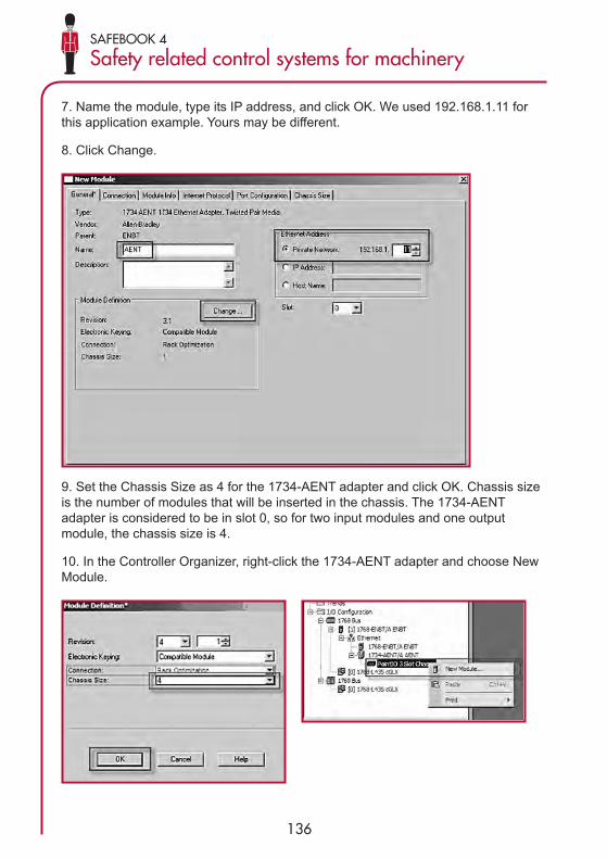
136
SAFEBOOK 4
Safety related control systems for machinery
7. Name the module, type its IP address, and click OK. We used 192.168.1.11 forthis application example. Yours may be different.
8. Click Change.
9. Set the Chassis Size as 4 for the 1734-AENT adapter and click OK. Chassis sizeis the number of modules that will be inserted in the chassis. The 1734-AENTadapter is considered to be in slot 0, so for two input modules and one outputmodule, the chassis size is 4.
10. In the Controller Organizer, right-click the 1734-AENT adapter and choose NewModule.

SAFEBOOK 4
Application example using SISTEMA
137
11. Expand Safety, select the 1734-IB8S module, and click OK.
12. In the New Module dialog box, name the device ‘CellGuard_1’and click Change.
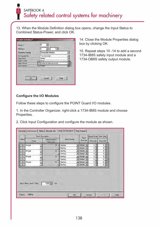
138
SAFEBOOK 4
Safety related control systems for machinery
13. When the Module Definition dialog box opens, change the Input Status toCombined Status-Power, and click OK.
14. Close the Module Properties dialogbox by clicking OK.
15. Repeat steps 10 -14 to add a second1734-IB8S safety input module and a1734-OB8S safety output module.
Configure the I/O Modules
Follow these steps to configure the POINT Guard I/O modules.
1. In the Controller Organizer, right-click a 1734-IB8S module and chooseProperties.
2. Click Input Configuration and configure the module as shown.

SAFEBOOK 4
Application example using SISTEMA
139
3. Click Test Output and configure the module as shown.
4. Click OK.
5. In the Controller Organizer, right-click the second 1734-IB8S module and chooseProperties.
6. Click Input Configuration and configure the module as shown.

140
SAFEBOOK 4
Safety related control systems for machinery
7. Click Test Output and configure the module as shown.
8. Click OK.
9. In the Controller Organizer, right-click the 1734-OB8S module and chooseProperties.
10. Click Output Configuration and configure the module as shown.
11. Click OK.

SAFEBOOK 4
Application example using SISTEMA
141
Programming
The Dual Channel Input Stop (DCS) instruction monitors dual-input safety deviceswhose main function is to stop a machine safely, for example, an E-stop, lightcurtain, or safety gate. This instruction can only energize Output 1 when both safetyinputs, Channel A and Channel B, are in the active state as determined by the InputType parameter, and the correct reset actions are carried out. The DCS instructionmonitors dual-input channels for consistency (Equivalent – Active High) and detectsand traps faults when the inconsistency is detected for longer than the configuredDiscrepancy Time (ms). The Configurable Redundant Output (CROUT) instructioncontrols and monitors redundant outputs. The reaction time for output feedback isconfigurable. The instruction supports positive and negative feedback signals.
The safety application code in the safety output routine prevents outputs fromrestarting if the input channel resets automatically, providing anti-tiedownfunctionality for the Circuit Reset.

142
SAFEBOOK 4
Safety related control systems for machinery
Falling Edge ResetEN ISO 13849-1 stipulates that instruction reset functions must occur on fallingedge signals. To comply with this requirement, add a One Shot Falling instruction tothe reset code as shown below.
Performance Data
When configured correctly, each safety function can achieve a safety rating of PLe,CAT 4 according to EN ISO 13849.1 2008.
Calculations are based on operation 360 days per year for 16 hours per day with anactuation of the safety gate once every hour for a total of 5760 operations per year.The global E-stop function is tested once per month.

SAFEBOOK 4
Application example using SISTEMA
143
Each safety gate function can be represented as follows.
K1100S
K2100S
1734-OB8S1768-L43S1734-IB8SSensaGuardSS1
SubSystem 1 SubSystem 2 SubSystem 3 SubSystem 4 SubSystem 5

144
SAFEBOOK 4
Safety related control systems for machinery
The Estop function can be represented as follows.
This example, its SISTEMA calculation file and RSLogix 5000 application code canbe downloaded from:
www.discoverrockwellautomation.com
K1100S
K2100S
Estop 1S1
Estop 1S2
1734-OB8S1768-L43S1734-IB8S
SubSystem 1 SubSystem 2 SubSystem 3 SubSystem 4 SubSystem 5

SAFEBOOK 4
Application example using SISTEMA
145
For more information about the products used in this example, please refer toRockwell Automations literature library and search for publication numbershighlighted below. Alternatively visit www.ab.com for general product overviews.
The literature library url is: www.theautomationbookstore.com
Rockwell Automation has developed a set of similar examples which can bedownloaded from literature library. Access literature library and perform a search for‘SAFETY-AT’ in the search field, setting the drop down menu to ‘PublicationNumber’.
SISTEMA calculations and RSLogix 5000 application codes are available for someof the applications and can be downloaded from:
www.discoverrockwellautomation.com
Resource Description
Compact GuardLogix ControllersUser Manual.Publication: 1768-UM002
Provides information on configuring,operating, and maintaining CompactGuardLogix controllers
POINT Guard I/O Safety ModulesInstallation and User Manual.Publication: 1734-UM013
Provides information on installing,configuring, and operating POINTGuard I/O modules
GuardLogix Controller SystemsSafety Reference Manual.Publication: 1756-RM093
Contains detailed requirements forachieving and maintaining safetyratings with the GuardLogix controllersystem.
GuardLogix Safety ApplicationInstruction Set Reference Manual.Publication: 1756-RM095
Provides detailed information on theGuardLogix Safety ApplicationInstruction Set.
Safety Accelerator Toolkit forGuardLogix Systems,Quick Start Guide.Publication: IASIMP-QS005
Provides a step-by-step guide to usingthe design, programming, anddiagnostic tolls in the SafetyAccelerator Toolkit.
Safety Products CalatoguePublication: S117-CA001A
A comprehensive publication whichincludes safety products, applivationexamples and useful information

146
SAFEBOOK 4
Safety related control systems for machineryM
TTFd
for
each
cha
nnel
in Y
ears
Aver
age
prob
abili
ty o
f a d
ange
rous
failu
re p
er h
our (
1/h)
and
cor
resp
ondi
ng p
erfo
rman
ce le
vel (
PL)
Cat
. BPL
Cat
. 1PL
Cat
. 2PL
Cat
. 2PL
Cat
. 3PL
Cat
. 3PL
Cat
. 4PL
DC
avg
= no
neD
Cav
g=
none
DC
avg
= lo
wD
Cav
g=
med
ium
DC
avg
= lo
wD
Cav
g=
med
ium
DC
avg
= hi
gh
33,8
0 x 10
-5a
2,58 x
10-5
a1,9
9 x 10
-5A
1,26 x
10-5
a6,0
9 x 10
-6b
3,33,4
6 x 10
-5a
2,33 x
10-5
a1,7
9 x 10
-5A
1,13 x
10-5
a5,4
1 x 10
-6b
3,63,1
7 x 10
-5a
2,13 x
10-5
a1,6
2 x 10
-5a
1,03 x
10-5
a4,8
6 x 10
-6b
3,92,9
3 x 10
-5a
1,95 x
10-5
a1,4
8 x 10
-5a
9,37 x
10-6
b4,4
0 x 10
-6b
4,32,6
5 x 10
-5a
1,76 x
10-5
a1,3
3 x 10
-5a
8,39 x
10-6
b3,8
9 x 10
-6b
4,72,4
3 x 10
-5a
1,60 x
10-5
a1,2
0 x 10
-5a
7,58 x
10-6
b3,4
8 x 10
-6b
5,12,2
4 x 10
-5a
1,47 x
10-5
a1,1
0 x 10
-5a
6,91 x
10-6
b3,1
5 x 10
-6b
5,62,0
4 x 10
-5a
1,33 x
10-5
a9,8
7 x 10
-6b
6,21 x
10-6
b2,8
0 x 10
-6c
6,21,8
4 x 10
-5a
1,19 x
10-5
a8,8
0 x 10
-6b
5,53 x
10-6
b2,4
7 x 10
-6c
6,81,6
8 x 10
-5a
1,08 x
10-5
a7,9
3 x 10
-6b
4,98 x
10-6
b2,2
0 x 10
-6c
7,51,5
2 x 10
-5a
9,75 x
10-6
b7,1
0 x 10
-6b
4,45 x
10-6
b1,9
5 x 10
-6c
8,21,3
9 x 10
-5a
8,87 x
10-6
b6,4
3 x 10
-6b
4,02 x
10-6
b1,7
4 x 10
-6c
9,11,2
5 x 10
-5a
7,94 x
10-6
b5,7
1 x 10
-6b
3,57 x
10-6
b1,5
3 x 10
-6c
101,1
4 x 10
-5a
7,18 x
10-6
b5,1
4 x 10
-6b
3,21 x
10-6
b1,3
6 x 10
-6c
111,0
4 x 10
-5a
6,44 x
10-6
b4,5
3 x 10
-6b
2,81 x
10-6
c1,1
8 x 10
-6c
129,5
1 x 10
-5b
5,84 x
10-6
b4,0
4 x 10
-6b
2,49 x
10-6
c1,0
4 x 10
-6c
138,7
8 x 10
-5b
5,33 x
10-6
b3,6
4 x 10
-6b
2,23 x
10-6
c9,2
1 x 10
-7d
157,6
1 x 10
-6b
4,53 x
10-6
b3,0
1 x 10
-6b
1,82 x
10-6
c7,4
4 x 10
-7d
167,3
1 x 10
-6b
4,21 x
10-6
b2,7
7 x 10
-6c
1,67 x
10-6
c6,7
6 x 10
-7d

SAFEBOOK 4
System design according to EN ISO 13849-1:2008
147
MTT
Fd fo
rea
ch c
hann
elin
Yea
rs
Aver
age
prob
abili
ty o
f a d
ange
rous
failu
re p
er h
our (
1/h)
and
cor
resp
ondi
ng p
erfo
rman
ce le
vel (
PL)
Cat
. BPL
Cat
. 1PL
Cat
. 2PL
Cat
. 2PL
Cat
. 3PL
Cat
. 3PL
Cat
. 4PL
DC
avg
= no
neD
Cav
g=
none
DC
avg
= lo
wD
Cav
g=
med
ium
DC
avg
= lo
wD
Cav
g=
med
ium
DC
avg
= hi
gh
186,3
4 x 10
-6b
3,68 x
10-6
b2,3
7 x 10
-6c
1,41 x
10-6
c5,6
7 x 10
-7d
205,7
1 x 10
-6b
3,26 x
10-6
b2,0
6 x 10
-6c
1,22 x
10-6
c4,8
5 x 10
-7d
225,1
9 x 10
-6b
2,93 x
10-6
c1,8
2 x 10
-6c
1,07 x
10-6
c4,2
1 x 10
-7d
244,7
6 x 10
-6b
2,65 x
10-6
c1,6
2 x 10
-6c
9,47 x
10-7
d3,7
0 x 10
-7d
274,2
3 x 10
-6b
2,32 x
10-6
c1,3
9 x 10
-6c
8,04 x
10-7
d3,1
0 x 10
-7d
303,8
0 x 10
-6b
2,06 x
10-6
c1,2
1 x 10
-6c
6,94 x
10-7
d2,6
5 x 10
-7d
9,54 x
10-8
e
333,4
6 x 10
-6b
1,85 x
10-6
c1,0
6 x 10
-6c
5,94 x
10-7
d2,3
0 x 10
-7d
8,57 x
10-8
e
363,1
7 x 10
-6b
1,67 x
10-6
c9,3
9 x 10
-7d
5,16 x
10-7
d2,0
1 x 10
-7d
7,77 x
10-8
e
392,9
3 x 10
-6c
1,53 x
10-6
c8,4
0 x 10
-7d
4,53 x
10-7
d1,7
8 x 10
-7d
7,11 x
10-8
e
432,6
5 x 10
-6c
1,37 x
10-6
c7,3
4 x 10
-7d
3,87 x
10-7
d1,5
4 x 10
-7d
6,37 x
10-8
e
472,4
3 x 10
-6c
1,24 x
10-6
c6,4
9 x 10
-7d
3,35 x
10-7
d1,3
4 x 10
-7d
5,76 x
10-8
e
512,2
4 x 10
-6c
1,13 x
10-6
c5,8
0 x 10
-7d
2,93 x
10-7
d1,1
9 x 10
-7d
5,26 x
10-8
e
562,0
4 x 10
-6c
1,02 x
10-6
c5,1
0 x 10
-7d
2,52 x
10-7
d1,0
3 x 10
-7d
4,73 x
10-8
e
621,8
4 x 10
-6c
9,06 x
10-7
d4,4
3 x 10
-7d
2,13 x
10-7
d8,8
4 x 10
-8e
4,22 x
10-8
e
681,6
8 x 10
-6c
8,17 x
10-7
d3,9
0 x 10
-7d
1,84 x
10-7
d7,6
8 x 10
-8e
3,80 x
10-8
e
751,5
2 x 10
-6c
7,31 x
10-7
d3,4
0 x 10
-7d
1,57 x
10-7
d6,6
2 x 10
-8e
3,41 x
10-8
e
821,3
9 x 10
-6c
6,61 x
10-7
d3,0
1 x 10
-7d
1,35 x
10-7
d5,7
9 x 10
-8e
3,08 x
10-8
e
911,2
5 x 10
-6c
5,88 x
10-7
d2,6
1 x 10
-7d
1,14 x
10-7
d4,9
4 x 10
-8e
2,74 x
10-8
e
100
1,14 x
10-6
c5,2
8 x 10
-7d
2,29 x
10-7
d1,0
1 x 10
-7d
4,29 x
10-8
e2,4
7 x 10
-8e

148
SAFEBOOK 4
Safety related control systems for machinery

Publication: SAFEBK-RM002B-EN-P —March 2011 © 2011 Rockwell Automation, Inc. All Rights Reserved. Superceedes Publication: SAFEBK-RM002A-EN-P


