
RWS300B
EVALUATION DATA
型式データ
TDK-Lambda A261-53-01D

RWS300BINDEX
1. 測定方法 Evaluation Method PAGE1.1 測定回路 Circuit used for determination
測定回路1 Circuit 1 used for determination .............................................................................................................T-1静特性 Steady state data通電ドリフト特性 Warm up voltage drift characteristics出力保持時間特性 Hold up time characteristics出力立ち上がり特性 Output rise characteristics出力立ち下がり特性 Output fall characteristics過電流保護特性 Over current protection (OCP) characteristics過電圧保護特性 Over voltage protection (OVP) characteristics入力電圧瞬停特性 Response to brown out characteristics入力電流波形 Input current waveform
測定回路2 Circuit 2 used for determination ..............................................................................................................................T-1過渡応答(負荷急変)特性 Dynamic load response characteristics
測定回路3 Circuit 3 used for determination .....................................................................................................................T-2入力サージ電流(突入電流)波形 Inrush current waveform
測定回路4 Circuit 4 used for determination .....................................................................................................................T-2リーク電流特性 Leakage current characteristics
測定回路5 Circuit 5 used for determination .....................................................................................................................T-3出力リップル、ノイズ波形 Output ripple and noise waveform
測定構成 Configuration used for determination ........................................................................................................................T-3EMI特性 Electro-Magnetic Interference characteristics(a) 雑音端子電圧 (帰還ノイズ) Conducted Emission(b) 雑音電界強度 (放射ノイズ) Radiated Emission
1.2 使用測定機器 List of equipment used ....................................................................................................................................T-4
1.3 評価負荷条件 Load conditions ..........................................................................................................................................T-4
TDK-Lambda

RWS300B
2. 特性データ Characteristics
2.1 静特性 Steady state data
(1) 入力・負荷・温度変動/出力起動・遮断電圧
Regulation - line and load, Temperature drift / Start up voltage and Drop out voltage ..........................................................................................T-5
(2) リップルノイズ電圧対入力電圧
Ripple noise voltage vs. Input voltage ....................................................................................................................................T-6
(3) 効率 ・ 力率対出力電流 Efficiency and Power factor vs. Output current .......................................................................................................................................T-7
(4) 入力電力対出力電流 Input power vs. Output current ..........................................................................................................T-8
(5) 入力電流対出力電流 Input current vs. Output current ..........................................................................................................T-9
2.2 通電ドリフト特性 Warm up voltage drift characteristics ............................................................................................................T-10
2.3 出力保持時間特性 Hold up time characteristics ..................................................................................................................................T-10
2.4 出力立ち上がり特性 Output rise characteristics .............................................................................................................................................................T-11
2.5 出力立ち下がり特性 Output fall characteristics ................................................................................................................................................T-12
2.6 過電流保護特性 Over current protection (OCP) characteristics ............................................................................................................T-13
2.7 過電圧保護特性 Over voltage protection (OVP) characteristics ...................................................................................T-13
2.8 過渡応答(負荷急変)特性 Dynamic load response characteristics .................................................................................T-14
2.9 入力電圧瞬停特性 Response to brown out characteristics ..........................................................................................T-15
2.10 入力サージ電流(突入電流)波形 Inrush current waveform .........................................................................................................................................T-16
2.11 高調波成分 Input current harmonics ...............................................................................................................................................................................................T-17
2.12 入力電流波形 Input current waveform ......................................................................................................................................................................................................................T-17
2.13 リーク電流特性 Leakage current characteristics ............................................................................................................T-18
2.14 出力リップル、ノイズ波形 Output ripple and noise waveform ............................................................................T-19
2.15 EMI特性 Electro-Magnetic Interference characteristics .........................................................................................................................................................T-20~23
使用記号 Terminology used
定義 Definition
Vin ......... 入力電圧 Input voltage
Vout ......... 出力電圧 Output voltageIin ......... 入力電流 Input currentIout ......... 出力電流 Output current
Ta ......... 周囲温度 Ambient temperature
f ......... 周波数 Frequency
TDK-Lambda
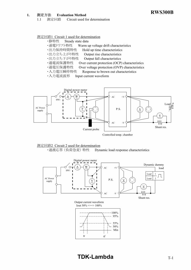
RWS300B1. 測定方法 Evaluation Method1.1 測定回路 Circuit used for determination
測定回路1 Circuit 1 used for determination・静特性 Steady state data・通電ドリフト特性 Warm up voltage drift characteristics・出力保持時間特性 Hold up time characteristics・出力立ち上がり特性 Output rise characteristics・出力立ち下がり特性 Output fall characteristics・過電流保護特性 Over current protection (OCP) characteristics・過電圧保護特性 Over voltage protection (OVP) characteristics・入力電圧瞬停特性 Response to brown out characteristics・入力電流波形 Input current waveform
測定回路2 Circuit 2 used for determination・過渡応答 (負荷急変) 特性 Dynamic load response characteristics
Controlled temp. chamber
AC Powersupply
A W
V
AC
AC
P.S.
V
V
+V
-V
Shunt res.
Load
Digital power meter
SW1
Current probe
tr tf
100%95%
Output current waveformIout 50% <==> 100%
AC Powersupply
A W
V
AC
AC
P.S.
Load 1
Load 2
V
V
+V
-V
Shunt res.
Dynamic dummyload
Digital power meter
SW1
55%50%Min
TDK-Lambda T-1

RWS300B
測定回路3 Circuit 3 used for determination・入力サージ電流 (突入電流) 波形 Inrush current waveform
測定回路4 Circuit 4 used for determination・リーク電流特性 Leakage current characteristics
接地Earth
V
VV
W
Leakagecurrentmeter
AC
AC
P.S.
+V
-V
Shunt res.
Load
Digital power meter
Isolationtrans
AC AC
AC AC
AC Powersupply
FG FG
A
A W
V
AC
AC
P.S.
V
V
+V
-V
Shunt res.
Load
Digital power meter
Current probe
Slide Reg.
Dynamic dip
simulator
TDK-Lambda T-2

RWS300B
測定回路5 Circuit 5 used for determination・出力リップル、ノイズ波形 Output ripple and noise waveform
測定構成 Configuration used for determination・EMI特性 Electro-Magnetic Interference characteristics (a) 雑音端子電圧 (帰還ノイズ)
Conducted Emission
(b) 雑音電界強度 (放射ノイズ)Radiated Emission
水平大地面Horizontal ground plane
アルミ板Aluminum plate
供試機器(接地)D.U.T (Earthed) アルミ板
Aluminum plate
垂直基準大地面
(2m × 2m)Vertical groundreference plane
アンテナAntenna
EMI Test receiver spectrum analyzerpre amp.
水平大地面Horizontal ground plane
D=3m
H=80cm台Stand
入力電源AC Power supply
ターンテーブルTurn table
電源ケーブルPower cable
D=40cm擬似電源回路網AMN 50Ω/50uH
EMI Test receiverspectrum analyzer
供試機器(接地)D.U.T (Earthed)
D=80cm
H=80cm台Stand
入力電源AC Power supply
電源ケーブルPower cable
接地Earth
接地Earth
AC Powersupply
A W
V
AC
AC
P.S.
+V
-V
Load
Digital power meter
SW
R
R : 50ΩC1 : 0.1uF Film cap.C2 : 100uF Elect cap.C3 : 4700pF Ceramic cap.
Coaxial cable1.5m 50Ω
OscilloscopeBandwith : 100MHz
150mm
+
C1 C2C3
TDK-Lambda T-3

RWS300B1.2 使用測定機器 List of equipment used
EQUIPMENT USED MANUFACTURER MODEL NO.
1 DIGITAL STORAGE OSCILLOSCOPE YOKOGAWA ELECT. DL9040L / DLM2054
2 DIGITAL MULTIMETER AGILENT 34970A
3 DIGITAL POWER METER YOKOGAWA ELECT. WT110 / WT210
4 CURRENT PROBE YOKOGAWA ELECT. 701928 / 701930
5 DYNAMIC DUMMY LOAD TAKASAGO FK-600L / FK-1000L
6 DUMMY LOAD PCN RHF250 SIRIES
7 SLIDE REGULATOR MATSUNAGA S3-24100
8 ISOLATION TRANS MATSUNAGA 3WTC-50K
9 CVCF TAKASAGO AA2000XG
10 CVCF NF ES10000S
11 LEAKAGE CURRENT METER HIOKI 3156
12 DYNAMIC DIP SIMULATOR TAKAMISAWA PSA-210
13 CONTROLLED TEMP. CHAMBER ESPEC SU-641 / SH-240
14 EMI TEST RECEIVER / SPECTRUM ANALYZER ROHDE & SCHWARZ ESCI
15 PRE AMP. SONOMA 310N
16 AMN SCHWARZBECK NNLK8121
17 ANTENNA SCHWARZBECK CBL6111D
18 HARMONIC / FLICKER ANALYZER KIKUSUI KHA1000
19 SINGLE-PHASE MASTER NF 4420
20 REFERENCE IMPEDANCE NETWORK 20A NF 4150
21 MULTI OUTLET UNIT KIKUSUI OT01-KHA
1.3 評価負荷条件 Load conditions
*入力電圧が110VAC以下の場合、下記のとおり出力ディレーティングが必要です。 Output derating is needed when input voltage is 110VAC or less.
Output voltage : 5V, 12V, 24VVin Iout : Full load 5V 12V 24V
110 - 265VAC 100% 50A 25A 12.5A100VAC 92% 46A 23A 11.5A85VAC 80% 40A 20A 10.0A
TDK-Lambda T-4

RWS300B2. 特性データ Characteristics
2.1 静特性 Steady state data(1) 入力・負荷・温度変動/出力起動・遮断電圧
Regulation - line and load, Temperature drift / Start up voltage and Drop out voltage
5V 1. Regulation - line and load Condition Ta : 25 ℃Iout \ Vin 100VAC 110VAC 200VAC 265VAC Line regulation
0% 5.036V 5.036V 5.036V 5.036V 0mV50% 5.022V 5.022V 5.022V 5.022V 0mV
Full load 5.011V 5.009V 5.009V 5.009V 0mV25mV 27mV 27mV 27mV
0.500% 0.540% 0.540% 0.540%2. Temperature drift Conditions Vin : 110 VAC
Iout : Full load Ta -10℃ +25℃ +50℃ Temperature stability
Vout 5.009V 5.009V 5.005V 4mV 0.080%3. Start up voltage and Drop out voltage Conditions Ta : 25 ℃
Iout : 100 %Start up voltage (Vin) 75VACDrop out voltage (Vin) 59VAC
12V 1. Regulation - line and load Condition Ta : 25 ℃Iout \ Vin 100VAC 110VAC 200VAC 265VAC Line regulation
0% 12.027V 12.028V 12.027V 12.027V 1mV50% 12.017V 12.016V 12.017V 12.017V 1mV
Full load 12.006V 12.003V 12.003V 12.003V 0mV21mV 25mV 24mV 24mV
0.175% 0.208% 0.200% 0.200%2. Temperature drift Conditions Vin : 110 VAC
Iout : Full load Ta -10℃ +25℃ +50℃ Temperature stability
Vout 12.011V 12.003V 12.003V 8mV 0.067%3. Start up voltage and Drop out voltage Conditions Ta : 25 ℃
Iout : 100 %Start up voltage (Vin) 76VACDrop out voltage (Vin) 67VAC
24V 1. Regulation - line and load Condition Ta : 25 ℃Iout \ Vin 100VAC 110VAC 200VAC 265VAC Line regulation
0% 24.018V 24.018V 24.017V 24.017V 1mV50% 24.013V 24.013V 24.013V 24.013V 0mV
Full load 24.011V 24.009V 24.009V 24.009V 0mV7mV 9mV 8mV 8mV
0.029% 0.038% 0.033% 0.033%2. Temperature drift Conditions Vin : 110 VAC
Iout : Full load Ta -10℃ +25℃ +50℃ Temperature stability
Vout 24.042V 24.009V 24.003V 39mV 0.163%3. Start up voltage and Drop out voltage Conditions Ta : 25 ℃
Iout : 100 %Start up voltage (Vin) 76VACDrop out voltage (Vin) 62VAC
※1 Line regulation : 110VAC - 265VAC
Load regulation
Load regulation
0.000%0.000%0.000%
0.008%
Load regulation
0.008%0.000%
0.004%0.000%0.000%
※1
※1
※1
TDK-Lambda T-5

RWS300B(2) リップルノイズ電圧対入力電圧Ripple noise voltage vs. Input voltage Conditions Iout : Full load
Ta : -10 ℃25 ℃50 ℃
5V
12V
24V
0
20
40
60
80
100
120
140
50 100 150 200 250
Rip
ple
nois
e vo
ltage
(mV
)
Input voltage (VAC)
0
20
40
60
80
100
120
140
50 100 150 200 250
Rip
ple
nois
e vo
ltage
(mV
)
Input voltage (VAC)
0
20
40
60
80
100
120
140
50 100 150 200 250
Rip
ple
nois
e vo
ltage
(mV
)
Input voltage (VAC)
TDK-Lambda T-6

RWS300B(3) 効率・力率対出力電流Efficiency and Power factor vs. Output current Conditions Vin : 100 VAC
110 VAC200 VAC265 VAC
Ta : 25 ℃
5V
12V
24V
50
60
70
80
90
0 20 40 60 80 100
Effic
ienc
y (%
)
Output current (%)
0.6
0.7
0.8
0.9
1.0
0 20 40 60 80 100Po
wer
fact
orOutput current (%)
50
60
70
80
90
0 20 40 60 80 100
Effic
ienc
y (%
)
Output current (%)
0.6
0.7
0.8
0.9
1.0
0 20 40 60 80 100
Pow
er fa
ctor
Output current (%)
50
60
70
80
90
0 20 40 60 80 100
Effic
ienc
y (%
)
Output current (%)
0.6
0.7
0.8
0.9
1.0
0 20 40 60 80 100
Pow
er fa
ctor
Output current (%)
TDK-Lambda T-7

RWS300B(4) 入力電力対出力電流Input power vs. Output current Conditions Vin : 100 VAC
110 VAC200 VAC265 VAC
Ta : 25 ℃
5V
Input powerIout : 0%
100VAC 3.6W110VAC 3.6W200VAC 4.0W265VAC 4.0W
12V
Input powerIout : 0%
100VAC 3.6W110VAC 3.7W200VAC 3.9W265VAC 4.0W
24V
Input powerIout : 0%
100VAC 3.6W110VAC 3.7W200VAC 3.9W265VAC 4.1W
Vin
Vin
Vin
0
100
200
300
400
0 20 40 60 80 100
Inpu
t pow
er (W
)
Output current (%)
0
100
200
300
400
0 20 40 60 80 100
Inpu
t pow
er (W
)
Output current (%)
0
100
200
300
400
0 20 40 60 80 100
Inpu
t pow
er (W
)
Output current (%)
TDK-Lambda T-8

RWS300B(5) 入力電流対出力電流Input current vs. Output current Conditions Vin : 100 VAC
110 VAC200 VAC265 VAC
Ta : 25 ℃
5V
Input currentIout : 0%
100VAC 0.06A110VAC 0.06A200VAC 0.07A265VAC 0.08A
12V
Input currentIout : 0%
100VAC 0.05A110VAC 0.06A200VAC 0.06A265VAC 0.08A
24V
Input currentIout : 0%
100VAC 0.06A110VAC 0.06A200VAC 0.07A265VAC 0.08A
Vin
Vin
Vin
0.0
1.0
2.0
3.0
4.0
0 20 40 60 80 100
Inpu
t cur
rent
(A)
Output current (%)
0.0
1.0
2.0
3.0
4.0
0 20 40 60 80 100
Inpu
t cur
rent
(A)
Output current (%)
0.0
1.0
2.0
3.0
4.0
0 20 40 60 80 100
Inpu
t cur
rent
(A)
Output current (%)
TDK-Lambda T-9

RWS300B2.2 通電ドリフト特性 2.3 出力保持時間特性
Warm up voltage drift characteristics Hold up time characteristics
Conditions Vin : 110 VAC Conditions Vin : 110 VACIout : Full load 200 VAC
Ta : 25 ℃ Ta : 25 ℃
5V
12V
24V
-0.4
-0.2
0.0
0.2
0.4
0 1 2 3 4 5 6 7 8
Out
put v
olta
ge d
rift (
%)
Time (hours)
-0.4
-0.2
0.0
0.2
0.4
0 1 2 3 4 5 6 7 8
Out
put v
olta
ge d
rift (
%)
Time (hours)
-0.4
-0.2
0.0
0.2
0.4
0 1 2 3 4 5 6 7 8
Out
put v
olta
ge d
rift (
%)
Time (hours)
10
100
1000
0 20 40 60 80 100H
old
up ti
me
(ms)
Output current (%)
10
100
1000
0 20 40 60 80 100
Hol
d up
tim
e (m
s)
Output current (%)
10
100
1000
0 20 40 60 80 100
Hol
d up
tim
e (m
s)
Output current (%)
TDK-Lambda T-10

RWS300B2.4 出力立ち上がり特性Output rise characteristics Conditions Vin : 100 VAC (A)
110 VAC (B)200 VAC (C)265 VAC (D)
Ta : 25 ℃
5VIout : 0% Iout : Full load
2V/DIV 200ms/DIV 2V/DIV 200ms/DIV
12VIout : 0% Iout : Full load
5V/DIV 200ms/DIV 5V/DIV 200ms/DIV
24VIout : 0% Iout : Full load
10V/DIV 200ms/DIV 10V/DIV 200ms/DIV
DC BA
DC BA
DC BA
DC B A
DC BA
DC BA
← V i n →
← 0 V →
←Vout→
← V i n →
← 0 V →
←Vout→
← V i n →
← 0 V →
←Vout→
TDK-Lambda T-11
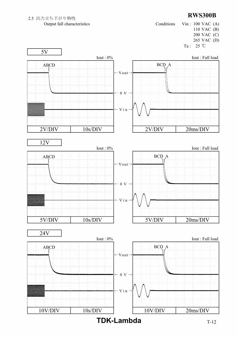
RWS300B2.5 出力立ち下がり特性Output fall characteristics Conditions Vin : 100 VAC (A)
110 VAC (B)200 VAC (C)265 VAC (D)
Ta : 25 ℃
5VIout : 0% Iout : Full load
2V/DIV 10s/DIV 2V/DIV 20ms/DIV
12VIout : 0% Iout : Full load
5V/DIV 10s/DIV 5V/DIV 20ms/DIV
24VIout : 0% Iout : Full load
10V/DIV 10s/DIV 10V/DIV 20ms/DIV
ABCD
ABCD BCD A
ABCD
BCD A
BCD A
← V i n →
← 0 V →
←Vout→
← V i n →
← 0 V →
←Vout→
← V i n →
← 0 V →
←Vout→
TDK-Lambda T-12

RWS300B2.6 過電流保護特性 2.7 過電圧保護特性Over current protection (OCP) characteristics Over voltage protection (OVP) characteristics
Conditions Vin : 110 VAC Conditions Vin : 100 VACTa : -10 ℃ Iout : 0 %
25 ℃ Ta : 25 ℃50 ℃
5V
2V/DIV 10s/DIV
12V
5V/DIV 10s/DIV
24V
10V/DIV 10s/DIV
0
2
4
6
8
10
12
0 50 100 150
Out
put v
olta
ge (V
)
Output current (%)
0
1
2
3
4
5
6
0 50 100 150
Out
put v
olta
ge (V
)
Output current (%)
0
5
10
15
20
25
0 50 100 150
Out
put v
olta
ge (V
)
Output current (%)
OVP Point
OVP Point
OVP Point
0V →
Vout →
0V →
Vout →
0V →
Vout →
TDK-Lambda T-13
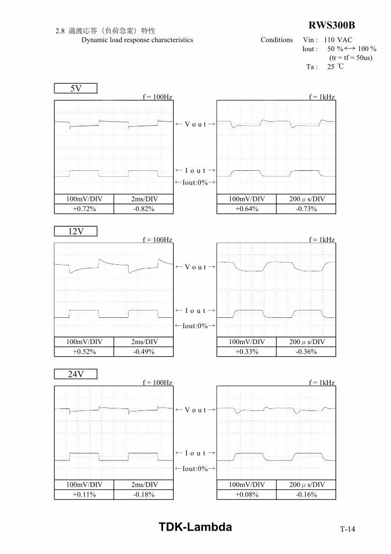
RWS300B2.8 過渡応答(負荷急変)特性Dynamic load response characteristics Conditions Vin : 110 VAC
Iout : 50 % 100 % (tr = tf = 50us)
Ta : 25 ℃
5Vf = 100Hz f = 1kHz
12Vf = 100Hz f = 1kHz
24Vf = 100Hz f = 1kHz
100mV/DIV 2ms/DIV 200μs/DIV+0.72% -0.82% +0.64% -0.73%
100mV/DIV
100mV/DIV 2ms/DIV 100mV/DIV 200μs/DIV+0.52% -0.49% +0.33% -0.36%
100mV/DIV 2ms/DIV 100mV/DIV 200μs/DIV+0.11% -0.18% +0.08% -0.16%
←Iout:0%→
← V o u t →
← I o u t →
←Iout:0%→
← V o u t →
← I o u t →
←Iout:0%→
← V o u t →
← I o u t →
TDK-Lambda T-14

RWS300B2.9 入力電圧瞬停特性
Response to brown out characteristics Conditions Ta : 25 ℃Iout : Full load
瞬停時間 Interruption timeA : 出力電圧が低下なし Output voltage does not drop.B : 出力電圧の低下が0Vまでいかない Output voltage drop down not reaching 0V.C : 出力電圧が0Vまで低下 Output voltage drops until 0V.
Vin : 110VAC Vin : 200VAC
A = 32ms, C = 33ms A = 34ms, C = 35ms
2V/DIV 50ms/DIV 2V/DIV 50ms/DIV
Vin : 110VAC Vin : 200VAC
A = 27ms, C = 28ms A = 28ms, C = 29ms
5V/DIV 50ms/DIV 5V/DIV 50ms/DIV
Vin : 110VAC Vin : 200VAC
A = 27ms, C = 28ms A = 28ms, C = 29ms
10V/DIV 50ms/DIV 10V/DIV 50ms/DIV
5V
12V
24V
A C A C
A C A C
A C A C
← 0 V →
← V i n →
← V o u t →
← 0 V →
← V i n →
← V o u t →
← 0 V →
← V i n →
← V o u t →
TDK-Lambda T-15

RWS300B2.10 入力サージ電流(突入電流)波形Inrush current waveform
12VConditions Vin : 100 VAC
Iout : Full load Ta : 25 ℃
10A/DIV 100ms/DIV 10A/DIV 100ms/DIV
Conditions Vin : 200 VACIout : Full load
Ta : 25 ℃
20A/DIV 100ms/DIV 20A/DIV 100ms/DIV
Switch on phase angle of input AC voltageφ = 0°
Switch on phase angle of input AC voltageφ = 90°
Switch on phase angle of input AC voltageφ = 0°
Switch on phase angle of input AC voltageφ = 90°
← Iin →
← Vin →
← Iin →
← Vin →
TDK-Lambda T-16

RWS300B2.11 高調波成分Input current harmonics Conditions Iout : Full load
Ta : 25 ℃12V
2.12 入力電流波形Input current waveform Conditions Iout : Full load
Ta : 25 ℃12V
Vin : 110VAC Vin : 200VAC
5A/DIV 5ms/DIV 5A/DIV 5ms/DIV
0.001
0.010
0.100
1.000
10.000
1 3 5 7 9 11 13 15 17 19 21 23 25 27 29 31 33 35 37 39
Har
mon
ic c
urre
nt (A
)
Harmonic order
0.001
0.010
0.100
1.000
10.000
1 3 5 7 9 11 13 15 17 19 21 23 25 27 29 31 33 35 37 39
Har
mon
ic c
urre
nt (A
)
Harmonic order
Vin : 110 VAC
Vin : 230 VAC
IEC61000-3-2 Limit (class A)
IEC61000-3-2 Limit (class A)
←Vin→
←Iin→
TDK-Lambda T-17

RWS300B2.13 リーク電流特性
Leakage current characteristics Conditions Iout : 0 %Full load
Ta : 25 ℃Equipment used : 3156 (HIOKI)
12V
f : 50 Hz
f : 60 Hz
0.0
0.1
0.2
0.3
0.4
0.5
80 120 160 200 240 280
Leak
age
curr
ent (
mA
)
Input voltage (VAC)
0.0
0.1
0.2
0.3
0.4
0.5
80 120 160 200 240 280
Leak
age
curr
ent (
mA
)
Input voltage (VAC)
TDK-Lambda T-18

RWS300B2.14 出力リップル、ノイズ波形Output ripple and noise waveform Conditions Vin : 110 VAC
Iout : Full load Ta : 25 ℃
20mV/DIV 2μs/DIV
20mV/DIV 2μs/DIV
20mV/DIV 2μs/DIV
5V
12V
24V
TDK-Lambda T-19

RWS300B2.15 EMI特性
Electro-Magnetic Interference characteristics Conditions Vin : 230 VACIout : Full load
Ta : 25 ℃ 雑音端子電圧
Conducted Emission
5VPhase : N
Ref. Limit MeasureData (dB) (dB)
QP 62.2 51.3
AV 52.2 39.7
東サービスセンター
Phase : L
Phase : LRef. Limit Measure
Data (dB) (dB)
QP 62.0 54.1
AV 52.0 48.1
EN55011-B,EN55032-B,FCC-Bの限界値はVCCI class Bの限界値と同じLimit of EN55011-B,EN55032-B,FCC-B are same as its VCCI class B.
(243kHz)Point B
Point A(238kHz)
A
B VCCI Class BQP Limit
VCCI Class BAV Limit
VCCI Class BAV Limit
VCCI Class BQP Limit
TDK-Lambda T-20
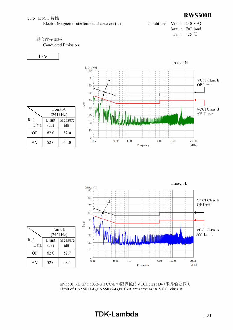
RWS300B2.15 EMI特性
Electro-Magnetic Interference characteristics Conditions Vin : 230 VACIout : Full load
Ta : 25 ℃ 雑音端子電圧
Conducted Emission
12VPhase : N
Ref. Limit MeasureData (dB) (dB)
QP 62.0 52.0
AV 52.0 44.0
Phase : L
Phase : LRef. Limit Measure
Data (dB) (dB)
QP 62.0 52.7
AV 52.0 48.1
EN55011-B,EN55032-B,FCC-Bの限界値はVCCI class Bの限界値と同じLimit of EN55011-B,EN55032-B,FCC-B are same as its VCCI class B.
Point B(242kHz)
Point A(241kHz)
A
B VCCI Class BQP Limit
VCCI Class BAV Limit
VCCI Class BQP Limit
VCCI Class BAV Limit
TDK-Lambda T-21
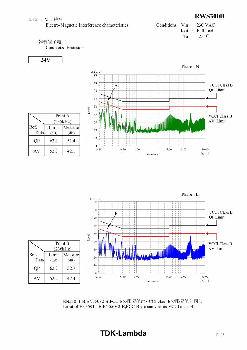
RWS300B2.15 EMI特性
Electro-Magnetic Interference characteristics Conditions Vin : 230 VACIout : Full load
Ta : 25 ℃ 雑音端子電圧
Conducted Emission
24VPhase : N
Ref. Limit MeasureData (dB) (dB)
QP 62.3 51.4
AV 52.3 42.1
Phase : L
Phase : LRef. Limit Measure
Data (dB) (dB)
QP 62.2 52.7
AV 52.2 47.4
EN55011-B,EN55032-B,FCC-Bの限界値はVCCI class Bの限界値と同じLimit of EN55011-B,EN55032-B,FCC-B are same as its VCCI class B.
Point B(236kHz)
Point A(235kHz)
A
B VCCI Class BQP Limit
VCCI Class BAV Limit
VCCI Class BAV Limit
VCCI Class BQP Limit
TDK-Lambda T-22

RWS300B2.15 EMI特性
Electro-Magnetic Interference characteristics Conditions Vin : 230 VACIout : Full load
Ta : 25 ℃ 雑音電界強度
Radiated Emission
HORIZONTAL VERTICAL
HORIZONTAL VERTICAL
HORIZONTAL VERTICAL
EN55011-B,EN55032-Bの限界値はVCCI class Bの限界値と同じLimit of EN55011-B,EN55032-B are same as its VCCI class B.
表示はピーク値Indication is peak values.
5V
12V
24V
QPQP
QP QP
QP QP
TDK-Lambda T-23


