Submitted to DOI: 10.1002/adma.201600660R2
Rotary Actuators Based on Pneumatically-Driven Elastomeric Structures
Xiangyu Gong, Ke Yang, Jingjin Xie, Yanjun Wang, Parth Kulkarni, Alexander S. Hobbs,
and Aaron D. Mazzeo*
Department of Mechanical and Aerospace Engineering
Rutgers, the State University of New Jersey
98 Brett Road
Piscataway, NJ 08854
E-mail: [email protected]
Keywords: soft robots; elastomers; locomotion; pneumatics; wheels
Submitted to
1
This paper describes a unique mechanism – a soft rotary actuator – based on peristaltic motion
of elastomeric materials, which consists of an inflatable stator paired with a rotor. Timed inflation
and deflation of the air-filled bladders in the stator enable controllable rotational speed of the rotor.
With two configurations, these rotary actuators are capable of having either an internal rotor for
winch/joint-like applications or an external rotor that can serve as a wheel. Fabrication of these
actuators employs the use of 3D-printed molds and millimeter-scale soft lithography.
Characterization of the relationships between speed, torque, and power for these actuators provides
a baseline for potential uses in locomotion and transportation of payloads. A squishy, four-wheeled
vehicle enabled by these actuators traveled at a speed of 3.7 cm/s, negotiated irregular terrain, and
endured mechanical impact from a drop eight times its height. This class of actuators extends the
potential functionality of soft robotic systems by providing rotational torque without requiring
bending or twisting.
Relying on the simple motion of bending, soft pneumatic actuators[1–4] have manipulated
fragile objects with pressurized fingers[4,5] and have crawled/undulated by changing their gaits[6].
Demonstrations of bending inflatable actuators have also included manta rays[3], camouflage[7],
resistance to puncture[8] and impact[9], elastomeric origami-like devices[10], power through
controlled explosions[11–13], fast flexing with low strain[14], endurance in adverse environments[15],
octopus arms[16–18], and robotic tentacles[19]. However, rotation plays a significant role in the design
of simple machines, as conventional robots often do not depend on bending actuators but employ
joints and torque-providing motors.
Recent advances in pneumatic, elastomeric actuators are not capable of delivering torque
through pure rotation. Soft belt-like robots[20,21] and a spherical robot[22] rolled, but the employed
class of structures – circular belts and spheres – required the locomotors to rotate completely upon
Submitted to
2
themselves. In addition, belt and sphere-based soft robots have yet to be optimized for transporting
payloads and handling pneumatic plumbing that can twist on itself.
While many soft robots have their basis in bio-inspired design or evolution[18,23,24], wheels on
axles – distinct from rolling mechanisms employed by animals (e.g., three-banded armadillos,
pangolins, wheel spiders, and pebble toads) – are a notable exception, as fully rotating components
do not exist in nature at the scale of millimeters[25,26]. In nature, the competitively advantageous
modes for soft creatures appear to resemble walking, crawling, and jumping, as verified through
genetic and evolutionary algorithms for both soft and hard virtual creatures[27–29]. Nonetheless,
wheel-and-axle assemblies are absent from nature, even though wheels have proven more
advantageous in certain scenarios. ,
Future wheeled robots with elastomeric components might find uses in search and rescue
missions in extreme environments or over varied terrains, such as an irregular tunnel that requires
a compliant body with large deformation, or a rugged lakebed under water. With the low sensitivity
of elastomers to magnetic fields, wheeled robots or rotary joints made of elastomers might
facilitate travel in space with limited exposure to radiation and cold. Another application might
include the manipulation of objects during magnetic resonance imaging (MRI). Lacking sharp or
metal components, soft rotary actuators may also serve as safe motors and be compatible with
future human-friendly robots or vehicles.
Peristalsis is common in nature. Peristaltic motion generated by the circular muscles of the
human esophagus helps push a bolus of food toward the stomach[30]. A variety of limbless crawlers,
such as earthworms, snails and snakes, use peristaltic mechanics and have inspired multiple worm-
like robots[31–33]. The design in this work combines peristaltic motion with the layout of a spinning
motor, which consists of a rotor and a stator. The stator is a circular, elastomeric structure with
Submitted to
3
embedded, hollow bladders. Each bladder has an inlet that provides pressurized air. We divide or
distribute the flow of pressurized air into multiple subgroups of bladders with each subgroup being
inflated and deflated sequentially. The sequential inflations and deflations generate a peristaltic
wave offset a radial distance from the rotational center and exert a set of circumferential forces to
provide torque on the rotor.
This work demonstrates two configurations of rotary actuators that enable the conversion of
peristaltic motion to torque. In the first configuration (Type 1), the inflatable stator surrounds a
hard plastic rotor. In the second configuration (Type 2), the stator sits inside a rotor made of
another elastomer. Figure 1a shows one complete cycle of sequential inflation of four subgroups
of bladders on stators without rotors for both types. These two configurations lend themselves to
unique sets of applications, such as winches (Type 1) and squishy wheels (Type 2).
As shown in Figure 1b-c, each time one subgroup of the air-filled bladders receives pneumatic
pressure, the four growing bladders in the stator exert force/torque on the rotor to make it turn. The
rotation stops when the bladders make contact with the internal corners of the rotor. This stop or
“locked” position is a stable state capable of maintaining its position. To move from this stable
state, we exhaust the inflated subgroup and inflate an adjacent subgroup of bladders to transition
the rotary actuator through another metastable step. The repeated sequence of inflation and
deflation generates the staggered turning of the rotor. With increases in the frequency of sequential
actuations, the continuous nature of the rotary motion increases.
Using computer-based, geometric models created in SolidWorks (Dassault), a three-
dimensional (3D) printer (FlashForge Creator) produced Type 1 rotors and molds for elastomeric
components. The material used for the 3D printing is a thermoplastic – acrylonitrile butadiene
styrene (ABS). The Supporting Information (Figure S1) discusses more details concerning

Submitted to
4
Figure 1. Basic configurations and sequential actuation of subgroups of embedded bladders for
two types of rotary actuators. (a) Subgroups of bladders inflating around fixed stators in peristaltic
fashion (12341…). Four different colors mark the four subgroups, respectively. (b) An
actuator with an internal rotor (Type 1) showing a step angle of 22.5°, along with rotation between
stable states (enclosed by the dashed lines). (c) An actuator with an external rotor (Type 2) showing
a step angle of 22.5° and rotation between stable states (enclosed by the dashed lines).
Submitted to
5
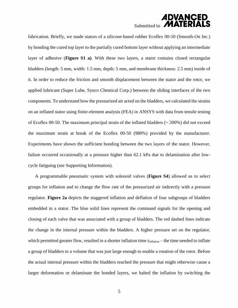
fabrication. Briefly, we made stators of a silicone-based rubber Ecoflex 00-50 (Smooth-On Inc.)
by bonding the cured top layer to the partially cured bottom layer without applying an intermediate
layer of adhesive (Figure S1 a). With these two layers, a stator contains closed rectangular
bladders (length: 5 mm, width: 1.5 mm, depth: 5 mm, and membrane thickness: 2.5 mm) inside of
it. In order to reduce the friction and smooth displacement between the stator and the rotor, we
applied lubricant (Super Lube, Synco Chemical Corp.) between the sliding interfaces of the two
components. To understand how the pressurized air acted on the bladders, we calculated the strains
on an inflated stator using finite-element analysis (FEA) in ANSYS with data from tensile testing
of Ecoflex 00-50. The maximum principal strain of the inflated bladders (~ 200%) did not exceed
the maximum strain at break of the Ecoflex 00-50 (980%) provided by the manufacturer.
Experiments have shown the sufficient bonding between the two layers of the stator. However,
failure occurred occasionally at a pressure higher than 62.1 kPa due to delamination after low-
cycle fatiguing (see Supporting Information).
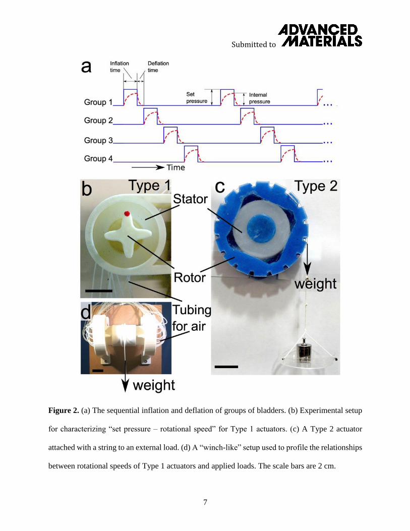
A programmable pneumatic system with solenoid valves (Figure S4) allowed us to select
groups for inflation and to change the flow rate of the pressurized air indirectly with a pressure
regulator. Figure 2a depicts the staggered inflation and deflation of four subgroups of bladders
embedded in a stator. The blue solid lines represent the command signals for the opening and
closing of each valve that was associated with a group of bladders. The red dashed lines indicate
the change in the internal pressure within the bladders. A higher pressure set on the regulator,
which permitted greater flow, resulted in a shorter inflation time tinflation – the time needed to inflate
a group of bladders to a volume that was just large enough to enable a rotation of the rotor. Before
the actual internal pressure within the bladders reached the pressure that might otherwise cause a
larger deformation or delaminate the bonded layers, we halted the inflation by switching the

Submitted to
6
position of the valve and exhausted the air in the bladders to the surrounding environment. Unlike
inflation times, which were dependent on the pressure set on the regulator, the deflation times
tdeflation remained consistent for a given volume of the inflated bladders. To measure the time of
deflation, we used a camera with a moderate speed (120 frames/second) to record the deflation of
each group (Figure S5, Movie S1). In this way, we found the average deflation times of Type 1
and Type 2 actuators were approximately 130 msec and 190 msec, respectively. Meanwhile, we
determined the static internal pressure in these inflated bladders (~ 48.3 kPa, 7 psi, for both Types)
with the minimum inflation that could enable the continual rotation of a rotor. Knowing this static
pressure, we estimated the corresponding minimum volumes of the inflated bladder for both
designs (Type 1: 8.0 cm3, Type 2: 3.3 cm3) with a gridded background (Figure S3 a, c).
The rotational speed of the actuators relied on both times of inflation and deflation for each
group of bladders. With an approach similar to that of controlling an electromagnetic motor by
changing the applied voltage, we manipulated the speed of the rotary actuator by varying the
pressure set on the regulator. With a specific inflation time corresponding to a varied set pressures,
we calculated rotational speeds with the following formula:
Rotational Speed (RPM) = (60 sec/min)(1000 msec/sec)
(16 groups/rotation)(tinflation
+ tdeflation
) (1)
The units of tinflation and tdeflation are milliseconds/group.
To understand the capabilities (i.e., rotational speeds and load capacity) of the actuators, we
characterized them in similar fashion to that of an electromagnetic motor. Figure 2b-c represent
the Type 1 and Type 2 actuators connected to the pneumatic system, respectively. By varying the
set pressure and timing as shown in Figure 2a, we experimentally mapped the set pressure–
inflation time (Figure 3a) and rotational speed–set pressure relationships (Figure 3b) by
Submitted to
7
Figure 2. (a) The sequential inflation and deflation of groups of bladders. (b) Experimental setup
for characterizing “set pressure – rotational speed” for Type 1 actuators. (c) A Type 2 actuator
attached with a string to an external load. (d) A “winch-like” setup used to profile the relationships
between rotational speeds of Type 1 actuators and applied loads. The scale bars are 2 cm.
Submitted to
8
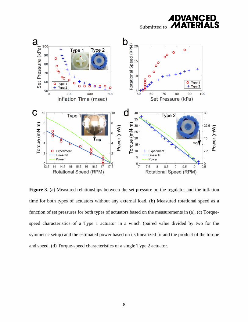
Figure 3. (a) Measured relationships between the set pressure on the regulator and the inflation
time for both types of actuators without any external load. (b) Measured rotational speed as a
function of set pressures for both types of actuators based on the measurements in (a). (c) Torque-
speed characteristics of a Type 1 actuator in a winch (paired value divided by two for the
symmetric setup) and the estimated power based on its linearized fit and the product of the torque
and speed. (d) Torque-speed characteristics of a single Type 2 actuator.
Submitted to
9
converting the inflation times to rotational speeds with Equation 1 and previously measured
deflation times.
For the Type 2 actuators, we directly attach an external load to the string (Figure 2c). For the
Type 1 actuators, however, we built a symmetric experimental setup (Figure 2d) to permit the
application of external loads (see Figure S6). We then inserted the shaft with rotor-shaped ends
into the stators. This “winch-like” setup permitted varying external loads and kept the rotors
balanced inside the stators when profiling the torque–rotational speed curve (Figure 3c). With
this setup, we divided the weight in half to get the external torque acting on each of the Type 1
actuators. For both actuators, we initially set a pressure of 68.9 kPa (10 psi) on the regulator to
make the actuators turn without any external loading. With increasing external loads on the
actuators, we observed larger inflation times to overcome increasing pressure-based forces and
friction between the rotor and stator. Thus, in similar fashion to conventional electromagnetic
rotors, higher torques resulted at lower speeds of rotation.
Figure 3a profiles the set pressures on the regulator corresponding to the desired inflation
times for each subgroup of bladders with no external load on the rotors. Figure 3b shows the
relationships between the rotational speed and the set pressures from the data shown in Figure 3a,
the previously measured deflation times, and Equation 1. In general, increasing the set pressure
on the regulator lead to a higher rotational speed, because the inflation time decreased due to an
increased flow rate. According to the measured results, Type 1 actuators achieved higher rotational
speed than Type 2 actuators with the same set pressures, which reflects the facts that the Type 1
actuators were less massive and had less friction with their stators than Type 2 actuators. The
bladders in both types inflated by approximately the same amount at the same rate, and the higher
speeds of Type 1 actuators than those of Type 2 actuators were also because the bladders acted at
Submitted to
10
a distance closer to the axis of rotation than in the Type 2 actuators. There was also a remarkable
change in the speed and release of kinetic energy for the Type 1 actuators at approximately 55.2
kPa (8 psi) caused by the snap-through behavior of the inflatable elastomers[34–37]. To verify the
snap-through behavior of the bladders embedded in the elastomeric stators, we monitored the real-
time internal pressure of a bladder that was under inflation (Figure S7 and Movie S9).
Figure 3c-d characterized the rotational speeds of the two types of actuators, respectively, as
a function of the torque at a specified pressure set on the regulator. We calculated the torque based
on the applied, hanging loads and their distance from the axis of rotation (diameter of the shaft of
the winch: 4.1 cm; outer diameter of the Type 2 actuator: 9.2 cm). At a fixed pressure of 69 kPa
(10 psi), starting with no load, the winch for Type 1 actuators rotated at a speed of 17 RPM, and
the Type 2 actuators had a rotational speed of 10.2 RPM. Generally, the rotational speeds of the
actuators decreased when the external loads increased, until the torque reached 6.5 mN·m for Type
1 actuators and 38 mN·m for Type 2 actuators. At that point, the actuators were no longer able to
bear the external torque or turn continually, with the rotors sliding backwards inside the stators.
Using linear regression, we fit the relationships between rotational speed and external torque to a
linear model (solid lines). In this way, we also estimated the power of the actuators as a function
of the speed of rotation. According to the calculated power – rotational speed curves (dashed lines)
in Figure 3c-d, the maximum values the actuators achieved were 8.4 mW (Type 1) and 26 mW
(Type 2), when the rotational speeds were at a minimum. The overall power of the Type 1 actuator
was lower than that of Type 2, but the Type 1 actuator achieved a higher rotational speed. In
addition to the capability of lifting payloads, we also demonstrated how the soft rotary actuators
were compatible with previously published pneumatic soft actuators (i.e., a soft gripper embedded

Submitted to
11
with PneuNets)[4]. A winch equipped with a soft gripper going up and down was able to grasp and
lift an object (Figure S8, Movie S3).
To demonstrate the application of the rotary actuators powered by the pneumatic system, we
built prototypes of squishy vehicles equipped with the actuators working as wheels with a diameter
of 9.2 cm. Combining multiple controllable motions, a two-wheeled vehicle demonstrated the
capability of navigating around an obstacle and had a top speed of 4.9 cm/s (Figure S9, Movie
S4). We also extended the two-wheeled device to a rover-like vehicle with four wheels (Figure
4a-b). A structure made of Ecoflex 00-50 served as a chassis to connect two two-wheeled modules.
At the same set pressure of 86.2 kPa (12.5 psi) used to drive the two-wheeled vehicle, we needed
longer inflation times (300 msec) to compensate for the extra mass of the chassis – total mass of
1.23 kg – and friction between stators and rotors. The rotational speed of each wheel was 7.7 RPM,
and therefore, the speed of the vehicle was 3.7 cm/sec (Figure 4c, Movie S5).
This four-wheeled vehicle puts forth several potential benefits to endurance and navigation
over varied terrains. First, there were not any rigid components in the entire vehicle, and the
elastomeric wheels/components helped absorb mechanical impact. A drop test from eight times its
height (0.72 m) did not cause any damage to the body or the actuators (Figure 4d, Movie S6) of
the vehicle. After bouncing and landing on the ground safely, the vehicle moved forward.
Second, navigation over difficult terrain with a naturally compliant set of wheels and
suspension suggests the potential of eliminating the complexity associated with rigid members and
multi-component suspensions for allowing wheels to maneuver over obstacles. In Figure 4e (and
Movie S7), the squishy vehicle negotiated a rocky terrain with a puddle. As shown, the chassis
made of Ecoflex 00-50 bent to comply with the rugged landscape. As an aside, the slight climb
from the puddle back to the higher ground was at a reduced linear speed, associated with a lower
Submitted to
12
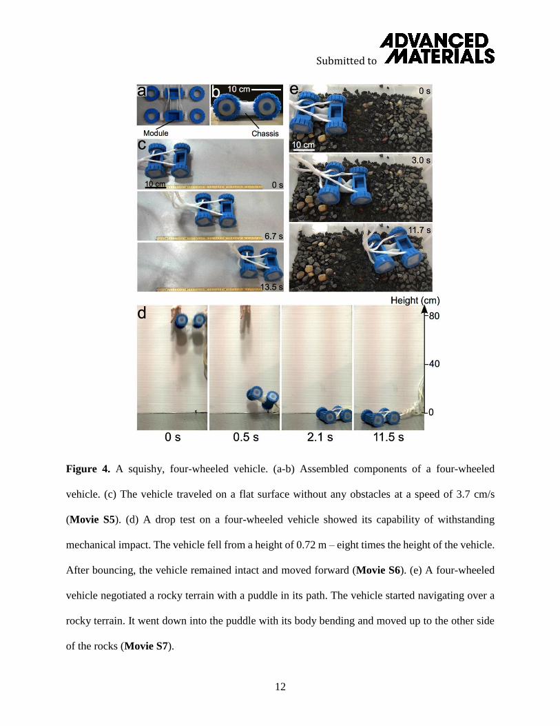
Figure 4. A squishy, four-wheeled vehicle. (a-b) Assembled components of a four-wheeled
vehicle. (c) The vehicle traveled on a flat surface without any obstacles at a speed of 3.7 cm/s
(Movie S5). (d) A drop test on a four-wheeled vehicle showed its capability of withstanding
mechanical impact. The vehicle fell from a height of 0.72 m – eight times the height of the vehicle.
After bouncing, the vehicle remained intact and moved forward (Movie S6). (e) A four-wheeled
vehicle negotiated a rocky terrain with a puddle in its path. The vehicle started navigating over a
rocky terrain. It went down into the puddle with its body bending and moved up to the other side
of the rocks (Movie S7).

Submitted to
13
angular velocity of the rotary actuators (i.e., a longer inflation time) with a higher pressure set on
the regulator.
Finally, the vehicle equipped with the actuators functioned not only in a dry environment but
also under water (Figure S10, Movie S8). In this example, the vehicle pushed a buoy and carried
a few rocks to compensate for the buoyancy of the underwater, air-filled cavities. With no metal
components and moisture-sensitive electronics on the vehicle itself, the tethered locomotor was
waterproof. Follow-up work might explore the resistance of the adhesives and silicones to long-
term exposure to water, while inspiring future low-cost amphibious vehicles.
To conclude, the soft rotary actuators in this work generated motion through biologically-
inspired peristalsis that used alternating inflation and deflation of pneumatic bladders. The two
types of rotary actuators employed complementary configurations of stators and rotors. For the
chosen geometries, the speed and torque of the soft actuators depended on three factors: pressure
and flow of the compressed air delivered to the bladders, timing of the solenoid valves, and the
load on the actuators. These rotary actuators have “torque-speed” characteristics similar to those
of conventional electromagnetic motors. The quantitative characterization might also serve as an
initial baseline for future soft, rotary devices. Unlike conventional electromagnetic motors, they
are also capable of locking at a fixed angle without the application of additional power (i.e., a
sealed inflatable bladder is able to maintain pressure and apply reactive forces to a rotor to maintain
a position).
The Type 1 actuators with a rigid, 3-D printed internal rotor demonstrated their use in winch-
like applications. Consisting of entirely soft components, the Type 2 actuators enabled the
fabrication of a squishy, wheeled vehicle with the ability to withstand mechanical impact, negotiate
Submitted to
14
rocky and wet terrains, and work under water as an amphibious vehicle. These actuators provided
rotational torque without bending and twisting.
Future uses of this work might include the design and fabrication of soft robotic joints and soft
wheels for enhanced locomotion. An on-board control system, such as a micropneumatic
manifold[38], and a compact air compressor used by resilient, untethered robots[15] might also make
it possible to fabricate future autonomous and untethered soft wheeled devices. For these potential
applications, outstanding technical challenges to be addressed include the development of
materials and mechanical sciences to understand the large deformation and cyclic fatigue of the
elastomeric bladders, delamination at the bonded interfaces, the role of rapid releases of kinetic
energy as the bladders pass through metastable snap-through instabilities, and modest outputs of
rotary, mechanical power. This work marks initial steps toward designing soft material-based
systems capable of millimeter-scale, continuous rotary actuation.
Acknowledgements
The authors acknowledge funding from Rutgers University through the School of Engineering,
the Department of Mechanical and Aerospace Engineering, the University Research Council, and
an A. Walter Tyson Assistant Professorship Award.

Submitted to
15
References
[1] K. Suzumori, S. Iikura, H. Tanaka, in 1991 IEEE Int. Conf. Robot. Autom. 1991 Proc.,
1991, pp. 1622–1627 vol.2.
[2] C.-P. Chou, B. Hannaford, IEEE Trans. Robot. Autom. 1996, 12, 90.
[3] K. Suzumori, S. Endo, T. Kanda, N. Kato, H. Suzuki, in 2007 IEEE Int. Conf. Robot.
Autom., 2007, pp. 4975–4980.
[4] F. Ilievski, A. D. Mazzeo, R. F. Shepherd, X. Chen, G. M. Whitesides, Angew. Chem. Int.
Ed. 2011, 50, 1890.
[5] E. Brown, N. Rodenberg, J. Amend, A. Mozeika, E. Steltz, M. R. Zakin, H. Lipson, H. M.
Jaeger, Proc. Natl. Acad. Sci. U. S. A. 2010, 107, 18809.
[6] R. F. Shepherd, F. Ilievski, W. Choi, S. A. Morin, A. A. Stokes, A. D. Mazzeo, X. Chen,
M. Wang, G. M. Whitesides, Proc. Natl. Acad. Sci. U. S. A. 2011, 108, 20400.
[7] S. A. Morin, R. F. Shepherd, S. W. Kwok, A. A. Stokes, A. Nemiroski, G. M. Whitesides,
Science 2012, 337, 828.
[8] R. F. Shepherd, A. A. Stokes, R. M. D. Nunes, G. M. Whitesides, Adv. Mater. 2013, 25,
6709.
[9] R. V. Martinez, A. C. Glavan, C. Keplinger, A. I. Oyetibo, G. M. Whitesides, Adv. Funct.
Mater. 2014, 24, 3003.
[10] R. V. Martinez, C. R. Fish, X. Chen, G. M. Whitesides, Adv. Funct. Mater. 2012, 22, 1376.
[11] R. F. Shepherd, A. A. Stokes, J. Freake, J. Barber, P. W. Snyder, A. D. Mazzeo, L.
Cademartiri, S. A. Morin, G. M. Whitesides, Angew. Chem. 2013, 125, 2964.
[12] M. T. Tolley, R. F. Shepherd, M. Karpelson, N. W. Bartlett, K. C. Galloway, M. Wehner,
R. Nunes, G. M. Whitesides, R. J. Wood, in 2014 IEEERSJ Int. Conf. Intell. Robots Syst.
IROS 2014, 2014, pp. 561–566.
[13] N. W. Bartlett, M. T. Tolley, J. T. B. Overvelde, J. C. Weaver, B. Mosadegh, K. Bertoldi,
G. M. Whitesides, R. J. Wood, Science 2015, 349, 161.
[14] B. Mosadegh, P. Polygerinos, C. Keplinger, S. Wennstedt, R. F. Shepherd, U. Gupta, J.
Shim, K. Bertoldi, C. J. Walsh, G. M. Whitesides, Adv. Funct. Mater. 2014, 24, 2163.
[15] M. T. Tolley, R. F. Shepherd, B. Mosadegh, K. C. Galloway, M. Wehner, M. Karpelson, R.
J. Wood, G. M. Whitesides, Soft Robot. 2014, 1, 213.
[16] L. Margheri, C. Laschi, B. Mazzolai, Bioinspir. Biomim. 2012, 7, 025004.
[17] B. Mazzolai, L. Margheri, M. Cianchetti, P. Dario, C. Laschi, Bioinspir. Biomim. 2012, 7,
025005.
[18] S. Kim, C. Laschi, B. Trimmer, Trends Biotechnol. 2013, 31, 287.
[19] R. V. Martinez, J. L. Branch, C. R. Fish, L. Jin, R. F. Shepherd, R. M. D. Nunes, Z. Suo, G.
M. Whitesides, Adv. Mater. 2013, 25, 205.
[20] N. Correll, Ç. D. Önal, H. Liang, E. Schoenfeld, D. Rus, in Exp. Robot. (Eds.: O. Khatib, V.
Kumar, G. Sukhatme), Springer Berlin Heidelberg, 2014, pp. 227–240.
[21] A. D. Marchese, C. D. Onal, D. Rus, in 2011 IEEERSJ Int. Conf. Intell. Robots Syst. IROS,
2011, pp. 756–761.
[22] K. W. Wait, P. J. Jackson, L. S. Smoot, in 2010 IEEE Int. Conf. Robot. Autom. ICRA, 2010,
pp. 3757–3762.
[23] D. Trivedi, C. D. Rahn, W. M. Kier, I. D. Walker, Appl. Bionics Biomech. 2008, 5, 99.
[24] R. Pfeifer, M. Lungarella, F. Iida, Commun ACM 2012, 55, 76.
[25] S. J. Gould, Nat. Hist. 1981, 90, 42.

Submitted to
16
[26] R. Dawkins, Sunday Times 1996, 24.
[27] K. Sims, in Proc. 21st Annu. Conf. Comput. Graph. Interact. Tech., ACM, New York, NY,
USA, 1994, pp. 15–22.
[28] K. Sims, Artif. Life 1994, 1, 353.
[29] N. Cheney, R. MacCurdy, J. Clune, H. Lipson, in Proc. 15th Annu. Conf. Genet. Evol.
Comput., ACM, New York, NY, USA, 2013, pp. 167–174.
[30] W. G. Paterson, GI Motil. Online 2006, DOI 10.1038/gimo13.
[31] S. Kim, E. Hawkes, K. Cho, M. Joldaz, J. Foleyz, R. Wood, in IEEERSJ Int. Conf. Intell.
Robots Syst. 2009 IROS 2009, 2009, pp. 2228–2234.
[32] S. Seok, C. D. Onal, K.-J. Cho, R. J. Wood, D. Rus, S. Kim, IEEEASME Trans. Mechatron.
2013, 18, 1485.
[33] A. D. Horchler, A. Kandhari, K. A. Daltorio, K. C. Moses, J. C. Ryan, K. A. Stultz, E. N.
Kanu, K. B. Andersen, J. A. Kershaw, R. J. Bachmann, H. J. Chiel, R. D. Quinn, Soft
Robot. 2015, 2, 135.
[34] A. N. Gent, Int. J. Non-Linear Mech. 2005, 40, 165.
[35] G. Mao, T. Li, Z. Zou, S. Qu, M. Shi, Int. J. Solids Struct. 2014, 51, 2109.
[36] T. Li, C. Keplinger, R. Baumgartner, S. Bauer, W. Yang, Z. Suo, J. Mech. Phys. Solids
2013, 61, 611.
[37] J. T. B. Overvelde, T. Kloek, J. J. A. D’haen, K. Bertoldi, Proc. Natl. Acad. Sci. 2015, 112,
10863.
[38] B. Mosadegh, A. D. Mazzeo, R. F. Shepherd, S. A. Morin, U. Gupta, I. Z. Sani, D. Lai, S.
Takayama, G. M. Whitesides, Lab. Chip 2013, 14, 189.
Submitted to DOI: 10.1002/adma.201600660R2
Rotary Actuators Based on Pneumatically-Driven Elastomeric Structures
Supporting Information
Xiangyu Gong, Ke Yang, Jingjin Xie, Yanjun Wang, Parth Kulkarni, Alexander S. Hobbs,
and Aaron D. Mazzeo*
Department of Mechanical and Aerospace Engineering
Rutgers, the State University of New Jersey
98 Brett Road
Piscataway, NJ 08854
E-mail: [email protected]
Keywords: soft robots; elastomers; locomotion; pneumatics; wheels
Submitted to
1
Rotary Actuators Based on Pneumatically-Driven Elastomeric Structures
Supporting Information
Fabrication of Soft Rotary Actuators
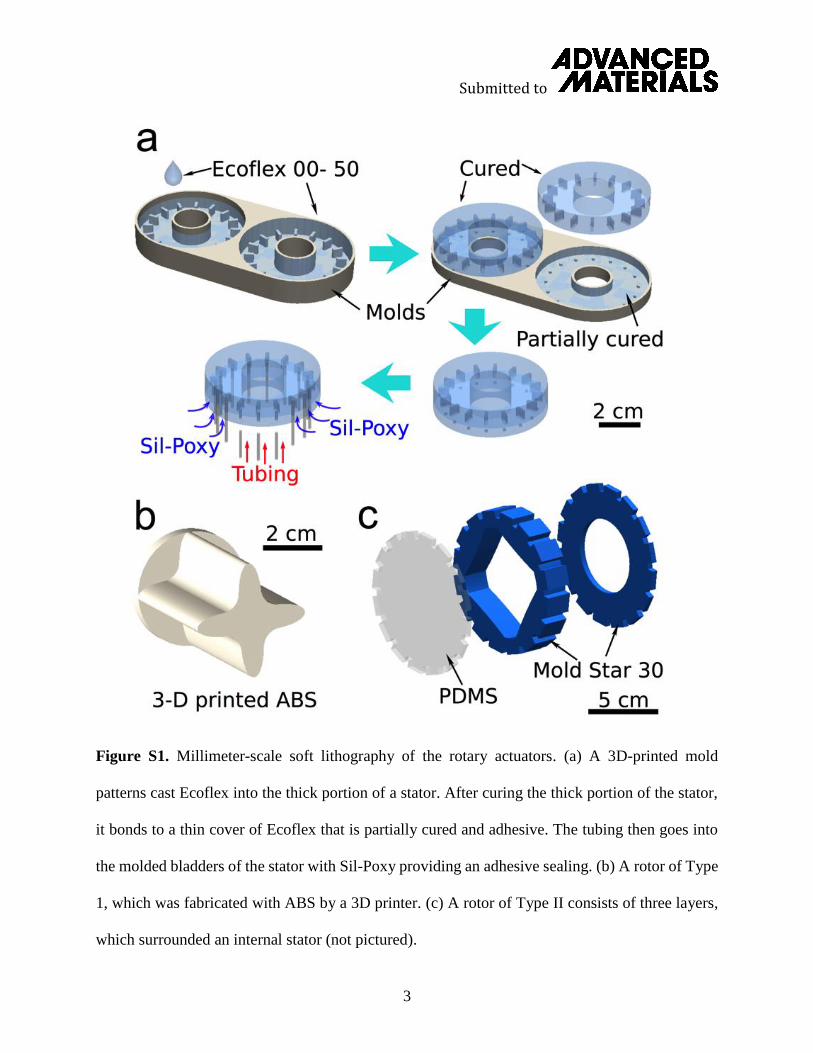
Fabrication of the stators (Figure S1 a) required the molding and assembly of two separate
components: one for the structure with groups of inflatable bladders (top layer) and one for a layer
to seal these chambers (bottom layer). We fabricated all the molds from a thermoplastic –
acrylonitrile butadiene styrene (ABS) – with a 3D printer (FlashForge Creator) using computer-
aid design. As shown in Figure S1a, we removed the top layer of the stator from the mold, cleaned
the surface of the top layer with isopropyl alcohol, and then put it on the partially-cured, adhesive-
bottom layer that still stayed in the mold. It required approximately 10 minutes for the bottom
layers to be partially cured at room temperature. After the bottom layer was fully cured, the
complete stator was ready for removal.
The designated holes printed on the bottom layer indicate the positions of the inlets for
compressed air. After punching 16 holes on the bottom layer with needles, we inserted silicone
rubber tubing (OD:1/16”, ID:1/32”) into each bladder through the holes. As the final step, we
sealed the gap between the tubing and the holes with silicone rubber adhesive Sil-Poxy (Smooth-
On Inc.). In general, the fabrication for the two types of stators was the same, and both of them
consisted of silicone-based elastomer. However, the fabrication and the materials of the two types
of rotors (Type 1: 3.65-cm diameter, Type 2: 9.2-cm diameter) are different. We fabricated the
hard internal rotor (Type 1) from ABS directly through the 3D printer (FlashForge Creator), using
computer-aid design (Figure S1 b). Meanwhile, Type 2 rotors were molded from a thermosetting
elastomer Mold Star 30 (Smooth-On Inc.).
Submitted to
2
For Type 2 actuators, the 3D printer (FlashForge Creator) produced the molds for the different
layers of the external rotor, and then we molded these layers (Figure S1 c). We bonded the
structured layers with Sil-Poxy. There are three layers: one layer with the main structure designed
to interact with the stator inside of it, one PDMS layer to constrain the slide on the axial direction
between the rotor and the stator, and one layer that constrained and fixed the stator on the other
side. The transparency of the PDMS layer also showed the internal structure and helped us monitor
how the rotor and the stator interacted when controlling an actuator. The material for the other two
layers (blue) is Mold Star 30 (Smooth-On Inc.). Mold Star 30 is a type of platinum silicone rubber,
which is also an elastomer, but it is harder than the Ecoflex series.
Step Angle
Similar to a conventional stepper motor driven by a series of pulsed signals, the inflation of
each group of bladders drives the rotor of the soft rotary actuator to turn by a fixed angle, which
we call a step angle. According to this principle of design, the rotor turns in discrete increments
from subgroup of embedded bladders to subgroup of embedded bladders. Thus, the number of
equally spaced bladders in the stator determines the step angle of the rotary actuator. In this paper,
there are 16 bladders in the stators. Thus, in each step (from one subgroup to the next subgroup),
the rotor turns by 22.5° (360°/16).
Friction between Sliding Components
There is friction between the stator and the rotor. In order to reduce the friction and smooth the
rotation, we applied lubricant between the sliding interfaces of the rotor and stator. After
qualitative experiments with different lubricants, including dish soap, water, silicone oil, and Super
Lube grease (Synco Chemical Corp.), we concluded that Super Lube grease provided the
smoothest rotation among these options. Super Lube grease is a nontoxic synthetic lubricant with
Submitted to
3
Figure S1. Millimeter-scale soft lithography of the rotary actuators. (a) A 3D-printed mold
patterns cast Ecoflex into the thick portion of a stator. After curing the thick portion of the stator,
it bonds to a thin cover of Ecoflex that is partially cured and adhesive. The tubing then goes into
the molded bladders of the stator with Sil-Poxy providing an adhesive sealing. (b) A rotor of Type
1, which was fabricated with ABS by a 3D printer. (c) A rotor of Type II consists of three layers,
which surrounded an internal stator (not pictured).
Submitted to
4
PTFE, and it does not drip or dry out easily. Moreover, it does not react with or significantly alter
the texture of the elastomers.
Uniaxial tensile tests of Ecoflex 00-50 and the Yeoh model
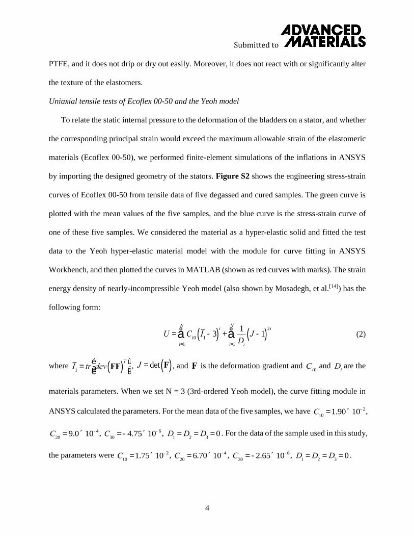
To relate the static internal pressure to the deformation of the bladders on a stator, and whether
the corresponding principal strain would exceed the maximum allowable strain of the elastomeric
materials (Ecoflex 00-50), we performed finite-element simulations of the inflations in ANSYS
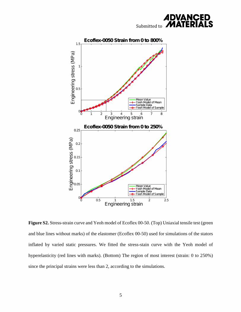
by importing the designed geometry of the stators. Figure S2 shows the engineering stress-strain
curves of Ecoflex 00-50 from tensile data of five degassed and cured samples. The green curve is
plotted with the mean values of the five samples, and the blue curve is the stress-strain curve of
one of these five samples. We considered the material as a hyper-elastic solid and fitted the test
data to the Yeoh hyper-elastic material model with the module for curve fitting in ANSYS
Workbench, and then plotted the curves in MATLAB (shown as red curves with marks). The strain
energy density of nearly-incompressible Yeoh model (also shown by Mosadegh, et al.[14]) has the
following form:
(2)
where , , and is the deformation gradient and and are the
materials parameters. When we set N = 3 (3rd-ordered Yeoh model), the curve fitting module in
ANSYS calculated the parameters. For the mean data of the five samples, we have ,
, , . For the data of the sample used in this study,
the parameters were , , , .
U = Ci0I
1-3( )
i
i=1
N
å +1
Di
J -1( )2i
i=1
N
å
I1= tr dev FF( )
Té
ëêù
ûúJ = det F( ) F C
i0Di
C10
=1.90´10-2
C20
= 9.0´10-4 C30
= -4.75´10-6 D1= D
2= D
3= 0
C10
=1.75´10-2 C20
= 6.70´10-4 C30
= -2.65´10-6 D1= D
2= D
3= 0
Submitted to
5
Figure S2. Stress-strain curve and Yeoh model of Ecoflex 00-50. (Top) Uniaxial tensile test (green
and blue lines without marks) of the elastomer (Ecoflex 00-50) used for simulations of the stators
inflated by varied static pressures. We fitted the stress-stain curve with the Yeoh model of
hyperelasticity (red lines with marks). (Bottom) The region of most interest (strain: 0 to 250%)
since the principal strains were less than 2, according to the simulations.

Submitted to
6
By varying the applied pressure inside of embedded bladders, we witnessed the deformation of
the bladders and the estimated principal strains shown in Figure S3 b, d. According to the results
of the simulations, the maximum principal strain of the inflated bladders was 2, which means the
region of most interest on the curve is the strain of 0-200% indicated in Figure S2 (Bottom).
Simulated and Experimental Behavior of Inflation with Static Internal Pressures
We performed 3D finite element analyses for both types of actuator with Mechanical APDL
R15 (ANSYS Inc., PA). There were 50600 and 58292 elements in the mesh for Type 1 and Type
2 actuators, respectively. By using a hex-dominant method, we were able to create combined types
of element, including Hex20, Tet10, Wed15, and Pyr13. In both models, 96% of the total elements
were comprised of Hex20 elements. There was a fixed-support boundary condition on the inner
circumferential surface for Type 1 actuator and the outer circumferential surface for Type 2
actuator, respectively. As for the material model, we adopted a three-parameter Yeoh model for
the hyperelastic material (Ecoflex 50) in a similar fashion to the work completed by Mosadegh, et
al.[14] (Figure S2). The load applied on the bladders gradually increased from 0 psi to 9 psi in both
models.
Given a specified static internal pressure, the simulations showed the volumes of a subgroup
of bladders and their corresponding maximum principal strains when pressurized. The maximum
principal strain (~200%) did not exceed the maximum strain at break of the Ecoflex 00-50 (980%)
provided by the manufacturer, which means the bladders should not have yielded at an applied
pressure up to 62.1 kPa. We then validated the FEA qualitatively by comparing the deformation
of the stators caused by the applied pressures with experimentally acquired images (Figure S3 b,
d). For the stators consisting of two separate bonded layers, these experiments also demonstrated
that the adhesion between bonded parts was generally sufficient for pressures associated with
Submitted to
7
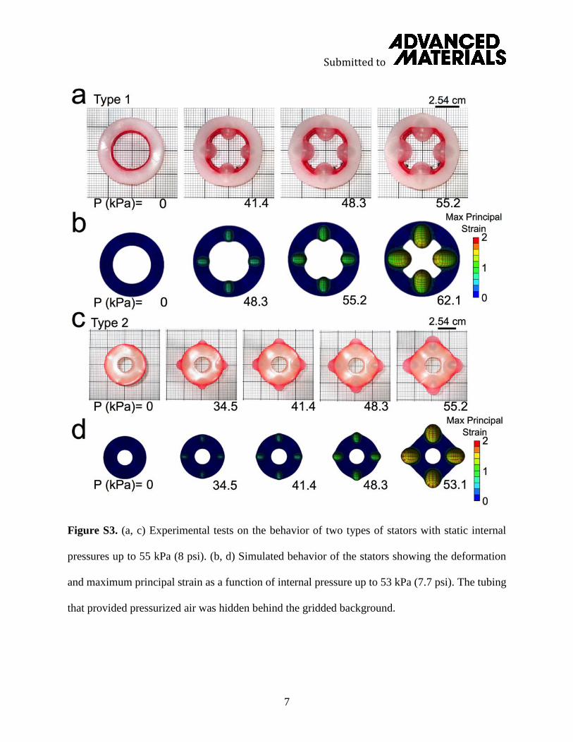
Figure S3. (a, c) Experimental tests on the behavior of two types of stators with static internal
pressures up to 55 kPa (8 psi). (b, d) Simulated behavior of the stators showing the deformation
and maximum principal strain as a function of internal pressure up to 53 kPa (7.7 psi). The tubing
that provided pressurized air was hidden behind the gridded background.

Submitted to
8
rotation. That said, failures did occur occasionally at higher pressures than 62.1 kPa due to
delamination after low-cycle fatiguing.
In addition, the experimentally acquired images of the stators with one subgroup of bladders
inflated (Figure S3 a, c) suggested that the simulated results were similar to the experiments at
corresponding pressures. According to Figure S3 a, c, increasing the static internal pressure
enlarged the deformation of the bladders. With 41.4 kPa (6 psi) of applied pressure, the
deformation was not conspicuous. A large expansion of the bladders occurred when the static
internal pressure was between 48.3 kPa (7 psi) and 55.2 kPa (8 psi). We hypothesize that the large
deformation of the embedded bladders appeared to force the rotor to turn. The rapid expansions
with their sudden releases of kinetic energy also facilitated the forcing of the actuators through
their metastable states. Furthermore, the experiments revealed that the increasingly enlarged
deformation of the inflated bladders (after passing through the snap-through instability) did not
show any delamination between the two layers of the stator.
Programmable Pneumatic System and Speed Control
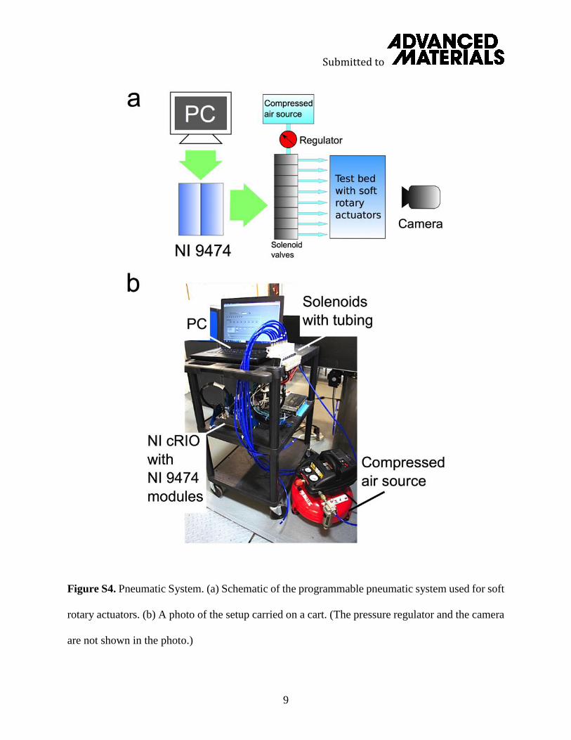
We built a programmable pneumatic system (Figure S4) to control and direct pressurized air
to the inflatable bladders in the rotary actuators. A Type 700 high-flow pressure regulator
(ControlAir Inc.) regulated the pressure for the inflation, with a pressure gauge (Ashcroft, Inc.)
monitoring the pressure. To control the timing of the solenoids accurately, we used an FPGA-
based NI cRIO-9076 with two 8-channel, 1 s high-speed digital output modules NI 9474 from
National Instruments. The two NI 9474 modules provided 16 digital outputs that could drive up
to 16 directional control (3-port, 2-position) solenoid valves (VKF Series, SMC Inc.). The software
is similar and the LabVIEW Virtual Instruments are nearly identical to the pneumatic system
employed for multi-gait, reconfigurable, and camouflaging robots[6,7]. This system allows us not
Submitted to
9
Figure S4. Pneumatic System. (a) Schematic of the programmable pneumatic system used for soft
rotary actuators. (b) A photo of the setup carried on a cart. (The pressure regulator and the camera
are not shown in the photo.)
Submitted to
10
only to control manually each valve through the keyboard but also to import a spreadsheet with
the information of the control pattern (timing and a specific sequence) of the actuation of the valves
and achieve the automatic control.
Once assembled, inflation of the bladders in the stator caused the rotor to turn. To reduce the
fatigue and large deformation caused by high, alternating pressure-based loads on the bladders,
and to avoid yielding of the material, we inflated the bladders to a constant volume – the minimum
inflation that made the rotors turn consistently. With the pneumatic system equipped with the
specified solenoid valves, pressure regulator, and tubing, we changed the flow rate of the
pressurized air filling in the bladders by regulating the pressure with the regulator. Higher flow
rates of air induced higher inflation rate of the bladders, thus, a shorter time was needed to
inflate each subgroup of bladders to the minimum volume required. While this minimum volume
had an associated static internal pressure, the use of a standard regulator meant that we would
typically set a pressure on the regulator that might otherwise cause a larger static deformation. In
this way, the bladders inflated quickly to the minimum volume when a solenoid then cut off the
airflow before the actual internal pressure in the bladders reached the pressure set on the regulator.
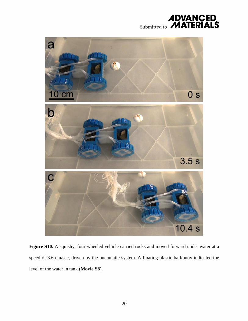
Estimating Deflation Times with a High-Speed Camera
As discussed in the main text, increasing pressure lead to a higher rotational speed due to an
increased inflation time (Equation 1). However, the deflation times remained relatively
consistent for a given volume of the inflated bladders. To estimate the rotational speed of a rotary
actuator, we used a modest high-speed camera (Figure S5, Movie S1).
Instead of sending command signals (Figure 2a) to the valves, we manually open a valve for
one subgroup of bladders with a keyboard. Starting from a very low pressure, we gradually
tinflation
Submitted to
11
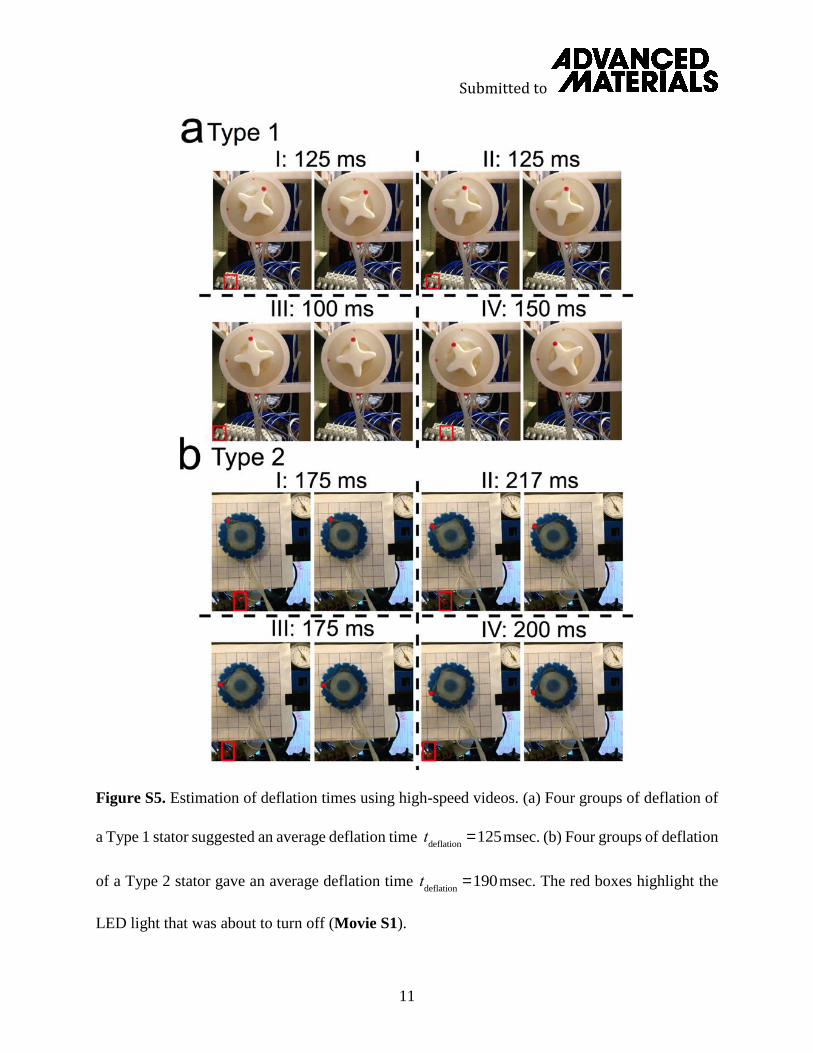
Figure S5. Estimation of deflation times using high-speed videos. (a) Four groups of deflation of
a Type 1 stator suggested an average deflation time msec. (b) Four groups of deflation
of a Type 2 stator gave an average deflation time msec. The red boxes highlight the
LED light that was about to turn off (Movie S1).
tdeflation
=125
tdeflation
=190
Submitted to
12
increased the set pressure on the regulator, until the inflation of these bladders just reached the
minimum that could enable a rotation from this subgroup to an adjacent subgroup. Thus, the
pressure on the regulator (~ 48.3 kPa (7 psi)) reflected the static internal pressure of these inflated
bladders. And then, we closed the valve to exhaust the bladders. By observing and counting
the frames (acquired from high-speed videos) between closing a valve (indicated by the LED lights
on the valves) and a complete exhaustion of a group of bladders, we were able to calculate a
deflation time for this group. We did nine groups of experiments for Type 1 actuators and four
groups of experiments for Type 2 actuators.
Figure S5 summarizes four groups of experiments for each type of actuator. For each group,
we picked the frame showing the LED light on a valve as it was about to turn off and the frame
showing the shape of the stator when completely restored. The speed of the camera we used was
120 frames/sec. By counting the number of total frames between the two selected frames, we were
able to calculate the deflation time . We indicated the calculated for each experiment
in the figure. The average for Type 1 was 125 msec (130 msec with nine experiments), and
the average for Type 2 was 190 msec.
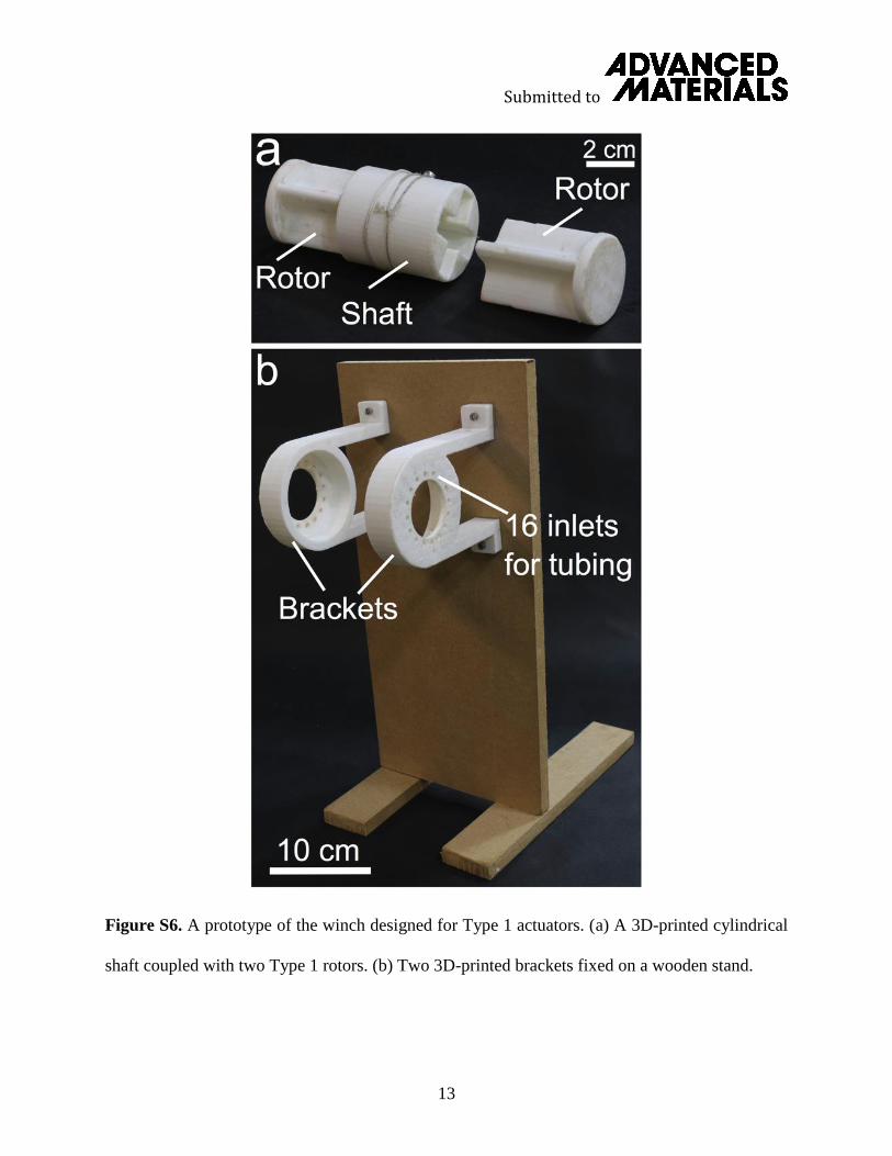
Prototyping the winch with Type 1 Actuators
In order to produce a “torque-speed” curve for Type 1 actuators, we designed and prototyped
a winch equipped with Type 1 actuators (Figure S6). A 3D-printed cylindrical shaft coupled two
Type 1 rotors through a cross-shaped hole. A string attached to the shaft carried external loads for
characterization (Figure S6 a). Two 3D-printed brackets held the internal portions of the two
stators, and the tubing on the stators easily passed though the 16 small inlets on each bracket
tdeflation
tdeflation
tdeflation
tdeflation
Submitted to
13
Figure S6. A prototype of the winch designed for Type 1 actuators. (a) A 3D-printed cylindrical
shaft coupled with two Type 1 rotors. (b) Two 3D-printed brackets fixed on a wooden stand.
Submitted to
14
(Figure S6 b). A stand made of wooden boards attached with the brackets formed the whole
frame of the winch. After equipping the stators in the brackets and inserting the shaft into the
stators, we profiled the “torque-speed” relationship for a Type 1 actuator, by varying the load
added onto the winch (see Figure 3c).
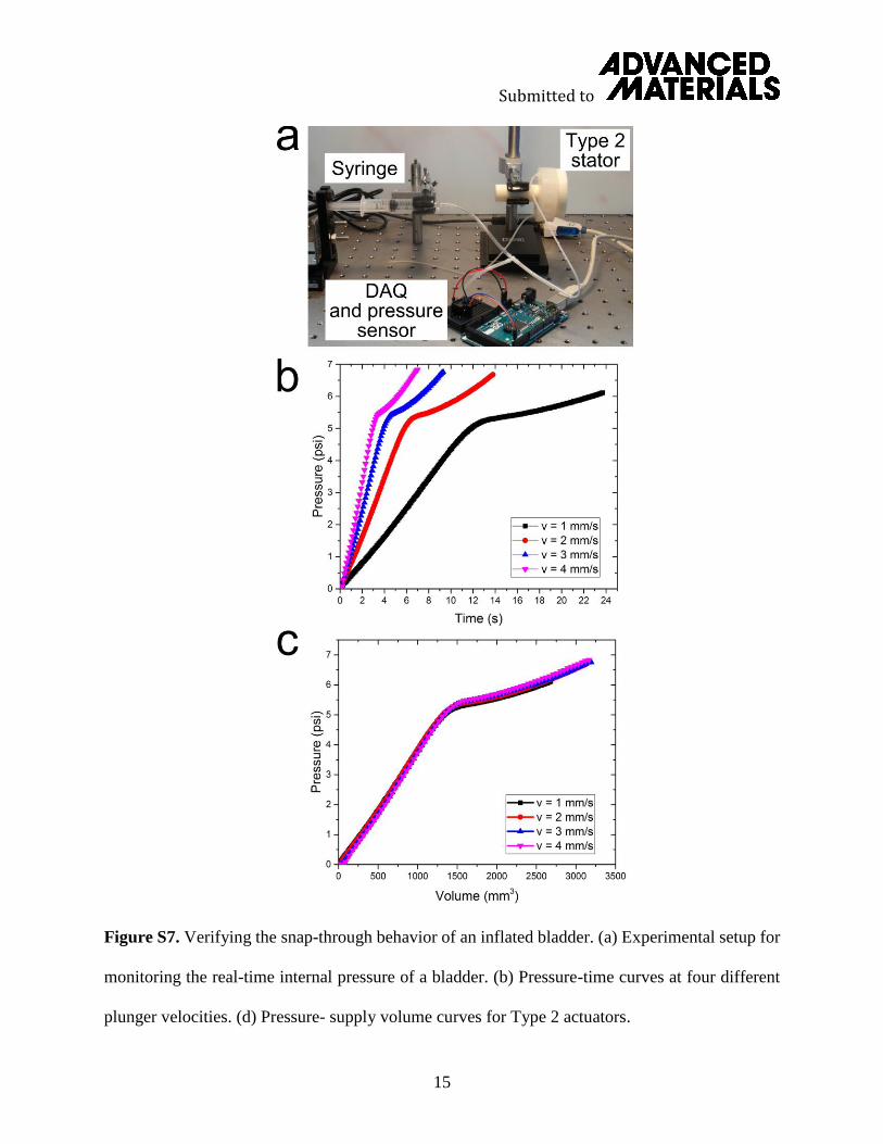
Snap-Through Instability of a Pressurized Bladder
To provide the direct evidence for the snap-through instability of a bladder with a release of
kinetic energy, we monitored the real-time internal pressure in the bladder corresponding to the
change in supplied volume. We used a syringe pump as the air supply, and monitored the internal
pressure with a pressure sensor (ASDX, Honeywell) and an Arduino-based (Arduino, Mega) data
acquisition (DAQ) system (Figure S7 a). We observed the inflation of a Type 2 bladder. Pumping
the bladder with a syringe at four plunger velocities (v = 1, 2, 3, 4 mm/s), we plotted four pressure
– time curves (Figure S7 b). The supplied volume was simply the product of the syringe’s
displacement and the internal cross-sectional area (113 mm2 from an inner diameter of 6 mm) of
the syringe. In Figure S7 c, we noticed there was a significant non-linear change in the pressure-
volume relationship at a supplied volume of ~1500 mm3. This change in the slope of the curve is
characteristic of an inflatable elastomeric bladder with a snap-through instability[34–37].
A Winch with a Soft Gripper
We attached an elastomeric gripper (16.4 grams) with embedded PneuNets[4] on the winch,
showing that it was possible to combine the rotary actuators with a soft gripper to build a multi-
functional soft system (Movie S3). With a 3D printer (FlashForge Creator) producing the molds,
we fabricated a soft robotic gripper from Ecoflex 00-30 (Smooth-On Inc.) for the strain-limiting
layer, and Mold Star 15 (Smooth-On Inc.) for the inextensible layer. Silicone tubing (independent
Submitted to
15
Figure S7. Verifying the snap-through behavior of an inflated bladder. (a) Experimental setup for
monitoring the real-time internal pressure of a bladder. (b) Pressure-time curves at four different
plunger velocities. (d) Pressure- supply volume curves for Type 2 actuators.

Submitted to
16
of the pneumatic system) supplied the compressed air to the gripper through a manually controlled
syringe.
The external torque on the winch was Nm, which was estimated with the mass of the
gripper. Thus, the torque acting on each stator was Nm. Starting at the top (Height 22
cm), the winch lowered the gripper at a rate of 1.7 cm/sec (Figure S8 a-b). After the shaft turned
through 11 steps, the gripper reached the position (Height 13 cm) shown in Figure S8 b. When
the gripper contacted the object, we actuated the gripper to grasp the object by compressing the air
into the embedded PneuNets through a syringe. Then, the winch started to lift the gripped object.
The external torque on the winch increased to Nm due to the mass of the object. In order
for the winch to carry heavier load at the same speed, we increased the pressure slightly on the
regulator. In Figure S8 c-d (Height: from 0 to 14 cm), the winch raised the gripper and the object
at a rate of 1.6 cm/sec, turning in around 17 steps.
A Squishy, Two-Wheeled Vehicle
The basic design consisted of an elastomeric body, two axles made of Mold Star 30 (Smooth-On
Inc.), and two Type 2 actuators (Figure S9 a). In case the parallel-wheeled device would lose its
balance – similar to a unicycle – and not be able to function as a real vehicle, we attached a
paperclip to each end of the body as supports (Figure S9 b). Directed by the designed command
pattern for each wheel, the two-wheeled vehicle demonstrated its ability to navigate around an
obstacle (Figure S9 c-h, Movie S4). This vehicle presented the capability of going forward, going
backward, and turning. The set pressure on the regulator was 86.2 kPa (12.5 psi) and the
corresponding inflation time was approximately 180 msec. Based on Equation 1, the rotational
3.2´10-3
1.6´10-3
9.2´10-3

Submitted to
17
Figure S8. A winch equipped with two Type 1 stators acting in parallel and a soft gripper (16.4
grams) that could grasp and lift an object weighted 30.7 grams. (a) The gripper started at the top.
(b) The winch lowered the gripper at a speed of 1.6 cm/sec. (11 steps of the rotor). (c) The gripper
inflated and grasped the object. (d) The winch raised the gripper and grasped object at a rate of 1.6
cm/sec (17 steps of the rotor) (Movie S3).

Submitted to
18
Figure S9. (a) Design of the squishy two-wheeled vehicle, (b) The highlighted pieces are two
paperclips used to balance the vehicle. (c-h) To navigate around an obstacle in its way, the two-
wheeled soft vehicle moved forward, stopped, moved backward, made a left turn, went forward,
turned back to straight and then went forward. The arrows indicate the moving directions of the
vehicle (Movie S4).
Submitted to
19
speed was 10.3 RPM. Considering the diameter of the wheels was 9.2 cm, the speed of the two
wheeled vehicle was 4.9 cm/s.
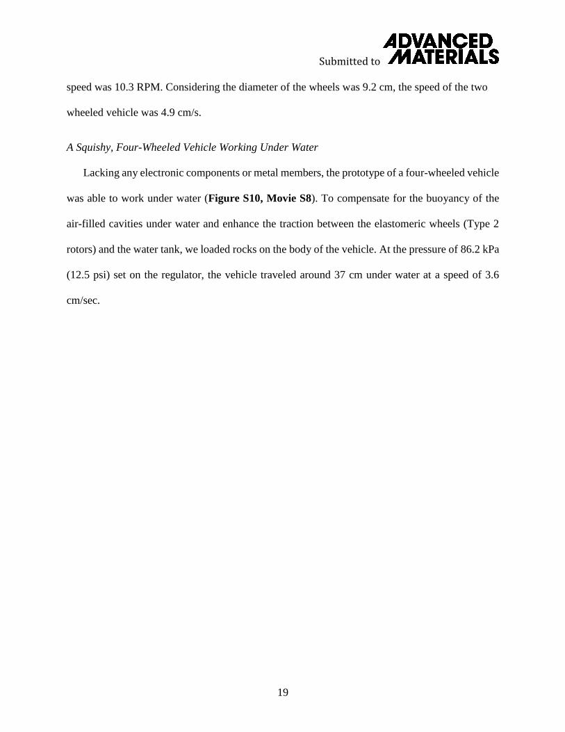
A Squishy, Four-Wheeled Vehicle Working Under Water
Lacking any electronic components or metal members, the prototype of a four-wheeled vehicle
was able to work under water (Figure S10, Movie S8). To compensate for the buoyancy of the
air-filled cavities under water and enhance the traction between the elastomeric wheels (Type 2
rotors) and the water tank, we loaded rocks on the body of the vehicle. At the pressure of 86.2 kPa
(12.5 psi) set on the regulator, the vehicle traveled around 37 cm under water at a speed of 3.6
cm/sec.
Submitted to
20
Figure S10. A squishy, four-wheeled vehicle carried rocks and moved forward under water at a
speed of 3.6 cm/sec, driven by the pneumatic system. A floating plastic ball/buoy indicated the
level of the water in tank (Movie S8).
Submitted to
21
Movie S1. Experiments to estimate the deflation time for Type 1 and Type 2 actuators (see Figure
S5).
Movie S2. A Type 2 actuator rotating at ~13 RPM.

Submitted to
22
Movie S3. A winch equipped with two Type 1 stators acting in parallel to lower and lift a soft
gripper (see Figure S8).
Movie S4. A two-wheeled soft vehicle navigating around an obstacle (see Figure S9).
Submitted to
23
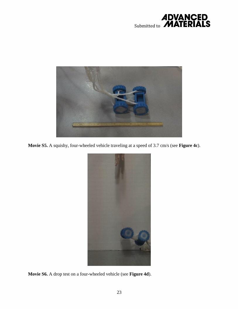
Movie S5. A squishy, four-wheeled vehicle traveling at a speed of 3.7 cm/s (see Figure 4c).
Movie S6. A drop test on a four-wheeled vehicle (see Figure 4d).

Submitted to
24
Movie S7. A squishy, four-wheeled vehicle navigating a rocky terrain with a puddle in its path
(see Figure 4e).
Movie S8. A four-wheeled soft vehicle working under water (see Figure S10).

Submitted to
25
Movie S9. Inflation of a bladder in a Type 2 stator with a syringe pump. The velocity of the plunger
is 3mm/s. (see Figure S7, a)


