Robust Blind Carrier Frequency Offset EstimationAlgorithm for OFDM Systems
Arunprakash Jayaprakash1 • G Ramachandra Reddy1
Published online: 3 September 2016� Springer Science+Business Media New York 2016
Abstract In this paper, a joint covariance power fitting and phase based blind estimation
method for carrier frequency offset (CFO) is proposed for orthogonal frequency division
multiplexing (OFDM) systems using constant modulus constellations. Based on the
assumption that the channel varies slowly within two adjacent OFDM symbols, the
influence of the channel on corresponding covariance values and phase of the two OFDM
symbols will be the same. Utilizing this, a robust method is formulated based on covari-
ance power fitting criterion and phase information between two nearby OFDM symbols.
The mean square error and bit-error-rate performance of the proposed estimation method is
compared with that of the prominent conventional estimation schemes under noisy mul-
tipath channels with high delay spreads and Doppler spreads. Based on Monte Carlo
simulations, it is shown that the proposed method is robust under different channel con-
ditions and provides more accurate CFO estimates.
Keywords Blind estimation � Carrier frequency offset � Frequency selective � Orthogonalfrequency division multiplexing (OFDM)
1 Introduction
Orthogonal frequency division multiplexing (OFDM) has been the popular modulation
technique for high data-rate wireless transmission over multipath frequency selective
channels [1]. It is employed in different wireless standards like digital audio [2] and video
broadcasting [3], wireless local area network standards IEEE 802.11a/g [4], 4G LTE [5]
etc. The popularity of OFDM is because of its high spectral efficiency due to the mutually
orthogonal sub-carriers. Even if the subcarriers are closely spaced without any guard
& Arunprakash [email protected]
1 School of Electronics Engineering, VIT Univeristy, Vellore, Tamil Nadu 632014, India
123
Wireless Pers Commun (2017) 94:777–791DOI 10.1007/s11277-016-3650-9

bands, there will not be any inter subcarrier interference. But any mismatch between the
transmitted and received frequencies distorts the orthogonality of the subcarriers. This loss
of orthogonality happens under doubly dispersive channels in which the impulse response
of the channel is time variant and undergoes time spreading. A relative velocity between
the transmitter and receiver introduces a Doppler shift in the transmitted frequency and the
data is received at a different subcarrier frequency. The difference between the transmitted
and received frequency, known as carrier frequency offset (CFO), distorts the orthogo-
nality between the subcarriers. The CFO can also be induced due to a dissimilarity in local
oscillator frequencies of the transmitter and the receiver. These result in the interference of
one subcarrier with one or more of its neighboring subcarriers which is known as inter
carrier interference (ICI). Therefore, accurate estimation of CFO has been an active area of
research.
A variety of blind CFO estimation schemes for constant magnitude modulations are
studied in the literature. A blind CFO estimation scheme for OFDM is proposed in [6],
where the cost function is formulated based on a kurtosis type criterion. Another CFO
estimation scheme is presented in [7] where CFO is found out by utilizing the variance of
the interference which occurs owing to the loss in orthogonality between the subcarriers. A
non-supervised CFO estimation method called PDE-F method is proposed in [8]. In this
method, the channel effect upon two adjacent subcarriers in the same OFDM symbol is
assumed to be non-varying. Hence, CFO is estimated by minimizing a cost function
formulated based on the power difference between received samples corresponding to two
the adjacent subcarriers. The accuracy of estimation by PDE-F scheme depends on the time
dispersion of the channel impulse response and its performance gets degraded under highly
frequency selective channels. In [9], a robust non-supervised CFO estimation procedure
called PDE-T method is proposed, under the assumption that the channel can be highly
time dipsersive and frequency selective but remains almost invariant at consecutive symbol
time instants. Here, the objective function is formulated upon the sum of power difference
between demodulated symbols on similar subcarrier indices of two adjacent OFDM
symbols. In [10], CFO is evaluated by maximizing an objective function formulated as the
product of the magnitude of the demodulated data on similar subcarrier indices of nearby
OFDM symbols. In [11], CFO is estimated by utilizing out-of band elements of covariance
matrix which is generated using a single OFDM symbol. The covariance based technique
requires information about the length of the channel for accurate formulation of the cost
function. Moreover, the number of out-of-band elements of the covariance matrix reduces
with an increase in the length of the channel, which affects the estimation accuracy of the
method. An accurate iterative CFO estimation scheme based on modified Viterbi and
Viterbi (VAV) algorithm is proposed in [12]. In this method, CFO is estimated from the
difference in phase information between consecutive OFDM symbols which are raised to
the power of modulation order of the modulated symbols. The angle based technique
exhibits good performance in terms of estimation accuracy than the conventional methods,
but the range of fractional CFO values which can be precisely estimated decreases with an
increase in the modulation order. A modified transmission scheme using two different
constellation sizes within the OFDM symbol is also proposed in [12] to improve the
estimation range of iterative VAV scheme, but at the cost of reduced data throughput.
In the present study, we present a new non-supervised CFO estimation technique for
OFDM system using constant magnitude constellations. The CFO is estimated utilizing the
power invariance of covariance fitting values as well as the phase information in the
demodulated OFDM symbols so that the range of CFO estimation is improved at the same
time providing better CFO estimates than the conventional counterparts. The performance
778 A. Jayaprakash, G. R. Reddy
123
of the proposed covariance fitting method is analyzed and compared with other conven-
tional methods in terms of mean square error (MSE) and bit error rate (BER) for doubly
dispersive channel conditions.
The paper is structured as follows. Section 2 is devoted to the system model for OFDM
symbol affected with CFO. The formulation of the proposed method is presented in
Sect. 3. The numerical results and analysis are provided in Sect. 4. Finally, the paper is
concluded in Sect. 5.
In this paper, vectors are represented with lower case boldface letters, while matrices
are denoted by upper case boldface letters. Scalar quantities are indicated with normal
letters. The notations j � j and ð�Þ� denote respectively the modulus and complex conjugate
operations. The notation k � k represents Eucledian norm of a vector. The notations Ref�gand Imf�g represent the real part and imaginary part of a variable respectively.
2 System Model for OFDM Symbol Affected with CFO
Consider a fully loaded OFDM system consisting of N complex data symbols modulated
onto N orthogonal subcarriers. The complex source symbols are uniformly drawn from a
constant modulus constellation like M-ary phase shift keying (PSK). Consider a complex
data vector bm ¼ bmð0Þ; bmð1Þ; . . .; bmðN � 1Þ½ �T which is used for the generation of mth
OFDM symbol block. The mth OFDM symbol xm ¼ xmð0Þ; xmð1Þ; . . .; xmðN � 1Þ½ �T is
obtained by [9]
xmðnÞ ¼1ffiffiffiffi
Np
X
N�1
k¼0
bmðkÞej2pknN; n ¼ 0; 1; . . .;N � 1 ð1Þ
If F represents the inverse discrete Fourier transform matrix, xm ¼ Fbm. In order to avoid
inter symbol interference (ISI) between two successive OFDM symbols, a guard time
called cyclic prefix is included at the beginning of each symbol, which is filled with the last
Np values of xm, where Np corresponds to a time interval greater than the delay spread of
the channel. Due to the presence of cyclic prefix the transmitted data at each subcarrier can
be recovered by dividing the received data with the frequency response of the channel at
that subcarrier.
If the channel frequency response matrix corresponding to the mth symbol index is
represented as Hm, the mth time domain OFDM symbol affected by channel is obtained as
FHmbm. Hm is a diagonal matrix which consists of the Fourier transform of the time
domain channel taps evaluated at the subcarriers. Let e represent the CFO value normalized
by subcarrier spacing. The received OFDM symbol affected by CFO and channel under the
assumption of noise free transmission is given in [9]
ym ¼ ej2pemðNþNpÞ
N HeFHmbm ð2Þ
where He is a diagonal matrix given by
He ¼ diag 1; e2peN�1; e
2peN�2; . . .; e
2peN�ðN�1Þ
h iT� �
The scalar term, which is the first exponential term in (2) is dependent on m, which
represents the common phase shift. Let dm ¼ dmð0Þ; dmð1Þ; . . .; dmðN � 1Þ½ �T¼ FHmbm
Robust Blind Carrier Frequency Offset... 779
123
represents the channel affected OFDM symbol and the effect of CFO is denoted by
Um ¼ ej2pemðNþNpÞ
N He. Hence the received symbol reduces to
ym ¼ Umdm ð3Þ
dm ¼ U�1m ym ð4Þ
If the estimated CFO value is represented as e, the OFDM symbol after the correction of
CFO is [9]
dm ¼ e�j2pemðNþNpÞ
N H�eym ð5Þ
3 Proposed CFO Estimation Algorithm for OFDM Systems
Different CFO estimators presented in [9–13] for constant modulus constellation are based
upon the assumption that the channel parameters are invariant between the adjacent OFDM
symbols. The basic principle behind these estimators is that for constant modulus con-
stellations, the magnitude of the demodulated symbols will be same as the magnitude of
the channel’s frequency response if the CFO is compensated accurately [9]. i.e.
FHdm�
�
�
� ¼ Hmj j bmj j ¼ Hmj j. Owing to the invariance of the channel between two nearby
OFDM symbols, FHdm�
�
�
� ¼ FHdmþ1
�
�
�
�. This happens because, the magnitude of the data
symbols bmj j ¼ bmþ1j j ¼ 1. This is true for all subcarriers, if and only if, CFO is perfectly
estimated and corrected [9]. However, the present study utilizes the invariance of the
covariance matrix values and the phase information of two adjacent OFDM symbols.
Let ðeÞ be a trial value of CFO used for compensation and the corrected OFDM signal
be represented as a vector dm;e ¼ dm;eð0Þ; dm;eð1Þ; . . .; dm;eðN � 1Þ� �T
given by [9]
dm;e ¼ e�j2pemðNþNpÞ
N H�eym ð6Þ
A matrix, Dm;e is formed by stacking circularly shifted dm;e column vectors. i.e.,
Dm;e ¼
dm;eð0Þ dm;eð1Þ . . . dm;eðN � 2Þ dm;eðN � 1Þdm;eð1Þ dm;eð2Þ . . . dm;eðN � 1Þ dm;eð0Þ
..
. ... . .
. ... ..
.
dm;eðN � 2Þ dm;eðN � 1Þ . . . dm;eðN � 4Þ dm;eðN � 3Þdm;eðN � 1Þ dm;eð0Þ . . . dm;eðN � 3Þ dm;eðN � 2Þ
2
6
6
6
6
6
6
6
6
4
3
7
7
7
7
7
7
7
7
5
ð7Þ
The covariance matrix corresponding to m-th OFDM symbol is obtained from Dm;e as [11]
Rm;e ¼1
NDm;eD
Hm;e ð8Þ
In [11], it is established that, the covariance matrix obtained by the cyclic shift method
depends solely on the channel properties for constant magnitude constellations, if CFO
compensation is perfect. Therefore, two adjacent OFDM symbols should correspond to a
single covariance matrix since the channel characteristics remain unaltered between them.
Moreover, the covariance matrix is Hermitian Toeplitz which can be represnted as [11]
780 A. Jayaprakash, G. R. Reddy
123

Rm;e ¼ Toeplitz rm;e�
ð9Þ
where rm;e ¼ rm;eð0Þ; rm;eð1Þ; . . .; rm;eðN � 2Þ; rm;eðN � 1Þ� �T
represents the first column of
the covariance matrix. Since the elements in the Rm;e are repeating, the first column vector
rm;e is sufficient for the formulation of cost function. From (7) and (8), rm;e is obtained as
rm;e ¼1
NDm;ed
�m;e ð10Þ
If the channel characteristics remains unchanged between L consecutive OFDM symbols,
the objective function to be minimized is formulated as
JðeÞ ¼X
L�1
m¼1
rm;e � rmþ1;e
2 ð11Þ
where rm;e and rmþ1;e correspond to the first column vectors of the covariance matrices of
the mth and (m?1)th OFDM symbol respectively.
The estimate of actual CFO e, represented as be, is obtained by minimizing the objective
function J eð Þ represented in (11).
be ¼ arg mine2 �0:5;0:5ð Þ
J eð Þ ð12Þ
The objective function given by (11) follows the shape of a sinusoid which is similar to that
in [9] and hence the optimum value of CFO can be obtained by a three point substitution
method instead of going for complex exhaustive search methods. The cost function can be
represented as [11]
J eð Þ ¼ A cos 2p e� eð Þð Þ � A ð13Þ
Here A is independent of CFO. Three different values of e ¼ 0; 0:25 and -0.25 are
substituted in (13). The optimum value of e is obtained as [11]
be ¼
1
2ptan�1 b=að Þ for a� 0
1
2ptan�1 b=að Þ þ 1
2for a\0 and b� 0
1
2ptan�1 b=að Þ � 1
2for a\0 and b� 0
8
>
>
>
>
>
<
>
>
>
>
>
:
ð14Þ
where a ¼ J 0:25ð Þ þ J �0:25ð Þð Þ=2ð Þ � J 0ð Þf g and b ¼ J 0:25ð Þ � J �0:25ð Þð Þ=2ð Þf g.The problem formulation was carried out in the absence of noise. Due to the presence of
additive white Gaussian noise, there will be a small error in estimation. The residual error
de ¼ e� be will be very small. When CFO is corrected using (5), the vector containing the
channel affected demodulated source symbols €dm ¼ €dmð0Þ; €dmð1Þ; . . .; €dmðN � 1Þ� �T
is
obtained by correcting the CFO using the estimated CFO be as in (5) and applying inverse
FFT which is represented in [9] as
€dm ¼ FHe�j2pbemðNþNpÞ
N H�eym ð15Þ
Since be ¼ e� de, (15) is reduced to
Robust Blind Carrier Frequency Offset... 781
123
€dm ¼ FHej2pðdeÞm NþNpð Þ
N HdeFHmbm ð16Þ
Similarly, the compensated vector for ðmþ 1Þ-th symbol instant is given as
€dmþ1 ¼ FHe�j2pbe mþ1ð ÞðNþNpÞ
N H�eymþ1 ð17Þ
€dmþ1 ¼ FHej2pðdeÞ mþ1ð Þ NþNpð Þ
N HdeFHmþ1bmþ1 ð18Þ
From (16) and (18), it may be inferred that the elements €dmðnÞ and €dmþ1ðnÞ, correspondingto the same subcarriers in the vectors €dm and €dmþ1 have similar phase except the scalar
term involving the residual CFO value and the phase of source symbols drawn from M-ary
PSK constellations. If the elements in both the vectors are raised to the power of M, the
angle of the M-PSK modulated symbols reduces to zero and the phase difference between
the elements in both the vectors solely depend on the residual CFO. Here, since the residual
CFO is small, even though the symbols are raised to the power of M, phase ambiguity is
not observed at higher M values. Therefore the CFO, de can be accurately estimated in a
single step as
bde ¼N
2pM N þ NPð Þ angleX
L�1
m¼1
X
N�1
n¼0
dmþ1ðnÞd�mðnÞ� M
( )
ð19Þ
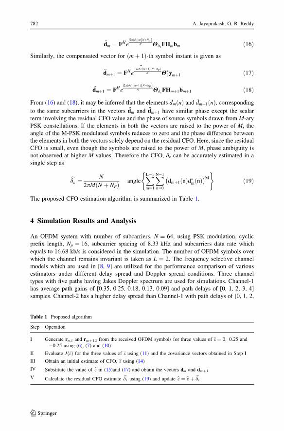
The proposed CFO estimation algorithm is summarized in Table 1.
4 Simulation Results and Analysis
An OFDM system with number of subcarriers, N = 64, using PSK modulation, cyclic
prefix length, Np ¼ 16, subcarrier spacing of 8.33 kHz and subcarriers data rate which
equals to 16.68 kb/s is considered in the simulation. The number of OFDM symbols over
which the channel remains invariant is taken as L = 2. The frequency selective channel
models which are used in [8, 9] are utilized for the performance comparison of various
estimators under different delay spread and Doppler spread conditions. Three channel
types with five paths having Jakes Doppler spectrum are used for simulations. Channel-1
has average path gains of [0.35, 0.25, 0.18, 0.13, 0.09] and path delays of [0, 1, 2, 3, 4]
samples. Channel-2 has a higher delay spread than Channel-1 with path delays of [0, 1, 2,
Table 1 Proposed algorithm
Step Operation
I Generate rm;e and rmþ 1;e from the received OFDM symbols for three values of e ¼ 0; 0:25 and
�0:25 using (6), (7) and (10)
II Evaluate JðeÞ for the three values of e using (11) and the covariance vectors obtained in Step I
III Obtain an initial estimate of CFO, be using (14)
IV Substitute the value of be in (15)and (17) and obtain the vectors €dm and €dmþ 1
V Calculate the residual CFO estimate bde using (19) and update be ¼ be þ bde
782 A. Jayaprakash, G. R. Reddy
123
6, 11] and average path gains of [0.34, 0.28, 0.23, 0.11, 0.04]. Channel-3 has a much higher
delay spread with path delays of [0, 4, 8, 12] samples and uniform average path gains of
[0.25, 0.25, 0.25, 0.25]. The proposed covariance and phase based method is compared
with the estimators in [9] and [11] in terms of MSE and BER for various channel con-
ditions under the effect of AWGN noise using Monte Carlo simulations. The MSE per-
formance is obtained through K = 10000 estimations of CFO and averaging them. i.e.
MSE ¼ 1K
PKk¼ 1 e� bekð Þ2
n o
where e is the true value of CFO and bek is the estimated value
of CFO for kth iteration. The CFO value is kept constant over L = 2 OFDM symbols and
changes randomly from one pair of OFDM symbols to the other. The PDE-T based [9]
method and covariance based method [11] are the state-of-the-art blind carrier frequency
offset frequency estimation methods for constant modulus constellations. PDE-T method is
proved to be better than the other power difference based estimators [9]. The VAV
algorithm based method [12] is another blind CFO estimation method but, unlike the other
power difference based estimators, the range of CFO estimation depends on the constel-
lation size, computational complexity is comparatively larger and is iterative. The
covariance based method is proved to be better than PDE-T based method with similar
computational complexity, which is investigated in [11] under certain channel conditions.
But its performance can vary based on the length of the channel. Hence, the two prominent
blind CFO estimation methods are considered as benchmark for comparison. In order to
analyze the robustness of each algorithm under different frequency selective conditions,
the various estimators are analyzed under the three Rayleigh fading channels with zero
Doppler shift. The MSE versus signal to noise ratio (SNR) variation and the BER versus
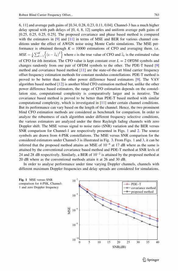
SNR comparison for Channel-1 are respectively presented in Figs. 1 and 2. The source
symbols are drawn from 4-PSK constellations. The MSE versus SNR comparison for the
considered estimators under Channel-3 is illustrated in Fig. 3. From Figs. 1 and 3, it can be
inferred that the proposed method attains an MSE of 10�6 at 17 dB where as the same is
attained by the conventional covariance based method and PDE-T method at SNR levls of
24 and 28 dB respectively. Similarly, a BER of 10�2 is attained by the proposed method at
20 dB where as the conventional methods attain it at 26 and 30 dB.
In order to analyse performance under time varying Doppler channels, channels with
different maximum Doppler frequencies and delay spreads are considered for simulations.
0 5 10 15 20 25 30 35 4010−10
10−8
10−6
10−4
10−2
SNR(dB)
MSE
PDE−Tcovariance methodproposed method
Fig. 1 MSE versus SNRcomparison for 4-PSK, Channel-1 and zero Doppler frequency
Robust Blind Carrier Frequency Offset... 783
123

The Doppler frequencies are normalized with the subcarrier bandwidths. The MSE versus
SNR plots for maximum Doppler frequencies of 50 and 200 Hz for moderately frequency
selective Channel-2 is shown in Fig. 4. The frequencies 50 and 200 Hz correspond to
vehicle speeds of nearly 24.5 and 98 km/h respectively. The MSE versus SNR plots for
maximum Doppler frequencies of 50 and 200 Hz for highly frequency selective Channel-3
is shown in Fig. 5. From Figs. 4 and 5, it can be seen that the even though the MSE versus
SNR graphs converge at very high SNRs for the three estimators, the proposed method
attains a significantly improved performance at low SNRs. At Doppler shifts of 50 Hz, the
MSE of the proposed method is 10�5 at 11 dB where as the other methods attain the same
MSE level at SNRs beyond 17 and 19 dB. The SNR(dB) at which target MSE (T-MSE) is
achieved by various estimators for Doppler frequencies (fD) and Channel-3 is summarized
in Table 2.The proposed estimator also shows better performance than the other techniques
at high Doppler shift of 200 Hz. The BER versus SNR plots for maximum Doppler
frequency of 200 Hz for Channel-1 and Channel-2 are given in Fig. 6.The performance
0 5 10 15 20 25 30 35 4010−5
10−4
10−3
10−2
10−1
100
SNR(dB)
BER
PDE−Tcovariance methodproposed method
Fig. 2 BER versus SNRcomparison for 4-PSK, Channel-1 and zero Doppler frequency
0 5 10 15 20 25 30 35 4010−10
10−8
10−6
10−4
10−2
SNR(dB)
MSE
PDE−Tcovariance methodproposed method
Fig. 3 MSE versus SNRcomparison for 4-PSK, Channel-3 and zero Doppler frequency
784 A. Jayaprakash, G. R. Reddy
123
improvement in accuracy of CFO estimation is reflected in the BER performance. Even at
high Doppler shift, the BER achieved by the proposed technique at SNR of 20dB is
attained by the conventional estimators at 26 and 30 dB. In order to illustrate the per-
formance comparison of the proposed technique for higher order modulations, the BER
versus SNR plots for maximum Doppler frequencies of 300 Hz using 4-PSK and 8-PSK for
0 5 10 15 20 25 30 35 4010−6
10−5
10−4
10−3
10−2
MSE
SNR(dB)
PDE−T (50 Hz)covariance method (50 Hz)proposed method (50 Hz)PDE−T (200 Hz)covariance method (200 Hz)proposed method (200 Hz)
Fig. 4 MSE versus SNRcomparison 4-PSK, Channel-2,Doppler frequency = 50 and200Hz
0 5 10 15 20 25 30 35 4010−6
10−5
10−4
10−3
10−2
MSE
SNR(dB)
PDE−T (50 Hz)covariance method (50 Hz)proposed method (50 Hz)PDE−T (200 Hz)covariance method (200 Hz)proposed method (200 Hz)
Fig. 5 MSE versus SNRcomparison 4-PSK, Channel-3,Doppler frequency = 50 and200Hz
Table 2 SNR(dB) at which tar-get MSE (T-MSE) is achievedvarious estimators for Dopplerfrequencies (fD) and Channel-3
fD ¼ 0,T-MSE
¼ 10�6
fD ¼ 50,T-MSE
¼ 10�5
fD ¼ 200,T-MSE
¼ 5� 10�5
Proposed method 17 11 12
Covariance method[11]
24 17 16
PDE-T [9] 28 19 20
Robust Blind Carrier Frequency Offset... 785
123
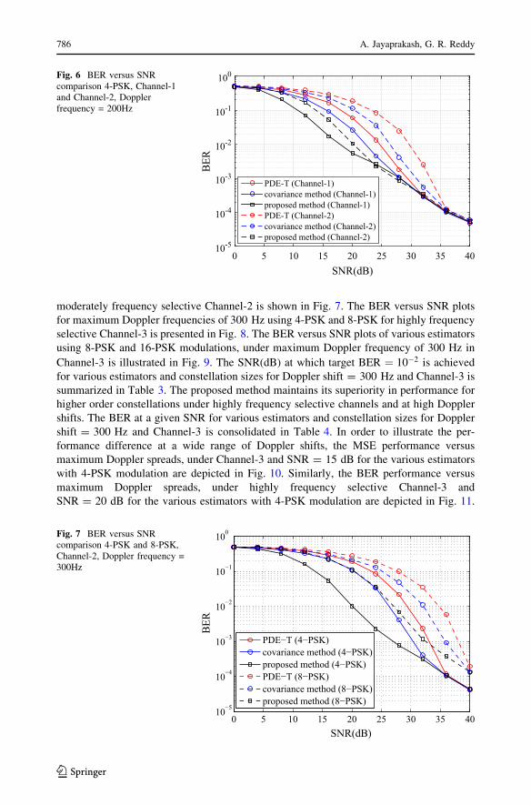
moderately frequency selective Channel-2 is shown in Fig. 7. The BER versus SNR plots
for maximum Doppler frequencies of 300 Hz using 4-PSK and 8-PSK for highly frequency
selective Channel-3 is presented in Fig. 8. The BER versus SNR plots of various estimators
using 8-PSK and 16-PSK modulations, under maximum Doppler frequency of 300 Hz in
Channel-3 is illustrated in Fig. 9. The SNR(dB) at which target BER ¼ 10�2 is achieved
for various estimators and constellation sizes for Doppler shift = 300 Hz and Channel-3 is
summarized in Table 3. The proposed method maintains its superiority in performance for
higher order constellations under highly frequency selective channels and at high Doppler
shifts. The BER at a given SNR for various estimators and constellation sizes for Doppler
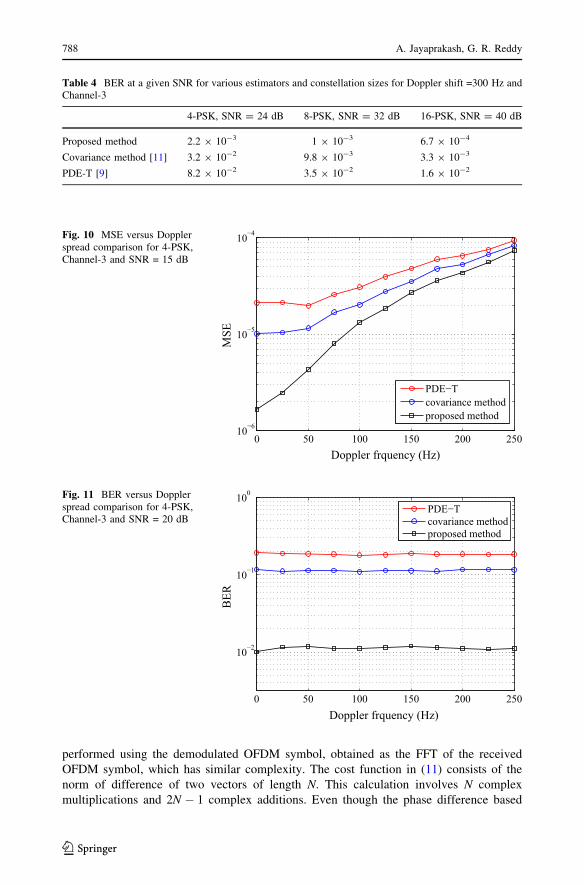
shift = 300 Hz and Channel-3 is consolidated in Table 4. In order to illustrate the per-
formance difference at a wide range of Doppler shifts, the MSE performance versus
maximum Doppler spreads, under Channel-3 and SNR = 15 dB for the various estimators
with 4-PSK modulation are depicted in Fig. 10. Similarly, the BER performance versus
maximum Doppler spreads, under highly frequency selective Channel-3 and
SNR = 20 dB for the various estimators with 4-PSK modulation are depicted in Fig. 11.
SNR(dB)0 5 10 15 20 25 30 35 40
BER
10-5
10-4
10-3
10-2
10-1
100
PDE-T (Channel-1)covariance method (Channel-1)proposed method (Channel-1)PDE-T (Channel-2)covariance method (Channel-2)proposed method (Channel-2)
Fig. 6 BER versus SNRcomparison 4-PSK, Channel-1and Channel-2, Dopplerfrequency = 200Hz
0 5 10 15 20 25 30 35 4010−5
10−4
10−3
10−2
10−1
100
BER
SNR(dB)
PDE−T (4−PSK)covariance method (4−PSK)proposed method (4−PSK)PDE−T (8−PSK)covariance method (8−PSK)proposed method (8−PSK)
Fig. 7 BER versus SNRcomparison 4-PSK and 8-PSK,Channel-2, Doppler frequency =300Hz
786 A. Jayaprakash, G. R. Reddy
123

The proposed estimator is showing significantly improved BER and MSE performance
than the other estimators in both low and high Doppler spread conditions.
The initial cost function in (11) is formulated with the first columns of the covariance
matrices of two OFDM symbols which can be generated using FFT operation, for which
the complexity is of the order of N. In the case of PDE-T method in [9], the estimation is
0 5 10 15 20 25 30 35 4010−5
10−4
10−3
10−2
10−1
100
BER
SNR(dB)
PDE−T (4−PSK)covariance method (4−PSK)proposed method (4−PSK)PDE−T (8−PSK)covariance method (8−PSK)proposed method (8−PSK)
Fig. 8 BER versus SNRcomparison 4-PSK and 8-PSK,Channel-3, Doppler frequency= 300Hz
0 5 10 15 20 25 30 35 4010−4
10−3
10−2
10−1
100
BER
SNR(dB)
PDE−T (8−PSK)covariance method (8−PSK)proposed method (8−PSK)PDE−T (16−PSK)covariance method (16−PSK)proposed method (16−PSK)
Fig. 9 BER versus SNRcomparison 8-PSK and 16-PSK,Channel-3, Doppler frequency= 300Hz
Table 3 SNR(dB) at which target BER ¼ 10�2 is achieved for various estimators and constellation sizesfor Doppler shift =300 Hz and Channel-3
4-PSK 8-PSK 16-PSK
Proposed method 20 27 34
Covariance method [11] 26 32 38
PDE-T [9] 30 35 [40
Robust Blind Carrier Frequency Offset... 787
123
performed using the demodulated OFDM symbol, obtained as the FFT of the received
OFDM symbol, which has similar complexity. The cost function in (11) consists of the
norm of difference of two vectors of length N. This calculation involves N complex
multiplications and 2N � 1 complex additions. Even though the phase difference based
Table 4 BER at a given SNR for various estimators and constellation sizes for Doppler shift =300 Hz andChannel-3
4-PSK, SNR = 24 dB 8-PSK, SNR = 32 dB 16-PSK, SNR = 40 dB
Proposed method 2.2 9 10-3 1 9 10-3 6.7 9 10-4
Covariance method [11] 3.2 9 10-2 9.8 9 10-3 3.3 9 10-3
PDE-T [9] 8.2 9 10-2 3.5 9 10-2 1.6 9 10-2
0 50 100 150 200 25010−6
10−5
10−4
Doppler frquency (Hz)
MSE
PDE−Tcovariance methodproposed method
Fig. 10 MSE versus Dopplerspread comparison for 4-PSK,Channel-3 and SNR = 15 dB
0 50 100 150 200 250
10−2
10−1
100
Doppler frquency (Hz)
BER
PDE−Tcovariance methodproposed method
Fig. 11 BER versus Dopplerspread comparison for 4-PSK,Channel-3 and SNR = 20 dB
788 A. Jayaprakash, G. R. Reddy
123

estimation step involves power computations, accurate estimates are achieved using very
less number of subcarriers which is N. The number complex multiplications involved in
the conventional PDE-T method [9] and the covariance method [11] are of the order of N.
Therefore, even though the total number of multiplications required by the proposed
method is slightly higher than that required by conventional methods, it is still of the order
of N as well as exhibits better performance under all channel conditions.
5 Conclusion
In this paper, we have put forward an unsupervised CFO estimation scheme for OFDM
system with constant modulus constellations based on joint covariance power fitting and
phase criterion. The proposed method is robust and shows a substantial performance
improvement than the conventional prominent CFO estimation schemes under time
varying channels with low and high delay spreads. The effectiveness of the proposed
method to adapt to time varying channels with high frequency selectivity is due to the
careful formulation of the objective function based on covariance power fitting and phase
criteria. The performance of the proposed method is compared with the conventional
methods in terms of MSE and BER under time varying channels with different frequency
selectivity and Doppler shifts. The proposed method shows excellent performance
improvement than the conventional methods under all the considered channel conditions,
even at low SNRs. The effectiveness of the proposed estimation schemes for higher order
constellations has also been evaluated through numerical simulations. The effect of various
Doppler shifts on the performance of the various estimators is also analyzed under time
varying channels and the proposed estimator attains improved MSE and BER performance
under low and high Doppler shifts.
Appendix
The derivation of the cost function given by (13) is presented in this Appendix. Let the first
column of the covariance matrix Rn eð Þ be rm lð Þ ¼ rmð0Þ; rmð1Þ; . . .; rmðN � 1Þ½ �T . Rm eð Þisobtained using the matrix Dm eð Þ. From (6) and (8), the l-th element of the rm lð Þ vector isobtained as
rm lð Þ ¼X
N�l�1
p¼0
dm pþ lð Þdm�ðpÞ þ
X
N�1
p¼N�l
dm pþ l� Nð Þdm�pð Þ: ð20Þ
The relationship between bdm and dm is obtained from (2), (3) and (6) as
bdm ¼ e�j2pem NþNpð Þ
N H�ee
j2pem NþNpð ÞN Hedm
If dm ¼ dmð0Þ; dmð1Þ; . . .; dmðN � 1Þ½ �T , the ath element of the vector bdm is given by
dm að Þ ¼ ej2p e�eð Þm NþNpð Þ
N ej2p e�eð Þa
N dm að Þ: ð21Þ
Using (21) in (20),
Robust Blind Carrier Frequency Offset... 789
123
rm lð Þ ¼ ej2p e�eð Þ lð Þ
N
X
N�l�1
p¼0
dm pþ lð Þd�m pð Þ þ ej2p e�eð Þ l�Nð Þ
N
X
N�1
p¼N�l
dn pþ l� Nð Þd�m pð Þ: ð22Þ
LetPN�l�1
p¼0 dm pþ lð Þd�m pð Þ be km;l andPN�1
p¼N�l dm pþ l� Nð Þd�m pð Þ be lm;l. Then
rm lð Þ ¼ ej2p e�eð Þl
N ðkm;l þ e�j2p e�eð Þlm;lÞ: ð23Þ
Similarly,
rmþ1 lð Þ ¼ ej2p e�eð Þl
N ðkmþ1;l þ e�j2p e�eð Þlmþ1;lÞ
and
rmþ1 lð Þ � rm lð Þð Þ ¼ ej2p e�eð Þl
N kmþ1;l � km;l�
þ e�j2p e�eð Þ lmþ1;l � lm;l�
� �
Let kmþ1;l � km;l�
=kl and lmþ1;l � lm;l�
=ll. Then rmþ1 lð Þ � rm lð Þk k2 can be minimized
to
rmþ1 lð Þ � rm lð Þk k2 ¼ klj j2 þ llj j2 þ 2Re kll�l
�
cos 2p e� eð Þ � 2Im k�l ll �
sin 2p e� eð Þ:ð24Þ
Since the channel characteristics remains invariant between two adjacent OFDM symbols,
in the absence of CFO and at high SNR, rmþ1 lð Þ ¼ rm lð Þ. Hence,
kmþ1;l þ lmþ1;l
�
¼ km;l þ lm;l�
. Therefore, kmþ1;l � km;l�
¼ � lmþ1;l � lm;l�
. i.e.
kl ¼ �ll. Hence the term Im k�l ll �
, associated with the sinusoidal term in (24) becomes
�Im klj j2n o
which is zero. Substituting kl ¼ �ll in (24), rmþ1 lð Þ � rm lð Þk k2 ¼ 2 klj j2�2 klj j2 cos 2p e� eð Þ. If, �2 klj j2 ¼ A, rmþ1 lð Þ � rm lð Þk k2 ¼ Acos 2p e� eð Þ � A. The con-
stant in the equation is independent of e� eð Þ and the cost function of (11) can be
approximated as J eð Þ ¼ A cos 2p e� eð Þð Þ � A.
References
1. van Nee, R., & Prasad, R. (2000). OFDM for wireless multimedia communications. Norwood, MA:Artech House, Inc.
2. ETSI Normalization Committee et al. (1995). Radio broadcasting systems, digital audio broadcasting(DAB) to mobile, portable and fixed receivers (Vol. 300, No. 401). Norme ETSI, Sophia-Antipolis,France, Doc. ETS, pp. 1995–1997.
3. Reimers, U. (1998). Digital video broadcasting. IEEE Communications Magazine, 36(6), 104–110.4. Li, Y. G., & Stuber, G. L. (2006). Orthogonal frequency division multiplexing for wireless communi-
cations. Berlin: Springer.5. Fazal, K., & Kaiser, S. (2008). Multi-carrier and spread spectrum systems: From OFDM and MC-
CDMA to LT. New York: Wiley.6. Yao, Y., & Giannakis, G. B. (2005). Blind carrier frequency offset estimation in SISO, MIMO, and
multiuser OFDM systems. IEEE Transactions on Communications, 53(1), 173–183.7. Al-Dweik, A. J. (2004). Robust non data-aided frequency offset estimation technique. In 15th IEEE
international symposium on personal, indoor and mobile radio communications, 2004. PIMRC 2004(Vol. 2), pp. 1365–1369
8. Zeng, X. N., & Ghrayeb, A. (2008). A blind carrier frequency offset estimation scheme for OFDMsystems with constant modulus signaling. IEEE Transactions on Communications, 56(7), 1032–1037.
790 A. Jayaprakash, G. R. Reddy
123
9. Al-Dweik, A., Hazmi, A., Younis, S., Sharif, B., & Tsimenidis, C. (2010). Carrier frequency offsetestimation for OFDM systems over mobile radio channels. IEEE Transactions on Vehicular Technol-ogy, 59(2), 974–979.
10. Lmai, S., Bourre, A., Laot, C., & Houcke, S. (2014). An efficient blind estimation of carrier frequencyoffset in OFDM systems. IEEE Transactions on Vehicular Technology, 63(4), 1945–1950.
11. Oh, J.-H., Kim, J.-G., & Lim, J.-T. (2011). Blind carrier frequency offset estimation for OFDM systemswith constant modulus constellations. IEEE Communications Letters, 15(9), 971–973.
12. Al-Dweik, A., Hazmi, A., Younis, S., Sharif, B., & Tsimenidis, C. (2010). Blind iterative frequencyoffset estimator for orthogonal frequency division multiplexing systems. IET Communications, 4(16),2008–2019.
13. Roman, T., Visuri, S., & Koivunen, V. (2006). Blind frequency synchronization in OFDM via diago-nality criterion. IEEE Transactions on Signal Processing, 54(8), 3125–3135.
Arunprakash Jayaprakash received his B.Tech degree in Electronicsand Communication Engineering from University of Kerala, Trivan-drum, India, in 2008 and his M.Tech degree from VIT University,Vellore, India in 2013. He worked as a Lecturer in Electronics andCommunication Engineering Department of University College ofEngineering, Kariavattom, Trivandrum from September 2009 to May2011. Currently he is working as adhoc faculty in Electronics andCommunication department at NIT Calicut. He is working towards hisPh.D. degree in Signal Processing and Communication Engineering atVIT University, Vellore, India. His research areas of interest includeDigital Signal Processing, Digital Image Processing and signal pro-cessing for Wireless Multicarrier Communication systems.
G. Ramachandra Reddy (SM IEEE’90) received the M.Sc. andM.Sc.(Tech.) degrees from the Birla Institute of Technology andScience, Pilani, India, in 1973 and 1975, respectively, and the Ph.D.degree from the Indian Institute of Technology, Madras, India, in 1987.In 1976, he joined the Department of Electrical and ElectronicsEngineering, College of Engineering, Sri Venkateswara University,Tirupati, India, as a Lecturer, and superannuated as professor in theyear 2010. He is currently working as senior professor in the School ofElectronics Engineering, VIT University, Vellore, India. FromFebruary 1989 to May 1991, he was with the Department of Electricaland Computer Engineering, Concordia University, Montreal, QC,Canada, as a Visiting Scientist. Dr. Ramachandra Reddy is a Fellow ofthe Institution of Electronics and Telecommunication Engineers and amember of the Indian Society for Technical Education.
Robust Blind Carrier Frequency Offset... 791
123


