1 data-carrier aided frequency offset estimation for ofdm systems
Post on 19-Dec-2015
217 views
TRANSCRIPT

1
Data-carrier Aided Frequency Offset Estimation for OFDM Systems

2
Outline
Motivations Background knowledge Conventional CFO estimation strategies Modified CFO estimation strategies Simulation results Conclusions

3
Outline
Motivations Background knowledge Conventional CFO estimation strategies Modified CFO estimation strategies Simulation results Conclusions

4
Motivations
Motivations The conventional carrier frequency offset estimation
methods: pilot, cyclic prefix, training symbol Our proposed schemes: adopting the received signal on
data-carriers Providing more accurate frequency synchronization, or
reducing the pilot numbers to raise transmitted data rate.
5
Outline
Motivations Background knowledge Conventional CFO estimation strategies Modified CFO estimation strategies Simulation results Conclusions
6
Carrier Frequency Offset
What result in carrier frequency offset (CFO)? Mismatch between the oscillators at the TX and RX Doppler frequency
Carrier frequency offset can be divided into: Integral part Fractional part

7
OFDM System Model
C is pilot sequence h is time domain channel impulse response w is additive white Gaussian noise. N data information {S(n)} which have been modulated with N modulation
values {X(n)} on every sub-carrier
x ( t )
Channel h ( t)
S ( n )
r (t )ˆ ( )S n
S/P
P/S
X ( n ) x ( k )
Adding Pilots C(n) &IFFT
AddingCyclicPrefix & P/S
DACSignal
Mapper
z (t )
( )R n
FFT RemoveCyclicPrefix & S/P
ADC
SignalDemapper
( )r n
AWGN w ( t)
The OFDM system model:

8
OFDM System Model
The k sample of an OFDM block generated by IFFT :
N: number of subcarriersNg: length of cyclic prefix
12 /
0
1( ) ( ) ,0 1
Nj kn N
k
x k X n e k NN
[ ( ),..., ( 1), (0),..., ( 1)]gx x N N x N x x N
z x h
( ) ( ) ( )r k z k w k
12 /
0
( ) ( ) ,0 1N
j kn N
k
R n r k e n N

9
UWB Channel Model
Four environments in this UWB channel model: CM1 model is based on LOS (0-4m) channel measurements in [2] CM2 model is based on NLOS (0-4m) channel measurements in [2] CM3 model is based on NLOS (4-10m) channel measurements in [2],
and NLOS in [3] CM4 the model generated to fit a 25nsec RMS delay spread.
Time
Signal strength
: cluster decay factor : path decay factor : cluster arrival rate : the arrival rate of path within each cluster

10
Outline
Motivations Background knowledge Conventional CFO estimation strategies Modified CFO estimation strategies Simulation results Conclusions
11
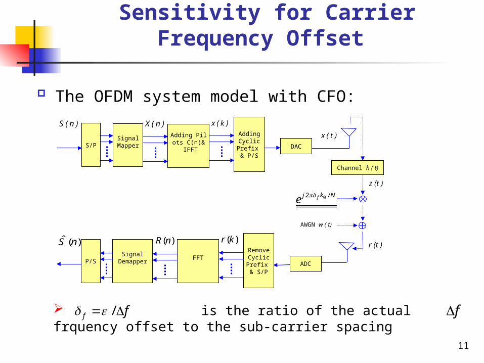
Sensitivity for Carrier Frequency Offset
The OFDM system model with CFO:
x ( t )
Channel h ( t)
S ( n )
S/P
X ( n ) x ( k )
Adding Pilots C(n)& IFFT
AddingCyclicPrefix & P/S
DACSignal
Mapper
z (t )
r (t )ˆ ( )S n
P/S
( )R n
FFTRemoveCyclicPrefix & S/P
ADC
SignalDemapper
( )r k
AWGN w ( t)
02 /fj k Ne
is the ratio of the actual frquency offset to the sub-carrier spacing/f f f

12
Sensitivity for Carrier Frequency Offset
The k-th received sample of the m-th symbol is given by
FFT 12 /
0
1 12 ( ) / 2 /2 / 2 /
0 0
12 ( ) / 2 ( ) /
0 0
( ) ( ) ,0 1
1 ( )
( )
1 ( )
g g f f
g g f f
Nj kn N
m mk
N Nj mN mN N N j k Nj kn N j ik N
m ii k
m
N Nj mN mN N N j k i n N
m ii k
R n r k e n N
e X i H e e eN
W n
e X i H eN
1
( )mW n
( ) ( ) ( ) ( )m mm mR n S n I n W n
2 ( ) /( ) ( ) (k),0 1f g gj mN mN N k Nm m mr k z k e w k N

13
Pilot tone - aided CFO Estimation
PTA CFO estimation:
( ) / ( )
2 arg ,( ) / ( )
i
g m D i m D if PTA i
n P m i m i
N N R n C nD n P
N R n C n
( ) / ( )1 1arg
2 ( ) / ( )i
m D i m D if PTA
n Pg m i m i
R n C nN
N N D R n C n
R1 R2
Pilot1 (n1)
Pilot2 (n2)
Pilot3 (n3)
f
t
Rm Rm+D
Let P denote the set of indexes of the Np pilot carriers
I
Q

14
Pilot tone - aided CFO Estimation
PTA with weighting (PTAW) CFO estimation:
* *2 arg ( ) ( ) ( ) ( ) ,gf PTAW m m D m m D i
n P
N ND R n R n C n C n n P
N
* *1 1arg ( ) ( ) ( ) ( )
2f PTAW m m D m m Dn Pg
NR n R n C n C n
N N D
f
Let P denote the set of indexes of the Np pilot carriers
I
QR1 R2
Pilot1 (n1)
Pilot2 (n2)
Pilot3 (n3)
t
Rm Rm+D

15
CP (Ng)
Symbol 1 Symbol 2(N+Ng)
(CL-1)
(L)
Cyclic Prefix - based CFO Estimation
CL is the channel length
*
0
2 arg ( ) ( )gN CL
f CPB m ml
r k l r k l N
*
0
1arg ( ) ( )
2
gN CL
f CPB m ml
r k l r k l N
*
0
2 arg ( ) ( )gN L
f CPB m ml
r k l r k l N
*
0
1arg ( ) ( )
2
gN L
f CPB m ml
r k l r k l N

16
Outline
Motivations Background knowledge Conventional CFO estimation strategies Modified CFO estimation strategies Simulation results Conclusions
17
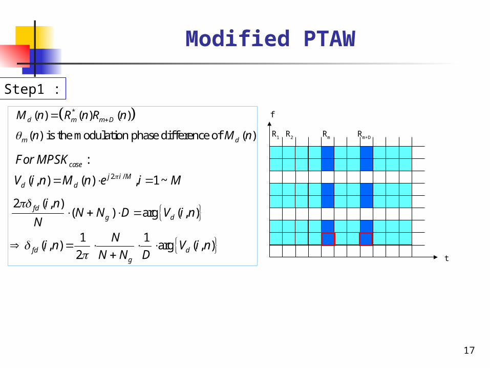
Modified PTAW
R1 R2
t
Rm Rm+D
f
Step1 :
*( ) ( ) ( )
( ) is the modulation phase difference of ( )
d m m D
m d
M n R n R n
n M n
2 /
:
( , ) ( ) , 1 ~
case
j i Md d
For MPSK
V i n M n e i M
2 ( , )
( ) arg ( , )fdg d
i nN N D V i n
N
1 1( , ) arg ( , )
2fd dg
Ni n V i n
N N D

18
Modified PTAW
Step2 :
2 arg ( )gf PTAW p
n p
N ND V n
N
* *( ) ( ) ( ) ( ) ( ) ,p m m D m m DV n R n R n C n C n n p
1 1arg ( )
2f PTAW pn pg
NV n
N N D
f
R1 R2
Pilot1 (n1)
Pilot2 (n2)
Pilot3 (n3)
t
Rm Rm+D

19
Modified PTAW
Find ( ), which is the closest ( , ) to for each fd fd f PTAWn i n n
( , )fd i n
Step4 :
Step3 :
2 ˆ( ) arg ,f MPTAWg p dN N D V V
N
1 1 ˆarg ,2f MPTAW p d
g
NV V
N N D
Each data-subcarrier d(n) has M candicates ,i=1…M
ˆ is the set of all ( ) ( )d d fdV V n corresponding to each n

20
Modified CPB
Step2 :
*
0
2 arg ( ) ( )gN CL
f CPB m ml
r k l r k l N
*
0
1arg ( ) ( )
2
gN CL
f CPB m ml
r k l r k l N
Step1 :
*( ) ( ) ( )
( ) is the modulation phase difference of ( )
d m m D
m d
M n R n R n
n M n
2 /
:
( , ) ( ) , 1 ~
case
j i Md d
For MPSK
V i n M n e i M
2 ( , )
( ) arg ( , )fdg d
i nN N D V i n
N
1 1( , ) arg ( , )
2fd dg
Ni n V i n
N N D

21
Modified CPB
Step4 :
Step3 :
2 ˆ( ) argf MCPBg dN N D V
N
1 1 ˆarg2f MCPB d
g
NV
N N D
Each data-subcarrier d(n) has M candicates ,i=1…M
Find ( ), which is the closest ( , ) to for each fd fd f PTAWi i n n
ˆ is the set of all ( ) ( )d d fdV V i corresponding to each i
( , )fd i n

22
Outline
Motivations Background knowledge Conventional CFO estimation strategies Modified CFO estimation strategies Simulation results Conclusions

23
Optimum L for CPB Method
CM1
0 5 10 15 20 25 30 3510
-6
10-5
10-4
10-3
10-2
L
MS
E
N=128 Np=12 DF=0.1 SNR=50
CPB for BPSKCPB for QPSKCPB for 8PSKMCPB for BPSKMCPB for QPSKMCPB for 8PSK

24
Optimum L for CPB Method
CM3
0 5 10 15 20 25 30 3510
-3
10-2
10-1
L
MS
E
N=128 Np=12 DF=0.1 SNR=50
CPB for BPSKCPB for QPSKCPB for 8PSKMCPB for BPSKMCPB for QPSKMCPB for 8PSK

25
Discussion of Pilot Numbers
CM1
0 20 40 60 80 100 120 14010
-6
10-5
10-4
10-3
Np
MS
E
N=128 DF=0.1 SNR=50
PTAW for BPSKPTAW for QPSKPTAW for 8PSKMPTAW for BPSKMPTAW for QPSKMPTAW for 8PSK

26
Discussion of Pilot Numbers
CM3
0 20 40 60 80 100 120 14010
-5
10-4
10-3
Np
MS
E
N=128 DF=0.1 SNR=50
PTAW for BPSKPTAW for QPSKPTAW for 8PSKMPTAW for BPSKMPTAW for QPSKMPTAW for 8PSK

27
Performance Comparison
CM1 BPSK
0 5 10 15 20 25 30 35 40 45 5010
-6
10-5
10-4
10-3
10-2
10-1
SNR(dB)
MS
E
BPSK N=128 Np=12 DF=0.1
CPBMCPBPTAPTAWMPTAW

28
Performance Comparison
CM1 QPSK
0 5 10 15 20 25 30 35 40 45 5010
-5
10-4
10-3
10-2
10-1
SNR(dB)
MS
E
QPSK N=128 Np=12 DF=0.1
CPBMCPBPTAPTAWMPTAW

29
Performance Comparison
CM1 8PSK
0 5 10 15 20 25 30 35 40 45 5010
-5
10-4
10-3
10-2
10-1
SNR(dB)
MS
E
8PSK N=128 Np=12 DF=0.1
CPBMCPBPTAPTAWMPTAW
30
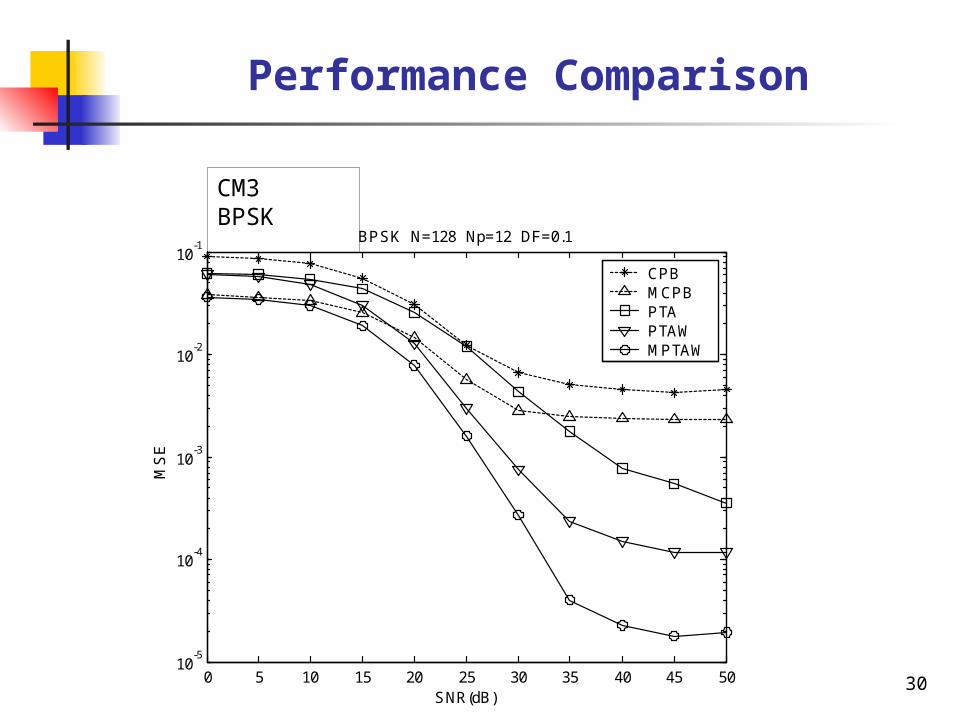
Performance Comparison
CM3 BPSK
0 5 10 15 20 25 30 35 40 45 5010
-5
10-4
10-3
10-2
10-1
SNR(dB)
MS
E
BPSK N=128 Np=12 DF=0.1
CPBMCPBPTAPTAWMPTAW

31
Performance Comparison
CM3 QPSK
0 5 10 15 20 25 30 35 40 45 5010
-5
10-4
10-3
10-2
10-1
SNR(dB)
MS
E
QPSK N=128 Np=12 DF=0.1
CPBMCPBPTAPTAWMPTAW
32
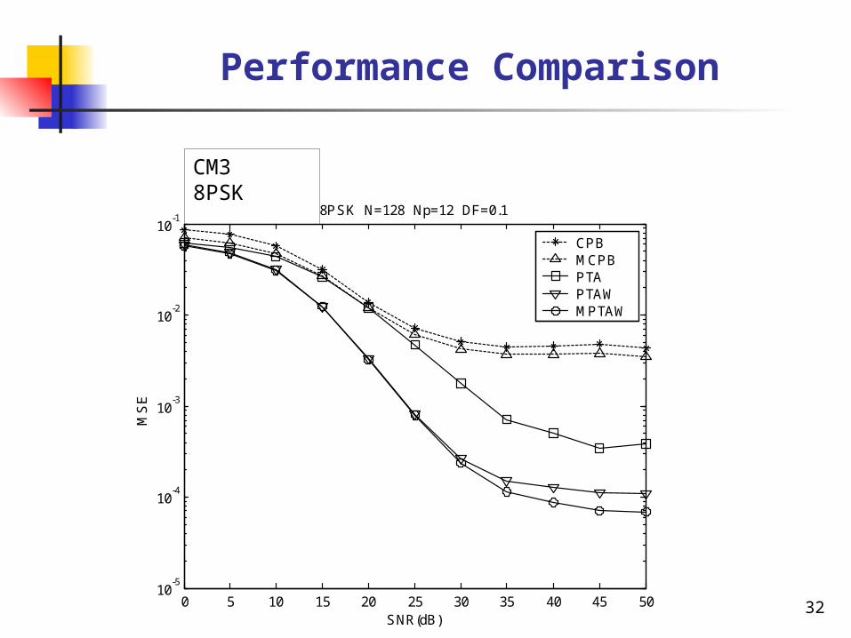
Performance Comparison
CM3 8PSK
0 5 10 15 20 25 30 35 40 45 5010
-5
10-4
10-3
10-2
10-1
SNR(dB)
MS
E
8PSK N=128 Np=12 DF=0.1
CPBMCPBPTAPTAWMPTAW

33
Outline
Motivations Background knowledge Conventional CFO estimation strategies Modified CFO estimation strategies Simulation results Conclusions

34
Conclusions
Advantages: The key advantages of our proposed algorithms is to provide mor
e accurate frequency synchronization and reduce pilot numbers to raise bandwidth efficiency.
Comparison with conventional methods: The MCPB performs better than CPB (lower MSE). The MPTAW performs better than two traditional pilot tone-aide
d methods, and we can achieve the same performance as PTAW by less pilot numbers.
The best choices: If there is acceptable ISI, the MCPB will be the most suitable me
thod to estimate CFO because it can provide excellent MSE with its superior resistance of ICI and constellation size.
If there is serious ISI, the MPTAW is the best choice under this condition since it is robust to time domain interference.

35
Thank you ~

36
Reference
[1] J. R. Foerster, Ed., “Channel Modeling Sub-committee Report Final,” IEEE P802.15 SG3a contribution.
[2] H. Chen and G.J. Pottie, "A Comparison of Frequency Offset Tracking Algorithms for OFDM", GLOBECOM '03, vol.2, pp. 1069-1073, Dec. 2003.
[3] K. Shi, E. Serpedin, and P. Ciblat, “Decision-directed fine synchronization for coded OFDM systems,” in Proc. IEEE International Conf. on Acoustics, Speech, and Signal Processing. (ICASSP’04), vol. 4, pp. 365-368, 17-21 May 2004.