
Performance of Ground Source Heat Pumps in Manitoba
Prepared By: Rob Andrushuk, C.Tech Phil Merkel, C.Tech Manitoba Hydro Customer Engineering Services Reviewed By: Denton Vandersteen, P.Eng. Manitoba Hydro Customer Engineering Services June, 2009 Project Co-Funded By:
* Manitoba Hydro is a licensee of the Trademark and Official Mark
MANITOBA HYDRO MONITORING STUDY

© 2009 MANITOBA HYDRO. All Rights Reserved
Page ii
This Manitoba Hydro report, and all information, drawings, procedures, methods, presentation, etc. contained (collectively referred to as the “Report”) is provided subject to the following terms and conditions. If any recipient does not agree to, or is uncertain as to, any term or condition governing the use of the Report, please do not access or use this Report, and immediately contact Manitoba Hydro’s Earth Power Program at (204) 360-4273 to arrange for its return to Manitoba Hydro: THE REPORT IS PROVIDED “AS IS” AND WITHOUT WARRANTY OF ANY KIND AND MANITOBA HYDRO EXPRESSLY DISCLAIMS ALL WARRANTIES, CONDITIONS, UNDERTAKINGS, OR TERMS, WHETHER EXPRESS OR IMPLIED, WRITTEN OR ORAL, STATUTORY OR OTHERWISE, INCLUDING, WITHOUT LIMITATION, ANY EXPRESS OR IMPLIED WARRANTIES AS TO MERCHANTABILITY, MERCHANTABLE QUALITY, AND FITNESS FOR ANY PARTICULAR PURPOSE. MANITOBA HYDRO DOES NOT WARRANT, GUARANTEE, OR MAKE ANY REPRESENTATION WHATSOEVER REGARDING THE USE, RESULTS OF USE, ACCURACY, CORRECTNESS, USEFULNESS, RELIABILITY, NON-INFRINGEMENT OF ANY THIRD PARTY RIGHT, OR FITNESS FOR ANY PARTICULAR PURPOSE, OF THE REPORT. THE ENTIRE RISK AS TO THE USE OR INABILITY TO USE OF THE REPORT IS ASSUMED SOLELY BY THE RECIPIENT. REGARDLESS OF CIRCUMSTANCES AND REGARDLESS OF THE FORM OF ACTION, WHETHER IN CONTRACT OR IN TORT (INCLUDING NEGLIGENCE OR PRODUCTS LIABILITY) OR UNDER ANY OTHER LEGAL THEORY, MANITOBA HYDRO SHALL NOT BE LIABLE FOR ANY DIRECT, INDIRECT, INCIDENTAL, CONSEQUENTIAL, SPECIAL, PUNITIVE OR EXEMPLARY LOSSES OR DAMAGES OF ANY NATURE OR KIND WHATSOEVER, INCLUDING, BUT NOT LIMITED TO, LOSSES OR DAMAGES ARISING OUT OF OR RESULTING IN ANY MANNER FROM ANY USE OF OR ANY INABILITY TO USE THE REPORT, EVEN IF MANITOBA HYDRO MAY HAVE BEEN ADVISED OF THE POSSIBILITY OF SUCH LOSSES OR DAMAGES OR IF SUCH LOSSES OR DAMAGES WERE REASONABLY FORSEEABLE.

© 2009 MANITOBA HYDRO. All Rights Reserved
Page iii
Acknowledgements
This monitoring project was co-funded by Manitoba Hydro and the Canadian GeoExchange Coalition (CGC). Manitoba Hydro wishes to thank the CGC for their contribution to this project.
Manitoba Hydro wishes to further acknowledge and thank the heat pump contractors and the homeowners who were involved in this project for their co-operation. Without their assistance this project would not have been possible.

© 2009 MANITOBA HYDRO. All Rights Reserved
Page iv
TABLE OF CONTENTS
1.0 Executive Summary........................................................................................................................vii 2.0 Background...................................................................................................................................... 1 3.0 Study Objectives .............................................................................................................................. 2 4.0 Test Method ..................................................................................................................................... 3 4.1 SCOP............................................................................................................................................... 3 4.2 SEER ............................................................................................................................................... 3 4.3 Desuperheater Energy Savings....................................................................................................... 4 5.0 Heat Pump System Monitoring Method ........................................................................................... 5 5.1 Total Electrical Energy (kWh) Input into the System ....................................................................... 5 5.2 Total Energy (BTUh) to and from Ground Loop Heat Exchanger .................................................. 5 5.2.1 Ground Loop Temperature Measurements .................................................................................... 6 5.2.2 Ground Loop Fluid Flow Measurements......................................................................................... 6 5.2.3 Ground Loop Fluid Specific Gravity Verification .............................................................................. 7 5.2.4 Ground Loop Fluid Flow Meter Correction Factor .......................................................................... 7 6.0 Desuperheater Monitoring Method .................................................................................................. 8 7.0 Verification of Measurements and Accuracies ................................................................................ 9 7.1 Monitoring Equipement Accuracy and Precision Verification .......................................................... 9 7.1.1 Current Transducers ....................................................................................................................... 9 7.1.2 Potential Transducers ..................................................................................................................... 9 7.1.3 RTD Temperature Sensors........................................................................................................... 10 7.1.4 Enernet K20 Data Logger ............................................................................................................. 10 7.1.5 Ground Loop Flow Meters and Domestic Hot Water Volumetric Meters...................................... 10 7.2 Installation and Post-Installation Verification (in-situ) Testing ....................................................... 10 8.0 Test Site Selection ......................................................................................................................... 11 9.0 Heating System Performance........................................................................................................ 12 9.1 Energy Efficiency ........................................................................................................................... 12 9.2 Cost Savings.................................................................................................................................. 15 9.3 Auxiliary Heat................................................................................................................................. 15 9.4 Entering Fluid Temperatures ......................................................................................................... 16 9.5 Compressor ................................................................................................................................... 17 9.6 Ground Loop Pump........................................................................................................................ 18 9.7 Fan Motor....................................................................................................................................... 19 10.0 Cooling Season Performance........................................................................................................ 20 11.0 Domestic hot Water Heater Savings.............................................................................................. 22 12.0 Operating Statistics........................................................................................................................ 24 12.1 Heat Pump Run Hours (Heating Mode)......................................................................................... 24 12.2 Heat Pump Run Hours (Cooling Mode) ......................................................................................... 25 12.3 Heat Pump Starts........................................................................................................................... 25

© 2009 MANITOBA HYDRO. All Rights Reserved
Page v
13.0 Conclusions ................................................................................................................................... 27 14.0 Recommendations ......................................................................................................................... 28 Appendix A - General House Descriptions ................................................................................................. 29 Appendix B - Map of Monitored Locations.................................................................................................. 40 Appendix C - Data Acquasition Devices ..................................................................................................... 42 Appendix D - Test Instruments and Reference Standards ......................................................................... 46 Appendix E - SCOP and SEER Calculation Constants .............................................................................. 48 Appendix F - Monthly Heat Pump Energy Data Tables.............................................................................. 50 Appendix G - Domestic Hot Water Data Tables ......................................................................................... 61 Appendix H - Run Hour and Starts Data Tables......................................................................................... 68 Appendix I - Entering Fluid Temperature Data Tables ............................................................................... 72

© 2009 MANITOBA HYDRO. All Rights Reserved
Page vi
LIST OF TABLES Table 1 - Monthly Heat Pump Data for House # 1...................................................................................... 51 Table 2 - Monthly Heat Pump Data for House # 2...................................................................................... 52 Table 3 - Monthly Heat Pump Data for House # 3...................................................................................... 53 Table 4 - Monthly Heat Pump Data for House # 4...................................................................................... 54 Table 5 - Monthly Heat Pump Data for House # 5...................................................................................... 55 Table 6 - Monthly Heat Pump Data for House # 6...................................................................................... 56 Table 7 - Monthly Heat Pump Data for House # 7...................................................................................... 57 Table 8 - Monthly Heat Pump Data for House # 8...................................................................................... 58 Table 9 - Monthly Heat Pump Data for House # 9...................................................................................... 59 Table 10 - Monthly Heat Pump Data for House # 10.................................................................................. 60 Table 11 - Annual Domestic Hot Water Data Summary for Monitored Houses ......................................... 62 Table 12 - Monthly Domestic Hot Water Data for House # 1 ..................................................................... 63 Table 13 - Monthly Domestic Hot Water Data for House # 2 ..................................................................... 63 Table 14 - Monthly Domestic Hot Water Data for House # 3 ..................................................................... 64 Table 15 - Monthly Domestic Hot Water Data for House # 4 ..................................................................... 64 Table 16 - Monthly Domestic Hot Water Data for House # 5 ..................................................................... 65 Table 17 - Monthly Domestic Hot Water Data for House # 6 ..................................................................... 65 Table 18 - Monthly Domestic Hot Water Data for House # 7 ..................................................................... 66 Table 19 - Monthly Domestic Hot Water Data for House # 8 ..................................................................... 66 Table 20 - Monthly Domestic Hot Water Data for House # 9 ..................................................................... 67 Table 21 - Monthly Domestic Hot Water Data for House # 10 ................................................................... 67 Table 22 - Heat Pump Annual Run Hour Data (Total)................................................................................ 69 Table 23 - Heat Pump Run Hour Data (Heating Mode).............................................................................. 70 Table 24 - Heat Pump Run Hour Data (Cooling Mode).............................................................................. 70 Table 25 - Annual Heat Pump Compressor Starts Data............................................................................. 71 Table 26 - Average Entering Fluid Temperature Data (Heating Mode)...................................................... 73 Table 27 - Average Entering Fluid Temperature Data (Cooling Mode)...................................................... 73 Table 28 - Minimum/Maximum Entering Fluid Temperature Data.............................................................. 74

© 2009 MANITOBA HYDRO. All Rights Reserved
Page vii
1.0 Executive Summary:
Manufacturers of geothermal heat pumps have traditionally reported coefficients of performance (COP) of 3.1-to-4.0 and energy efficiency ratio (EER) of 14-to-24. These efficiency levels are based on instantaneous tests conducted under controlled conditions and do not consider all of the losses that may occur in an installed system operating in varying conditions.
This study monitored ten homes over an extended period during all heating, cooling and shoulder months to determine the average Seasonal Coefficient of Performance (SCOP) and Seasonal Energy Efficiency Ratio (SEER) of typical heat pump systems operating in an “as-installed” environment.
Test data for ten Manitoba homes shows that the SCOP of the monitored ground source heat pump systems range from 1.8 to 3.5 with an average of 2.8 for a one year period. SCOP is defined as the total energy (kWh) delivered by the system divided by the total electric energy input (kWh) to the system over one heating season. The average annual electric energy saved was 15,842 kWh when compared to conventional electric resistance heat. The systems operated for an average of 2041 equivalent full load hours in heating mode.
The average SEER of the ten monitored homes during the cooling season was 13.3. The estimated average annual energy saved was 17 kWh compared to a split central air conditioning system with a SEER of 13. The cooling savings with a ground source heat pump were minimal but this may not be a fair comparison since the SEER 13 assumed for the central air conditioner is based on controlled test conditions and is not based on actual monitored field data. The systems operated for an average of 218 equivalent full load hours in the cooling mode.
The desuperheater option reduced the average domestic hot water electric energy usage by 610 kWh (18%). It was found that 86% of the savings were produced during the heating season. Therefore, the heat pump had to operate longer to transfer this additional energy requirement. This additional energy requirement during the heating season only increased seasonal imbalance on the ground. Most of the systems operated with storage water tank temperatures lower than the 60 oCelsius (140 o Fahrenheit) that is the minimum temperature setting requirement of the National Plumbing Code for electric storage water heaters. One of the desuperheater pumps was replaced prior to the study period due to motor failure. Another pump failed during the study period. Considering all of these factors, the desuperheater option does not appear to provide the same benefit in a heating dominated climate as it would in a cooling dominated climate.

Page 1
2.0 Background:
Manitoba Hydro has been promoting geothermal heat pump systems through the Residential Earth Power Program since April of 2002. Since program launch, over 950 customers have applied for the Residential Earth Power Loan. Manitoba Hydro has worked with industry and other partners to determine the actual geothermal system performance over an entire heating and cooling season. The performance levels reported by various manufacturers are based on an instantaneous test and do not consider all of the losses that occur in an actual system. The performance values reported in this study reflect measured performance values monitored at “as-installed” working systems.
In two previous case studies in Manitoba, where actual field performance was measured it was found that the seasonal coefficient of performance (SCOP) over an entire heating season for five homes ranged from 1.4 to 2.9. The case study that included four homes indicated that two of the homes produced SCOP’s of 1.4 and 1.6 but lack of maintenance and improper use of the system was found to be the cause of their poor performance. The other two homes in that study had no operational issues and produced SCOP’s of 2.5 and 2.8. The second previous case study was of a single home, measured a SCOP of 2.9 for one heating season, and an SCOP of only 2.2 in a subsequent heating season. The reduction in performance in the second year was caused by a control failure which caused the auxiliary heat to operate excessively.
Based on the two previous case studies and analysis of heat pump customer billing data, Manitoba Hydro uses an average ground source heat pump SCOP of 2.5 and an EER of 14 for calculating the energy savings claimed by our Earth Power program. Manitoba Hydro wanted to study more residential ground source heat pump installations to provide a larger and more varied sample. A larger sample was expected to more accurately represent heat pump SCOP’s of reasonably installed systems and therefore ensure that the energy savings claimed by the program would be fair and realistic.
It was felt that more extensive research needed to be completed to clarify the circumstances under which a desuperheater is beneficial in a heating dominated climate such as Manitoba. This is important because the high cost of a desuperheater increases the initial cost of the system and the high cost barrier of geothermal systems has been identified as one of three main barriers to widespread adoption of the technology. Removing the desuperheater from this initial cost may reduce the simple payback period. Conversely, when circumstances make the desuperheater a worthwhile investment, the payback period on the overall system may actually be reduced. Actual desuperheater field performance needed to be measured.

© 2009 MANITOBA HYDRO. All Rights Reserved
Page 2
Since Manitoba is a heating dominated climate there are concerns regarding the long term thermal performance of the ground loop. This study will measure the annual energy imbalance that is placed on the ground loop due to heating, cooling, and hot water (desuperheater). The annual energy imbalance is calculated by subtracting the quantity of heat rejected to the ground from the quantity of heat removed from the ground loop in a one year period.
3.0 Study Objectives:
The objectives of the study were to determine:
1. an average annual Seasonal Coefficient of Performance (SCOP for the heating season), and an average Seasonal Energy Efficiency Ratio (SEER for the cooling season),
2. the average annual water heating electric energy reduction due to the desuperheater, and
3. the average annual heating savings provided by a reasonably well installed ground source heat pump system in Manitoba.
The ten homes monitored are a biased sample since most of the homes were volunteered for the project by experienced and established heat pump contractors and /or distributors that were contacted and nine of the systems were relatively new (less than three years old). The one older system in the study was the only open loop (well to well system) in the study. This system was re-commissioned when it was discovered at the preliminary site visit that it was performing poorly (COP of 1.5) due to water supply issues.

© 2009 MANITOBA HYDRO. All Rights Reserved
Page 3
4.0 Test Method:
Monitoring of these systems was achieved by sub-metering the ground loop energy (extraction and rejection), the electrical energy provided to all the electrical components connected to the heat pump unit, the energy provided by the desuperheater (DSH), and the electrical energy provided to the domestic hot water heater for ten homes located throughout Manitoba for an entire heating and cooling season.
4.1 Seasonal Coefficient of Performance (SCOP*)
The SCOP* of each unit was determined by summing the heat energy provided to the home by the ground loop with the heat energy provided to the home by the electrical components of the heat pump then dividing the sum by the electrical energy required to operate the heat pump for an entire heating season.
SCOP Calculation:
SCOP = kWhGL + kWhEL1 kWhEL2
Where: kWhGL = Ground Loop kWh Output kWhEL1 = compressor, fan, DSH pump, aux. heater kWh usage
kWhEL2 = compressor, fan, DSH pump, aux. heater and ground loop pump kWh usage
4.2 Seasonal Energy Efficiency Ratio (SEER*)
The SEER* of each unit was determined by adding the heat energy (BTU) rejected to the ground loop and the desuperheater during the cooling season, subtracting the heat energy (BTU) provided to the ground loop and desuperheater loop by the electrical components then dividing this total by the electrical energy required to operate the heat pump for an entire cooling season.
SEER Calculation:
SEER = (BTUGL + BTUDSH) - (BTUEL) WhEL
Where: BTUGL = heat rejected to ground loop BTUDSH = heat rejected to desuperheater
BTUEL = Compressor, Fan, and desuperheater pump electrical usage (kWh) converted to BTU
*The ground loop pump electrical energy consumption was not included in the electrical heat energy since it was already accounted for in the ground loop heat energy measurements.

© 2009 MANITOBA HYDRO. All Rights Reserved
Page 4
4.3 Desuperheater (DSH) Energy Savings
DSH Energy Savings (kWh) = kWhDSH - kWhELDSH(heating Mode or Cooling Mode)
Where: kWhDSH = DSH Output (kWh)
kWhELDSH = electrical energy into desuperheater energy output kWhELDSH (Heating Mode) =DSH Output(kWh)/COP
kWhELDSH (Cooling Mode) = DSH pump energy(kWh)

© 2009 MANITOBA HYDRO. All Rights Reserved
Page 5
5.0 Heat Pump System Monitoring Method:
To determine the SCOP and SEER of each heat pump system, the following values were required to be measured and applied to the SCOP and SEER Calculations:
1. Total kWh electrical energy input into the system 2. Total BTU Output from the ground loop heat exchanger.
Refer to Appendix C for a listing of measurement and monitoring devices and specifications.
5.1 Total Electrical Energy (kWh) Input into the System:
The following electrical loads were monitored to determine total kWh energy consumed by the heat pump system:
1. Compressor (Stage 1 and 2 if applicable) 2. Auxiliary Heat 3. Ground Loop Pump (1 or 2 pumps, Stage 1 and 2 as applicable) 4. Fan Motor (heating and cooling mode) 5. Desuperheater pump
Split-core current transducers (CT’s) were placed on the conductor supplying each electrical component so that each component’s consumption could be measured and monitored separately. One potential transducer (PT) was connected to the main electrical service panel to reference the line-to-line voltage supply to the heat pump system. This allowed the data logger to monitor correct Power Factor and kWh measurements of each component.
The CT’s and PT’s selected for this project have a manufacturer stated accuracy value of ± 1.0% of measured value.
Refer to Appendix C for detailed CT and PT specifications. 5.2 Total Energy (BTU) to and from the ground loop heat exchanger:
Q = m⋅cp⋅ΔT
Where: Q = heat energy transferred [BTU] m = mass [pounds] cp = heat capacity [BTU/pound⋅°F] ΔT = temperature difference

© 2009 MANITOBA HYDRO. All Rights Reserved
Page 6
To determine the BTU output of the heat pump system, the temperature differential ΔT between the ground loop-in and out had to be measured as well as the total fluid mass through the heat exchanger. The following values and test points were monitored to determine total BTU energy produced through the heat exchanger:
1. Ground loop temperature Fahrenheit (°F) out 2. Ground loop temperature (°F) in 3. Temperature differential at heat exchanger (ΔT = °Fin - °Fout) 4. Ground loop fluid flow rate (USGPM) 5. Ground loop fluid flow duration (minutes)
BTU values were converted to kWh by dividing by 3.413
5.2.1 Ground loop temperature measurements: Ground loop temperatures were monitored using Type 385, 1000 Ohm platinum Resistance Temperature Detectors (RTD) installed directly in the fluid flow using compression fittings mounted to the ground loop piping before and after the heat exchanger coil. To minimize ambient effects on the RTD measurements, efforts were made to ensure, wherever possible, each RTD test point was of equal distance and positioning relative to each other and the heat exchanger input-output locations. To further minimize ambient effects, the data logger analog temperature channels were “locked” to the compressor current sensor channel so that ground loop temperatures were monitored and logged only when the compressor was running in heating/cooling modes of operation.
RTD’s selected for this project were Class B accuracy giving an uncertainty of ± 1.5% at 32 °F (0°C) with a repeatability of better than 0.8% (-100°C to 100°C). Each individual RTD certainty produces an overall ΔT calculation uncertainty of ± 3.0% of measured value. Refer to Appendix C for detailed RTD specifications.
5.2.2 Ground loop fluid flow measurements: To measure the ground loop fluid flow rate, an in-line flow meter was installed between the ground loop pump(s) and the heat exchanger. Measurement readings of each meter were recorded at the time of installation and verified periodically while conducting insitu testing at each installation within the test and monitoring period.
The flow meters selected were Dwyer Series type UV with an accuracy specification of ±2% @ 70 °F ± 2°F and 14.7 PSI with a repeatability of ± 1% Full Scale @ 70 °F ± 2°F and 14.7 PSI. (the ground loop fluid temperature span was measured at 30°F - 65°F at a static pressure of 14 PSI). Refer to Appendix C for detailed flow meter specifications.

© 2009 MANITOBA HYDRO. All Rights Reserved
Page 7
5.2.3 Ground loop fluid specific gravity verification: With the exception of one open-loop heat pump system (well to well); nine closed-loop systems contained a standard 25% Methanol-to-water mixture. The specific gravity of the mixture determines the specific heat value which affects the kWh and BTU output calculations for each heat pump. To verify that the recommended 25% Methanol mixture was being used, ground loop fluid from a sampling of three heat pump installations were tested by the Manitoba Hydro Chemical Laboratory to verify their specific gravities. The test results were as follows:
Installation 1: SG = 0.9649 (24% Methanol) Installation 2: SG = 0.9678 (25% Methanol) Installation 3: SG = 0.9678 (25% Methanol)
An averaged specific gravity value of 0.97 was used for all pertinent calculations leading to the determination of SCOP and SEER values.
5.2.4 Ground loop flow meter correction factor:
The flow meter selected to measure the ground loop flow rate was calibrated for 100% water as a medium. A correction factor was therefore applied to determine the correct flow rate using a 25% Methanol mixture with an average specific gravity of 0.97.
Based on the flow meter manufacturer’s correction formula, a correction factor of 1.02 was applied to all flow rate calculations. Refer to Appendix D for detailed information.

© 2009 MANITOBA HYDRO. All Rights Reserved
Page 8
6.0 Desuperheater Monitoring Method
The energy provided to domestic hot water by the desuperheater (DSH) was calculated by the following equation:
Desuperheater contribution (kWh) = Total Domestic Hot Water Energy (kWh) minus Electrical energy consumed by the water heater (kWh)
Total Domestic Hot Water Energy (kWh) = Energy supplied to domestic hot water usage plus stand-by loss energy of the domestic hot water system.
Energy supplied to domestic hot water usage (flowing water) = m⋅cp⋅ΔT
Stand-by loss energy was calculated by subtracting the electrical energy supplied to the water heater when the desuperheater did not operate for an extended period (e.g. shoulder month) of time from the energy supplied to domestic hot water usage. The following test points were measured to calculate the energy to domestic hot water usage.
1. water heater cold water temperature Fahrenheit (°F) in 2. water heater hot water temperature (°F) out 3. domestic hot water usage (litres) 4. kWh electrical energy consumed by the hot water tank
To ensure that the temperature measurements were recorded only when hot water was being used, two measures were taken:
1. A time delay relay was connected to the water meter pulse output so that
whenever the pulse output contacts closed; indicating water flow through the hot water tank, the time delay relay would operate, thereby closing a set of normally open contacts. These contacts would remain closed as long as the water meter produced pulses. These contacts were connected to the data logger’s digital input channel which recorded the total time that the contacts remained closed (run-time of the hot water tank).
2. Secondly, the temperature input channels were locked to the logger’s digital
input (run-time) channel so that temperature measurements were recorded only when there was water flowing through the hot water tank

© 2009 MANITOBA HYDRO. All Rights Reserved
Page 9
7.0 Verification of Measurements & Accuracies:
Refer to Appendix D for a listing of all test instruments and reference standards used for the accuracy verification and insitu testing described in Sections 7.1 and 7.2 below.
7.1 Monitoring equipment accuracy and precision verification:
Individual data acquisition components integral to each complete monitoring system were sample tested to verify manufacturer stated accuracy and precision and to test for any possible defects.
7.1.1 Current Transducers (CT’s): Out of a total inventory of 116 CT’s, random sample groups from each CT rating were tested for accuracy. The sample groups consisted of:
1. Ten 10 amp CT’s, 2. Ten 30 amp CT’s, 3. Eight 50 amp CT’s, and 4. Eight 100 amp CT’s.
Each sample group was tested at a minimum of six test points throughout their range. Each CT was connected to the current input channels of an ENERNET K20 logger. The instantaneous current measurements from each logger channel were then compared to the current values measured by an NRC certified reference standard.
Each of the four sample groups produced average accuracies of better than 0.42% with standard deviations of less than ±0.74%.
7.1.2 Potential Transducers (PT’s): Out of a total inventory of 14 PT’s, a random sample of 2 PT’s was tested for accuracy.
Each PT was tested at a minimum of six test points throughout their range. Each PT was connected to the potential input channels 1 and 2 of an ENERNET K20 logger The instantaneous potential measurements from each logger channel were then compared to the potential values measured by an NRC certified reference standard.
Each of the PT’s produced average accuracies of better than -0.19% with a standard deviation of less than ±0.12%.

© 2009 MANITOBA HYDRO. All Rights Reserved
Page 10
7.1.3 RTD Temperature sensors: Out of a total inventory of 79 RTD’s, a random sample of 10 units were tested for accuracy and precision. Each RTD was connected to the analog input channels of an ENERNET K20 logger. Testing was conducted at two test points, 25°F and 90°F, which were selected to include the typical range of temperatures expected from seasonal ground loop operation (30°F to 65°F). The RTD’s were placed into a temperature bath and the measurements recorded by the data logger channels were compared to a Measurement Canada certified (NRC traceable) digital thermometer.
An average accuracy for the RTD’s, was measured at the logger analog inputs, and was tested to be within ±0.67 °F (1.2 °C) of the measured reading throughout the 25°F to 90°F (-4 °C to 32°C range.
An average precision value of ±0.74°F (1.3 °C) was measured between the RTD’s. This means that there is a maximum average uncertainty of ±0.74°F (1.3 °C) when calculating ΔT differential between the input and output of the ground loop and desuperheater heat exchangers.
7.1.4 Enernet K20 Data Logger: Each of the logger’s eight analog input channels was verified for precision using RTD simulators of various known resistances.
7.1.5 Ground loop and desuperheater flow meters: Due to the simplicity of construction, lack of test equipment and reference standard, these devices were not tested. Refer to the manufacturer published accuracy and repeatability specifications in Appendix C.
7.2 Installation and post-installation verification (IN SITU) testing:
A verification test was conducted when the monitoring system was initially installed. The purpose of the verification test was to confirm the following variables:
1. Correct data logger programming and referencing, 2. Correct CT and PT referencing, connection and sizing, 3. Confirm accurate measurement of volts, amps, watts and power factor by
the data logger, 4. Confirm accurate measurement and logging of the ground loop and
desuperheater input/output temperature differentials, 5. Compare flow meter readings to manufacturer ratings of the ground loop
pump(s) and desuperheater pump, 6. Correct operation and logging of the water meter, time delay relay and
compressor relay contact closures.

© 2009 MANITOBA HYDRO. All Rights Reserved
Page 11
After a number of weeks (or months) of normal operation, a follow-up In Situ test was conducted to confirm the variables listed above as well as the Potential Transformers and to verify any changes or defects in the monitoring equipment.
8.0 Test Site Selection:
The intent of the site selection was to monitor various heat pump makes, models and loop configurations, in different geographic locations within Manitoba. It was also intended to monitor only heat pump systems that were designed and installed by established and experienced contractors. All units were equipped with the desuperheater option.
The breakdown is as follows:
1. Locations: One test site in northern Manitoba
One test site in central Manitoba Eight test sites in southern Manitoba (mix of urban and rural)
See Map in Appendix B
2. Manufacturers: Six different heat pump brands were monitored
3. Heat Pump Types: Five single stage units Five dual stage units Nine water to air units One water to air and water (combination) unit
Six heat pumps were equipped with a brushless permanent magnet DC type fan motor Four heat pumps were equipped with permanent split capacitor fan motors (PSC motors)
4. Loop Types: Three closed horizontal slinky loops One closed horizontal two pipe loops
Four closed vertical loops One well to well system (open loop) One lake loop (closed)

© 2009 MANITOBA HYDRO. All Rights Reserved
Page 12
9.0 Heating Season Performance
9.1 Energy Efficiency
The manufacturers ARI tested COP’s ranged from 3.2 to 3.9 with an average COP of 3.6. The field monitored test data showed that the seasonal coefficient of performance (SCOP) during the heating season of the monitored ground source heat pump systems ranged from 1.9 to 3.5 with an average of 2.8 over a one year period (see Chart #1 below). SCOP is defined as the total energy (heat) delivered by the system divided by the total energy input to the system over one heating season. The actual annual energy savings compared to an electric resistance heating system ranged from 3,934 to 29,657 kWh with an average of 15,842 kWh.
Chart #1: Field Monitored SCOP Versus Manufacturer's CSA/ARI COP
2.8 2.7
3.2
2.3
2.9
3.3
2.8
1.9
3.5
3.02.8
3.43.6
3.2
3.7 3.63.8
3.2
3.8 3.93.7
3.6
0.0
0.5
1.0
1.5
2.0
2.5
3.0
3.5
4.0
4.5
1 2 3 4 5 6 7 8 9 10
Weighted
Averag
e
House
CO
P Field Monitored SCOPCSA/ARI COP Rating

© 2009 MANITOBA HYDRO. All Rights Reserved
Page 13
The actual seasonal performance of a ground source heat pump was expected to be lower than the manufacturer stated COP (COP based on CAN/CSA 13256 Test Standard “Water-source heat pumps-Testing and rating for performance”). This is because the test standard does not account for:
1. the energy consumed by an auxiliary heater that may be required 2. shortcomings in the actual system field installation and design 3. fluid pumping power required to overcome the external resistance of the
ground loop heat exchanger piping. The standard includes for only internal resistance of the unit itself.
4. the fan motor power required to overcome the external resistance of the connected ductwork. The standard only includes for the internal resistance of unit itself.
5. any start-up and shut down cycling losses 6. variations in entering water temperatures 7. equipment malfunctions 8. variable homeowner operation and lifestyle 9. any lack of system maintenance (air filters etc.) 10. improper system commissioning.
The ground loop pumps delivered an average of 0.75 LPS (11.9 USGPM) and had an average electrical draw of 695 watts. The CSA test standard allows for a default pumping power of 115 watts moving 11.9 USGPM of fluid. Therefore, the average electrical draw for ground loop pumps in the field was 580 watts higher than the amount allowed for in the CSA test standard.
The fan power allowance determined by the formula in the CSA 13256 test standard was 256 watts. This formula is intended to estimate only the fan power required to overcome the internal resistance of the average heat pump unit. In this study, the actual average fan power draw monitored was 592 watts. Therefore, the average electrical draw for fan motors in the field was 336 watts higher than the amount allowed for in the CSA test standard.
The average electrical consumption of the auxiliary heaters was 190 kWh which was less than 1% of the average annual heating energy provided to the homes by the heat pump systems. The closed loop systems operated with average annual entering water temperature of 36.0oF (4.2 oC) which is slightly greater than the 32 oF (0 oC) temperature that is required by the CSA/ARI test. This should have resulted in slightly improved field performance figures for closed loop systems. Conversely the well to well system operated at an average annual entering water temperature of 44.9 oF (7.2 oC) which is slightly lower than the 50 oF (10 oC) temperature that is required by the CSA/ARI test. This should have resulted in slightly decreased field performance figures for the well to well system..
Homeowner operation did not appear to significantly affect the system efficiency during the study period for any of the homes.

© 2009 MANITOBA HYDRO. All Rights Reserved
Page 14
It is, possible to calculate an estimated SCOP once the following parameters are known:
• average entering fluid temperature • additional fan power in watts (fanadditional) • additional pump power in watts (pumpadditional) • estimated annual heating energy requirement (AHERkWh) • estimated annual heating energy requirement provided by the auxiliary
heating (AuxkWh)
The estimated SCOP calculation example below is based on the overall average system in the monitoring study and assumes the actual average entering fluid temperature (heating mode) is nominally the same as the CSA/ARI test requirement. Average Heat Pump Unit performance (based on CSA/ARI test): Outputtest: 11,758 watts Inputtest: 3275 watts
COPtest: 3.59
Field installed instantaneous COP (COPfield) = Outputtest + fanadditional + pumpadditional Inputtest + fanadditional + pumpadditional
COPfield = 11,758 watts + 336 watts +580 watts 3,275 watts + 336 watts +580 watts
COPfield = 3.02
Estimated SCOP = AHERkWh
(AHERkWh/ COPfield) + AuxkWh
Estimated SCOP = 24,523 kWh
(24,523 kWh/3.02)+ 190 kWh
Estimated SCOP = 24,523 kWh 8,310 kWh
Estimated SCOP = 2.95 The estimated SCOP of 2.95 is greater than the annual average SCOP of 2.82 obtained from the actual monitoring of the 10 homes in the study. It is assumed that the difference is caused by items that are not accounted for in the estimation calculation such as cycling losses, actual equipment performance, and equipment maintenance.

© 2009 MANITOBA HYDRO. All Rights Reserved
Page 15
9.2 Cost Savings
The heat pump systems provided 6,855 to 42,277 kWh of heating energy to the homes. The average quantity of heating energy provided to the 10 homes was 24,523 kWh.
Average annual electricity savings of 15,842 kWh during the heating season equates to $998 (based on April 1, 2009 PUB approved Manitoba Hydro Residential Electricity Rates) when compared to electric resistance heat. This annual savings amount would be reduced to $578 when compared to a high efficiency natural gas furnace (natural gas prices based on May 1, 2009 PUB approved Manitoba Hydro Residential Natural Gas Rates and includes the Basic Monthly Charge of $13/month).
9.3 Auxiliary Heat
The ground source heat pump systems provided 97 to 100% (average of 99%) of the total heating energy required by the homes. The remainder was provided by electric resistance auxiliary (back-up) heaters. The auxiliary heaters in the monitored homes used 0 to 929 kWh of electricity. The average electrical consumption was 190 kWh for auxiliary heat.
It appears that all of the heat pump systems were sized to meet the total heating energy requirements for the monitored houses. Since all of the closed loop systems were relatively new, the study does not have enough data to determine what percentage of the annual heating energy requirements the heat pump systems will provide in the long term (10 to 20 years from now). More detailed long term monitoring would be required to determine the sustainability of this performance.

© 2009 MANITOBA HYDRO. All Rights Reserved
Page 16
9.4 Entering Fluid Temperatures
The weighted average annual entering fluid temperature for the nine closed loop systems ranged from 32.8 oF to 39.5 oF (0.4 oC to 4.2 oC) with a weighted average of 36.0oF (4.2 oC) see Chart #2 below. This is just slightly greater than the 32 oF (0 oC) temperature that is required by the CSA/ARI test for closed loop heat pumps. The well to well system had a weighted average annual entering water temperature of 44.9 oF (7.2 oC) which is slightly lower than the 50 oF (10 oC) entering water temperature which is the test temperature requires by the CSA/ARI test for open loop systems. From information provided by several heat pump designers, most systems in Manitoba are designed with minimum entering water temperatures of 25 oF to 30 oF. (-4 oC to -1 oC) The actual minimum entering water temperature ranged from 24.1 oF to 33.3 oF (-4.4 oC to 0.7 oC) for the closed loop systems and 44.2 oF (6.6 oC) for the well to well system (See Chart #3).
The horizontal loops provided the highest entering water temperatures.
All of the vertical loops were drilled in overburden ranging from 50 to 200 feet deep.
Chart #3: Minimum Entering Fluid Temperature (Heating Mode)
42.0
29.2 29.0
32.133.3
30.5
27.2
24.1
32.3
27.4
0.0
5.0
10.0
15.0
20.0
25.0
30.0
35.0
40.0
45.0
1 2 3 4 5 6 7 8 9 10
House
Ente
ring
Flui
d Te
mpe
ratu
re (F
ahre
nhei
t)

© 2009 MANITOBA HYDRO. All Rights Reserved
Page 17
9.5 Compressor
There were five two stage and five single stage compressor systems monitored in the study. The electrical power draw required to drive the compressors ranged from 579 watts to 918 watts per 10,000 BTUh of heat pump output with an average of 690 watts per 10,000 BTUh (See Chart #4 below).
The two compressors with the highest electrical power draw per 10,000 BTUh of heat pump energy output are of the same make and model (839 and 918 watts per 10,000 BTUh of heat pump output). There were three compressors of this model in the study. The third had the lowest energy input when compared to heat pump output (579 watts per 10,000 BTUh of heat delivered). These three compressors are reciprocating compressors that reverse their direction of rotation before mechanically engaging the second stage.
During the monitoring period these three compressors would periodically get stuck in stage one operation even though the system was electrically calling for second stage operation. The COP of the systems was lower during these events since the fan speed was increased to meet second stage heating. If the system could not meet the home’s heating requirements when the compressor was still operating in first stage, the auxiliary heater would come on to meet the heating requirements. This would lower the COP even more. According to the equipment supplier, these compressors have had a high failure rate and they are currently being replaced on warranty with an improved type of compressor.
Chart #4: Compressor Electrical Power Draw per 10,000 btuh of Heat Pump Output (Heating Mode)
595
834
632
839
671
579
702
918
619
691 693
0
100
200
300
400
500
600
700
800
900
1000
1 2 3 4 5 6 7 8 9 10 Average
House
Elec
tric
Pow
er (W
atts
) per
10,
000
Btu
h ou
tput

© 2009 MANITOBA HYDRO. All Rights Reserved
Page 18
9.6 Ground Loop Pump
The electric power draw for the ground loop pumps ranged of 98 to 330 watts per 10,000 BTUh of heat pump output (heating mode) with a weighted average draw of 163 watts per 10,000 BTUh (see Chart #5 below). The two poorest performers were on closed loop two stage systems that had pumps that were not staged and were fixed at the second stage flow rate whether the system was on first stage or second stage heating. These systems had a fluid flow rate of approximately 6 usgpm/nominal ton on first stage heating. The third highest pump draw of 275 watts per 10,000 BTUh of heat pump output was for the only open loop system being monitored.
The loop pumps on the seven other homes had draws of less than 161 watts per 10,000 BTUh of heat pump output (heating mode). Five of these systems were single stage units and one was a two stage heat pump that also had a two stage ground loop pump system.
Chart #5: Loop Pump Electrical Power Draw per 10,000 Btuh of Heat Pump Output (Heating Mode)
275
158
121
299
105
124
161
330
98 103
163
0
50
100
150
200
250
300
350
1 2 3 4 5 6 7 8 9 10 average
House
Elec
tric
Pow
er (W
atts
) per
10,
000
btuh
out
put

© 2009 MANITOBA HYDRO. All Rights Reserved
Page 19
9.7 Fan Motor Six of the ten units have an energy efficient brushless permanent magnet DC type motor and four have a permanent split capacitor (PSC) motor. One unit (house # 3) was a combination unit that had a PSC fan motor and hydronic loop pumps included in the fan energy. The electrical power draw ranged from 62 to 232 watts per 10,000 BTUh of heat pump output (heating mode) with an average of 139 watts (See Chart #6 below). Three of the four PSC motors had approximately the same fan motor energy consumption (149-150 watts per 10,000 BTUh of heat pump output). The fourth PSC motor had a fan motor energy consumption of 205 watts per 10,000 BTUh of heat pump output. Three of the brushless permanent magnet DC type motors had the lowest power consumption (62 to 77 watts per 10,000 BTUh of heat pump output) but the consumption for all six varied greatly (62 to 232 watts per 10,000 BTUh of heat pump output).
The fan motor with the highest usage (232 watts/10,000 Btu) was actually a DC type motor. Duct design did not appear to be the cause of this high usage. Part of the reason that this fan motor used more energy than expected was that it ran a lot of hours at high speed while the compressor was stuck in first stage heating. The two other DC motors had fan motor consumptions that were slightly lower than the PSC motors.
A brushless permanent magnet DC type motor should use less than half of the energy as a PSC type motor.
Chart #6: Blower Motor Electrical Power Draw per 10,000 Btuh of Heat Pump Output (Heating Mode)
109
62
205
67
149 145150
232
77
149139
0
50
100
150
200
250
1 2 3 4 5 6 7 8 9 10 average
House
Elec
tric
Pow
er (W
atts
) per
10,
000
btuh
out
put
■ DC type Motor ■ PSC type Motor

© 2009 MANITOBA HYDRO. All Rights Reserved
Page 20
10.0 Cooling Season Performance
The ground source heat pump CSA 13256 test standard “Water-source heat pumps-Testing and rating for performance” rates cooling efficiency by an Energy Efficiency Ratio. Similar to the COP ratio, the EER is an instantaneous test based on specified conditions.
Central split air conditioning systems which are the most common residential cooling systems in Manitoba are rated by SEER (Seasonal Energy Efficiency Ratio). The SEER rating is supposed to provide a customer with a more accurate value to compare operating costs between units over an entire cooling season. The current minimum SEER rating for a central air conditioner is 13.
The test data showed that the field monitored Seasonal Energy Efficiency Ratio (SEER) during the cooling season for these ground source heat pump systems ranged from 8.5 to 19.9 with an average of 13.3 over the 2007 cooling season. SEER is defined as the total energy (heat) removed by the heat pump system (Btu’s) divided by the total energy input to the system (watt hours) over one cooling season. The weighted average manufacturer rated EER of the ten units included in this study is 19.7 based on the CSA 13256 test standard (see chart # 7 below).
Chart # 7: Field Monitored SEER versus ARI/CSA EER Rating
12.2 12.5
16.1
11.9
8.5
14.2
9.9
19.9 19.8
13.0 13.3
22.8
18
14
20.2
15.7
20.5
13
24 24.5
16.4
19.7
0.0
5.0
10.0
15.0
20.0
25.0
30.0
1* 2 3 4* 5 6* 7 8* 9 10
Weig
hted A
verag
e
House
SEER
/EER
SEERCSA/ARI EER Rating
* CSA/ARI EER Ratings for two stage units is a weighted average of the part load and full load ratings based on actual compressor part load and full load run hours (cooling mode).

© 2009 MANITOBA HYDRO. All Rights Reserved
Page 21
Similar to COP, the SEER of a ground source heat pump will generally be lower than the manufacturer’s stated EER (EER based on CAN/CSA 13256 Test Standard “Water-source heat pumps-Testing and rating for performance”). This is due to the fact the test standard:
1. is an instantaneous test that does not include cycling losses 2. may not reflect actual system installation and design 3. only includes the fluid pumping power required to overcome the
resistance of the unit itself (not the bore field piping). 4. only includes the fan power required to overcome the resistance of the
unit itself (not the connected ductwork) 5. does not account for variations in entering water temperatures 6. does not account for variable homeowner operation 7. does not account for lack of system maintenance
The ground loop pumps delivered an average of 0.75 LPS (11.9 USGPM) per minute and had an electric draw of 750 watts. The CSA test standard allows for a default pumping power energy of 115 watts to move11.9 USWG of fluid.
The calculated fan energy (based on the CSA 13256 test standard) to only include the power to overcome the resistance of the average size of heat pump within the study was 256 watts. The actual average fan power draw in the homes that were monitored was 536 watts.
The average annual electricity consumption for these units during the cooling season was 772 kWh ($49). The estimated average annual cooling savings compared to a central air conditioner with a SEER of 13 is 17 kWh was $1. This may not be fair comparison since the assumed SEER of 13 for central air conditioners is at test conditions and may not reflect the actual field performance of these units. Actual field performance of conventional central air conditioners could also be expected to be lower than laboratory test results which could increase the potential cooling savings.
The single stage ground source heat pumps operated between 94 and 348 hours in the cooling mode. The two stage units operated between 195 and 541 hours in the cooling mode. The average equivalent full load cooling hours was 218 hours.

© 2009 MANITOBA HYDRO. All Rights Reserved
Page 22
11.0 Domestic Hot Water Heater Savings
The ground source heat pump desuperheater provides energy for water heating and thereby reduces electric water heating energy consumption.
In the winter, when the heat pump is delivering heat energy to the house, some of that heat energy is diverted to heat the domestic hot water; therefore it is assumed that the energy being delivered to the domestic hot water system is at the same COP as the heating system.
In summer, the heat pump is removing heat from the house and rejecting it to the ground loop. Some of this heat energy is diverted to the desuperheater and to the domestic hot water heater. This energy is considered “free” heat because it would have otherwise been rejected to the ground. However, in heating dominated climates with significantly unbalanced ground loads, the desuperheater also utilizes some of the heat that could have been rejected back to the ground in the cooling season. This causes the ground load to be even more seasonally unbalanced. This can be compensated for by increasing the size of the borefield (closed-loop systems) but this would increase the initial capital cost.
One desuperheater pump failed during the study period, therefore the desuperheater did not provide any heat to the domestic hot water system. Another pump was found to be defective at the start of the study but was replaced.
The homeowner’s estimated annual savings ranged from 0 kWh to 1142 kWh with an average annual savings of 610 kWh at a value of $38, including the one system that was not working. The average savings increased to 678 kWh ($43) per year when the failed unit was excluded from the average.
A common trade practice to improve the output of a desuperheater that is directly connected to an electric storage water heater is to lower the temperature setting on the bottom element. The lower setting allows the desuperheater to provide more heat to the water heater since the element will not come on as frequently and it provides a lower inlet water temperature to the desuperheater which increases the output of the desuperheater. An issue was discovered during the study related to this practice. The hot water heater could only have a reduced temperature setting on the lower element during the heating season. The setting had to be increased in the non-heating season to meet the customer’s hot water requirements. This was determined to be necessary because the heat pump did not operate for many hours in the summer period therefore the desuperheater could not provide much heat to the hot water heater and the customers would run out of hot water. A more effective solution promoted by contractors is to install a second water heater as a pre-heat tank. Although more effective, this increases the capital cost to the customer by an additional cost that is estimated at $500-$800.

© 2009 MANITOBA HYDRO. All Rights Reserved
Page 23
The National Plumbing Code of Canada (2005) requires that the temperature setting of electric water heaters be 60 oC (140 oF) to minimize the potential of bacterial growth in the water heater. This is also the factory setting of electric water heaters. Almost all of the homes in the study had hot water delivery temperatures lower than 60 oC (140 oF). Lowering the hot water heater temperature to increase the heat energy benefit provided by the desuperheater could potentially promote the growth of bacteria in the water heater which could become a health hazard.

© 2009 MANITOBA HYDRO. All Rights Reserved
Page 24
12.0 Operating Statistics
12.1 Run Hours Heating
The heat pumps operated between 564 and 2815 full load hours with an average of 2041 equivalent full load hours in the heating mode (see Chart #7 below). The home that had the lowest run hours had the heating requirements offset by constantly operating three dehumidifiers throughout the winter. These dehumidifiers effectively operated as space heaters at an SCOP of 1. The other homes did not operate any significant electrical loads in the home and did not utilize any other sources of heat. House # 3 had the second lowest heating run hours (1,210) and the lowest cooling run hours (94). This was probably due to the heat pump unit itself being over-sized for the application. The unit is a single stage model that has a heating capacity output that was greater than most others in the study. The unit was installed in a new smaller energy efficient home that used the lowest amount of energy during the study period.
Chart # 8: Equivalent Annual Full Load Hours (Heating)
1800
2148
1210
564
2815
2628
21532268 2286
2534
2041
0
500
1000
1500
2000
2500
3000
1 2 3 4 5 6 7 8 9 10 Average
House
Full
Load
Hou
rs

© 2009 MANITOBA HYDRO. All Rights Reserved
Page 25
12.2 Run Hours Cooling In cooling mode, the homes operated between 94 and 348 full load hours with an average of 218 equivalent full load hours (See Chart # 8 below). The average operating hours for all two stage units showed that they operated 82% of the time on first stage cooling. One of the two stage unit’s had an actual annual run time of 541 hours in the cooling mode.
Chart # 9: Equivalent Annual Full Load Hours (Cooling)
281
348
94
247
218
260
130
184
221
195
218
0
50
100
150
200
250
300
350
400
1 2 3 4 5 6 7 8 9 10 Average
House
Full
Load
Hou
rs
There are significant variations in the heating and cooling requirements of homes in Manitoba. The study demonstrated that this variation equated to a load imbalance on the ground loop of approximately 5 units of heat extracted during the heating season for every 1 unit rejected to the ground loop in the summer. This imbalance must be considered when designing and installing a ground loop system.
12.3 Number of Starts The systems started between 3,026 to 19,350 times per year, with an average of 10,453 starts (see Chart # 10 on page 25). The average number of starts in the heating mode was 9,351 and the average number of starts in the cooling mode was 1,102.

© 2009 MANITOBA HYDRO. All Rights Reserved
Page 26
The high number of starts is significant because it can cause power quality issues in some homes. The most significant issue appears to be the frequent flickering or momentary dimming of lights in some homes when the heat pump unit starts due to the high in-rush current required to start the compressor. The compressor in-rush current lasts a fraction of a second and is approximately 10 times the running current. Compact fluorescent lights appear to be less susceptible to flicker compared to other types of lights. Incandescent sources including halogen lights appear to be the most flicker susceptible type of light source. Manitoba Hydro has installed and tested two high torque start kits (basically an additional capacitor) on two different compressors to determine whether the start kits could significantly reduce the in-rush currents at compressor start-up. These kits are intended for hard starting compressors but it has been suggested that they can significantly reduce the in-rush current of the compressor motor. In both cases, the kits only slightly reduced the in-rush current and did not alleviate the issue of dimming lights (flicker). Manitoba Hydro has recently installed and tested a newly released electronic soft start device that can be installed on specific models of heat pumps and compressors. This device appears to significantly reduce the in-rush current of the compressor motor. The preliminary test of this device on one compressor showed a 60% reduction of in-rush current at start-up. Manitoba Hydro will be conducting further field tests of this device.
Chart #10: Total Annual Compressor Starts
11274
12660
5111 5557
9883
19350
12128
7971 8035
12565
10453.4
0
5000
10000
15000
20000
25000
1 2 3 4 5 6 7 8 9 10 Average
House
Num
ber o
f Sta
rts

© 2009 MANITOBA HYDRO. All Rights Reserved
Page 27
13.0 Conclusion
The results of this study indicate that there are potentially significant energy savings in a Manitoba climate when utilizing a ground source heat pump compared to electric resistance heat. Annual energy savings estimates for a ground source heat pump compared to electric heat should utilize an estimated Seasonal Coefficient of Performance (SCOP) instead of the ARI/CSA certified steady state COP. The estimated SCOP can be calculated by accounting for the additional fan, pump, and auxiliary heater electricity requirements that are not included in the CSA/ARI test standard.
The cooling season savings when compared to a new central air conditioner does not appear to be significant. The major benefit for a ground source heat pump compared to a central air conditioner is that the unit itself is indoors and not exposed to the outdoor elements.
Domestic water heating savings from the desuperheater in a heating dominated climate may not justify the capital cost and maintenance costs connected to the desuperheater. There may also be a health and safety issue with respect to the water heater storage temperatures being set lower than the National Plumbing Code requirement. This practice may increase the effectiveness of the desuperheater but could promote bacterial growth in the water heater.
Entering fluid temperature data collected during the study period were within reasonable design parameters. However, the closed systems being monitored were still relatively new, between one and three years old. This study does not provide enough data to determine the sustainability of long term loop and system performance.
The systems operated for an average of 2041 equivalent full load hours in heating mode and only 218 hours in cooling mode. This causes an imbalance to the ground of approximately 5 to1 for heat being extracted from the ground versus heat that is being rejected to the ground. This thermal imbalance could cause significant issues with the heat pump’s long term sustainable performance if it was not properly considered at the design phase. The significant in-rush currents and the high numbers of starts associated with the compressors have the potential to cause a momentary dimming of lights (flicker) or other power quality issues. Ensuring that the electrical system supplying power to the heat pump is robust and utilizing lights that are less susceptible to flicker could help reduce the effects of flicker.

© 2009 MANITOBA HYDRO. All Rights Reserved
Page 28
14.0 Recommendations
Customers should be provided with energy usage and savings based on an estimated Seasonal Coefficient of Performance (SCOP) that can be achieved and sustained over the expected operating life of the system.
During the monitoring period, several problems with some of the heat pump systems were discovered by the data collected through the monitoring equipment. For this reason, systems should be commissioned after the original installation and re-commissioned periodically to ensure proper operation. Installation of basic, permanently mounted metering equipment such as a flow meter, temperature probes on the ground loop and a run hour meter on the heat pump itself could be of significant benefit to both customers and geothermal contractors in diagnosing /trouble shooting problems and maintain proper operation. Long term monitoring of bore fields in a cold climate such as Manitoba should be undertaken to determine the long term impact on the bore field due to the annual energy imbalance placed on the bore field. More research and development (R&D) is required to find solutions for the power quality issues created by the starting characteristics of heat pump compressor motors. The R&D should include devices that can reduce the in-rush current, heat pump design, and electrical system design. Contractors should ensure that the temperature setting of a customer’s electric storage water heater is no less than 60 oC (140 oF) as required by the National Plumbing Code of Canada (2005) to avoid bacterial growth in the water heater.

© 2009 MANITOBA HYDRO. All Rights Reserved
Page 40
Appendix B
Map of Monitored Sites

© 2009 MANITOBA HYDRO. All Rights Reserved
Page 41

© 2009 MANITOBA HYDRO. All Rights Reserved
Page 42
Appendix C
Data Acquisition Devices

© 2009 MANITOBA HYDRO. All Rights Reserved
Page 43
C.1 RTD Temperature Sensors:
Specifications: Elkor Technologies Inc. No: ET-TP-U-1000/4 Type: 385, 1000 Ohm, Platinum, 4” Probe Enclosure: 1/4” stainless steel (316) tubing Conductor: 11’ 105°C rated Accuracy: Class B
± 0.5 °F @ 32 °F to ± 8.3 °F @ 1562 °F ± 0.3 °C @ 0 °C to ± 4.6 °C @ 850 °C
Note: Ground source temp span = 32°F to 65°F (0°C to 18°C)
Class B approximate errors: Avg Error = ± 1.5% (per RTD)
Avg ΔT error = ± 3.0 %
Repeatability: better than 0.8% (-100°C to 100°C)
Response Time: Probe T (0.625) better than 10 seconds
C.2 Current Transducers: Specifications: Magnalab Inc. Type: SCT-0750 Output: 0.333 mV Accuracy: ± 1.0% of measured value
(10% to 130% of rated current)
C.3 Potential Transducers: Specifications: Highland. Type: C282 Output: 0.333 mV Accuracy: ± 1.0% of measured value

© 2009 MANITOBA HYDRO. All Rights Reserved
Page 44
C.4 Ground Loop Flow Meter: Specifications: Dwyer Instruments Inc. Type: UV-3112 range 2.0-20.00 GPM (8-76 LPM) UV-5112 range 4.0-40.00 GPM (20-150 LPM)
Accuracy: ± 2% @ 70 °F ± 2°F (21.1°C) and 14.7 PSIA
Repeatability: ± 1% Full Scale @ 70 °F ± 2°F(21.1°C) and 14.7 PSIA
Scale Resolution: 0.5 USWG (2 litres)
Correction Factor: For 25% Methanol with Specific Gravity of 0.95423 Correction Factor = Instrument Reading x 1.02 C.5 Water Meter: Specifications: ABB Water Meters Inc. Type: Industrial Positive Displacement
C-700 Bronze, Magnetic Drive
Pulse Output: Pulser Type “B” (2P) One contact closure = 1 litre

© 2009 MANITOBA HYDRO. All Rights Reserved
Page 45
C.6 Data Logger:
Specifications: ENERNET Corporation Type: K20 Energy Recorder RMS Current - 8 Channels RMS Voltage - 8 Channels RMS Power - 8 Channels kWh - 8 Channels kVAh - 8 Channels Power Factor - 8 Channels Analog Inputs -8 Channels Pulse/Runtime/- 8 Form “A” Channels Rate Counter Communications: Local RS-232 and modem.
Accuracy: Power/kWh: ± 0.4% of reading 100% to 5% of full scale at Unity to 0.5 PF.
Amps/Volts: ± 0.4% of full scale. Power Factor: ± .02 PF, 100% to 5% of full scale. Analog: ± 0.25% full scale Resolution: Power: 0.1% FS minimum kWh: 0.05% FS minimum
Amps/Volts: 0.1% FS minimum Power Factor: 0.01 PF Analog: Voltage: 1.0 mV Resistance: 0.3 ohms Temperature: 0.1°C

© 2009 MANITOBA HYDRO. All Rights Reserved
Page 46
Appendix D
Test Instruments and Reference Standards
© 2009 MANITOBA HYDRO. All Rights Reserved
Page 47
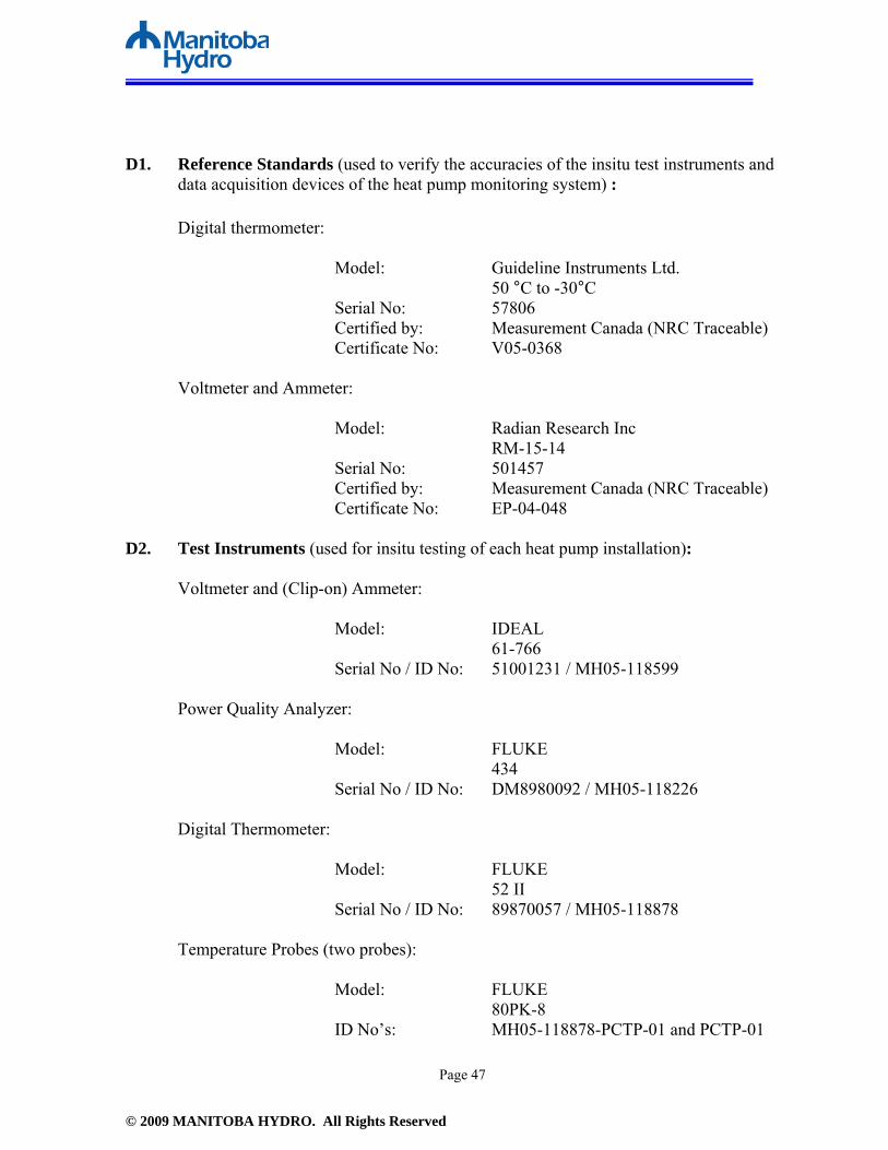
D1. Reference Standards (used to verify the accuracies of the insitu test instruments and
data acquisition devices of the heat pump monitoring system) : Digital thermometer: Model: Guideline Instruments Ltd. 50 °C to -30°C Serial No: 57806 Certified by: Measurement Canada (NRC Traceable) Certificate No: V05-0368 Voltmeter and Ammeter: Model: Radian Research Inc RM-15-14 Serial No: 501457 Certified by: Measurement Canada (NRC Traceable) Certificate No: EP-04-048 D2. Test Instruments (used for insitu testing of each heat pump installation): Voltmeter and (Clip-on) Ammeter: Model: IDEAL 61-766 Serial No / ID No: 51001231 / MH05-118599 Power Quality Analyzer: Model: FLUKE 434 Serial No / ID No: DM8980092 / MH05-118226 Digital Thermometer: Model: FLUKE 52 II Serial No / ID No: 89870057 / MH05-118878 Temperature Probes (two probes):
Model: FLUKE 80PK-8 ID No’s: MH05-118878-PCTP-01 and PCTP-01

© 2009 MANITOBA HYDRO. All Rights Reserved
Page 48
Appendix E
SCOP and SEER Calculation Constants

© 2009 MANITOBA HYDRO. All Rights Reserved
Page 49
D.1 Specific Heat for 25% Methanol: 25% Methanol SH = 0.95423 Btu/lb·F (3.995 kJ/kg·C)
D.2 Specific Gravity for 25% Methanol:
25% Methanol SG = 0.9678 (Confirmed by chemical analysis lab reports conducted on two samples of GL fluid)
D.3 Density of 25% Methanol:
Density 25% Methanol = 8.09 lb/USWG (0.97 kilogram/litre)
(8.34 lb/USG(density of water) x 0.97 S.G = 8.09 lb/USWG).
D.4 Ground Loop Flow Meter correction factor: for 25% Methanol:
Correction Factor = Flow Meter Reading x 1.02
Based on Dywer manufacturer’s correction formula: Q2 = Q1 x √1/S.G Where: Q2 = True Flow Value Q1 = Flow meter reading S.G = Specific Gravity of fluid
D.5 Specific Gravity of Water = 8.34 lb/USWG (1 kilogram/litre)
D.6 Specific Heat of Water = 1.0 Btu/lb·F (4.19 kJ/kg·C)

© 2009 MANITOBA HYDRO. All Rights Reserved
Page 50
Appendix F
Monthly Heat Pump Energy Data

© 2009 MANITOBA HYDRO. All Rights Reserved
Page 51
Electricity Usage (kWh)January
FebruaryMarch
AprilMay
JuneJuly
AugustSeptember
OctoberNovember
DecemberTotals
Total Heat Pump System1,802
1,898
1,106
642
322
269
436
293
308
532
944
1,168
9,720
Auxiliary Heater
46
210
56
44
-
-
-
-
8
-
42
-
406
Compressor Total1,022
991
600
334
161
124
203
112
127
275
650
922
5,525
Compressor Heating
1,022
991
600
311
111
20
-
8
83
266
650
922
4,985
Compressor Cooling-
-
-
23
51
105
203
105
44
9
-
-
539
FAN Total
204
205
135
98
75
88
113
92
90
114
156
186
1,556
FAN heating187
192
103
54
18
3
-
3
28
59
125
143
914
FAN Cooling
-
-
-
7
16
33
64
39
17
3
-
-
180
FAN Circulating17
13
33
37
41
51
49
58
58
53
31
43
484
Ground Loop Pump Total
487
466
302
175
98
88
145
79
75
150
297
324
2,687
Ground Loop Heating487
466
302
160
61
11
-
4
44
143
297
324
2,300
Ground Loop Pump Cooling
-
-
-
15
38
77
145
75
31
7
-
-
388
Desuperheater Pump Total45
29
32
18
11
10
15
9
9
18
35
46
277
Desuperheater Pump Heating
45
29
32
16
7
1
-
1
5
17
35
46
235
Desuperheater Pump Cooling-
-
-
2
4
9
15
8
3
1
-
-
42
DHW Tank Electricity Consumption
130
183
258
310
317
345
327
304
332
326
216
174
3,223
TotalsGround Loop Heat of Extraction (kWh)*
3,470
4,108
2,351
1,369
388
66
-
26
288
962
2,196
2,772
17,995
Ground Loop Heat of Rejection (Btu)*-
-
-
764,111
1,347,844
2,940,561
5,636,730
2,958,484
1,240,686
267,989
-
-
15,156,404
*Ground Loop Heat of Extraction and Heat of Rejection include loop pump electric powerWeighted Average
Average COP2.64
2.912.84
3.042.63
2.54N/A
N/A2.42
2.652.62
2.672.75
Average EERN/A
N/AN/A
15.511.7
12.212.0
12.112.3
12.8N/A
N/A12.2
Table # 1: House # 1 Monthly Heat Pump Data for 2007

© 2009 MANITOBA HYDRO. All Rights Reserved
Page 52
Electricity Usage (kWh)January
FebruaryMarch
AprilMay
JuneJuly
AugustSeptemberOctober
NovemberDecember
TotalsTotal Heat Pump System
1,996
1,820
1,221
453
93
218
729
331
526
560
1,263
1,929
11,139
Auxiliary Heater11
0
-
1
-
0
-
46
4
-
9
0
72
Compressor Total
1,532
1,401
913
344
68
151
520
201
449
428
954
1,474
8,435
Compressor Heating1,532
1,401
913
344
61
21
2
20
427
856
954
1,474
8,005
Compressor Cooling
-
-
-
0
7
130
518
181
22
-
-
-
858
FAN Total119
106
95
26
8
18
52
23
19
33
75
115
689
FAN heating
119
106
95
26
5
2
0
2
18
33
75
115
596
FAN Cooling-
-
-
0
2
16
52
19
1
-
-
-
90
FAN Circulating
0
0
(0)
0
1
0
0
3
0
0
0
-
4
Ground Loop Pump Total313
286
191
72
15
42
137
53
48
86
199
305
1,747
Ground Loop Heating
313
286
191
72
13
4
0
4
44
86
199
305
1,518
Ground Loop Pump Cooling-
-
-
0
2
38
136
49
3
-
-
-
229
Desuperheater Pump Total
32
27
24
9
2
6
20
8
7
13
26
34
208
Desuperheater Pump Heating32
27
24
9
2
1
0
1
6
13
26
34
174
Desuperheater Pump Cooling
-
-
-
0
0
6
20
7
0
-
-
-
34
TotalsGround Loop Heat of Extraction (kWh)*
4,126
3,849
2,526
959
205
83
4
77
728
1,342
2,473
2,914
19,287
Ground Loop Heat of Rejection (Btu)*-
-
-
412
166,193
2,864,155
10,360,466
3,784,009
252,843
-
-
-
17,428,079
*Ground Loop Heat of Extraction and Heat of Rejection include loop pump electric power
Weighted AverageAverage COP
2.93.0
2.93.0
3.43.8
2.52.0
2.42.3
2.82.4
2.7Average EER
N/AN/A
N/A10.8
14.013.7
12.113.2
7.7N/AN/A
N/A12.5
Table # 2: House # 2 Monthly Heat Pump Data for 2007

© 2009 MANITOBA HYDRO. All Rights Reserved
Page 53
Electricity Usage (kWh)January***February
MarchApril
MayJune
JulyAugust
SeptemberOctober
NovemberDecember
TotalsTotal Heat Pump System
4351,116
907327
21269
15270
147465
7621,049
5711Auxiliary Heater
00
00
00
00
00
00
0Compressor Total
300746
631234
15639
8943
99298
527732
3894Compressor Heating
300746
631234
15627
00
78296
527732
3727Compressor Cooling
00
00
013
8943
212
00
167FAN Total
2355
3413
415
3113
822
4056
314FAN heating
2355
3413
415
00
220
4056
261FAN Cooling
00
00
00
3113
60
00
51FAN Circulating
00
00
00
00
01
00
1Ground Loop Pump Total
65150
11541
2714
3013
1952
96137
759Ground Loop Heating
65150
11541
2714
00
1351
96137
710Ground Loop Pump Cooling
00
00
00
3013
60
00
49Desuperheater Pump Total
37
52
11
21
12
68
38Desuperheater Pump Heating
37
52
11
00
02
68
35Desuperheater Pump Cooling
00
00
00
21
00
00
3Primary Hydronic Pump
2048
4015
110
00
516
2843
226Zone Pumps
25110
8222
130
00
1576
6573
480**Used 2006 Data - Faulty temperature probe for part of 2007***Installed 12 January, 2006
TotalsGround Loop Heat of Extraction (kWh)*
9842,503
2,063703
431.0115
00
1661,141
1,9322,503
12539Ground Loop Heat of Rejection (Btu)*
00
00
0365,0522,555,3211,192,992
558,58747524
00
4719477*Ground Loop Heat of Extraction and Heat of Rejection include loop pump electric power
Weighted AverageAverage COP
3.113.10
3.143.01
2.902.76
0.000.00
2.353.36
3.403.25
3.17Average EER
0.00.0
0.00.0
0.025.3
15.116.4
16.515.2
0.00.0
16.1
Table # 3: House # 3 Heat Pump Data for 2006**

© 2009 MANITOBA HYDRO. All Rights Reserved
Page 54
Electricity Usage (kWh)January
FebruaryMarch
AprilMay
JuneJuly
AugustSeptember
OctoberNovember
December**Totals
Total Heat Pump System1162
448206
22398
254471
33391
284433
2224,227
Auxiliary Heater7
00
00
00
00
00
07
Compressor Total821
313141
15668
173322
24463
176266
1282,870
Compressor Heating821
313141
15648
00
013
176266
1282,062
Compressor Cooling0
00
020
173322
24450
00
0808
FAN Total48
3639
1915
3870
276
1536
39389
FAN heating40
2415
115
00
01
1526
27165
FAN Cooling0
00
02
3053
175
00
0108
FAN Circulating9
1124
88
917
100
010
11116
Ground Loop Pump Total259
9844
4922
5196
7121
83124
58976
Ground Loop Heating259
9844
4913
00
06
83124
58734
Ground Loop Pump Cooling0
00
07
5196
7115
00
0241
Desuperheater Pump Total36
136
72
00
01
1117
8101
Desuperheater Pump Heating36
136
72
00
01
1117
8100
Desuperheater Pump Cooling0
00
00
00
00
00
01
**2006 Data used - problem with downloading of data in 2007***December 1-15, 2006 Data
TotalsGround Loop Heat of Extraction (kWh)*
1,703583
268321
87N/AN/A
N/A43
581876
4044,866
Ground Loop Heat of Rejection (Btu)*0
00
004,525,3076,397,1734,813,960
1,089,5570
00
16,825,995*Ground Loop Heat of Extraction and Heat of Rejection include loop pump electric power
Weighted AverageAverage COP
2.252.11
2.142.25
2.12N/AN/A
N/A2.48
2.812.81
2.732.31
Average EERN/A
N/AN/A
N/AN/A
15.110.9
11.912.9N/A
N/AN/A
11.9
Table # 4: House # 4 Monthly Heat Pump Data for 2006***

© 2009 MANITOBA HYDRO. All Rights Reserved
Page 55
Heat Pump Usage (kWh)January
FebruaryMarch
AprilMay***
June***July
AugustSeptemberOctoberNovember
DecemberTotalsTotal Heat Pump System
2,6692,399
1,393904
599171
367146
180483
9652,034
12,309Auxiliary Heater
407386
2824
180
00
21
163
929Compressor Total
1,6301,448
989639
415109
23895
132350
7061,437
8,186Compressor Heating
1,6301,448
989639
40826
00
129350
7061,437
7,759Compressor Cooling
00
00
784
23895
40
0427
FAN Total370
332220
14188
3378
3127
77152
3111,860
FAN heating370
332220
14185
50
026
77152
3111,720
FAN Cooling0
00
02
2878
311
00
0140
FAN Circulating0
00
00
00
00
00
00
Ground Loop Pump Total263
234156
10062
2252
2119
54106
2221,311
Ground Loop Heating263
234156
10060
40
018
54106
2221,218
Ground Loop Pump Cooling0
00
02
1952
211
00
094
Desuperheater Pump Total**0
00
016
60
00
00
023
Desuperheater Pump Heating0
00
016
10
00
00
017
Desuperheater Pump Cooling0
00
00
50
00
00
06
**DSH disconnected***2006 Data:Communication Failed
TotalsGround Loop Heat of Extraction (kWh)*
5,6374644
2,7241,761
1,34673
N/AN/A
289883
1,7984,278
23,434Ground Loop Heat of Rejection (Btu)*
00
00
145,1401,813,8754,019,5861,499,42543,080
00
07,521,105
*Ground Loop Heat of Extraction and Heat of Rejection include loop pump electric powerWeighted Average
Average COP3.01
2.842.84
2.843.19
2.94N/A
N/A2.55
2.722.75
2.992.91
Average EERN/A
N/AN/A
N/A10
118
75N/A
N/AN/A
8
Table # 5: House # 5 Monthly Heat Pump Data for 2007

© 2009 MANITOBA HYDRO. All Rights Reserved
Page 56
Heat Pump Usage (kWh)January
FebruaryMarch
AprilMay
JuneJuly
AugustSeptemberOctober
NovemberDecemberTotalsTotal Heat Pump System
2,3372,295
1,6961,059
503286
485466
548786
1,4552,440
14,356Auxiliary Heater
00
00
00
00
00
00
0Compressor Total
1,6141,578
1,095663
289137
261265
320474
9171,625
9,238Compressor Heating
1,6141,578
1,095663
28958
333
208456
9171,625
8,539Compressor Cooling
00
00
079
258232
11218
00
698FAN Total
349342
301212
132108
146131
148196
306419
2,790FAN heating
337336
284182
8221
17
59143
277408
2,136FAN Cooling
00
00
029
8567
387
00
226FAN Circulating
127
1630
5058
6057
5146
2911
428Ground Loop Pump Total
336343
250148
6333
6358
6594
191346
1,993Ground Loop Heating
336343
250148
6312
16
3990
191346
1,826Ground Loop Pump Cooling
00
00
021
6352
264
00
167Desuperheater Pump Total
3832
5036
197
1411
1422
4150
335Desuperheater Pump Heating
3832
5036
193
01
821
4150
299Desuperheater Pump Cooling
00
00
04
1411
61
00
36
TotalsGround Loop Heat of Extraction (kWh)*
5,8275,727
3,9742,404
1,049208
14138
8981,979
3,7035,985
31,906Ground Loop Heat of Rejection (Btu)*
00
00
02,457,275
7,303,6715,449,659
2,756,938476,925
00
18,444,468*Ground Loop Heat of Extraction and Heat of Rejection include loop pump electric power
Weighted AverageAverage COP
3.353.34
3.193.16
3.143.05
3.563.80
3.703.63
3.433.30
3.33Average EER
N/AN/A
N/AN/A
N/A16.5
15.412.7
13.013.9N/A
N/A14.2
Table # 6: House # 6 Monthly Heat Pump Data for 2007

© 2009 MANITOBA HYDRO. All Rights Reserved
Page 57
Heat Pump Usage (kWh)January
FebruaryMarch
AprilMay
JuneJuly
AugustSeptember
OctoberNovemberDecemberTotals
Total Heat Pump System1,948
2,0551,308
767376
87388
74330
6091,292
2,06511,298
Auxiliary Heater7
00
00
00
00
00
07
Compressor Total1,330
1,416899
526258
54242
46230
423895
1,4227,739
Compressor Heating1,330
1,416899
526258
140
0221
423895
1,4227,402
Compressor Cooling0
00
00
40242
469
00
0337
FAN Total297
305193
11255
1670
1348
88192
3001,688
FAN heating293
305193
11255
30
045
88192
3001,585
FAN Cooling0
00
00
1370
133
00
098
FAN Circulating4
00
00
00
00
00
04
Ground Loop Pump Total307
332204
11857
1568
1348
88199
3421,793
Ground Loop Heating307
332204
11857
30
046
88199
3421,696
Ground Loop Pump Cooling0
00
00
1368
133
00
097
Desuperheater Pump Total8
212
106
28
25
106
171
Desuperheater Pump Heating8
212
106
00
04
106
160
Desuperheater Pump Cooling0
00
00
18
20.3
00
012
TotalsGround Loop Heat of Extraction (kWh)*
40674543
28241604
75942
00
6461209
22963204
21,194Ground Loop Heat of Rejection (Btu)*
00
00
02,457,2757,303,6715,449,6592,756,938
476,9250
018,444,468
*Ground Loop Heat of Extraction and Heat of Rejection include loop pump electric powerWeighted Average
Average COP2.93
3.053.00
2.942.87
2.95N/A
N/A2.90
2.842.62
2.392.81
Average EERN/A
N/AN/A
N/AN/A
10.289.60
11.139.57N/A
N/AN/A
9.89
Table # 7: House # 7 Monthly Heat Pump Data for 2007

© 2009 MANITOBA HYDRO. All Rights Reserved
Page 58
Heat Pump Usage (kWh)January
FebruaryMarchApril
MayJune
JulyAugust
SeptemberOctoberNovember
DecemberTotalsTotal Heat Pump System
2,2622,359
1,578831
336166
416185
245710
1,4332,362
12,884Auxiliary Heater
2983
4772
50
00
05
335
280Compressor Total
1,3511,389
901437
18173
20585
130404
8521,411
7,417Compressor Heating
1,3511,389
901433
1536
00
117403
8521,411
7,016Compressor Cooling
00
04
2767
20585
131
00
401FAN Total
366418
232112
5642
6945
4795
183380
2,046FAN heating
363416
22494
251
01
2277
171376
1,770FAN Cooling
00
01
817
4820
30.1
00
98FAN Circulating
32
816
2324
2024
2317
124
177Ground Loop Pump Total
455415
348183
8344
12548
59181
347475
2,764Ground Loop Heating
455415
348181
692
00
51181
347475
2,526Ground Loop Pump Cooling
00
02
1442
12548
80.4
00
238Desuperheater Pump Total
6153
4926
126
187
826
4961
376Desuperheater Pump Heating
6153
4926
100.3
00
726
4961
342Desuperheater Pump Cooling
00
00
26
187
10.0
00
34
TotalsGround Loop Heat of Extraction (kWh)*
2,5482,755
1,687787
24112
00
209677
1,4272,517
12,860Ground Loop Heat of Rejection (Btu)*
00
054,057
908,2922,824,635
8,321,4383,175,225450,375
11,0340
015,745,056
*Ground Loop Heat of Extraction and Heat of Rejection include loop pump electric powerWeighted Average
Average COP1.90
1.971.82
1.721.62
2.05N/A
N/A1.76
1.681.73
1.841.84
Average EERN/A
N/AN/A
5.316.8
21.420.4
19.518.3
7.3N/A
N/A19.9
Table # 8: House # 8 Monthly Heat Pump Data for 2007

© 2009 MANITOBA HYDRO. All Rights Reserved
Page 59
Heat Pump Usage (kWh)January
FebruaryMarch
AprilMay
JuneJuly
AugustSeptemberOctober
NovemberDecember
TotalsTotal Heat Pump System
1,0401,038
710275
167165
24082
148266
527941
5,599Auxiliary Heater
00
00
00
00
00
00
0Compressor Total
771782
526204
9577
12931
67162
378709
3,932Compressor Heating
771782
526204
8811
00
55162
378709
3,686Compressor Cooling
00
00
764
12931
120
00
244FAN Total
104101
7428
5265
7542
6670
7187
837FAN heating
9598
7027
121
00
721
4778
457FAN Cooling
00
00
112
236
20
00
44FAN Circulating
93
51
3951
5236
5749
249
336Ground Loop Pump Total
126119
8433
1617
277
1126
59110
635Ground Loop Heating
126119
8433
152
00
926
59110
581Ground Loop Pump Cooling
00
00
115
277
30
00
53Desuperheater Pump Total
3936
2610
4.85.2
8.42.1
3.48
1834
195Desuperheater Pump Heating
3936
2610
4.40.5
0.00.0
2.68
1834
178Desuperheater Pump Cooling
00
00
0.44.5
8.42.1
0.80
00
16
TotalsGround Loop Heat of Extraction (kWh)*
2,6032,632
1,802721
33742
00
245694
1,5232,243
12,842Ground Loop Heat of Rejection (Btu)*
00
00
202,3642,009,2483,627,434912,176
335,8240
00
7,087,046*Ground Loop Heat of Extraction and Heat of Rejection include loop pump electric power
Weighted AverageAverage COP
3.403.43
3.443.51
3.713.81
N/AN/A
4.244.09
3.913.29
3.50Average EER
N/AN/A
N/A5.3
16.821.4
20.419.5
18.37.3
N/AN/A
19.9
Table # 9: House # 9 Monthly Heat Pump Data for 2007

© 2009 MANITOBA HYDRO. All Rights Reserved
Page 60
Heat Pump Usage (kWh)January
FebruaryMarch
AprilMay
JuneJuly
AugustSeptemberOctober
November**December**TotalsTotal Heat Pump System
2,1302,019
1,371605
235266
310133
177548
1,3331,697
10,824Auxiliary Heater
76119
00
00
00
00
00
195Compressor Total
1,4811,368
986436
155155
19980
98399
9611,219
7,535Compressor Heating
1,4811,368
986436
13615
00
98399
9611,219
7,097Compressor Cooling
00
00
19140
19980
00
00
438FAN Total
320295
21092
5278
7036
6382
207266
1,772FAN heating
320295
21092
313
00
1982
207266
1,526FAN Cooling
00
00
648
5722
00
00
132FAN Circulating
00
00
1527
1314
440
00
114Ground Loop Pump Total
222208
14966
2428
3514
1458
141182
1,140Ground Loop Heating
222208
14966
202
00
1458
141182
1,062Ground Loop Pump Cooling
00
00
426
3514
00
00
78Desuperheater Pump Total
3230
2511
4.14.9
62
210
2430
182Desuperheater Pump Heating
3230
2511
3.50.4
00
210
2430
169Desuperheater Pump Cooling
00
00
0.64.5
62
00
00
14**2006 Data:Temperature Probe Failed
TotalsGround Loop Heat of Extraction (kWh)*
45014091
28971288
34940
00
2691159
27273793
21,115Ground Loop Heat of Rejection (Btu)*
00
00
457,8413,423,369
4,520,9591,753,028
00
00
10,155,197*Ground Loop Heat of Extraction and Heat of Rejection include loop pump electric power
Weighted AverageAverage COP
3.012.92
3.003.02
2.722.80
N/AN/A
2.913.01
2.943.13
3.00Average EER
N/AN/A
N/AN/A
N/A13.5
13.212.8
N/AN/A
N/AN/A
13.0
Table # 10: House # 10 Monthly Heat Pump Data for 2007

© 2009 MANITOBA HYDRO. All Rights Reserved
Page 61
Appendix G
Domestic Hot Water Data

© 2009 MANITOBA HYDRO. All Rights Reserved
Page 62
AB
CD
EF
GH
IJ
K
House
Average Water Heater Inlet Temperature (degrees Celsius)
Average Water Heater Outlet Temperature (degrees Celsius)
Hot Water Usage (litres)
Energy delivered to water usage
(kWh)
Calculated Stand-By
Loss (kWh)
Total Hot Water Energy (kWh) E + F
Hot Water Heater
Electricity Usage (kWh)
Energy provided by Desuperheater (kWh)
G-H
Electric Energy to
Heat Pump (kWh)*
Net energy savings (kWh)
I-J1
7.555.5
557763105
17974901
32231678
5691109
216.6
53.550954
21851865
40502260
1790649
11423
15.349.6
457791834
21343967
3057910
260650
413.6
49.930176
12742448
37213334
388153
2355
12.944.0
23088831
12112042
20420
00
612.8
52.543294
1995909
29032224
679216
4637
14.450.0
472221950
11553105
2805301
98202
815.2
58.461728
3097757
38542521
1333748
5859
14.646.0
464761700
11012800
16921109
272836
1012.1
48.855169
2352927
32792026
1254396
879Average
13.550.8
459662032
14303462
2518944
336610
*Electric energy to heat pump in cooling mode is the electric energy to the desuperheater pump only.
Table # 11: Annual Domestic Hot Water Data for Monitored Houses
*Electric energy to heat pump in heating mode is the energy provided by the desuperheater divided by the COP of the heat pump system. The heat pump runs longer to satisfy the home's heating requirements since its heating capacity was reduced by the desuperheater.

© 2009 MANITOBA HYDRO. All Rights Reserved
Page 63
Table 12: Domestic Hot Water Data for House # 1
A B C D E F G H I J K
Month
Average Water Heater Inlet
Temperature (degrees Celsius)
Average Water Heater Outlet Temperature
(degrees Celsius)
Hot Water Usage (litres)
Energy delivered to water usage
(kWh)
Calculated Stand-By
Loss (kWh)
Total Hot Water Energy
(kWh) E + F
Hot Water Heater
Electricity Usage (kWh)
Energy provided by Desuperheater (kWh)
G-H
Electric Energy to
Heat Pump (kWh)*
Net energy savings (kWh)
I-JJanuary 6.9 55.2 4629 260 153 412 130 282 107 176February 6.9 56.4 4560 262 138 400 183 216 74 142March 7.0 54.6 5334 295 153 447 258 189 66 123April 6.9 55.1 5166 289 148 436 310 126 39 87May 7.3 56.1 4282 242 153 395 317 77 23 55June 8.2 57.2 4449 253 148 400 345 55 12 43July 7.5 55.6 4340 242 153 395 327 68 18 50August 8.5 55.8 3840 211 153 363 304 59 8 51September 8.3 57.1 4560 258 148 406 332 74 22 52October 8.1 55.2 4827 264 153 417 326 90 33 57November 7.4 52.5 4546 238 148 386 216 170 65 105December 7.1 55.2 5243 292 153 445 174 271 101 169Annual 7.5 55.5 55776 3105 1797 4901 3223 1678 569 1109
House # 1 Domestic Hot Water Data
Table 13: Domestic Hot Water Data for House # 2
A B C D E F G H I J K
Month
Average Water Heater Inlet
Temperature (degrees Celsius)
Average Water Heater Outlet Temperature
(degrees Celsius)
Hot Water Usage (litres)
Energy delivered to water usage
(kWh)
Calculated Stand-By
Loss (kWh)
Total Hot Water Energy
(kWh) E + F
Hot Water Heater
Electricity Usage (kWh)
Energy provided by Desuperheater (kWh)
G-H
Electric Energy to
Heat Pump (kWh)*
Net energy savings (kWh)
I-JJanuary 16.8 53.8 3554 153 158 311 60 251 86 164February 16.8 53.8 3528 152 143 295 62 233 79 154March 15.9 53.1 4806 208 158 366 174 192 66 126April 15.1 52.4 5008 217 153 370 264 106 36 70May 15.6 53.3 5160 226 158 385 352 33 9 24June 17.5 56.6 4718 214 153 367 319 49 7 42July 18.9 53.8 4312 175 158 333 300 33 20 12August 18.8 53.9 3254 133 158 291 229 62 10 52September 16.9 51.6 4111 165 153 319 201 117 47 71October 15.9 51.3 4027 166 158 324 165 159 70 89November 17.6 53.5 3949 164 153 318 73 245 87 157December 13.9 54.6 4527 214 158 372 61 311 132 179Annual 16.6 53.5 50954 2185 1865 4050 2260 1790 649 1142
House # 2 Domestic Hot Water Data

© 2009 MANITOBA HYDRO. All Rights Reserved
Page 64
Table 14: Domestic Hot Water Data for House # 3
A B C D E F G H I J K
Month
Average Water Heater Inlet
Temperature (degrees Celsius)
Average Water Heater Outlet Temperature
(degrees Celsius)
Hot Water Usage (litres)
Energy delivered to water usage
(kWh)
Calculated Stand-By
Loss (kWh)
Total Hot Water Energy
(kWh) E + F
Hot Water Heater
Electricity Usage (kWh)
Energy provided by Desuperheater (kWh)
G-H
Electric Energy to
Heat Pump (kWh)*
Net energy savings (kWh)
I-JJanuary 14.0 46.1 1929 72 181 253 81 172 55 117February 13.0 48.5 4752 196 164 359 220 139 45 94March 12.4 53.9 5071 244 181 425 347 78 25 53April 12.9 49.7 3423 146 175 322 294 28 9 19May 15.2 53.1 3728 164 181 345 312 34 12 22June 14.9 49.2 3511 140 175 315 300 15 5 9July 16.8 48.8 3956 147 181 328 296 32 0 32August 17.7 49.7 3968 147 181 329 291 38 0 38September 17.1 50.5 4155 161 175 336 281 55 13 42October 17.7 48.8 3911 141 181 322 240 83 24 58November 16.5 48.3 3662 135 175 310 198 112 33 79December 15.5 48.1 3713 140 181 322 198 124 38 86Annual 15.3 49.6 45779 1834 2134 3967 3057 910 260 650
House # 3 Domestic Hot Water Data
Table 15: Domestic Hot Water Data for House # 4
A B C D E F G H I J K
Month
Average Water Heater Inlet
Temperature (degrees Celsius)
Average Water Heater Outlet Temperature
(degrees Celsius)
Hot Water Usage (litres)
Energy delivered to water usage
(kWh)
Calculated Stand-By
Loss (kWh)
Total Hot Water Energy
(kWh) E + F
Hot Water Heater
Electricity Usage (kWh)
Energy provided by Desuperheater (kWh)
G-H
Electric Energy to
Heat Pump (kWh)*
Net energy savings (kWh)
I-JJanuary 11.9 51.1 2403 109 208 317 264 53 23 29February 14.9 49.6 2282 92 188 279 228 51 24 27March 15.7 50.1 2421 96 208 304 239 66 31 35April 11.9 49.7 2571 113 201 314 309 5 2 3May 12.8 49.4 2810 120 208 327 326 1 1 1June 14.4 48.7 2399 96 201 297 295 2 0.2 1July 13.1 49.5 3376 143 208 351 341 10 0.4 9August 13.5 50.5 2878 123 208 331 319 12 0.3 12September 14.1 50.0 3226 134 201 336 314 22 8 14October 12.7 49.4 2590 110 213 323 323 0 0 0November 13.6 50.6 2277 98 201 299 269 30 11 19December 14.3 50.8 943 40 208 248 107 141 52 89Annual 13.6 49.9 30176 1274 2448 3721 3334 388 153 235
House # 4 Domestic Hot Water Data

© 2009 MANITOBA HYDRO. All Rights Reserved
Page 65
Table 16: Domestic Hot Water Data for House # 5
A B C D E F G H I J K
Month
Average Water Heater Inlet
Temperature (degrees Celsius)
Average Water Heater Outlet Temperature
(degrees Celsius)
Hot Water Usage (litres)
Energy delivered to water usage
(kWh)
Calculated Stand-By
Loss (kWh)
Total Hot Water Energy
(kWh) E + F
Hot Water Heater
Electricity Usage (kWh)
Energy provided by Desuperheater (kWh)
G-H
Electric Energy to
Heat Pump (kWh)*
Net energy savings (kWh)
I-JJanuary 11.2 40.0 1546 52 119 171 171 0 0 0February 10.6 40.8 1447 51 110 160 160 0 0 0March 12.1 42.4 1801 63 114 178 178 0 0 0April 12.3 41.7 1972 67 112 180 180 0 0 0May 11.1 47.9 2067 88 87 175 175 0 0 0June 14.5 44.5 2086 73 87 160 160 0 0 0July 14.2 46.1 1817 67 92 159 159 0 0 0August 15.7 46.5 1874 67 94 161 161 0 0 0September 13.2 45.4 3202 120 104 224 224 0 0 0October 14.6 46.4 1552 57 83 140 140 0 0 0November 13.4 45.6 1900 71 89 160 160 0 0 0December 12.4 40.2 1824 59 116 175 175 0 0 0Annual 12.9 44.0 23088 831 1211 2042 2042 0 0 02006 DataThe desuperheater pump failed on this unit and was not replaced.
House # 5 Domestic Hot Water Data
Table 17: Domestic Hot Water Data for House # 6
A B C D E F G H I J K
Month
Average Water Heater Inlet
Temperature (degrees Celsius)
Average Water Heater Outlet Temperature
(degrees Celsius)
Hot Water Usage (litres)
Energy delivered to water usage
(kWh)
Calculated Stand-By
Loss (kWh)
Total Hot Water Energy
(kWh) E + F
Hot Water Heater
Electricity Usage (kWh)
Energy provided by Desuperheater (kWh)
G-H
Electric Energy to
Heat Pump (kWh)*
Net energy savings (kWh)
I-JJanuary 10.8 52.6 2902 141 77 218 138 79 24 56February 11.0 52.6 2467 119 70 189 130 59 18 41March 10.6 53.6 2977 148 77 226 148 78 24 53April 13.0 50.0 2132 92 75 166 128 38 12 26May 13.3 49.6 2117 89 77 166 131 35 11 24June 12.8 49.5 2539 108 75 183 170 13 6 7July 14.6 55.0 3667 172 77 249 221 28 14 14August 14.2 54.1 5745 266 77 343 331 12 11 1September 16.2 51.3 4299 175 75 250 215 35 11 23October 15.2 50.5 6009 246 77 323 220 103 28 75November 12.1 53.0 3006 142 75 217 157 60 17 42December 9.7 55.1 5434 286 77 363 234 130 39 90Annual 12.8 52.5 43294 1995 909 2903 2224 679 216 463
House # 6 Domestic Hot Water Data

© 2009 MANITOBA HYDRO. All Rights Reserved
Page 66
Table 18: Domestic Hot Water Data for House # 7
A B C D E F G H I J K
Month
Average Water Heater Inlet
Temperature (degrees Celsius)
Average Water Heater Outlet Temperature
(degrees Celsius)
Hot Water Usage (litres)
Energy delivered to water usage
(kWh)
Calculated Stand-By
Loss (kWh)
Total Hot Water Energy
(kWh) E + F
Hot Water Heater
Electricity Usage (kWh)
Energy provided by Desuperheater (kWh)
G-H
Electric Energy to
Heat Pump (kWh)*
Net energy savings (kWh)
I-JJanuary 13.3 49.0 4694 195 98 293 221 72 24 47February 13.0 49.5 2936 124 89 213 177 36 12 24March 12.0 49.0 1932 83 98 181 130 51 17 34April 11.9 49.6 4424 194 95 289 279 10 3 6May 13.4 50.6 4540 196 98 294 288 6 2 4June 17.3 53.0 4349 180 95 275 267 9 2 7July 15.1 49.4 3785 151 98 249 237 12 8 4August 15.8 49.6 3928 154 98 252 221 31 2 30September 16.5 50.0 3358 131 95 226 204 21 7 14October 16.1 50.0 4859 192 98 290 280 10 3 6November 15.2 49.2 3788 149 95 244 223 21 8 13December 13.3 50.9 4629 202 98 300 278 22 9 13Annual 14.4 50.0 47222 1950 1155 3105 2805 301 98 202
House # 7 Domestic Hot Water Data
Table 19: Domestic Hot Water Data for House # 8
A B C D E F G H I J K
Month
Average Water Heater Inlet
Temperature (degrees Celsius)
Average Water Heater Outlet Temperature
(degrees Celsius)
Hot Water Usage (litres)
Energy delivered to water usage
(kWh)
Calculated Stand-By
Loss (kWh)
Total Hot Water Energy
(kWh) E + F
Hot Water Heater
Electricity Usage (kWh)
Energy provided by Desuperheater (kWh)
G-H
Electric Energy to
Heat Pump (kWh)*
Net energy savings (kWh)
I-JJanuary 16.7 59.1 4851 239 64 303 133 171 96 74February 16.5 58.7 4720 231 58 289 120 170 91 78March 15.0 58.4 5336 269 64 333 167 165 97 68April 14.0 59.0 5146 269 62 331 237 94 61 33May 13.4 56.5 5391 270 64 334 271 63 40 22June 13.2 57.9 5929 307 62 369 328 41 7 34July 15.9 59.3 5855 295 64 359 297 62 18 44August 15.4 58.7 4685 236 64 300 268 32 7 25September 15.2 58.2 3917 195 62 257 217 41 27 14October 16.3 58.7 4988 246 64 310 202 108 72 37November 15.7 58.0 5080 250 62 312 148 164 102 62December 15.0 58.8 5830 296 64 360 134 226 129 97Annual 15.2 58.4 61728 3097 757 3854 2521 1333 748 585
House # 8 Domestic Hot Water Data

© 2009 MANITOBA HYDRO. All Rights Reserved
Page 67
Table 20: Domestic Hot Water Data for House # 9
A B C D E F G H I J K
Month
Average Water Heater Inlet
Temperature (degrees Celsius)
Average Water Heater Outlet Temperature
(degrees Celsius)
Hot Water Usage (litres)
Energy delivered to water usage
(kWh)
Calculated Stand-By
Loss (kWh)
Total Hot Water Energy
(kWh) E + F
Hot Water Heater
Electricity Usage (kWh)
Energy provided by Desuperheater (kWh)
G-H
Electric Energy to
Heat Pump (kWh)*
Net energy savings (kWh)
I-JJanuary 14.1 44.6 3873 137 93 231 92 138 41 98February 13.9 43.8 2511 87 84 172 64 107 31 76March 14.2 46.0 4005 148 93 241 115 126 37 89April 13.2 46.0 4637 176 90 267 171 96 27 69May 13.4 45.4 4485 167 93 260 193 68 17 50June 19.0 51.9 4472 171 90 261 207 54 6 48July 14.3 45.4 4122 149 93 242 170 72 8 64August 15.5 45.3 3180 110 93 203 150 53 2 51September 15.5 43.7 3792 124 90 214 153 61 12 49October 15.0 45.9 4174 149 93 243 159 84 21 64November 14.4 46.7 3663 137 90 228 116 112 29 83December 12.3 47.4 3562 145 93 238 101 137 42 96Annual 14.6 46.0 46476 1700 1101 2800 1692 1109 272 836
House # 9 Domestic Hot Water Data
Table 21: Domestic Hot Water Data for House # 10
A B C D E F G H I J K
Month
Average Water Heater Inlet
Temperature (degrees Celsius)
Average Water Heater Outlet Temperature
(degrees Celsius)
Hot Water Usage (litres)
Energy delivered to water usage
(kWh)
Calculated Stand-By
Loss (kWh)
Total Hot Water Energy
(kWh) E + F
Hot Water Heater
Electricity Usage (kWh)
Energy provided by Desuperheater (kWh)
G-H
Electric Energy to
Heat Pump (kWh)*
Net energy savings (kWh)
I-JJanuary 10.5 50.6 4349 202 79 281 70 211 70 141February 9.4 50.3 4637 220 71 292 84 207 71 136March 9.0 48.8 4343 200 79 279 136 143 48 96April 9.0 47.7 5043 226 76 302 239 64 21 43May 11.0 47.6 5382 229 79 308 293 14 5 9June 12.8 48.4 4908 203 76 279 267 13 5 8July 15.8 47.7 1689 63 79 141 119 22 6 16August 17.3 49.1 4979 184 79 262 231 31 2 28September 16.5 47.9 4209 153 76 230 199 31 11 20October 14.6 47.5 4862 186 79 264 210 54 18 36November 10.4 49.1 5381 242 76 318 173 145 67 78December 8.9 51.4 5387 265 79 344 4 340 72 268Annual 12.1 48.8 55169 2352 927 3279 2026 1254 396 879
House # 10 Domestic Hot Water Data

© 2009 MANITOBA HYDRO. All Rights Reserved
Page 68
Appendix H
Run Hours and Starts Data

© 2009 MANITOBA HYDRO. All Rights Reserved
Page 69
House January
FebruaryMarch
AprilMay
JuneJuly
AugustSeptemberOctober
NovemberDecemberTotalsTotal
578518
392229
138126
199113
105212
402399
3,410Stage 1
370260
321191
135125
184112
101209
364288
2,660Stage 2
208258
7138
31
151
43
38111
7502
476438
289109
2365
20880
68128
283329
2,4973
115266
20474
925
5323
3349
171244
1266Total
394149
6775
3379
150110
32123
18889
1,488Stage 1
385149
6774
3052
10473
22123
18788
1,354Stage 2
90
01
327
4636
100
11
1345
607540
358229
14854
12047
44125
247512
3,032Total
609599
567391
20180
150122
160242
398618
4,137Stage 1
235189
408335
19957
10164
117196
290306
2,498Stage 2
375410
15956
123
4958
4246
107312
1,6407
392428
265153
7421
9217
63117
253408
2,282Total
660603
510270
12365
18671
88270
384637
3,867Stage 1
423282
393237
11661
18166
86266
323394
2,830Stage 2
236321
11733
84
54
23
61243
1,0379
475491
348135
6570
11429
46106
236392
2,50710
529494
355156
5870
8734
33139
338435
2,728
Average Run Hours483
453336
18287
65136
6567
151290
4062721
413409
276140
6351
10749
51111
232353
2254
Two Stage Heat Pump: First stage provides 50% output capacity of second stage Two Stage Heat Pump: First stage provides 70% output capacity of second stage. First stage and second stage run hours were not seperated.
8
Table 22: Heat Pump Annual Run-Hours
146
Average Equivalent Full Load Run Hours
Average Equivalent Full Load Run Hours is equal to stage # 1 run hours/percent of full load capacity plus stage # 2 run hours

© 2009 MANITOBA HYDRO. All Rights Reserved
Page 70
Table 23: Heat Pump Run Hours (Heating Mode)
January February March April May June July August September October November December TotalsTotal 578 518 392 210 85 16 0 6 62 203 402 399 2870Stage 1 370 260 321 174 82 16 0 6 60 200 364 288 2,140Stage 2 208 258 71 36 3 0 0 0 2 3 38 111 730
2 476 438 289 109 19 7 1 6 63 128 283 329 2,1483 115 266 204 74 47 17 0 0 23 48 171 244 1210
Total 394 149 67 75 22 0 0 0 9 123 188 89 1114Stage 1 385 149 67 74 20 0 0 0 8 123 187 88 1,101Stage 2 9 0 0 1 2 0 0 0 0 0 1 1 14
5 607 540 358 229 144 9 0 0 42 125 247 512 2,815Total 609 599 567 391 201 32 2 12 96 231 398 618 3,757Stage 1 235 189 408 335 199 27 2 6 73 188 290 306 2,257Stage 2 375 410 159 56 1 6 0 6 24 44 107 312 1,499
7 392 428 265 153 74 4 0 0 60 117 253 408 2,153Total 659 603 510 267 103 3 0 2 76 269 384 637 3515Stage 1 423 282 393 234 99 2 0 2 75 266 323 394 2,494Stage 2 236 321 117 33 4 1 0 0 2 3 61 243 1,021
9 475 491 348 135 60 7 0 0 36 106 236 392 2,28610 529 494 355 156 49 5 0 0 33 139 338 435 2,534
483 453 336 180 80 10 0 3 50 149 290 406 2440413 409 276 139 60 8 0 2 39 110 232 353 2041
AverageAverage Equivalent Full Load Run Hours
House Heat Pump Run Hours (Heating Mode)
1
4
6
8
Table 24: Heat Pump Run Hours (Cooling Mode)
January February March April May June July August September October November December TotalsTotal 0 0 0 19 54 110 199 107 43 9 0 0 541Stage 1 0 0 0 17 53 110 184 106 41 9 0 0 520Stage 2 0 0 0 2 1 1 15 1 1 0 0 0 20
2 0 0 0 0 4 58 207 74 5 0 0 0 3483 0 0 0 0 0 8 53 23 11 1 0 0 94
Total 0 0 0 0 11 79 150 110 23 0 0 0 373Stage 1 0 0 0 0 10 52 104 73 14 0 0 0 253Stage 2 0 0 0 0 1 27 46 36 10 0 0 0 120
5 0 0 0 0 4 45 120 47 2 0 0 0 218Total 0 0 0 0 0 48 148 110 63 11 0 0 380Stage 1 0 0 0 0 0 30 99 57 44 9 0 0 240Stage 2 0 0 0 0 0 18 49 53 19 3 0 0 140
7 0 0 0 0 0 17 92 17 3 0 0 0 130Total 0 0 0 3 20 63 186 69 11 0 0 0 352Stage 1 0 0 0 3 16 60 181 64 11 0 0 0 336Stage 2 0 0 0 0 4 3 5 4 0 0 0 0 16
9 0 0 0 0 5 62 114 29 11 0 0 0 22110 0 0 0 0 9 65 87 34 0 0 0 0 195
0 0 0 2 11 55 135 62 17 2 0 0 2850 0 0 1 7 43 107 47 12 1 0 0 218Average Equivalent Full Load Run Hours
8
Average
Heat Pump Run Hours (Cooling Mode)House
4
6
1
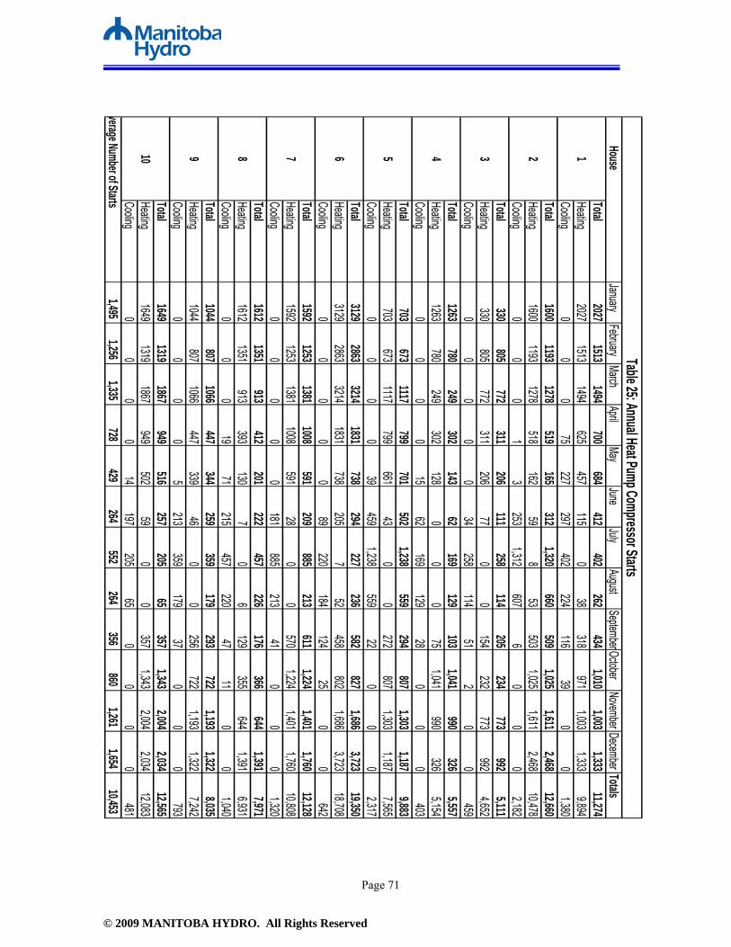
© 2009 MANITOBA HYDRO. All Rights Reserved
Page 71
House January
FebruaryMarch
AprilMay
JuneJuly
AugustSeptemberOctober
NovemberDecember TotalsTotal
20271513
1494700
684412
402262
4341,010
1,0031,333
11,274Heating
20271513
1494625
457115
038
318971
1,0031,333
9,894Cooling
00
075
227297
402224
11639
00
1,380Total
16001193
1278519
165312
1,320660
5091,025
1,6112,468
12,660Heating
16001193
1278518
16259
853
5031,025
1,6112,468
10,478Cooling
00
01
3253
1,312607
60
00
2,182Total
330805
772311
206111
258114
205234
773992
5,111Heating
330805
772311
20677
00
154232
773992
4,652Cooling
00
00
034
258114
512
00
459Total
1263780
249302
14362
169129
1031,041
990326
5,557Heating
1263780
249302
1280
00
751,041
990326
5,154Cooling
00
00
1562
169129
280
00
403Total
703673
1117799
701502
1,238559
294807
1,3031,187
9,883Heating
703673
1117799
66143
00
272807
1,3031,187
7,565Cooling
00
00
39459
1,238559
220
00
2,317Total
31292863
32141831
738294
227236
582827
1,6863,723
19,350Heating
31292863
32141831
738205
752
458802
1,6863,723
18,708Cooling
00
00
089
220184
12425
00
642Total
15921253
13811008
591209
885213
6111,224
1,4011,760
12,128Heating
15921253
13811008
59128
00
5701,224
1,4011,760
10,808Cooling
00
00
0181
885213
410
00
1,320Total
16121351
913412
201222
457226
176366
6441,391
7,971Heating
16121351
913393
1307
06
129355
6441,391
6,931Cooling
00
019
71215
457220
4711
00
1,040Total
1044807
1066447
344259
359179
293722
1,1931,322
8,035Heating
1044807
1066447
33946
00
256722
1,1931,322
7,242Cooling
00
00
5213
359179
370
00
793Total
16491319
1867949
516257
20565
3571,343
2,0042,034
12,565Heating
16491319
1867949
50259
00
3571,343
2,0042,034
12,083Cooling
00
00
14197
20565
00
00
481verage Number of Starts
1,495
1,256
1,335
728
429
264
552
264
356
860
1,261
1,654
10,453
78910
Table 25: Annual Heat Pump Compressor Starts
123456

© 2009 MANITOBA HYDRO. All Rights Reserved
Page 72
Appendix I
Entering Fluid Temperature Data

© 2009 MANITOBA HYDRO. All Rights Reserved
Page 73
Table 26: Average Entering Fluid Temperature (Heating Mode)
House January February March April May June July August September October November December Weighted Average1 44.3 44.3 44.4 44.3 44.8 N/A N/A N/A 46.3 45.8 45.1 43.4 44.12 32.0 32.0 32.7 33.7 46.9 57.6 67.5 61.1 53.8 46.5 38.9 32.9 35.13 32.1 31.2 31.1 32.1 32.7 35.1 N/A N/A 54.8 50.3 42.3 34.3 34.64 36.7 38.8 39.2 38.4 42.5 N/A N/A N/A 48.8 44.8 41.7 40.6 39.45 35.7 34.5 35.8 36.6 38.3 49.9 N/A N/A 54.0 48.2 45.6 37.5 37.76 31.8 31.1 31.2 31.5 32.3 35.5 43.5 51.7 50.3 46.3 43.1 36.1 34.77 34.1 31.0 35.0 37.5 40.6 45.2 N/A N/A 46.5 43.8 39.3 33.5 35.48 29.6 27.0 29.3 30.6 34.7 36.7 N/A 45.6 41.1 38.7 34.0 30.2 30.99 36.4 33.5 34.6 36.0 43.4 46.4 N/A N/A 56.8 53.5 50.1 37.8 38.510 31.9 29.9 32.8 34.0 39.8 42.8 N/A N/A 47.7 44.2 40.4 34.3 34.4
Monthly Average Entering Fluid Temperature Heating (Fahrenheit)
Table 27: Average Entering Fluid Temperature (Cooling Mode)
House January February March April May June July August September October November December Weighted Average1 48.5 51.0 N/A 44.7 45.2 45.5 45.6 46.7 47.1 47.7 N/A N/A 44.02 N/A N/A N/A 37.7 41.2 60.9 70.7 69.1 58.2 N/A N/A N/A 68.33 33.4 N/A N/A 34.7 N/A 39.1 46.6 54.2 56.9 54.6 44.7 N/A 49.04 40.9 43.8 42.5 37.9 48.8 53.0 57.0 58.0 56.7 54.2 49.8 47.9 56.15 N/A N/A 42.9 47.6 N/A 51.7 54.9 56.1 58.3 N/A 48.9 N/A 55.16 35.2 N/A 32.7 33.5 36.4 38.6 47.5 53.1 52.5 49.9 N/A N/A 49.07 N/A N/A N/A N/A N/A 47.6 54.0 54.8 52.4 N/A N/A N/A 53.28 32.2 29.3 31.2 34.2 41.1 44.6 49.9 50.0 47.8 40.7 N/A N/A 48.29 48.3 N/A N/A N/A 41.5 50.3 56.6 59.0 59.8 59.9 N/A N/A 54.910 N/A N/A N/A 50.9 46.4 52.0 57.5 60.0 N/A 48.9 N/A N/A 55.6
Monthly Average Entering Fluid Temperature Cooling (Fahrenheit)

© 2009 MANITOBA HYDRO. All Rights Reserved
Page 74
Table 28: Minimum/Maximum Entering Fluid Temperature
Entering Fluid Temperature (Fahrenheit) 1* 2 3 4 5 6 7 8 9 10Minimum (Heating) 42.0 29.2 29.0 32.1 33.3 30.5 27.2 24.1 32.3 27.4Maximum (Cooling) 57.0 88.5 73.4 84.4 66.7 74.5 80.3 66.9 72 83.1
* House 1 is an open system (well to well)
House


