Download - Monitor G3 Manual Service V0.1

G3 Patient MonitorService Manual
GENERAL MEDITECH, INC.

RevisionRevision Date Changes1.0 5/2009 First Issue
All Rights ReservedThis publication is protected by copyright and all rights are reserved. No part of this manual may be reproduced or transmitted in any form or by any means, electronic or mechanical, for any purpose, without the express written permission of GENERAL MEDITECH, INC. (hereinafter called GMI).
Restrictions and LiabilitiesInformation in this document is subject to change and does not represent a commitment by GMI. Changes made to the information in this document will be incorporated in new editions of the publication. No responsibility is assumed by GMI for the use or reliability of software or equipment that is not supplied by GMI or its affiliated dealers.
WarrantyG3 Multi-Parameter Patient Monitor is warranted by GMI for 1.5 years of free charge from the date of the purchase, while the SpO2 sensor, blood pressure cuff, ECG cable and body temperature sensor is warranted for 1 year. The consumables are excluded from the scope of this warranty. The following situations are not included in the scope of the warranty:■ The serial number of the monitor was ripped off or unreadable; or■ The monitor was damaged due to improper connection with other equipment; or■ The monitor was damaged due to accident; or■ The user modified the monitor without GMI’s written authorization.
ContactManufacturer: GENERAL MEDITECH, INC.Add: South Office 4/F, Kezhi Rd.W.No. 1, Science Park, Nanshan District, Shenzhen, Guangdong
P.R.ChinaTel: 86-755-26500832Fax: 86-755-26546285Zip: 518057Internet: http://www.szmedtech.comE-mail: [email protected]
EC Authorized Representative: Peretti Service S.A.SAdd: P.Le Tecchio 49/F 80125 Napoli – Italy P.Iva 04552071211Tel: 081 195 73 824Fax: 081 195 73 827

Contents
CHAPTER 1: OVERVIEW...................................................................................................................1
BRIEF INTRODUCTION..........................................................................................................................1SAFETY INFORMATION.........................................................................................................................1
CLASSIFICATION........................................................................................................................1PROHIBITION..............................................................................................................................2CAUTIONS...................................................................................................................................2
CONTRAINDICATIONS...........................................................................................................................3FUNCTION................................................................................................................................................3
CHAPTER 2: INTRODUCTION..........................................................................................................4
EXTERNAL APPEARANCE.....................................................................................................................4G3C................................................................................................................................................4G3D................................................................................................................................................7G3F..............................................................................................................................................10G3G..............................................................................................................................................13
DISPLAY..................................................................................................................................................16BATTERIES.............................................................................................................................................18
BATTERY MAINTENANCE......................................................................................................18BATTERY RECYCLING............................................................................................................19
CHAPTER 3: INSTALLATION..........................................................................................................20
UNPACKING AND CHECKING............................................................................................................20ENVIRONMENTAL REQUIREMENTS.................................................................................................21INSTALLATION METHOD....................................................................................................................21
CONNECTING TO AC POWER SUPPLY.................................................................................21INSTALLING THE BATTERY...................................................................................................21EQUIPOTENTIAL GROUNDING.............................................................................................22CONNECTING PATIENT SENSORS AND PROBES...............................................................22CONNECTING THE NETWORK CABLE................................................................................22CONNECTING TO VGA MONITOR.........................................................................................22REPLACE THE FUSE................................................................................................................23
POWERING ON THE MONITOR..........................................................................................................23POWERING OFF THE MONITOR.........................................................................................................23
CHAPTER 4: MENU.........................................................................................................................24
MENU OPERATION................................................................................................................................24POPUP MENU.............................................................................................................................24BROWSE MENU........................................................................................................................24EXIT MENU................................................................................................................................24
DISPLAY..................................................................................................................................................24FIXED FORMAT.........................................................................................................................25
i

USER FORMAT..........................................................................................................................26FORMAT SETUP........................................................................................................................26OXYCRG.....................................................................................................................................27ALARM LIMIT...........................................................................................................................27WAVEFORM SPEED..................................................................................................................27OTHER SETTINGS....................................................................................................................28
TOOLS......................................................................................................................................................29REVIEW...................................................................................................................................................29PATIENT...................................................................................................................................................30SYSTEM SETUP.....................................................................................................................................30
SET TIME....................................................................................................................................30REGION SETTINGS...................................................................................................................31NETWORK SETTINGS..............................................................................................................32MAINTENANCE........................................................................................................................33DEFAULT SETTINGS................................................................................................................35
RECORDER SETUP................................................................................................................................36
CHAPTER 5: ALARMS....................................................................................................................37
ALARM CATEGORIES...........................................................................................................................37ALARM MODES.....................................................................................................................................37ALARM SETTINGS................................................................................................................................37
SETTING ALARM VIA ALARM KEY......................................................................................37SETTING ALARM VIA PARAMETER LABEL........................................................................39
WHEN AN ALARM OCCURS...............................................................................................................40
CHAPTER 6: WAVEFORM FREEZING AND RECALLING.............................................................41
OVERVIEW.............................................................................................................................................41FREEZING AND UNFREEZING............................................................................................................41
WAVEFORM FREEZING...........................................................................................................41WAVEFORM UNFREEZING.....................................................................................................41
WAVEFORM RECALLING.....................................................................................................................41
CHAPTER 7: PRINTING...................................................................................................................43
OVERVIEW.............................................................................................................................................43PRINTING TYPES...................................................................................................................................43
REAL-TIME PRINTING.............................................................................................................43TIMER PRINTING......................................................................................................................43ALARM PRINTING....................................................................................................................43
WAVEFORM AND PARAMETER PRINTING.......................................................................................44INSTALLING PRINTER PAPER.............................................................................................................44
CHAPTER 8: TRENDS.....................................................................................................................45
OVERVIEW.............................................................................................................................................45TREND CHANNELS...............................................................................................................................45
TREND GRAPH CHANNEL......................................................................................................46
ii
TREND TABLE CHANNEL.......................................................................................................47TREND WINDOWS.................................................................................................................................48
TREND GRAPH WINDOW.......................................................................................................48TREND TABLE WINDOW.........................................................................................................50
CHAPTER 9: EVENTS.....................................................................................................................51
RECORD EVENTS..................................................................................................................................51BROWSE EVENTS..................................................................................................................................51
CHAPTER 10: DRUG CALCULATOR.............................................................................................52
ENTER DRUG CALCULATOR..............................................................................................................52UNIT.........................................................................................................................................................52TERMS.....................................................................................................................................................53DRUG CALCULATOR............................................................................................................................53
NUMERIC INPUT BLOCK........................................................................................................53CALCULATION FORMULA.....................................................................................................53KNOWN ITEM AND CALCULATION RESULTS....................................................................54CALCULATION FOR ANY DRUG............................................................................................54CALCULATION FOR EXACT DRUG.......................................................................................54
DRIP TABLE............................................................................................................................................55TITRATION TABLE................................................................................................................................56RESET......................................................................................................................................................56
CHAPTER 11: OTHER PATIENT VIEWING.....................................................................................57
OVERVIEW.............................................................................................................................................57SELECT MONITOR................................................................................................................................57OTHER PATIENT....................................................................................................................................58
CHAPTER 12: ECG MONITORING..................................................................................................59
OVERVIEW.............................................................................................................................................59ECG MONITORING................................................................................................................................59
PREPARATION...........................................................................................................................59ELECTRODE PLACEMENT......................................................................................................60
ECG CHANNEL......................................................................................................................................62MAIN LEAD CHANNEL...........................................................................................................62OTHER LEAD CHANNELS.......................................................................................................64
ECG PARAMETER..................................................................................................................................64HEART RATE..............................................................................................................................64ST SEGMENT.............................................................................................................................66
MAINTENANCE AND CLEANING.......................................................................................................67TROUBLE SHOOTING...........................................................................................................................67
CHAPTER 13: RESP MONITORING................................................................................................68
OVERVIEW.............................................................................................................................................68ELECTRODE PLACEMENT..................................................................................................................68
iii

MONITORING INTERFACE..................................................................................................................69RESP CHANNEL........................................................................................................................69RESPIRATION RATE.................................................................................................................70
PROMPT MESSAGES.............................................................................................................................70
CHAPTER 14: T-RESP MONITORING............................................................................................71
T-RESP CHANNEL..................................................................................................................................71T-RESP MENU.........................................................................................................................................71MAINTENANCE AND CLEANING.......................................................................................................71
CHAPTER 15: NIBP MONITORING.................................................................................................72
OVERVIEW.............................................................................................................................................72MONITORING PROCEDURE................................................................................................................72CUFF SELECTION AND PLACEMENT................................................................................................72MEASUREMENT LIMITATIONS..........................................................................................................74MONITORING INTERFACE..................................................................................................................74FUNCTIONS............................................................................................................................................76
NIBP MEASUREMENT.............................................................................................................76VENIPUNCTURE.......................................................................................................................77
MAINTENANCE AND CLEANING.......................................................................................................77TROUBLE SHOOTING...........................................................................................................................78
CHAPTER 16: TEMP MONITORING...............................................................................................79
TEMPERATURE PROBE INSTALLATION...........................................................................................79TEMP PARAMETER...............................................................................................................................79TEMP MENU...........................................................................................................................................80MAINTENANCE AND CLEANING.......................................................................................................81
CHAPTER 17: SPO2 MONITORING................................................................................................82
OVERVIEW.............................................................................................................................................82PRECAUTIONS.......................................................................................................................................83MONITORING PROCEDURE................................................................................................................84MEASUREMENT LIMITATIONS..........................................................................................................84MENU.......................................................................................................................................................84
SpO2 MENU................................................................................................................................84PLETH MENU............................................................................................................................85
MAINTENANCE AND CLEANING.......................................................................................................85
CHAPTER 18: IBP MONITORING...................................................................................................86
IBP CHANNELS......................................................................................................................................86IBP PARAMETER....................................................................................................................................87PRECAUTIONS.......................................................................................................................................88MONITORING PROCEDURE................................................................................................................88IBP MENU................................................................................................................................................89
IBP PARAMETER MENU..........................................................................................................89
iv

IBP CHANNEL MENU...............................................................................................................90MAINTENANCE AND CLEANING.......................................................................................................90
CLEANING OF IBP TRANSDUCER.........................................................................................91STERILIZATION........................................................................................................................91
CHAPTER 19: CO2 MONITORING..................................................................................................92
INTRODUCTION....................................................................................................................................92MONITORING PROCEDURE................................................................................................................92MONITORING INTERFACE..................................................................................................................93
CO2 CHANNEL...........................................................................................................................93CO2 PARAMETER......................................................................................................................94
MAINTENANCE AND CLEANING.......................................................................................................95
CHAPTER 20: MAINTENANCE.......................................................................................................96
INSPECTION...........................................................................................................................................96CLEANING..............................................................................................................................................96DISINFECTION AND STERILIZATION................................................................................................97
CHAPTER 21: LABELS, PACKAGING, TRANSPORT AND STORING.........................................98
LABELS...................................................................................................................................................98PACKAGING...........................................................................................................................................99TRANSPORT...........................................................................................................................................99STORING.................................................................................................................................................99
APPENDIX A: PPRODUCT SPECIFICATIONS.............................................................................100
ENVIRONMENTAL SPECIFICATIONS..............................................................................................100POWER SOURCE SPECIFICATIONS..................................................................................................100HARDWARE SPECIFICATIONS..........................................................................................................101DATA STORAGE...................................................................................................................................101ECG SPECIFICATIONS........................................................................................................................101RESP SPECIFICATIONS.......................................................................................................................102NIBP SPECIFICATIONS.......................................................................................................................102TEMP SPECIFICATIONS......................................................................................................................103SpO2 SPECIFICATIONS.......................................................................................................................103PR SPECIFICATIONS...........................................................................................................................103IBP SPECIFICATIONS..........................................................................................................................103CO2 SPECIFICATIONS.........................................................................................................................103
APPENDIX B: EMC.........................................................................................................................104
v

CHAPTER 1: OVERVIEW
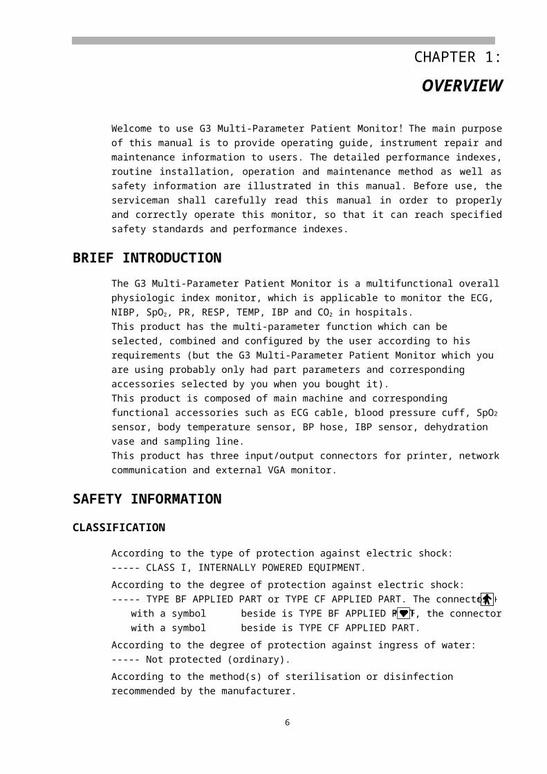
Welcome to use G3 Multi-Parameter Patient Monitor! The main purpose of this manual is to provide operating guide, instrument repair and maintenance information to users. The detailed performance indexes, routine installation, operation and maintenance method as well as safety information are illustrated in this manual. Before use, the serviceman shall carefully read this manual in order to properly and correctly operate this monitor, so that it can reach specified safety standards and performance indexes.
BRIEF INTRODUCTIONThe G3 Multi-Parameter Patient Monitor is a multifunctional overall physiologic index monitor, which is applicable to monitor the ECG, NIBP, SpO2, PR, RESP, TEMP, IBP and CO2 in hospitals.This product has the multi-parameter function which can be selected, combined and configured by the user according to his requirements (but the G3 Multi-Parameter Patient Monitor which you are using probably only had part parameters and corresponding accessories selected by you when you bought it).This product is composed of main machine and corresponding functional accessories such as ECG cable, blood pressure cuff, SpO2 sensor, body temperature sensor, BP hose, IBP sensor, dehydration vase and sampling line.This product has three input/output connectors for printer, network communication and external VGA monitor.
SAFETY INFORMATIONCLASSIFICATION
According to the type of protection against electric shock:----- CLASS I, INTERNALLY POWERED EQUIPMENT.
According to the degree of protection against electric shock: ----- TYPE BF APPLIED PART or TYPE CF APPLIED PART. The connector with a symbol
beside is TYPE BF APPLIED PART, the connector with a symbol beside is TYPE CF APPLIED PART.
According to the degree of protection against ingress of water:----- Not protected (ordinary).
According to the method(s) of sterilisation or disinfection recommended by the manufacturer.----- Equipment with method(s) of sterilisation or disinfection recommended by the manufacturer.
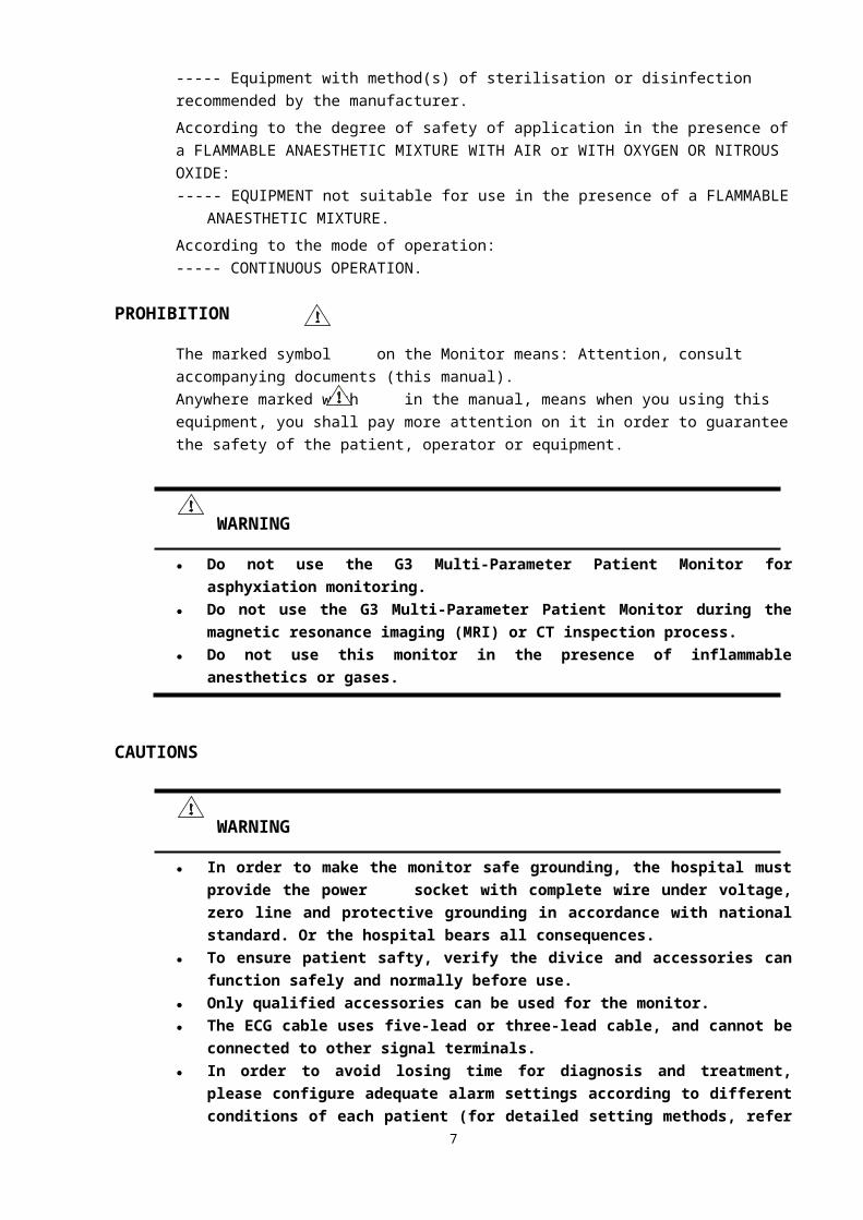
According to the degree of safety of application in the presence of a FLAMMABLE ANAESTHETIC MIXTURE WITH AIR or WITH OXYGEN OR NITROUS OXIDE: ----- EQUIPMENT not suitable for use in the presence of a FLAMMABLE ANAESTHETIC
MIXTURE.
According to the mode of operation:----- CONTINUOUS OPERATION.
6
PROHIBITIONThe marked symbol on the Monitor means: Attention, consult accompanying documents (this manual).Anywhere marked with in the manual, means when you using this equipment, you shall pay more attention on it in order to guarantee the safety of the patient, operator or equipment.
WARNING● Do not use the G3 Multi-Parameter Patient Monitor for asphyxiation monitoring.● Do not use the G3 Multi-Parameter Patient Monitor during the magnetic resonance
imaging (MRI) or CT inspection process.● Do not use this monitor in the presence of inflammable anesthetics or gases.
CAUTIONS
WARNING● In order to make the monitor safe grounding, the hospital must provide the power
socket with complete wire under voltage, zero line and protective grounding in accordance with national standard. Or the hospital bears all consequences.
● To ensure patient safty, verify the divice and accessories can function safely and normally before use.
● Only qualified accessories can be used for the monitor.● The ECG cable uses five-lead or three-lead cable, and cannot be connected to other signal
terminals.● In order to avoid losing time for diagnosis and treatment, please configure adequate
alarm settings according to different conditions of each patient (for detailed setting methods, refer to ALARM SETTINGS in CHAPTER 5).
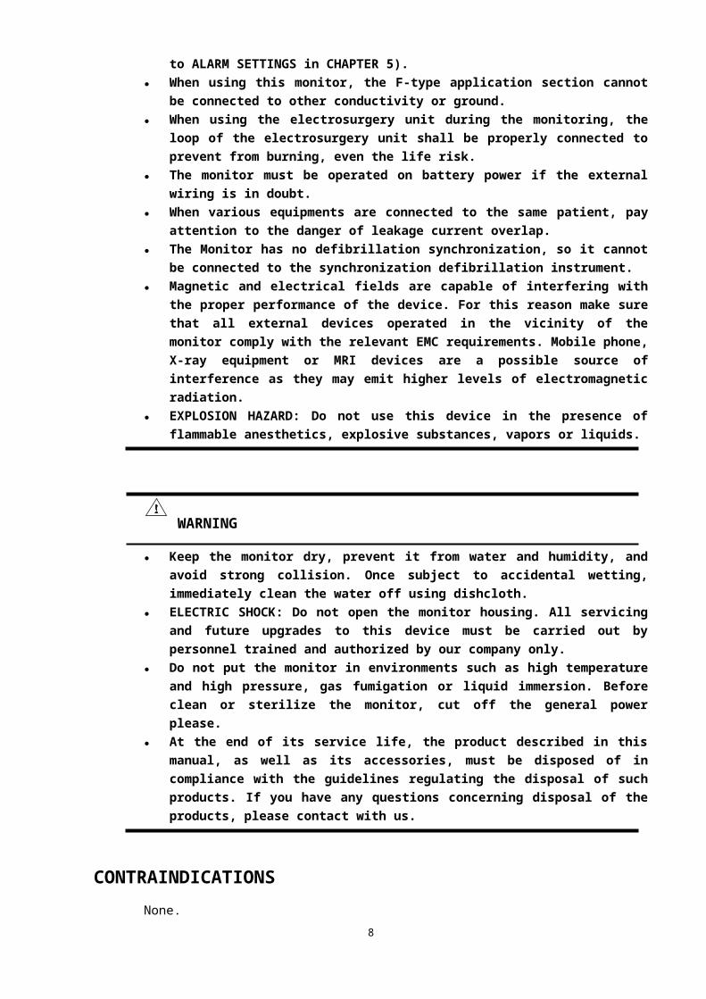
● When using this monitor, the F-type application section cannot be connected to other conductivity or ground.
● When using the electrosurgery unit during the monitoring, the loop of the electrosurgery unit shall be properly connected to prevent from burning, even the life risk.
● The monitor must be operated on battery power if the external wiring is in doubt.● When various equipments are connected to the same patient, pay attention to the danger
of leakage current overlap.● The Monitor has no defibrillation synchronization, so it cannot be connected to the
synchronization defibrillation instrument.● Magnetic and electrical fields are capable of interfering with the proper performance of
the device. For this reason make sure that all external devices operated in the vicinity of the monitor comply with the relevant EMC requirements. Mobile phone, X-ray equipment or MRI devices are a possible source of interference as they may emit higher levels of electromagnetic radiation.
● EXPLOSION HAZARD: Do not use this device in the presence of flammable anesthetics, explosive substances, vapors or liquids.
7
WARNING● Keep the monitor dry, prevent it from water and humidity, and avoid strong collision.
Once subject to accidental wetting, immediately clean the water off using dishcloth.● ELECTRIC SHOCK: Do not open the monitor housing. All servicing and future
upgrades to this device must be carried out by personnel trained and authorized by our company only.
● Do not put the monitor in environments such as high temperature and high pressure, gas fumigation or liquid immersion. Before clean or sterilize the monitor, cut off the general power please.
● At the end of its service life, the product described in this manual, as well as its accessories, must be disposed of in compliance with the guidelines regulating the disposal of such products. If you have any questions concerning disposal of the products, please contact with us.
CONTRAINDICATIONSNone.
FUNCTIONThe G3 Multi-Parameter Patient Monitor can be used to monitor the major parameters such as electrocardiogram (ECG), body temperature (TEMP), impedance respiration (RESP), oxygen saturation (SpO2), invasive blood pressure (IBP), noninvasive blood pressure (NIBP) and CO2
(EtCO2 and FiCO2). It integrates the parameter measurement, display and record export as a whole, which forms a compact and portable monitor. The monitor is capable of monitoring the following parameters:
■ Electrocardiogram (ECG): heart rate (HR), 7 (or 3) leads ECG waveforms and ST segment analysis.
■ Noninvasive blood pressure (NIBP): systolic pressure (SYS), diastolic pressure (DIA) and mean arterial pressure (MAP).
■ Body temperature (TEMP): temperature of channel 1 (T1), temperature of channel 2 (T2) and temperature difference between the two channels (△T).
■ Pulse oxygen saturation (SpO2): SpO2, pulse rate (PR) and SpO2 plethysmogram.■ Respiration: respiration rate (RR) and respiration (impedance respiration or nasal tube
respiration) waveform.■ Invasive blood pressure (IBP): 2 channels of IBP waveforms, systolic pressure (SYS),
diastolic pressure (DIA) and mean pressure (MEAN).■ Carbon dioxide (CO2): end-tidal carbon dioxide (EtCO2), fractional inspiratory carbon
dioxide (FiCO2) and CO2 waveform.
8
CHAPTER 2: INTRODUCTION
EXTERNAL APPEARANCE
G3C
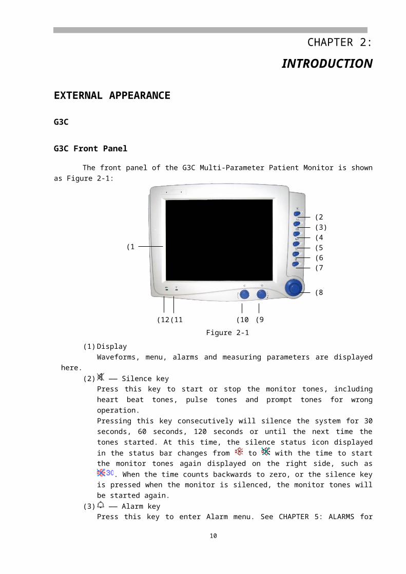
G3C Front PanelThe front panel of the G3C Multi-Parameter Patient Monitor is shown as Figure 2-1:
Figure 2-1
(1) DisplayWaveforms, menu, alarms and measuring parameters are displayed here.
(2) —— Silence keyPress this key to start or stop the monitor tones, including heart beat tones, pulse tones and prompt tones for wrong operation.Pressing this key consecutively will silence the system for 30 seconds, 60 seconds, 120 seconds or until the next time the tones started. At this time, the silence status icon displayed in the
status bar changes from to with the time to start the monitor tones again displayed on the right side, such as . When the time counts backwards to zero, or the silence key is pressed when the monitor is silenced, the monitor tones will be started again.
(3) —— Alarm keyPress this key to enter Alarm menu. See CHAPTER 5: ALARMS for detailed information.
(4) —— Freeze keyThis key is pressed to freeze and unfreeze the waveforms. See CHAPTER 6: WAVEFORM FREEZING AND RECALLING for detailed information.
(5) —— NIBP keyPress this key to start or stop the non-invasive blood pressure measurement. See CHAPTER 15: NIBP MONITORING for detailed information.
9
(2)(3)(4)(5)(6)(7)
(8)
(9)(10)(11)(12)
(1)

(6) —— Print keyPress this key to start or stop the waveforms and measured parameter values printing. See CHAPTER 7: PRINTING for detailed information.
(7) —— Main menu keyPress this key to popup the Main menu or exit the menu currently displayed. See CHAPTER 4: MENU for detailed information.
(8) Rotating mouseTurn the rotating mouse in either direction to highlight labels and menu options. After highlighting the desired selection, press the mouse to execute an operation, make a selection and view a new menu or a dialog box. This procedure is referred to as “select” through out the manual. Remember rotate to highlight, and then press to select.
(9) —— Brightness adjusting knobTurn this knob to adjust the brightness of the monitor screen. Turn clockwise to brighter the screen; turn counterclockwise to darker the screen.
(10) —— Volume adjusting knob
Turn this knob to adjust the volume of the monitor. Turn clockwise to higher the volume; turn counterclockwise to lower the volume.
(11) —— Power indicatorON: The monitor power is turned on.OFF: The monitor power is turned off.
(12) —— Charge indicatorON: AC power is applied to the monitor.OFF: AC power is not applied to the monitor.
G3C Side Panel The side panel of the G3C Multi-Parameter Patient Monitor is shown as Figure 2-2:
Figure 2-2
There are eight connectors on this panel:(1) TEMP1 —— Temperature probe connector (channel 1).(2) TEMP2 —— Temperature probe connector (channel 2).(3) RESP —— Respiration pipe connector.(4) NIBP —— NIBP cuff hose connector.
10
(1) (2)
(3) (4)
(5) (6)
(7) (8)
(5) IBP1 —— IBP transducer connector (channel 1).(6) IBP2 —— IBP transducer connector (channel 2).(7) SpO2 —— SpO2 probe connector.(8) ECG/RESP —— ECG cable connector.
Type CF applied part. The unit displaying this symbol contains an F-type isolated (floating) patient part providing a high degree of protection against shock.
Type BF applied part.
Attention: Consult accompanying documents (this manual).
G3C Rear PanelThe rear panel of the G3C Multi-Parameter Patient Monitor is shown as Figure 2-3:
Figure 2-3
(1) —— Power switch
The key turns on or off the monitor.
(2) Speaker holes
(3) Dispersion holes
(4) AC power input connectorA three-wire power cord can be connected to this receptacle to provide AC power supply to the patient monitor.
(5) Fuse socket
(6) —— Equipotential ground
When the monitor is used with other equipment, it can be connected to equal the potentials.(7) —— Network connector: Standard RJ45 connector.
Through network connector, this monitor can be connected with the central monitoring system, another monitor, or a PC. It enables the functions of other patient viewing, data output and
11
(11)
(1)
(2)
(3)
(7) (8) (9) (10)(5) (6)
(4)
software upgrading.
(8) —— Printer connector
(9) —— VGA monitor connectorA standard colour VGA monitor can be connected to the patient monitor through this connector.
(10) Battery cover
(11) Handle
G3C Mechanics Plan
G3DG3D Front Panel
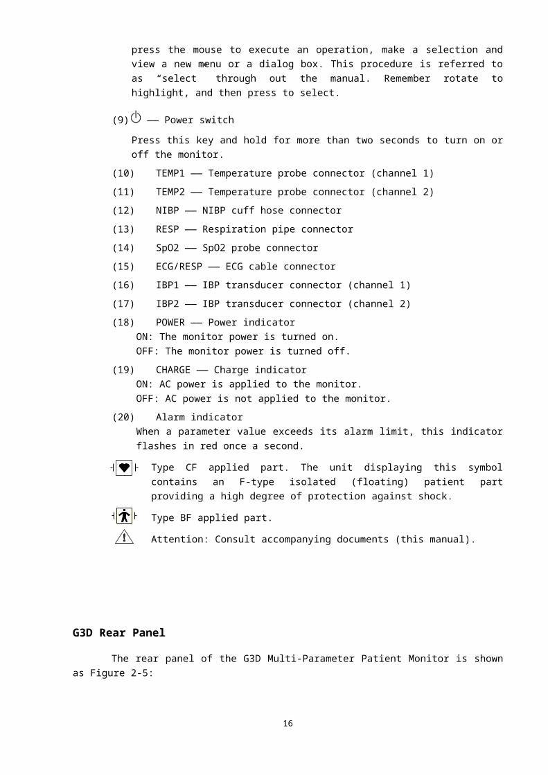
The front panel of the G3D Multi-Parameter Patient Monitor is shown as Figure 2-4:
12
(20)

Figure 2-4
(1) DisplayWaveforms, menu, alarms and measuring parameters are displayed here.
(2) —— Silence key
Press this key to start or stop the monitor tones, including heart beat tones, pulse tones and prompt tones for wrong operation.Pressing this key consecutively will silence the system for 30 seconds, 60 seconds, 120 seconds or until the next time the tones started. At this time, the silence status icon displayed in the
status bar changes from to with the time to start the monitor tones again displayed on the right side, such as . When the time counts backwards to zero, or the silence key is pressed when the monitor is silenced, the monitor tones will be started again.
(3) —— Alarm key
Press this key to enter Alarm menu. See CHAPTER 5: ALARMS for detailed information.
(4) —— Freeze key
This key is pressed to freeze and unfreeze the waveforms. See CHAPTER 6: WAVEFORM FREEZING AND RECALLING for detailed information.
(5) —— NIBP key
Press this key to start or stop the non-invasive blood pressure measurement. See CHAPTER 15: NIBP MONITORING for detailed information.
(6) —— Print key
Press this key to start or stop the waveforms and measured parameter values printing. See CHAPTER 7: PRINTING for detailed information.
(7) —— Main menu key
Press this key to popup the Main menu or exit the menu currently displayed. See CHAPTER 4: 13
(2)(3)(4)(5)(6)(7)
(8)
(9)
(17)(16)(15)(14)(13)(12)(11)(10)
(1)
(18) (19)

MENU for detailed information.
(8) Rotating mouseTurn the rotating mouse in either direction to highlight labels and menu options. After highlighting the desired selection, press the mouse to execute an operation, make a selection and view a new menu or a dialog box. This procedure is referred to as “select” through out the manual. Remember rotate to highlight, and then press to select.
(9) —— Power switch
Press this key and hold for more than two seconds to turn on or off the monitor.
(10) TEMP1 —— Temperature probe connector (channel 1)
(11) TEMP2 —— Temperature probe connector (channel 2)
(12) NIBP —— NIBP cuff hose connector
(13) RESP —— Respiration pipe connector
(14) SpO2 —— SpO2 probe connector
(15) ECG/RESP —— ECG cable connector
(16) IBP1 —— IBP transducer connector (channel 1)
(17) IBP2 —— IBP transducer connector (channel 2)
(18) POWER —— Power indicatorON: The monitor power is turned on.OFF: The monitor power is turned off.
(19) CHARGE —— Charge indicatorON: AC power is applied to the monitor.OFF: AC power is not applied to the monitor.
(20) Alarm indicatorWhen a parameter value exceeds its alarm limit, this indicator flashes in red once a second.
Type CF applied part. The unit displaying this symbol contains an F-type isolated (floating) patient part providing a high degree of protection against shock.
Type BF applied part.
Attention: Consult accompanying documents (this manual).
G3D Rear Panel The rear panel of the G3D Multi-Parameter Patient Monitor is shown as Figure 2-5:
14
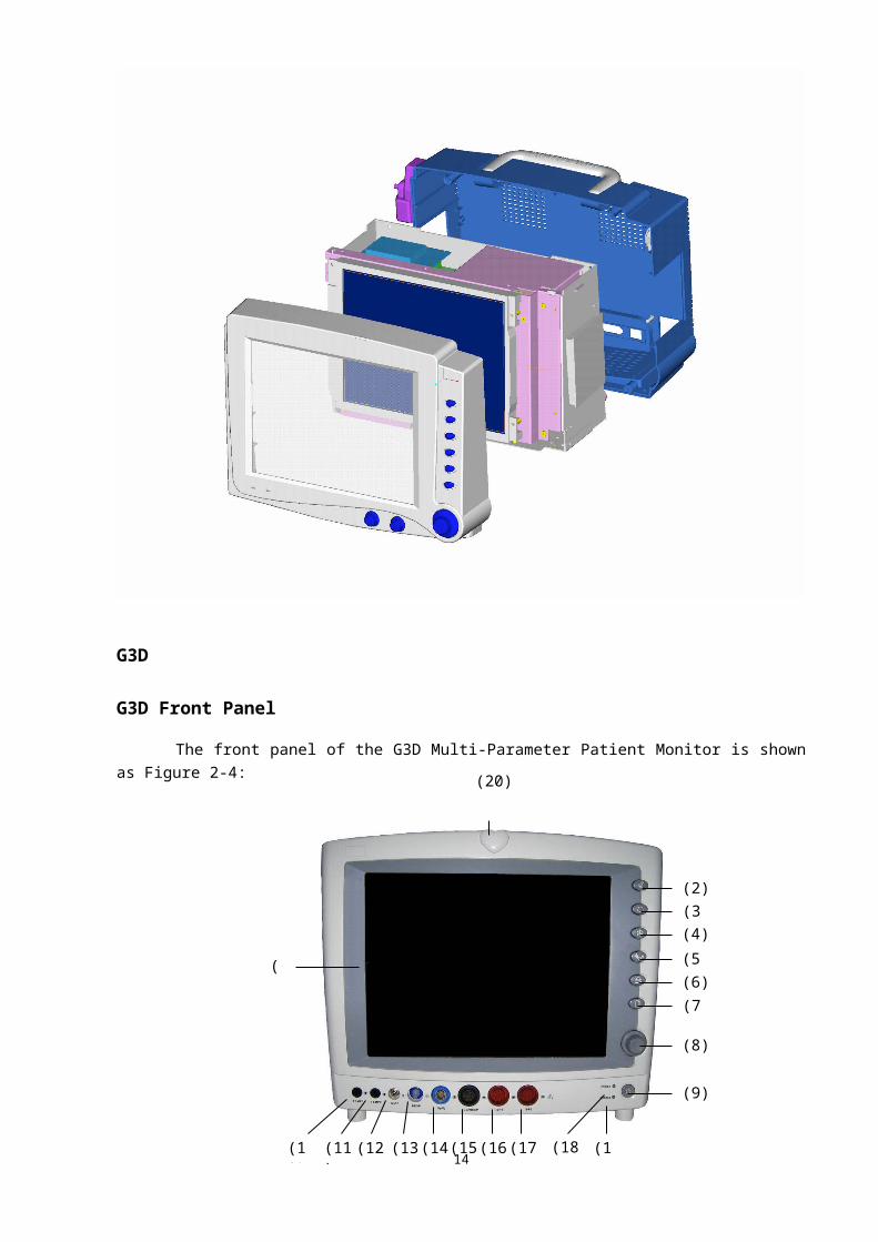
Figure 2-5
(1) Dispersion holes(2) —— Brightness adjusting knob
Turn this knob to adjust the brightness of the monitor screen. Turn clockwise to brighter the screen; turn counterclockwise to darker the screen.
(3) —— Volume adjusting knob
Turn this knob to adjust the volume of the monitor. Turn clockwise to higher the volume; turn counterclockwise to lower the volume.
(4) Fuse socket
(5) —— Equipotential ground
When the monitor is used with other equipment, it can be connected to equal the potentials.(6) —— Network connector: Standard RJ45 connector
Through network connector, this monitor can be connected with the central monitoring system, another monitor, or a PC. It enables the functions of other patient viewing, data output and software upgrading.
(7) Battery cover(8) AC power input connector
A three-wire power cord can be connected to this receptacle to provide AC power supply to the patient monitor.
(9) Handle
15
(1)
(2)
(3)
(4) (5) (6) (7)
(9)
(8)

G3FG3F Front Panel
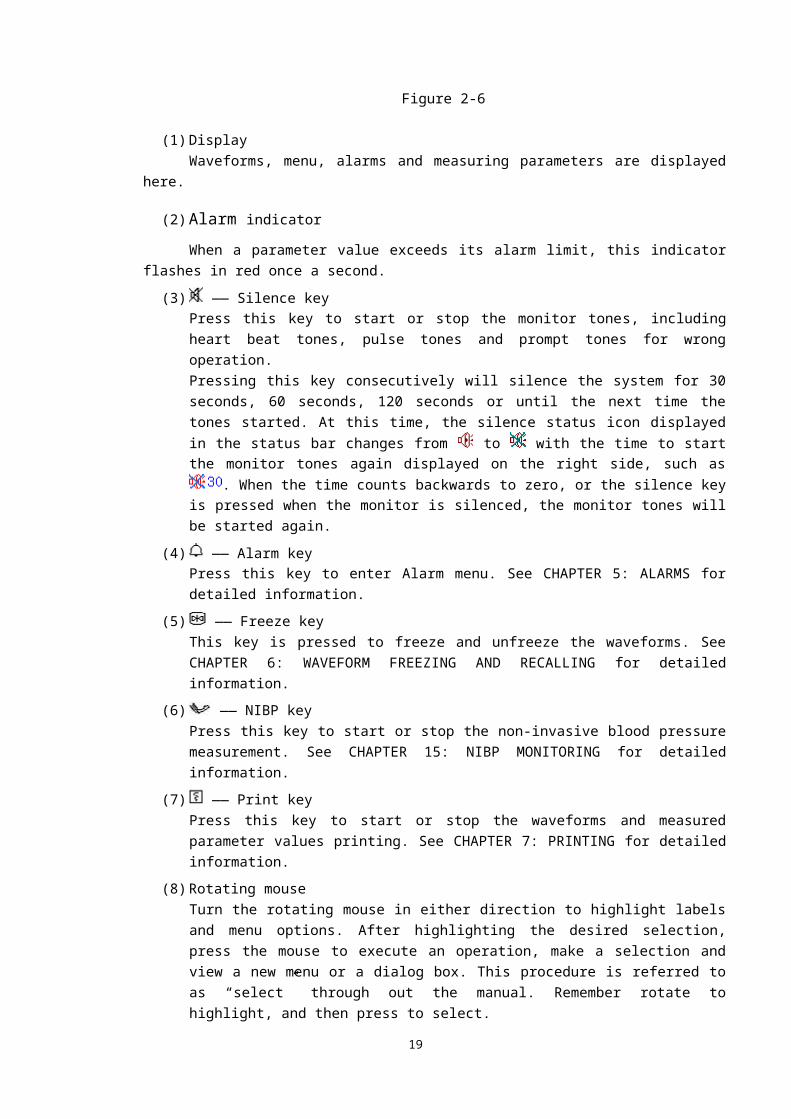
The front panel of the G3F Multi-Parameter Patient Monitor is shown as Figure 2-6:
Figure 2-6
(1) Display
16
(1)
(3)(4)(5)(6)(7)
(8)
(9)
(2)
(11) (10)
Waveforms, menu, alarms and measuring parameters are displayed here.
(2) Alarm indicatorWhen a parameter value exceeds its alarm limit, this indicator flashes in red once a second.
(3) —— Silence keyPress this key to start or stop the monitor tones, including heart beat tones, pulse tones and prompt tones for wrong operation.Pressing this key consecutively will silence the system for 30 seconds, 60 seconds, 120 seconds or until the next time the tones started. At this time, the silence status icon displayed in the
status bar changes from to with the time to start the monitor tones again displayed on the right side, such as . When the time counts backwards to zero, or the silence key is pressed when the monitor is silenced, the monitor tones will be started again.
(4) —— Alarm keyPress this key to enter Alarm menu. See CHAPTER 5: ALARMS for detailed information.
(5) —— Freeze keyThis key is pressed to freeze and unfreeze the waveforms. See CHAPTER 6: WAVEFORM FREEZING AND RECALLING for detailed information.
(6) —— NIBP keyPress this key to start or stop the non-invasive blood pressure measurement. See CHAPTER 15: NIBP MONITORING for detailed information.
(7) —— Print keyPress this key to start or stop the waveforms and measured parameter values printing. See CHAPTER 7: PRINTING for detailed information.
(8) Rotating mouseTurn the rotating mouse in either direction to highlight labels and menu options. After highlighting the desired selection, press the mouse to execute an operation, make a selection and view a new menu or a dialog box. This procedure is referred to as “select” through out the manual. Remember rotate to highlight, and then press to select.
(9) —— Main menu keyPress this key to popup the Main menu or exit the menu currently displayed. See CHAPTER 4: MENU for detailed information.
(10) —— Charge indicatorON: AC power is applied to the monitor.OFF: AC power is not applied to the monitor.
(11) —— Power indicatorON: The monitor power is turned on.OFF: The monitor power is turned off.
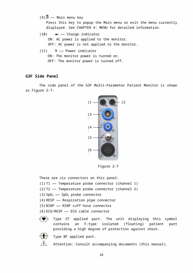
G3F Side PanelThe side panel of the G3F Multi-Parameter Patient Monitor is shown as Figure 2-7:
17

Figure 2-7
There are six connectors on this panel:
(1) T1 —— Temperature probe connector (channel 1)
(2) T2 —— Temperature probe connector (channel 2)
(3) SpO2 —— SpO2 probe connector
(4) RESP —— Respiration pipe connector
(5) NIBP —— NIBP cuff hose connector
(6) ECG/RESP —— ECG cable connector
Type CF applied part. The unit displaying this symbol contains an F-type isolated (floating) patient part providing a high degree of protection against shock.
Type BF applied part.
Attention: Consult accompanying documents (this manual).
G3F Rear PanelThe rear panel of the G3F Multi-Parameter Patient Monitor is shown as Figure 2-8:
18
(1) (2)
(3)
(4)
(5)
(6)
(1)
(2)
(7) (8)
(3)
(5) (6)
(9)(4)
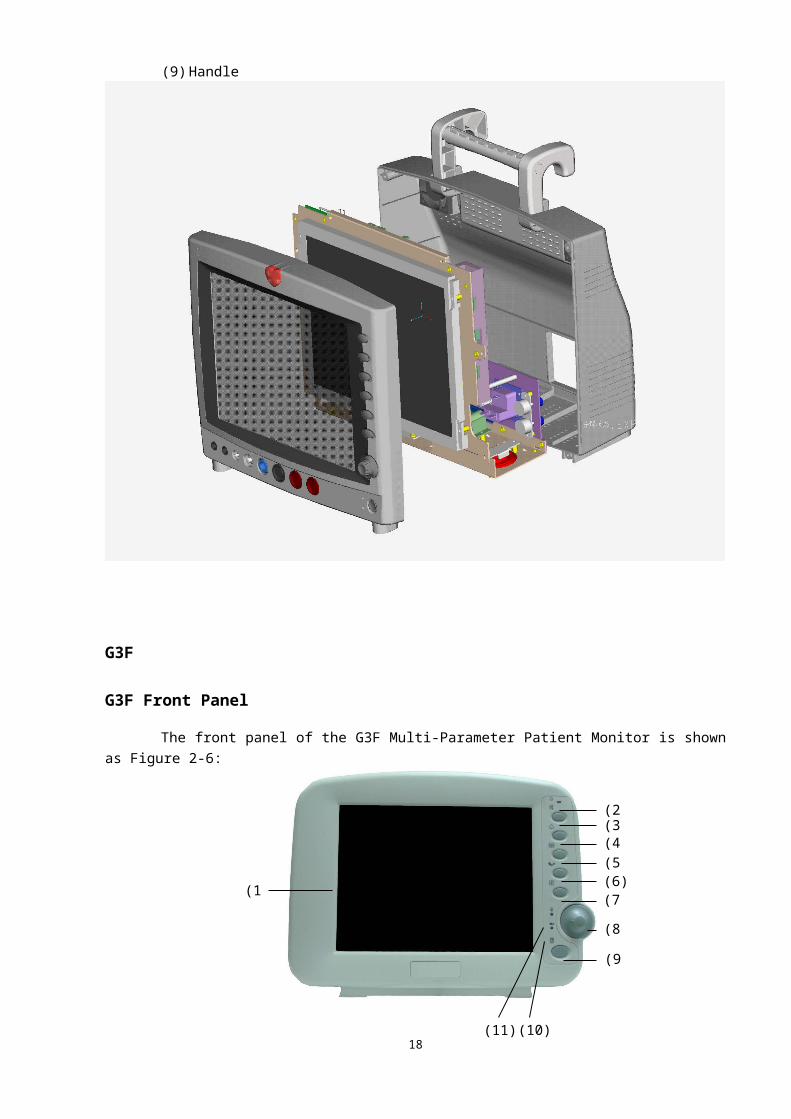
Figure 2-8
(1) Dispersion holes
(2) —— Power switch
The key turns on or off the monitor.(3) AC power input connector
A three-wire power cord can be connected to this receptacle to provide AC power supply to the patient monitor.
(4) Fuse socket
(5) —— Equipotential ground
When the monitor is used with other equipment, it can be connected to equal the potentials.
(6) —— Network connector: Standard RJ45 connectorThrough network connector, this monitor can be connected with the central monitoring system, another monitor, or a PC. It enables the functions of other patient viewing, data output and on-line software upgrading.
(7) —— Brightness adjusting knobTurn this knob to adjust the brightness of the monitor screen. Turn clockwise to brighter the screen; turn counterclockwise to darker the screen.
(8) —— Volume adjusting knob
Turn this knob to adjust the volume of the monitor. Turn clockwise to higher the volume; turn counterclockwise to lower the volume.
(9) Speaker holes
19
G3GG3G Front Panel
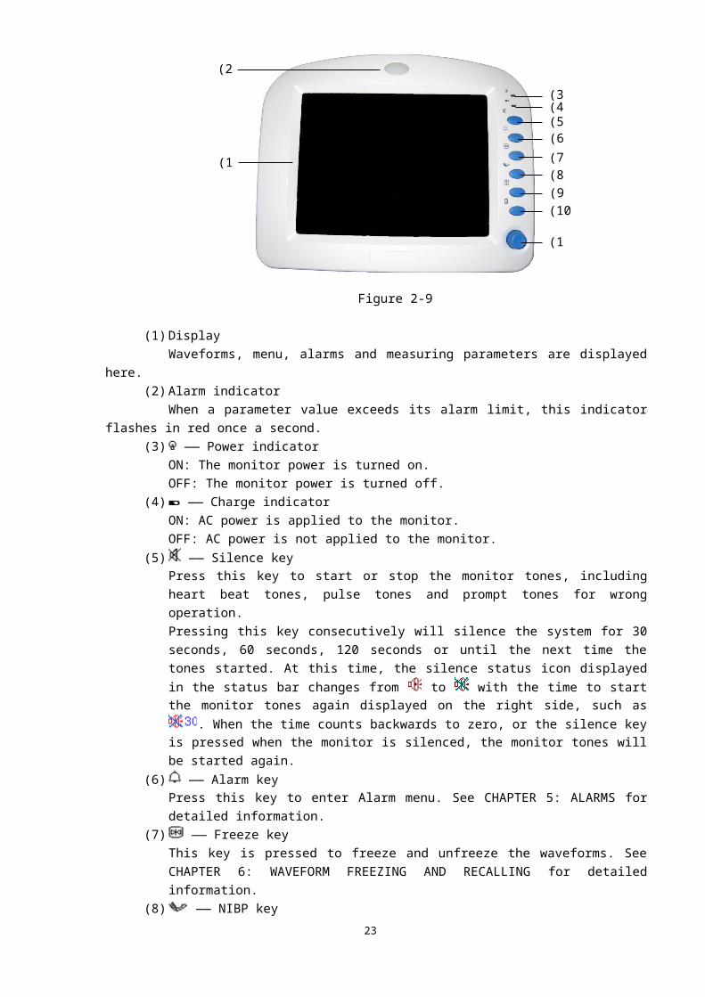
The front panel of the G3G Multi-Parameter Patient Monitor is shown as Figure 2-9:
Figure 2-9
20
(2)
(3)(4)(5)(6)(7)(8)(9)(10)
(1)
(11)
(1) DisplayWaveforms, menu, alarms and measuring parameters are displayed here.
(2) Alarm indicatorWhen a parameter value exceeds its alarm limit, this indicator flashes in red once a second.
(3) —— Power indicatorON: The monitor power is turned on.OFF: The monitor power is turned off.
(4) —— Charge indicatorON: AC power is applied to the monitor.OFF: AC power is not applied to the monitor.
(5) —— Silence keyPress this key to start or stop the monitor tones, including heart beat tones, pulse tones and prompt tones for wrong operation.Pressing this key consecutively will silence the system for 30 seconds, 60 seconds, 120 seconds or until the next time the tones started. At this time, the silence status icon displayed in the
status bar changes from to with the time to start the monitor tones again displayed on the right side, such as . When the time counts backwards to zero, or the silence key is pressed when the monitor is silenced, the monitor tones will be started again.
(6) —— Alarm keyPress this key to enter Alarm menu. See CHAPTER 5: ALARMS for detailed information.
(7) —— Freeze keyThis key is pressed to freeze and unfreeze the waveforms. See CHAPTER 6: WAVEFORM FREEZING AND RECALLING for detailed information.
(8) —— NIBP keyPress this key to start or stop the non-invasive blood pressure measurement. See CHAPTER 15: NIBP MONITORING for detailed information.
(9) —— Print keyPress this key to start or stop the waveforms and measured parameter values printing. See CHAPTER 7: PRINTING for detailed information.
(10) —— Main menu keyPress this key to popup the Main menu or exit the menu currently displayed. See CHAPTER 4: MENU for detailed information.
(11) Rotating mouseTurn the rotating mouse in either direction to highlight labels and menu options. After highlighting the desired selection, press the mouse to execute an operation, make a selection and view a new menu or a dialog box. This procedure is referred to as “select” through out the manual. Remember rotate to highlight, and then press to select.
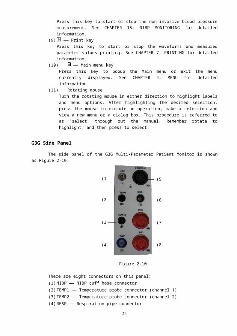
G3G Side Panel The side panel of the G3G Multi-Parameter Patient Monitor is shown as Figure 2-10:
21
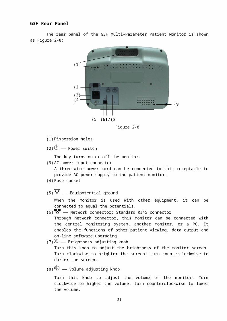
Figure 2-10
There are eight connectors on this panel:
(1) NIBP —— NIBP cuff hose connector
(2) TEMP1 —— Temperature probe connector (channel 1)
(3) TEMP2 —— Temperature probe connector (channel 2)
(4) RESP —— Respiration pipe connector
(5) ECG/RESP —— ECG cable connector
(6) SpO2 —— SpO2 probe connector
(7) IBP1 —— IBP transducer connector (channel 1)
(8) IBP2 —— IBP transducer connector (channel 2)
Type CF applied part. The unit displaying this symbol contains an F-type isolated (floating) patient part providing a high degree of protection against shock.
Type BF applied part.
Attention: Consult accompanying documents (this manual).G3G Rear Panel
The rear panel of the G3G Multi-Parameter Patient Monitor is shown as Figure 2-11:
22
(1)
(2)
(3)
(4)
(5)
(6)
(7)
(8)
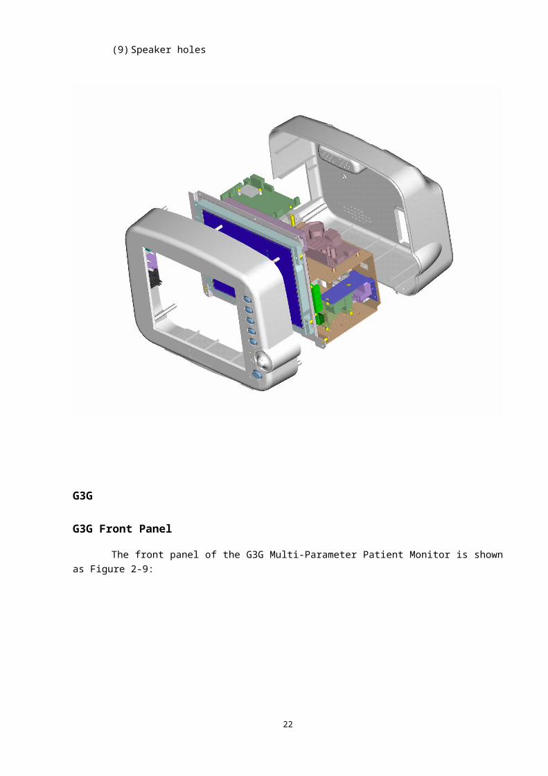
Figure 2-11
(1) Dispersion holes
(2) —— Power switch
The key turns on or off the monitor.
(3) —— Equipotential ground
When the monitor is used with other equipment, it can be connected to equal the potentials.
(4) —— Printer connector
(5) —— VGA monitor connectorA standard colour VGA monitor can be connected to the patient monitor through this connector.
(6) —— Network connector: Standard RJ45 connectorThrough network connector, this monitor can be connected with the central monitoring system, another monitor, or a PC. It enables the functions of other patient viewing, data output and software upgrading.
(7) —— Brightness adjusting knobTurn this knob to adjust the brightness of the monitor screen. Turn clockwise to brighter the screen; turn counterclockwise to darker the screen.
(8) —— Volume adjusting knob
Turn this knob to adjust the volume of the monitor. Turn clockwise to higher the volume; turn counterclockwise to lower the volume.
(9) AC power input connectorA three-wire power cord can be connected to this receptacle to provide AC power supply to the patient monitor.
(10) Fuze socket(11) Speaker holes
23
(1)
(3) (4) (5) (6) (7) (8)
(9)
(2) (10)
(11)
(12)
(12) Handle
G3H Part
FRONT PANELThe front panel of the G3H Multi-Parameter Patient Monitor is shown as Figure 2-1:
Figure 2-1
(13) Alarm IndicatorWhen a parameter value exceeds its alarm limit, this indicator flashes in red once a second.
(14) DisplayWaveforms, menu, alarms and measuring parameters are displayed here.
(15) —— Silence key
Press this key to start or stop the monitor tones, including heart beat tones, pulse tones and 24
(2)
(3) (4) (5) (7) (9) (10) (11)(6) (8)
(1)
prompt tones for wrong operation.Pressing this key consecutively will silence the system for 30 seconds, 60 seconds, 120 seconds or until the next time the tones started. At this time, the silence status icon displayed in the
status bar changes from to with the time to start the monitor tones again displayed on the right side, such as . When the time counts backwards to zero, or the silence key is pressed when the monitor is silenced, the monitor tones will be started again.
(16) —— Alarm key
Press this key to enter Alarm menu. See CHAPTER 5: ALARMS for detailed information.
(17) —— Freeze key
This key is pressed to freeze and unfreeze the waveforms. See CHAPTER 6: WAVEFORM FREEZING AND RECALLING for detailed information.
(18) —— Charge indicatorON: AC power is applied to the monitor.OFF: AC power is not applied to the monitor.
(19) Rotating mouseTurn the rotating mouse in either direction to highlight labels and menu options. After highlighting the desired selection, press the mouse to execute an operation, make a selection and view a new menu or a dialog box. This procedure is referred to as “select” through out the manual. Remember rotate to highlight, and then press to select.
(20) —— Power indicatorON: The monitor power is turned on.OFF: The monitor power is turned off.
(21) —— NIBP key
Press this key to start or stop the non-invasive blood pressure measurement. See CHAPTER 15: NIBP MONITORING for detailed information.
(22) —— Print key
Press this key to start or stop the waveforms and measured parameter values printing. See CHAPTER 7: PRINTING for detailed information.
(23) —— Main menu key
Press this key to popup the Main menu or exit the menu currently displayed. See CHAPTER 4: MENU for detailed information.
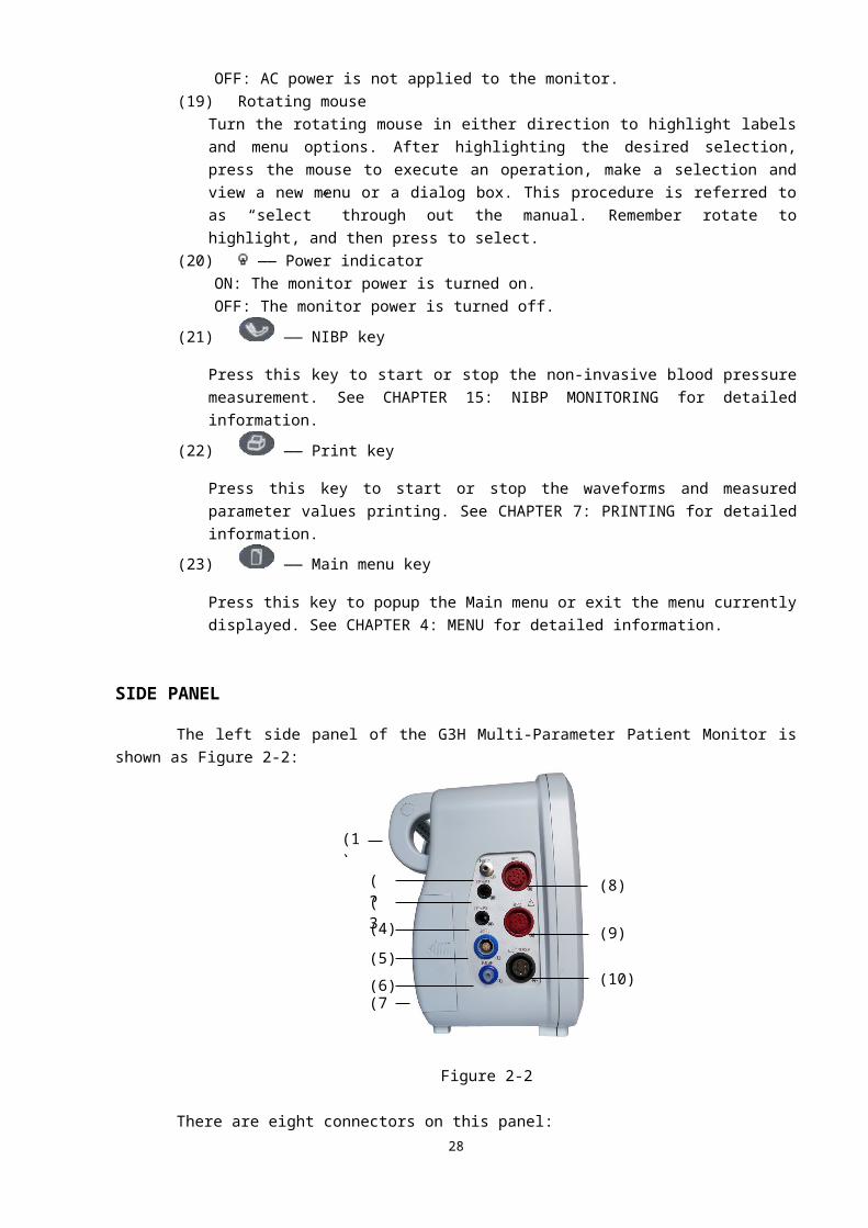
SIDE PANELThe left side panel of the G3H Multi-Parameter Patient Monitor is shown as Figure 2-2:
25

Figure 2-2
There are eight connectors on this panel:(1) Handle.(2) NIBP —— NIBP cuff hose connector.(3) TEMP1 —— Temperature probe connector (channel 1).(4) TEMP2 —— Temperature probe connector (channel 2).(5) SpO2 —— SpO2 probe connector.(6) RESP —— Respiration pipe connector.(7) Battery cover.(8) IBP1 —— IBP transducer connector (channel 1).(9) IBP2 —— IBP transducer connector (channel 2).(10)ECG/RESP —— ECG cable connector.
Type CF applied part. The unit displaying this symbol contains an F-type isolated (floating) patient part providing a high degree of protection against shock.
Type BF applied part.
Attention: Consult accompanying documents (this manual).
The right side panel of the G3H Multi-Parameter Patient Monitor is shown as Figure 2-3:
26
(1)
(2)(3)
(4)
(5)
(6)(7)
(8)
(9)
(10)
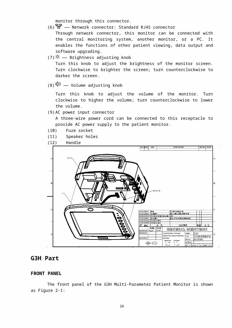
Figure 2-3
There are eight connectors on this panel:(9) Printer.(10) AC power input connector
A three-wire power cord can be connected to this receptacle to provide AC power supply to the patient monitor.
(11) Fuse socket
(12) —— Equipotential ground
When the monitor is used with other equipment, it can be connected to equal the potentials.(13) —— VGA monitor connector
A standard colour VGA monitor can be connected to the patient monitor through this connector.(14) —— Network connector: Standard RJ45 connector.
Through network connector, this monitor can be connected with the central monitoring system, another monitor, or a PC. It enables the functions of other patient viewing, data output and software upgrading.
(15) Handle.
REAR PANELThe rear panel of the G3H Multi-Parameter Patient Monitor is shown as Figure 2-4:
27
(1)
(3) (4) (5)
(6)
(7)
(2)
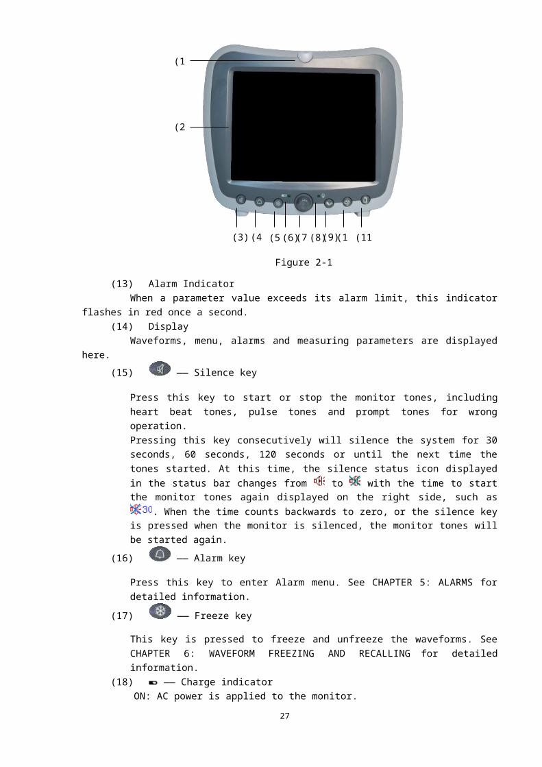
Figure 2-4
(12) Handle.(13) Battery cover.
(14) —— Power switch.
Mechanics Plan
28
(1) (3)
(2)
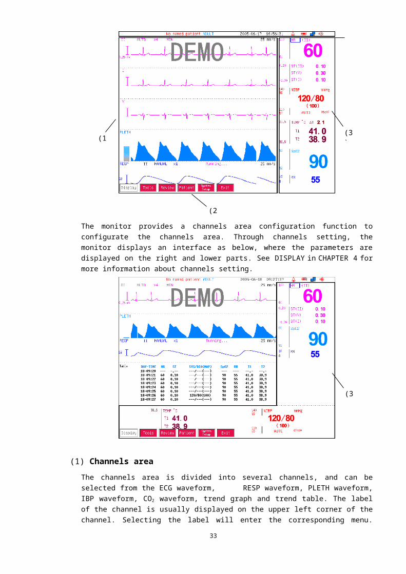
DISPLAYThe display of this monitor is divided into four major areas, such as channels area, parameters area, status bar and menu bar. The status bar is on the top part of the screen, the channels area is under the status bar, on the left part of the screen, while the menu bar is at the lower part of the screen. The parameters are always displayed on the right part of the screen. The menu pops up and shuts out part of the channels area and parameters area. The standard display interface is as the following:
29
(4)

The monitor provides a channels area configuration function to configurate the channels area. Through channels setting, the monitor displays an interface as below, where the parameters are displayed on the right and lower parts. See DISPLAY in CHAPTER 4 for more information about channels setting.
(1) Channels areaThe channels area is divided into several channels, and can be selected from the ECG waveform, RESP waveform, PLETH waveform, IBP waveform, CO2 waveform, trend graph and trend table. The label of the channel is usually displayed on the upper left corner of the channel. Selecting the label will enter the corresponding menu. What is displayed at the same row of the label is the status information concerning this channel.
(2) Menu barThe menu bar automatically pops up and disappears. Pressing the Main menu key, Alarm key, Freeze
30
(1)
(2)
(3)
(3)

key or the parameter/channel labels can activate the corresponding menu to display.
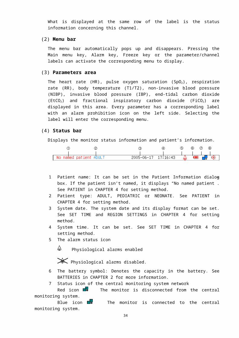
(3) Parameters areaThe heart rate (HR), pulse oxygen saturation (SpO2), respiration rate (RR), body temperature (T1/T2), non-invasive blood pressure (NIBP), invasive blood pressure (IBP), end-tidal carbon dioxide (EtCO2) and fractional inspiratory carbon dioxide (FiCO2) are displayed in this area. Every parameter has a corresponding label with an alarm prohibition icon on the left side. Selecting the label will enter the corresponding menu.
(4) Status barDisplays the monitor status information and patient’s information.
① Patient name: It can be set in the Patient Information dialog box. If the patient isn’t named, it displays “No named patient”. See PATIENT in CHAPTER 4 for setting method.
② Patient type: ADULT, PEDIATRIC or NEONATE. See PATIENT in CHAPTER 4 for setting method.
③ System date. The system date and its display format can be set. See SET TIME and REGION SETTINGS in CHAPTER 4 for setting method.
④ System time. It can be set. See SET TIME in CHAPTER 4 for setting method.⑤ The alarm status icon
Physiological alarms enabled
Physiological alarms disabled.
⑥ The battery symbol: Denotes the capacity in the battery. See BATTERIES in CHAPTER 2 for more information.
⑦ Status icon of the central monitoring system networkRed icon The monitor is disconnected from the central monitoring system.Blue icon The monitor is connected to the central monitoring system.
⑧ The silence status icon System not silenced
System silenced.
WARNING
● The system doesn’t generate physiological alarms if the icon shows.
BATTERIESThis monitor designed to operate on baterry power during intra-hosipital patient transfer or whenever the power supply is interrupted. The battery is charged automatically when the monitor is connected to AC power, no matter the monitor is powered on or not.The battery symbol displayed on the main screen tells the status of the battery.
31
① ② ③ ④ ⑤ ⑥ ⑦ ⑧

■ ( or ) The battery is installed in the battery slot.The grid part indicates its capacity.
■ (red and flashing) No battery is installed in the battery slot or the electrical volume is to be exhausted.
Besides, the charge indicator also indicates the status of the battery.■ ON The battery is being charged or the battery is fully
charged.■ OFF No battery is installed or the battery is installed but the monitor is not connected
to AC power.The capacity of the battery is limited. When the battery capacity is too low, a flashing red symbol
shows in the status bar. At this moment, the AC power shall be applied to the monitor.
NOTE● Take out the battery before the monitor is transported or will not be used for a long time.
WARNING● Keep the battery out of the reach of children.● Only use the battery specified by the manufacturer.
BATTERY MAINTENANCE
Conditioning a BatteryA battery should be conditioned before it is used for the first time. A battery conditioning cycle is one uninterrupted discharge of the battery. Batteries should be conditioned regularly to maintain their useful life. Condition a battery once when it is used or stored for two months, or when its run time becomes noticeably shorter.To condition a battery, follow this procedure:1. Disconnect the monitor from the patient and stop all monitoring or measuring.2. Insert the battery in need of conditioning in the battery slot of the monitor.3. Apply AC power to the monitor and allow the battery to charge uninterrupted for 10 hours.4. Remove AC power and allow the monitor to run from the battery until it shuts off.5. Apply AC power again to the monitor and allow the battery to charge uninterrupted for 10
hours.6. This battery is now conditioned and the monitor can be returned to work.
Checking a BatteryThe performance of a rechargeable battery may deteriorate over time. To check the performance of a battery, follow this procedure:1. Disconnect the monitor from the patient and stop all monitoring or measuring.2. Apply AC power to the monitor and allow the battery to charge
uninterrupted for 10 hours.
32

3. Remove AC power and allow the monitor to run from the battery until it shuts off.
4. The operating time of battery reflects its performance directly.Please replace the battery or contact with the maintenance personnel if its operating time is significantly lower than the specified time.
NOTE● Life expectancy of a battery depends on how frequent and how long it is used. For a
properly maintained and stored lead-acid or lithium ion battery, its life expectancy is about 2 or 3 years respectively. For more aggressive use models, life expectancy can be less. We recommend replacing lead acid batteries every 2 years and lithium ion batteries every 3 years.
● The battery might be damaged or malfunctioned if its operating time is too short after being fully charged. The operating time depends on the configuration and operation. For example, measuring NIBP more frequently will also shorten the operating time.
BATTERY RECYCLINGWhen a battery has visual signs of damage, or no longer holds a charge, it should be replaced. Remove the old battery from the monitor and recycle it properly. To dispose of the batteries, follow local laws for proper disposal.
WARNING● Do not disassemble batteries, or dispose of them in fire, or cause them to short circuit.
They may ignite, explode, leak or heat up, causing personal injury.
33
CHAPTER 3: INSTALLATION
WARNING● The installation of the monitor must be carried out by personnel authorized by us. The
software copyright of the monitor is solely owned by our company. Any action to change, copy or exchange the software copyright by any organization or person is regarded as copyright infringement and is not allowed.
● If the monitor is connected to another electrical instrument and the instrument specifications cannot tell whether the instrument combination is hazardous (e.g. due to summation of leakage currents), you should consult us or experts in the field to ensure the required safety of all instruments concerned.
NOTE● The operations in this section are not all required. User-customized installation by
authorized personnel is provided.
UNPACKING AND CHECKINGPlease open the package according to the positions marked on the packing case, and take out the monitor and accessories carefully. Check the accessories against the packing list. Check the monitor and accessories for any mechanical damage.Contact the distributor immediately in case of any problem.Friendly remind: Please save the packing case and packaging material for further transport and storage.
WARNING● Be sure to keep the packaging materials from children’s reach.● Disposal of the packaging materials shall comply with your local requirements.● The equipment might be contaminated in storage, transport or when used. Verify the
package and the single use accessories are intact. In case of any damage, do not apply it to patients.
34
ENVIRONMENTAL REQUIREMENTSThe operating environment of the monitor must meet the requirements specified in ENVIRONMENTAL SPECIFICATIONS in APPENDIX A.The environment where this monitor is to be used should be free from noise, vibration, dust, and corrosive or explosive and inflammable substances. Do not place the monitor against the wall, and do not plug up the dispersion holes on the back and two sides of the monitor for proper air circulation.Condensation can form when the monitor is moved from one location to another, and being exposed to differences in humidity or temperature. Make sure that during operation the instrument is free from condensation.
INSTALLATION METHOD
CONNECTING TO AC POWER SUPPLY1. Use the original three-wire AC power cord.2. Connect the power cord to the receptacle for AC power cord on the rear
panel of the monitor.3. Connect the other end of the power cord to a compatible 3-prong hospital
grade AC power outlet.The 3-prong power outlet must be grounded. If it is doubted, contact related personnel of the hospital.
WARNING● Confirm the AC power supply is in conformity with the requirements of this equipment:
(100~240)V a.c., 50/60Hz.● Do not use three-wire to two-wire adapter with this instrument.● To avoid unexpected power interruption, do no use power outlet with a wall-mounted
switch control.
INSTALLING THE BATTERYIf the monitor is to be powered by the internal battery, install the battery following the steps as below:1. Slide the battery door in the indicated direction (G3C/G3D), or screw off
the screws and open the rear panel.2. Insert the battery into the battery slot per the “+” and “-” indications.3. Fix the battery with screws (for G3D, cover it with the plate first).4. Close the battery door (G3C/G3D), or fix the rear panel with screws
(G3F/G3G).
WARNING
35

● Make sure the monitor has been disconnected with AC power supply before battery installation.
● Make sure the battery door or the rear panel is securely latched. Falling batteries could seriously or fatally injure a patient.
EQUIPOTENTIAL GROUNDINGWhen other equipments are used together with the monitor, the grounding cable should be used to connect the equipotential ground of the monitor and of other equipments. This helps to reduce the potential differences between different pieces of equipment, and ensure the safety of the operator and patient.
WARNING● If the grounding system is in doubt, the monitor must be supplied from its internal
battery.● Accessory equipments connected to this patient monitor must be certified according to the
respective IEC standards (e.g. IEC 60950 for information technology equipment and IEC 60601-1 for medical electrical equipment). Furthermore all configurations shall comply with the valid version of the system standard IEC 60601-1-1. Any person who connects additional equipment to the signal input or signal output is responsible to ensure the system complies with the requirements of the valid version of the system standard IEC 60601-1-1. If in doubt, contact our company or customer service.
CONNECTING PATIENT SENSORS AND PROBESConnect the necessary patient sensors or probes to the monitor. For details, see the chapters for specific parameter monitoring in the following pages, or corresponding instructions for sensors and probes.
CONNECTING THE NETWORK CABLEThe network connector of the monitor is a standard RJ45 connector. It connects the monitor with the central monitoring system, or with a PC for upgrading or data output. It can also connect with another patient monitor for other patient viewing.1. Connect one end of the network cable with the network connector of the monitor.2. Connect the other end of the network cable with the hub or switch of the central monitoring
system, or with the network connector of a PC, or with the network connector of another patient monitor.
WARNING● Different network cable may be used for different connections. Please consult our
customer service personnel for details.● The system upgrading through the network connector is to be executed by our authorized
36

personnel only.
CONNECTING TO VGA MONITORThis monitor can be connected with a standard color VGA monitor. The VGA monitor will display the patient waveforms and parameters measured by the patient monitor. To connect the patient monitor with the VGA monitor, follow the steps as below.1. Install the VGA monitor at a distance of more than 1.5 meters from the patient.2. Power off the patient monitor.3. Connect the signal cable of the VGA monitor to the VGA connector on the rear panel of the
patient monitor.4. Power on the VGA monitor and then the patient monitor.
REPLACE THE FUSE 1. Pull out the fuse socket (G3C/G3D/G3F), or screw off the fuse socket (G3G).2. Push up the fuse and replace it with a new one.3. Push the fuse socket back (G3C/G3D/G3F), or screw back the fuse socket (G3G).
POWERING ON THE MONITORAfter installing the monitor, please follow the procedures described below to power on the monitor:1. Before using the monitor, please carry out corresponding safety inspection
as given in INSPECTION in CHAPTER 20.2. Press the Power switch and the Power indicator is lighted on.3. The boot-strap picture and pace-bar are displayed on the screen.4. When the pace-bar reaches 100%, the system displays the main screen.5. At this time, you can operate the monitor using the keys and rotating
mouse.
POWERING OFF THE MONITOR
To power off the monitor, please follow the procedures below:1. Confirm the patient monitoring is to be finished.2. Disconnect the cables and sensors between the monitor and the patient.3. Press the Power switch, and the monitor will be powered off.
37

CHAPTER 4: MENU
MENU OPERATIONThe basic format of menu is as the following (Main menu):
POPUP MENUThe monitor has four methods to popup the menu:■ Press the Main menu key on the front panel to popup the Main menu.■ Press the Alarm key on the front panel to popup the Alarm menu.■ Press the Freeze key on the front panel to popup the Freeze menu.■ Select a parameter/channel label to popup the corresponding menu.
BROWSE MENUThe inverse black button in the menu bar is the button selected by the cursor. Select the desired button to popup the corresponding submenu or dialog, or carry out the selected function. Please refer to the relevant part in this manual for detailed information.
EXIT MENUThe monitor has three methods to exit from the menu:■ Select the “Exit” button in the right-end of menu bar to return to the previous menu.■ When a menu is displayed, press the Main menu key on the front panel to exit the menu.■ No operation for more than one minute, the monitor automatically exits the menu.
DISPLAYPressing the Main menu key on the front panel pops up the following Main menu:
■ Display: Sets the display interface.■ Tools: Sets the practical tools.
38
■ Review: Checks/reviews the history trend or data.■ Patient: Sets the patient’s information.■ System Setup: Sets the system information.■ Recorder Setup: Sets the recorder/ built-in printer parameters.
Selecting Display in the Main menu pops up the following Display menu.
FIXED FORMATSelecting Fixed Format in the Display menu pops up the following menu.
In this Fixed Format menu, the user can select display format from five existed formats. Select a button, the main interface will display accordingly. 1 ECG: One ECG (main lead) waveform is displayed in the channels area.
2 ECGs: Two ECG (main lead and another lead) waveforms are displayed in the channels area.
3 ECGs: Three ECG wavforms, a PLETH wavform and a RESP waveform are displayed in the channels area. It is the default display fomat.
39
7 ECGs: Seven ECG (II、I、III、aVR、aVL、aVF and V leads) waveforms are displayed in the channels area.
Huge Digit: HR and SpO2 are displayed in huge digit, while the main lead ECG waveform is displayed on the top part of the screen.
USER FORMATSelecting User Format in the Display menu pops up the following menu.
In this User Format menu, the display format of main interface can be set as the user format. The system supports 5 user formats. The current display format can be saved as a user format via Format Setup button. See the following FORMAT SETUP for detailed information.
40
FORMAT SETUPSelecting Format Setup in the Display menu pops up the following dialog box.
The Setup Display Channel dialog box displays the label of channel that is displayed in the channels area currently.Save as: “Not Save” or “User Format 1~5” could be selected. If “Not Save” is selected, the channels area displays the channels selected in this dialog box. If “User Format 1~5” is selected, not only the channels area displays the channels selected in this dialog box, the current display format will be saved as a user format also.Select a desired channel, the Select Channel menu as figure above pops up. All channels are listed in this menu. Select the desired channel label to add it into the Setup Display Channel dialog box.
NOTE● Cannot display the same channel.● If channel is “Blank”, it means no channel to be displayed at this position.● If select the ECG channel, the system will match the relevant ECG lead automatically.
OXYCRGSelect oxyCRG in the Display menu, the following oxyCRG graph will be displayed in the channels area.
The oxyCRG is formed by HR, SpO2 and RESP trend graphs. On the right side of the RESP label, its relevant information is displayed, and at the bottom of the RESP trend graph, the time scale is displayed, such as 1min, 2min, 3min or 4min. OxyCRG only shows the trend graph for the last 3 or 4 minutes.
41
ALARM LIMITSelect Alarm Limit in the Display menu to display or hide the alarm limit in parameters area, shown as below.
WAVEFORM SPEEDSelect Waveform Speed in the Display menu, the following Waveform Speed Setting dialog box pops up, where the waveform speed of the ECG/PLETH/IBP and RESP/CO2 can be adjusted.
Options: 6.25mm/s, 12.5mm/s, 25mm/s and 50mm/s. The default waveform speed is 25mm/s.
OTHER SETTINGSSelecting Other Settings in the Display menu pops up the following menu:
NIBP SizeSelect NIBP Size in the Other Settings menu, the NIBP value display format switches among three formats, shown as below.
IBP1 SizeSelect IBP1 Size in the Other Settings menu, the display format of channel 1 IBP value switches among three formats, shown as below.
IBP2 SizeSelect IBP2 Size in the Other Settings menu, the display format of channel 2 IBP value switches among three formats, shown as below.
42
or or
or or
Alarm limit
IBP OverlapSelect IBP Overlap in the Other Settings menu, the IBP waveforms of two channels are displayed in a channel, shown as below.
Menu FontSelect Menu Font in the Other Settings menu, the menu font switches between large font and small font, shown as below.
Screen FontSelect Screen Font in the Other Settings menu, the screen font switches between large font and small font, shown as below.
Pleth FillSelect Pleth Fill in the Other Settings menu, the PLETH waveform will be filled or be blank, shown as below.
CO2 FillSelect CO2 Fill in the Other Settings menu, the CO2 waveform will be filled or be blank, shown as below.
TOOLSSelecting Tools in the Main menu pops up the following menu:
■ Event: Sets the event. See CHAPTER 9: EVENTS for detailed information.
43
or or

■ Drug Calculator: Calls the drug calculator. See CHAPTER 10: DRUG CALCULATOR for detailed information.
■ Other Patient: Views waveforms and parameter values of another monitor in the same LAN. See CHAPTER 11: OTHER PATIENT VIEWING for detailed information.
■ Standby: Enters standby mode. In this mode, the monitor shows standby interface instead of the main interface and gives the audible alarms if an alarm occurs. Press the Main menu key on the front panel to return to the normal mode.
REVIEWSelecting Review in the Main menu pops up the following menu.
■ Trend: Reviews/checks the trend data. See CHAPTER 8: TRENDS for detailed information.■ Recall: Recalls the saved waveform. See CHAPTER 6: WAVEFORM FREEZING AND
RECALLING for detailed information.
PATIENTSelect Patient in the Main menu, and the following Patient information dialog box pops up.
■ No: Patient identification number, set via soft keyboard.■ Name: Patient name, set via soft keyboard. If no name is set, it shows “No named patient”.■ Sex: Patient gender. Male or Female, while Male is the default.■ Age: Patient age. The default age is 25. Rotating the mouse clockwise increases the age, while
counterclockwise decreases the age.■ Patient type: ADULT, PEDIATRIC or NEONATE, while ADULT is the default.
Soft Keyboard
Select the input field on the right side of No as the figure above, the soft keyboard pops up, shown as below.
Consecutively select this button, the Characters field shows the capital, lowercase,
numeral and punctuation in sequence.
Pages down or pages up the characters in the Characters field.
Characters field: Press and turn the rotating mouse to select the desired character,
then press the mouse again to add it into the input field.
44
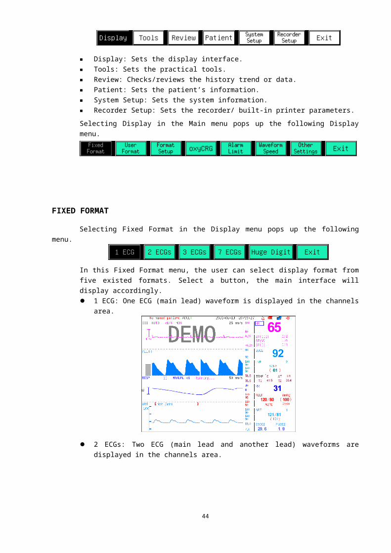
Moves the cursor in the Characters field. Select this button then turn the rotating mouse
to move the cursor forward or backward.
Deletes the character before the cursor.
Confirms the input.
SYSTEM SETUPSeleting System Setup in the Main menu pops up the following menu.
In this menu, Calibration is used by the manufacturer, while the others are used by the user.
SET TIMESelecting Set Time in the System Setup menu pops up the Set Date dialog box, shown as below.
The Year, Month, Day, Hour, Minute and Second of the system time can be set in this dialog box.
NOTE● Reseting the system time will clear the stored trend data.
REGION SETTINGSSelecting Region Settings in the System Setup menu pops up the following menu.
Select UnitsSelecting Select Units in the Region Settings menu pops up the Parameter Unit dialog box, shown as below.
The pressure unit and temperature unit can be set in this dialog box. The options of pressure unit: kPa and mmHg. The options of temperature unit: Cent and Frnt. Click Ok to confirm the selection, and the corresponding value will be displayed with the selected unit.
45
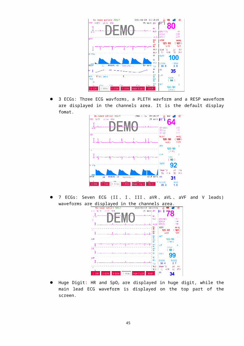
Date FormatSelecting Date Format in the Region Settings menu pops up the Set Date Format dialog box to set the date format, shown as below.
Power FrequencySelecting Power Frequency in the Region Settings menu pops up the Set Power Frequency dialog box, shown as below.
The power frequency can be set as 50Hz or 60Hz.
NOTE● Please set the proper power frequency, or the ECG signal noise will be loud.
LanguageSelect Laguage in the Region Settings menu, and the system language changes.
NETWORK SETTINGSSelecting Network Settings in the System Setup menu pops up the following menu.
IP AddressSelecting IP Address in the Network Settings menu pops up the Network setting dialog box to set the IP address, shown as below.
If “Use dynamic IP configuration (DHCP)” is selected, the monitor is distributed an IP address automatically when it is turned on to prevent from the IP address conflict.
46
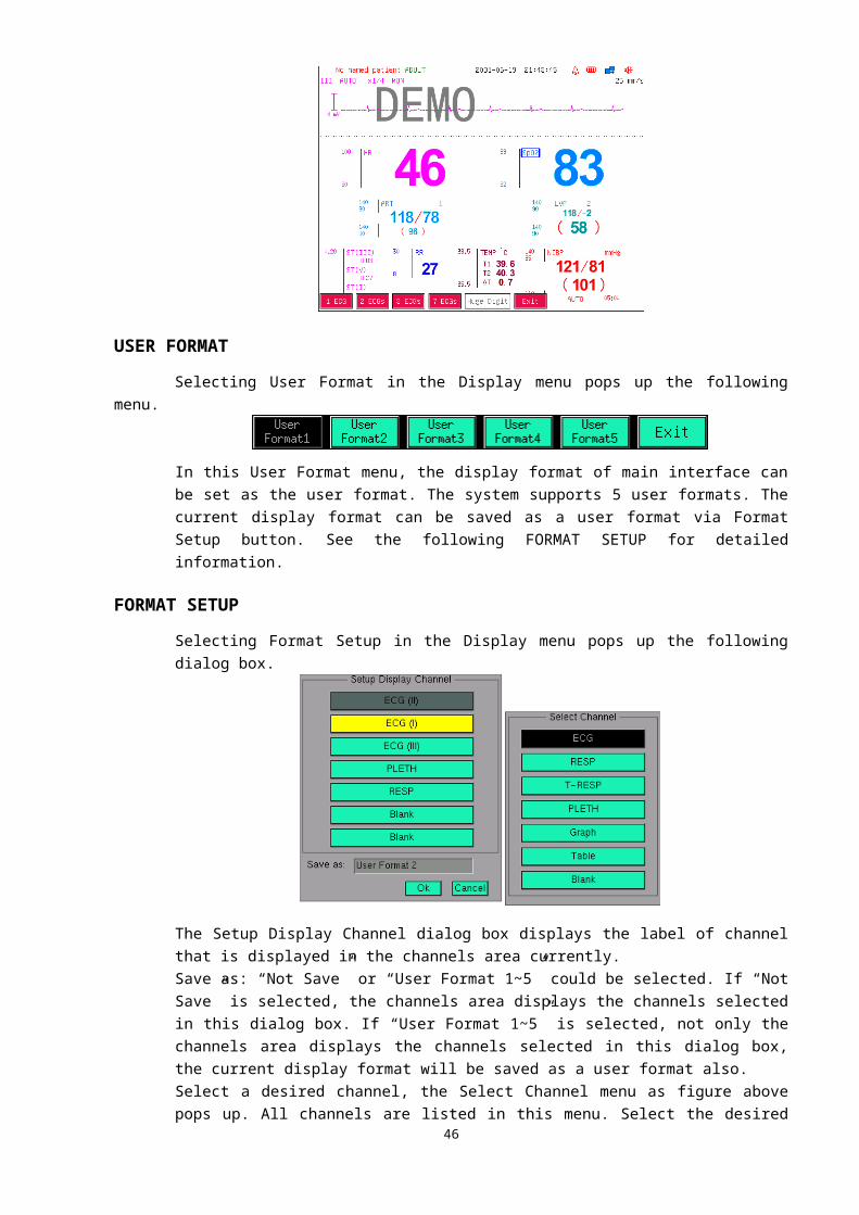
Set the IP address manually: Remove the selection of “Use dynamic IP configuration (DHCP)”, and then select the input field on the right side of “IP address” to set it manually. Select Ok button to confirm the selection, the monitor IP address will not change.
ServerSelecting Server in the Network Settings menu pops up the Server Setup dialog box where the address of the central monitoring system server can be set, shown as below.
■ Auto: The monitor searches the address of the server automatically.■ IP address: Input the IP address of the server manually.■ Domain Name: Input the domain name of the server via soft keyboard, such as
http://szmedtech.com.
Device NameSelecting Device Name in the Network Settings menu pops up the Edit Device Name dialog box, shown as below.
The device name of the monitor can be set in this dialog box. If the monitor is not named, it shows “No Name”.
MAINTENANCESelecting Maintenance in the System Setup menu pops up the following menu.
Reserved 1 and Reserved 2 are the manufacturer maintenance buttons, which the user dosen’t need to use.
System StatusSelecting System Status in the Maintenance menu pops up the following menu to view and check the relevant information of the system.
Main Settings
Selecting Main Settings in the System Status menu pops up the following Settings List information box where all the parameters and patient setting information can be viewed and checked.
47

Alarm Limits
Selecting Alarm Limits in the System Status menu pops up the following Alarm Settings information box where the upper alarm limits, lower alarm limits and alarm switches of all the parameters can be viewed and checked.
Software Version
Selecting Software Version in the System Status menu pops up the following Software Information box.
In this information box, the Serial NO., GBA440 (ARM) board software version, GAA718 board software version, KERNEL software version, GBA440 start time and Oximeter board software version can be checked.
48
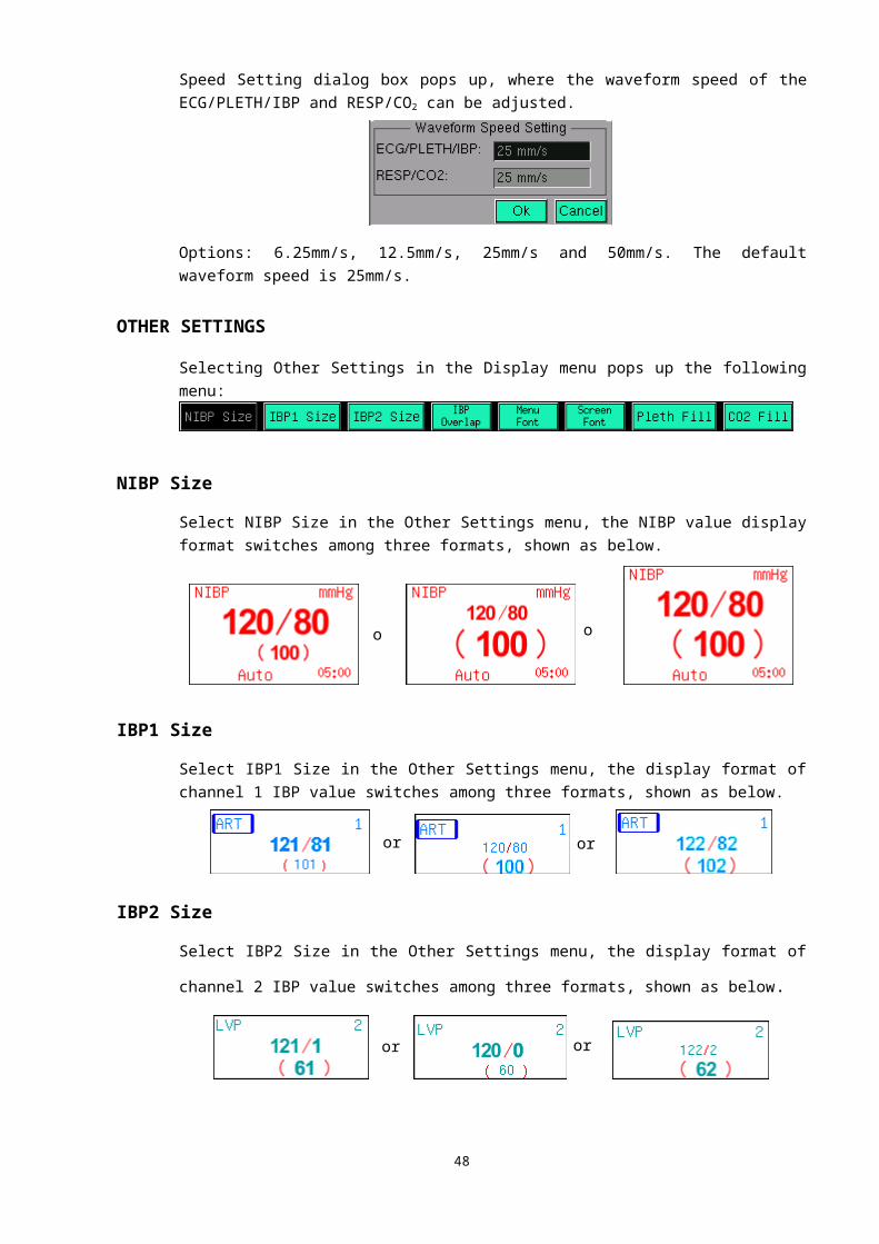
Remote Maintenance
WARNING● The remote maintenance must be carried out by personnel trained and authorized by our
company only.
This button is used for software upgrade.New software version to improve the performance or add new function is subject to issued without prior notice. If you need to upgrade the software, please follow the procedure specified below.1. Install the software upgrading program “Monitor Maintenance”.2. Connect the network connectors of the monitor and of the PC with TIA/EIA568B network
cable.3. Power on the monitor, press Remote Maintenance button in the Maintenance menu and hold for
5 seconds, the Remote Maintenance Service interface appears, shown as below.
■ DHCP: Select this button, the server distributes an IP address to the monitor automatically.■ Set NET: Select this button to set the IP address manually.■ Connect Server: Select this button to connect the monitor to the server. If connect
successfully, the lower left part of the interface shows a green field with word Connected on it, while unsuccessfully, shows a red field with word Connecting on it.
■ Return Monitor:Select this button to return to the monitoring mode.■ Disconnect: Select this button to disconnect the monitor with the server, and the lower left
part of the interface shows a yellow field with word Disconnect on it.CONNECT INFORMATION area at the lower right part of the interface displays the operation information, where you can check whether an operation is successful.
4. Run “Monitor Maintenance” program, and follow the procedure specified in the Software Upgrade Manual to upgrade.
5. After finishing the upgrade, exit the “Monitor Maintenance” program and select the Return Monitor button to return to the monitoring mode.
Please contact the Customer Service Department for the “Monitor Maintenance” program (with Software Upgrade Manual).
49
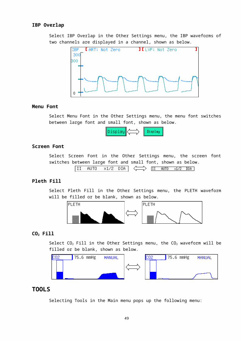
DemoSelect DEMO in the Maintenance menu, the system enters the demonstration mode. In this mode, the monitor simulates the wavforms and parameters in real use, and displays word DEMO on the screen. The purpose of the demonstration mode is to demonstrate the performance of the monitor, and for training purposes.
WARNING● In clinical applications, this function is forbidden because the DEMO status can mislead
the medical staff to treat the DEMO waveforms and parameters as the actual data of the patient. This may result in serious injury to the patient, or a delay of treatment or improper treatment.
DEFAULT SETTINGSSelecting Default Settings in the System Setup menu pops up the Set Default Settings dialog box, shown as below.
Select Ok, the system reverts to the default settings.
RECORDER SETUPSelecting Recorder Setup in the Main menu pops up the Set Printer Parameters dialog box, shown as below.
■ Curve Mode: Printing mode of the curve.“Mode 1”: Print an electrocardiogram waveform, namely the main lead ECG waveform.“Mode 2”: Print two waveforms, namely the main lead ECG and PLETH waveforms.
■ Curve Speed: Printing speed. Options: 12.5mm/s and 25mm/s.
50
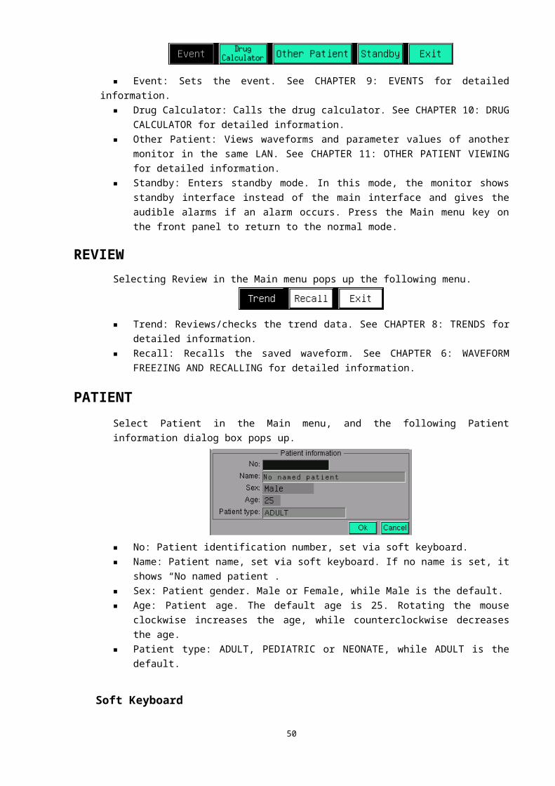
■ Total (Seconds): Waveform printing time. It can be selected in the range from 5 to 30 seconds.■ Alarm Print: Alarm printing switch.
Open: The printer automatically prints all the measured parameter values when the physiological alarms occur.
Close: The printer doesn’t print any measured parameter value when the physiological alarms occur.
■ Timer Print: Timer printing switch. Open: The printer automatically prints all the measured parameter values at the preset interval.Close: The printer dosen’t print any measured parameter value automatically.
■ Interval: The interval time between two printings, which can be selected in the range from 1 to 60 minutes.
The default settings for the “Alarm Print” and “Timer Print” both are “Close”.Refer to CHAPTER 7: PRINTING for detailed information.
CHAPTER 5: ALARMS
The monitor gives audible or visual alarms to indicate the medical staff, when a vital sign of the patient appears abnormal, or mechanical or electrical problems occur to the monitor.
ALARM CATEGORIESThe alarms are divided into two categories:
Physiological alarmsA physiological alarm either indicates that a monitored physiological parameter is out of specified limit or indicates an abnormal patient condition.
Prompt informationBesides the physiological alarm, the monitor also displays the information related to the system. For example, if a parameter module is turned on but the required leads or sensor are not connected, the monitor will prompt accordingly, such as “Lead Off” in the ECG and RESP channels, “Sensor Off” in the PLETH channel, or “No Cuff” under the NIBP parameter, etc. Prompt information is usually displayed in the channels area. But the prompt information relating to NIBP is displayed under
51

the NIBP value in the parameters area.
ALARM MODESWhen an alarm occurs, the monitor raises the user’s attention by the following audible or visual indications.
Visual alarmsWhen a measured physiological parameter value exceeds the preset alarm limit, the alarm indicator on the front panel flashes in red once a second.
Audible alarmsWhen a measured physiological parameter value exceeds the preset alarm limit, the monitor phonates a triple-beep tone each three seconds to prompt users.
Character flashesWhen a measured physiological parameter value exceeds the preset alarm limit, or a lead or sensor is disconnected to the monitor, this parameter value in parameters area or the prompt information in the corresponding channel flashes once a second.
ALARM SETTINGS
SETTING ALARM VIA ALARM KEYPress the Alarm key on the front panel of the monitor, the following Alarm menu pops up:
Alarm On/OffEnables or disables the physiological alarms.
Alarms enabled: Icon is displayed in the status bar, the physiological alarms are turned on, and
the monitor alarms when a measured paratmeter value exceeds the preset alarm limit.
Alarms disabled: Icon is displayed in the status bar, the physiological alarms are turned off,
and the monitor does not generate alarms even if the measured parameter value exceeds the preset alarm limit.
Alarm SettingsSelect Alarm Settings in the Alarm menu, the following Set Alarm Limits dialog box pops up:
The upper alarm limit, lower alarm limit, alarm switch and alarm printing switch of each pararmeter in different patient type can be set in this dialog box.■ Patient Type: ADULT, PEDIATRIC or NEONATE.
52
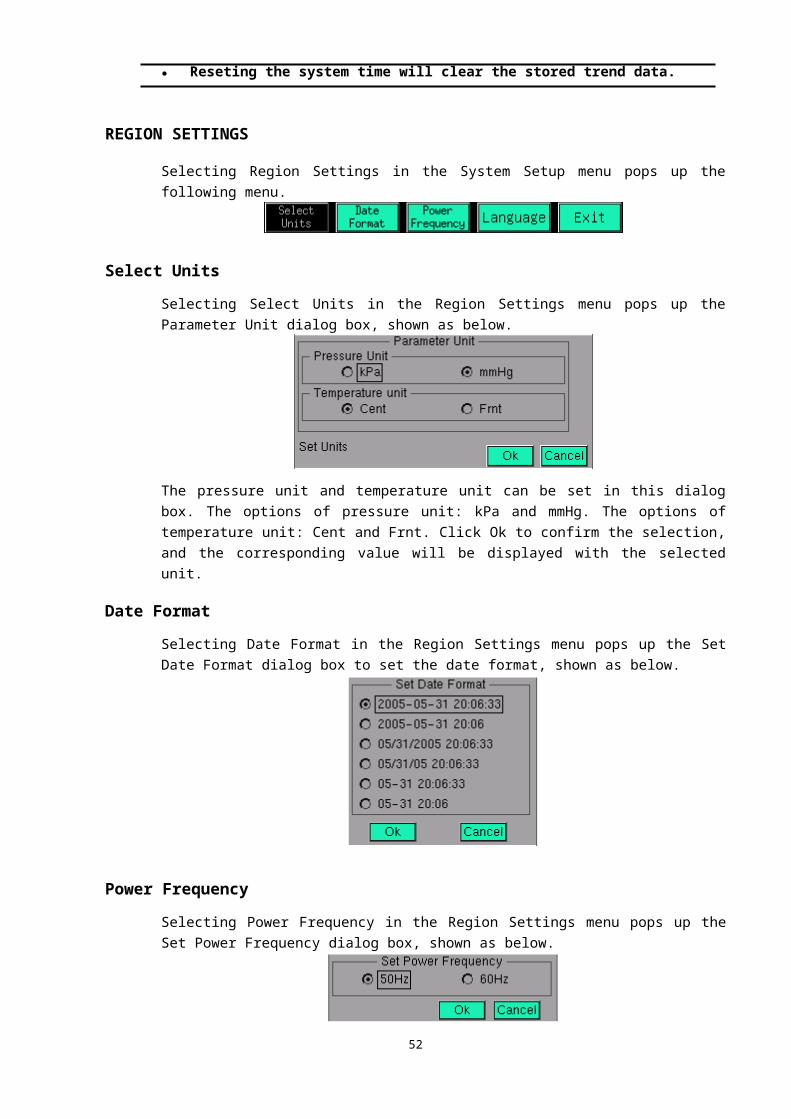
■ Params: HR, SpO2, NIBP, RESP, TEMP, ST, IBP1, IBP2, FiCO2 or EtCO2.■ High: Upper alarm limit.■ Low: Lower alarm limit.■ The input field on the right side of the lower alarm limit: Enables or disables the alarm of this
parameter and doesn’t affect the alarms of other parameters.On: The alarm of this parameter is turned on, and the monitor alarms when this measured
parameter value exceeds its preset alarm limit.Off: Icon “ ” is displayed on the left side of this parameter label, the alarm of this parameter
is turned off, and the monitor does not generate alarms when the measuared value of this parameter exceeds its preset alarm limit.
■ Print: Enables or disables the alarm printing of this parameter.On: The alarm printing of this parameter is turned on, and the printer prints all the measured
parameter values automatically when this parameter alarm occurs.Off: The alarm printing of this parameter is turned off, and the printer dosen’t print any
measured parameter values when this parameter alarm occurs.
Alarm ToneSelect Alarm Tone in the Alarm menu, the following Set Pulse & Alarm Tone dialog box pops up.
The pulse tone and alarm tone can be set separately in this dialog box. Input the tone value and select Test, the monitor will phonate the corresponding test tone. Select Ok to confirm the setting.
Default LimitSelect Default Limit in the Alarm menu, the following Set Alarm Default Settings dialog box pops up:
Selecting Ok in this dialog box sets all the alarm limits as their default values and enables the alarm of each parameter, but doesn’t change the status of the physiological alarms.
SETTING ALARM VIA PARAMETER LABELSelecting a parameter label pops up the corresponding menu. Although the menu of each parameter is different, all the menus have the same Alarm On/Off and Alarm Settings buttons to set the alarm limits separately.For example, select the HR label in the parameters area to pop up the HR menu, shown as below.
■ Alarm On/Off: Enables or disables the HR alarm. Alarm enabled: The HR alarm is turned on and the monitor alarms when the measured HR value exceeds its preset alarm limit.Alarm disabled: Icon “ ” (red) is displayed on the left side of the HR label. The HR alarm is
53
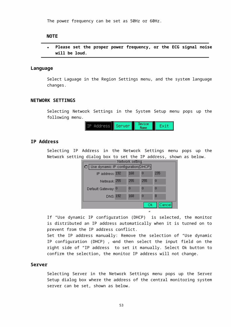
turned off, and the monitor does not generate alarms when the measured HR value exceeds its preset alarm limit.
■ Alarm Setting: Select this button, the following Set Alarm Limits dialog box pops up:
The Patient Type and Params cannot be changed in this dialog box.● High: Upper alarm limit. Determines the upper HR alarm limit.● Low: Lower alarm limit. Determines the lower HR alarm limit.● The input field on the right side of the lower alarm limit: Enables or disables the HR
alarm.On: The HR alarm is turned on, and the monitor alarms when the measured HR value
exceeds its preset alarm limit.Off: Icon “ ” is displayed on the left side of HR label, the HR alarm is turned off, and
the monitor does not generate alarms when the measured HR value exceeds its preset alarm limit.
● Print: Enables or disables the HR alarm printing.On: The HR alarm printing is turned on, and the printer prints all the measured parameter
values automatically when a HR alarm occurs.Off: The HR alarm printing is turned off, and the printer dosen’t print the measured
parameter values when a HR alarm occurs.The functions of other buttons in the HR menu are specified in CHAPTER 12: ECG MONITORING.
WHEN AN ALARM OCCURS
WARNING● When an alarm occurs, always check the patient’s condition first.
When an alarm occurs to the monitor, refer to the following steps and take action properly.
1. Check the patient’s condition.2. Identify the alarming parameter and the alarm category.3. Identify the cause of the alarm.4. Take action to remedy the alarm cause.5. Check if the alarm is cleared.
54

Chapter 6:
WAVEFORM FREEZING AND RECALLING
OVERVIEWYou can freeze the monitored waveforms of a patient as desired and view the waveforms of 15 seconds to gain a clear observation. The freezing and recalling function of the monitor have the following features.■ When the monitor enters the frozen mode, it exits all other menus
automatically.■ The system freezes all waveforms displayed in the channels area.■ At most, the frozen waveforms saved in the last 8 times can be recalled.
FREEZING AND UNFREEZING
WAVEFORM FREEZINGPress the Freeze key on the front panel, all the waveforms displayed on the screen are frozen, the system exits all displayed menus (if displayed), and the following menu pops up.
55
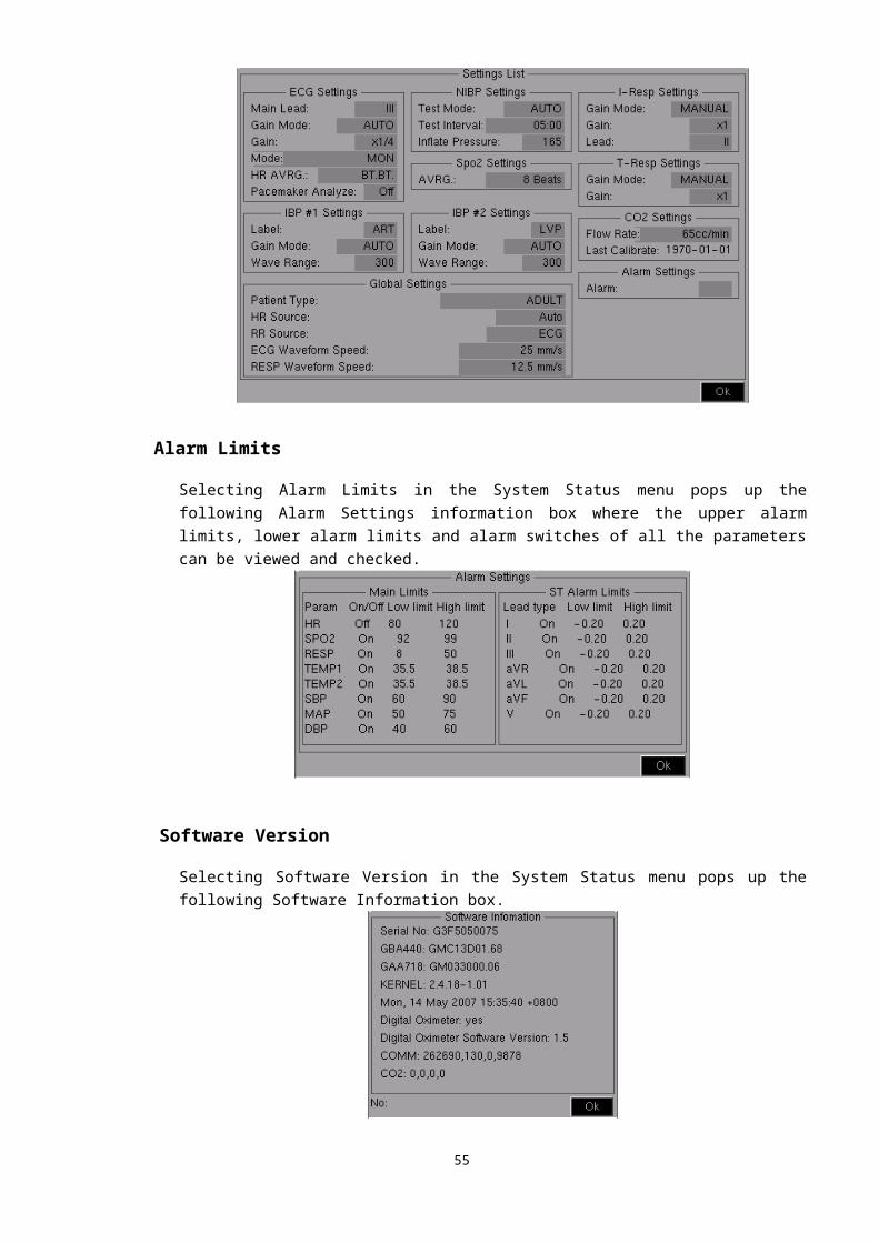
■ Last Page, Next Page: Turns the waveforms forward or backward to view the waveforms of 15 seconds before freezing.
■ Save: Select this button to save the frozen waveforms. If the waveforms are successfully saved, the following menu appears.
WAVEFORM UNFREEZINGTo exit the frozen mode,■ Select “Exit” in the Freeze menu■ Press the Freeze or Main menu key on the front panel.After exiting the frozen mode, all waveforms on the screen are cleared and new real-time waveforms are displayed.
WAVEFORM RECALLINGEnter the Recall menu via the Review button, the waveforms saved at the last time and the following menu are displayed on the screen.
■ Select File: Select this button, the following Please select files dialog box pops up:
① The start time of the selected file; ② The selectable saved files.Move the cursor to position ② and select the desired file by turning the rotating mouse, then select Ok, the corresponding waveforms will be displayed on the screen.
■ Last Page, Next Page: Turn the waveforms forward or backward to view the waveforms of 15 seconds before freezing.
Select Exit in the Recall menu or press the Main menu key on the front panel to exit the recalling mode.
56
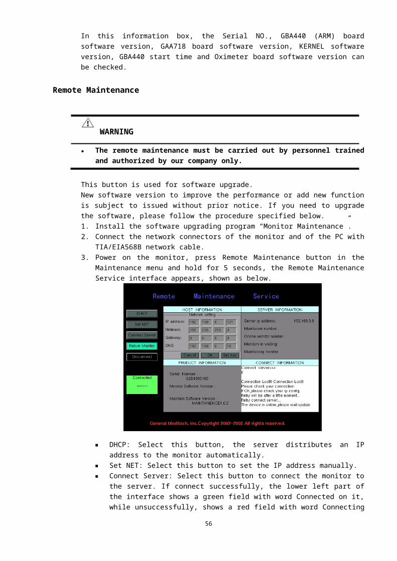
CHAPTER 7: PRINTING
OVERVIEWThe printer is an optional constitution for this monitor. If the monitor equipped with a printer, there is a Recorder Setup button in the Main menu for setting printer parameters.The performance of the printer is described as below.■ Prints patient information and parameters.■ Prints a maximum of two waveforms.■ The optional printing rates: 25mm/s and 50mm/s.■ Multiple printing types are supported.For details about the printer setup, please refer to RECORDER SETUP in CHAPTER 4.
PRINTING TYPES
The monitor supports the following types of printings:■ Real-time printing.■ Timer printing.■ Alarm printing.
57
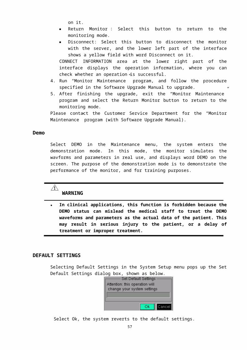
■ Trend graph printing (refer to TREND GRAPH WINDOW in CHAPTER 8).
REAL-TIME PRINTINGPress the Print key on the front panel, the real-time printing starts and the current waveforms are printed until the preset printing time is over or the Print key is pressed again, and then the measured parameter values at this moment are printed. As described in RECORDER SETUP in CHAPTER 4, you can set the Curve Mode, Curve Speed and Total in the Set Printer Parameters dialog box.
TIMER PRINTINGThe monitor starts printing all the measured parameter values at the preset interval.
ALARM PRINTINGThe monitor starts printing all the measured parameter values when the monitor generates physiological alarms.
NOTE● To realize the alarm printing of a parameter, the Alarm Print in Set Printer Parameters
dialog box, physiological alarms, and alarm and alarm printing of this parameter should be enabled.
● In working status, the printer cannot be configured.● If the interval arrives but the printer is in work, the monitor will give up the parameter
printing this time.
WAVEFORM AND PARAMETER PRINTINGPress the Print key on the front panel, the printer prints waveforms until the preset printing time is over, then prints all the parameter values measured at this moment, and then stops.Press the Print key to stop the current printing.
INSTALLING PRINTER PAPERThe printer used for this monitor is a special thermal printer that is installed on the side panel of the monitor in embedded mode, shown as the following.
58
Error indicator
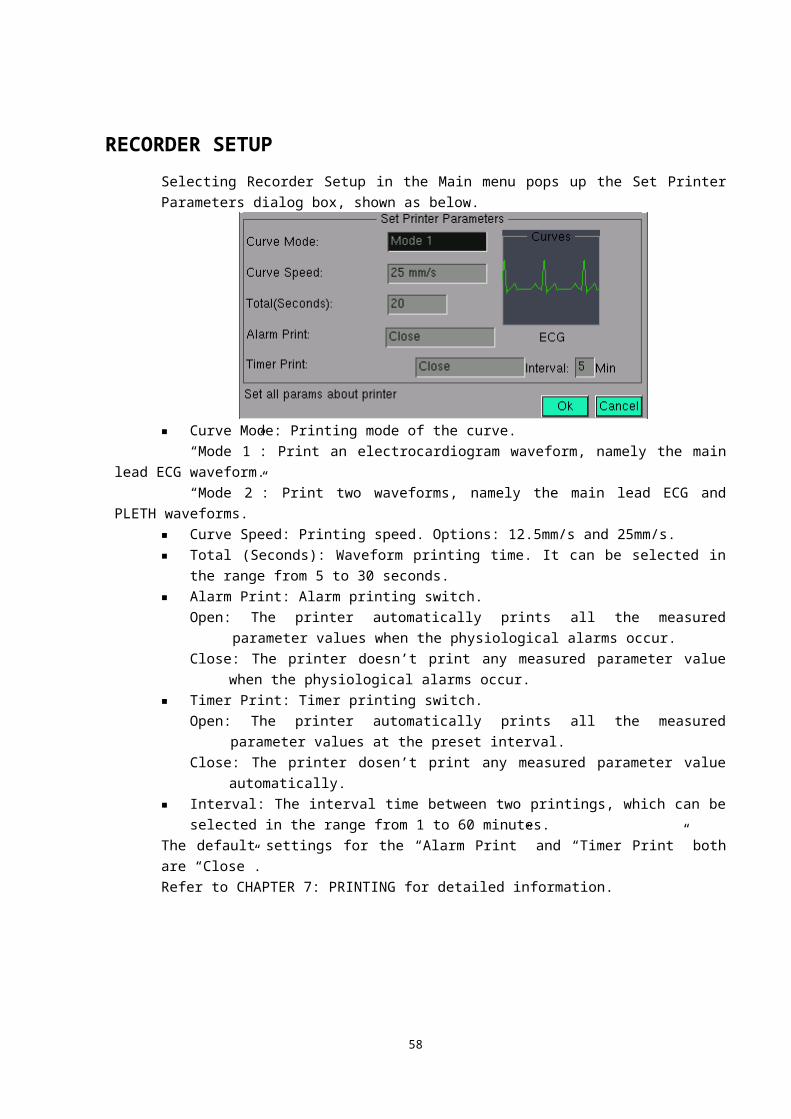
If the printer is properly installed, only the Power indicator lights on. If the Error indicator lights on, it indicates that the printer is in paper lack status or the paper has not been installed properly. Do not print at this time, or it will damage the printer. Follow the procedure below to install the printer paper.1. Press the latch above the paper compartment door to release the door.2. The printer paper is a single side thermal paper, and the smoother side that
has temperature sensitive coating on it shall be installed upside.3. Pull the end of the paper out of the compartment and close the printer door.
If the Error indicator lights off, the printer paper has been installed properly; if not, repeat the procedure specified above.
NOTE● Use the specified printer paper only. Other printer paper may cause the printer to print
with poor quality, function improperly or not at all, or bring damage to the thermal print head.
● If the printer is not properly connected, the information “Printer is not probed correctly!” will be displayed at the lower left part of the Set Printer Parameters dialog box.
● Do not open the printer door when the printer is in work.● Do not install any other types of printer to this monitor, otherwise the monitor will be
damaged. If you have any doubt, please contact the manufacturer in time.
CHAPTER 8: TRENDS
OVERVIEWThe trend data is the patient’s data collected along with the time accumulation. The trends function displays the patient’s status graph (trend graph) and status table (trend table) according to the trend data and can be used for reviewing the waveforms and parameter values at a certain time to judge and dispose about the patient’s status properly. If the monitor is equipped with a printer, the trend graph can be printed.
59
LatchPower indicator
ErrorPower
This monitor has two methods to display trend graph (table), one is to display it in channels area, and the other is to display it in trend window.
TREND CHANNELSThe trend graph (table) can be displayed in channels area, so that the waveforms, measured parameter values and their trend can be viewed at the same time. The trend graph (table) channel displays the latest real-time trend data distribution, and the parameters can be selected. Turn to the time concerned and adjust the time zoom spans.Press the Main menu key to enter the Main menu, select Display, and then select Format Setup to pop up the Setup Display Channel diaglog box. In this dialog box, select the Graph (Table), then select Ok, the trend graph (table) will be displayed in the channels area, shown as below.
TREND GRAPH CHANNEL
Distribution
① Parameter label: Select this label to enter the trend graph channel menu.② Measure scale: Mark the value scale on the trend graph.③ Trend graph area: The trend graph is displayed in the upper part, while the time scale in the
lower.In the ordinary status, the trend graph of the latest time quantumn is displayed in this area. When the data is more than one screen, the graph automatically rolls left. Select Last Page to review the earlier trend graph, and Next Page to review the later trend graph. The graph color is determined by the parameter. When the parameter value is void, its graph is grey.
60
Trend graphchannel
Trend table channel
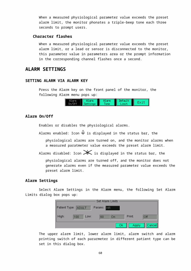
MenuSelecting the parameter label in trend graph channel pops up the following trend graph channel menu.
■ Select ParamSelecting Select Param pops up the following menu. Select the desired parameter in this menu, the corresponding trend graph will be displayed in the trend graph area.
■ Last Page and Next PageTurns the trend graph backward or forward.
■ StepSelecting Step pops up the following menu. The graph will be compressed and the new graph will be added according to the selected step.
■ RangeSelecting Range pops up the following menu.
The ordinate value range of the trend graph can be set in this menu. When the range is set, the trend data takes it as the upper limit/lower limit, and the value exceeds the limit is void.● Alarm Limit: Take the values about the default alarm limits as the range. It is the default
ordinate range.● Max Range: Take the default maximum and minimum values as the range.● Manual Adjust: Adjusts the range by turning the rotating mouse manually. But this range is
confined by the Max Range.
TREND TABLE CHANNEL
Distribution
① Table label: Select this label to enter the trend table channel menu.② Data area: In the ordinary status, the trend data of the latest time quantum is displayed in this
area. When the data is more than one screen, it automatically rolls up. The Last Page, Line Up, Line Down and Next Page buttons can be used to review the trend data of the time concerned.
61
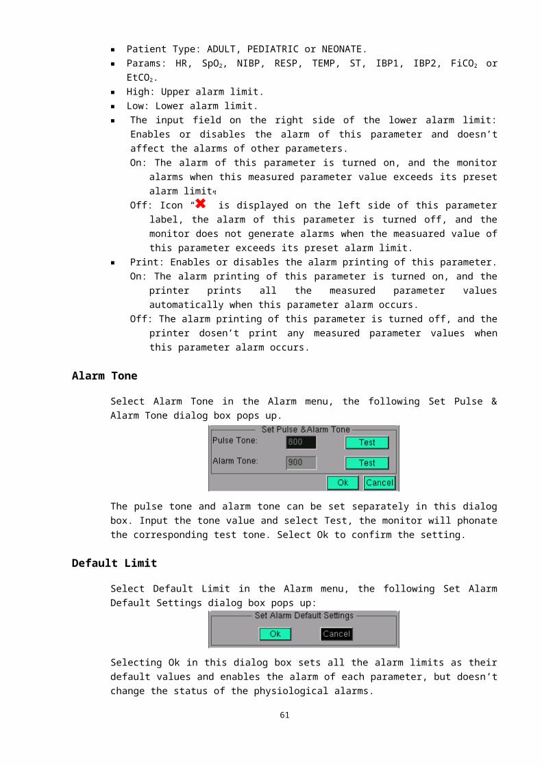
MenuSelecting the table label pops up the following trend table channel menu.
■ Line Up, Line Down, Last Page and Next PageAdjusts the time of trend data forward or backward.
■ StepSelecting Step pops up the following menu. The data will be compressed and the new data will be added according to the selected step.
TREND WINDOWSSelect Review in the Main menu, then select Trend, the trend graph window pops up. It can be changed to trend table window via the Table button in the displayed menu.
62

TREND GRAPH WINDOW
Distribution
① Parameter mark: The corresponding parameters of the three graphs displayed in the trend graphs area.
② Scale: Marks the value range of the trend graph.
③ Cursor: Move this cursor via the Cursor button.
④ Parameters table: The parameter values at the current time are displayed in this table. The inverse black text is the selected parameter, and the lower part of the list is the event and step. If there is a recorded event at the current time, the event number will be displayed on the right side of Event. The current step is displayed on the right side of Step. See CHAPTER 9: EVENTS for detailed information about the event.
⑤ Trend graphs area: Displays the trend graph of the selected time quantum. The graph color is determined by the parameter. When the parameter value is void, its graph is grey.
⑥ Starting time of the trend data: The time that the monitor starts to record the trend data.
⑦ Current time: The corresponding time of the cursor positon.
⑧ End time of the trend data: The time that the monitor stops recording the trend data.
⑨ The mark of the current time in the trend data record time: Marks the positon of the current time in the whole trend data record time with red point.
⑩ Event mark: Marks the event recorded in the current page with point in different color. Yellow point marks event 1, green point marks event 2, blue point marks event 3 and pink point marks event 4. See CHAPTER 9: EVENTS for detailed information.
⑾ Time scale: Marks the time scale of the current page.
MenuThe trend graph window menu is displayed as the following:
63
■ Select ParamSelecting Select Param pops up the following menu. One to three desired parameters could be selected in this menu. The selected parameter is displayed with inverse figure in the parameters table. Selecting a parameter again will cancel the selection. Select OK to confirm the selection, and the corresponding trend graph will be displayed.
■ Last Page and Next PageTurns the trend graph backward or forward.
■ CursorSelect Cursor and rotate the mouse, the cursor on the trend graph will move in accordance with the rotating direction, and the parameter values and events will be displayed in the parameters table. Pressing the rotating mouse again will exit the cursor moving status.
■ StepSelecting Step pops up the following menu. The graph will be compressed and the new graph will be added according to the selected step.
■ RangeSelecting Range pops up the following menu.
The ordinate value range of the trend graph can be set in this menu. When the range is set, the trend data takes it as the upper limit/lower limit, and the value exceeds the limit is void.● Alarm Limit: Take the values about the default alarm limits as the range. It is the default
ordinate range.● Max Range: Take the default maximum and minimum values as the range.● Manual Adjust: Adjusts the range by turning the rotating mouse manually. But this range is
confined by the Max Range.
■ PrintSelecting Print pops up the following menu.
In this menu, you can select to print the trend graph of current page, last 8 hours, last 12 hours or last 24 hours. Only the trend graph displayed on the top part of the trend graphs area is printed.
64
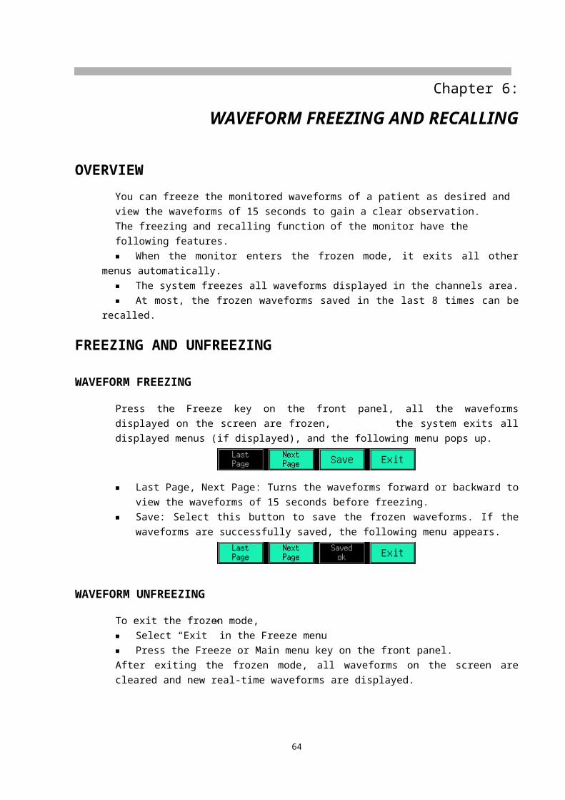
TREND TABLE WINDOW
Distribution
The DAY-TIME is displayed on the left part of the trend table. On the top is the latest time. From the upper to the lower, the interval between two adjacent times depends on the preset step. The central time of the table is the current time of the trend graph. The right of the DAY-TIME is the parameter names and parameter day-time values (except NIBP which is the first value in the current step). The symbol "---" means the parameter is not measured at the corresponding time.
MenuThe trend table window menu is displayed as the following:
■ Line Up, Line Down, Last Page and Next PageAdjusts the time of the trend data forward or backward.
■ StepSelecting Step pops up the following menu. The data will be compressed and the new data will be added according to the selected step.
■ GraphSelecting Graph enters the trend graph window.
65
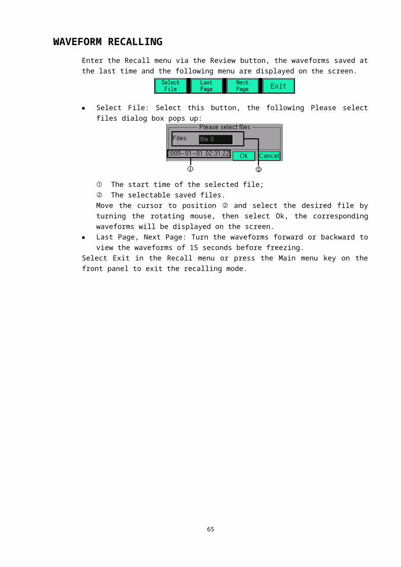
CHAPTER 9: EVENTS
This monitor provides events to define the situations, such as dose taking, injections or therapy, which have influence on patients and parameter monitoring. A mark will be displayed on the trend graph window indicating the time the mark was initiated in relation to the event it represents.
RECORD EVENTSSelecting Event in Tools menu pops up the following Events dialog box.
① The events to be recorded.② Prompt information.This dialog box allows you to mark four different events. Select Event 1, Event 2, Event 3 or Event 4, the monitor will record corresponding events.For example, if the injection is defined as event 1, when taking an injection, select Event 1, the monitor will record the current time and display prompt information “Set Event 1 OK” at the lower left part of the dialog box if records successfully.
BROWSE EVENTSThere is event point under the time scale on the trend graph window in different color to mark event. Yellow point marks event 1, green point marks event 2, blue point marks event 3 and pink point marks event 4. The Last Page, Next Page and Cursor buttons can be used for reviewing the time and parameter values when an event happens. For detailed information, see TREND GRAPH WINDOW in CHAPTER 8.
66

CHAPTER 10: DRUG CALCULATOR
The drug mixture used for intravenous transfusion involves the information such as the drug dosage, infusion speed, amount, volume, and concentration. The drug calculator can calculate the unknown value via the known items to help you to control the drug infusion.
WARNING● Before using any drug, you shall check whether the correct calculation unit or patient
weight have been selected, if have problems, please consult the dispensary in your hospital.
● It must be the doctor to determine the drug and its dosage. The drug calculator calculates the dosage based on the input values and cannot verify the validity of the calculated data.
ENTER DRUG CALCULATORSelect Tools in Main menu, and then select Drug Calculator, the following Drug Calculator window pops up.
UNITDrug unit
When the drug is “Any Drug”, g, mg, mcg, unit, k unit, m unit or mEq can be selected. When the drug is selected, the drug unit is set by the drug calculator automatically, and the user cannot modify it.When the drug unit is selected, the units relating to the weight in the Drug Calculator, Drip Table and Titration Table will change correspondingly.
67

Time unitOptions: min (minute) or hr (hour).When the time unit is selected, the units relating to the time in the Drug Calculator, Drip Table and Titration Table will change correspondingly.
TERMS Amount
The total weight of the drug used within certain time. Volume
The volume of the mixture is formed by drug diluents and drugs. Dose/min (Dose/hr)
The drug quantity injected in a minute or an hour. Dose/(kg*min), dose/(kg*hr)
The drug quantity injected into 1kg of patient weight in a minute or an hour.Dose/(kg*min) × Weight = Dose/minDose/(kg*hr) × Weight = Dose/hr
RateThe volume of the mixture injected in a minute or an hour. The unit is ml/min or ml/hr.
Rate/kgThe volume of the mixture injected into 1kg of patient weight in a minute or an hour. The unit is ml/min or ml/hr.Rate/kg × Weight = Rate
TimeThe consumed time for drug transfusion. The unit is min or hr.
ConcentrationThe concentration of the mixture formed by the drug diluents and drug.Concentration = Amount / Volume
Drip/min (Drip/hr)The gutta of the mixture transfused in a minute or an hour.
Drip/mlThe volume of each gutta dropped form the transfusion device. The unit is GTT.
DRUG CALCULATOR
NUMERIC INPUT BLOCK The number is inputted according to the digit. When entering the numeric input block, the
numeric input block selects the first digit at left, turn the rotating mouse, the numeric input block selects each digit consecutively from left to right, when it reaches the last, it jumps to the next input block.
The selection range for each digit is 0~9. When the digit is greater than the display value, it displays ---.--, and when it less than the
display value, it displays 0.00. When it cannot display all digits, the round is adopted.
CALCULATION FORMULA The relational formula of the drug weight
68
Amount = Dose/min × TimeDose/min = Dose/(kg*min) × Weight
The relational formula of liquid volume Volume = Rate × TimeRate = Rate/kg × Weight
Concentration = Amount / Volume
KNOWN ITEM AND CALCULATION RESULTS Amount, Dose/min, Dose/(kg*min), Volume, Rate, Rate/kg, Time and Concentration can be
inputted as the known items or be outputted as the calculation results. At least three known items should be inputted according to the calculation requirements, and
the drug calculator automatically calculates the item that has computation relationship with them.
The known item is expressed with digit in blue background, and the calculation result is expressed with digit in gray background.
When enters this window, all items are displayed as 0.00 and can be inputted. When a known item is inputted, the result will be displayed in real-time and locked, the user only can modify the known item. Modifying the input item as 0.00 means canceling this input.
The Reset button restores all the items to the initial status.
CALCULATION FOR ANY DRUG When the Drug selection is Any Drug, the Drug Calculator only provides the calculation with
no application range prompt for the dose, concentration etc. Input the Weight, Drug Unit and Time Unit. Input the kown item, and the drug calculator will calculate relevant item.
CALCULATION FOR EXACT DRUG The drug calculator has been preset more than ten general drugs calculation, including
Aminophylline and Amrinone Lactate (refer to Drug dosage range limitation table). When select the drug, the Concentration, Amount and Dose/min (or Dose/(kg*min)) have range limitations. If the input item or calculation result is out of the range, it will be expressed in yellow digit.
The drug dosage over range prompt only prompts the user to pay attention to use appropriate dose of the current drug, the final transfusion dose and transfusion process are determined by the doctor.
69
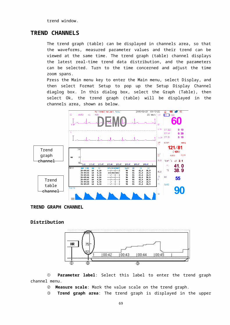
Drug dosage range limitation table
English name Concentration Dose/min (Dose/(kg*min)) AmountAminophylline ≤1mg/ml ≤25mg/min 250~500mg
Amrinone Lactate 1~3mg/ml 5~10ug/kg/min 250~500mgBretylium Tosilate ≤10mg/ml 1~50mg/min 5~10mg
Dobutamine ≤5mg/ml 2.5~40ug/kg/min ≤250mgDopamine ≤3mg/ml 1~30ug/kg/min 10~20mg
Epinephrine <64ug/ml 1~4ug/min 0.025~1mgHeparin Sodium 20~40U/ml 15~20U/kg/h±10% 6000~20000U
Isuprel 2~4mcg/ml 2~20mcg/min 500~1000mcgLidocaine ≤8mg/ml 1~4mg/min 50~100mgMorphine
hydrochloride≤5mg/ml ≤2mg/min 5~15mg
Nitroprusside ≤1mg/ml 0.5~10ug/kg/min ≤50mgNitroglycerin 50~400ug/ml 5~200ug/min 5~10mg
Oxytocin 0.01U/ml 0.001~0.04U/min 2.5~5UProcainamide 2~4mg/ml 1~6mg/min 500~750mg
DRIP TABLESelect Drip Table in the Drug Calculator window, the following information window appears that shows how much liquid is transfused and how much time remains. The Drip Table displays the residual quantities of the drug and liquor at each time quantum
when the user inputs the data into the Drug Calculator window. The left side of the widow shows the data inputted by the user (and calculation result) in the
Drug Calculator window, the right side lists the amount and volume at 15 time quantums that are equally divided from the Time.
All items in this window cannot be modified. In the table, the unit relating to the weight is the same as the unit in the Drug Calculator
window, and the volume unit is ml. Select Ok to exit the Drip Table window and return to the Drug Calculator widow.
70
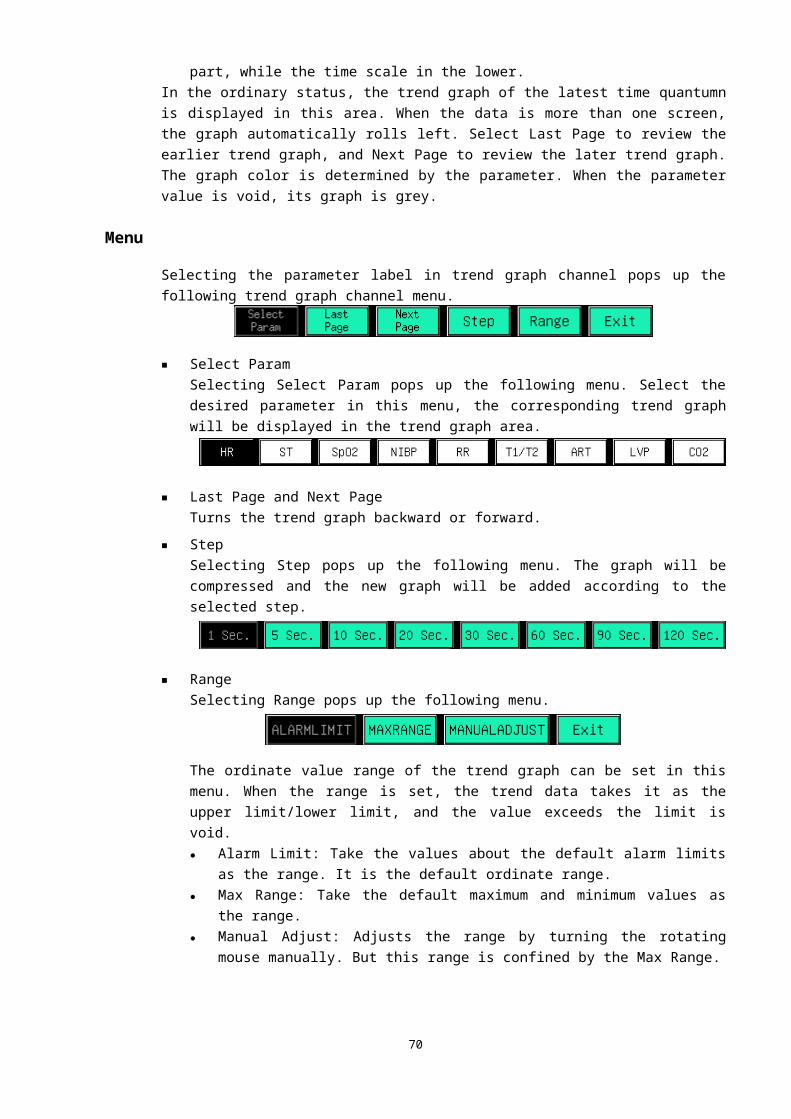
TITRATION TABLESelect Titration Table in the Drug Calculator window, the following information window appears that displays the dosage at different rates. The higher the rate is, the greater the steps between the items are. The Titration Table shows the dose (Dose/min or Dose/hr) at different rates with the same
concentration. The left side of the widow shows the data inputted by the user (and calculation result) in the
Drug Calculator window, the right side shows the dose (Dose/min or Dose/hr) at 30 rates, which are equally divided from the range in the benchmark item.
In the list the user has two items such as Dose and Rate. The range of Dose/min (Dose/hr) is the one to two times as the dosage inputted in the Drug
Calculator window. Select Ok to exit the Titration Table window and return to the Drug Calculator window.
RESETExit the Drug Calculator window or turn off the monitor, the drug calculator data inputted by the user and the calculation result are still saved. When the user enters the Drug Calculator window again, the latest calculator dada shows. Selecting Reset in the Drug Calculator window clears the inputted data and starts a new calculation.
71
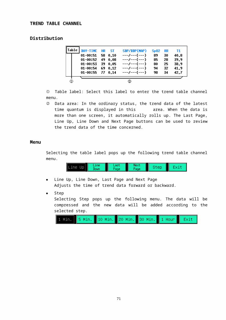
CHAPTER 11: OTHER PATIENT VIEWING
OVERVIEWThis monitor is able to view waveforms and measured parameter data from another patient monitor on the same monitoring network.The other patient viewing function has the following features:■ The other patient viewing function must be realized by the LAN, so the viewing and viewed
monitors should both be connected to the LAN.■ The LAN connection could be wire or wireless.■ The other patient viewing function doesn’t depend on the central monitoring system. Whether
the central monitoring system exists in the LAN doesn’t influence this function.■ A monitor only can view one monitor and at the same time, only can be viewed by one monitor.
SELECT MONITOR
Select Tools in the Main menu, and then select Other Patient, the following Other Patient--Select Monitor dialog box pops up.
■ All the device names of the monitors connected to the LAN are listed in this dialog box, such as “101” displayed in the figure above. The device name is set in the Edit Device Name dialog box and its detailed setting method refers to NETWORK SETTINGS in CHAPTER 4.
■ One page of this information box can list 12 device names. When the connecting monitors exceed 12 sets, the device names will be displayed in divided pages and can be checked via the Prev. and Next buttons that aren’t displayed if the connecting monitors are less than 12 sets.
■ When the viewed monitor alarms, its device name is in red background, and the button restores to blue background when the viewed monitor no longer has physiological alarms.
■ If the same device names exist in a LAN, they will be listed as “device name * serial No.” in
72
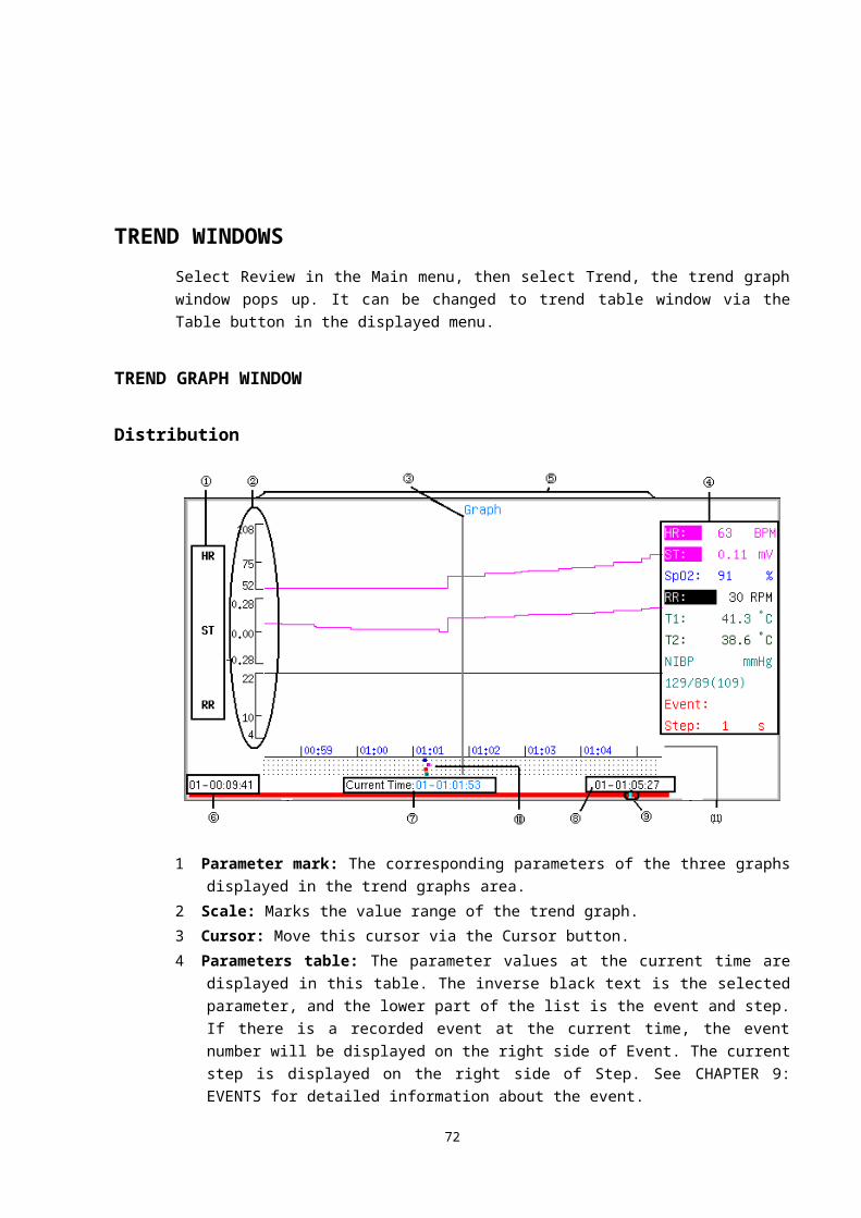
this dialog box.■ Turn the rotating mouse to select the desired device name, and then press the rotating mouse to
check the waveforms and parameter values of the corresponding monitor.■ This information box can’t exit automatically, you can select the Ok button or press the Main
menu key on the front panel to exit.■ A monitor only can be viewed by another monitor, if select a monitor viewed by another, the
Other Patient information box will pop up, shown as below (“101” is the selected device name).
OTHER PATIENTSelect the desired device name in the Other Patient—Select Monitor dialog box, the following window pops up.
■ All the real-time parameter values of the viewed monitor are displayed in the lower part of this window. If a parameter value exceeds the alarm limit of the viewed monitor, it will be displayed in red.
■ The parameter alarm doesn’t change the audible alarms status of viewing monitor. The parameter alarm is related with the alarm limit of the viewed monitor, and has no relation with the alarm switch, alarm tone of the viewed monitor and the relevant alarm settings of the viewing monitor.
■ A real-time waveform of the viewed monitor is displayed in the waveform area. There is a waveform selection field at the top left conner, select it, and the displayed waveform will switch among all the parameter waveforms.
■ This window can’t exit automatically, you can select the Ok button or press the Main menu key on the front panel to exit.
73
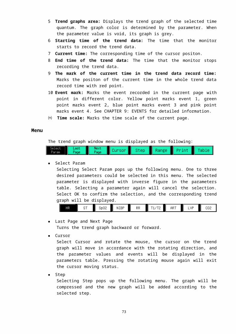
CHAPTER 12: ECG MONITORING
OVERVIEWThis Monitor adopts 5-lead (or 3-lead) ECG cable to collect the ECG signal from the patient, and it can simultaneously display seven (or three) leads of ECG signal. ECG channel displayed on the top part of the screen is the major channel of the ECG signal, and its lead is called the major lead. The Monitor calculates the heart rate value and controls the gain (if set in automatic mode) according to the data of the main lead. All leads adopt the same gain and same measurement mode. The Monitor can separately check whether the connection of a lead has fallen off, and display the promt information in corresponding channel.
1.Measurement of ECG The electro-chemical activity of “Excitable cell” will produce physiological current
to cardiac muscle before the mechanical shrinkage of heart, the close movement current produced by the process of heart exciting will flow within the human body and transport to all parts, it results in the different voltage on the different surface of body. The clinic Electrocardiography is to record the voltage difference real time.
Figure 2.1 is the Electrocardiography
R P
S
2.1 Figure1.1Electrode of ECG
Current within human body is conducted by hydronium, while it’s by electron in metal conductor, so there should be a conversion medium to convert the hydronium current to electron current, which will help realize the necessary connection between the human body and patient monitor, electrode is to play the role to realize the transformation. The widely used electrode for clinic monitoring is Ag—Ag.Cl disposable electrode.
1.2. ECG leadsThe definition of lead is the periodically changing waveform with heart beating
caused by the voltage between two or more than two surface parts of human body.One lead waveform can only reflect one aspect of the heart movement since the
74
uTQ
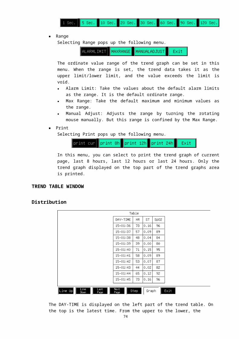
heart is solid, so it’s necessary to record several leads waveforms to reflect the complete movement of heart from different respects during the process of diagnosing. Below table is the definition for the different leads of ECG:
Table 2.1: Definition for different leads of ECG Name of leads Definition of leads Nominate of leads
Ⅰ =LA-RAⅠ Standard double poles limb leadⅡ =LL-RAⅡ Standard double poles limb leadⅢ =LL-LAⅢ Standard double poles limb lead
aVR aVR=RA-(LA+LL)/2 Pressure single pole limb lead
aVL aVL=LA-(LL+RA)/2 Pressure single pole limb lead aVF aVF=LL-(LA+RA)/2 Pressure single pole limb lead
Ⅴ V=V-(LA+RA+LL)/3 Pressure single pole limb lead
Our patient monitor adopts five leads ECG cable to collect signal of patient’s ECG. It displays synchronously seven ECG waveforms. The fixed channel of ECG displayed on the upper position is the main one of ECG signal, we call the ECG lead which the main channel choose “main lead”, patient monitor calculate the value of heart rate and control the gain based on it (if them monitor is set to model of “Auto gain”). We have the same gain control and test mode to all leads, the patient monitor is able to check whether the corresponding electrode of leads is fall off and display it on screen.
2.Monitoring of ECG electrode
It can get mostly twelve selectable ECG leads if use five leads ECG cable to monitor patient’s ECG, the ECG waveform of this lead of patient will be displayed when the leads is set as valid.
The ECG cable includes two parts: main stem cable which connected to patient monitor and Lead cable electrode which connected to patients, usually the ECG cable has five electrodes, please note below items when place the electrodes to patients:
1) How to choose and use electrodes
It usually chooses Ag-AgCL one-off electrode, please make sure the electrodes are during the period of validity. It will result in inaccurate data if use the incompetent electrodes.
2) Pretreatment of skin
It’s necessary to pre-treat the skin of patient to ensure the good touch between electrode and patient since the skin is not a good conductor.
(1) Clean the skin with soap and water instead of aether and alcohol since the later two will increase the resistance of skin.
(2) Shave off the fur of body where to place the electrode if necessary.
(3) Rub skin to increase the blood floor of capillary vessel of organization and get ride of the horn and grease.
75
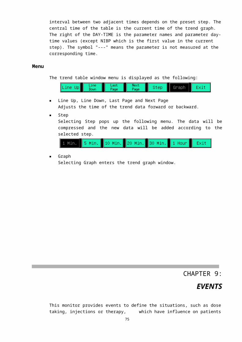
(4) Place the electrode to patient, please apply conductive cream before the electrode is put to patient if the electrode do not have conductive cream.
(5) Connect the electrode and ECG cable.
(6) Make sure the connection of patient monitor power.
ECG MONITORINGIn order to monitor the patient’s ECG, we use a five-electrode ECG cable by which we can get more than 12 selective ECG leads. If a lead is effective, the corresponding waveform will be displayed in the channels area.The ECG cable includes two parts: the main cable connecting the Monitor and the electrode lead line connecting the patient.
PREPARATION1. Select electrode
Generally, the electrode for monitoring is disposable electrode made from Ag-AgCl (silver - silver chloride). But before use, you shall confirm that the electrode is within the valid date. If the unqualified electrode is used, it will lead to inaccurate monitoring result.
2. Skin pretreatmentBecause the skin is not a good conductor, if you want to gain good contact between the skin and the electrode, before installing the electrode, you shall carry out skin pretreatment at first.(1) If necessary, shave hair from skin at choosen site.(2) Rub the skin to accelerate the blood flow in the blood capillary of organs and remove the
horny layer and greases of the skin.(3) Thoroughly cleanse the site with mild soap and water solution, but do not use the aether
or pure alcohol, because it will increase skin resistance.(4) Dry the skin completely before applying the electrodes.
3. Attach the ECG lead to the electrodes prior to placement.4. Place the electrode on the patient. If the conductive ointment is not applied to the
electrodes, apply it before the placement.5. Connect the electrode lead to the patient cable. 6. Confirm the Monitor is powered on and is ready for monitoring.
ELECTRODE PLACEMENT(1) For the placement of the five–lead ECG electrode, refer to the figure as shown in Figure 12-1.
76

Figure 12-1 Positions of 5-Lead Electrode Placement
NOTE● The sign name and color of the electrode shown above is American standard, while inside
the brackets ( ) is European standard.
■ White (right arm or RA) electrode: near the right shoulder, directly below the clavicle.
■ Black (left arm or LA) electrode: near the left shoulder, directly below the clavicle.■ Green (right leg or RL) electrode: on the right abdomen.■ Red (left leg or LL) electrode: on the left abdomen.■ Brown (chest or V) electrode: on the chest.
(2) When using five leads, attach the chest (V) electrode to one of the following positions indicated in Figure 12-2:
Figure 12-2 Positions of Chest Electrode
In order to accurately install and monitor the "V" lead, it is very important to determine the fourth rib position, which is determined according to the first rib position. Because of the patients’ different bodily forms, it is difficult to accurately feel out the first rib position. At first, feel out the small protruding body called the "Lewis angle", where the breastbone diaphysis and manubrium sterni joint. Then determine the second rib position, the protuberant section of the breastbone indicates the joint of the second rib, right under here is the position of the second rib position, from the chest to feel down until the fourth rib position is determined.Attach the chest (V) electrode to one of the following positions indicated in Figure 12-2:
77
● ●
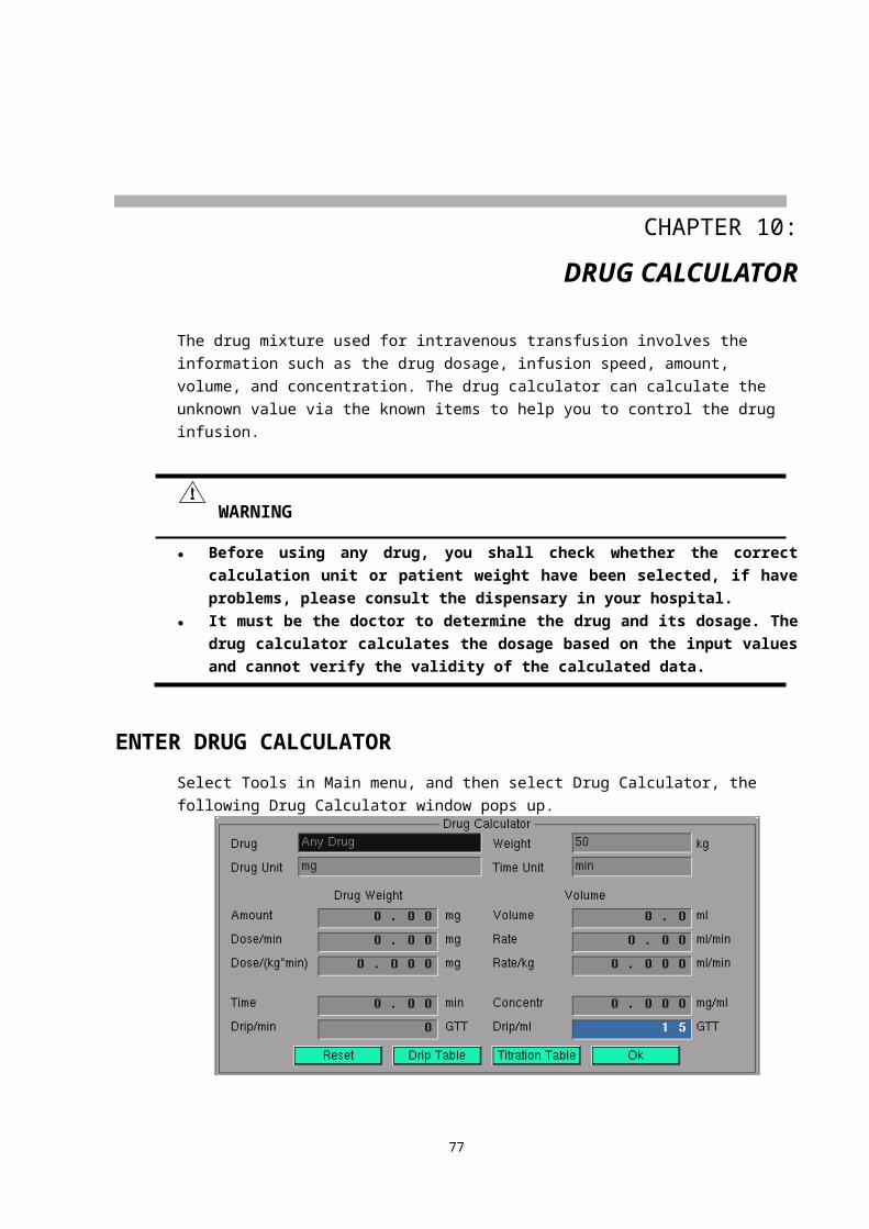
■ V1: On the 4th intercostal space at the right sterna margin.■ V2: On the 4th intercostal space at the left sterna margin.■ V3: Midway between V2 and V4 electrodes.■ V4: On the 5th intercostal space at the left clavicular line.■ V5: On the left anterior axillary line, horizontal with V4 electrode.■ V6: On the left middle axillary line, horizontal with V4 electrode.■ V3R-V7R: On the right side of the chest in positions corresponding to
those on the left.■ VE: Over the xiphoid.When attaching the chest electrode to the back of a patient, place it at one of the following sites:■ V7: On the 5th intercostal space at the left posterior axillary line of the
back.■ V7R: On the 5th intercostal space at the right posterior axillary line of
the back.
(3) Electrode placement for pacemaker patientThe pacemaker lead can pick up the best ECG waveform from the pacemaker patient. At this time, the electrode is usually placed on the mammillary line, the white and black electrodes are placed as shown in Figure 12-3.
Figure 12-3 Positions of Pacemaker Patient’s Electrode
(4) Electrode placement for surgical patientElectrode placement during surgery is dependent on the type of surgery being performed. For example, with open chest surgery, the electrodes might be placed laterally on the chest or on the back. In the operating room, artifact can sometimes affect the ECG waveform due to the use of electrosurgery equipment. To help reduce this, place the electrodes on the right and left shoulders, the right and left sides near the stomach, and place the chest lead on the left side at mid-chest. Avoid placing the electrodes on the upper arms. This will cause the ECG waveform to be too small.
NOTE● Select the place with stable ECG signal or little inference of skeleton activities to place the
78
White (red) Black (yellow)
Red (green)
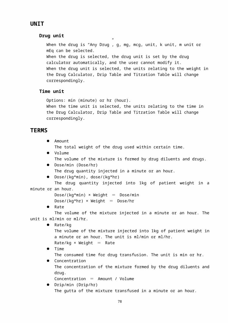
electrodes.
WARNING● In order to ensure the patient’s safety, all leads shall be connected to the patient.● The electrode shall be fixed properly to ensure the reliable contact of the conductor with
skin.● Interference from a non-grounded instrument near the patient and ESU interference can
cause inaccuracy of the ECG waveform.● When using Electrosurgery equipment, never place the ECG electrodes near the
grounding plate of the Electrosurgery device. This will cause a great deal of interference with the ECG signal. The patient leads should be placed in a position that is equal distance from the Electrosurgery electrotome and the grounding plate to avoid burns to the patient.
● Always dispose of, or recycle electrodes properly to prevent from environment contamination.
● Verify the lead fault detection prior to the start of monitoring. Unplug the ECG cable from the ECG connector, the flashing error message “Lead Off” will be displayed in the corresponding ECG channel.
● Skin irritation may result from the continuous application of the ECG electrodes. These should be checked each day. If there is an indication of excess skin irritation, replace the electrodes or change the location of the electrodes every 24 hours.
ECG CHANNEL
MAIN LEAD CHANNELThe top part of the channels area that cannot be changed to any other channels is called as the main lead channel, shown as below:
①Main lead label ②gain mode ③gain ④measurement mode⑤Waveform speed ⑥ECG waveform ⑦scale range ⑧scale
Select the main lead label, the ECG channel menu shows as the following.
■ Lead
79
① ② ③ ④ ⑤
⑧
⑦⑥

Select this button, the main lead switches among I, II, III, aVR, aVL, aVF and V. In order to get accurate heart rate and gain control performance, the doctor shall select the lead of large range and little noise as the main lead. In order to avoid emerging leads repeatedly, when the lead in the current channel is switched, the leads in the other channels will be changed automatically.
■ Gain ModeSelect this button, the gain mode switches between AUTO and MANUAL modes.Gain means the magnification times for the ECG waveform signal. This monitor has five magnification times that are ×1/4, ×1/2, ×1, ×2 and ×4. The ×1 is one time magnification, under which the range ⑦ of the scale ⑧ at the left side of the ECG waveform is 1mV. Then under the condition of ×2 magnification, the range ⑦ of the scale ⑧ is 0.5mV, and so on. Detailed data refers to the following table:
Gain factor AUTO MANUAL Scale range×1/4 Adopted Applicable 4 mV×1/2 Adopted Applicable 2 mV×1 Adopted Applicable 1 mV×2 Adopted Applicable 0.5 mV×4 Adopted Applicable 0.25 mV
Under 1 ECG and Huge Digit display format, the length of the scale ⑧ is 10mm. The waveform of 10mm diaplayed under ×1 magnification times means the ECG signal is 1mV, under ×2 means 0.5mV.
NOTE● All leads including the main lead and other leads adopt the same gain.
This Monitor provides two methods to regulate the ECG waveform range:● AUTO mode: Under the AUTO mode, according to the main lead waveform data, the
Monitor will automatically regulate the gain to amplify the ECG waveform of the main lead without the distortion as possible. The defect of this mode is slow regulation speed.
● MANUAL mode: Under this mode, the Monitor doesn’t regulate the ECG gain automatically. At this time, the ECG gain is regulated via the Adjust Gain button. The feature of this mode is fast response that the waveform will change immediately after the gain is regulated, and the waveform can be amplified to a distortion status to display.
■ Adjust GainManually regulates the ECG gain. After selecting this button, regulate the gain via the rotating mouse. Rotate counterclockwise, the gain and waveform range become smaller, while rotate clockwise, the gain and waveform range become larger. After the accomplishment of the regulation, press down the rotating mouse again to exit the gain adjusting mode.
■ ModeThe Mode means the filter bandwidth of the ECG channel. The monitor has three modes: diagnosis (DIA), monitoring (MON) and operation (OPR). Under the DIA mode, the filter bandwidth is the widest, and the detailed information of the ECG signal can be got. The more detailed information is helpful to more accurately judge the status of the ECG signal. But when the importation of the detailed information, the environmental noise, such as HF electrotome,
80

may be imported too. The noise mixes with the real ECG signal, so that the ECG signal cannot be distinguished. In order to adapt to the noise interference situation, the Monitor also provides two measurement modes, namely the MON mode and the OPR mode. Under these two modes, narrower bandwidth is adopted to measure and gain smoother signal. The user can make choices according to the exact situations, and the comparing data are as followings:
Mode Bandwidth Details NoiseDIA 0.05Hz~100Hz Most Most
MON 0.5Hz~40Hz Medium MediumOPR 1.0Hz~25Hz Least Least
NOTE● All leads including the main lead and other leads adopt the same mode.
■ Waveform SpeedSelect this button to regulate the waveform speed for parameters relating to ECG, including all ECG channels and PLETH channel. It has four speeds such as 6.25 mm/s, 12.5 mm/s, 25 mm/s and 50 mm/s.
OTHER LEAD CHANNELS
①Other lead label ②scale ③lead off icon ④ECG waveformSelect the position ①, the current lead label switches among 6 leads (except the main lead). Labels in different channels are different, when the lead label in the current channel is switched, the lead label in other channels will be changed automatically.When the ECG electrode has fallen off from the ECG cable or from the monitor, the flashing prompt information “Lead Off” is displayed in corresponding ECG channel.
ECG PARAMETER
HEART RATEExcept in Huge Digit mode, the heart rate is displayed on the top part of the parameters area, shown as below.
①Lower alarm limit ②Upper alarm limit ③alarm off icon ④heart rate label ⑤heart rate source sign ⑥Measured heart rate value
81
① ② ③ ④
③ ④ ⑤
①
②
⑥
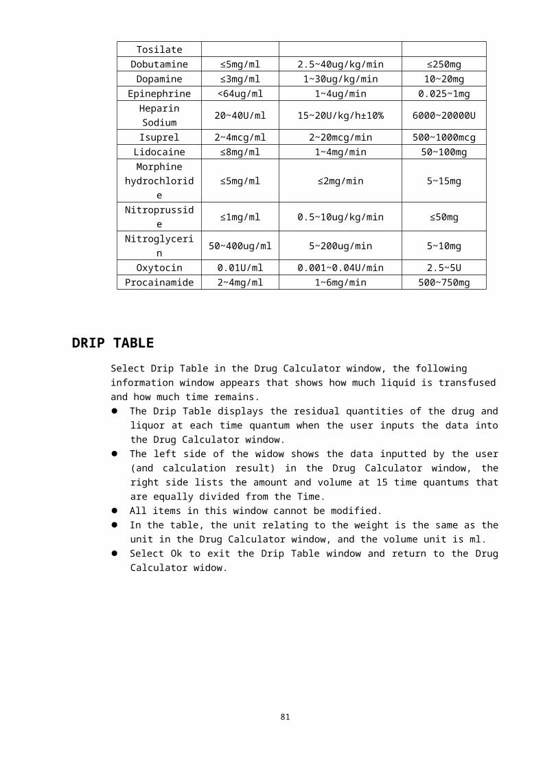
Select the heart rate label (HR), the HR menu pops up, as shown in the figure below:
■ Alarm On/OffEnables or disables the HR alarm.Alarms enabled: The HR alarm is turned on and the monitor alarms when the measured
HR value exceeds the preset alarm limit.Alarms disabled: Icon is displayed on the left side of the HR label, the HR alarm is turned
off, and the monitor does not generate alarms when the measured HR value exceeds the preset alarm limit.
■ Alarm SettingSelect this button, the Set Alarm Limits dialog box pops up, shown as bellow:
The upper alarm limit, lower alarm limit, alarm switch and alarm printing switch of HR can be set in this dialog box. See ALARM SETTINGS in CHAPTER 5 for detailed information.
■ HR Source
● Auto: The monitor determines the heart rate source depending on the signal quality. ECG takes priority of SpO2. Only when the ECG signal is bad and cannot be analyzed, the heart rate source is SpO2. If the ECG signal becomes normal, the HR source changes to ECG automatically.
● ECG: HR is always calculated from ECG.● SpO2: If the ECG signal is seriously interfered, you can select SpO2, which means PR will
be derived from PLETH waveform. In this case, “PR (SpO2)” is displayed instead of “ECG (I, II, etc.)” while the PR reading is displayed below. The monitor activates pulse beeps instead of heartbeat beeps.
The heart rate source mark and heart rate label clearly show the current heart rate source. The list is as the following:
Label Color of the heart rate value Heart rate source mark SourceHR Green I, II, III, aVR, aVL, aVF, V ECGPR Red SpO2 SpO2
NOTE● The pulse rate and heart rate use the same alarm limit and alarm switch. No matter
where the heart rate value comes from, the alarm systems adopted are totally the same.
82
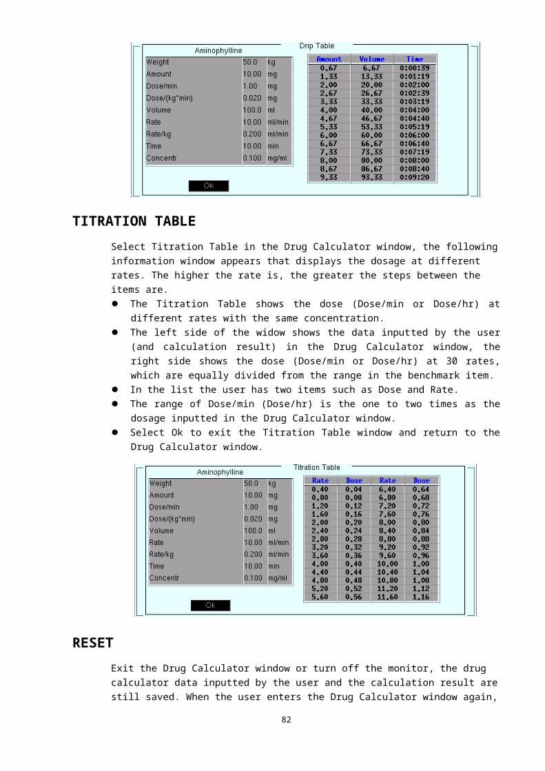
■ AVRG.Select this button, the following menu pops up.
The average period for heart rate (pulse rate) and ST segment calculation can be set in this menu.● BT.BT.: The average period is 1 heartbeat period.● 4 Beats: The average period is 4 heartbeat periods.● 8 Beats: The average period is 8 heartbeat periods.● 16 Beats: The average period is 16 heartbeat periods.
■ ST On/OffSelect this button, the Set ST Switch dialog box pops up, shown as the following:
● Auto: The monitor selects to display the ST segment or not automatically according to the ECG mode. In DIA mode, displays the ST segment, and in MON and OPR mode, hides ST segment.
● Always On: Always displays ST segment in the parameters area.● Always Off: Doesn’t display ST segment.
ST SEGMENTIn the default settings, the ST segment is always displayed. In MON or OPR mode, the ST numerics might be severely distorted. The variance of the ST segment at the waveform tracks can be measured and the result is displayed numerically in the parameters area. Measurement symbols of the ST segment: “+” means positive elevation, “-” means negative elevation.The ST segment is displayed as the following:
①Lower alarm limit of the main lead ST segment②Upper alarm limit of the main lead ST segment ③label of the main lead ST segment④Measured value of the main lead ST segment ⑤measured values of other lead ST segmentsSelect the label of main lead ST segment, such as ST (II) displayed above, the following menu appears.
■ Alarm On/Off
83
②
①
④
⑤
③
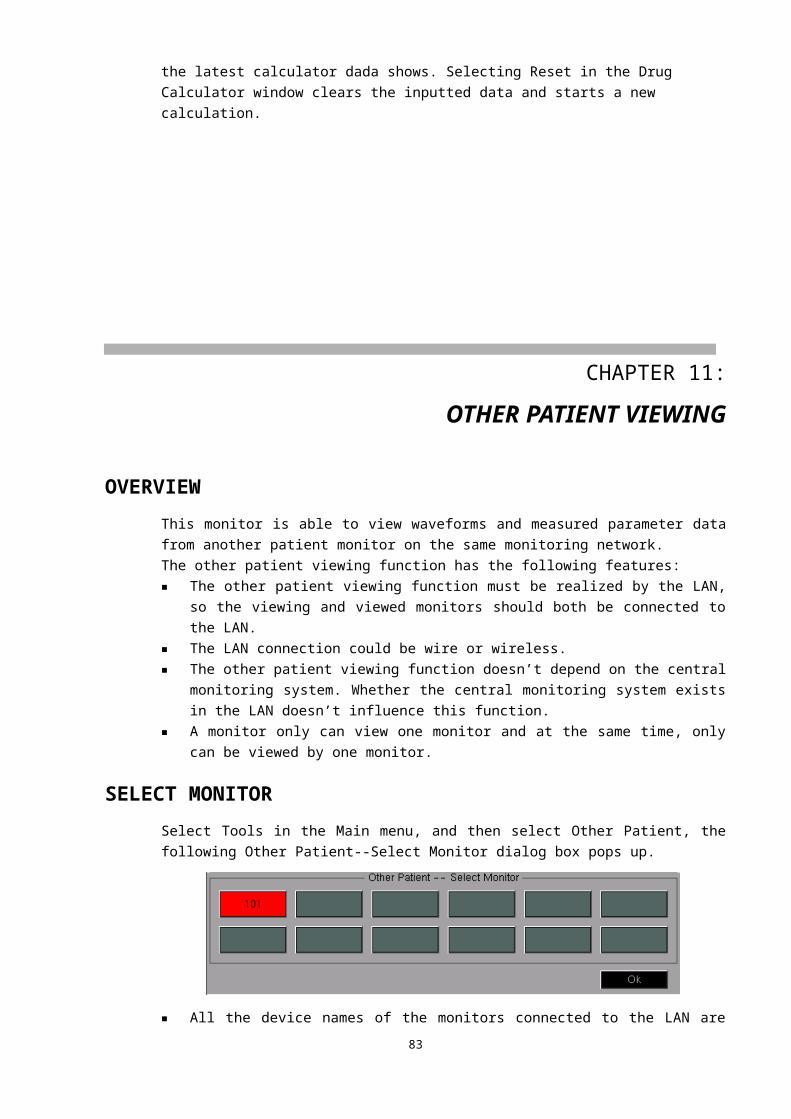
Enables or disables all the ST segment alarms.Alarms enabled: The ST segment alarms are turned on, the monitor alarms when the
measured ST segment value exceeds the preset alarm limit.Alarms disabled: Icon is displayed on the left side of the main lead ST segment label, the ST
segment alarms are turned off, and the monitor does not generate alarms when the measured ST segment value exceeds the preset alarm limit.
■ Alarm SettingSelect this button, the Set Alarm Limits dialog box pops up, shown as bellow.
The upper alarm limits, lower alarm limits, alarm switches and alarm printing switches of the ST segments can be set in this dialog box. See ALARM SETTINGS in CHAPTER 5 for detailed information.
MAINTENANCE AND CLEANINGThe exterior surfaces of the ECG cable may be cleaned with a soft cloth, dampened with the alcohol, and then be air-dried or dried with a clean dry cloth.
WARNING● If the ECG cable is damaged or aging, it shall be replaced by a new one.● Before cleaning the ECG cable, be sure to disconnect the monitor from the ECG cable, or
shut down the system and disconnect all power cords from the outlet.
TROUBLE SHOOTING
Problem Possible reasons Suggestions and way out
Lead offThe ECG electrode has fallen off from the patient or from the Monitor.
Ensure the electrode, lead and cable are properly connected.
ECG signal noise is too loud
The mode is not correctly set according to the environment.The power frequency is not set in accordance with the local power frequency.The Monitor is bad grounding.The electrode is badly connected to
Change the mode.
Set the power frequency properly. Refer to REGION SETTINGS in CHAPTER 4 for detailed information.Check the grounding system of the Monitor.Keep the patient quiet, and guarantee the
84
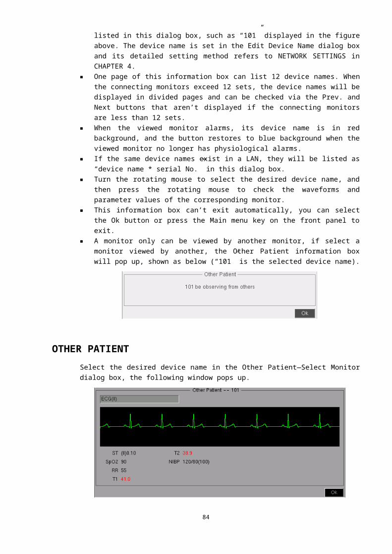
the patient. reliable connection of the electrode.
No heart rate is displayed;No heartbeat beeps
The ECG signal is very weak. (<0.25mV)The electrode is badly connected to the patient.The patient type is not correctly set.The gain is not enough.
Check the connection between the electrode and patient, ensure the reliable touch of the electrode and patient’s skin.
Correctly set the patient type.If it is in the MANUAL mode, please turn the gain to a right magnification.
CHAPTER 13: RESP MONITORING
OVERVIEWThis Monitor measures out the respiration movement waveform by the ECG cable with the impedance method. This respiration movement waveform is used to calculate the respiration rate and analyse the respiration status.The Monitor can measure three lead respiratory waveforms such as I, II or III lead, of which, the II lead is generally used. Because of the different signal strength, the Monitor provides AUTO and MANUAL modes to adjust the gain. The respiratory waveform will be clear and without distortion if an appropriate gain is adopted.
ELECTRODE PLACEMENTThe impedance respiration method of this Monitor is to monitor the patient’s respiration by the impedance variation between the two electrocardiogram electrodes of I, II or III lead. Since the same electrodes are used for ECG and RESP monitoring, the electrode placement is very important. Some patients, due to their clinical condition, expand their chest laterally, causing a negative intrathoracic pressure. In these cases it is better to place the two electrodes used for RESP monitoring laterally in the right axillary and left lateral chest areas, at the maximum point of the breathing movement, to optimize the respiratory waveform.
NOTE● RESP monitoring is not recommended on very active patients, because it will cause false
alarms.● Place the red and white electrodes diagonally to optimize the respiration waveform.● Try to avoid placing the electrodes so the liver area and the ventricles of the heart are in
path between the electrodes used for respiration, to avoid cardiac artifact to overlay on the ECG. This is particularly important when monitoring neonate patients.
85
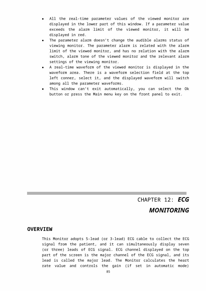
The electrode placement procedure refers to PREPARATION in CHAPTER 12.
MONITORING INTERFACEThe RESP monitoring displays a RESP waveform in channels area and the measured respiration rate value in parameters area.
RESP CHANNEL
Principal of impedance respiration monitoring
The movement of the thorax in the moment of the respiration will cause the
variation of the human body’s impedance, the range of the variation is about 0.1~3Ω,
G3 Monitor immits the human body a safe electric current which is 0.5~5mA by using
two electrode of the ECG lead with the 20KⅡ ~100KΩHZ carrier frequency sinusoidal
constant current, and then mesures out the difference of respiration impendace from electrode LL—RA . This difference of the respiration impedance shows the dynamic waveform of respiration
Using the impedance respiration method, G3 Monitor can measure out the human body respiration movement waveform by using the electrocardiogram lead line, and this respiration movement waveform can be used to the calculation of the human body respiration rate and the analyse of the human body respiration status.
The G3 Monitor measure three lead respiration waveforms according to the selection such as I, II, III, the II lead is generally used. Because of the different signal strength, the Monitor provides two kinds of gain adjustment functions : automatic adjustment and manual adjustment, it can make the respiration waveform clear and without distortion by adopting appropriate gain.
86
White (red)
Red (green)
White (red)
Red (green)
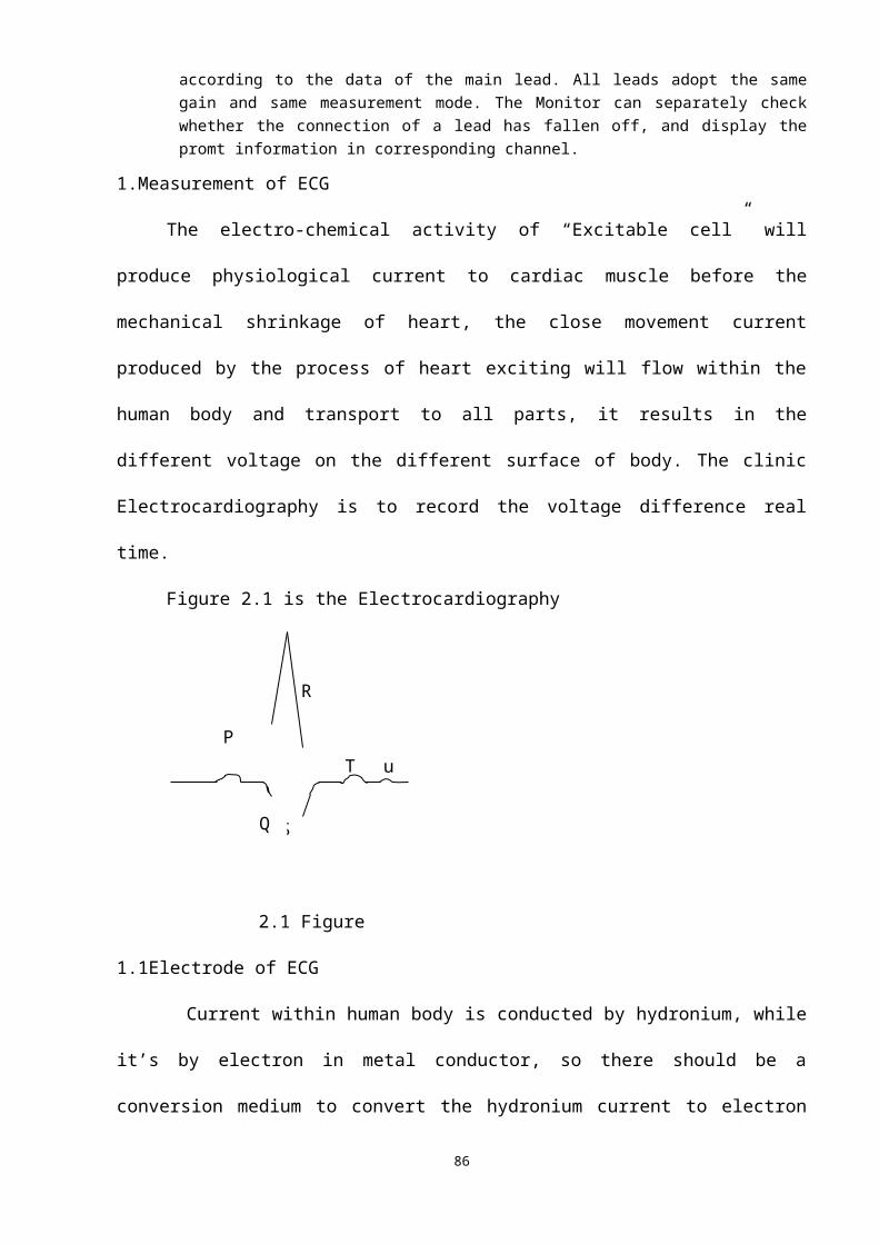
The electrode connection
The impedance respiration method of this Monitor is to monitor the patient’s respiration by the impedance variation between the two electrocardiogram electrodes. The respiration monitoring is realized via the electrocardiogram I, II or III lead and their corresponding electrodes, so no additional electrodes are required, and the installation of the electrode is very important. For some patient, because of their clinical situation, the horizontal expansion of the thoracic cage leads to the negativity thoracic cage internal pressure, under this situation, it is better to put the two respiration electrodes at the central line of the right armpit or the most active area on the left side of the thoracic cage when breathing, so that the optimum respiration wave is gained.
We suggest installing five lead electrodes for the respiration monitoring, as shown in Figure 3.4
Notice
①The respiration monitoring is not recommended to be used on the patient who will move or be moved a lot, because it will lead to mis-alarm.
In order to obtain optimum respiration wave, the white and the red② electrodes shall be installled catercorner. Avoid putting the liver and the ventricle on connecting line, which can avoid the false difference produced by the heart coverage or pulsation blood flow, this is very important in the using for neonate.
RESP channel is shown as the figure below:
① RESP channel label. Select this label, the menu as the following figure shows pops up.② Lead type: I, II or III.③ Gain mode: AUTO or MANUAL.④ Gain: Four grades are available: ×1/2, ×1, ×2 and ×4. If the gain is too great, the top
part of the waveform may be displayed as a straight line.⑤ Status prompt bar.⑥ Waveform speed. Four grades are available: 6.25mm/s, 12.5mm/s, 25mm/s
and 50mm/s.⑦ RESP waveform.
87
① ② ③ ④ ⑤ ⑥
⑦
⑧
⑨
⑧ Scale.⑨ Scale range. The unit is Ohm, and the length and range are different from time to time along
with different gains.
Select the RESP channel label, the following RESP menu appears:
■ RESP mode: Select this button, the channel switches to T-RESP channel.■ Gain Mode: Select this button, the gain mode switches between AUTO and MANUAL modes.■ Adjust Gain: This button is available only in manual mode. Select this button then turn the
rotating mouse to adjust the gain. Four grades are available: ×1/2, ×1, ×2 and ×4. Press the mouse to exit the gain adjustment, and the RESP waveform will be displayed in chosen gain.
■ Lead: Select this button, the waveform switches among the waveforms of I, II and III leads.■ Waveform Speed: Select this button, the waveform speed switches among 6.25mm/s, 12.5mm/s,
25mm/s and 50mm/s. Decrease it, the waveform is compressed, and you will see longer time quantum; increase it, the waveform is expanded, and you will get more detailed view.The Waveform Speed button in the Display menu also can be used to change the RESP waveform speed. No matter which method is used, it will change both the waveform speed of the RESP and T-RESP simultaneously.
RESPIRATION RATEThe respiration rate is displayed in the parameters area, shown as below:
① Lower alarm limit. The monitor generates alarms when the measured respiration rate value is less than it.
② Upper alarm limit. The monitor generates alarms when the measured respiration rate value is greater than it.
③ Respiration rate label. Select this label, the following menu appears.④ Measured respiration rate value.
Select the respiration rate label (RR), the following menu pops up:
■ Alarm On/Off: Enables or disables the RR alarm.Alarms enabled: The RR alarm is turned on and the monitor alarms when the measured
RR value exceeds the preset alarm limit.Alarms disabled: Icon is displayed on the left side of the RR label, the RR alarm is turned
off, and the monitor does not generate alarms when the measured RR value exceeds the preset alarm limit.
■ Alarm Setting: Select this button, the following Set Alarm Limits dialog box pops up.
88
①②
③
④
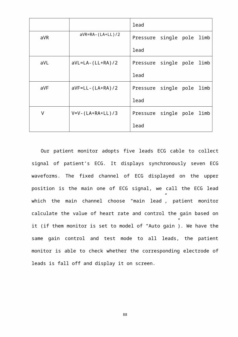
The upper alarm limit, lower alarm limit, alarm switch and alarm printing switch of RR can be set in this dialog box. See ALARM SETTINGS in CHAPTER 5 for detailed information.
■ RR Source: Select this button, the following menu pops up.
The respiration rate source can be viewed and selected in this menu. There are four options: Auto, RESP, T-RESP and CO2. The monitor will display the RR value calculated from the chosen source. If it is set as Auto, the RR source is in accordance with the current channel, which is RESP when RESP channel is displayed or T-RESP when T-RESP channel is displayed.
PROMPT MESSAGESIn the status prompt bar of the RESP channel, the current respiration status message is displayed at the position ⑤.Lead Off: The current lead is not properly connected. When the lead is not inserted on the Monitor
or connected to the patient, this message shows.Running: Except the abovementioned condition, the system prompts “Running”.
CHAPTER 14: T-RESP MONITORING
T-RESP CHANNEL
Principal of the nasal tube respiration monitoringThe respiration will cause the flow of the air in the nasal tube, this flow cause the variation of the
thermistance’s value. By obtaining this variation, the nasal tube respiration monitoring works.
T-RESP monitoring is the nasal tube respiration monitoring. In the default settings, the RESP channel is displayed, and it can be switched to the following T-RESP channel via RESP mode button in the RESP menu.
89
① ② ③
④
① T-RESP channel label. Select this label, the T-RESP menu pops up.② Status prompt message. Always shows “Running”.③ Waveform speed. Four grades are available: 6.25mm/s, 12.5mm/s, 25mm/s and 50mm/s.④ T-RESP waveform.
T-RESP MENUSelect the T-RESP channel label, the following menu appears:
■ RESP mode: Select this button, the channel switches to RESP channel.■ Waveform Speed: Select this button, the waveform speed switches among 6.25mm/s, 12.5mm/s,
25mm/s and 50mm/s.The Waveform Speed button in the Display menu also can be used to change the T-RESP waveform speed. No matter which method is used, it will change both the waveform speed of the RESP and T-RESP simultaneously.
NOTE● The T-RESP respiration rate is displayed at the same positon of the RESP respiration
rate. To display it, you can set the RR Source as T-RESP or Auto. Detailed information refers to RESPIRATION RATE in CHAPTER 13.
MAINTENANCE AND CLEANINGIn case of an exception in the sampling system, check for entanglement of the tube. If the tube is not entangled, the tube has been blocked, you should replace it with a new one.
WARNING● The nasal tube is disposable, must not re-sterilize or reuse it.● Do not press or limit the nasal tube.● The nasal tube should be recycled or disposed of, complying with the local laws.
CHAPTER 15: NIBP MONITORING
OVERVIEWThe non-invasive blood pressure (NIBP) module measures blood pressure using the oscillometric method. This monitor can be applied to adult, pediatric and neonate patients. Three measurements are available: manual, auto and continuous. Each mode displays the systolic pressure (SYS), mean arterial pressure (MAP) and diastolic pressure (DIA). ■ Manual: Pressing the NIBP key on the front panel starts a NIBP measurement.■ Auto: The NIBP measurement is conducted automatically at a preset interval.
90
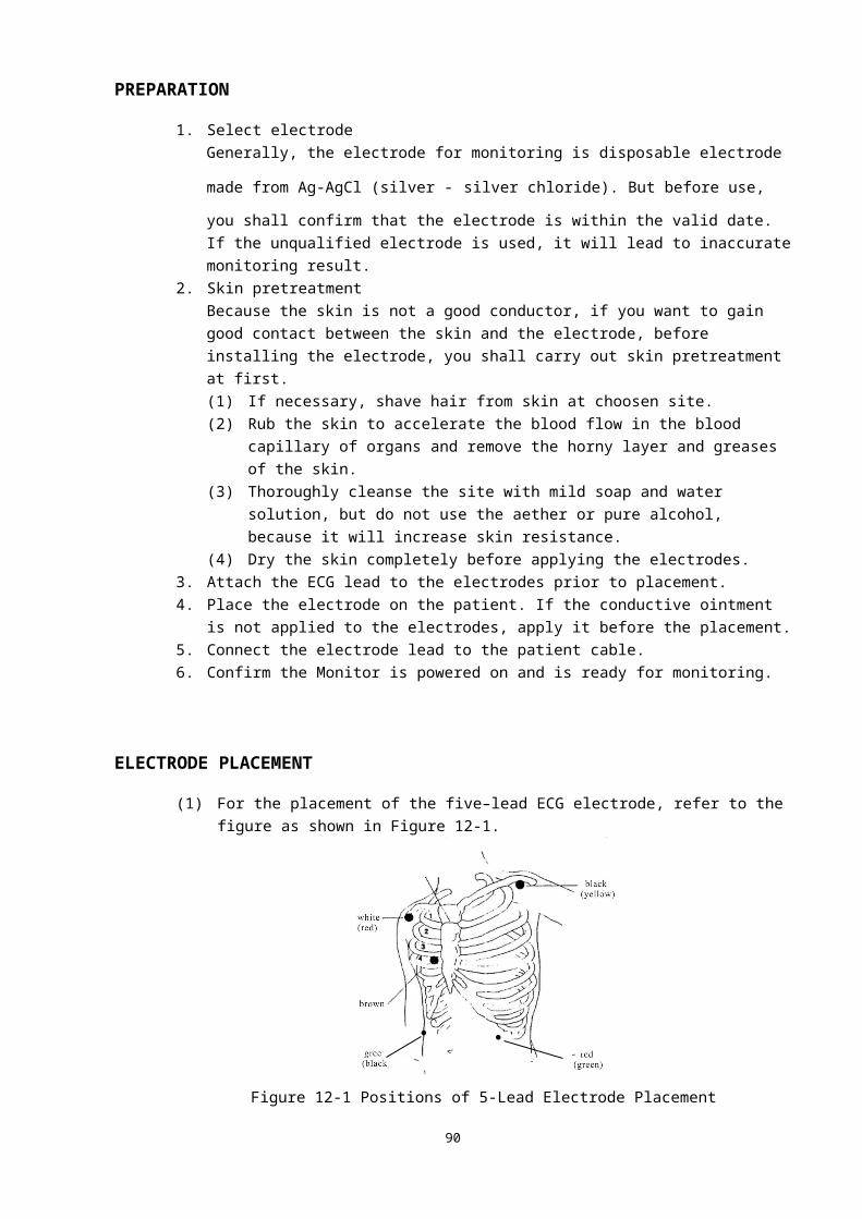
■ Continuous: The NIBP measurement is performed as many times as possible in five minutes.
Blood Pressure Measurement Principle
NIBP measurement adopts vibration method. The principle is to charge air to blood pressure cuff to the degree that arteries are pressed completely and the blood flowing is blocked. And while the cuff is deflated gradually, the arteries are in the process of utter blocking, gradual loosing and unobstructing. In this process the artery pressure pulsation will generate air oscillating waves in the cuff. Theoretic arithmetic and experiments indicates that oscillating waves have defined correspondence with artery systolic blood pressure, mean blood pressure, and diastolic blood pressure. Hence systolic blood pressure, mean blood pressure, and diastolic blood pressure can be measured by analyzing measurement results and pressure oscillating waves in the cuff.
When the blood pressure measurement process starts up, the Monitor charges the air into the blood pressure cuff, the human body blood pressure, including the systolic blood pressure, diastolic blood pressure and mean pressure are measured out via the sensors, a measurement process is about 40 seconds.
There are three start-up methods for blood pressure measurement, one is manual measurement mode, the other is automatic measurement mode, and the third is consecutive measurement mode.
mmHg 200 165mmHg
2.0 cuff pressure 100
1.0 PS Outline of pulse
Pulse oscillation waveform
Notices of
NIBP
Measurement 1. Korotkoff Sound Method, widely-adopted in clinics, is similar to vibration method. But there are many coherent defects in Korotkoff Sound Method. It primarily relies on the coordination between man’s vision and hearing, thus the method is rather subjective and unduplicated. Therefore the results by Korotkoff Sound Method can not be applied to evaluate the results by vibration method.
2. Human arterial blood pressure is a changeable physiological parameter, related 91
00
Time
袖带压
Puls
e w
avef
orm
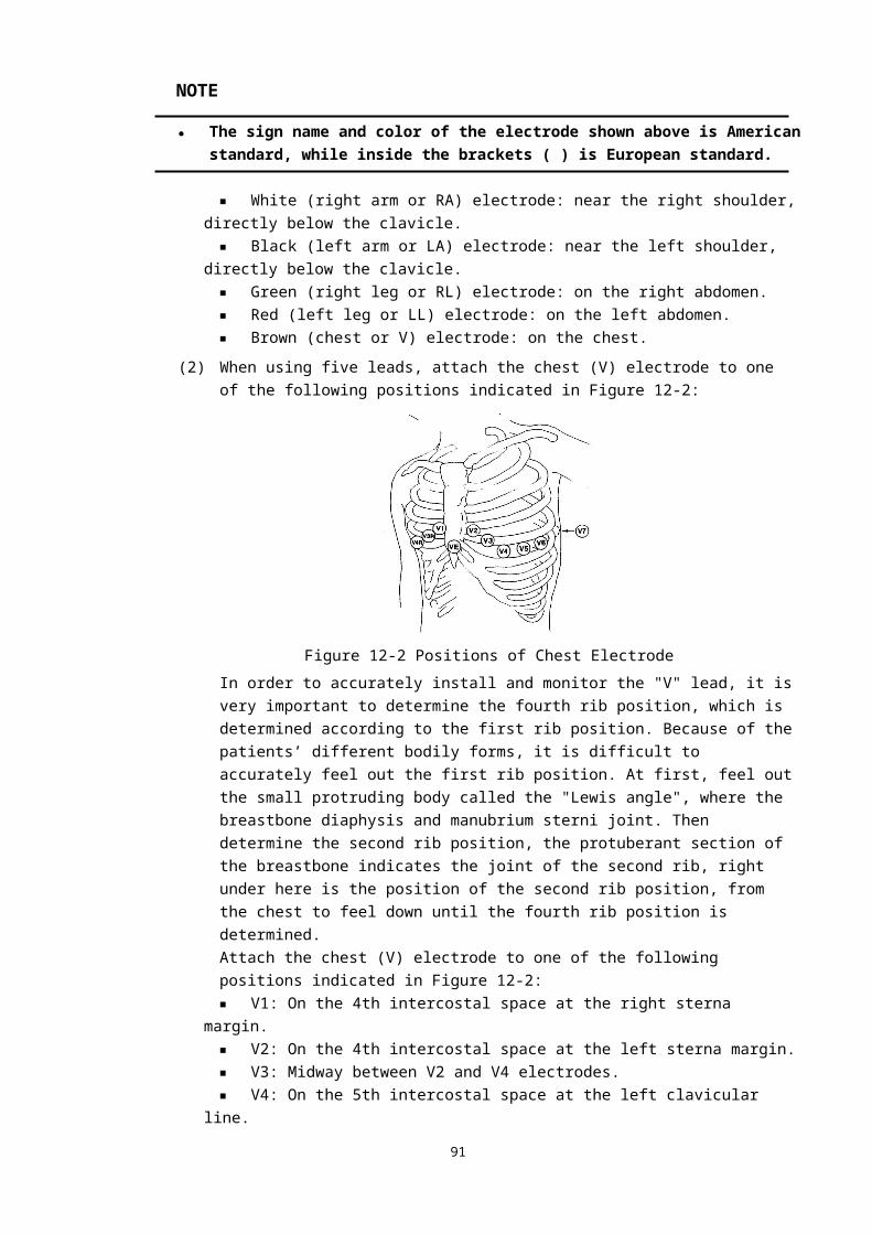
with the patient’s emotion, psychological change, posture and position during the measurement. So it should be considered in measurement and evaluation.
3. The vibration measurement bases on the oscillating waves in cuff, so the oscillation from the outside and the movement of the patient’s arm will affect the measurement results. The serious consequence is the failure in the measurement. It needs measuring again.
The noninvasive blood pressure (NIBP) measurement adopts the succussion;
It is applicable to adult, pediatric and neonate.
The measurement mode: manual, automatic and consecutive. Each mode displays systolic blood pressure, mean pressure and diastolic blood pressure.
MONITORING PROCEDURETo perform NIBP measurement on a patient, follow the procedure as below:1. Power on the monitor.2. Check the patient type. If the patient type is incorrect, select a correct
patient type in Patient Information dialog box.3. Plug the air hose in the NIBP cuff connector of the monitor.4. Apply a cuff of proper size to the upper arm or the leg of the patient.5. Connect the cuff with the air hose.6. Press the NIBP key on the front panel to start the NIBP measurement.
CUFF SELECTION AND PLACEMENT
1. Identify the patient limb circumference.2. Select appropriate cuff; limb circumference is identified on each cuff.3. Verify the cuff is completely deflated; place cuff around extremity being
used and make sure the marking φ matches artery location.4. Verify the cuff is not wrapped too tightly around the limb. Excessive
tightness may cause discoloration or ischemia of the extremities.5. Make sure that the cuff edge falls within the range of the <-> mark. If it
does not, use a larger or smaller cuff that will fit better.
NOTE
92

● The width of the cuff should be either 40% of the limb circumference (50% for neonates) or 2/3 of the upper arm length. The inflatable part of the cuff should be long enough to circle 50-80% of the limb. The wrong size cuff can cause erroneous readings. If the cuff size is in question, use a larger cuff.
● The limb chosen for taking the measurement should be placed at the same level as the patient's heart. If this is not possible, use the following method to correct the measurement result: If the cuff is placed higher than the heart level, add 0.75mmHg
(0.10 kPa) for each centimeter of difference, or 1.9mmHg (0.25kPa) for each inch of difference.
If it is placed lower than the heart level, deduct 0.75 mmHg (0.10 kPa) for each centimeter of difference, or 1.9mmHg (0.25kPa) for each inch of difference.
● If you are in doubt about the accuracy of any reading(s), check the patient's vital signs by an alternative method before checking the function of the monitor.
WARNING● Use only the specified accessories for monitoring, or it will lead to the malfunction of the
Monitor.● You must not perform NIBP measurements on patients with sickle-cell disease or under
any condition where the skin is damaged or expected to be damaged.● For a thrombasthemia patient, it is important to determine whether measurement of the
blood pressure shall be done automatically.● Ensure that the setting is correctly made when performing measurements on children.
Incorrect patient type setting may cause a danger to the patient because adult blood pressure level is higher than children.
● Before the measurement, you shall confirm your configuration is suitable to the patient (adult, pediatric or neonate).
● Do not apply the cuff to a limb that has an intravenous infusion or catheter in place. This could cause tissue damage around the catheter when infusion is slowed or blocked during cuff inflation.
● Auto non-invasive blood pressure measurements performed in long intervals may incur ischemia and neuropathy in the limb wearing the cuff. When monitoring a patient, examine the extremities of the limb frequently for normal color, warmth and sensitivity. If any abnormality is observed, change the position of the cuff on the patient or stop the blood pressure measurements immediately.
● Make sure the air tubing connecting the blood pressure monitor is not blocked, twisted, or tangled.
93
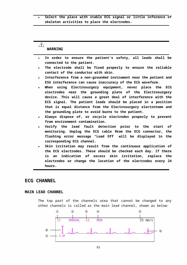
MEASUREMENT LIMITATIONSNon-invasive blood pressure measurement uses the oscillometric method of measurement. The monitor detects the regular arterial pressure pulse. In some circumstances when the patient's condition makes it difficult to detect this pulse, the measurement becomes unreliable and the measurement time increases. You should be aware that the following conditions could interfere with the measurement, make the measurement unreliable, prolong the measurement, or even make a measurement impossible.■ Patient movement: E.g.The patient is moving, shivering or jerking.■ Cardiac arrhythmia: E.g.The patient's cardiac arrhythmia has caused an
irregular heartbeat.■ Heart-lung machine: E.g. Measurements will be impossible if the patient is
connected to a heart-lung machine.■ Pressure changes: E.g.The patient's blood pressure is changing rapidly over the
period of time during which the arterial pressure pulses are being analyzed to obtain the measurement.
■ Severe shock: E.g.If the patient is in severe shock or hypothermia, reduced blood flow to the peripheries will cause reduced pulsation of the arteries.
■ Heart rate extremes: The monitor is unable to perform pressure measurements at a heart rate of less than 15 bpm and greater than 300 bpm.
MONITORING INTERFACE
The NIBP measurement does not produce any waveform. Instead, it displays the measurement result in the parameters area as shown below.
① Alarm limit of the diastolic pressure. When the measured diastolic pressure value exceeds this limit, the monitor generates alarms.
② Alarm limit of the systolic pressure. When the measured systolic pressure value exceeds this limit, the monitor generates alarms.
③ NIBP alarm off icon. When the alarms for systolic pressure, diastolic pressure and mean arterial pressure are disabled, this icon is displayed, if one of them is enabled, this icon will disappear.
④ NIBP label. Select this label to access the NIBP menu.⑤ NIBP unit: mmHg or kPa. Refer to REGION SETTINGS in CHAPTER 4 for setting
method.⑥ Measured systolic pressure and diastolic pressure values. The left side of “/” is systolic
94
①
②
③ ④ ⑤
⑥
⑦
⑧⑨
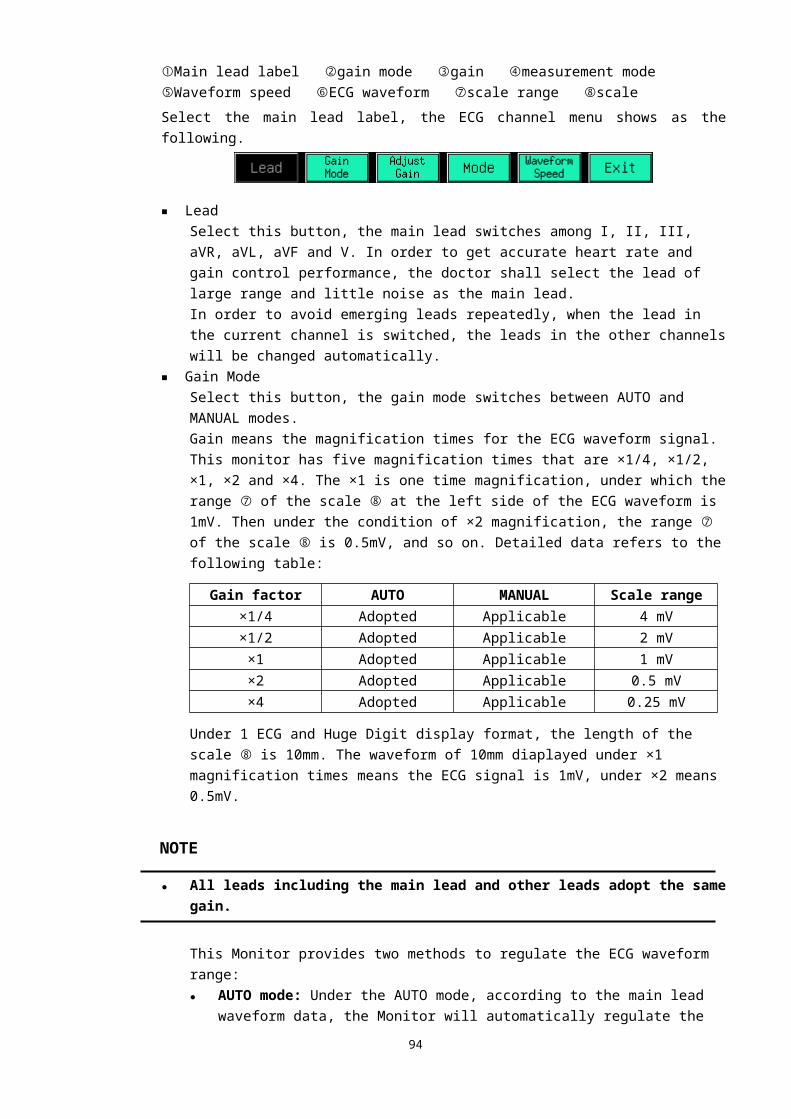
pressure value, while the right side is diastolic pressure value.⑦ Measured mean arterial pressure value.⑧⑨Information prompt bar. Different information is displayed on it for different situations.
Selecting the NIBP label pops up the following NIBP menu:
■ Alarm On/Off: Enables or disables the alarms for SYS, DIA and MAP simultaneously.Alarms enabled: The NIBP alarm is turned on and the monitor alarms when the
measured NIBP value exceeds the preset alarm limit.Alarms disabled: Icon is displayed on the left side of the NIBP label, the NIBP alarm is
turned off, and the monitor does not generate alarms when the measured NIBP value exceeds the preset alarm limit.
■ Alarm Setting: Select this button, the following Set Alarm Limits dialog box pops up.
The upper alarm limits, lower alarm limits, alarm switches and alarm printing switches for SYS, DIA and MAP can be set in this dialog box. See ALARM SETTINGS in CHAPTER 5 for detailed information.
■ Auto Manual: Switches between the auto and manual modes. In manual mode, word MANUAL is displayed at position ⑨; while in auto mode, word AUTO is displayed at positon ⑨ with the clock format time at position ⑧.
■ Test Interval: Selecting this button in auto mode accesses the following Set NIBP Auto Test Interval dialog box.
In this dialog box, the NIBP automatic measurement interval time, which is set as 5 minutes in default settings, can be set in the range from 2 minutes to 8 hours and displayed in the information prompt bar.
■ Venous Puncture: Sets the venipuncture. ■ Stat Test: Selecting this button starts a continuous measurement for five minutes.■ Inflate Pressure: Selecting this button in manual mode accesses the following dialog box.
The max cuff pressure can be set in this dialog. The default max cuff pressure is 165mmHg for adult, 145mmHg for pediatric and 125mmHg for neonate.
95
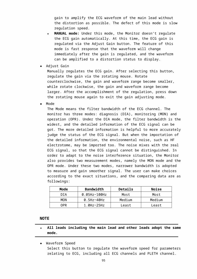
FUNCTIONSThe NIBP monitoring has two functions, one is NIBP measurement, and the other is the venipuncture function.
NIBP MEASUREMENTWhen the NIBP measurement starts, the Monitor inflates the air into the cuff, and the SYS, DIA and MAP are measured out via the sensor. A measurement process lasts about 40 seconds.There are three NIBP measurement modes, one is manual mode, the other is auto mode, and the third is continuous mode.
Manual modeSelect the Auto Manual button in the NIBP menu, if word MANUAL is displayed at the position ⑨, the manual mode is selected. In this mode, a NIBP measurement shall be started manually by pressing the NIBP key on the front panel. Before manual NIBP measurement, the max cuff pressure should be set to a proper value.
Auto modeSelect the Auto Manual button in the NIBP menu, if word AUTO is displayed at the position ⑨, the auto mode is selected. In this mode, the monitor periodically starts the NIBP measurement automatically at the preset time interval.The auto mode has two statuses, one is the stay status. In this status, the clock at position ⑧ stays, and the auto measurement has not been started yet. The other status is the running status. In this status, the clock at position ⑧ runs, and the auto measurement has been started. The clock at position ⑧ indicates how much time still remains for the next measurement.In the stay status, press the NIBP key to start the auto measurement. At this time, the clock at position ⑧ begins to run. Switching to the manual mode, then switching back to the auto mode can stop the auto measurement. Pressing the NIBP key during the NIBP measurement can stop the measurement and switch the running status to stay status.
Continuous modeSelecting the Stat Test button in the NIBP menu starts a continuous measurement which is provided for surgical or emergent patient. Its feature is that it continuously measures NIBP for five minutes once it is started, and the measurement mode adopted is simpler than other modes. After five minutes, the monitor restores to the status (auto or manual) before the continuous measurement.
NOTE● Whether in the auto or manual mode, pressing the NIBP key on the front panel will start
a NIBP measurement.● Pressing the NIBP key during the NIBP measurement stops the ongoing measurement and
deflates the cuff.
96
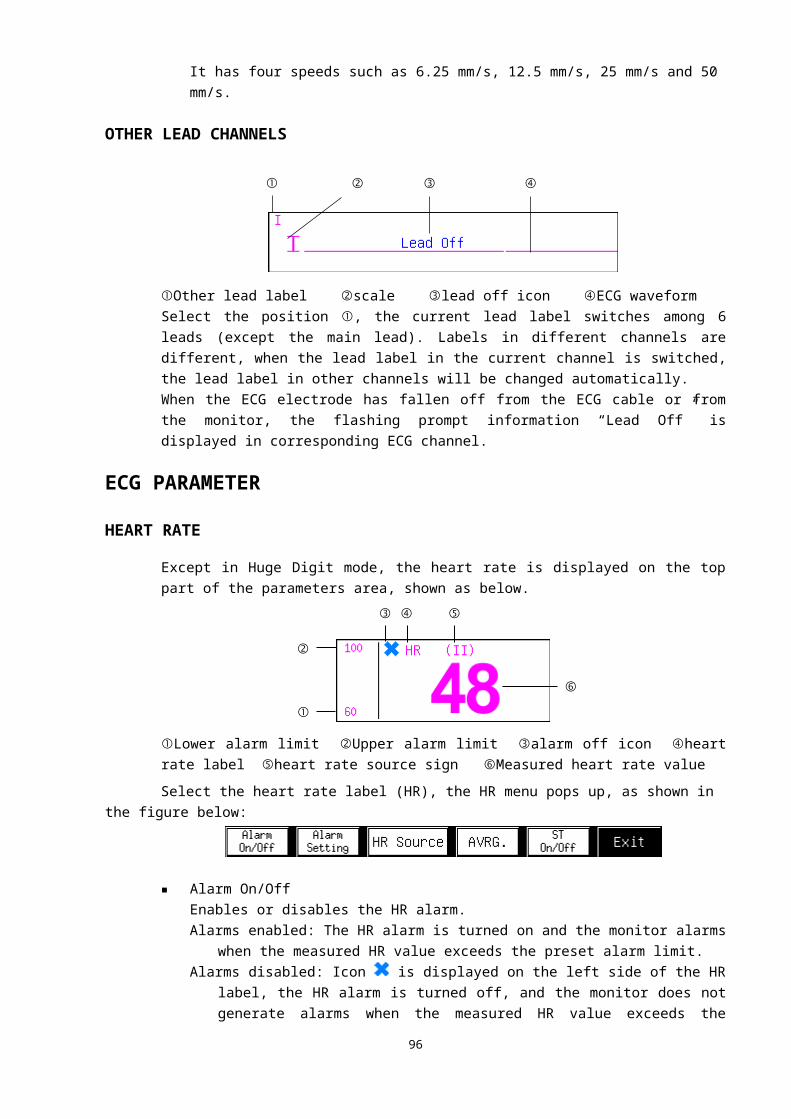
VENIPUNCTUREUnder the venipuncture mode, the monitor inflates the air into the cuff to a preset pressure, and keeps the pressure during the preset time, then deflates.Select the Venous Puncture button in the NIBP menu, the following dialog box pops up.
① Venipuncture switch: Enables or disables the venipuncture.Open: The venipuncture is turned on, the word VENOUS and the preset preasure are displayed
in the information prompt bar, shown as the figure below.Close: The venipuncture is disabled.
② Keeping pressure: The air inflating pressure.③ Keeping time: From the air inflating time, until the air is deflated.
Patient type Pressure setting range Default pressure Maximum keeping timeAdult 20-120 mmHg 60 mmHg 170 s
Pediatric 20-80 mmHg 40 mmHg 170 sNeonate 20-50 mmHg 30 mmHg 85 s
④ Select this key to confirm the setting.
Under the venipuncture mode, press the NIBP key to start and stop the air inflating.
MAINTENANCE AND CLEANING
Reusable blood pressure cuffsThe cuff is not suitable for dry-cleaned. Instead, it should be machine or hand washed. Hand washing, may prolong the service life of the cuff. Before washing, remove the latex rubber bladder. Allow the cuff to dry thoroughly after washing, and then reinsert the rubber bladder. The cuff can be disinfected by means of conventional autoclaving, gas, or radiation disinfection in hot air ovens, or sterilized by immersion in decontamination solutions. Remember to remove the rubber bladder if you use this method.
97
① ② ③
④

To replace the rubber bladder in the cuff:1. Place the bladder on top of the cuff so the rubber tubes line up with the
large opening on the long side of the cuff.2. Roll the bladder lengthwise and insert it into the opening on the long side of
the cuff.3. Hold the tubes and the cuff and shake the complete cuff until the bladder is
in position.4. Thread the rubber tubes from inside the cuff, and out through the small
hole under the internal flap.Disposable blood pressure cuffs
Disposable cuffs are intended for single patient use only. Do not sterilize or use autoclave sterilization for disposable cuffs. But they can be washed with a mild soap and water solution to control the infection.
NOTE● Disposable blood pressure cuffs must be recycled or disposed of properly, complying with
the local laws.
WARNING● Do not press or limit the rubber tube on the cuff.● Do not allow the water or detergent liquid get inside the NIBP connection, otherwise the
monitor may be damaged.● When a reusable cuff is not connected to the monitor or is being cleaned, avoid splashing
liquid into the rubber tube or the monitor inadvertently.● When cleaning the Monitor, only clean the connector external part, and do not clean its
internal part.
TROUBLE SHOOTINGThe NIBP current status is displayed at the positon ⑨, please adopt the following disposals if the messages shown as below appear.
Problems Possible reasons Suggestions and way out
98
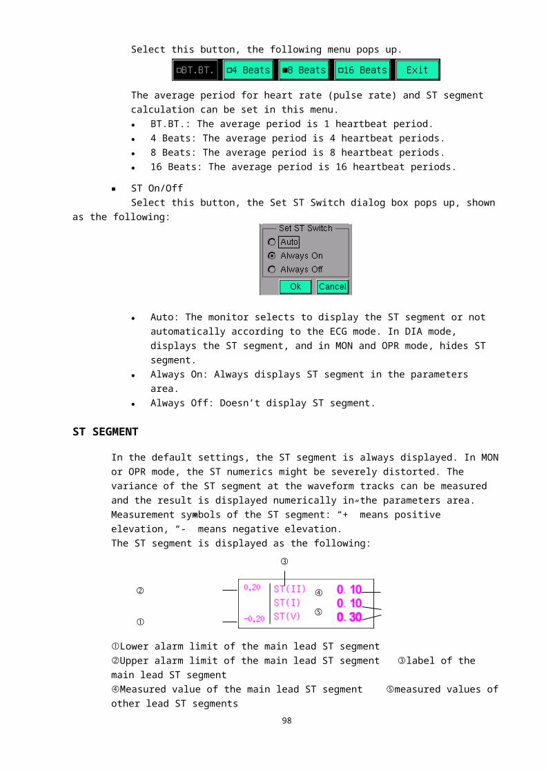
Startup Fail Monitor hardware errorStop the NIBP measurement, and inform the qualified maintenance personnel specified by the supplier to repair.
No Cuff The cuff is not properly tied up or no cuff
Tie up the cuff
Cuff LeakThe cuff, rubber tube or connector is damaged
Check and replace the air leakage part, if necessary, inform the qualified maintenance personnel specified by the supplier to repair.
Pulse too weakThe cuff is too loose or the patient’s pulse is too weak.
Use other method to measure the NIBP.
Over Pressure The pressure exceeds the specified safety upper limit
Remeasure it, if the failure continues, stop the NIBP measurement, and inform the qualified maintenance personnel specified by the supplier to repair.
NIBP Compensate
1. Press the menu key and enter the system setup item
2. Press the system setup menu key and enter the maintenance
setup item
3. Press the function maintenance menu key and enter the
Reserved 1
4. Input the password 1231 and enter the function compensate menu item ,you will do
it for Temperature 、NIBP and SPO2
99

The service man compensate the function such as Temperature 、NIBP and
SPO2,and so on. according to the monitoring the parameter result so as to measuring the real result,the other function parameter is the same as to the NIBP
The NIBP compensate range is from 75% to 125%,which is some times
than measuring data.The detailed compensate windows of SYS\DIA\Map as follows:
100
CHAPTER 16: TEMP MONITORING
TEMPERATURE PROBE INSTALLATIONThe monitor is able to use two temperature probes simultaneously. Attach the temperature probe to the patient’s body where ought to be measured, to abtain two temperature values and the difference between them.If a disposable temperature probe is used, plug the temperature probe cable in the temperature probe connector, and then connect the temperature probe with the cable; if a reusable temperature probe is used, connect the temperature probe with the temperature probe connector directly.
NOTE● The disposable temperature probe is for single patient use only.
WARNING● Be careful to avoid damaging the temperature probe and cable. When the temperature
probe and cable are not in use, shape them into a loose round. If the cable is tangled too tightly or over-bent, mechanical damage may occur.
● The calibration of the temperature measurement function is desired every year (or as dictated by your Hospital Procedures Policy). If you need to calibrate the temperature measurement function, contact the manufacturer.
TEMP PARAMETERThe temperature measurement result is displayed in the parameters area, as shown in the figure below:
101
③ ④ ⑤
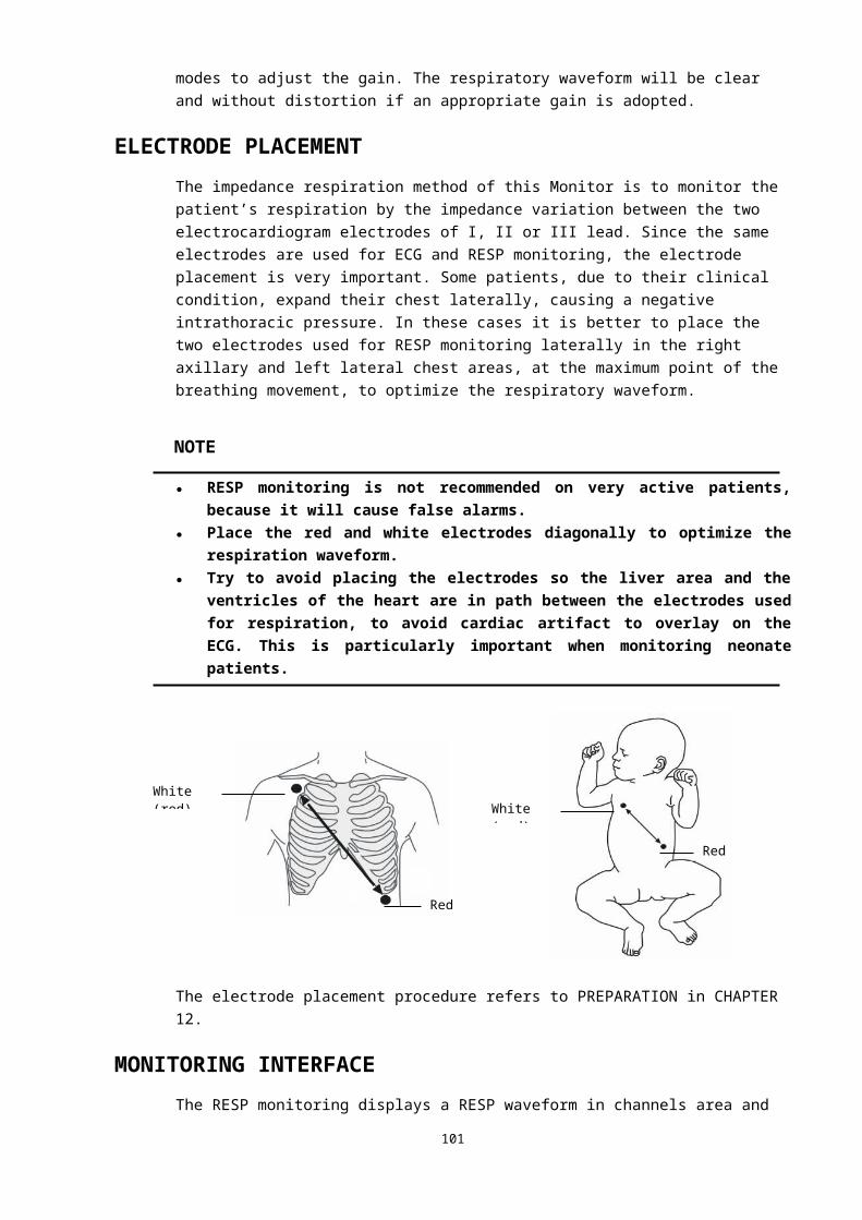
① Temperature lower alarm limit. When the measured temperature value is less than it, the monitor generates alams.
② Temperature upper alarm limit. When the measured temperature value is greater than it, the monitor generates alams.
③ Temperature alarm off icon. When the temperature alarm is disabled, it is displayed.④ Temperature label: Select this label, and the menu shown as below pops up.⑤ Temperature unit: ℃ or ℉. See REGION SETTINGS in CHAPTER 4 for the setting method.⑥ Temperature difference: It is the absolute value of the difference between the temperature
values of two channels.⑦ Measured temperature value of channel 1: Measurement range: (25.0-45.0)℃.⑧ Measured temperature value of channel 2: Measurement range: (25.0-45.0)℃.
TEMP MENUSelecting the temperature label in the parameters area pops up the following menu.
■ Alarm On/Off: Enables or disables the TEMP alarm.Alarms enabled: The TEMP alarm is turned on and the monitor alarms when the
measured TEMP value exceeds the preset alarm limit.Alarms disabled: Icon is displayed on the left side of the TEMP label, the TEMP alarm is
turned off, and the monitor does not generate alarms when the measured TEMP value exceeds the preset alarm limit.
■ Alarm Setting: Select this button, and the following Set Alarm Limits dialog box pops up.
The upper alarm limit, lower alarm limit, alarm switch and alarm printing switch of TEMP can be set in this dialog box. See ALARM SETTINGS in CHAPTER 5 for detailed information. The temperature difference has no alarm function.
■ Mode: Select this button, the TEMP display mode switches among three modes. One is displaying the temperatures of two channels and the temperature difference, another is displaying the temperatures of two channels, and the third is displaying the temeperature of channel 1 and the temperature difference. The mode can be selected according to the requirement, shown as below.
102
② ⑥
⑦
⑧①

MAINTENANCE AND CLEANING
WARNING● Before cleaning the monitor or the probe, make sure the monitor is turned off and
disconnected from AC power.
Reusable temperature probes
■ The temperature probe should not be heated to a temperature over 100℃ (212℉). It is only able to bear the temperature between 80 and 100℃ (176 to 212℉) for a short time.
■ The probe must not be disinfected in steam.■ Only detergents containing alcohol can be used for disinfection.■ The rectal probes should be used, if possible, in conjunction with a
protective rubber cover.■ To clean the probe, hold the tip with one hand and with the other hand rub
the probe down in the direction of the connector using a moist lint-free cloth.
NOTE● Disposable temperature probes must not be re-sterilized or reused.● Disposable temperature probes must be recycled or disposed of properly, complying with
the local laws.
Temperature Compensate
During the monitoring the patient Temperature parameter,you will compensate the
103
temperature if you find that the temperature departure some range of the real result as
follows:
1.Press the menu key and enter the system setup item
2.Press the system setup menu key and enter the maintenance
setup item
3.Press the function maintenance menu key and enter the
Reserved 1
4.Input the password 1231 and enter the function compensate menu item ,you will do it
for Temperature 、NIBP and SPO2
Temperature compensate range is from +1.5℃ to -1.5℃,Both T1
channel and T2 channel compensate windows as follows:
104

CHAPTER 17: SpO2
MONITORING
OVERVIEWSpO2 measurement is based on two principles: Firstly, oxyhemoglobin and deoxyhemoglobin differ in their absorption of red and infrared light. Secondly, the volume of arterial blood in tissue changes during the pulse. A monitor determines SpO2 (oxygen saturation) by passing red and infrared light into an arteriolar bed and measuring changes in light absorption during the pulsatile cycle. Red and infrared low-voltage light-emitting diodes (LEDs) in the sensor serve as light sources, a photodiode serves as the photo detector.Because oxyhemoglobin and deoxyhemoglobin differ in light absorption, the amount of red and infrared light absorbed by blood is related to hemoglobin
105
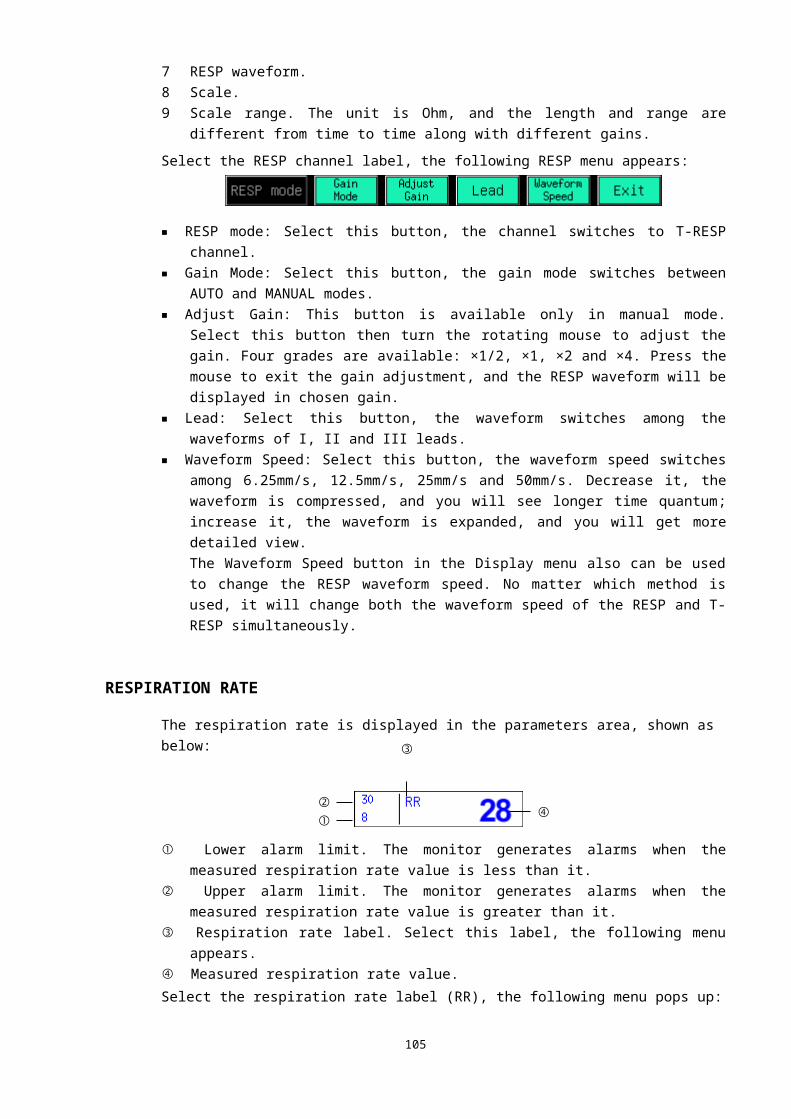
oxygen saturation. To identify the oxygen saturation of arterial hemoglobin, the monitor uses the pulsatile nature of arterial flow. During systole, a new pulse of arterial blood enters the vascular bed, and the blood volume and light absorption increase. During diastole, the blood volume and light absorption reach their lowest point. The monitor bases its SpO2 measurements on the difference between maximum and minimum absorption (i.e., measurements at systole and diastole). By doing so, it focuses on light absorption by pulsatile arterial blood, eliminating the effects of nonpulsatile absorbers such as tissue, bone, and venous blood.The monitor determines SpO2 and pulse rate by passing two wavelengths of light, one red and one infrared, through body tissue to a photodetector. During measurement, the signal strength resulting from each light source depends on the color and thickness of the body tissue, the probe placement, the intensity of the light sources, and the absorption of the arterial and venous blood (including the time varying effects of the pulse) in the body tissue (Refer to Figure 17-1).
The monitor processes these signals, separating the time invariant parameters (tissue thickness, skin color, light intensity, and venous blood) from the time variant parameters (arterial volume and SpO2) to identify the pulse rate and calculate oxygen saturation. Oxygen saturation calculations can be performed because oxygen saturated blood predictably absorbs less red light than oxygen depleted blood.The monitor can be used under low perfusion with same accuracy as normal condition.
The monitor measures the patient’s SpO2 and displays:■ Pulse rate (PR) value in the parameters area.■ PLETH waveform and pulse intensity (perfusion indicator) in the channels
area.■ Oxygen saturation (SpO2 %) value in the parameters area.As the following figure shows, the perfusion indicator (prorate with the pulse intensity) is located on the left side of the PLETH waveform while the measured SpO2 value on the right. The SpO2 value is displayed by percentage. Besides, the SpO2 label in the parameters area allows you to access the SpO2 menu.
106
MONITOR
DETECTOR
PERFUSION INDICATOR
FIGURE 17-1 SpO2 THETORY OF OPERATION
RED LED AND INFRARED LED LIGHT SOURCES
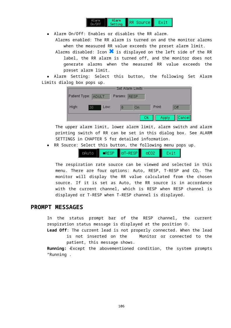
The PR value is displayed in the parameters area only if:1. SpO2 is selected in the HR Source menu; or2. Auto is selected in the HR Source menu and the received ECG signal is bad.
PRECAUTIONS
WARNING● The monitor can overestimate the SpO2 value in the presence of Hb-CO, Met-Hb or dye
dilution chemicals.● ES (Electrosurgery) equipment wire and SpO2 cable must not be tangled up. Carefully
route patient cabling to reduce the possibility of patient entanglement or strangulation.● Do not use this instrument and the sensors during magnetic resonance imaging (MRI).
Induced current could potentially cause burns. The monitor may affect the MRI image, and the MRI unit may affect the accuracy of the oximetry measurements.
● Do not put the SpO2 sensor on the limb with arterial catheter or venous syringe.● Do not perform SpO2 monitoring and NIBP measurements on the same arm
simultaneously. Obstruction of blood flow during NIBP measurements may adversely affect the reading of the SpO2 value.
● Before performing the testing, check the sensor cable. After unplugging the SpO2 sensor cable from the socket, the system shall display the flashing prompt information "Sensor Off" above the PLETH waveform.
● Prolonged and continuous monitoring may increase the risk of burns at the site of the sensor. It is especially important to check the sensor placement, and ensure proper attachment on neonates and patients of poor perfusion or skin sensitive to light. Check the sensor location every 2–3 hours and move to another location if the skin deteriorates. More frequent examinations may be required for different patients.
NOTE● Place the SpO2 sensor cable at the backside of the patient hand. Make sure the fingernail
is just opposite to the light emitted from the sensor.
MONITORING PROCEDUREFollow the procedure as below:1. Power on the monitor.2. Attach the sensor to the proper site on the patient.3. Plug the connector of the sensor extension cable into the SpO2 connector on
monitor.The process of SpO2 plethysmogram measurement is generally the same. But the SpO2 sensor selection and placement depend on the patient type. When choosing a site for a sensor, refer to the directions for that sensor.
107
Perfusion indicator PLETH waveform SpO2 label
SpO2 value
SpO2 alarm limit

MEASUREMENT LIMITATIONSIf the accuracy of any measurement does not seem reasonable, first check the patient’s vital signs by an alternate method. Then check the instrument for proper function. Inaccurate measurements may be caused by:■ Incorrect sensor application or use;■ Placement of a sensor on the same extremity with a blood pressure cuff,
arterial catheter, or intravascular line;■ Exposure to excessive illumination, such as surgical lamps (especially ones
with a xenon light source), bilirubin lamps, fluorescent lights, infrared heating lamps, or direct sunlight (exposure to excessive illumination can be corrected by covering the sensor with a dark material);
■ Excessive patient motion;■ Venous pulsations;■ Intravascular dyes such as indocyanine green or methylene blue;■ Defibrillation;Other physiological conditions or medical procedures that may interfere with the monitor’s measurements include significant levels of dysfunctional hemoglobin, low perfusion, and dark pigment.Loss of pulse signal can occur in the following situations:■ The sensor is too tight;■ A blood pressure cuff is inflated on the same extremity as the one with a
SpO2 sensor attached;■ There is arterial occlusion proximal to the sensor.Select an appropriate sensor, apply it as directed, and observe all warnings and cautions presented in the directions for use accompanying the sensor. Clean and remove any substances such as nail polish from the application site. Periodically check to ensure that the sensor remains properly positioned on the patient.If patient movement presents a problem, try one or more of the following remedies to correct the problem.■ Verify that the sensor is properly and securely applied.■ Move the sensor to a less active site.
MENU
SpO2 MENUSelecting the SpO2 label in the parameters area pops up the following menu:
■ Alarm On/Off: Enables or disables the SpO2 alarm.Alarms enabled: The SpO2 alarm is turned on and the monitor alarms when the
measured SpO2 value exceeds the preset alarm limit.Alarms disabled: Icon is displayed on the left side of the SpO2 label, the SpO2 alarm is
turned off, and the monitor does not generate alarms when the measured SpO2
value exceeds the preset alarm limit.
108
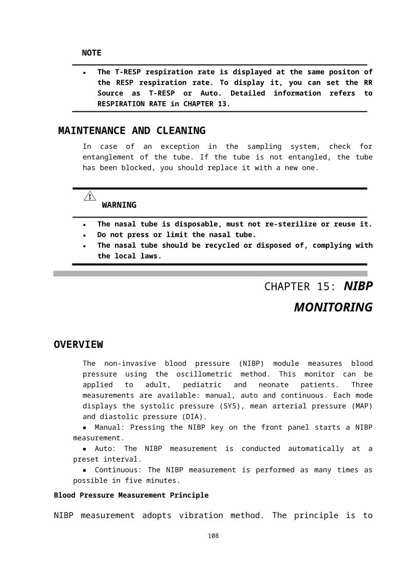
■ Alarm Setting: Selecting this button pops up the following Set Alarm Limits dialog box.
The upper alarm limit, lower alarm limit, alarm switch and alarm printing switch of SpO2 can be set in this dialog box. See ALARM SETTINGS in CHAPTER 5 for detailed information.
■ AVRG.: Select this button, the following menu pops up:
The average period for SpO2 calculation can be set in this menu.5. 4 Beats: The average period is 4 SpO2 periods.6. 8 Beats: The average period is 8 SpO2 periods.7. 16 Beats: The average period is 16 SpO2 periods.
WARNING● Setting the SpO2 upper alarm limit to 100% will disable the upper alarm limit. High
oxygen levels may predispose a premature infant to retrolental fibroplasia. Therefore, the upper alarm limit for oxygen saturation must be carefully selected in accordance with the commonly accepted clinical practices.
PLETH MENUSelecting the PLETH channel label pops up the following menu:
■ Fill Waveform: Fills or unfills the PLETH waveform. It has the same function as the Pleth Fill button in the Display menu.
MAINTENANCE AND CLEANING
NOTE● Clean the sensor and the surface of the probe before and after each use. You can wipe
surfaces with 70% Isopropylic Alcohol or soak the clip for five minutes in Isopropylic alcohol. After soaking the clip, it must be rinsed with water and air-dried prior its use.
● SpO2 sensor must be recycled or disposed of properly, complying with the local laws.
109

Spo2 compensate
During the monitoring the patient Temperature parameter,you will compensate the temperature if you find that the temperature departure some range of the real result as follows:
The spo2 compensate range is from –30% to +30%,the detailed windows as follows:
1.Press the menu key and enter the system setup item
2.Press the system setup menu key and enter the maintenance
setup item
3.Press the function maintenance menu key and enter the
Reserved 1
4.Input the password 1231 and enter the function compensate menu item ,you will do it
for Temperature 、NIBP and SPO2
110
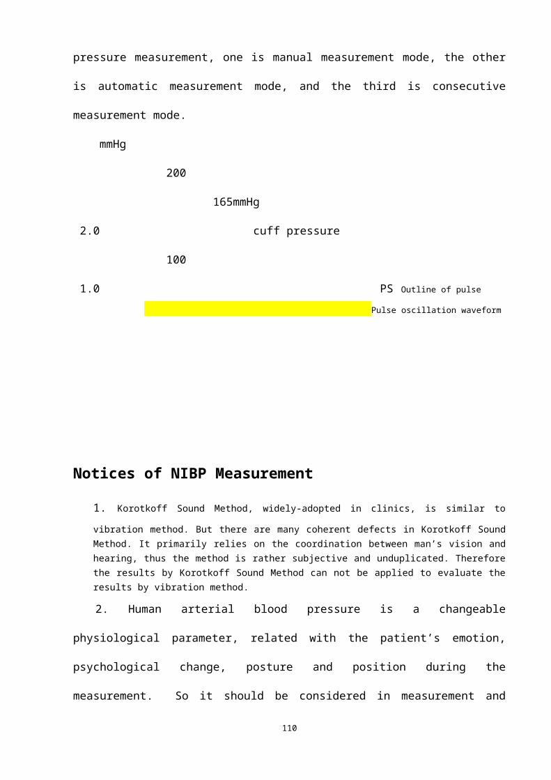
CHAPTER 18: IBP MONITORING
IBP CHANNELSThe monitor provides two channels to measure the invasive blood pressure (IBP, including systolic, diastolic and mean pressures), and displays two channels of waveforms and two parameters. The two channels of waveforms are displayed in a same or different waveform area, differentiated by color. When the two curves overlapped, the curve color will be the color of channel 2. The figure below is the channels displayed in different waveform area:
① Label of channel 1: Selecting this label pops up the menu of channel 1.② Label of channel 2: Selecting this label pops up the menu of channel 2.③ Pressure axis: It is the pressure axis of the waveform displayed on its right side, shown as below:
The bottom horizontal line indicates the location of zero pressure. If a curve dot is displayed higher than this line, it means the pressure of this dot is positive; accordingly, the pressure of the dot, which is lower than this line, is negative.The top horizontal line indicates the maximum pressure of current display gain. The curve line where its pressure is higher than the maximum pressure will be clipped and becomes a section of horizontal line.The height of the waveforms relates to the pressure. And the ratio between height and pressure is specified. Maximum value and Minimum value are listed in the following table:
111
①
②
④
⑤
⑥③
Maximum
0 mmHg
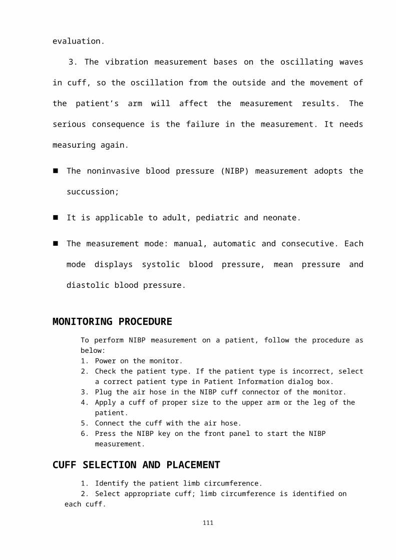
Maximum value on screen Minimum value on screen6 mmHg -1 mmHg10 mmHg -1 mmHg18 mmHg -2 mmHg30 mmHg -3 mmHg60mmHg -6mmHg80mmHg -8mmHg100mmHg -11mmHg120mmHg -13mmHg180mmHg -20mmHg240mmHg -26mmHg300mmHg -33mmHg
The monitor can automatically select a proper ratio according to the phase of the waveform. It also provides a function to adjust the ratio manually. Here we call it two gain modes: Auto mode and Manual mode.④ Status message: Displayed above the waveform. All the possible status messages are listed in the
following table:
Message string Meaning Possible causation
No ResponseThe monitor can not get data from this channel
When the monitor is restarting, this message indicates that the channel has not been started yet, but this message will disappear in 5 seconds.Or the hardware of IBP module does not work properly and needs to be fixed.
Sensor OffThe pressure sensor isn’t connectted to the monitor.
The pressure sensor cable has fallen off from the monitor or from the pressure sensor.
NOT Zero The channel wasn’t zeroed Operator has to zero the monitor after it is started. If not, the measured pressure is unusable.
Auto/ManualThis is a normal working message. It tells the current gain mode and gain ratio.
The channel works properly.
⑤ Waveform of channel 1.⑥ Waveform of channel 2.
IBP PARAMETERThe measured IBP values of two channels are displayed in the parameters area, the right side of the IBP channels, shown as below:
112
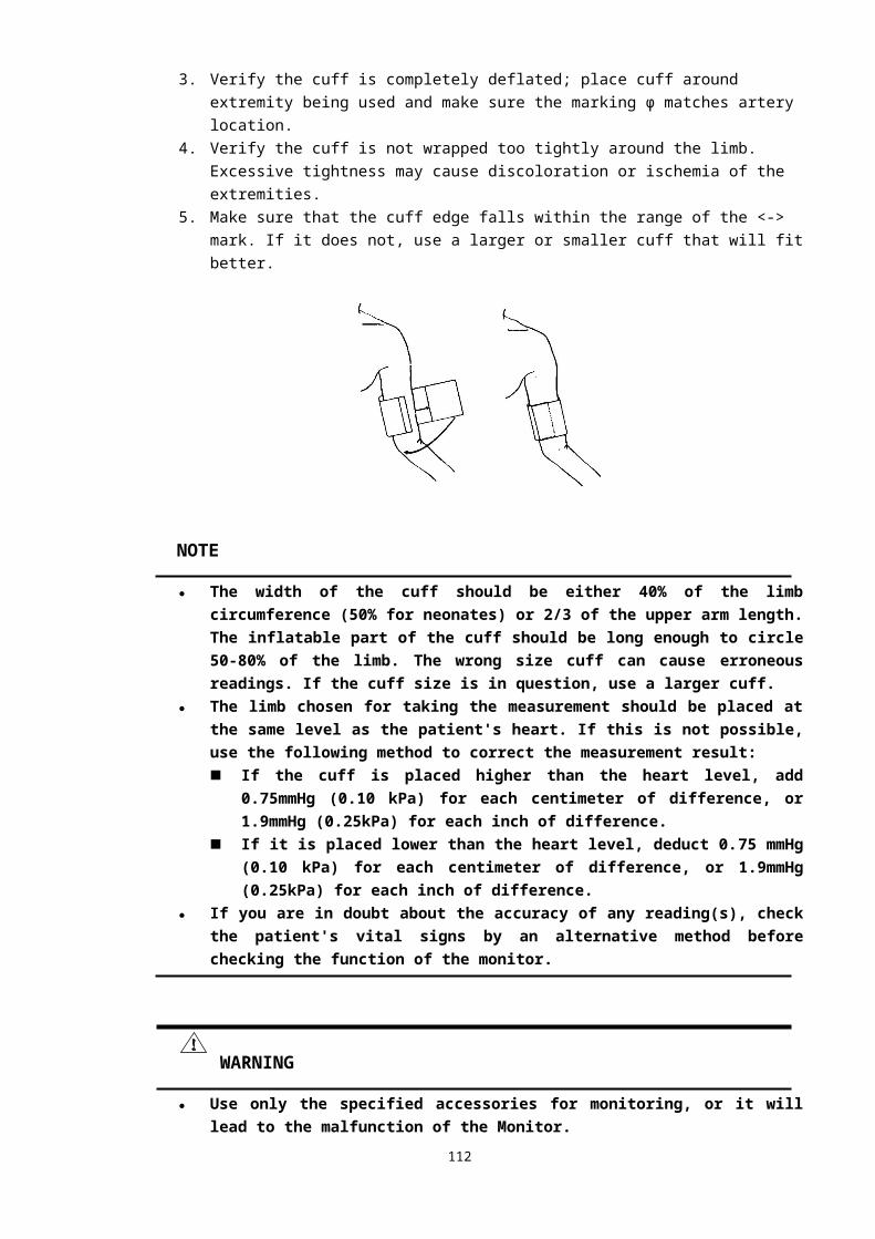
① IBP label of channel 1② Systolic blood pressure (SYS)③ Mean pressure (MEAN)④ Indicates that this area displays the measured IBP values of channel 1.⑤ Diastolic blood pressure (DIA)IBP values can vary in the range from –60mmHg to 300mmHg. Values not in this range will be displayed as invalid pressure, in the form of “---” or “--.-”.But there are more reasons if these pressure values are displayed as invalid values, they are:1. The actual pressure is not in the range from -60 mmHg to 300 mmHg.2. The channel wasn’t zeroed.3. The cable is disconnected or not connected firmly.4. The channel is not calibrated properly.5. In zero processing.6. Monitor is starting.The IBP unit is the same as the NIBP unit. See REGION SETTINGS in CHAPTER 4 for detailed information.
PRECAUTIONS
WARNING● Use only the IBP transducer specified in this manual. Disposable IBP transducers should
not be reused.● Parts and accessories used must meet the safety requirements of the medical electrical
equipment standards.● Avoid conductive connection to the applied part likely to degrade safety.● When the monitor is used with high frequency surgical equipment, do not allow the
transducer and the cable contact the high frequency surgical equipment to prevent the patient from burning caused by leakage current.
MONITORING PROCEDURE1. Plug the pressure cable into the IBP connector on the monitor and power on
the monitor.2. Prepare the pressure line and transducer by flushing the system with
normal saline solution. Make sure the tubing and transducer system is free of air bubbles.
NOTE● In case of any entrapped air in the pressure system, re-fill the system with normal saline.
113
①②③
④⑤
3. Connect the catheter to the pressure line, making sure there is no air present in the catheter or pressure line.
4. Position the transducer so it is at the same level with the patient’s heart, approximately mid-axillary line.
5. Verify the correct label is selected.6. Zero the transducer.
IBP MENU
IBP PARAMETER MENUSelect the IBP parameter label in the parameters area, the following menu pops up:
■ Alarm On/Off: Enables or disables the IBP alarm (including the systolic, diastolic and mean pressure alarms).Alarm enabled: The IBP alarm is turned on, the monitor alarms when the measured IBP
value exceeds the preset alarm limit.Alarm disabled: Icon is displayed on the left side of the IBP parameter label, the IBP alarm
is turned off, and the monitor does not generate alarms when the measured IBP value exceeds the preset alarm limit.
■ Alarm Setting: Selecting this button pops up the following Set Alarm Limits dialog box.
The upper alarm limits, lower alarm limits, alarm switches and alarm printing switches of SYS, DIA and MEAN can be set in this dialog box. See ALARM SETTINGS in CHAPTER 5 for detailed information.
■ Label: Selecting this botton switches the label of this channel. The label recycles in the order listed below:
Label DefinitionART Arterial Blood PressureCVP Center Venous Pressure
114
Pressure transducer
Pessure transducer cable
Monitor3-way
stopcock
Pressure line
Normal salin with heparin
Drip chamber
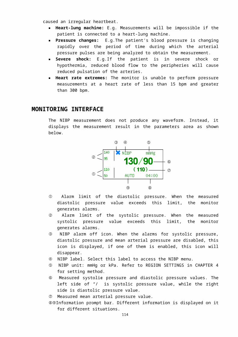
RVP Right Ventricle PressureLAP Left Atria PressureRAP Right Atria PressurePAP Pulmonary Arterial PressureICP Intracranial PressureLVP Left Ventricle Pressure
The selected label will be saved in 5 seconds and displayed in the corresponding channel. It does not take any other effect other than displaying.
IBP CHANNEL MENUSelect the label of a target IBP channel, and the menu of this channel pops up, shown as below. In this menu, we can change the label of the channel, zero the transducer and select the display gain.
LabelIt has the same function as the Label button in the IBP parameter menu. Selecting this button switches the label of this channel.
ZeroIn the first time we select this button, the corresponding channel will perform zero process. And selecting this button again will terminate the zeroing. The system will treat the detected absolute pressure value as the relative zero point. This zero point affects both the pressure values and the waveforms of the channel.Zeroing procedure:1. Disconnect the transducer from the patient.2. Adjust the 3-way stopcock to close the channel leading to the patient. The
transducer is open to the atmosphere through the stopcock.3. Select the Zero button in the IBP channel menu to start zeroing.NOTE● The zeroing funciton is noneffective in sensor off status, it is effective only when the sensor
is connected to the monitor.● Position the transducer at the same level with the patient’s heart, approximately mid-
axillary line.● Perform the pressure zeroing when the monitor is powered on and at measuring intervals
(at least once per day). The zeroing should also be conducted once the transducer cable or catheter is changed.
● Ensure the catheter is static. In the catheter static status, the zeroing will be completed soon.
Gain ModeThis button is to select the display gain mode for the channel. The gain mode switches between Auto and Manual when selecting this button. This function is disabled if the channel wasn’t zeroed.
Adjust GainIf the gain mode of the channel is Manual, we can use this button to increase/decrease display gain. The clockwise for decrease, whereas for increase. This operation zooms in the waveform in vertical direction. This function is also disabled if the channel wasn’t zeroed.
115
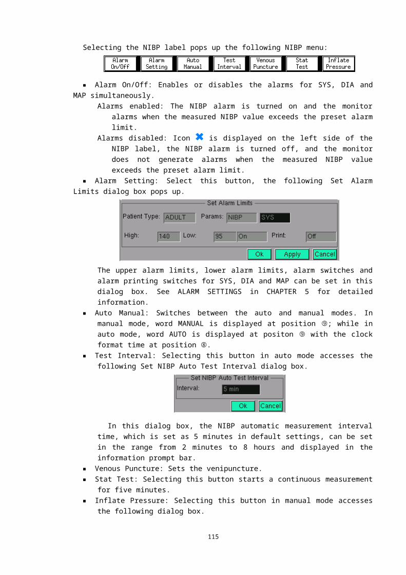
MAINTENANCE AND CLEANING
WARNING● Before cleaning the transducer, make sure the transducer is disconnected from the
monitor, or the monitor is powered off and disconnected from AC power.
CLEANING OF IBP TRANSDUCERAfter the IBP monitoring operation is completed, remove the tubing and the dome from the transducer and wipe the transducer diaphragm with water. To clean the transducer and the cable, wipe them using soap or the detergents listed below:■ Cetylcide■ Wavicide-01■ Wescodyne■ Cidex■ Lysol■ VespheneDo not immerse the connector in any liquid. After cleaning, dry the transducer thoroughly before storing. Slight discoloration or temporary increase of surface stickiness of the cable should not be considered abnormal. If it is necessary to remove the adhesive tape residue from the transducer cable, the double seal tape remover is recommended; use the remover with special caution to minimize the damage to the cable. Acetone, Alcohol, Ammonia and Chloroform, or other strong solvents are not recommended because they are harmful to the vinyl cabling if used for a long time.
NOTE● The disposable transducers or domes must not be reused.● To avoid contamination, the disposable transducers or domes must be reclaimed or
disposed of properly, complying with the local laws.
STERILIZATIONChemical Solution Sterilization
After finishing the cleaning, select an effective sterilant for chemical solution sterilization of the operating room equipment. Buffered glutaraldehyde (e.g. Cidex or Hospisept) is recommended. Do not use quaternary cationic detergents such as zephiran chloride. If the whole unit is to be sterilized, immerse the transducer but not the electrical connector into the sterilant for the recommended sterilizing period. Ensure that the dome has been removed. Then rinse all transducer parts except the electrical connector with sterilized water or saline. The transducer must be thoroughly dried before storing.
Gas SterilizationFor more complete asepsis, use gas sterilization. The transducer should be
116
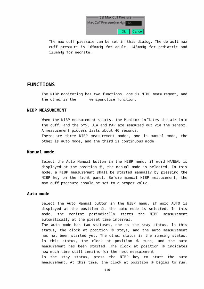
completely dry after cleaning. When ethylene oxide gas is used as the gas disinfectant, follow the operating instructions provided by the manufacturer of the gas disinfectant.
NOTE● The disinfectant temperature must not exceed 70°C (158°F). Plastics in the pressure
transducer may deform or melt above this temperature.
117
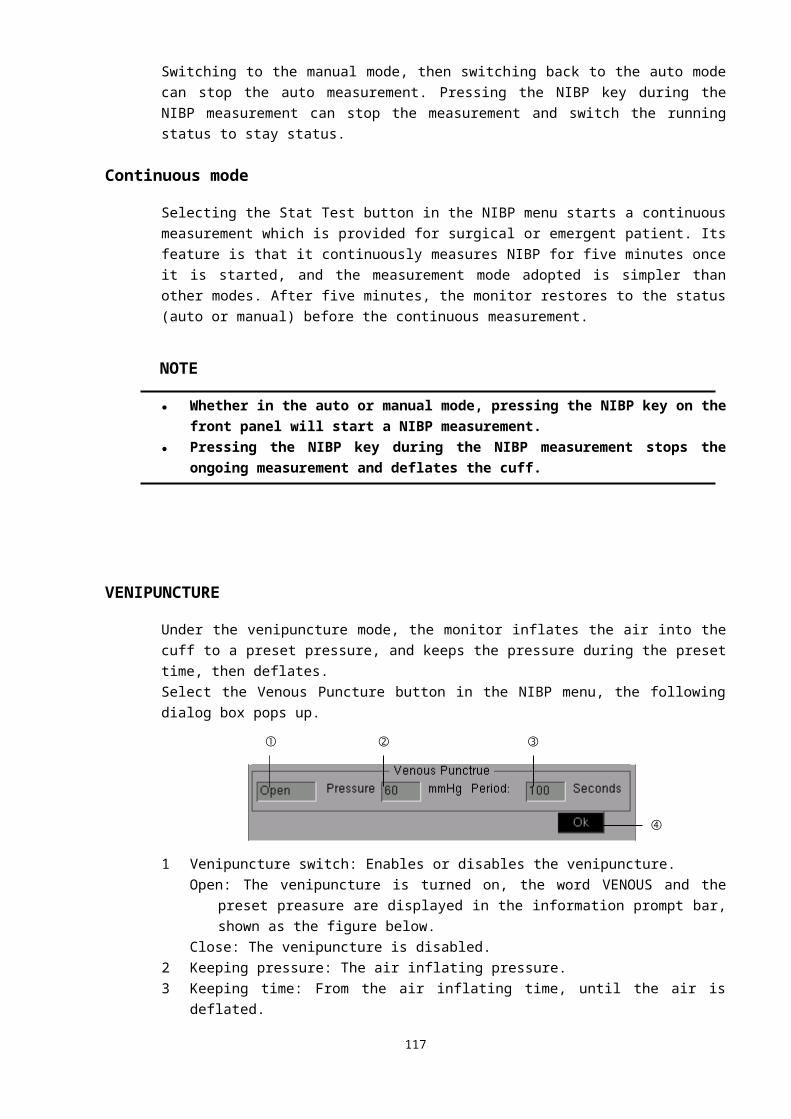
CHAPTER 19: CO2 MONITORING
INTRODUCTIONCO2 monitoring is to monitor the respiration of patient by detecting the concentration of CO2 generated during respiration. The maximum concentration of CO2 at the end of exhalation is called End-Tidal CO2 (EtCO2). The minimum concentration of CO2 at the end of inspiration is called Fractional Inspiratory CO2 (FiCO2). CO2 is generated by cells in the body during metabolizing, and is breathed out via breath system. The concentration of CO2 breathed out from lung reflects directly the situation of metabolizing and breathe system. If the concentration of CO2 is high, it means that metabolizing is excited, such as blood poisoning or acute fever. If the concentration of CO2 is low, it is commonly because the output ability of heart is weak, or the heart stop beating, or the lung soak for the flux of blood is low or oxygen it carried is not enough. Monitoring CO2 is used to warn the doctor of the abnormal of breathe and metabolizing for hocused patient. The concentration of CO2 is represented as a pressure level, with mmHg, kPa or % as its unit. Generally, the acceptable value is 38mmHg (5.1kPa or 5%) when air pressure is 760mmHg. The concentration of CO2 varies very fast from 0% to 5% normally. To detect the concentration of CO2 accurately, the monitor has to be very sensitive.
MONITORING PROCEDUREFollow the procedure specified below to monitor the CO2.1. Plug the dehydration vase into its receptacle, then push its bottom carefully to its position,
shown as the figure below:
2. Connect one end of the sampling line to the dehydration vase.3. Connect the other end of the sampling line to the patient.4. Power on the monitor.5. Enables the displaying of CO2 channel via the Format Setup button in the Display menu.6. Select the Start Pump button in the CO2 channel menu to start air pump.7. The CO2 monitoring starts.
118
Water trap
Water trap receptacle
Sampling line
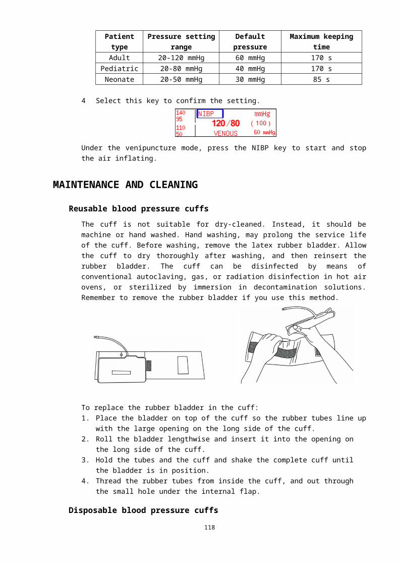
NOTE● To monitor the CO2, the CO2 channel and the air pump must be enabled. If the monitor is
in default settings, these two items must be reset.● When there is no CO2 monitoring, disables the CO2 channel or air pump to prolong its
service life.
MONITORING INTERFACEThe CO2 monitoring displays a CO2 waveform in the channels area and the measured EtCO2 and FiCO2 values in the parameters area.
CO2 CHANNELThe CO2 channel is displayed as below:
①CO2 channel label ②concentration unit ③gain mode ④gain ⑤Prompt information ⑥flow rate ⑦scale ⑧CO2 waveform
Selecting the CO2 channel label pops up the following menu:
■ Gain Mode: Select this button, the gain mode of the CO2 waveform switches between AUTO and MANUAL modes.
■ Adjust Gain: This button is only available in MANUAL mode. Select this button then turn the rotating mouse to adjust the gain. Five grades are available: ×1/2, ×1, ×2, ×4 and ×8. Press the mouse to exit the gain adjustment status when the gain has been chosen, and the CO2
waveform will be displayed in chosen gain.■ Flow Rate: Select this button to adjust the flow rate of the CO2. Three grades are available:
65cc/min, 100cc/min and 150cc/min.■ Waveform Speed: Select this button, the waveform speed switches among 6.25mm/s, 12.5mm/s,
25mm/s and 50mm/s. It is the same as the RESP waveform speed, and switches it will swithes the other one simultaneously. The current CO2 waveform speed can be viewed in the prompt information bar of the RESP channel.
■ Concent. Unit: Select this button, and the concentration unit switches among mmHg, kPa and %.■ Start Pump: Starts or stops the air pump. If the air pump is disabled, this button is displayed as
Start Pump, select it to start the air pump; if the air pump is enabled, this button is displayed as Stop Pump, select it to stop the air pump.
119
① ② ③ ④ ⑤ ⑥
⑦ ⑧
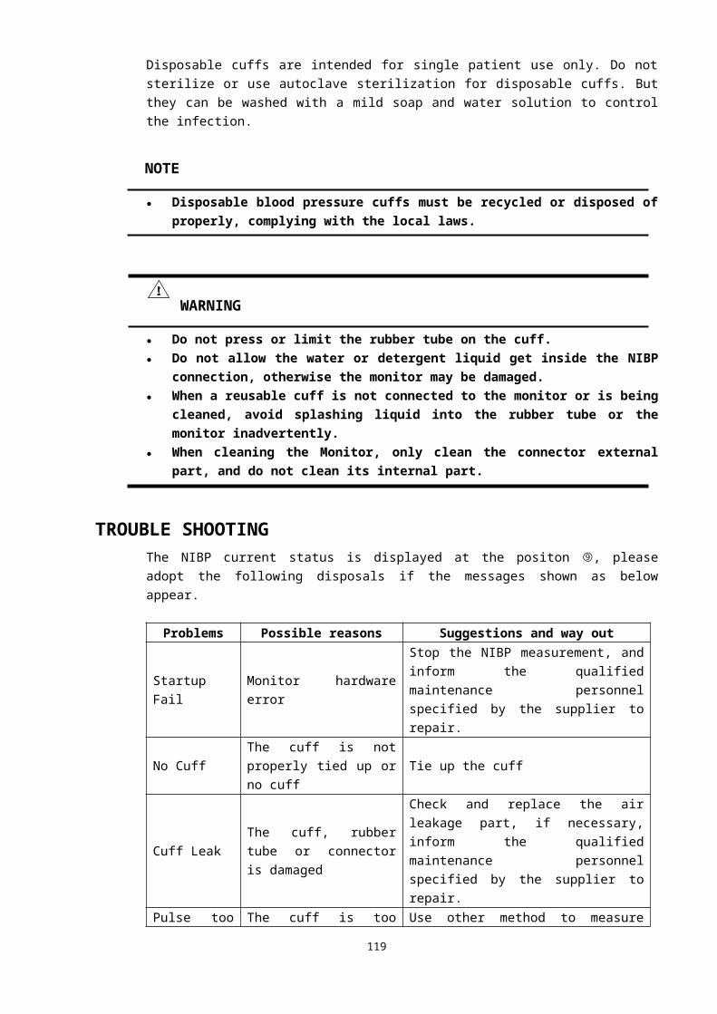
CO2 PARAMETERThe measured CO2 values are displayed as below:
① Upper alarm limit of EtCO2.② Lower alarm limit of EtCO2.③ Measured EtCO2 value.④ Measured FiCO2 value.⑤ Label of EtCO2.
Selecting the EtCO2 label pops up the following menu:
■ Alarm On/Off: Enables or disables the CO2 (EtCO2 and FiCO2) alarm.Alarm enabled: The CO2 alarm is turned on, the monitor alarms when the measured
EtCO2 or FiCO2 value exceeds the preset alarm limit.Alarm disabled: Icon is displayed on the left side of the EtCO2 label, the CO2 alarm is turned
off, and the monitor does not generate alarms when the measured EtCO2 or FiCO2 value exceeds the preset alarm limit.
■ Alarm Setting: Selecting this button pops up the following Set Alarm Limits dialog box.
The upper alarm limits, lower alarm limits, alarm switches and alarm printing switches of EtCO2 and FiCO2 can be set in this dialog box. See ALARM SETTINGS in CHAPTER 5 for detailed information.
■ Concent. Unit: Select this button, the concentration unit switches among mmHg, kPa and %.
120
①
②
③ ④
⑤
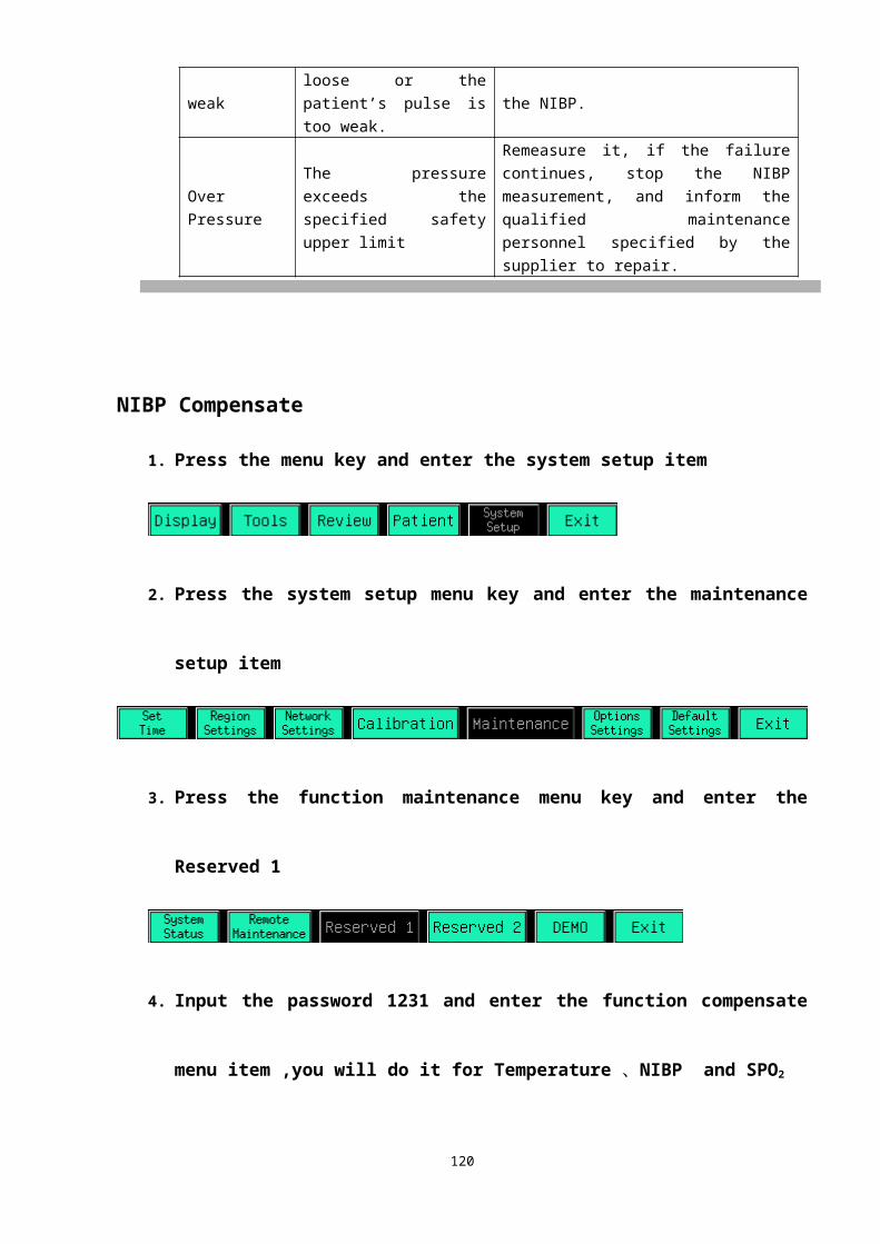
MAINTENANCE AND CLEANING In case of an exception in the sampling system of the CO2 module, check for entanglement of the sampling line. If the sampling line is not entangled, remove the dehydration vase. In this situation, if the dehydration vase is not blocked, the sampling line must have been blocked, and you must replace it with a new one. If the dehydration vase has been blocked, you should replace it with a new dehydration vase.
WARNING● The sampling line is disposable, must not re-sterilize or reuse it.● Do not press or limit the sampling line.● The dehydration vase is used to collect water drops condensed in the sampling airway and
prevent water drops from entering the module. When the collected water reaches to a certain amount, remove the water to avoid blocking the airway.
● In the long-term use, dust or other substances may lower the air permeability of the filter material in the dehydration vase and may block the airway. In this situation, the dehydration vase must be replaced.
NOTE● The sampling line must be recycled or disposed of properly, complying with the local
laws.
121

CHAPTER 20: MAINTENANCE
WARNING● The safety inspection or maintenance, which requires opening the monitor housing, must
be performed by trained and authorized personnel only. Otherwise, equipment failure and possible health hazard may be caused.
INSPECTIONMake sure the qualified service personnel have implemented a complete inspection before putting the monitor into operation, after monitor servicing or system upgrading, or after the monitor has been used for 6-12 consecutive months. This is to ensure the normal operation of the system.Follow these guidelines when inspecting the equipment:■ The environment and the power supply meet the specified requirements.■ Inspect the keys, control knob, connectors and accessories for damage.■ Inspect the power cords for fraying or other damage and check the insulation.■ The grounding cables are correctly connected.■ Only specified accessories like electrodes, sensors and probes are applied.■ The monitor clock is correct.■ The audible and visual alarms functions normally.■ The printer functions normally and the printer paper meets the requirement.In case of any damage or exception, do not use the monitor. Contact the technician in your hospital or our Customer Service immediately.
CLEANING
WARNING● Be sure to shut down the system and disconnect all power cords from the outlet before
cleaning the equipment.
Your equipment should be cleaned on a regular basis. If there is heavy pollution or lots of dust and sand in your place, the equipment should be cleaned more frequently. Before cleaning the equipment, consult your hospital’s regulations for cleaning, disinfecting and sterilizing equipment.The exterior surfaces of the equipment may be cleaned with a clean and soft cloth, sponge or cotton ball, dampened with a non-erosive cleaning solution.
122
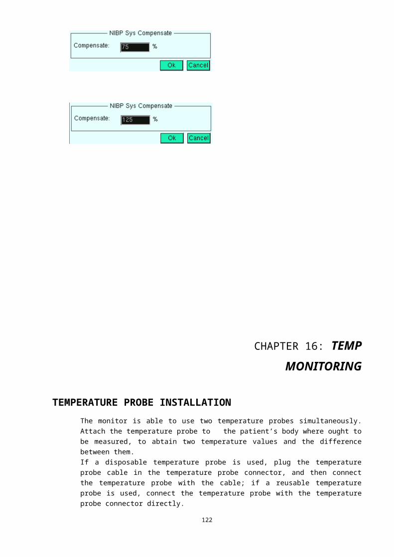
Drying off excess cleaning solution before cleaning the equipment is recommended. Following are examples of cleaning solutions:■ Diluted soap water■ Diluted ammonia water■ Diluted sodium hyoichlo (bleaching agent)■ Diluted formaldehyde (35 to 37%)■ Hydrogen peroxide (3%)■ Ethanol (70%), or Isopropanol (70%)
To avoid damage to the equipment, follow these rules:■ ALWAYS dilute the solutions according to the manufacturer’s suggestions.■ ALWAYS wipe off all the cleaning solution with a dry cloth after cleaning.■ NEVER submerge the equipment into water or any cleaning solution, or pour
or spray water or any cleaning solution on the equipment.■ NEVER permit fluids run into the casing, switches, connectors, or any
ventilation openings in the equipment.■ NEVER use abrasive, erosive cleaners, or cleaners containing acetone.
Failure to follow these rules may erode or fray the casing, or blur lettering on the labels, or cause equipment failures.For cleaning information of accessories, please refer to the chapters for specific patient parameters and the instructions for use of the accessories.
DISINFECTION AND STERILIZATIONSterilization or disinfection may cause damage to the equipment. We recommend the sterilization and disinfection are contained in the hospital’s servicing schedule only when necessary. The equipment should be cleaned prior to sterilization and disinfection.Recommended sterilization material: Alcohol based (Ethanol 70%, Isopropanol 70%), and aldehyde based.
WARNING● Disinfection or sterilization may cause damage to the equipment; therefore, when
preparing to disinfect or sterilize the equipment, consult your hospital’s infection controllers or professionals.
● The cleaning solutions above can only be used for general cleaning. If you use them to control infections, we shall assume no responsible for the effectiveness.
NOTE● ALWAYS dilute the solutions according to the manufacturer’s suggestions and adopt
lower concentration if possible.● NEVER submerge the equipment into water or any solution, or pour water or any
solution on the equipment.● ALWAYS wipe off all the excess liquids on the equipment surface and accessory surface
123

with a dry cloth.● Never use EtO and formaldehyde to disinfect.● Never permit high-pressure and high-temperature disinfection of the equipment and
accessories.
CHAPTER 21: LABELS, PACKAGING, TRANSPORT AND STORING
LABELS
PRODUCT LABELS
G3C label
G3D label
G3F label
G3G label
124
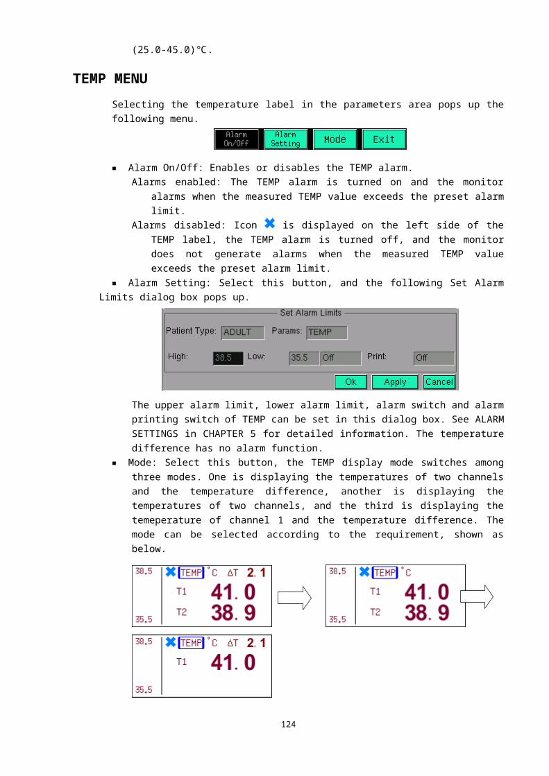
PACKAGING LABELS
There are four symbols on the packing case. Their meanings are shown as below:
Upward
Fragile, handle with care
Keep dry
Stacked not more than four layers
PACKAGINGThe monitor is sealed in a plastic bag and then put in the packing case that is filled with sponge or foam.
TRANSPORT
The monitor can be transported by the aircraft, train or automobile. It has to prevent from strong collision and being placed with corrosive substance.
STORINGThe packed monitor should be stored in the temperature from -20℃ to +50℃, relative humidity not greater than 85%, non-corrosive gas and well-ventilated room.
125
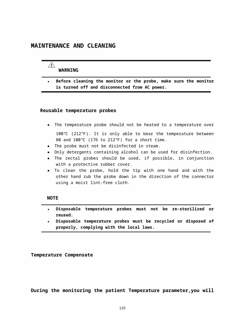
Introduction on the inside module structure and each function module
Basal inside system compositionThe monitor is composed by the multi-function module (ECG, BP SPO2, TEMP, and RESP), operation keyboard, driver Port, network Port ,Intelligent power, AC/DC power, the Central Monitor system, TFT display, and correlative as follows:
Introductions about the main module function.
1 Intelligent power board
The intelligent power board acts as automatic transforming voltage from the 15v to 12v and 5v and so on. on the other hand, it also manages the battery automatic charge-discharge and the overload protection
2 Operation keyboard
Operation keyboard carries out three parts function as follows:
1. Mouse function,similarly to the PC mouse by turning the rotator and let the cursor place some position and then click it to enter the corresponding menu.
2. Execute the measurement of every function parameter by pressing the the corresponding key
3. Provide current pulse to speakerlouder and let it make sound
3 ARM main board
It perform some parts function as follows:1. To communicate and the function board e.g.GAA134,GAA230 etc. and LCD or LED and so on
afer downloaded the Linux program2. To connect the central system by the internet port on it with the net cable3.To connect printer and perform the printing work.
126
ARM main boardPrinting PortNetwork Port Intelligent power
baoardDisplay
AC/DC
GAA230/134/126 multi -function board
Accumulator AC power input
Operating keyboard
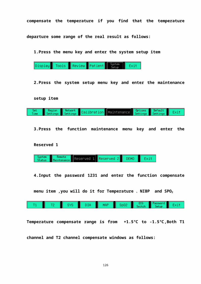
4 GAA230、GAA134 multi-function module
To implement the function of collection, enlarging, controlling, and switching all kinds of function parameters e.g ECG, TEMP, BP, RESP, and SPO2 and so on.
Troubleshooting
G3 monitor trouble, reason and action
Problem Reason Action
No signal on display and no power light when turning on the Monitor
1. The outside receptacle is not connected well
1. Check the connection of power or change
2. The fuse inside the monitor is bad, or the power is bad
2. Change the fuse or power
3. Thhe intelligent power board has some problem
3. Change the intelligent power board or repair it
4. AC/DC power doesn’t work normally
4. Repair it or change it if it won’t be repaired to be good
No signal on the led display but power indication led is light when turning on the Monitor
1. The inverter and 12v power is connected incorrectly
1. Check inverter connection
2.The inverter doesn’t work normally or has some problem
2. Repair the inverter or change it
3. LED doesn’t work normally or has some problem
3. Change LED
No signal on led display
1.There isn’t 5v output in the intelligent power board
1.Change intelligent power board
2.The ARM main board displays unsuccessfully
2.Repair the main board or change it with one OK one
3.The cable of display is not very tight with the display socket
3. Replace the display cable
3. LED doesn’t work normally or has some problem
4. Change LED
ECG signal noise level is bigger than the standard value or appears leading off on the display screen
1.The ECG electrode is used for long time or over the warranty period
1. Change with a new ECG electrode
2.The ECG electrode is not placed correctly
2. Place the ECG electrode according to operation manual
3. ECG cable itself has quality problem
3. Change another ECG cable
4. GAA134 module doesn’t work normally
4. Repair the GAA134 board or change another one that the function is good.
No ECG waveform and
Both GAA230 and GAA134 function board don’t work
Repair them or change another one that the function
127

pump doesn’t work
normally is good.
The blood pressure value is not correct
1.The cuff and tube are barraged or air leaks
1.Check or change the cuff or tube
2.The NIBP cuff is disturbed during the measuring process
2.Keep the patient calm so as to outside interfering
3. The NIBP cuff position isn’t correct
3.Place the NIBP cuff the correct position according to the operation manual
4. The GAA230 board doesn’t work normally
4.Repair the GAA230 board or change it if it can’t be repaired to be good
5.The valve leaks 5. Change the valveThe SPO2 probe led isn’t glow and there is no waveform andvalu or the measuring value isn’t correct
1. The SPO2 probe itself has quality problem
1.Repair the spo2 probe or change it
2. The SPO2 board has some problem
2.Repair the spo2 board or change it
The blood pressure value is
not correct
3. There is strong light around the spo2 probe
2.Cover the probe(for example with towel)
3.The blood circulation by nipped by spo2 probe nail is blocked
3.Help patient recover blood circulation
1.The cuff and tube are barraged or air leaks
1.Check or change the cuff or tube
2.The NIBP cuff is disturbed during the measuring process
2.Keep the patient calm so as to outside interfering
3. The NIBP cuff position isn’t correct
3.Place the NIBP cuff the correct position according to the operation manual
RESP rate is not correct
1.ECG electrode is placed incorrectly
1.Place the ECG electrode correctly
2.GAA134 doesn’t work normally
2. Repair the GAA134 OR change it if it can't be repaired to be good
No sound
1.The loudspeaker is connected incorrectly
1.Reconnect the loudspeaker power cable
2. The keyboard has some mistake
2. Repair the keyboard or change it if it can’t be repaired to be good
128
Electric draw
ECG PART
IRESP PART
129
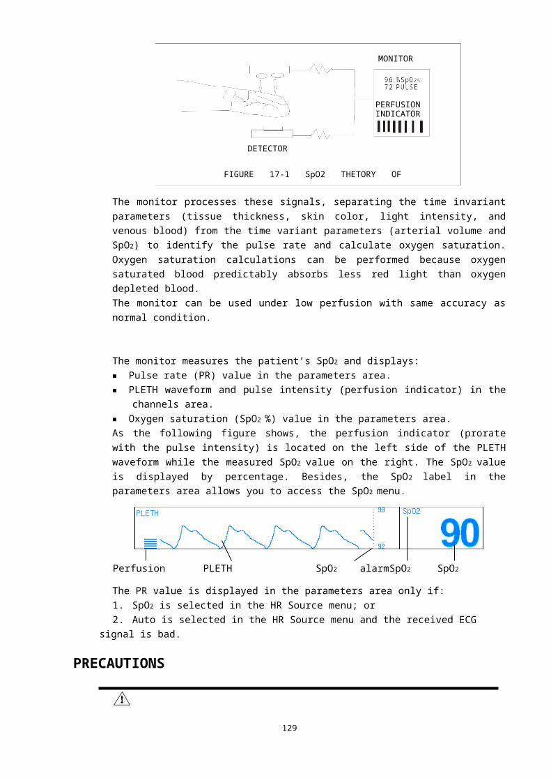
NIBP PART
SPO2 PART
130
TEMP PART
TRESP PART131
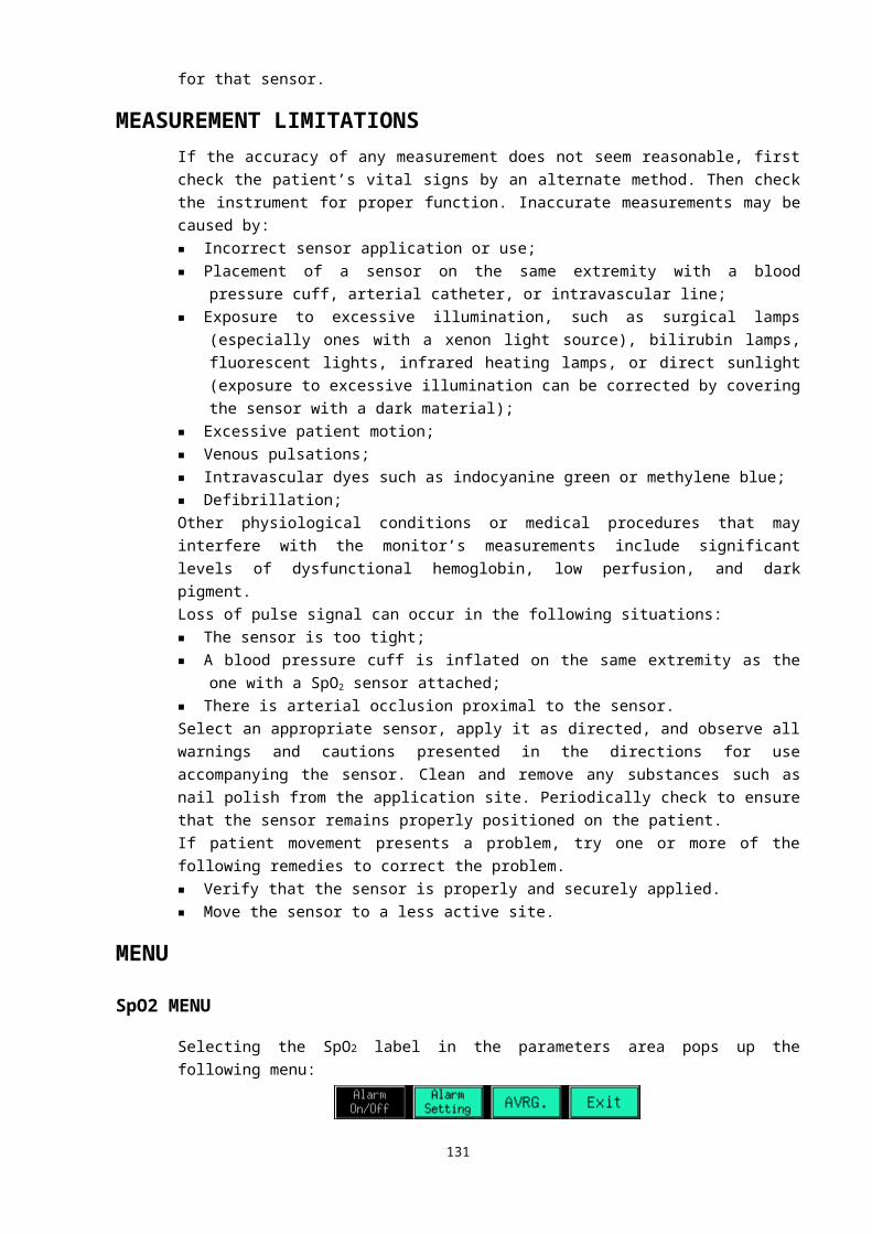
BOM of Function module
S.N.
Mark QTY. Item Main-Sub material
SpecificationPart
number
1 C807,C808,C809 3 SMT Porcelain
capacitor Main material 10pF,50V,±10%,0603,X7R 12110021
2 C7,C8,C805,C806,C811,C812 6 SMT Porcelain
capacitor Main material 15pF,50V,±5%,0603,COG 12115022
3 C128,C129,C130,C131 4 SMT Porcelain
capacitor Main material 100pF,50V,±5%,0603,COG 12110122
132
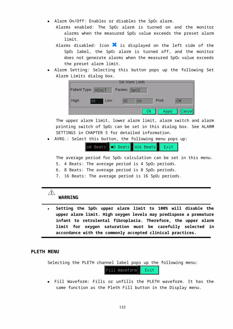
4 C124,C125,C126,C127 4 SMT Porcelain
capacitor Main material 200pF,50V,±5%,0603,COG 12120122
5 C415,C416 2 SMT Porcelain
capacitor Main material 330pF,50V,±5%,0603,COG 12133122
6 C403,C404,C941,C942,C423 5 SMT Porcelain
capacitor Main material 470pF,50V,±5%,0603,COG 12147122
7
C112,C113,C114,C115,C116,C1
17,C132,C133,C136,C208,C209
, 21 SMT Porcelain
capacitor Main material 4700pF,50V,±10%,0603,X7R 12147221
C210,C211,C212,C400,C401,C4
02,C710,C711,C712,C713
8
C121,C122,C123,C219,C220,C
221,C422,C505,C608,C714, 15 SMT Porcelain
capacitor Main material 0.01uF,50V,±10%,0603,X7R 12110321
C715,C914,C915,C916,C1108
9 C134,C135,C137 3 SMT Porcelain
capacitor Main material 0.022uF,50V,±10%,0603,X7R 12122321
10
C1,C2,C3,C4,C5,C100,C101,C1
02,C103,C104,C105,
56 SMT Porcelain
capacitor Main material 0.1uF,50V,±10%,0603,X7R 12110421
C106,C107,C108,C109,C110,C2
00,C201,C202,C203,
C204,C205,C213,C214,C215,C
216,C405,C406,C407,
C408,C409,C410,C411,C412,C5
00,C501,C604,C605,
C700,C701,C702,C703,C800,C
801,C802,
C803,C804,C947,C1100,C110
1,C1102,C1103,C1104,
C1105,C1106,C1107
11 C706,C707,C708,C709 4 SMT Porcelain
capacitor Main material 0.22uF,16V,±10%,0603, X7R 12122421
12 C420,C421,C948,C949 4 SMT Porcelain
capacitor Main material 0.33uF,10V,±10%,0603,X7R 12133421
13
C217,C218,C419,C504,C506,C
507,C600,C601,
18 SMT Porcelain
capacitor Main material
1uF,16V,+80%,-
20%,0603,Y5V12110526C810,C900,C901,C902,C906,C
609
C909,C911,C912,C929
14 C118,C119,C120 3 DIP porcelain
chip capacitor Main material 1uF,63V,±5% 12410501
15 C950 1Al- electrolytic
capacitor Main material
220uF,±20%,25V,-
40 ~105℃ ℃12622712
16 C922,C923 2 SMT Ta
capacitor Main material 2.2uF,10V,A,±16%,-55 ~125℃ ℃ 12222412
17 C944,C945 2 SMT Ta Main material 2.2uF,35V,C,±20%,-55 ~125℃ ℃ 12222435
133

capacitor
18C6,C502,C606,C607,C704,C7
05,C9337
SMT Ta
capacitor Main material 4.7uF,16V,A,±20%,-55 ~125℃ ℃ 12247512
19 C503 1 SMT Ta
capacitor Main material 4.7uF,16V,B,±20%,-55 ~125℃ ℃ 12247527
20 C413,C414,C938,C940 4 SMT Ta
capacitor Main material 4.7uF,25V,C,±20%,-55 ~125℃ ℃ 12247534
21 C206,C207,C937 3 SMT Ta
capacitor Main material
10uF,16V,B,±10%,-
55 ~125℃ ℃12210622
22 C111,C417,C418 3 SMT Ta
capacitor Main material 10UF,25V,D,±20%,-55 ~125℃ ℃ 12210644
23 C602,C603 2 SMT Ta
capacitor Main material
47uF,16V,D,±10%,-
55 ~125℃ ℃12247642
24R814,R815,R816,R817,R818,R
819,R820,R821,R8229 SMT resistor Main material 10Ω,±5%,0603,1/10W 11110021
25 R176 1 SMT resistor Main material 49.9Ω,±1%,0603,1/10W 11150020
26 R800,R801,R802 3 SMT resistor Main material 200Ω,±1%,0603,1/10W 11120120
27 R724,R725 2 SMT resistor Main material 220Ω,±1%,0603,1/10W 11122120
28R716,R717,R824,R825,R826,R
8276 SMT resistor Main material 412Ω,±1%,0603,1/10W 11141120
29 R812,R813 2 SMT resistor Main material 620Ω,±5%,0603,1/10W 11162121
30 R411,R412,R413,R414,R600 5 SMT resistor Main material 680Ω,±1%,0603,1/10W 11168120
31
R180,R224,R225,R226,R506,R
507,R508,R828,R829,R830,
28 SMT resistor Main material 1KΩ,±1%,0603,1/10W 11110220R1100,R1101,R1102,R1103,R11
04,R1105,R1106,R1107,R1108,
R1109,R1110,R1111,R1112,R111
3,R1114,R1115,R1116,R1117
32 R823 1 SMT resistor Main material 1.5KΩ,±1%,0603,1/10W 11115220
33
R410,R505,R603,R803,R804,R
805,13 SMT resistor Main material 2KΩ,±1%,0603,1/10W 11120220
R806,R807,R808,R809,R810,R
811,R428
34 R912,R1127 2 SMT resistor Main material 2.2KΩ,±5%,0603,1/10W 11122221
35 R118,R119,R120,R440 4 SMT resistor Main material 3KΩ,±1%,0603,1/10W 11130220
36 R422 1 SMT resistor Main material 3.57KΩ,±1%,0603,1/10W 11136220
37 R512,R513,R108,R109,R110 5 SMT resistor Main material 3.74KΩ,±1%,0603,1/10W 11137220
38 R606,R607,R1126 3 SMT resistor Main material 4.7KΩ,±1%,0603,1/10W 11147220
39 R415,R416,R417,R418,R504 5 SMT resistor Main material 4.99KΩ,±1%,0603,1/10W 11150220
40 R441 1 SMT resistor Main material 6.8KΩ,±1%,0603,1/10W 11168220
41 R127,R128,R129 3 SMT resistor Main material 8.45KΩ,±1%,0603,1/10W 11185220
42 R419 1 SMT resistor Main material 9.1KΩ,±1%,0603,1/10W 11191220
134
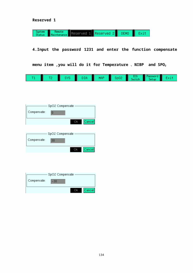
43
R161,R163,R165,R166,R167,R
168,R169,R170,R204,R205,R20
6,
33 SMT resistor Main material 10KΩ,±1%,0603,1/10W 11110320
R207,R208,R209,R210,R211,R2
12,R423,R424,R425,R426,R427
,
R435,R445,R500,R501,R502,R
509,R610,R1122,R1123,R1124,
R1125
44 R1131 1 SMT resistor Main material 11KΩ,±1%,0603,1/10W 11111320
45 R242,R728 2 SMT resistor Main material 15KΩ,±1%,0603,1/10W 11115323
46R177,R178,R200,R201,R202,R
2036 SMT resistor Main material 20KΩ,±1%,0603,1/10W 11120320
47 R514 1 SMT resistor Main material 25.5KΩ,±1%,0603,1/10W 11126320
48
R121,R122,R123,R124,R125,R
126,R227,R228,R229,18 SMT resistor Main material 27KΩ,±1%,0603,1/10W 11127320
R230,R231,R232,R718,R719,R
720,R721,R722,R723
49
R130,R131,R132,R133,R134,R
135,R136,R137,R138,R139,
49 SMT resistor Main material 30KΩ,±1%,0603,1/10W 11130320
R140,R141,R142,R143,R144,R
213,R214,R215,R216,R217,
R218,R219,R220,R221,R222,R
223,R400,R401,R402,R403,
R404,R405,R406,R407,R408,R
409,R511,R704,R705,R706,
R707,R708,R709,R710,R711,R7
12,R713,R714,R715
50 R913 1 SMT resistor Main material 7.5KΩ,±1%,0603,1/10W 11175220
51 R510 1 SMT resistor Main material 40.2KΩ,±1%,0603,1/10W 11140320
52 R503 1 SMT resistor Main material 44.2KΩ,±1%,0603,1/10W 11144320
53R429,R430,R431,R432,R433,R
434,R6017 SMT resistor Main material 47KΩ,±1%,0603,1/10W 11147320
54
R243,R244,R245,R246,R247,R
436,R437,R438, 13 SMT resistor Main material 49.9KΩ,±1%,0603,1/10W 11150320
R439,R900,R901,R902,R903
55
R145,R146,R148,R150,R151,R
153,R160,R162,16 SMT resistor Main material 62KΩ,±1%,0603,1/10W 11162320
R164,R233,R234,R235,R236,R
602,R726,R727
56 R147,R149,R152 3 SMT resistor Main material 95.3KΩ,±1%,0603,1/10W 11195320
57R237,R238,R605,R608,R609,R
831,R1120,R11218 SMT resistor Main material 100KΩ,±1%,0603,1/10W 11110420
135

58 R442,R1118,R1119 3 SMT resistor Main material 130KΩ,±1%,0603,1/10W 11113420
59
R100,R101,R102,R103,R104,R
105,15 SMT resistor Main material 220KΩ,±1%,0603,1/10W 11122320
R106,R107,R111,R179
R112,R113,R114,R116,R117
60 R1134 1 SMT resistor Main material 237KΩ,±1%,0603,1/10W 11124423
61 R171 1 SMT resistor Main material 240KΩ,±1%,0603,1/10W 11124420
62 R909,R910 2 SMT resistor Main material 432KΩ,±1%,0603,1/10W 11143420
63 R906,R908 2 SMT resistor Main material 453KΩ,±1%,0603,1/10W 11145420
64 R1128,R1129,R1130 3 SMT resistor Main material 464KΩ,±1%,0603,1/10W 11146420
65 R239,R443 2 SMT resistor Main material 470KΩ,±1%,0603,1/10W 11147420
66 R420,R421,R604,R1132,R1133 5 SMT resistor Main material 1MΩ,±1%,0603,1/10W 11110520
67R154,R155,R156,R157,R158,R
1596 SMT resistor Main material 3.3MΩ,±5%,0603,1/10W 11133521
68 R700,R701,R702,R703 4 SMT resistor Main material 10MΩ,±5%,0603,1/10W 11110621
69 R172,R173,R174,R175 4 SMT resistor Main material 30MΩ,±5%,0603,1/10W 11130521
70 NTC800 1Thermal-sensitive
resistor Main material 5Ω,4A 11805020
71 VR400,VR600 2 ceramic glaze VR Main material 3266-W-10KΩ,10% 11710303
72VR100,VR101,VR102,VR200
,VR201,VR401,VR700,VR7018
ceramic glaze
VR Main material 3266-W-100KΩ,10% 11710405
73 L907 1 SMT inductance Main material 100uH,CR75-101KC 13210122
74L900,L901,L902,L903,L904,L90
5,L9067
SMT magnetic
bead Main material 100Ω@100MHz,0805,400mA 13010103
75
L1,L2,L3,L4,L100,L101,L102,
L103,L104,L105,L300,
55 SMT magnetic
bead Main material 100Ω@100MHz,0603,200mA 13010112
L301,L302,L303,L304,L305,L30
6,L307,L308,L309,L310,L311,
L500,L501,L502,L503,L504,L60
0,L601,L700,L701,L702,L703,
L704,L705,L706,L707,L708,L70
9,L800,L801,L802,L803,L804,
L805,L806,L807,L808,L809,L81
0,L811,L812,L813,L814,L815
76
D100,D101,D102,D103,D10
4,D105,D106,D107,D200,D400,D
401,
25 SMT diode Main material LL4148,MiniMELF,园柱 15414811D402,D403,D404,D405,D40
6,D407,D408,D409,D800,D801,D
802,
D803,D804,D805
136
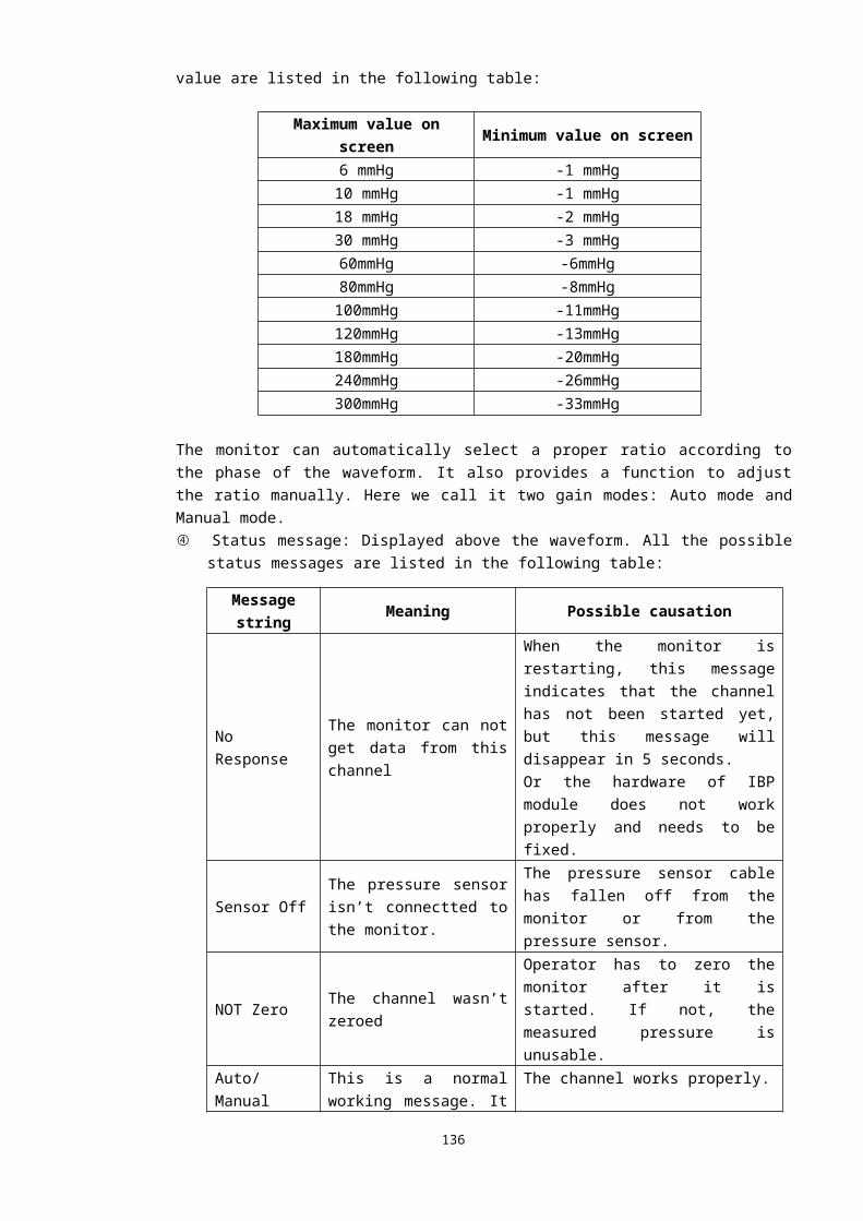
77 D414 1 SMT diode Main material 1N5817 15581711
78 D900 1 SMT diode Main material 1N5822 15582211
79 D412,D413,D600 3 SMT diode Main material ZMM9V1,MiniMELF, Column 15282031
80 D410,D411 2 SMT diode Main material ZMM8V2,MiniMELF, Column 15291031
81 Q200 1 SMT diode Main material TL431,SOT-23-3 15043131
82 D114,D115,D116,D117,D118 5 SMT diode Main materialSMBJ20CA,DO-2144AA,
square15020021
83 Q800,Q801,Q802 3 SMT triode Main material 2SA812,PNP,Mini MOLD 15281211
84 Q806 1 SMT triode Main material BCX5616,NPN,SOT89 15561611
85 Q803,Q804,Q805 3 SMT triode Main material MMBT2222ALT1,NPN,SOT-23 15222221
86 U803,U804,U805 3 SMT OC Main material PS2501L-1,Gull Wing 14250111
87 U800,U801 2 DIP OC Main material HCPL-4504#020,Gull Wing 14450402
88 Y1,Y800 2 DIP X’tal Main material 11.0592MHz,HC-49S,±30PPM 1D110591
89 U100,U101,U102,U103,U200 5 SMT IC Main material DG412DY,SOIC-16 14041202
90 U501 1 SMT IC Main material ADG608BR,SOIC-16 14060801
91 U802 1 SMT IC Main material AT89C2051-12S,SOIC-20 14020513
92
D108,D109,D110,D111,D112,D11
3,D201,13 SMT IC Main material BAT54RSLT1,SOT-23 15054022
D202,D415,D500,D601,D700,D70
1
93 U2 1 SMT IC Main material C8051F020,TQFP-100 14805102
94 U1 1 SMT IC Main materialCY62128DV30LL-55ZI,TSOP1-
3214621281
95 U921 1 SMT IC Main material LM2577S-ADJ,TO-263 14257701
96
U108,U109,U201,U202,U20
3,U400,U401, 13 SMT IC Main material TL074CPW,TSSOP-14 14007404
U500,U600,U700,U701,U702,U11
01
97 U110,U111,U112 3 SMT IC Main material OP4177ARU,TSSOP-14 14417701
98 U104,U105,U106 3 SMT IC Main material OPA237NA,SOT-23-5 14023701
99 U107 1 SMT IC Main material ADG801BRT,SOT-23-6 14080101
100 U900,U901 2 SMT IC Main material MIC5205-3.3BM5,SOT-23-5 14520501
101 U906 1 SMT IC Main material MIC5205-5.0BM5,SOT-23-5 14520502
102 U918,U919 2 SMT IC Main material MIC5205BM5,SOT-23-5 14520503
103 U911 1 SMT IC Main material MIC5270-5.0BM5,SOT-23-5 14527001
104 U915,U916 2 SMT IC Main material MIC5270BM5,SOT-23-5 14527002
105 U205 1 Pressure sensor Main material MPXM2053GS,1320A-02 14205300
106 U904 1 DC/DC module Main material DCM5D6HV-100,DIP16-8 52061001
107 U905 1 DC/DC module Main material DCM5D15HV-100,DIP16-8 52151001
137
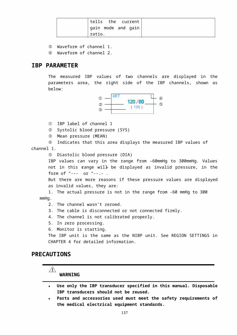
108 U903 1 DC/DC module Main material DCM5S6HV-1W,DIP16-8 52561001
109 J600,J802 2 Electric outlet Main material PH-2A(2.00 Interval ) 19202011
110 J800 1 Electric outlet Main material PH-3A(2.00 Interval ) 19203011
111 J900 1 Electric outlet Main material PH-4A(2.00 Interval ) 19204011
112 J700,J701 2 Electric outlet Main material PH-5A(2.00 Interval ) 19205011
113 J1,J100,J801 3 Electric outlet Main material PH-6A(2.00 Interval ) 19206011
114 J302 1 Electric outlet Main material PH-2*5P(2.0mm Interval ) 19225010
115 J301A 1 Electric outlet Main material 1*5PIN,1.27mm Interval 19205001
116 J301B 1 Electric outlet Main material 1*8PIN,1.27mm Interval 19208001
117 J300 1 Electric outlet Main material 2*7PIN,2.54mm Interval 19214022
118 PCB 1 PCB Main materialGeneral Meditech,Inc. GAA718
V1.051718001
119
R904,R905,R907,R911,R915,R9
16,R917,R918,R919,R920,R181
,R182
12 SMT resistor Main material 0Ω,±5%,0603,1/10W 11100021
120 R914 1 SMT resistor Main material 1.8KΩ,±1%,0603,1/10W 11118220
121 J500 1 Electric outlet Main material 2*4PIN,2.00mm Interval 1922401P
122 R444 1 SMT resistor Main material 30KΩ,±5%,0603,1/10W 11130321
TOTAL: 686
Layout of Circuit Board of Function Board
ECG BOARD PARTBOTTOM PART
138
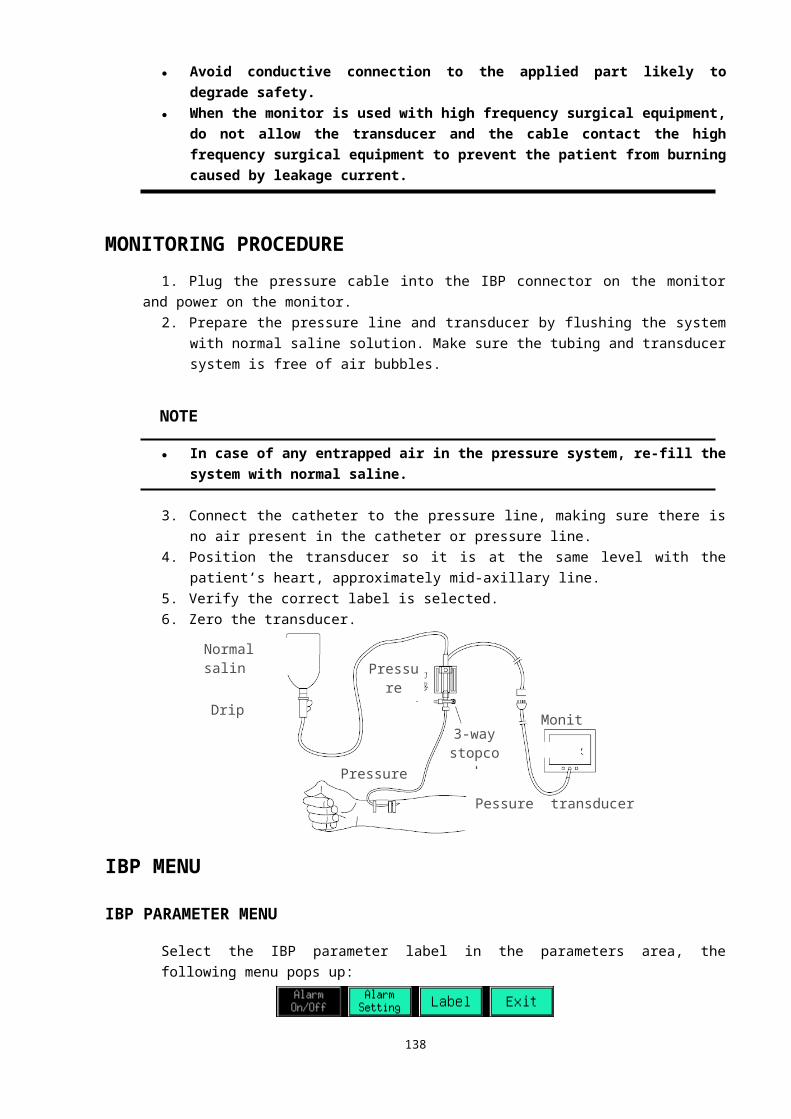
Middle1etch
Middle3etch
1
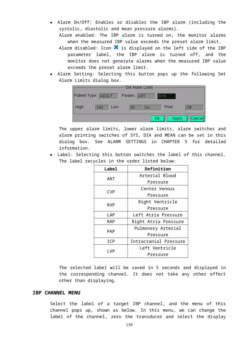
Power part
Topetch
2
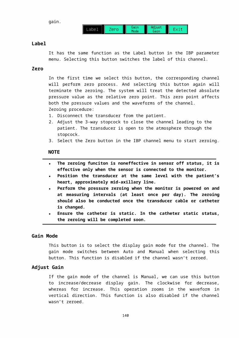
NIBP+RESP PART Bottom PART
GNDETCH PART
3

Poweretch Part
Topetch part
4

Internal pictures
NIBP+RESP FUNTION BOARD
5
ECG FUNTION BOARD
6
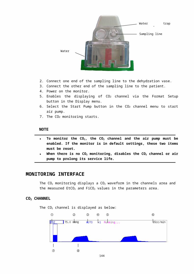
MAIN(ARM) BOARD
7
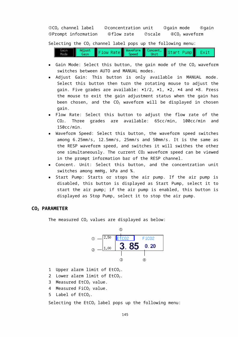
APPENDIX A: PPRODUCT SPECIFICATIONS
ENVIRONMENTAL SPECIFICATIONSOperatingTemperature (5 to 40) °CRelative humidity ≤ 80 %Air pressure (70 to 106) kPaTransport and storageTemperature (-20 to 55) °CRelative humidity ≤ 93 %Air pressure (50 to 106) kPa
8
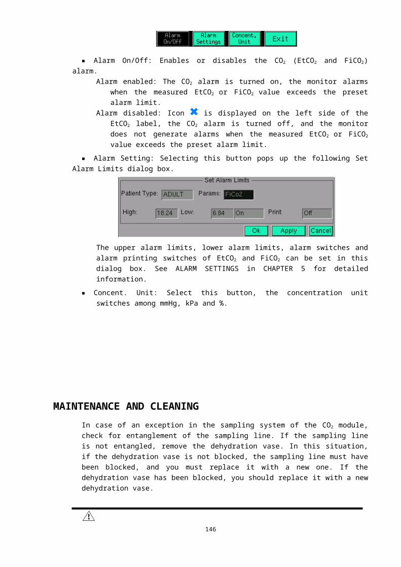
POWER SOURCE SPECIFICATIONSAC mainsInput voltage (100 to 240) VFrequency 50/60 HzPower 80 VAFuse T1.6AL, 250V, 20×5Operating time ≥8 hoursInternal batteryNumber of battery 1Type Lead-acid battery or lithium-ion batterylithium-ion battery (G3C)Nominal voltage 11.1 VCapacity 4000 mAh
Operating time> 1 hour (when the battery is fully charged and the monitor measures the blood pressure every ten minutes)
Charge time 6 hoursLead-acid battery (G3D/G3F)Nominal voltage 12 VCapacity 2400 mAh
Operating time> 1 hour (when the battery is fully charged and the monitor measures the blood pressure every ten minutes)
Charge time 6 hoursLead-acid battery (G3G)Nominal voltage 12 VCapacity 2800 mAh
Operating time> 1 hour (when the battery is fully charged and the monitor measures the blood pressure every ten minutes)
Charge time 6 hours
HARDWARE SPECIFICATIONSDisplayType Color TFT LCD
Size10.4 inches (diagonal, G3C/G3F/G3G)12.1 inches (diagonal, G3D)
Resolution640×480 pixels (G3C/G3F/G3G)800×600 pixels (G3D)
LED indicatorAlarm indicator 1 (red, G3D/G3F/G3G)Power indicator 1 (green)Charge indicator 1 (green)Audio indicator
Speaker Giving audio alarms, heart beat tones, pulse tones and prompt tones for wrong operation
9

Controll
knobs3 (rotating mouse, brightness adjusting knob and volume adjusting knob)
keys7 (power switch, silence key, alarm key, freeze key, NIBP key, print key and main menu key)
ConnectorsPower supply 1 AC power connectorParameter measurement
ECG, RESP, NIBP, SpO2, TEMP1, TEMP2, IBP1, IBP2, CO2
1 standard RJ45 network connector 1 standard color VGA monitor connector 1 printer connector
1 equipotential grounding connector
DATA STORAGETrend data ≥24 hours
Waveform freezingAll the waveforms displayed in the channels area can be stored
ECG SPECIFICATIONS
Lead type3-lead: I, II and III5-lead: I, II, III, aVR, aVL, aVF and V
Lead naming style AHANoise level ≤30 μV
Frequency responseFilter mode: (1 to 25) HzNon-filter mode: (0.5 to 75) Hz
Input offset current ≤0.1 μA
Sensitivity selection 2.5mm/mV (×1/4), 5mm/mV (×1/2), 10mm/mV (×1), 20 mm/mV (×2), 40mm/mV (×4) and AUTO
Sweep speed 6.25mm/s, 12.5mm/s, 25mm/s and 50mm/s
Display linearityCorresponding to ±15 mm of the vertical axis center, the error should be less than ±10 %
Input impedance ≥ 5 MΩCommon mode rejection ≥ 60 dB
Time constantmonitoring lead: ≥ 0.3 sstandard ECG lead: ≥ 3.2 s
Accuracy of standard signal 1 mV ± 5 %Display stability
Time excursionThe excursion after electrified for 60min is not greater than 5mm from the initial position which is the baseline position after electrified for 15min.
Temperature excursion The average baseline excursion is not greater than 0.5mm/℃ in
10

the range from 5℃ to 40℃
Voltage excursionThe baseline excursion is not greater than 1mm and the display sensitivity changes not greater than ±10% when the supply voltage fluctuates transiently
Polarized voltageCorresponding to ±300mV polarized DC voltage, the display sensitivity changes not greater than ±5 %
Hart rate (HR)Measurement range (15 to 300) bpmMeasurement precision 1 bpm or ±1 %, whichever is greaterST segment measurementMeasurement range (-0.8 to +0.8) mVMeasurement precision ±0.02 mV or ±5 %, whichever is greater
RESP SPECIFICATIONSMeasurement technique Thoracic impedance
Lead Optional: lead I, lead II and lead III; default lead IIRRMeasurement range (0 to 120) bpmMeasurement precision 1 bpm or ±5 %, whichever is greaterAlarm allowable deviation ±2 bpm or ±10 %, whichever is greater
NIBP SPECIFICATIONSMeasurement technique Oscillation
Displayed parameters Systolic pressure, diastolic pressure, mean arterial pressure
Mode of operation Manual, auto and continuous
Measurement interval in auto mode
2/3/4/5/6/7/8/9/10/15/20/25/30/35/40/45/50/55 minutes and 1/1.5/2/2.5/3/3.5/4/4.5/5/5.5/6/6.5/7/7.5/8 hours
Measurement time in continuous mode 5 minutes
Measurement range
Systolic pressure (SYS): (4.0 to 36.0) kPa, or (30 to 270) mmHgDiastolic pressure (DIA): (1.3 to 26.7) kPa, or (10 to 200) mmHgMean arterial pressure (MAP): (2.7 to 29.3) kPa, or (20 to 220) mmHg
Measurement precision ≤±0.4 kPa (3 mmHg) or ±2 %, whichever is greaterAlarm allowable deviation ±5 %Maximum standard deviation 5 mmHg
11
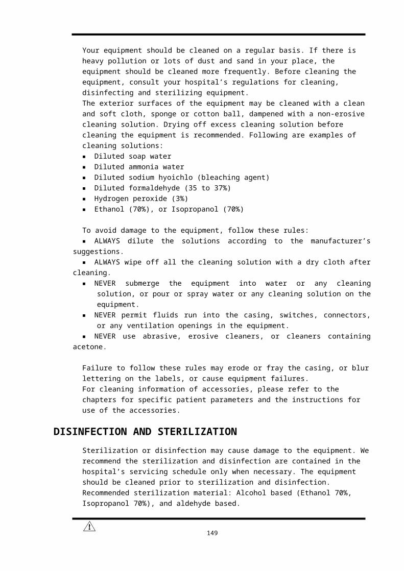
TEMP SPECIFICATIONSNumber of channels 2Displayed parameters T1, T2 and △TMeasurement range (25.0 to 45.0)℃Measurement precision ±0.2 ℃Response time ≤2.5 minAlarm allowable deviation ±0.2 ℃
SpO2 SPECIFICATIONSMeasurement range (0 to 100) %
Measurement precision(70 to 100) %: ±2 %(50 to 69) %: ±3 %(0 to 49) %: Unspecified
Alarm allowable deviation ±2 %
PR SPECIFICATIONSMeasurement range (30 to 250) bpmMeasurement precision 1 bpm or ±2 %, whichever is greaterAlarm allowable deviation ±10 %
IBP SPECIFICATIONSNumber of channels 2
Pressure readings Systolic pressure, diastolic pressure and mean pressure
Pressure labels ART, CVP, RVP, LAP, RAP, PAP, ICP and LVPMeasurement range (-10 to 300) mmHgMeasurement precision ±0.133 kPa (1 mmHg) or ±2 %, whichever is greater
CO2 SPECIFICATIONSMeasurement technique Infrared absorption technique
Displayed parameter EtCO2, FiCO2, RRMeasurement range (0 to 10.0) %
Precision <5.0 %: ±0.28 kPa (2 mmHg)>5.0 %: ±10 % of the read value
APPENDIX B: EMC
The equipment meets the requirements of IEC 60601-1-2:2007.
NOTE
12

● Use of accessories, transducers, and cables other than those specified may result in increased emission and/or decreased immunity of the equipment.
● The equipment should not be used adjacent to or stacked with other equipment, and if adjacent or stacked use is necessary, the equipment should be observed to verify normal operation in the configuration in which it will be used.
● The equipment needs special precautions regarding EMC and needs to be installed and put into service according to the EMC information provided below.
● The equipment may be interfered with by other equipment, even if that other equipment complies with CISPR emission requirements.
● Operation of the device, in the case that the patient physiological signal is lower than the minimum amplitude and/or value specified in the product specifications, may cause inaccurate results.
Table 1
Guidance and declaration — electromagnetic emissions
The equipment is intended for use in the electromagnetic environment specified below.The customer or the user of the equipment should assure that it is used in such an environment.
Emission test Compliance Electromagnetic environment — guidance
RF emissionsCISPR 11
Group 1
The equipment uses RF energy only for its internal function. Therefore, its RF emissions are very low and are not likely to cause any interference in nearby electronic equipment.
RF emissionCISPR 11
Class A
The equipment is suitable for use in all establishments other than domestic and those directly connected to the public low-voltage power supply network that supplies buildings used for domestic purposes.
Harmonic emissionsIEC 61000-3-2
Class A
Voltage Fluctuations/flicker Emissions IEC 61000-3-3
CompliancePst, dt (s)dmax(%)dc (%)
Table 2
Guidance and declaration — electromagnetic immunity
13
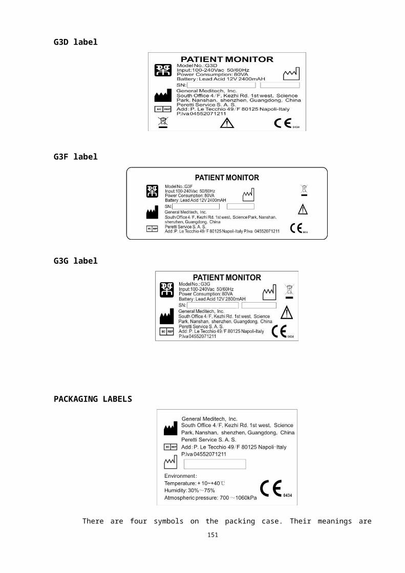
The equipment is intended for use in the electromagnetic environment specified below.The customer or the user of the equipment should assure that it is used in such an environment.
Immunity testIEC 60601 test
levelCompliance level
Electromagnetic environment — guidance
ElectrostaticDischarge (ESD)IEC 61000-4-2
±6 kV contact±8 kV air
±6 kV contact±8 kV air
Floors should be wood, concrete or ceramic tile. If floor are covered with synthetic material, the relative humidity should be at least 30%.
Electrical fastTransient/burstIEC 61000-4-4
±2 kV for power supply lines
±2 kV for power supply lines
Mains power quality should be that of a typical commercial or hospital environment.
SurgeIEC 61000-4-5
±1 kV differential mode
± 2 kV common mode
±1 kV differential mode
±2 kV common mode
Mains power quality should be that of a typical commercial or hospital environment.
Voltage dips, short interruptions and voltage variations on power supply input lines IEC 61000-4-11
<5 % Ut(>95 % dip in Ut)for 0.5 cycle
40 % Ut(60 % dip in Ut)for 5 cycles
70 % Ut(30 % dip in Ut)for 25 cycles
<5 % Ut(>95 % dip in Ut)for 250 S
<5 % Ut(>95 % dip in Ut)for 0.5 cycle
40 % Ut(60 % dip in Ut)for 5 cycles
70 % Ut(30 % dip in Ut)for 25 cycles
<5 % Ut(>95 % dip in Ut)for 250 S
Mains power quality should be that of a typical commercial or hospital environment. If the user of the Model 004 Image Intensifier requires continued operation during power mains interruptions. It is recommended that the Model 004 Image intensifier be powered from an uninterruptible power supply or a battery.
Power frequency (50Hz) magnetic field IEC 61000-4-8
3 A/m 3 A/m
Power frequency magnetic fields should be at levels characteristic of a typical location in a typical commercial or hospital environment.
NOTE: Ut is the A.C. mains voltage prior to application of the test level.
Table 3
14
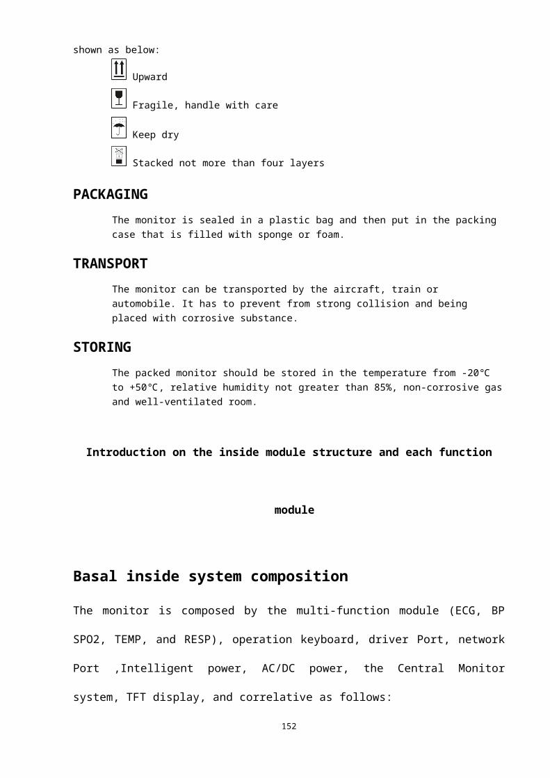
Guidance and declaration — electromagnetic immunity
The equipment is intended for use in the electromagnetic environment specified below.The customer or the user of the equipment should assure that it is used in such an environment.
Immunity testIEC 60601 test level
Compliance level
Electromagnetic environment — guidance
Conducted RFIEC 61000-4-6
Radiated RFIEC 61000-4-3
3 Vrms150 kHz to 80 MHz
3 V/m80 MHz to 2.5 GHz
3 Vrms
3 V/m
Portable and mobile RF communications equipment should be used no closer to any part of the equipment, including cables, than the recommended separation distance calculated from the equation applicable to the frequency of the transmitter. Recommended separation distance
80 MHz to 800 MHz 800 MHz to 2.5 GHz
Where p is the maximum output power rating of the transmitter in watts (W) according to the transmitter manufacturer and d is the recommended separation distance in metres (m).Field strengths from fixed RF transmitter as determined by an electromagnetic site survey a should be less than the compliance level in each frequency range b Interference may occur in the vicinity of equipment marked with the following symbol:
Note — At 80 MHz and 800 MHz, the higher frequency range applies.Note — These guidelines may not apply in all situations. Electromagnetic
propagation is affected by absorption and reflection from structures, objects and people.
15
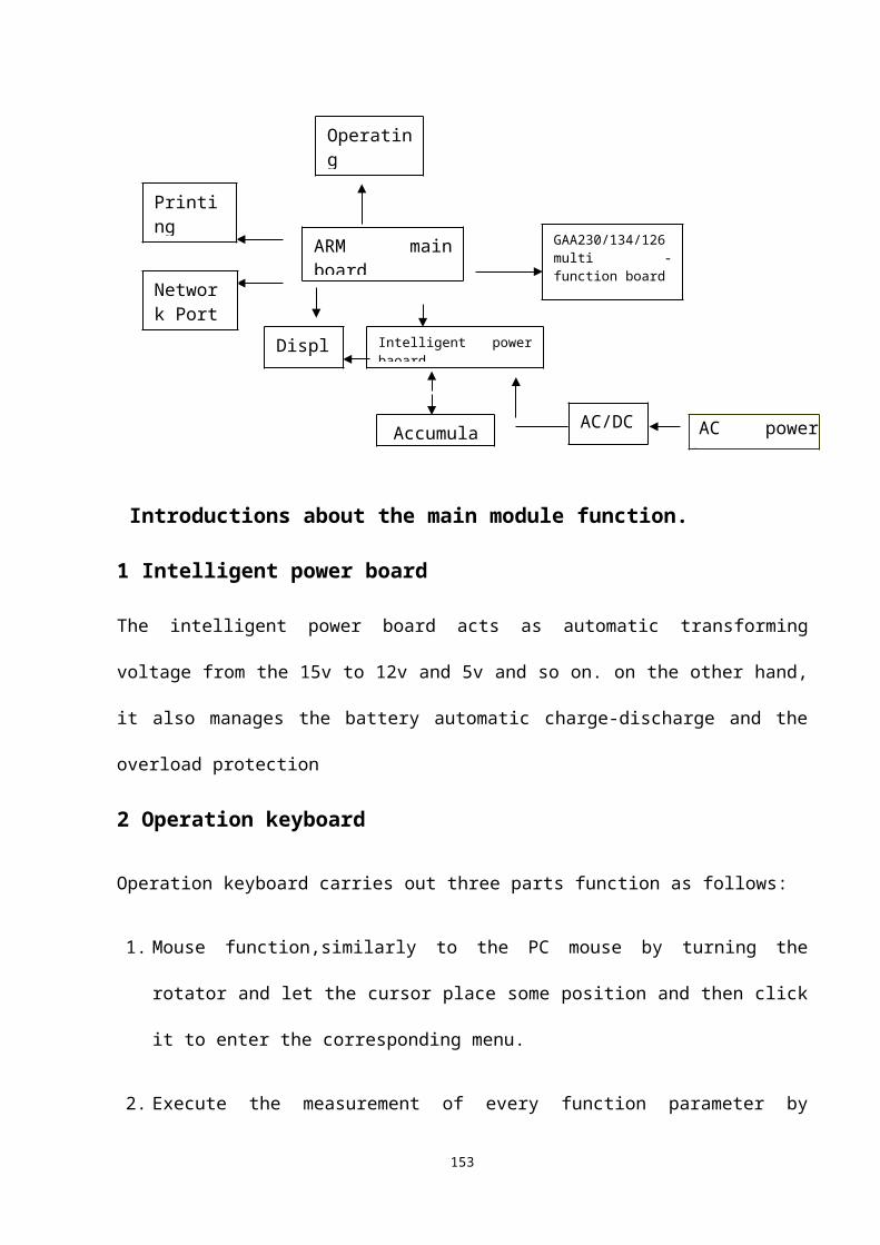
a. Field strengths from fixed transmitters, such as base stations for radio (cellular/cordless) telephones and land mobile radios, amateur radio, AM and FM radio broadcast and TV broadcast cannot be predicted theoretically with accuracy. To assess the electromagnetic environment due to fixed RF transmitters, an electromagnetic site survey should be considered. If the measured field strength in the location in which the equipment is used exceeds the applicable RF compliance level above, the equipment should be observed to verify normal operation. If abnormal performance is observed, additional measures may be necessary, such as reorienting or relocating the equipment.b. Over the frequency ranges 150kHz to 80MHz, field strengths should be less than 3V/m.
16
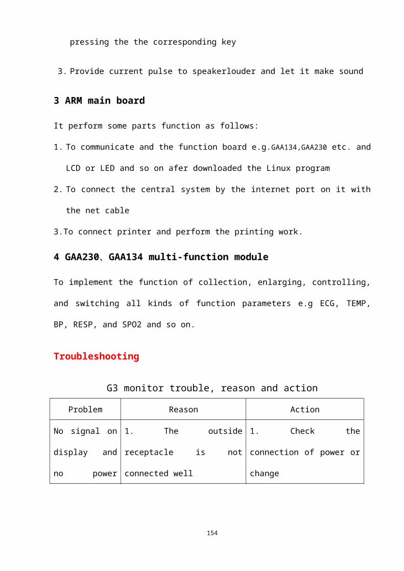
Table 4
Recommended separation distances between portable and mobile RF communication andthe equipmentThe equipment is intended for use in an electromagnetic environment in which radiated RF disturbance are controlled. The customer or the user of the equipment can help prevent electromagnetic interference by maintaining a minimum distance between portable and mobile RF communication equipment (transmitters) and the equipment as recommended below, according to the maximum output power of the communication equipment.Rated Maximum output
power ofTransmitter W
(Watts)
Separation Distance According to Frequency of TransmitterM (Meters)
150 kHz - 80 MHz 80 MHz - 800 MHz 800 MHz - 2.5 GHz
0.01 0.12 0.12 0.230.1 0.37 0.37 0.741 1.17 1.17 2.3410 3.69 3.69 7.38
100 11.67 11.67 23.34For transmitters at a maximum output power not listed above, the recommended separation distanced in meters (m) can be determined using the equation applicable to the frequency of the transmitter, where P is the maximum output power rating of the transmitter in watts (W) according to the transmitter manufacturer.NOTE: At 80 MHz and 800 MHz, the separation distance for the higher
frequency range applies.NOTE: These guidelines may not apply in all situations. Electromagnetic
propagation is affected by absorption and reflection from structures, objects and people.
17


