
DAVmulti
and de
in thSup
It’s the igain the buse of thare also athe con
mo
VINCI is theifunction d
deseveloped oreached be MotoGPpersport cinstrumenbest resulte motorbiavailable tnnection toost commo
e last genedigital dashigned on the expby StarlaneP, Superbikhampionsht any riderts in sport ke, it’s unihe Plug Kito the harneon motorb
Ins
eration hboard
perience e ke, and hips. r needs to and racingiversal andt looms foess of the ikes.
1
stallatiMan
g d r
m
da
E’prd
a
on andnuale d’
DAVINmultifunzi
idall’esperiencampiona
’ lo strumepilota che visultati nedella moto,e sono di
specifal cablaggi
DAV
d opera’install
CI è il crusone di ultideato e svilnza acquisiati MotoGSupersp
ento indispvoglia raggll’uso spor, si installaisponibili afici per la cio originale
diffuse
VINCI‐S
ation mlazione
cotto digitma generaluppato ita da StarP, Superbiport. pensabile pgiungere i mrtivo e agoa universalanche i Pluconnessione delle moe.
S/SX
manual.e e uso.
tale azione
rlane nei ke, e
per ogni migliori onistico lmente ug Kit ne oto più
X

2
DaVinci‐S kit contains ‐ DaVinci‐S dashboard. ‐ Universal bracket with silent blocks. ‐ Universal loom. ‐ USB Data cable for the PC connection. ‐ Installation and operation manual.
DaVinci‐SX extra content ‐ Power Shift connection cables. ‐ Power Shift NRG sensor kit. ‐ Power Shift connection manual. Optionals: ‐ Speed Kit for bikes not fitted with speed sensor. ‐ Cooler temperature sensor. ‐ Plug Kit (Factory loom adaptor for the most common bikes.)
Il kit DaVinci‐S comprende ‐ Cruscotto DaVinci‐S. ‐ Staffa Universale con supporti elastici. ‐ Cablaggio Universale. ‐ Cavo USB per connessione PC. ‐ Manuale di installazione ed uso.
Contenuto extra DaVinci‐SX ‐ Cavi di connessione Power Shift. ‐ Kit sensore Power Shift NRG. ‐ Manuale di connessione Power Shift. Accessori opzionali: ‐ Speed Kit per moto sprovviste di sensore velocità. ‐ Sensore temperatura liquido refrigerante. ‐ Plug Kit di connessione (Adattatore di fabbrica per cablaggio originale delle moto
più comuni).

3
Contents
Introduction………………………………………………………….5
Intruducing the GPS technology………………………………5
Front Panel………………………………………………………………5
Installation of DaVinci……………………………………………6
DaVinci power supply connection....………………………..7
Engine RPM wire connection…………………….……………..7
Connecting warning lights..………………….………………….8
Connection of the speed signal input wire for gear
indication and odometer or mounting the Speed
kit…………………………………………………………………………….9
Connecting the engine cooler temperature wire…...11
Main screen…………………………………………………………13
Setting the engine RPM reading parameters………….15
Setting the distance reading parameters..................15
Setting the warning lights………………………………….….17
Setting the cooler temperature reading ………………..20
Updating the DaVinci firmware………………………………22
Checking the firmware version installed……………..…22
Downloading the update…………………………………….…23
GPS signal acquisition………………………………………..…..23
Configuration…………………………………………………..….24
Setting the Freeze time…………………………….…………...24
Aligning the GPS clock to the local timezone………….25
Setting the LED Bar full scale…………………….……………26
LED Bar type choice……………………………………………….27
Setting the shift light……………………………………………..28
Selection of the units of measurement.…………………28
Gear programming………………….. …………………………..29
Gear learning……………………….. ..…………………………….30
Setting the odometer…………………………………………….31
Quick shifter feature (only on DaVinci‐SX)……………32
Installation……………………………………………………………32
Contenuti
Introduzione……………………………………………………………5
Introduzione alla tecnologia GPS……………………………..5
Pannello Frontale…………………………………………………….5
Installazione di DaVinci…………………………………….…….6
Connessione dell’alimentazione di DaVinci………….…..7
Connessione cavo lettura Regime Motore………………..7
Connessione dei segnali per le spie………………………..…8
Connessione cavo lettura segnale velocità per
indicazione marcia e distanza percorsa o montaggio
dello Speed Kit……..…………………………………………………..9
Connessione cavo temperatura liquido refrigerante.11
Schermata principale……………………………………….……13
Impostazione dei parametri di lettura RPM…………….15
Impostazione dei parametri di lettura dei chilometri
percorsi…………………………………………………………………..15
Impostazione delle spie………………………………………..…17
Impostazione della lettura di temperatura liquido
refrigerante………………………………………………………….…20
Aggiornamento del firmware di DaVinci………………….22
Verifica della versione di firmware installata…………..22
Scarico dell’aggiornamento…………………………………….23
Acquisizione del segnale GPS…………………………………..23
Configurazione…………………………………………….……….24
Impostazione del tempo di visualizzazione a fine
giro…………………………………………………………………………24
Allineamento dell’orologio GPS con il fuso orario……25
Impostazione del fondo scala della Barra LED …….….26
Scelta del tipo di Barra LED……………………………………..27
Impostazione del flash di fuori giri…………………………..28
Selezione delle unità di misura………………………………..28
Programmazione delle marce………………………………….29
Apprendimento dei rapporti……………………………………30
Impostazione del contachilometri………………………..…31

4
Power shift setting………………………………………………...33
Setting the cut off threshold………………………………....34
Direction of operation……………………………………………34
Setting the sensitivity…………………………………………….35
Inverting the electric contact type…………………….…..37
Track management……………………..……………………...38
Learning the finish line and intermediates positions
……………………………………………………………………………..38
Storing the coordinates of the finish line and
intermediates positions…………………………………………39
Loading the track coordinates…………..…………………..40
Analysis of the stored times……..……………………………41
Managing the hour meters…………..…………………….….42
Resetting the hour meters…….……………………………….42
Memory management…………………………………………43
Session recording…………………………………………………..43
Checking the memory in use………………………………….44
Memory clearing……………………………………………………44
Memory formatting……………………………..………………..45
Computer connections………………………………………...47
USB cable connection………..…………………………………..47
Configuring the Bluetooth connection………………..…48
Protecting the Bluetooth connection………………….….51
Cleaning the surfaces………………………………………….….51
Warranty……………………………………………………………….52
Notes…………………………………………………………………….52
Funzione di cambio elettronico (solo su DaVinci‐SX)...
……………………………………………………………………………..32
Installazione……………………………………………………………32
Impostazione di Power Shift……………………………………33
Taratura della soglia di intervento…………………………..34
Verso di funzionamento………………………………………….34
Regolazione della sensibilità……………………………………35
Inversione del contatto di azionamento………………….36
Gestione circuiti…………………………………………………...38
Apprendimento della linea di traguardo e degli
intermedi……………………………………………………………….38
Memorizzazione delle coordinate di traguardo e
intermedi……………………………………………………………….39
Richiamare le coordinate di un circuito…………………..40
Analisi dei tempi memorizzati…………………………………41
Gestione dei contaore…………………………………………….42
Azzeramento dei contaore………………………………………42
Gestione della memoria…………………………………….….43
Registrazione delle sessioni…………………………………….43
Verifica della memoria utilizzata……………………………..44
Cancellazione della memoria…………………………………..44
Formattazione della memoria…………………………………45
Collegamenti con il computer………………………….……47
Connessione con cavo USB……………………………………..47
Impostazione della connessione Bluetooth…….………48
Protezione della connessione Bluetooth…………………51
Pulizia delle superfici……………………………………………….51
Garanzia………………………………………………………………….52
Note………………………………………………………………………..52

5
Introduction Introducing the GPS technology
GPS is the acronym of "Global Positioning System", a satellite positioning system for global and continuous coverage managed by the USA Defence Department. The navigation system is subdivided into the following components: • a group of 24 operating satellites plus
some spare ones • a network of ground stations for
system management • A GPS receiver Satellites elliptically orbit at a distance of about 20200 km so that at least 6 satellites can always be seen from any place on the earth. Every single satellite transmits a radio signal specifying exact time and its position to enable the GPS receiver – knowing the exact position of at least 4 satellites – to calculate the position of the receiver in the space, the current accuracy of which is usually guaranteed even below 1 m. The GPS positioning service is free for end users only requiring the GPS receiver to be able to use it.
IntroduzioneIntroduzione alla tecnologia GPS
GPS è l'acronimo di "Global Positioning System", un sistema di posizionamento satellitare, a copertura globale e continua, gestito dal dipartimento della difesa statunitense. Il sistema di navigazione si articola nelle seguenti componenti: • un complesso di 24 satelliti in funzione
più alcuni di scorta • una rete di stazioni a terra per la
gestione del sistema • un ricevitore GPS I satelliti orbitano a circa 20200 Km su orbite ellittiche in modo che almeno 6 satelliti siano sempre visibili in qualunque luogo sulla terra. Ogni satellite trasmette un segnale radio che indica l'ora precisa e la sua posizione. In tal modo il ricevitore GPS, conoscendo l'esatta posizione di almeno 4 satelliti riesce a calcolare la posizione nello spazio del ricevitore stesso, con una precisione attuale che arriva anche a livelli inferiori a 1 m. Il servizio di posizionamento GPS è gratuito per gli utenti finali, i quali necessitano solo del ricevitore GPS per poterlo utilizzare.
Front panel The Front Panel of the DaVinci contains:
• Engine RPM Bar • SHIFT LIGHT • Settable ALARM LEDS • BEST LAP LED • DATA RECORDING LED • LCD BACKLIT DISPLAY
Pannello frontale Il pannello frontale di DaVinci presenta:
• Barra lettura RPM • FLASH DI FUORIGIRI • LED ALLARMI impostabili • LED BEST LAP • LED DATA RECORDING • DISPLAY LCD RETROILLUMINATO

• LIGba
• KE
InstallDaVinci imotorbikloom andpurchasefollow th
Carry out
1. Rem2. Che
ins3. Rem
releloo
4. Driinsthrthe
GHT SENSOar brightneEYPAD
ation ofs installed ke supportd bracket sed the Plughe instructi
the followmove the meck that therted. move the oease the coom. ll the factotall the 3 Sread supplie holes ava
OR for autoess regulat
f DaVinon the oris through supplied. Ifg Kit for a son supplie
wing installamotorbike he ignition
original daonnector f
ory frame iSilent Blockied using thailable on t
omatic RPMion
ci ginal the univerf you specific biked with the
ation stagefairing. key is not
shboard anfrom the
n order to ks with M4he positionhe univers
6
M
rsal
e e kit.
•
•
Ins DaVdellavetle is
es:
nd
4‐n of sal
Segu1
2
3
4
• SENSORautoregbarra L
• TASTIER
stallazio
Vinci si insta moto conte acquistastruzioni in
uire le segu1. Rimuov
cupolin2. Control
accensi3. Rimuov
sgancia4. Predisp
telaiettoelastici forniti b
RE LUMINOgolazione lED RA
one di D
alla sul telan i supportato il Plug K esso cont
uenti istruzvere la careo. lare che laone non sivere il cruscre il conneorre le foro originaleSilent Blocbasandosi s
OSITA’ esteuminosità
DaVinci
aietto origti elastici foKit specificenute.
zioni: enatura e il
chiave di a inserita. cotto originettore dal catura da 4e per i 3 supck con filettsulla posizi
erna per della
inale orniti. Se co seguite
l
nale e cablaggio.mm. Sul pporti to M4 ione dei
7
bracket provided. 5. Mount the 3 Silent Blocks on the
bracket in position corresponding to the 3 holes made on the frame.
6. Fix DaVinci onto the bracket using the 4 M3‐thread rubber insertions with the specific M3 screws. Attention! Never remove the Silent Block supports between the dashboard and the bike frame.
7. Follow the connection instructions below.
8. Once the connections have been completed insert the ignition key and turn it in the ON position.
DaVinci will be switched on.
ATTENTION! The connectors at the back of DaVinci can be the same as those used on some mass‐produced motorbikes, anyway never connect the motorbike harness directly with the main connector because internal contacts are different and the connection would definitively damage DaVinci and motorbike electronics.
DaVinci power supply connection Connect the Red power supply wire to a key‐switched +12V and the Black GND wire to the chassis or to any ground point, such as the Negative of the battery. Engine RPM wire Connection DaVinci fits to different inputs for the
fori disponibili sulla staffa di supporto fornita nella confezione.
5. Fissare sulla staffa i 3 supporti elastici nella posizione opportunamente definita.
6. Fissare DaVinci alla staffa con i quattro inserti elastici tramite le apposite viti M3. Attenzione! Non rimuovere mai i supporti Silent Block tra il cruscotto e il telaietto.
7. Seguire le istruzioni di connessione del presente manuale.
8. Una volta terminate le connessioni inserire la chiave di accensione e portarla in posizione ON.
DaVinci si accenderà.
ATTENZIONE! I connettori sul retro di DaVinci possono essere dello stesso modello di quelli usati su alcune moto di serie, in ogni caso i cablaggi della moto non vanno mai collegati direttamente al connettore principale in quanto i contatti interni sono diversi e il collegamento danneggerebbe irreparabilmente DaVinci e l’elettronica della moto.
Connessione dell’ alimentazione di DaVinci
Connettere il cavo Rosso di alimentazione ad un +12V sotto chiave e il cavo Nero di massa al telaio o ad un qualsiasi punto di massa, come il Negativo della batteria. Connessione cavo lettura Regime Motore DaVinci è dotato di due ingressi diversi per
8
engine speed reading, respectively connected to the VIOLET wire for low voltage signals (square wave 0‐5V or 0‐12V) or to the ORANGE wire for high voltage inputs (0‐150V) that will never have to be kept connected contemporaneously.
A. Low voltage connection: Connect the VIOLET wire to the RPM (Tacho) signal output wire that goes from the ECU to the connector of the factory instrument panel. If you connect this wire the ORANGE wire will not have to be connected.
B. High voltage connection: Connect the ORANGE wire to the driver wire of one of the ignition coils. If you connect this wire the VIOLET wire will not have to be connected.
ATTENTION! Don’t connect absolutely the VIOLET wire to any of the ignition coils wires or to other wires with voltage higer then the specified in order to void any damage to the engine speed input channel. Connecting warning lights DaVinci is able to control Neutral, Oil Pressure, Fuel Reserve, Beam warning lights. The determination of warning lights switching signals can’t be standardized because of the different ways of activation used by the makers for each model, so warning lights functioning is not guaranteed on DaVinci Universal version even if the powerful software allows a very wide possibility of configuration for most of the bikes in the current productions.
effettuare la lettura del regime motore, rispettivamente collegati al filo VIOLA per segnali in bassa tensione (onda quadra 0‐5V oppure 0‐12V) oppure al filo ARANCIONE per ingressi in alta tensione (0‐150V) che non dovranno mai essere collegati in contemporanea.
A. Connessione in bassa tensione: Connettere il cavo VIOLA al cavo del segnale RPM (Tacho) che dalla centralina va al connettore del pannello strumenti originale. Se viene collegato questo filo, il filo ARANCIONE non dovrà essere collegato.
B. Connessione in alta tensione: Connettere il filo ARANCIONE al filo di pilotaggio di una delle bobine accensione. Se viene collegato questo filo, il filo VIOLA non dovrà essere collegato.
ATTENZIONE! Non collegare assolutamente il filo VIOLA ai fili delle bobine o ad altri fili che possono avere tensioni superiori a quanto specificato per evitare di danneggiare il canale di lettura giri motore. Connessione dei segnali per le spie DaVinci gestisce le spie di Folle, Pressione Olio, Riserva Carburante, Abbaglianti. Non è possibile standardizzare il segnale di accensione delle spie a causa dei differenti modi di attivazione usati dalle case produttrici per ogni modello, quindi il funzionamento delle spie di allarme non è garantito sulla versione Universale di DaVinci anche se l’avanzato software permette larghe possibilità di configurazione per la maggior parte delle moto attualmente in produzione.
9
Neutral = Blue wire Can be connected to the wire of the specific light on the harness going to the factory dashboard or directly to the wire coming out from the neutral switch inside the gearbox. Oil= White wire Can be connected to the wire of the specific light on the harness going to the factory dashboard or directly to the wire coming out from the oil sensor inside the engine. Fuel=Yellow wire Can be connected to the wire of the specific light on the harness going to the factory dashboard or directly to the wire coming out from the fuel sensor on the tank. Beam=Grey wire Can be connected to the wire of the specific light on the harness going to the factory dashboard or directly to the wire supplying the power to the beam light.
Folle= filo Blu:Può essere collegato al filo di accensione della rispettiva spia sul cablaggio che arriva al cruscotto originale oppure direttamente al cavo dell’interruttore del folle in uscita dalla scatola del cambio. Pressione Olio=filo Bianco: Può essere collegato al filo di accensione della rispettiva spia sul cablaggio che arriva al cruscotto originale oppure direttamente al cavo del sensore olio in uscita dalla carter motore. Carburante=filo Giallo: Può essere collegato al filo di accensione della rispettiva spia sul cablaggio che arriva al cruscotto originale oppure direttamente al cavo del sensore di riserva in uscita dal serbatoio carburante. Abbaglianti=filo Grigio: Può essere collegato al filo di accensione della rispettiva spia sul cablaggio che arriva al cruscotto originale oppure direttamente al cavo di alimentazione del faro abbagliante.
Connection of the Speed signal input wire for gear indication and odometer Or mounting the Speed Kit (Optional for bikes with mechanical speed transmission) Connect the GREEN wire to the Speed signal output wire that goes from the speed sensor 8usually positioned on one of the wheels or on the gearbox) to the connector of the factory instrument panel. If on your bike there is no speed sensor and the speed value is sent to the speedometer
Connessione cavo lettura segnale Velocità per indicazione marcia e distanza percorsa O montaggio dello Speed Kit (Opzionale per moto non dotate di segnale velocità elettronico) Connettere il cavo VERDE al cavo di lettura Velocità che va dal sensore velocità (solitamente posizionato su una delle due ruote o in uscita dalla scatola del cambio) al connettore del pannello strumenti originale.

10
by a mechanical cord you can mount the optional Speed Kit (code CSKNP) which detects the bolts of the brake rotor passing in front of the sensitive tip of the sensor. On the basis of the number of impulses and the wheel circumference entered, DaVinci calculates the speed and distance run. For a correct gear indication the sensor must sense the REAR wheel speed. Carry out the following installation stages:
1. Insert the sensor into the hole on the support and position it so that the brake disk bolts run at a distance of about 1 mm. from the sensor tip. In most cases you can drill the support of the rear brake caliper and fix the sensor directly without the supplied bracket.*
2. Lock the sensor nuts to fix it to the support . Attention! Never tighten the nuts too much to avoid “ironing out” the sensor and damaging it irreparably.
3. Fix the cable by means of plastic clamps so that it is never tensioned during use.
4. Connect the sensor as follows: BROWN = +12V key switched
BLUE = Ground BLACK = Instrument speed input. 5. Turn the key to the ignition position. 6. Check the sensor operation: every
time a bolt passes in front of the sensor, the yellow LED near the sensor cable output must turn on. If this does not happen, slightly put the sensor close to the bolt head of the bolt, suggested distance 1mm, (the bolts must be made of ferrous material but not of burnished iron), in case of hexagon socket screws
Se sulla moto non c’è un sensore velocità, e quindi il valore è trasmesso al tachimetro tramite cordina meccanica, potete montare il kit opzionale Speed Kit (codice CSKNP) che rileva i bulloni sul disco del freno quando questi passano davanti al sensore. In funzione del numero di impulsi e della circonferenza ruota inseriti, DaVinci calcola velocità e distanza percorsa. Per una corretta indicazione della marcia inserita il sensore deve rilevare la velocità della ruota POSTERIORE. Seguire le seguenti fasi d’installazione:
1. Inserire il sensore nell’apposito foro sul supporto e posizionarlo in modo che i bulloni del disco freno scorrano ad una distanza di circa 1 mm. dalla testa del sensore. Nella maggior parte dei casi è possibile forare il supporto della pinza‐freno posteriore e fissare il sensore direttamente senza utilizzare la staffa fornita.*
2. Bloccare i dadi del sensore in modo da fissarlo al supporto. Attenzione! Non bloccare troppo i dadi per evitare di “stirare” il sensore danneggiandolo irreparabilmente.
3. Fissare il cavo con fascette in modo che durante l’uso non sia mai in tensione.
4. Collegare il sensore come indicato di seguito: MARRONE = +12V sotto chiave BLU = Massa NERO = Ingresso Velocità dello strumento.
5. Ruotare la chiave sulla posizione di accensione.
6. Verificare il funzionamento del sensore: ogni volta che un bullone passa di fronte al sensore il LED giallo vicino all’uscita cavo del sensore si

11
position the sensor with a little offset to avoid any double switching brought about by the hole in the head (see picture).
deve illuminare, se ciò non accade, avvicinare leggermente il sensore alla testa del bullone, distanza consigliata 1mm, (i bulloni devono essere di materiale ferroso ma non di ferro brunito), in presenza di bulloni a brugola posizionare il sensore leggermente decentrato per evitare doppie accensioni causate dal foro nella testa (vedi figura).
Wrong alignment: Allineamento sbagliato:
Correct alignment: Allineamento corretto:
*If the bike has not the good fixing support create a proper bracket and proceed from point 3.
*Se la moto non dispone di punti di fissaggio sarà necessario realizzare un supporto adeguato e procedere dal punto 3.
Connecting the Engine Cooler Temperature wire There are two ways for reading the cooler
Connessione cavo Temperatura Liquido Refrigerante La temperatura del liquido refrigerante può

12
temperature: • Through the “A” adapter: DaVinci
senses the temperature from the same sensor used by the factory ECU (Engine Control Unit).
• Through the “B” adapter: DaVinci senses the temperature from a vehicle sensor not connected to the factory ECU (Engine Control Unit) (ex. Honda, Kawasaki and old generation Ducati) or from the optional Starlane sensor available for 19mm. and 26mm. manifolds.
”A” adapter installation: Find the cooler temperature sensor on the bike, it’s usually connected to 2 wires, one of the wires is directly connected to Ground, the other is connected to the ECU of the bike, connect to this one the Brown wire of the DaVinci, the connection must be parallel, don’t cut the connection of the factory sensor to the ECU. ”B” adapter installation: The optional temperature sensor must be installed on the cooler rubber connector between hot water output and the radiator and fixed with two metal strips. Connect the sensor to the fitting 2PIN connector on the DaVinci loom. On engines fitting a cooler temp. sensor not connected to the ECU it's possible to cut the two ways "B" patch connector and connect the white wire to the sensor signal pin and the green to the sensor ground pin.
essere rilevata in due modi: • Utilizzando il cavo adattatore “A”:
DaVinci rileva la temperatura dallo stesso sensore usato dalla centralina originale.
• Utilizzando il cavo adattatore “B”: DaVinci rileva la temperatura dal sensore del veicolo che non sia collegato alla centralina originale (es. moto Honda, Kawasaki e Ducati di vecchia generazione) oppure dal sensore opzionale Starlane disponibile per manicotti di diametro 19mm. e 26mm.
Installazione con adattatore ”A”: Individuare sulla moto il sensore per il rilevamento della temperatura del liquido refrigerante, in genere è connesso a 2 cavi, uno dei quali è direttamente collegato alla Massa, l’altro è connesso alla centralina della moto, collegare a quest’ultimo il cavo Marrone di DaVinci, la connessione deve essere in parallelo, non interrompere la connessione tra il sensore e la centralina. Installazione con adattatore ”B”: Il sensore opzionale deve essere installato sul manicotto di gomma di mandata dell’acqua calda al radiatore attraverso l’adattatore opzionale (MAN19 e MAN26). Connettere il sensore all’apposito connettore a 2 vie sul cablaggio di DAVINCI. In caso di connessione al sensore della moto non alimentato dalla centralina originale è possibile tagliare il connettore a due vie dell’adattatore “B” e collegare il filo BIANCO al pin di segnale del sensore ed il VERDE al pin di massa del sensore.
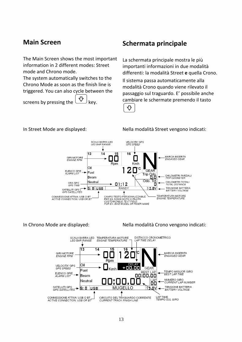
Main S The Main informatiomode andThe systemChrono Mtriggered.
screens by In Street M
In Chrono
creen
Screen shoon in 2 diffd Chrono mm automat
Mode as soo You can a
y pressing
Mode are d
o Mode are
ows the mferent modmode. tically switon as the flso cycle b
the
displayed:
e displayed
ost importdes: Street
tches to theinish line isbetween th
key.
d:
13
tant
e s he
Sch La scimpodiffeIl sismodpasscam
Nell
Nell
hermata
chermata portanti infoerenti: la mstema passdalità Cronsaggio sul tbiare le sc
a modalità
a modalità
a princip
principale ormazioni modalità Stsa automato quando vtraguardo. hermate p
à Street ven
à Crono ven
pale
mostra le pin due modreet e queticamente viene rilevE’ possibil
premendo i
ngono indi
ngono indi
più dalità lla Crono.alla ato il e anche il tasto
cati:
cati:
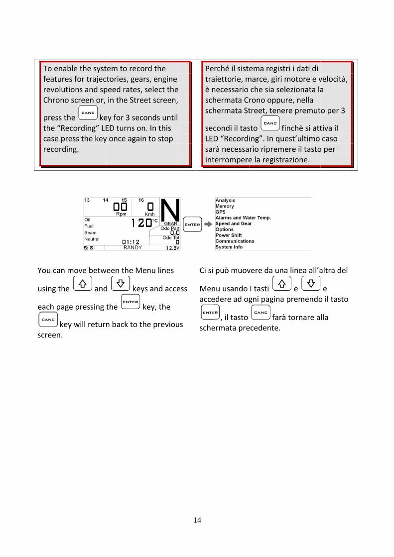
To enabfeaturesrevolutioChrono
press ththe “Reccase prerecordin
You can m
using the
each page
keyscreen.
le the systs for trajectons and spscreen or,
e kecording” LEess the keyng.
move betw
and
e pressing t
y will return
em to recotories, geapeed rates,in the Stre
ey for 3 secED turns on once agai
een the M
d key
the
n back to t
ord the ars, engine select theeet screen,
conds until n. In this n to stop
enu lines
ys and acce
key, the
he previou
14
e
Petraè nschsch
secLEsarint
ess
us
Ci si
Menacce
sche
rché il sisteaiettorie, mnecessario hermata Crhermata St
condi il tasD “Recordirà necessaterrompere
può muov
nu usando edere ad og
, il tasto ermata pre
ema registmarce, giri mche sia selrono opputreet, tene
sto fiing”. In querio ripremee la registr
vere da una
I tasti gni pagina
faràecedente.
tri i dati di motore e vlezionata lare, nella ere premut
inchè si attest’ultimo ere il tastoazione.
a linea all’a
e premendo
à tornare a
velocità, a
o per 3
tiva il caso
o per
altra del
e o il tasto
lla

15
Setting the engine RPM reading parameters If the DaVinci is displaying more or less than the correct engine RPM you just need to set the number of impulses received for each engine revolution:
Impostazione dei parametri di lettura RPM Se DaVinci indica più o meno giri rispetto al corretto valore RPM è sufficiente inserire il numero di impulsi ricevuti per ogni giro del motore:
Setting the distance reading parameters To be able to indicate the correct distance DaVinci needs two fundamental informations:
A. The circumference of the wheel (in millimeters) on which the sensor is mounted.
Impostazione dei parametri di lettura dei chilometri percorsi Per essere in grado di indicare la distanza percorsa DaVinci ha bisogno di due informazioni fondamentali:
A. La circonferenza della ruota (espressa in millimetri) sulla quale è montato il sensore.

16
B. Number of impulses (for example,
bolts of the brake disk read by the speed sensor) for each wheel turn. Once set the correct circumference you can find out the correct pulse number by trying different values and comparing the speed shown by DaVinci with the speed shown by the factory instruments at the specific engine speed.
B. Il numero di impulsi (ad esempio ibulloni del disco del freno rilevati dal sensore velocità) per ogni giro della ruota. Una volta impostata la corretta circonferenza potete trovare il giusto numero di impulsi provando differenti valori e paragonando la velocità mostrata da DaVinci con quella indicata dal tachimetro originale ad un determinato regime.
It’s also possible to acquire automatically the pulse number by using the Pulse Learning feature:
E’ anche possibile acquisire in automatico il numero di impulsi per ogni giro ruota utilizzando la funzione Pulse Learning:

Once entejust maderevolution
keyIMPORTAin order torevolutionmake morLearning fincrementdirection. Setting thNEUTRAL:
1. As s
ered the Pue to make an and confi
y. NT: createo make a cn without ore than 360from the bted indipe
he Warnin
shown on t
ulse Learnia completeirm the val
e a marker complete woverpassin0° repete teginning fondently by
ng Lights
the instruc
ing mode ye wheel lue with th
on the whwheel g 360°, if ythe Pulse or the valuy the rotati
ctions on th
17
you
he
eel
you
ue is on
UnaLeargiro
valoIMPruotsenzpiù dprinaumrota
ImpFOLL
he 1
volta entrrning è suffcompleto
re con il taORTANTE:ta in modoza superaredi 360° ripecipio in qu
mentato indzione della
postazioneLE:
1. Come m
rati nella mficiente esedella ruota
asto creare un da eseguie i 360°, in etere il Pulanto il valodipendentea ruota.
e delle Spi
mostrato da
modalità di eguire a ma e conferm
. riferimentre un giro caso si eselse Learninore viene emente da
ie
alle istruzio
Pulse ano un mare il
to sulla completo eguissero ng dal
l senso di
oni sullo

scr
possecthr
2. Engthe
OIL:
1. As
scrin wbikand
andsetfewsomturand
een put th
sition and conds to sereshold.
gage a geae LIGHT OF
shown on reen put thwhich the okes it’s enod leave the
d press t the LIGHTw bikes youme oil till trns on and d set the L
he gear in n
press et the LIGH
r and presFF threshol
the instruche bike in toil alarm isugh to ture engine no
duringT ON threshu will needhe factory then plug IGHT ON th
neutral
during 2HT ON
s to d.
ctions on the conditios on, for mn on the keot running,
2 secondshold. On a to take awoil alarm lthe DaVinchreshold.
18
2
set 2
OLIO
the on any ey ,
s to
way ight ci in
1
scherm
psoglia dspia.
2. Inserireper 2 sedi spegnspia.
O:
1. Come mschermcondiziodell’oliosufficienmanten
premerimpostaLIGHT Onecessaoriginal
o mettere
per 2 seconi accension
e una marcecondi per nimento “L
mostrato dao mettere one di acceo, per moltnte girare nere il moto
e peare la sogliON. Su alcuario togliere non si ac
in folle e p
ndi per impne (LIGHT O
ia e premeimpostareLIGHT OFF”
alle istruziola moto inensione dete moto è la chiave eore spento
er 2 seconda di accensune moto sre olio finchccende e p
premere
postare la ON) della
ere e la soglia ” della
oni sullo n ella spia
e o, e
di per sione sarà hè la spia oi

2. Adsim
pre
FUEL:
1. As scrit iwa
senduON
2. Fill
woto s
d the oil if mply run th
ess t
shown on reen take an fuel reseait 1 minute
nsor timer ring 2 secoN threshold the tank w
on’t be in reset the LIG
you took ie engine in
to set the
the instruaway someerve, turn oe in order t
go on andonds to setd. with fuel to
eserve andGHT OFF.
t away or n idle and
e LIGHT OF
ctions on te fuel to leaon the key,to let the f
press t the LIGHT
o be sure it
d press
19
F. 2
CAR
the ave , fuel
T
t
2
collegarsoglia L
2. Aggiungsemplic
in folle secondispegnim
BURANTE:
1. Come mschermlasciarechiave,che il s
si attivisecondaccens
2. Riempiressere s
e premeimpostaLIGHT O
re DaVinci IGHT ON. gere olio secemente ac
e premerei per imposmento LIGH
mostrato dmo togliere e la moto i, aspettareensore ben
i e premerdi per impoione LIGHTre il serbatsicuri di no
ere are la sogliOFF.
e imposta
e è stato toccendere il
e perstare la sogHT OFF.
dalle istruzcarburantn riserva, ge 1 minuto nzina temp
e postare la soT ON. oio in modon essere in
per 2 secoa di spegn
re la
olto o l motore
r 2 glia di
ioni sullo te per girare la in modo porizzato
er 2 oglia di
do da n riserva
ndi per imento

LIGHTS:
1. As showscreen tur
duON thresh
2. Turn OFduring
Setting th The coolenon‐lineafor each bpredefinecommon m
wn on the irn ON the
ring 2 secohold.
FF the bea2 seconds
he Cooler
r temperatr signal thabrand. On Ded temperamotorbike
instructionbeam light
onds to set
m light andto set the
Tempera
ture sensoat can be vDaVinci yoature maps brands:
ns on the t and press
t the LIGHT
d press LIGHT OFF
ature read
or generatevery differeu can load s for the m
20
ABB
s
T
F.
ding
es a ent
ost
1
2
ImpTem Il serefrigeneessesensmaputiliz
AGLIANTI:
1. Come mscherm
e premeimpostaLIGHT O
2. Spegne
psoglia d
postazionemperatura
nsore temigerante, aera un segnere molto dsore. In DaVppe di segnzzate dalle
mostrato dao accende
ere are la sogliON. re i fari ab
per 2 seconi spegnime
e della lett Liquido R
peratura dl variare dnale non lidiverso in fVinci sononale tempee più diffuse
alle istruziore i fari ab
per 2 secoa di accens
baglianti e
ndi per impento LIGHT
tura di Refrigeran
del liquido ella tempeneare che funzione de richiamaberatura solie marche d
oni sullo baglianti
ondi per sione
premere
postare la T OFF.
nte
eratura, può el tipo di bili le itamente di moto:

21
If you install the Starlane temperature sensor (code CH2OM10) you will need to select the STARLANE profile in the sensor list.
Se avete installato il sensore temperatura Starlane (codice CH2OM10) dovrà essere selezionato il profilo STARLANE nella lista dei sensori.
22
Updating the DaVinci firmware The software installed inside DaVinci and intended to manage all functionalities is referred to as Firmware. You can update the Firmware when new versions with additional implementations and/or improvements are made available by Starlane.
Aggiornamento del firmware di DaVinci Il software installato all’interno di DaVinci e che ne gestisce tutte le funzionalità ha il nome di Firmware. È possibile aggiornare il Firmware quando ne siano rese disponibili da Starlane nuove versioni con implementazioni aggiuntive e/o migliorie.
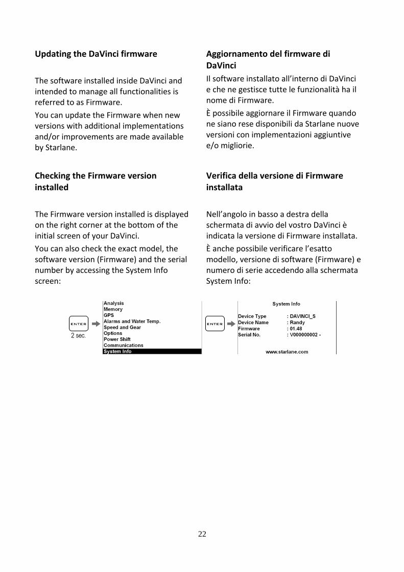
Checking the Firmware version installed The Firmware version installed is displayed on the right corner at the bottom of the initial screen of your DaVinci.
Verifica della versione di Firmware installata Nell’angolo in basso a destra della schermata di avvio del vostro DaVinci è indicata la versione di Firmware installata.
You can also check the exact model, the software version (Firmware) and the serial number by accessing the System Info screen:
È anche possibile verificare l’esatto modello, versione di software (Firmware) e numero di serie accedendo alla schermata System Info:
23
Downloading the update
Check on the technical support page of the www.starlane.com web site whether more up‐to‐date Firmware or DigiRace versions (the version number is higher) are available for your device. Follow the procedure described by the DigiRace software manual to download and install the latest Firmware update.
Scarico dell’aggiornamento
Verificare sulla pagina di supporto tecnico del sito www.starlane.com la disponibilità di versioni più aggiornate (numero di versione più alto) del Firmware per il vostro dispositivo nonché la relativa versione aggiornata di DigiRace. Seguire la procedura indicata sul manuale del software DigiRace per eseguire correttamente l’aggiornamento all’ultima versione di Firmware.
GPS signal acquisition
The first time the system is switched on after a long time or at a considerable distance from the previous place of operation it might require some minutes to find out the satellites and calculate its position, this phase is called “Cold Start”.
The next time the system will be used in the same location it will find out the satellites quickly and you will be able to operate immediately by entering the track within just a few seconds.
To provide for a correct and rapid acquisition before usage, it’s important to install DaVinci in the open where it can easily “see” a good portion of the sky.
Acquisizione del segnale GPS
La prima volta che il sistema viene acceso dopo un lungo periodo o a distanza considerevole dal luogo di utilizzo precedente potrebbe richiedere alcuni minuti per individuare i satelliti e calcolare la propria posizione, questa fase viene chiamata “Avvio a Freddo”.
La volta successiva che il sistema sarà utilizzato nello stesso luogo, esso individuerà i satelliti rapidamente e sarà possibile procedere immediatamente, entrando in pista entro pochi secondi.
Per consentire una rapida e corretta acquisizione prima dell’uso è importante posizionare DaVinci all’aperto dove possa “vedere” un buona porzione di cielo.

24
Configuration Setting the Freeze Time
You can set the lap time you wish to remain on the display when the lap is over (Freeze Time).
Carry out the following operations to set the Freeze Time:
Configurazione Impostazione del tempo di visualizzazione a fine giro
È possibile impostare il tempo per cui resta fissa sul display l’indicazione del giro appena concluso (Freeze Time).
Eseguire le seguenti operazioni per impostare il Freeze Time:

25
Aligning the GPS clock to the local timezone
DaVinci receives the Greenwich time from the GPS system satellites, it’s necessary to set the difference between the local time and the Greenwich one. Carry out the following operations to set the parameter:
Allineamento dell’orologio GPS con il fuso orario
DaVinci riceve l’ora di Greenwich dai satelliti del sistema GPS, è quindi necessario impostare la differenza tra l’ora locale e l’orario di Greenwich. Eseguire le seguenti operazioni per impostare il parametro:

26
Setting the LED Bar full scale
You can select the maximum speed rate of the LED Bar according to the features of the engine. Carry out the following operations to set the full scale:
Impostazione del fondo scala della Barra LED
E’ possibile selezionare il regime massimo della Barra LED in funzione delle caratteristiche del motore. Eseguire le seguenti operazioni per impostare il fondo scala:

27
Choosing LED Bar type
The LED Bar can be set in the following modes:
1. SHIFT LIGHT: the LED Bar is off and only the Shift Light is active.
2. SINGLE LED: only one LED turns on to give the “cursor” effect.
3. FULL LED: the LED Bar turns on progressively.
4. OFF: the LED Bar is totally off.
Carry out the following operations to set the mode:
Scelta del tipo di Barra LED
E’ possibile impostare la Barra LED nei seguenti modi:
1. SHIFT LIGHT: la Barra LED resta spenta ed è attivo solo il Flash di fuori giri.
2. SINGLE LED: si illumina un singolo LED che dà l’effetto “lancetta”.
3. FULL LED: la Barra si illumina progressivamente.
4. OFF: la Barra LED resta completamente spenta.
Eseguire le seguenti operazioni per impostare la modalità:

28
Setting the Shift LightCarry out the following operations to set the threshold:
Impostazione del Flash di fuori giriEseguire le seguenti operazioni per impostare il regime di accensione:
Selection of the units of measurement
Carry out the following operations to set the units of measurement:
Selezione delle unità di misura
Eseguire le seguenti operazioni per impostare le unità di misura:

29
Gear programming DaVinci can specify the gear you have engaged by calculating the continuous ratio between the engine speed and the wheel speed. • Make sure that you have connected
the wire intended to read the engine speed
• Make sure that the speed reading wire is connected with the wire intended to signal the vehicle speed, from the speed sensor to the connector of the original instrument panel or the Engine Control Unit (this sensor is usually arranged on one of the two wheels or at the output of the gear case).
If the vehicle is not equipped with a speed sensor, but the value is transmitted to the tachometer by means of a mechanical string, you can mount the optional Speed Kit (code CSKNP) intended to detect the bolts on the brake disc as soon as they pass by the sensor. To enable DaVinci to recognize the gears, set the number of engine gears and program the system after having arranged the motorbike on a stand keeping the rear wheel up (if the speed sensor is intended to detect the speed of the rear wheel) or while running it on the road (if the speed sensor is intended to detect the speed of the front wheel). To program the recognition of the gears properly, carry out the following operations:
Programmazione delle marce DaVinci è in grado di indicare la marcia inserita calcolando il continuo rapporto tra il regime motore e la velocità della ruota. • Accertarsi di aver collegato il filo di
lettura del regime motore • Accertarsi che il filo di lettura della
velocità sia collegato a quello di segnale della velocità del veicolo che va dal sensore velocità al connettore del pannello strumenti originale o alla Centralina Gestione Motore (tale sensore è solitamente posizionato su una delle due ruote o in uscita dalla scatola del cambio).
Se il veicolo non è dotato di un sensore velocità ma il valore è trasmesso al tachimetro tramite cordina meccanica potete montare il kit opzionale Speed Kit (codice CSKNP) che rileva i bulloni sul disco del freno quando questi passano davanti al sensore. Perché DaVinci riconosca le marce è necessario impostare il numero di marce del motore e programmare il sistema con la moto su un cavalletto che mantenga sollevata la ruota posteriore (se il sensore velocità rileva la velocità della ruota posteriore) o in strada (se il sensore velocità rileva la velocità della ruota anteriore). Per programmare correttamente il riconoscimento delle marce eseguire le seguenti operazioni:
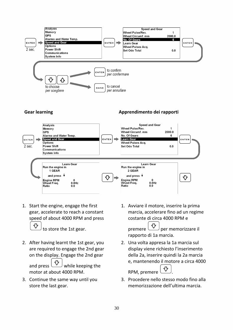
Gear lea
1. Start t
gear, aspeed
2. After hare reqon the
and prmotor
3. Continstore t
rning
he engine,accelerate of about 4
to store th
having learquired to ee display. E
ress at about 4nue the samthe last gea
, engage thto reach a 4000 RPM a
he 1st gear
rnt the 1st engage thengage the
while keep4000 RPM.me way unar.
he first constant and press
r.
gear, you e 2nd gear 2nd gear
ping the til you
30
App
1.
2.
3.
prendimen
Avviare il marcia, accostante d
premere rapporto Una voltadisplay viedella 2a, ie, manten
RPM, preProcederememorizz
nto dei rap
motore, inccelerare fdi circa 400
per di 1a marca appresa laene richiesinserire qunendo il m
mere e nello steszazione de
porti
nserire la pfino ad un 00 RPM e
memorizzacia. a 1a marcisto l’inserimindi la 2a motore a cir
. sso modo fll’ultima m
prima regime
are il
a sul mento marcia rca 4000
fino alla marcia.

Please Nas stablelearningrecommbrake slireduce dminimum
Note: ReconstantbetweenSPEED. Achange tgear to idisplay.
Setting th
You can scurrent vthe follow
The trip ofrom the
key
Note: Sincee as possibg cycle on tmended to pightly durindrive oscillm.
emember ttly calculatn ENGINE RAny action this ratio ainstantly a
he odome
set the totvehicle milwing oper
odometer main scre
y.
e the gear mble during the stand, ipress the rng storageations to a
that DaVinte the ratioREVOLUTIOon the clu
and cause appear on t
eter
tal odomeleage by cations:
can be queen by pre
must be the it is rear so as to a
ci will o ONS and utch may a false he
eter to thecarrying ou
uickly reseessing the
31
Nsrcfrmmt
NcMintaisc
e ut
Imp
E’ pdel veseg
et Il covelo
prin
N.B.: Poichéul cavallettapporto piconsiglia di reno postememorizzazminimo le orasmission
Nota: RicorcontinuameMOTORE e ntervento ale rapporstantaneamcorretta sul
postazione
ossibile imveicolo neguendo le
ontachilomocemente
ncipale pre
é durante to è necesiù stabile ppremere leriore durazione in moscillazionine.
rdarsi che Dente il rappVELOCITAsulla frizioto e far apmente unal display.
e del cont
mpostare iel contach seguenti
metri parziazzerato
emendo il
l’apprendisario averepossibile si eggermenante la odo da rid della
DaVinci calporto tra G’ e ogni ne può campparire marcia no
achilomet
i chilomethilometri toperazion
iale può edalla sche
tasto
mento e un
te il
urre al
cola GIRI
mbiare
on
tri
tri attuali otale ni:
ssere ermata
.

32
Quick shifter feature (only on DaVinci‐SX) DaVinci‐SX fits the built in Power Shift NRG unit based on a sensor that can detect the energy produced by the driver’s action on the gears lever. Installation 1. Remove the original bolt intended to
fasten the lever and replace it with the one supplied in the kit. In case of assembly on the transmission rod, unscrew the uniball and insert the sensor, as it is shown by the figure.
2. According to the vehicle leverage, install the sensor, as it is shown by the figure by always placing the two supplied washers in‐between. The sensor direction and orientation represent no decisive factor.
Funzione di cambio elettronico (solo su DaVinci‐SX) DaVinci‐SX è dotato di cambio elettronico Power Shift NRG integrato che basa il suo funzionamento su un sensore in grado di rilevare l’energia generata dall’azione del pilota sulla leva del cambio. Installazione 1. Rimuovere il bullone originale di
fissaggio della leva e sostituirlo con quello fornito nel kit. In caso di montaggio sull’asta di rinvio, svitare l’uniball e inserire il sensore come indicato in figura.
2. A seconda del leveraggio del veicolo, installare il sensore come indicato in figura interponendo sempre le due rondelle fornite, non sono determinanti il verso e l’orientamento del sensore.
ROADRACING ‐ MOTO VELOCITA’
DIRECT LEVER – LEVA DIRETTA
SOCKET HEAD SCREW LEVER
LEVA CON SEDE VITE A BRUGOLA KTM LEVER – LEVA KTM
33
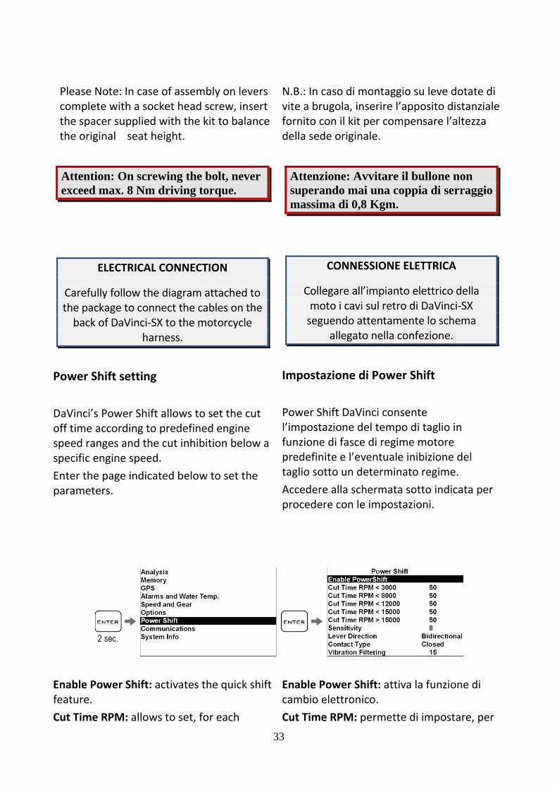
Please Note: In case of assembly on levers complete with a socket head screw, insert the spacer supplied with the kit to balance the original seat height.
Attention: On screwing the bolt, never exceed max. 8 Nm driving torque.
ELECTRICAL CONNECTION
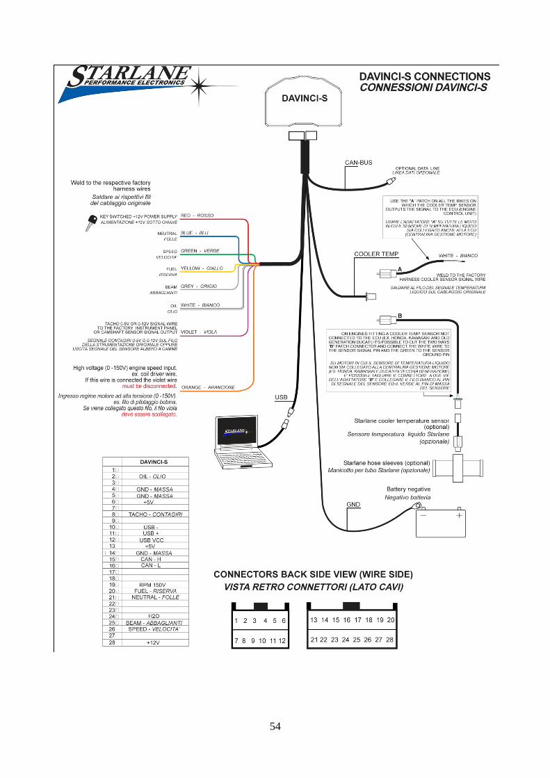
Carefully follow the diagram attached to the package to connect the cables on the back of DaVinci‐SX to the motorcycle
harness.
Power Shift setting DaVinci’s Power Shift allows to set the cut off time according to predefined engine speed ranges and the cut inhibition below a specific engine speed. Enter the page indicated below to set the parameters.
N.B.: In caso di montaggio su leve dotate di vite a brugola, inserire l’apposito distanziale fornito con il kit per compensare l’altezza della sede originale.
Attenzione: Avvitare il bullone non superando mai una coppia di serraggio massima di 0,8 Kgm.
CONNESSIONE ELETTRICA
Collegare all’impianto elettrico della moto i cavi sul retro di DaVinci‐SX seguendo attentamente lo schema
allegato nella confezione.
Impostazione di Power Shift Power Shift DaVinci consente l’impostazione del tempo di taglio in funzione di fasce di regime motore predefinite e l’eventuale inibizione del taglio sotto un determinato regime. Accedere alla schermata sotto indicata per procedere con le impostazioni.
Enable Power Shift: activates the quick shift feature. Cut Time RPM: allows to set, for each
Enable Power Shift: attiva la funzione di cambio elettronico. Cut Time RPM: permette di impostare, per
34
range, the desired cut off time in milliseconds (default value: 50). You can set to 0 the value on the first range to inhibit the cut off below 3000 RPM. Sensitivity: allows to set the sensor cut off threshold. See below for detailed instructions. Lever Direction: allows to set the direction of operation (default and surely suggested: Bidirectional). See below for detailed instructions. Contact Type: defines the kind of electrical contact output (default: Closed). See connection diagram and indications below. Vibration Filtering: in case of undesired cuts due to strong vibrations of the foot rest or of the lever you can increase the filter value (default value: 15). Setting the cut off threshold The force at which you wish the system to cut off can be set on 20 steps, the minimum value (high sensitivity) is indicated by ”1”, setting a higher value will result in a stickly behaviour of the lever till the maximum value reached on the ”20” position.
Direction of operation Power Shift NRG can be easily used without requiring any special setup. It can detect the signal in both directions of operation of the lever. When set up by default, Power Shift will act at the time of engaging or shifting the gears (please remember that – when shifting the gears ‐ the action of the electronic gears has no effect on the engagement thereof). However, you can
ogni fascia di giri, il tempo di taglio desiderato in millisecondi (valore predefinito: 50). E’ possibile impostare a 0 il valore sulla prima fascia per inibire il taglio sotto i 3000 RPM. Sensitivity: permette di impostare la soglia di intervento del sensore. Vedere sotto per istruzioni dettagliate. Lever Direction: permette di impostare il verso di funzionamento (predefinito e sicuramente consigliato: Bidirezionale). Vedere sotto per istruzioni dettagliate. Contact Type: definisce il tipo di contatto elettrico del pilotaggio (predefinito: Chiuso). Vedere schema di connessione e indicazioni in basso. Vibration Filtering: in caso di tagli indesiderati dovuti a forti vibrazioni della pedana o della leva è possibile incrementare il valore di filtro (valore predefinito: 15). Taratura della soglia di intervento La soglia di energia alla quale si desidera che intervenga il taglio può essere impostata su 20 livelli, il valore minimo (più sensibile) è indicato con ”1”, aumentando il valore si aumenta l’energia richiesta dal pilota nella cambiata, il valore massimo (innesto più duro) è raggiunto nella posizione ”20”. Verso di funzionamento Per essere facilmente utilizzabile senza particolari tarature Power Shift NRG è in grado di rilevare il segnale in entrambi i versi di azionamento della leva, con l’impostazione di fabbrica Power Shift interverrà sia in inserimento che in scalata (ricordiamo che in scalata l’intervento del cambio elettronico non ha comunque effetto sull’innesto della marcia), è

35
limit the action to one of the two directions.
Lever direction notice The direction selection is strongly related to mechanical characteristics of each kind of lever or rod. Independently by your linkage allowing or not the correct unidirectional operating, it’s very important to set the sensitivity to the higher threshold working on your own vehicle, as stated on the “Setting the Sensitivity” paragraph, the sensitivity threshold must be set to the highest working value that still allows you the correct shifting. If the threshold is set to a very sensitive value the system will always cut in both directions.
Please Note: For a easier setting and a smoother operating it is recommended to keep the system set to the bidirectional
mode.
Setting the Sensitivity While the engine is off move by hand the gearshift lever, in upshift direction, till you feel the gear “sticking”, the “Best” LED must light on just while you are feeling the “stiffness”, if the LED keeps off you must reduce the Sensitivity value, if it lights on before the gear is engaged you must increase the value. The correct setting is reached when the LED lights on at the moment of the gear engaging.
VERY IMPORTANT: Please note that the value measured by the sensor depends upon the shift energy and not simply upon the force. As a consequence, a slow action on the lever
comunque possibile limitare l’intervento a una delle due direzioni.
Nota sul verso di funzionamento La selezione del verso è strettamente correlata alle caratteristiche meccaniche di ogni leva o asta. Indipendentemente dal fatto che la propria installazione consenta il corretto funzionamento della modalità monodirezionale, è di primaria importanza aver impostato la sensibilità della soglia d’intervento al valore più alto possibile per il proprio veicolo, come descritto nel paragrafo “Regolazione della sensibilità”. Se la soglia d’intervento è impostata ad un valore molto sensibile il sistema taglierà sempre in entrambi i versi.
N.B: Per una più semplice taratura e miglior fluidità di funzionamento è consigliato comunque mantenere il
sistema sulla modalità bidirezionale.
Regolazione della sensibilità A motore spento azionare con la mano la leva del cambio, nel senso di inserimento, fino a che si sente “puntare” la marcia, il LED “Best“ si attiverà non appena raggiunto tale “puntamento”, se il LED resta spento il valore di Sensitivity dovrà essere abbassato, se invece si attiva prima che la marcia punti dovrà essere aumentato. La taratura è corretta se il LED si attiva nell’esatto istante del “puntamento”.
MOLTO IMPORTANTE: Da notare che il valore rilevato dal sensore è in funzione dell’energia della cambiata e non semplicemente della forza, pertanto
36
may fail to be detected or it may produce a weaker signal compared to the driver’s usual action. This aspect shall be considered at the time of the setup (by means of a rapid and resolute movement of the lever as if you were driving) and by the driver who will resolutely shift the gears by releasing the gears lever after every single operation.
It’s suggested to optimize the setting after a drive test; in order to avoid the intervention being influenced by possible dumps, vibrations or unwanted actions by the rider ,the optimal setting is always reached looking for the highest value on the selector, set the sensitivity to increasing values till the force on the lever during the ride is too high, then lower the sensitivity value by 1 step. So its always necessary to opt for a higher threshold if you notice undesired cuts or possible gears coming out after a shifting.
If, after a correct sensitivity adjustment, while driving you can notice undesired cuts due to vibrations over a certain engine speed, you can increase the value of the Vibration Filtering.
Inverting the electric contact type (normally opened‐normally closed) Note: In the case it should be necessary to invert the cut contact, for particular applications as the installation on Ducati bikes, modify “Contact Type” parameter. (Attention: before making this operation verify the electrical connections because the contact inversion could damage the
un’azione lenta sulla leva può non essere rilevata o può generare un segnale più debole rispetto alla normale azione del pilota. Questo aspetto deve essere considerato sia in fase di taratura (con movimento della leva rapido e deciso come se si stesse guidando) sia dal pilota durante la guida che eseguirà cambiate decise rilasciando la leva del cambio dopo ogni azionamento.
E’ consigliabile ottimizzare la taratura dopo una prova su strada; per evitare che l’intervento sia influenzato da eventuali sobbalzi, vibrazioni o azioni involontarie del pilota , la taratura ottimale si ottiene cercando sempre il valore di durezza maggiore, impostare la Sensitivity a valori crescenti finché lo sforzo sulla leva durante la cambiata diventa eccessivo, dopodiché riabbassare il valore di Sensitivity di un 1 punto. E’ quindi necessario optare sempre per una soglia più alta se si notano tagli di corrente indesiderati o l’eventuale accidentale uscita di una marcia dopo la cambiata.
Se, dopo aver regolato correttamente la sensibilità, durante la guida si notano tagli indesiderati dovuti a vibrazioni oltre un certo regime, è possibile aumentare il valore del Vibration Filtering.
Inversione del contatto di azionamento (normalmente aperto‐normalmente chiuso) N.B: Nel caso in cui fosse necessario invertire il contatto di azionamento, per applicazioni particolari come l’installazione su moto Ducati , modificare il parametro “Contact Type”. (Attenzione: prima di effettuare tale

37
motorbike electronics, harness or some fuses). Please Note: If you reverse the operation contact when DaVinci is not supplied, the motorcycle might fail to start or power off as soon as you engage the gears. In this case, make sure that the DaVinci control unit is properly supplied.
operazione verificare le connessioni elettriche perché l’inversione del contatto potrebbe danneggiare l’impianto o i fusibili). Nota: Se viene effettuata l’inversione del contatto di azionamento, quando DaVinci non è alimentato la moto potrebbe non avviarsi o spegnersi all'innesto della marcia, in tal caso verificare che alla centralina DaVinci arrivi la corretta alimentazione.

38
Track management Learning the Finish Line and Intermediate positions
DaVinci internal laptimer is based on the GPS System so it's necessary to let it know the exact position of the Finish Line and the desired Intermediates. Once the positions have been acquired the chrono can start counting whenever you cross the Finish Line. Carry out the operations here below before entering a new track and set the positions during the first lap.
IMPORTANT! Before starting the learning procedure be sure that the system has been switched on in time to allow it acquire at least 5 satellites.
Gestione circuiti Apprendimento della linea di traguardo e degli intermedi
Il cronometro interno di DaVinci è basato sul sistema GPS, pertanto è necessario fornirgli l’esatta posizione del Traguardo e degli Intermedi desiderati. Una volta che le posizioni sono state acquisite il cronometro può iniziare il conteggio ogni volta che passate sulla linea del traguardo. Eseguite le operazioni indicate di seguito prima di entrare in un nuovo circuito e impostate le posizioni durante il primo giro.
IMPORTANTE! Prima di iniziare la procedura di apprendimento assicurarsi che il sistema sia stato acceso il tempo necessario all’acquisizione di almeno 5 satelliti.

39
The coordinates will be kept active till you set new positions for a different track.
Le coordinate saranno mantenute attive finché non saranno impostate nuove posizioni per un circuito differente.
Storing the coordinates of the Finish Line and Intermediate positions
Memorizzazione delle coordinate di Traguardo e Intermedi
Once you have learnt the position, you can store them in a list of 16 favourite Tracks.
Una volta che sono state apprese le posizioni è possibile memorizzarle in una lista di 16 circuiti favoriti.
40
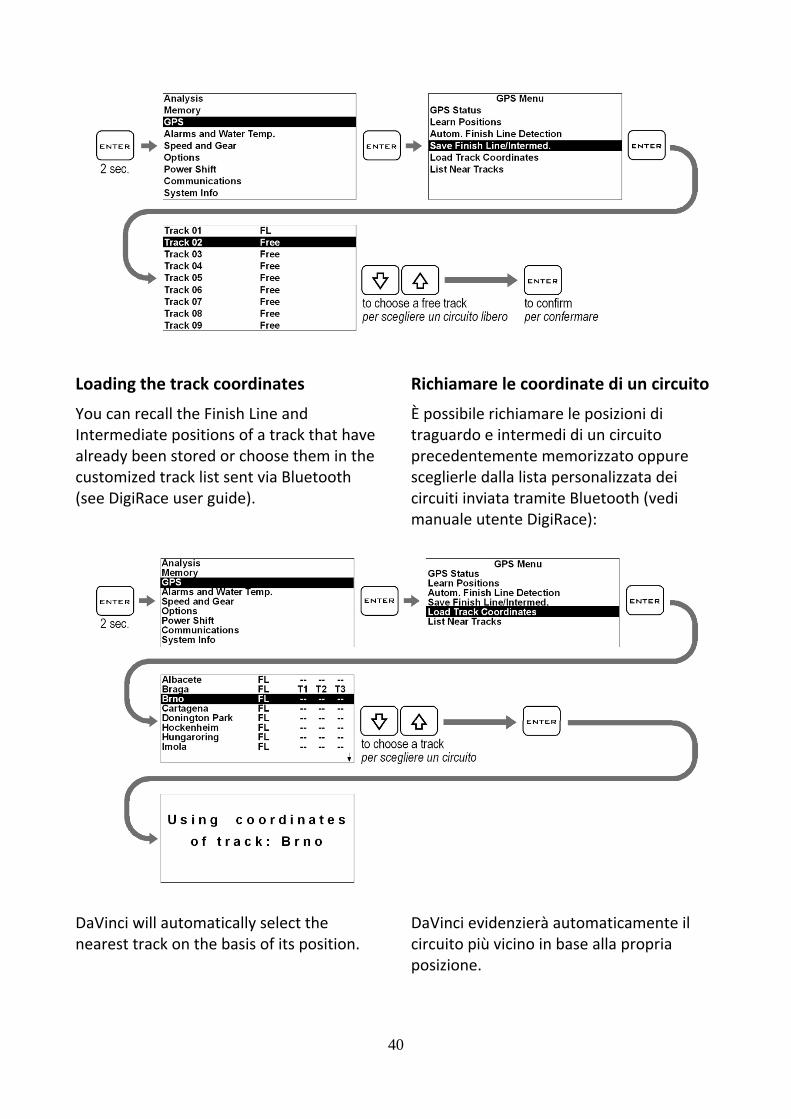
Loading the track coordinates
You can recall the Finish Line and Intermediate positions of a track that have already been stored or choose them in the customized track list sent via Bluetooth (see DigiRace user guide).
Richiamare le coordinate di un circuito
È possibile richiamare le posizioni di traguardo e intermedi di un circuito precedentemente memorizzato oppure sceglierle dalla lista personalizzata dei circuiti inviata tramite Bluetooth (vedi manuale utente DigiRace):
DaVinci will automatically select the nearest track on the basis of its position.
DaVinci evidenzierà automaticamente il circuito più vicino in base alla propria posizione.

41
Analysis of the stored times DaVinci stores the times of 999 laps divided into 99 sessions. Carry out the following operations to display the stored times:
Analisi dei tempi memorizzati DaVinci memorizza i tempi di 999 giri suddivisi in 99 sessioni. Eseguire le seguenti operazioni per visualizzare i tempi memorizzati:

42
Managing the Hour Meters
In order to allow an easy and sharp engine maintenance DaVinci also integrates two separate Hour Meters. The Hour Meters are activated by the engine speed signal and by the GPS speed.Carry out the following operations to check the Hour Meters:
Gestione dei Contaore
Per consentire una semplice e puntuale manutenzione del motore DaVinci integra anche due Contaore separati. I Contaore sono attivati sia dal segnale regime motore che dalla velocità GPS. Eseguire le seguenti operazioni per controllare i Contaore:
Resetting the Hour Meters
Carry out the following operations to reset the Hour Meters:
Azzeramento dei Contaore
Eseguire le seguenti operazioni per azzerare i Contaore:

MemorSession re
The devicrecording engine spGPS speedfor at leasRecordingengine spspeed is bleast 5 sec
To recorselect th
the
You can m
just by ho2 seconds
While DaVblinks at tREC LED li
NOTE: inof uselesautomatbelow 1
ry Manaecording
e will autoa new seseed goes od goes ovest 2 secs. g will automeed is = 0 rbelow 10 Kcs.
rd the sesshe Chrono
key.
manually st
olding the s.
Vinci is recthe bottomights on.
n order to vss sessionstically everminute.
agemen
omatically ssion whenover 3000 rr 25 Km/h
matically strpm and thm/h (6.2 m
ion automscreen by
tart and sto
butto
ording them of the scr
void the ms, DaVinci dry session o
nt
start ever the rpm or the(15.5 mph
top if the he GPS mph) for at
atically, pressing
op recordin
on down fo
e REC label reen and th
memorizatiodeletes of duration
43
e h)
ng
or
GeRe
Il dautvoRPalmLa se GPsec
Pas
ta
È pma
pe
he
on
n
MenREC acce
NOmecanregmi
estione gistrazione
dispositivo tomaticamlta che il reM o la velomeno 2 secregistrazioil regime mPS è inferiocondi.
Perché le seautomaticaelezionare
asto
possibile atanualment
r 2 second
ntre DaVinclampeggiaende il led
OTA: per evemorizzatencella autogistrazionenuto.
della me delle ses
cominceràmente una egime motocità GPS scondi. one si fermmotore scere a 10 Km
essioni venamente è ne la scherm
.
ttivare e fee la registr
i il tasto
ci è in regisa alla base REC.
vitare che ve sessioni inomaticamee di durata
memoriassioni
à a registranuova sessore superasupera i 25
ma automatende a 0 e m/h per alm
ngano regisnecessario mata Crono
ermare razione pre
.
strazione ldel display
vengano nutili, DaVente ogni inferiore a
a
are sione ogni a i 3000 5 Km/h per
ticamente la velocità meno 5
strate
con il
emendo
a scritta y e si
inci
a 1
44
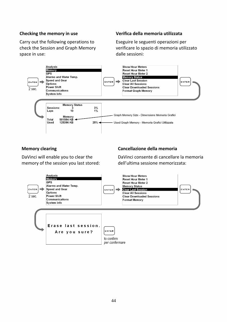
Checking the memory in use
Carry out the following operations to check the Session and Graph Memory space in use:
Verifica della memoria utilizzata
Eseguire le seguenti operazioni per verificare lo spazio di memoria utilizzato dalle sessioni:
Memory clearing
DaVinci will enable you to clear the memory of the session you last stored:
Cancellazione della memoria
DaVinci consente di cancellare la memoria dell’ultima sessione memorizzata:

45
or the complete session list: oppure di tutta la lista di sessioni:
Memory Formatting
You can completely format the DaVinci Memory by executing the following operations:
Formattazione della Memoria
È possibile formattare totalmente la Memoria di DaVinci eseguendo le operazioni indicate di seguito:
Attention: if you format the memory all the operation parameters will be reset and you’ll have to set them up again or to send the instrument your own file with the parameters you have set up before from the PC. It is recommended to import the parameters in DigiRace‐MMX and to save them on a file before formatting.
Attenzione: se si esegue la formattazione della memoria tutti i parametri di funzionamento saranno resettati e sarà necessario reimpostarli o inviare allo strumento dal PC il proprio file con i parametri precedentemente impostati. E’ quindi consigliato importare i parametri in DigiRace‐MMX e salvarli su file prima di eseguire la formattazione.

46
If you only wish to clear the Memory of the Sessions you have already downloaded, you can do it by using the Clear Downloaded Sessions command:
Se si vuole cancellare solo la Memoria delle Sessioni già scaricate è possibile farlo con il comando Clear Downloaded Sessions:
47
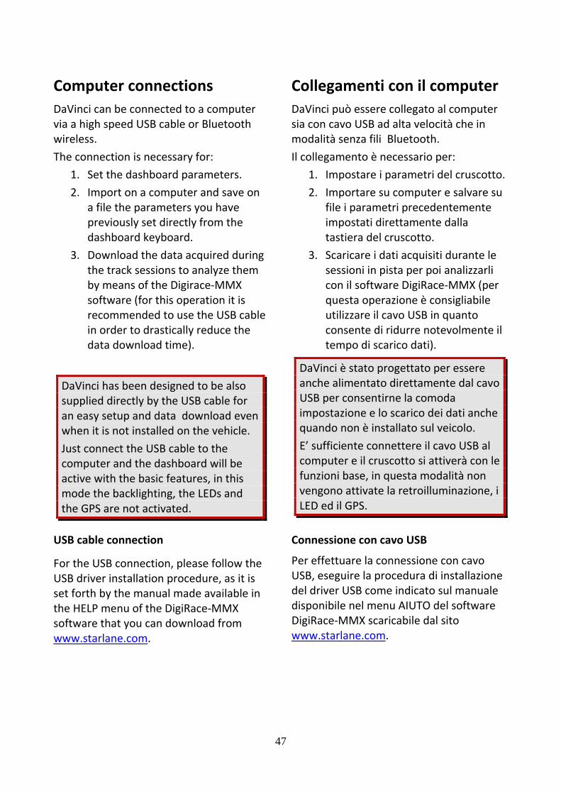
Computer connections DaVinci can be connected to a computer via a high speed USB cable or Bluetooth wireless. The connection is necessary for:
1. Set the dashboard parameters. 2. Import on a computer and save on
a file the parameters you have previously set directly from the dashboard keyboard.
3. Download the data acquired during the track sessions to analyze them by means of the Digirace‐MMX software (for this operation it is recommended to use the USB cable in order to drastically reduce the data download time).
DaVinci has been designed to be also supplied directly by the USB cable for an easy setup and data download even when it is not installed on the vehicle. Just connect the USB cable to the computer and the dashboard will be active with the basic features, in this mode the backlighting, the LEDs and the GPS are not activated.
Collegamenti con il computerDaVinci può essere collegato al computer sia con cavo USB ad alta velocità che in modalità senza fili Bluetooth. Il collegamento è necessario per:
1. Impostare i parametri del cruscotto.2. Importare su computer e salvare su
file i parametri precedentemente impostati direttamente dalla tastiera del cruscotto.
3. Scaricare i dati acquisiti durante le sessioni in pista per poi analizzarli con il software DigiRace‐MMX (per questa operazione è consigliabile utilizzare il cavo USB in quanto consente di ridurre notevolmente il tempo di scarico dati).
DaVinci è stato progettato per essere anche alimentato direttamente dal cavo USB per consentirne la comoda impostazione e lo scarico dei dati anche quando non è installato sul veicolo. E’ sufficiente connettere il cavo USB al computer e il cruscotto si attiverà con le funzioni base, in questa modalità non vengono attivate la retroilluminazione, i LED ed il GPS.
USB cable connection
For the USB connection, please follow the USB driver installation procedure, as it is set forth by the manual made available in the HELP menu of the DigiRace‐MMX software that you can download from www.starlane.com.
Connessione con cavo USB
Per effettuare la connessione con cavo USB, eseguire la procedura di installazione del driver USB come indicato sul manuale disponibile nel menu AIUTO del software DigiRace‐MMX scaricabile dal sito www.starlane.com.

48
When the USB cable is plug into the PC, DaVinci will be seen as a normal USB flash memory unit, in order to avoid any malfunction, never copy or remove any file manually on the DaVinci removable unit.
Configuring the Bluetooth connection
To activate the Bluetooth communication between PC and device proceed as follows: 1. Install the drivers supplied by the
manufacturer of the Bluetooth device.2. Power on DaVinci and keep it not more
than 2‐3 metres from the PC.
3. Click on the Bluetooth icon in the Windows® notification area and select the "Add a Bluetooth Device" item to start searching for visible Bluetooth devices.
Quando il cavo USB viene collegato al computer, DaVinci viene visto come una normale memoria flash USB, onde evitare anomalie nel funzionamento è importante non copiare o rimuovere mai alcun file manualmente dall’unità removibile DaVinci.
Impostazione della connessione Bluetooth
Per attivare la comunicazione Bluetooth tra il PC e lo strumento procedere come segue: 1. Installare i driver forniti dal produttore
del dispositivo Bluetooth. 2. Accendere DaVinci e posizionarlo entro
2‐3 metri dal PC.
3. Cliccare sull'icona Bluetooth presente nell'area di notifica di Windows® e selezionare la voce "Aggiungi dispositivo Bluetooth" per attivare la ricerca dei dispositivi Bluetooth visibili.
4. From Add Bluetooth Device Wizard window select the checkbox "My device is set up and ready to be found" and click on the "Next" button to search for any Bluetooth device in the proximity.
4. Nella finestra della procedura guidata selezionare la casella "Il dispositivo è configurato ed è pronto per il rilevamento" e cliccare sul pulsante "Avanti" per effettuare una ricerca dei dispositivi Bluetooth presenti nelle vicinanze.

49
5. A new device will be found. It is specified by an abbreviation corresponding to the unique code (device address, e.g.: 00:04:3E:25:ab:14) of your DaVinci. The name DaVinci will appear on the display after some seconds. If no device is found out, try powering off and on DaVinci and click on the button "Search Again".
6. Select the device and click on the "Next" button.
7. Select the item "Use the passkey found
in the documentation", type the PIN in the box on the right and click on the "Next" button. The default PIN is 0000. If you do not remember the PIN, reset it as described in the following section and try again by using the default PIN (0000).
5. Verrà rilevato un nuovo dispositivo indicato con una sigla corrispondente al codice univoco (indirizzo dispositivo, es.: 00:04:3E:25:ab:14) del vostro DaVinci. Dopo alcuni secondi verrà visualizzato il nome DaVinci. Se il dispositivo non viene rilevato, provare a spegnere e riaccendere DaVinci e cliccare sul pulsante "Nuova Ricerca".
6. Selezionare il dispositivo e cliccare sul pulsante "Avanti".
7. Selezionare la voce "Utilizza la passkey
contenuta nella documentazione", digitare il PIN nella casella a destra e cliccare sul pulsante "Avanti". Il PIN di default è 0000. Se non vi ricordate il PIN, eseguire il reset del PIN come indicato nella sezione successiva e riprovare usando il PIN di default (0000).

50
8. If the pairing was successful, the
(serial) COM ports for the communication between the PC and the DaVinci device appear on the display. The port used by the DigiRace‐MMX software is the one named "Outgoing COM port" (COM8 in the example represented by the figure).
9. Click on the button "Finish" to quit the
pairing procedure.
8. Se l'accoppiamento ha avuto successo
vengono visualizzate le porte COM (seriali) utilizzate per la comunicazione tra il PC e il dispositivo DaVinci. La porta utilizzata dal software DigiRace‐MMX è quella denominata "Porta COM in uscita" (COM8 nell'esempio rappresentato in figura).
9. Cliccare sul pulsante "Fine" per
terminare la procedura di accoppiamento.

51
Protecting the Bluetooth ConnectionYour Bluetooth Manager will require a PIN during the pairing process. The default PIN is:0000. You can customise your PIN by following the procedure described by the user’s manual of the DigiRace software. If you forget your DaVinci PIN you can reset it to the default value by executing the following operations:
Protezione della Connessione Bluetooth Il vostro Bluetooth Manager richiederà il PIN durante la fase di accoppiamento del dispositivo (Pairing).Il PIN di default è: 0000. È possibile inserire un PIN personalizzato seguendo la procedura illustrata sul manuale utente del software DigiRace. In caso vi dimentichiate il PIN del vostro DaVinci è possibile resettarlo al valore di default eseguendo la seguente procedura:
After the PIN reset, power on DaVinciagain.
Attention: whenever you modify the PIN, provide once again for pairing with the PC.
Al termine del reset del PIN riaccendere DaVinci.
Attenzione: ogni volta che viene modificato il PIN è necessario rieseguire l’accoppiamento (pairing) con il PC.
Cleaning the surfaces Use a soft cloth wetted with water to clean the surfaces of your DaVinci. Using alcohol or aggressive detergents might turn the transparent areas opaque.
Pulizia delle superfici Per pulire le superfici del vostro DaVinci usate un panno morbido bagnato con acqua, l’uso di alcool o detergenti aggressivi può opacizzare le aree trasparenti.

52
Warranty DaVinci is covered by a 12‐month warranty for all manufacturing defects.
Notes DaVinci is not type‐approved for road use.
GaranziaDaVinci è coperto da 12 mesi di garanzia sui difetti di fabbricazione.
Note DaVinci non è omologato per uso stradale.

NOTE: Formanual pl
User Guid
r any updalease visit twww.st
de Version:
te to the pthe web sitarlane.com
DVNS_00
present te: m
1.02
53
NOma
Ve
OTA: Eventanuale son
w
rsione Ma
24061 Al
uali aggioro disponibwww.starla
nuale: DVN
Via Madbano S. Ale
TF
e‐mail: http:/
rnamenti abili sul sito:ane.com
NS_001.02
Sta
donna dellessandro (Tel. +39 035Fax +39 035sales@sta//www.sta
l presente
arlane s.r.l.
e Rose, 70BG) ‐ Italia5‐45210075‐4528208arlane.comarlane.com
.
0 a 7 8 mm
54

55

56


