Download - Level 2 - Electric Vehicle Charging Station

Level 2 - Electric Vehicle Charging StationEVB16 (16A) - EVB30 (30A) - EVB40 (40A)
Installation Instructions
WARNINGS AND CAUTIONS:• TO AVOID FIRE, SHOCK, OR DEATH; TURN OFF POWER AT CIRCUIT BREAKER OR FUSE AND TEST THAT POWER IS OFF BEFORE WIRING!• Iftheinformationinthisinstructionsheetisnotfollowedexactly,SHOCK OR FIRE MAY RESULT CAUSING PROPERTY DAMAGE, PERSONAL INJURY OR DEATH.• Foroutdoorinstallations,hard-wireconnectionisrequired.TheEVSEhasawatertight(NEMA4)enclosurewhichhousescriticalelectronics.UseofUL-listedwatertightconduitcompressionfittingis
requiredtomaintainthewatertight(NEMA4)rating.Useelectrically-conductive,UL-listedthreadsealant(KOPR-SHIELD®)topreventwater/moisturefromenteringoraccumulatingwithinthebox,conduitbody,orfitting.PerNECArticle250,theconduitmusthavecontinuityfromthehubtotheserviceentrance.
• Hard-wireinstallationandservicemustbeperformedbyanelectrician.• IMPORTANT:Savetheseinstructionsforlocalelectricalinspector’suseandfuturereference. NOTE:Unitoperateson208Vor240Vcircuit,itwillnotoperateon120V.
PK-93980-10-00-0C
NOTE:ThePlug-InChargingStationmustbeinstalledwithaLevitonPre-WireKit(sold separately).FailuretodosomeansthestationnolongercomplieswithitsULlisting.Thelistingrequiresthestationberemovablewithouttools.RefertoPre-WireKitinstructionsfirstifamountinglocationhasnotbeenestablished.Ensurethatthecorrecttemplatewithinthepre-wirekitisused,asseveraltemplatesareavailablewithinthebox.ForEVB40installation,ensurethattheEVB40-5PTisusedforflushmountinstallation,andtheEVB40-SPTisusedforsurfacemountedinstallation.1. InstallPre-WireKit.ForEVB16,useInstallationKitEVK02;forEVB30andEVB40useInstallationKitEVK05.2. DepressreleasetabsonthebottomoftheChargingStation,andremoveChargingStationDoorbyliftingupwards(see Figure 2).3. LocatethefourMountingButtonsonthebackoftheChargingStation. LocatetheGuidePinSlotabovethePanelFastenerScrew(see Figure 1).4. AligntheGuidePinSlotwiththeGuidePinontheMountingBracket,andthefourMountingButtonswiththefourkeyholesontheMountingBracket.5. Oncealigned,gentlypresstheChargingStationontotheMountingBracket.6. AllowtheChargingStationtoslowlyslidedownintoplace.EnsureallfourMountingButtonsaresecuredineachkeyholeontheMountingBracketbeforereleasingtheChargingStation.7. TightenthePanelFastenerScrewtosecuretheChargingStationtotheMountingBracket(see Figure 2).Proceed to POWER CHARGING STATION section.
PLUG-IN INSTALLATION
ThankyouforpurchasingtheLevel2ElectricVehicleChargingStation.Thisinstallationsheetincludesthelatestinformationatthetimeofprinting.Levitonreservestherighttomakechangestothisproductwithoutfurthernotice.Changesormodificationstothisproductbyotherthananauthorizedserviceprovidercouldvoidtheproductwarranty.Ifyouhavequestionsabouttheuseofthisproduct,contactyourCustomerServiceRepresentative.RefertotheCustomerSupportsectionlocatedintheseinstructions.Important Notes to the Installer:•TheEVB40-5PTwithtopmountedplugisintendedforflushmountapplicationswheretheelectricalboxcanbe
recessedintothewall.•TheEVB40-SPTwithbottommountedplugisintendedforplug-insolidwallapplicationswheretheelectricalbox
mustbesurfacemountedonthewall.•TheEVB16andEVB30areonlyavailablewiththetop-mountedplug.• Plug-inChargingStationsmustbeinstalledwiththeuseofaLevitonPre-wirekit.ForInstallationoftheEVB16,use
LevitonInstallationKitEVK02;forInstallationoftheEVB30andEVB40,useInstallationKitEVK05. ReadallinstructionsbeforeinstallingtheMountingBracketandChargingStation.•Ensurethatthecorrecttemplateisusedforinstallation,asseveraltemplatesareavailablewithinthepre-wirekits.• Theinstallerisresponsibleforverifyingthatthewallstructure/surfacewillsafelysupportatotalloadof200lbs.• Observeallgoverningcodesandordinances.• Besuretoleavetheseinstructionswiththeconsumer.Important Notes to the Consumer:• EnsureyourChargingStationisinstalledbyanelectrician.• KeeptheseinstructionswithyourUserGuideforfuturereference.
INTRODUCTION
GuidePin Slot
GuidePin
Wall Stud
MountingButton (4)
Keyhole (4)
PanelFastener
Screw
Figure 1
MountingBracket
PanelFastener
Screw
Power Supply Plug location onEVB16, EVB30 and EVB40-5PT.
Wall Stud
Release Tab
Figure 2
GuidePin Slot
Power supply plug location on EVB40-SPT
MOUNTING LOCATION
TheChargingStationshouldbelocatedincloseproximitytotheelectricvehicle’sparkinglocation.TheChargingStationmustconnecttotheelectricvehicleviaaChargeConnectorandChargeConnectorCord.NOTE:ThepathfromtheChargingStationtotheelectricvehicleshouldbefreefromobstacles,andbewithintherangeoftheChargeConnectorCord(19footstandardlengthforEVB16,25footstandardlengthforEVB30,EVB40).TherecommendedmountingheightoftheChargingStationisnottoexceed48inches,butnotlessthan42inchesfromthefloortothetopoftheChargingStation.ThisprovidesconvenientaccessandoperationoftheChargingStation,andmeetsADArequirementsforaccess.NOTE:TheareasurroundingtheChargingStationenclosureshouldbefreefromobstruction.Recommendedclearancearoundstation:5inchesaboveand3-1/2inchesoneitherside.
RATINGS
120/208V60Hz3-phaseY(L1-G/L2-G-120V,L1-L2–208V)120/240V60HzSplit-phase(L1-G/L2-G-120V,L1-L2–240V)
16A (EVB16) - 30A (EVB30) - 40A (EVB40)
Voltage
Current
NOTE:ChargingStationoperateson120/208Vor120/240Vcircuitonly.Doesnotoperateon120Vcircuit.
CUSTOMER SUPPORT
CallourCustomerSupportHotlineat1-877-338-7473.PLEASEHAVETHEMODELNUMBERANDSERIALNUMBERAVAILABLEWHENYOUCALL.Thesecanbefoundonthelabelontheinsidecover oftheChargingStation.Ifyourcallismadeafterbusinesshoursoronweekends,pleaseleaveyourname,telephonenumber,theChargingStation'sserialnumber,andabriefdescriptionoftheproblem.ACustomerServiceRepresentativewillcallbackattheearliestopportunity.Foradditionalproductsandinformation,andforcompletestepbystepguidelinesonhowtoinstall ourElectricVehicleChargersandPre-WireKits,pleasevisitourwebsiteforour "HowToInstall"videos-www.leviton.com/evrgreen.Manyquestionsandanswerscanbefoundinourknowledgebasecommunity. Justgotoleviton.comandclickontheKnowledgebaselink,orgodirectlyto http://communities.leviton.com/community/knowledgebaseforums/evr-green.
PlugtheChargingStationintotheinstalledoutlet(20AforEVB16,50AforEVB30andEVB40)andreplacetheEnclosureDoor.Uponpluggingintheunit,aself-testingsequencewillinitiate.PleaserefertotheLevel2UserGuideforamoredetaileddescription.NOTE:DONOTplugtheChargeConnectorintothevehiclepriortotheself-test;thismaycausetheChargingStationtogointoColdLoadPick-up,anddelaycharging.Refer to Level 2 - Electric Vehicle Charging Station User Guide for operation.
POWER CHARGING STATION
HARD-WIRE INSTALLATION
WARNING: TO AVOID FIRE, SHOCK, OR DEATH; TURN OFF POWER AT CIRCUIT BREAKER OR FUSE AND TEST THAT POWER IS OFF BEFORE WIRING!CAUTION: USE THIS DEVICE WITH COPPER OR COPPER CLAD WIRE ONLY.CAUTION: 20ACIRCUITBREAKERWITHMINIMUM12AWGWIRETOBEUSEDFOREVB16-40ACIRCUITBREAKERWITHMINIMUM10AWGWIRETOBEUSEDFOREVB30-50ACIRCUITBREAKERWITHMINIMUM8AWGWIRETOBEUSEDFOREVB40.
NOTE:Choosingtohard-wiretheChargingStationrequirestheuseofthealternatehangholesandappropriatemountinghardwareSeeFigure 3foralternatehangholelocations.IfmountingtoaLevitonpedestal,pleaseproceedusingthemountinginstructionsprovidedwithinthePedestalHeadAssembly.
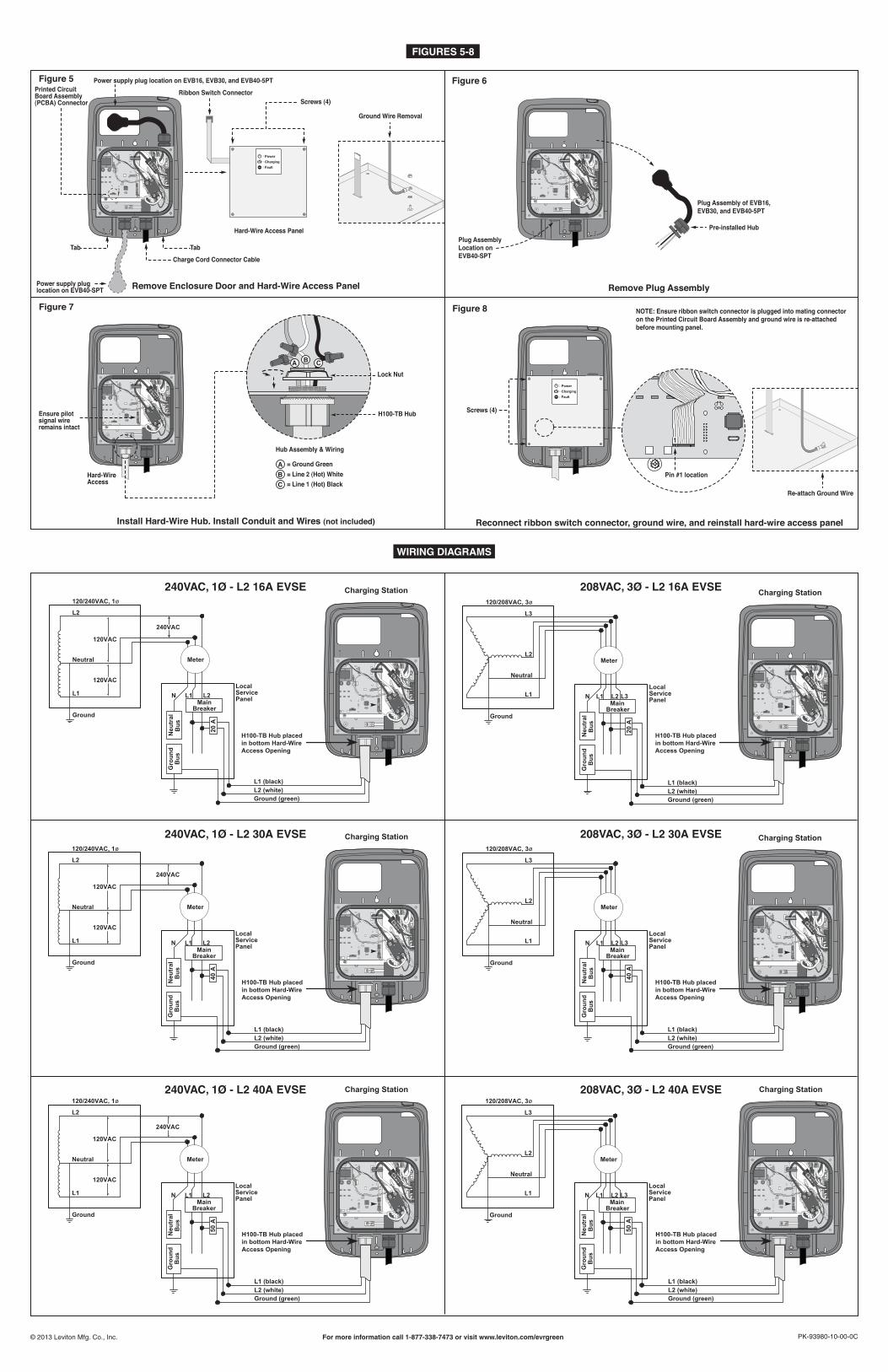
1. DepressreleasetabsonbottomofEnclosureandremoveEnclosureDoorbycarefullyliftingupandawayfromtheEnclosure (see Figure 2).Useapin-in-TorxType25screwdrivertoremovetheMetalHard-WireAccessPanel(with4screws). IMPORTANT NOTE:CarefullyremovetheribbonswitchconnectorfromprintedcircuitboardassemblyandthegroundwirefromtheHard-WireAccessPanelbeforesettingitaside(Figure 5).
2. TheHard-wireAccessopeningislocatedatthebottomoftheAccessPanelshowninFigure 7.LoosenwireconnectorsandretainforStep4.Removepre-installedhubanddisconnectPlugAssembly(see Figure 6).NOTE:IfthePlugAssemblyisremovedfromthetoplocation,blockthisopeningusingthePlugandGasketfromthebottomholetomaintainwatertightness(NEMA4)oftheChargingStation.
3. InstalltheH100-TBHub(Figure 7).Torquehubto65in-lbs.4. RundedicatedcircuitspertheNationalElectricCodeandlocalbuildingcodes.Thecircuitmusthaveanadditional15inchesofloosewirestoterminatetheconnectionsontheinsideof
theChargingStation.SecureconduittoH100-TBHubusingproperUL-listedconduitfitting.Theuseofareducermayberequiredbasedonconduitfittingselected.Stripwireends3/4inchandsecuretocorrespondingwiresfromtoroidassemblyandgroundwirefromterminalblockwithwireconnectorsasshowninFigure 7.NOTE:Useelectrically-conductivethreadsealantKOPR-SHIELD®CP8-TBorCP16byThomas&Betts®topreventwater/moisturepenetrationthroughthethreadingonfitting,reducernippleorthreadedconduit.Instructionforthreadsealantapplication:
a)Coat100%ofthemalethreadswiththeKOPR-SHIELD®compound.Workthecompounddownbetweenthethreads.b)Screwthreadedfitting/hub/reducer/conduittogetherandensurethatanoverflowofthreadsealantispresent.c)Thereisnocuretimeforthisproduct(theproductworksfromthepointofapplication).
NOTE:Useofductsealtoblockconduitopeningisneccessaryifconduitleadstoanon-NEMA4junctionbox(useofajunctionboxwithatleastaNEMA3Rratingisrequired).UseGardnerBenderDS-110ductseal(TheHomeDepot®).Instructionforductsealapplication(ifnecessary):
a)Ductsealapplicationneedstobedoneafterallwiringconnectionshavebeencompleted.b)Cleanhubsurfaceareasothatitisfreeofanydebrisorchemicalcontamination.c)Openthe1-poundductsealpackageandbreakoffa11/2"x11/2"ductsealcompoundpiece.d)Packtheductsealcompounddownwardintothehubopeninguntilthehubiscompletelysealed;ensurethatthecompoundencapsulatesthethreewirescompletely(seeFigure 4).e)Oncethematerialistightandsecure,levelthesurfaceflushwiththebottomofthehub.
5. Reconnectribbonswitchconnectorintomatingconnectoronprintedcircuitboardassemblyandreconnectgroundwire.ReinstalltheHard-WireAccessPanel(Figure 8) andcloseenclosuredoor.
6. Restorepoweratcircuitbreaker.Installation is complete. Refer to Level 2 - Electric Vehicle Charging Station User Guide for operation.
For Metal Stud Applications:• Wallanchorscapableofsupportingamaximumallowableloadof200lbs.For Solid Wall Applications:• Wallanchorscapableofsupportingamaximumallowableloadof200lbs.• Appropriateconduitandapplicablemountinghardware.
NOTE: Hard-Wire Access opening is located at the bottom of the Access Panel. Remove plug and gasket and place both on top where Plug Assembly and Pre-installed Hub were removed (Figure 7).
Gathertherequiredtoolsandpartsbeforestartinginstallation.Besuretofollowmanufacturer’sinstructionsforuseofanytoolsorpartsusedforthisinstallation.
AlternateHang Holes
Figure 3
• Drillwith3/16"bit • Studfinder• Measuringtape • Wirecutters/strippers• Pin-inTorxtype25driver • Pliers
•Level•Scratchawl•Keyholesaw•Utilityknife•#3Phillipsscrewdriver(formountingbracket)
Tools: Additional Parts (not included):
• Copperelectricalcable(seebelowforgauge) • #14woodmountingscrews(2)-studmount •CircuitBreaker-20A(EVB16)-40A(EVB30)or50A(EVB40)
•Conduit •Strainrelief(ifapplicable) •H100-TBHub(orengineeringequivalent)
Duct SealFigure 4
KOPR-SHIELD is a registered trademark of Jet-Lube, Inc
Thomas&Betts is a registered trademark of Thomas&Betts, Inc.
LIMITED 3 YEAR WARRANTY AND EXCLUSIONSLevitonwarrants to theoriginalconsumerpurchaserandnot for thebenefitofanyoneelse that thisproductat the timeof itssalebyLeviton is freeofdefects inmaterialsandworkmanshipundernormalandproperuse for threeyearsfromthepurchasedate.Leviton’sonlyobligationistocorrectsuchdefectsbyrepairorreplacement,atitsoption,ifwithinsuchthreeyearperiodtheproductisreturnedprepaid,withproofofpurchasedate,andadescriptionoftheproblemtoLeviton Mfg. Co., Inc. 201 North Service Road, Melville, N.Y. 11747.Thiswarrantyexcludesandthereisdisclaimedliabilityforlaborforremovalofthisproductorreinstallation.Thiswarrantyisvoidifthisproductis installed improperlyor inan improperenvironment,overloaded,misused,opened,abused,oraltered inanymanner,or isnotusedundernormaloperatingconditionsornot inaccordancewithany labelsor instructions.There are no other or implied warranties of any kind, including merchantability and fitness for a particular purpose,but ifany impliedwarranty is requiredby theapplicable jurisdiction, thedurationofanysuch impliedwarranty,including merchantability and fitness for a particular purpose, is limited to three years. Leviton is not liable for incidental, indirect, special, or consequential damages, including without limitation, damage to, or loss of use of, any equipment, lost sales or profits or delay or failure to perform this warranty obligation.Theremediesprovidedhereinare theexclusiveremediesunder thiswarranty,whetherbasedoncontract, tortorotherwise.
FOR CANADA ONLYForwarrantyinformationand/orproductreturns,residentsofCanadashouldcontactLevitoninwritingatLeviton Manufacturing of Canada Ltd to the attention of the Quality Assurance Department, 165 Hymus Blvd, Pointe-Claire (Quebec), Canada H9R 1E9orbytelephoneat1 800 405-5320.
PK-93980-10-00-0CFor more information call 1-877-338-7473 or visit www.leviton.com/evrgreen©2013LevitonMfg.Co.,Inc.
WIRING DIAGRAMS
FIGURES 5-8
L2
120VAC
Neu
tralGround
240VAC
Service
Ground (green)
ø
L1 PanelL1
Meter
L2
Neutral
N
120VAC
Breaker
Bus
Gro
und
Bus
Main
Local
L2 (white)
120/240VAC, 1
L1 (black)
20 A
H100-TB Hub placed in bottom Hard-Wire Access Opening
Charging Station
L3
Neutral
N
Ground
ø
Neu
tral
MeterL2
L1
L3
L1
Breaker
20 A
Bus
Gro
und
Bus
L2LocalServicePanel
120/208VAC, 3
Main
H100-TB Hub placed in bottom Hard-Wire Access Opening
Ground (green)L2 (white)L1 (black)
Main
Neutral
Ground
Service
ø
Meter
L2L1L1 N
L2
Breaker
240VAC
Gro
und
Bus
Neu
tral
Local
Bus
Panel
120VAC
120VAC
120/240VAC, 1
40 A
H100-TB Hub placed in bottom Hard-Wire Access Opening
Ground (green)L2 (white)L1 (black)
L1 L2
Ground
PanelBreaker
Local
Gro
und
Neu
tral
L1
L2
ø
Bus
L3
Meter
Bus
ServiceN
120/208VAC, 3
Main
40 A
Neutral
L3
H100-TB Hub placed in bottom Hard-Wire Access Opening
Ground (green)L2 (white)L1 (black)
50 A
120/240VAC, 1ø
L2
Neutral
120VAC
Meter
L1
Ground
MainN L1 L2
Bus
Gro
und
Breaker
Neu
tral
LocalServicePanel
Bus
120VAC
240VAC
H100-TB Hub placed in bottom Hard-Wire Access Opening
Ground (green)L2 (white)L1 (black)
L3
Neutral
Panel
Gro
und
N
ø
L3
Neu
tral
L2
L1 L1 L2
GroundBreaker
Meter
Bus
Local
Bus
Service
120/208VAC, 3
Main
50 A
H100-TB Hub placed in bottom Hard-Wire Access Opening
Ground (green)L2 (white)L1 (black)
240VAC, 1Ø - L2 16A EVSE 208VAC, 3Ø - L2 16A EVSE
240VAC, 1Ø - L2 30A EVSE 208VAC, 3Ø - L2 30A EVSE
240VAC, 1Ø - L2 40A EVSE 208VAC, 3Ø - L2 40A EVSE
Charging Station
Charging Station Charging Station
Charging StationCharging Station
Figure 5
Remove Enclosure Door and Hard-Wire Access Panel
Screws (4)
Tab
Hard-Wire Access Panel
Ribbon Switch Connector
Ground Wire Removal
Printed Circuit Board Assembly (PCBA) Connector
Tab
Charge Cord Connector Cable
Power supply plug location on EVB16, EVB30, and EVB40-5PT
Power supply plug location on EVB40-SPT
Figure 6
Remove Plug Assembly
Pre-installed Hub
Plug AssemblyLocation onEVB40-SPT
Plug Assembly of EVB16, EVB30, and EVB40-5PT
Figure 7
Install Hard-Wire Hub. Install Conduit and Wires (not included)
ABC = Line 1 (Hot) Black
= Line 2 (Hot) White= Ground Green
Lock Nut
Hub Assembly & Wiring
A CB
H100-TB HubEnsure pilot signal wire remains intact
Hard-WireAccess
Figure 8
Re-attach Ground Wire
Pin #1 location
Screws (4)
NOTE: Ensure ribbon switch connector is plugged into mating connectoron the Printed Circuit Board Assembly and ground wire is re-attached before mounting panel.
1
Reconnect ribbon switch connector, ground wire, and reinstall hard-wire access panel


