
COS 461: Computer Networks Spring 2008 (MW 1:30‐2:50 in COS 105)
Mike Freedman
hEp://www.cs.princeton.edu/courses/archive/spring09/cos461/
IP Packet Switching
Goals of Today’s Lecture • ConnecTvity
– Links and nodes – Circuit switching – Packet switching
• IP service model – Best‐effort packet delivery – IP as the Internet’s “narrow waist” – Design philosophy of IP
• IP packet structure – Fields in the IP header – Traceroute using TTL field – Source‐address spoofing
2
Simple Network: Nodes and a Link
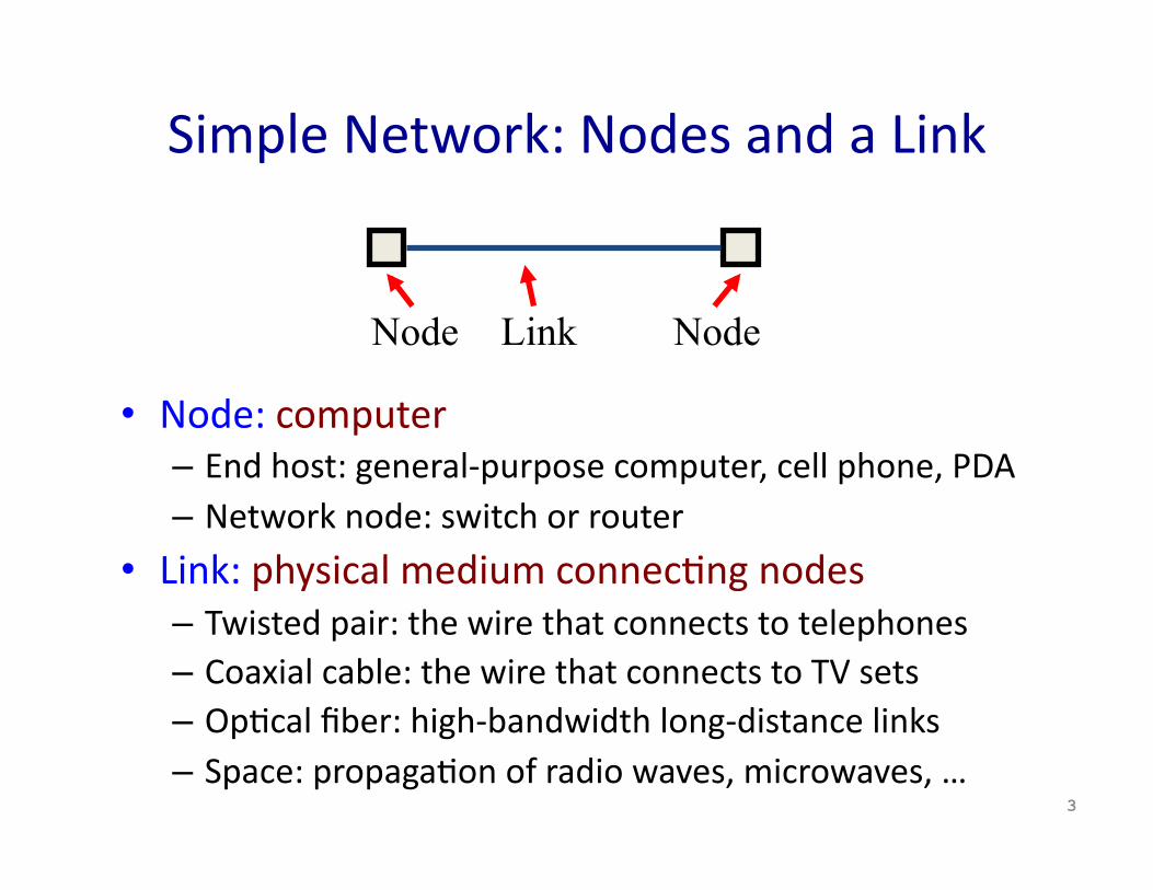
• Node: computer – End host: general‐purpose computer, cell phone, PDA – Network node: switch or router
• Link: physical medium connecTng nodes – Twisted pair: the wire that connects to telephones – Coaxial cable: the wire that connects to TV sets – OpTcal fiber: high‐bandwidth long‐distance links – Space: propagaTon of radio waves, microwaves, …
3
Node Link Node
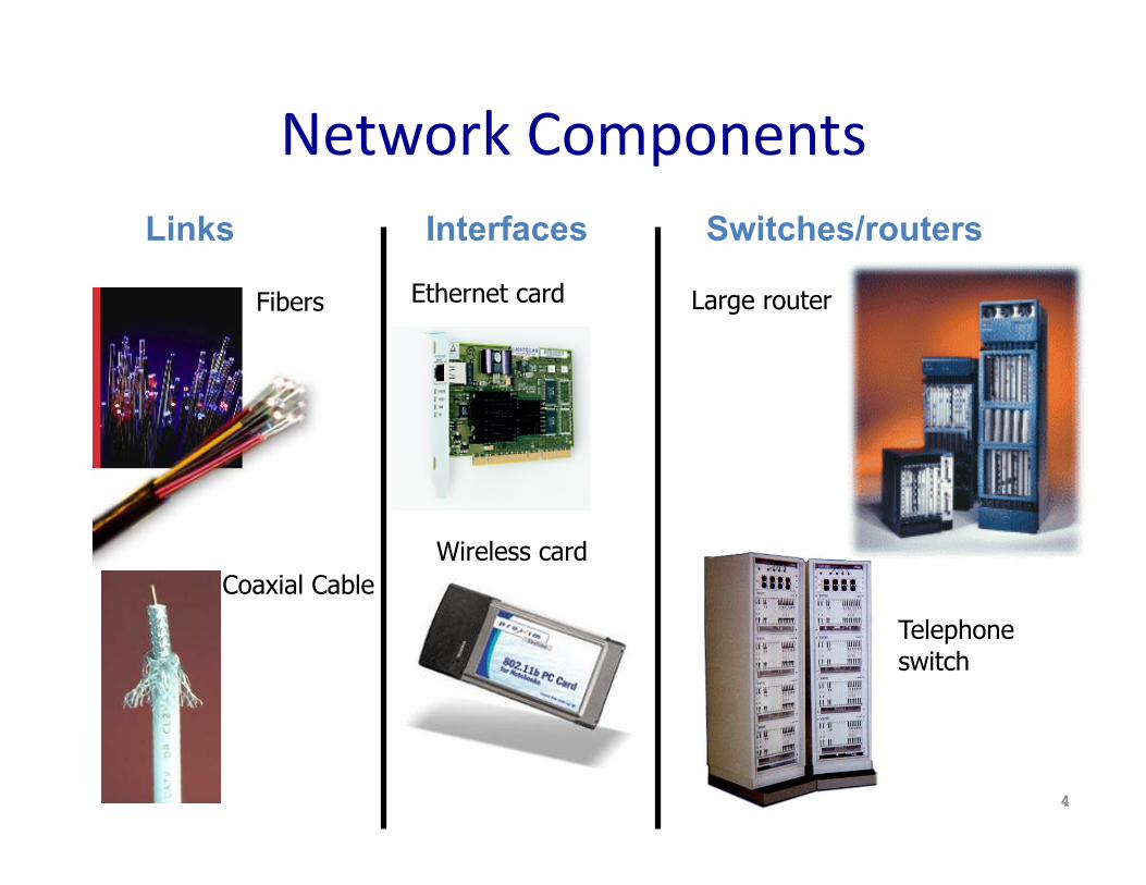
Network Components
4
Fibers
Coaxial Cable
Links Interfaces Switches/routers
Ethernet card
Wireless card
Large router
Telephone switch
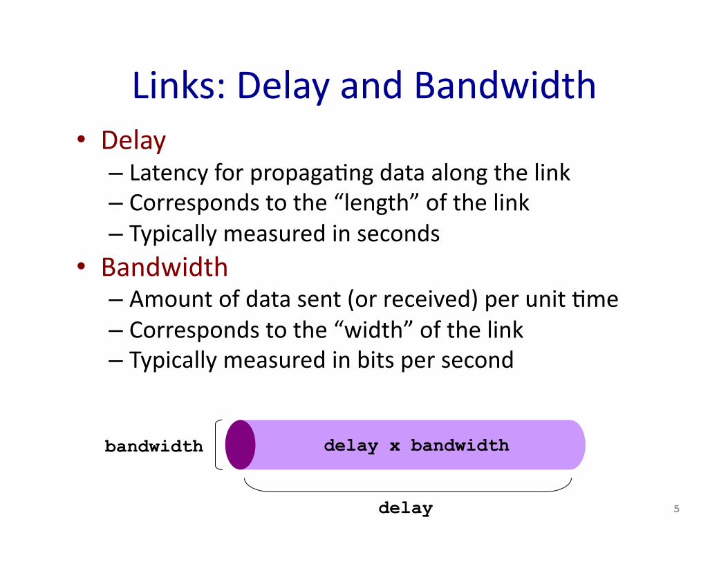
Links: Delay and Bandwidth • Delay
– Latency for propagaTng data along the link – Corresponds to the “length” of the link – Typically measured in seconds
• Bandwidth – Amount of data sent (or received) per unit Tme – Corresponds to the “width” of the link – Typically measured in bits per second
5
bandwidth
delay
delay x bandwidth

ConnecTng More Than Two Hosts • MulT‐access link: Ethernet, wireless
– Single physical link, shared by mulTple nodes – LimitaTons on distance and number of nodes
• Point‐to‐point links: fiber‐opTc cable – Only two nodes (separate link per pair of nodes) – LimitaTons on the number of adapters per node
6
multi-access link point-to-point links
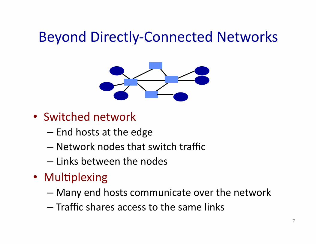
Beyond Directly‐Connected Networks
• Switched network – End hosts at the edge – Network nodes that switch traffic – Links between the nodes
• MulTplexing – Many end hosts communicate over the network – Traffic shares access to the same links
7

Circuit Switching (e.g., Phone Network)
• Source establishes connecTon to desTnaTon – Node along the path store connecTon info – Nodes may reserve resources for the connecTon
• Source sends data over the connecTon – No desTnaTon address, since nodes know path
• Source tears down connecTon when done
8
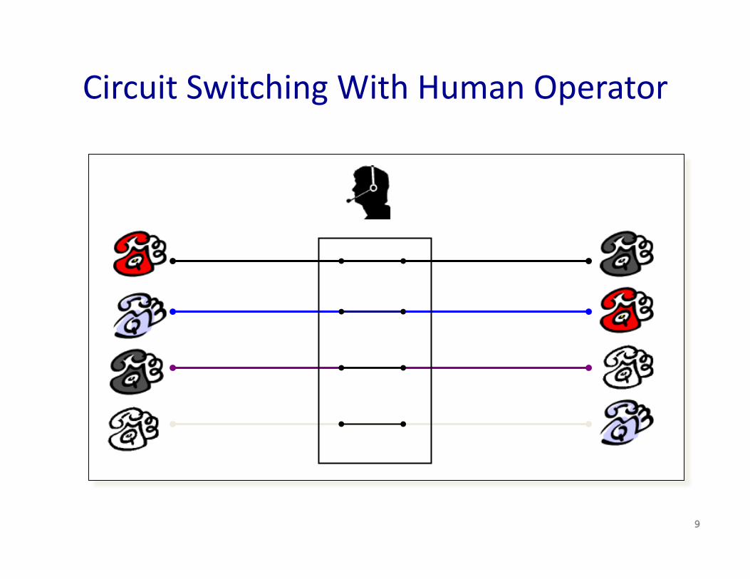
Circuit Switching With Human Operator
9

Circuit Switching: MulTplexing a Link
• Time‐division – Each circuit allocated certain Tme slots
• Frequency‐division – Each circuit allocated certain frequencies
10
time frequency
time
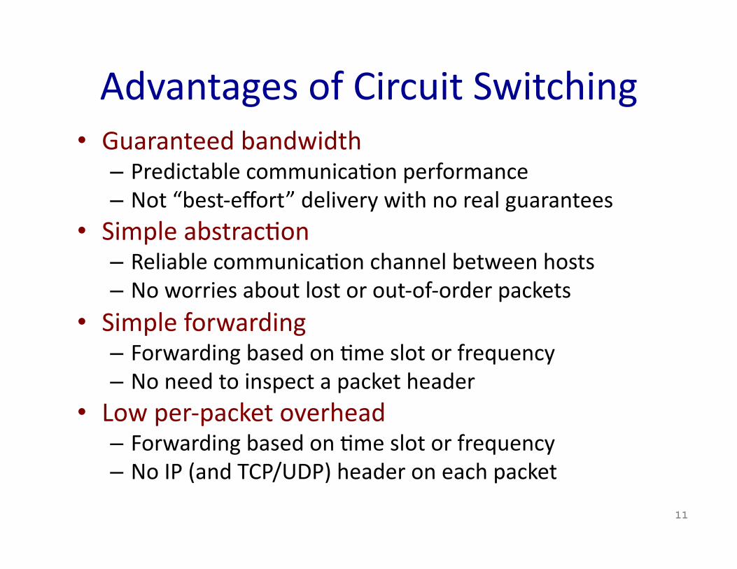
Advantages of Circuit Switching • Guaranteed bandwidth
– Predictable communicaTon performance – Not “best‐effort” delivery with no real guarantees
• Simple abstracTon – Reliable communicaTon channel between hosts – No worries about lost or out‐of‐order packets
• Simple forwarding – Forwarding based on Tme slot or frequency – No need to inspect a packet header
• Low per‐packet overhead – Forwarding based on Tme slot or frequency – No IP (and TCP/UDP) header on each packet
11
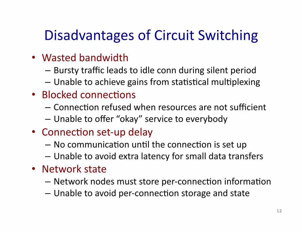
Disadvantages of Circuit Switching • Wasted bandwidth
– Bursty traffic leads to idle conn during silent period – Unable to achieve gains from staTsTcal mulTplexing
• Blocked connecTons – ConnecTon refused when resources are not sufficient – Unable to offer “okay” service to everybody
• ConnecTon set‐up delay – No communicaTon unTl the connecTon is set up – Unable to avoid extra latency for small data transfers
• Network state – Network nodes must store per‐connecTon informaTon – Unable to avoid per‐connecTon storage and state
12

Packet Switching (e.g., Internet) • Data traffic divided into packets
– Each packet contains a header (with address) • Packets travel separately through network
– Packet forwarding based on the header – Network nodes may store packets temporarily
• DesTnaTon reconstructs the message
13

Packet Switching: StaTsTcal MulTplexing
14
Packets
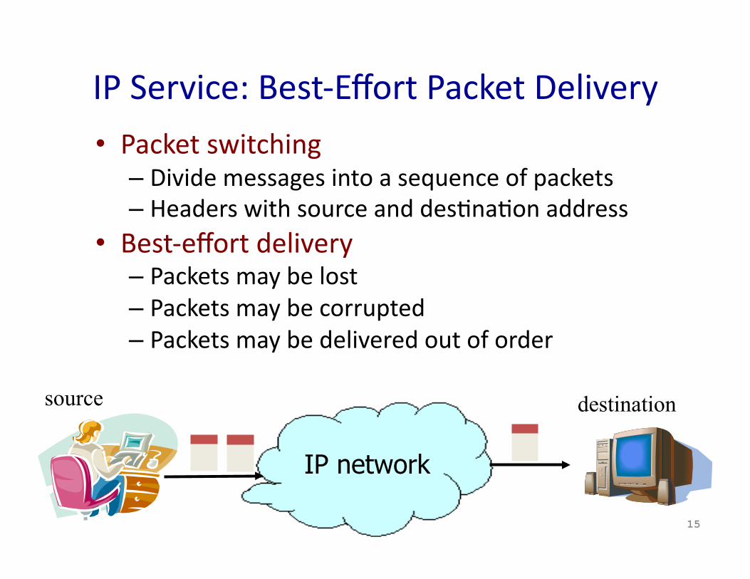
IP Service: Best‐Effort Packet Delivery
15
• Packet switching – Divide messages into a sequence of packets – Headers with source and desTnaTon address
• Best‐effort delivery – Packets may be lost – Packets may be corrupted – Packets may be delivered out of order
source destination
IP network
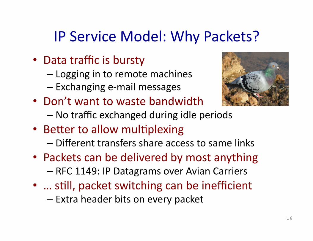
IP Service Model: Why Packets? • Data traffic is bursty
– Logging in to remote machines – Exchanging e‐mail messages
• Don’t want to waste bandwidth – No traffic exchanged during idle periods
• BeEer to allow mulTplexing – Different transfers share access to same links
• Packets can be delivered by most anything – RFC 1149: IP Datagrams over Avian Carriers
• … sTll, packet switching can be inefficient – Extra header bits on every packet
16
IP Service Model: Why Best‐Effort? • IP means never having to say you’re sorry…
– Don’t need to reserve bandwidth and memory
– Don’t need to do error detecTon & correcTon – Don’t need to remember from one packet to next
• Easier to survive failures – Transient disrupTons are okay during failover
• … but, applicaTons do want efficient, accurate transfer of data in order, in a Tmely fashion
17

IP Service: Best‐Effort is Enough • No error detecTon or correcTon
– Higher‐level protocol can provide error checking • Successive packets may not follow the same path
– Not a problem as long as packets reach the desTnaTon
• Packets can be delivered out‐of‐order – Receiver can put packets back in order (if necessary)
• Packets may be lost or arbitrarily delayed – Sender can send the packets again (if desired)
• No network congesTon control (beyond “drop”) – Sender can slow down in response to loss or delay
18
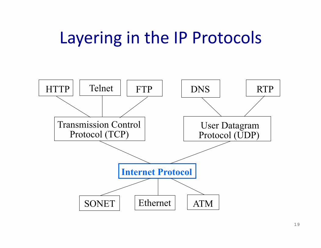
Layering in the IP Protocols
19
Internet Protocol
Transmission Control Protocol (TCP)
User Datagram Protocol (UDP)
Telnet HTTP
SONET ATM Ethernet
RTP DNS FTP

History: Why IP Packets? • IP proposed in the early 1970s
– Defense Advanced Research Project Agency (DARPA) • Goal: connect exisTng networks
– To develop an effecTve technique for mulTplexed uTlizaTon of exisTng interconnected networks
– E.g., connect packet radio networks to the ARPAnet • MoTvaTng applicaTons
– Remote login to server machines – Inherently bursty traffic with long silent periods
• Prior ARPAnet experience with packet switching – Previous DARPA project – Demonstrated store‐and‐forward packet switching
20
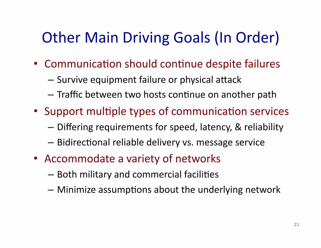
Other Main Driving Goals (In Order)
• CommunicaTon should conTnue despite failures – Survive equipment failure or physical aEack – Traffic between two hosts conTnue on another path
• Support mulTple types of communicaTon services – Differing requirements for speed, latency, & reliability
– BidirecTonal reliable delivery vs. message service
• Accommodate a variety of networks – Both military and commercial faciliTes
– Minimize assumpTons about the underlying network
21
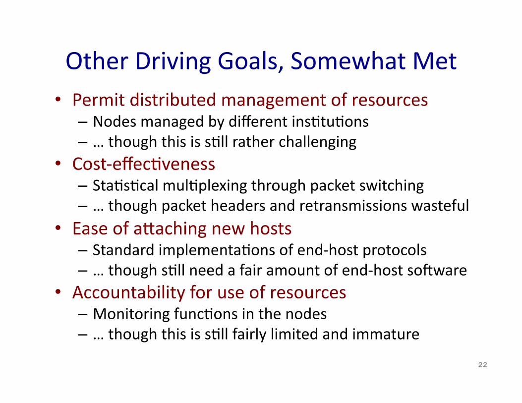
Other Driving Goals, Somewhat Met • Permit distributed management of resources
– Nodes managed by different insTtuTons – … though this is sTll rather challenging
• Cost‐effecTveness – StaTsTcal mulTplexing through packet switching – … though packet headers and retransmissions wasteful
• Ease of aEaching new hosts – Standard implementaTons of end‐host protocols – … though sTll need a fair amount of end‐host solware
• Accountability for use of resources – Monitoring funcTons in the nodes – … though this is sTll fairly limited and immature
22
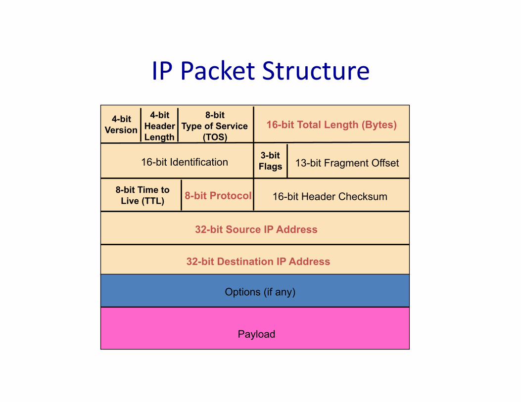
IP Packet Structure
4-bit Version
4-bit Header Length
8-bit Type of Service
(TOS) 16-bit Total Length (Bytes)
16-bit Identification 3-bit Flags 13-bit Fragment Offset
8-bit Time to Live (TTL) 8-bit Protocol 16-bit Header Checksum
32-bit Source IP Address
32-bit Destination IP Address
Options (if any)
Payload
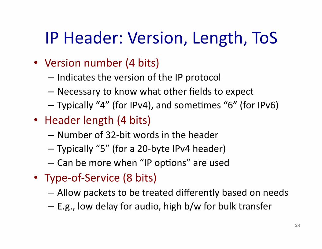
IP Header: Version, Length, ToS • Version number (4 bits)
– Indicates the version of the IP protocol – Necessary to know what other fields to expect – Typically “4” (for IPv4), and someTmes “6” (for IPv6)
• Header length (4 bits) – Number of 32‐bit words in the header – Typically “5” (for a 20‐byte IPv4 header) – Can be more when “IP opTons” are used
• Type‐of‐Service (8 bits) – Allow packets to be treated differently based on needs – E.g., low delay for audio, high b/w for bulk transfer
24
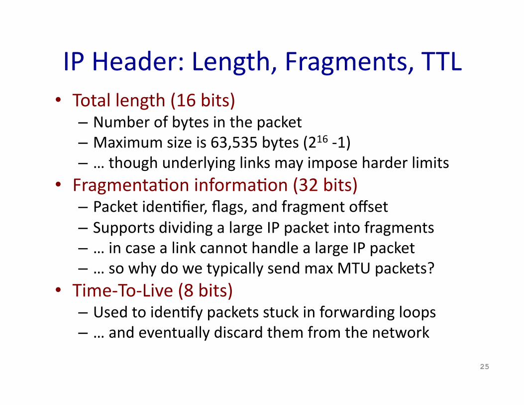
IP Header: Length, Fragments, TTL • Total length (16 bits)
– Number of bytes in the packet – Maximum size is 63,535 bytes (216 ‐1) – … though underlying links may impose harder limits
• FragmentaTon informaTon (32 bits) – Packet idenTfier, flags, and fragment offset – Supports dividing a large IP packet into fragments – … in case a link cannot handle a large IP packet – … so why do we typically send max MTU packets?
• Time‐To‐Live (8 bits) – Used to idenTfy packets stuck in forwarding loops – … and eventually discard them from the network
25
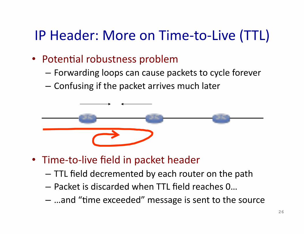
IP Header: More on Time‐to‐Live (TTL)
• PotenTal robustness problem – Forwarding loops can cause packets to cycle forever – Confusing if the packet arrives much later
• Time‐to‐live field in packet header – TTL field decremented by each router on the path – Packet is discarded when TTL field reaches 0… – …and “Tme exceeded” message is sent to the source
26
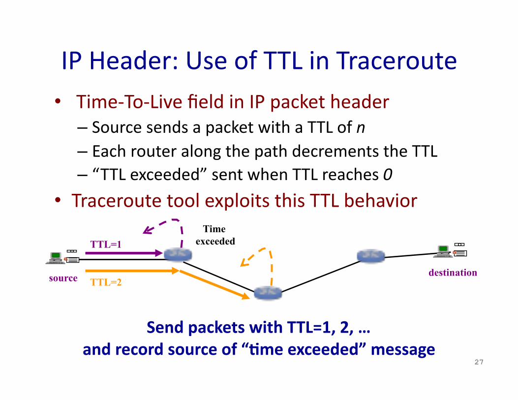
IP Header: Use of TTL in Traceroute • Time‐To‐Live field in IP packet header
– Source sends a packet with a TTL of n – Each router along the path decrements the TTL – “TTL exceeded” sent when TTL reaches 0
• Traceroute tool exploits this TTL behavior
27
source destination
TTL=1 Time
exceeded
TTL=2
Send packets with TTL=1, 2, … and record source of “;me exceeded” message
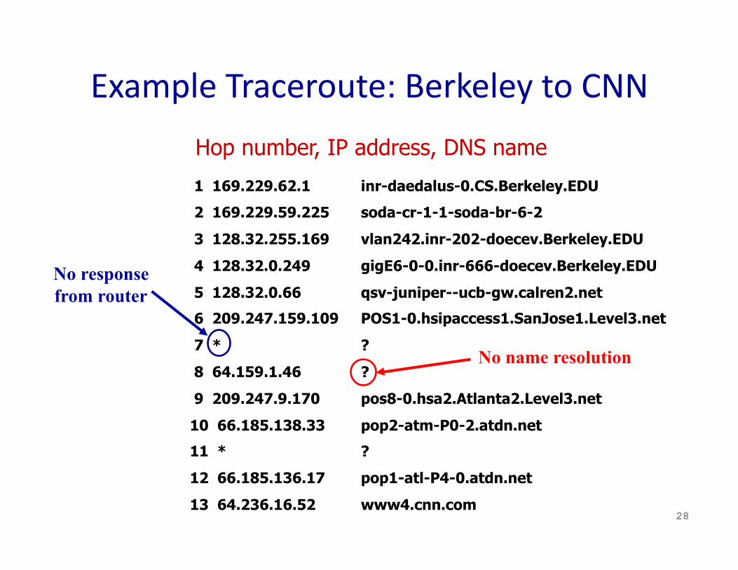
Example Traceroute: Berkeley to CNN
28
1 169.229.62.1
2 169.229.59.225
3 128.32.255.169
4 128.32.0.249
5 128.32.0.66
6 209.247.159.109
7 *
8 64.159.1.46
9 209.247.9.170
10 66.185.138.33
11 *
12 66.185.136.17
13 64.236.16.52
Hop number, IP address, DNS name
inr-daedalus-0.CS.Berkeley.EDU
soda-cr-1-1-soda-br-6-2
vlan242.inr-202-doecev.Berkeley.EDU
gigE6-0-0.inr-666-doecev.Berkeley.EDU
qsv-juniper--ucb-gw.calren2.net
POS1-0.hsipaccess1.SanJose1.Level3.net
?
?
pos8-0.hsa2.Atlanta2.Level3.net
pop2-atm-P0-2.atdn.net
?
pop1-atl-P4-0.atdn.net
www4.cnn.com
No response from router
No name resolution
Try Running Traceroute Yourself • On UNIX machine
– Traceroute – E.g., “traceroute cnn.com” or “traceroute 12.1.1.1”
• On Windows machine – Tracert – E.g., “tracert cnn.com” or “tracert 12.1.1.1”
• Common uses of traceroute – Discover the topology of the Internet – Debug performance and reachability problems
29

IP Header Fields: Transport Protocol • Protocol (8 bits)
– IdenTfies the higher‐level protocol • E.g., “6” for the Transmission Control Protocol (TCP) • E.g., “17” for the User Datagram Protocol (UDP)
– Important for demulTplexing at receiving host • Indicates what kind of header to expect next
30
IP header IP header
TCP header UDP header
protocol=6 protocol=17
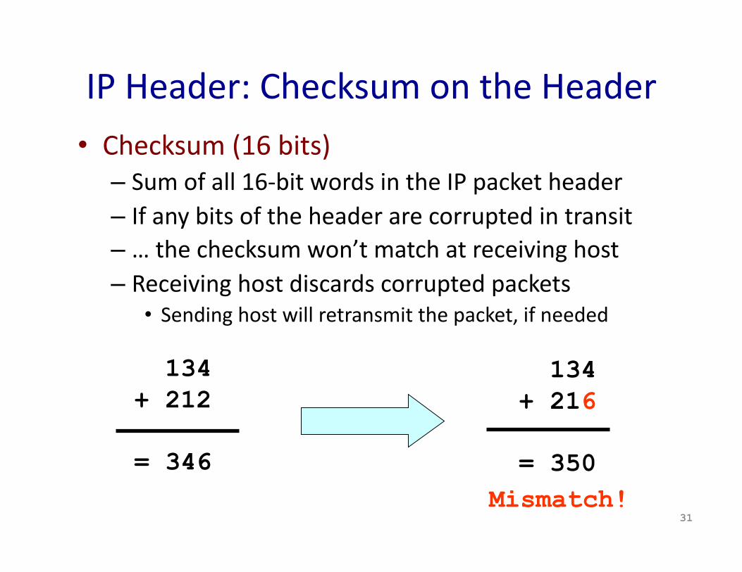
IP Header: Checksum on the Header
• Checksum (16 bits) – Sum of all 16‐bit words in the IP packet header – If any bits of the header are corrupted in transit – … the checksum won’t match at receiving host – Receiving host discards corrupted packets
• Sending host will retransmit the packet, if needed
31
134 + 212
= 346
134 + 216
= 350 Mismatch!
IP Header: To and From Addresses • Two IP addresses
– Source IP address (32 bits) – DesTnaTon IP address (32 bits)
• DesTnaTon address – Unique idenTfier for the receiving host – Allows each node to make forwarding decisions
• Source address – Unique idenTfier for the sending host – Recipient can decide whether to accept packet – Enables recipient to send a reply back to source
32
Source Address: What if Source Lies? • Source address should be the sending host
– But, who’s checking, anyway? – You could send packets with any source you want
• Why would someone want to do this? – Launch a denial‐of‐service aEack
• Send excessive packets to the desTnaTon • … to overload the node, or the links leading to the node
– Evade detecTon by “spoofing” • But, the vicTm could idenTfy you by the source address • So, you can put someone else’s source address in the packets
– Also, an aEack against the spoofed host • Spoofed host is wrongly blamed • Spoofed host may receive return traffic from the receiver
33
Summary: Packet Switching Review
• Efficient – Can send from any input that is ready
• General – MulTple types of applicaTons
• Accommodates bursty traffic – AddiTon of queues
• Store and forward – Packets are self contained units – Can use alternate paths – reordering
• ContenTon (i.e., no isolaTon) – CongesTon – Delay
34
Next Lecture • IP routers
– Packet forwarding – Components of a router
• Reading for this week – Chapter 3: SecTons 3.1 and 3.4 – Chapter 4: SecTons 4.1.1 ‐‐ 4.1.4
• Please subscribe to the course mailing list – hEps://lists.cs.princeton.edu/mailman/lisTnfo/cos461
35


