IEEE 802.3 50 Gb/s, 100 Gb/s, and 200 Gb/s Ethernet Task Force1
Vittal Balasubramanian, Dell
Yasuo Hidaka, Fujitsu
Upen Reddy Kareti, Cisco
Erdem Matoglu, Amphenol-TCS
Jim Nadolny, Samtec
Rick Rabinovich, IXIA
Adee Ran, Intel
Edward P. Sayre, Ph. D., P. E., Teraspeed Consulting – a Division of Samtec
Jeremy Stephens, Intel
Andrew Zambell, FCI
2 IEEE 802.3 50 Gb/s, 100 Gb/s, and 200 Gb/s Ethernet Task Force
Presentation Purpose
Propose an informative baseline annex based on feedback from: http://www.ieee802.org/3/cd/public/adhoc/archive/Mellitz_062216_3cd_01_adhoc.pdf
3 IEEE 802.3 50 Gb/s, 100 Gb/s, and 200 Gb/s Ethernet Task Force
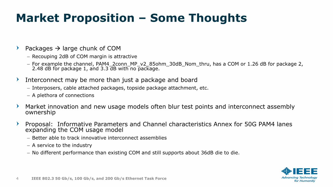
Market Proposition – Some Thoughts
Packages large chunk of COM
– Recouping 2dB of COM margin is attractive
– For example the channel, PAM4_2conn_MP_v2_85ohm_30dB_Nom_thru, has a COM or 1.26 dB for package 2, 2.48 dB for package 1, and 3.3 dB with no package.
Interconnect may be more than just a package and board
– Interposers, cable attached packages, topside package attachment, etc.
– A plethora of connections
Market innovation and new usage models often blur test points and interconnect assembly ownership
Proposal: Informative Parameters and Channel characteristics Annex for 50G PAM4 lanes expanding the COM usage model
– Better able to track innovative interconnect assemblies
– A service to the industry
– No different performance than existing COM and still supports about 36dB die to die.
4 IEEE 802.3 50 Gb/s, 100 Gb/s, and 200 Gb/s Ethernet Task Force
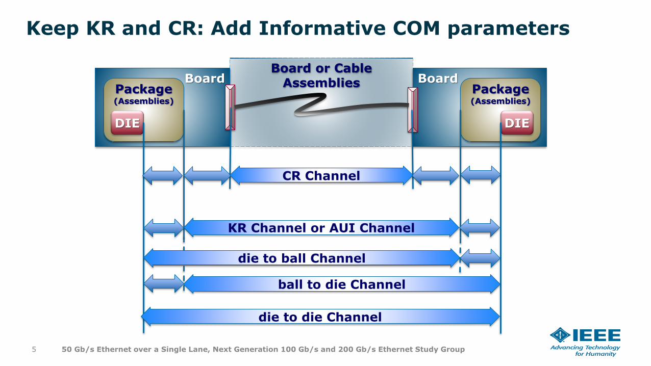
Board or Cable Assemblies
Keep KR and CR: Add Informative COM parameters
5 50 Gb/s Ethernet over a Single Lane, Next Generation 100 Gb/s and 200 Gb/s Ethernet Study Group
BoardPackage (Assemblies)
DIE
BoardPackage (Assemblies)
DIE
CR Channel
KR Channel or AUI Channel
die to ball Channel
die to die Channel
ball to die Channel
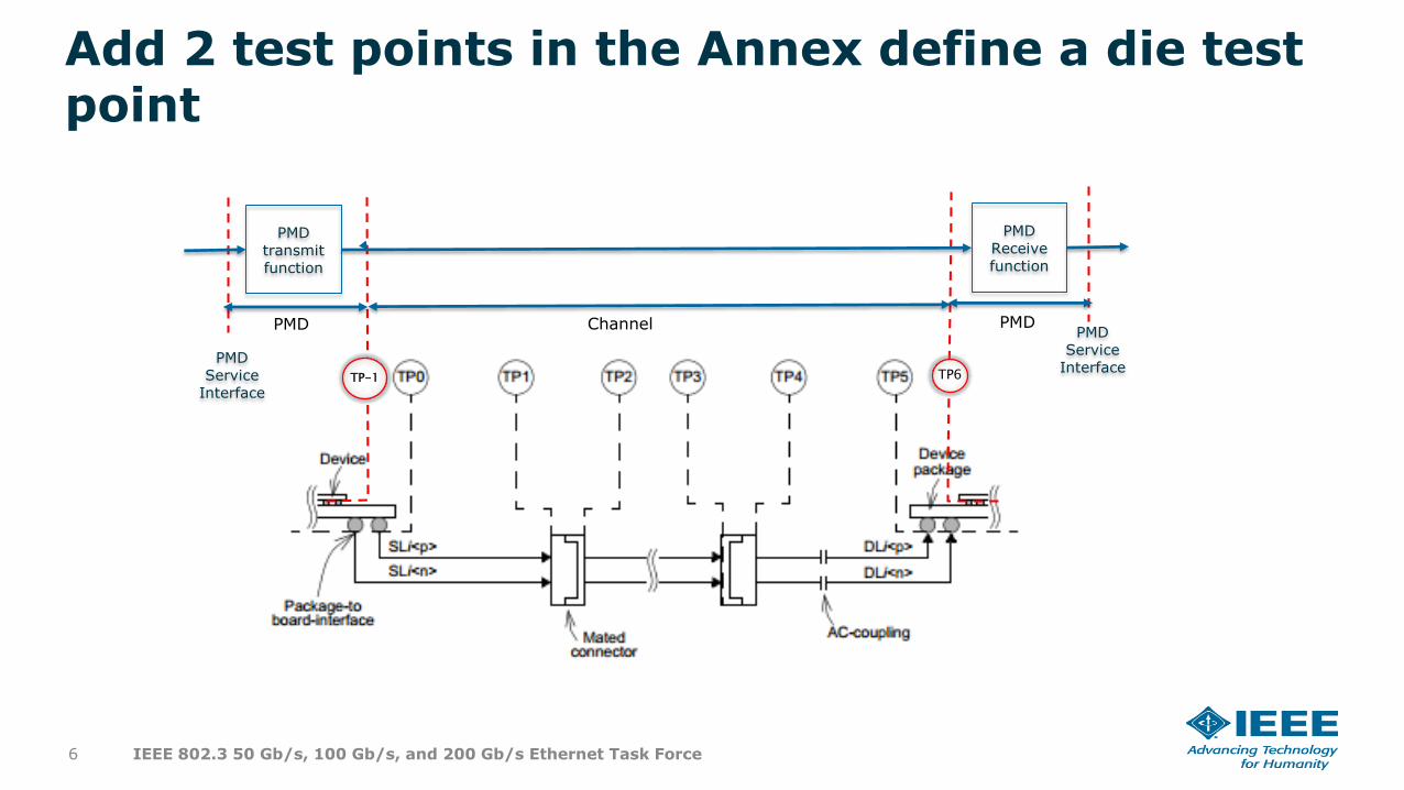
Add 2 test points in the Annex define a die test point
6 IEEE 802.3 50 Gb/s, 100 Gb/s, and 200 Gb/s Ethernet Task Force
TP-1 TP6
PMDtransmit function
PMDReceive function
PMD Service
InterfacePMD
Service Interface
Channel PMDPMD
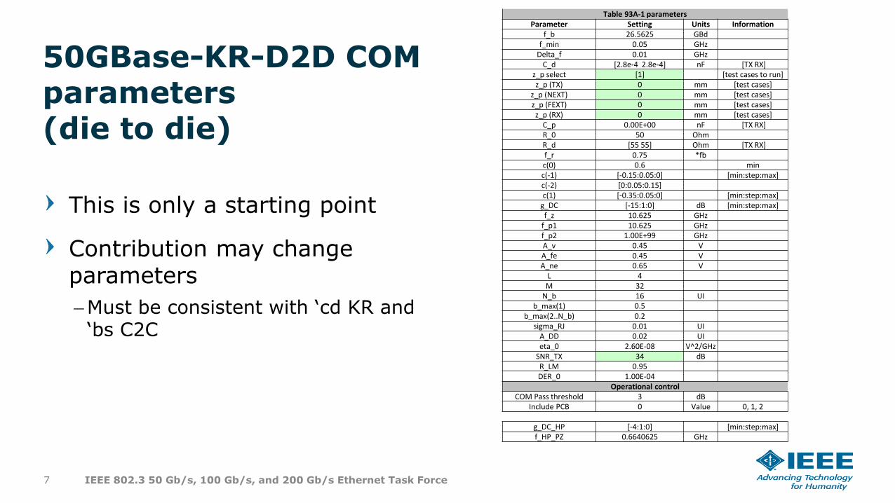
This is only a starting point
Contribution may change parameters
–Must be consistent with ‘cd KR and ‘bs C2C
Table 93A-1 parametersParameter Setting Units Information
f_b 26.5625 GBdf_min 0.05 GHz
Delta_f 0.01 GHzC_d [2.8e-4 2.8e-4] nF [TX RX]
z_p select [1] [test cases to run]z_p (TX) 0 mm [test cases]
z_p (NEXT) 0 mm [test cases]z_p (FEXT) 0 mm [test cases]z_p (RX) 0 mm [test cases]
C_p 0.00E+00 nF [TX RX]R_0 50 OhmR_d [55 55] Ohm [TX RX]f_r 0.75 *fbc(0) 0.6 minc(-1) [-0.15:0.05:0] [min:step:max]c(-2) [0:0.05:0.15]c(1) [-0.35:0.05:0] [min:step:max]
g_DC [-15:1:0] dB [min:step:max]f_z 10.625 GHz
f_p1 10.625 GHzf_p2 1.00E+99 GHzA_v 0.45 VA_fe 0.45 VA_ne 0.65 V
L 4M 32
N_b 16 UIb_max(1) 0.5
b_max(2..N_b) 0.2sigma_RJ 0.01 UI
A_DD 0.02 UIeta_0 2.60E-08 V^2/GHz
SNR_TX 34 dBR_LM 0.95DER_0 1.00E-04
Operational controlCOM Pass threshold 3 dB
Include PCB 0 Value 0, 1, 2
g_DC_HP [-4:1:0] [min:step:max]f_HP_PZ 0.6640625 GHz
50GBase-KR-D2D COM parameters(die to die)
7 IEEE 802.3 50 Gb/s, 100 Gb/s, and 200 Gb/s Ethernet Task Force
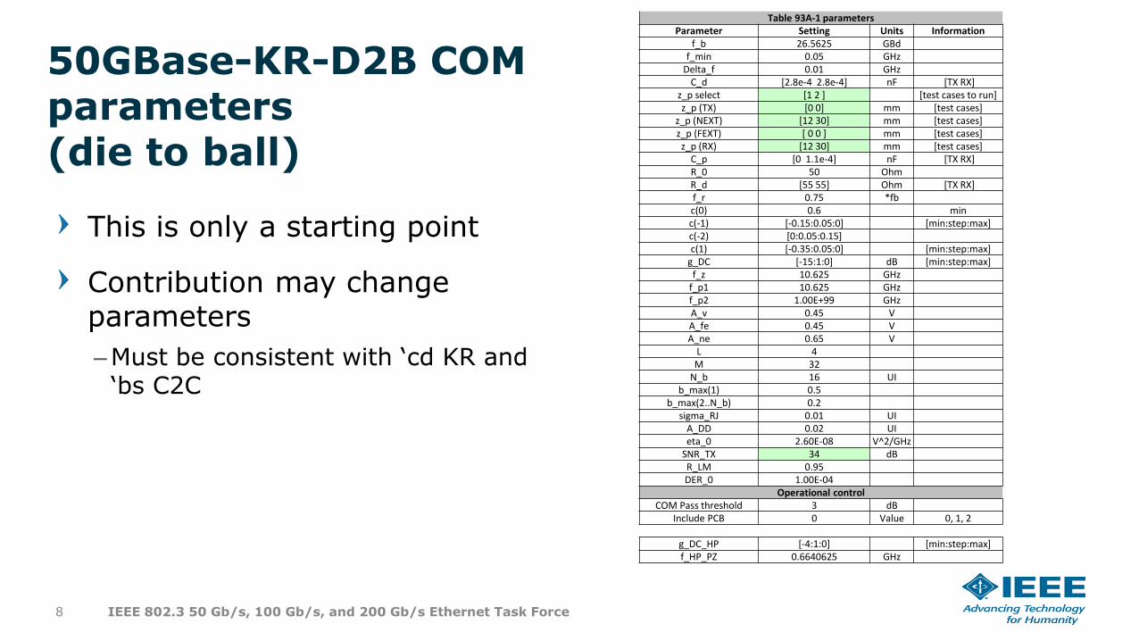
This is only a starting point
Contribution may change parameters
–Must be consistent with ‘cd KR and ‘bs C2C
Table 93A-1 parametersParameter Setting Units Information
f_b 26.5625 GBdf_min 0.05 GHz
Delta_f 0.01 GHzC_d [2.8e-4 2.8e-4] nF [TX RX]
z_p select [1 2 ] [test cases to run]z_p (TX) [0 0] mm [test cases]
z_p (NEXT) [12 30] mm [test cases]z_p (FEXT) [ 0 0 ] mm [test cases]z_p (RX) [12 30] mm [test cases]
C_p [0 1.1e-4] nF [TX RX]R_0 50 OhmR_d [55 55] Ohm [TX RX]f_r 0.75 *fbc(0) 0.6 minc(-1) [-0.15:0.05:0] [min:step:max]c(-2) [0:0.05:0.15]c(1) [-0.35:0.05:0] [min:step:max]
g_DC [-15:1:0] dB [min:step:max]f_z 10.625 GHz
f_p1 10.625 GHzf_p2 1.00E+99 GHzA_v 0.45 VA_fe 0.45 VA_ne 0.65 V
L 4M 32
N_b 16 UIb_max(1) 0.5
b_max(2..N_b) 0.2sigma_RJ 0.01 UI
A_DD 0.02 UIeta_0 2.60E-08 V^2/GHz
SNR_TX 34 dBR_LM 0.95DER_0 1.00E-04
Operational controlCOM Pass threshold 3 dB
Include PCB 0 Value 0, 1, 2
g_DC_HP [-4:1:0] [min:step:max]f_HP_PZ 0.6640625 GHz
50GBase-KR-D2B COM parameters(die to ball)
8 IEEE 802.3 50 Gb/s, 100 Gb/s, and 200 Gb/s Ethernet Task Force
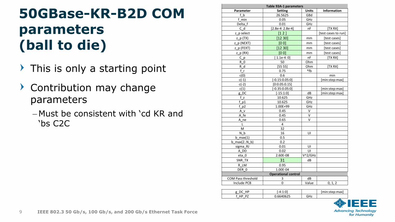
This is only a starting point
Contribution may change parameters
–Must be consistent with ‘cd KR and ‘bs C2C
Table 93A-1 parametersParameter Setting Units Information
f_b 26.5625 GBdf_min 0.05 GHz
Delta_f 0.01 GHzC_d [2.8e-4 2.8e-4] nF [TX RX]
z_p select [1 2 ] [test cases to run]
z_p (TX) [12 30] mm [test cases]
z_p (NEXT) [0 0] mm [test cases]
z_p (FEXT) [12 30] mm [test cases]
z_p (RX) [0 0] mm [test cases]
C_p [ 1.1e-4 0] nF [TX RX]R_0 50 OhmR_d [55 55] Ohm [TX RX]f_r 0.75 *fbc(0) 0.6 minc(-1) [-0.15:0.05:0] [min:step:max]c(-2) [0:0.05:0.15]c(1) [-0.35:0.05:0] [min:step:max]
g_DC [-15:1:0] dB [min:step:max]f_z 10.625 GHz
f_p1 10.625 GHzf_p2 1.00E+99 GHzA_v 0.45 VA_fe 0.45 VA_ne 0.65 V
L 4M 32
N_b 16 UIb_max(1) 0.5
b_max(2..N_b) 0.2sigma_RJ 0.01 UI
A_DD 0.02 UIeta_0 2.60E-08 V^2/GHz
SNR_TX 31 dB
R_LM 0.95DER_0 1.00E-04
Operational controlCOM Pass threshold 3 dB
Include PCB 0 Value 0, 1, 2
g_DC_HP [-4:1:0] [min:step:max]f_HP_PZ 0.6640625 GHz
50GBase-KR-B2D COM parameters(ball to die)
9 IEEE 802.3 50 Gb/s, 100 Gb/s, and 200 Gb/s Ethernet Task Force
Other parameters and considerations
50GAUI-D2D COM parameters
50GAUI-D2B COM parameters
50GAUI-B2D COM parameters
100G and 200G parameters are the same as 50G
10 50 Gb/s Ethernet over a Single Lane, Next Generation 100 Gb/s and 200 Gb/s Ethernet Study Group
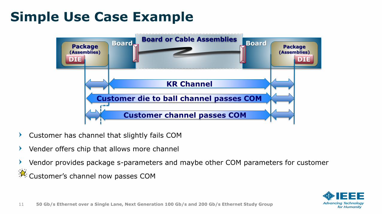
Simple Use Case Example
Customer has channel that slightly fails COM
Vender offers chip that allows more channel
Vendor provides package s-parameters and maybe other COM parameters for customer
Customer’s channel now passes COM
11 50 Gb/s Ethernet over a Single Lane, Next Generation 100 Gb/s and 200 Gb/s Ethernet Study Group
Board or Cable AssembliesBoard
Package (Assemblies)
DIE
BoardPackage
(Assemblies)
DIE
KR Channel
Customer die to ball channel passes COM
Customer channel passes COM
Proposal
Motion:
–Accept this proposal as a baseline for an informative Annex.
12 50 Gb/s Ethernet over a Single Lane, Next Generation 100 Gb/s and 200 Gb/s Ethernet Study Group


