
HARTZELL PROPELLER INC.
SERVICE LETTERTransmittal Sheet
HC-SL-61-277
Governor - Installation of Hartzell Propeller Inc. Governors
February 01, 2017
This page transmits a revision to Service Letter HC-SL-61-277.
• Original Issue, dated Nov 05/08 • Revision 1, dated Aug 06/09 • Revision 2, dated Oct 01/15 • Revision 3, dated Jan 08/16 • Revision 4, dated Oct 03/16 • Revision 5, dated Feb 01/17
Changes are shown by a change bar in the left margin of the revised pages.
Revision 5 is issued to change the following in the Service Letter:
- Revised the torque value for the B-3808-5 lock nut used on fixed RPM governors.
This Service Letter is reissued in its entirety.

HARTZELL PROPELLER INC.
SERVICE LETTERTransmittal Sheet
HC-SL-61-277
(This page is intentionally blank.)

HARTZELL PROPELLER INC.
SERVICE LETTERHC-SL-61-277
Governor - Installation of Hartzell Propeller Inc. Governors
HC-SL-61-277Page 1 of 16
Nov 05/08Revision 5, dated Feb 01/17
1. Planning Information
A. Effectivity
(1) All Hartzell Propeller Inc. governors are affected by this Service Letter.
WARNING: DO NOT USE OBSOLETE OR OUTDATED INFORMATION. PERFORM ALL INSPECTIONS OR WORK IN ACCORDANCE WITH THE MOST RECENT REVISION OF THIS SERVICE LETTER. INFORMATION CONTAINED IN THIS SERVICE LETTER MAY BE SIGNIFICANTLY CHANGED FROM EARLIER REVISIONS. FAILURE TO COMPLY WITH THIS SERVICE LETTER OR THE USE OF OBSOLETE INFORMATION MAY CREATE AN UNSAFE CONDITION THAT MAY RESULT IN DEATH, SERIOUS BODILY INJURY, AND/OR SUBSTANTIAL PROPERTY DAMAGE. REFER TO THE SERVICE LETTER INDEX FOR THE MOST RECENT REVISION LEVEL OF THIS SERVICE LETTER.
B. Concurrent Requirements
(1) Additional service documents may apply to the components/propellers affected by this Service Letter. Compliance with additional service documents may be necessary in conjunction with the completion of the Accomplishment Instructions in this Service Letter. Refer to the Hartzell Propeller Inc. website at www.hartzellprop.com for a cross-reference of service documents.
C. Reason
(1) This Service Letter provides installation information for governors manufactured by Hartzell Propeller Inc.
D. Description
(1) This Service Letter provides Additional Maintenance Information (AMI).
(2) This Service Letter provides general installation instructions for Hartzell Propeller Inc. governors if airframe manuals or other installation information is not available.
(3) These instructions may be used in conjunction with installation information supplied by the airframe manufacturer, or used as general installation guidelines when governor installation information is not provided by the airframe manufacturer.
(4) Information provided by the airframe or engine manufacturer supersedes information provided in this Service Letter.
© 2008, 2009, 2015, 2016, 2017 - Hartzell Propeller Inc. - All rights reserved
HARTZELL PROPELLER INC.
SERVICE LETTERHC-SL-61-277
Governor - Installation of Hartzell Propeller Inc. Governors
Nov 05/08Revision 5, dated Feb 01/17
HC-SL-61-277Page 2 of 16
E. Compliance(1) Compliance with this Service Letter is optional.
F. Approval(1) This technical document is approved by Hartzell Propeller Inc.
G. Manpower(1) Manpower will be variable, depending upon the location of the governor pad on
the engine, cowling removal, linkage connections, etc.H. Weight and Balance
(1) Governor weight will vary depending upon design. If necessary, weigh the governor before installation.
CAUTION: DO NOT USE OBSOLETE OR OUTDATED INFORMATION. PERFORM ALL INSPECTIONS OR WORK IN ACCORDANCE WITH THE MOST RECENT REVISION OF A DOCUMENT.
I. References(1) Pilot's Operating Handbook (POH).(2) Hartzell Propeller Inc. Standard Practices Manual 202A (61-01-02) -
(Volume 7, Consumable Materials and Packaging and Storage is available on the Hartzell Propeller Inc. website at www.hartzellprop.com)
2. Material InformationA. Material Necessary for Each Propeller/Component
Part Number Description Used onB-1104-1 Gasket, Governor Hartzell Propeller Inc. A-1 series
governors onlyB-1104 Gasket, Governor All other Hartzell Propeller Inc.
governors

HARTZELL PROPELLER INC.
SERVICE LETTERHC-SL-61-277
Governor - Installation of Hartzell Propeller Inc. Governors
HC-SL-61-277Page 3 of 16
Nov 05/08Revision 5, dated Feb 01/17
B. Consumable MaterialsCM Number Description QtyCM23 Stoddard Solvent ARCM11 Acetone or Denatured Alcohol ARCM116 Threadlocker, Removable ARCM288 Methyl Ethyl Ketone (MEK) ARCM219 Methyl Propyl Ketone (MPK) AR - Dow Corning® 7 Release Compound AR
NOTE: All CM numbers or materials in this Service Letter refer to the Consumable Materials chapter of Hartzell Propeller Inc. Standard Practices Manual 202A (61-01-02).
Governor GasketFigure 1
Screen Raised screen toward governor
TPI-M
B-0
148

HARTZELL PROPELLER INC.
SERVICE LETTERHC-SL-61-277
Governor - Installation of Hartzell Propeller Inc. Governors
Nov 05/08Revision 5, dated Feb 01/17
HC-SL-61-277Page 4 of 16
3. Accomplishment Instructions
A. Installation
WARNING: DURING GOVERNOR INSTALLATION, AIRFRAME AND ENGINE MANUFACTURER’S MANUALS AND PROCEDURES MUST BE FOLLOWED, BECAUSE THEY MAY CONTAIN INSTRUCTIONS VITAL TO AIRCRAFT SAFETY THAT ARE NOT CONTAINED IN THIS SERVICE LETTER.
CAUTION: APPLICATION OF RELEASE COMPOUND PERMITS EASIER REMOVAL OF THE GASKET WHEN THE GOVERNOR IS REMOVED, BUT CAN CONTRIBUTE TO LEAKING AT THE GASKET. USE RELEASE COMPOUND SPARINGLY.
(1) If desired, apply a coating of Dow Corning® 7 release compound or equivalent to the new mounting gasket.
(2) Make sure that the correct studs are installed on the engine governor mounting pad in accordance with the engine or airframe manual.(a) The studs must be of sufficient length to permit at least one thread to be
visible above each mounting nut after the governor is installed.(b) Replacement of the governor mountings studs may be required if the
governor mounting studs do not extend sufficiently through the governor attachment nut when installing a Hartzell governor.1 Lycoming P/N 31C-16 mounting stud is one example of a longer
mounting stud.(3) Using a solvent listed in Paragraph 2.B., clean the engine governor mounting
pad, the governor mounting surface, and the studs.(4) With the raised screen on the mounting gasket facing the governor, put the
mounting gasket over the studs on the engine governor mounting pad. Refer to Figure 1.
(5) Put the governor on the mounting studs. (a) If necessary, rotate the governor drive shaft or the engine crankshaft to
align the splines on the governor shaft with the engine drive gear.

HARTZELL PROPELLER INC.
SERVICE LETTERHC-SL-61-277
Governor - Installation of Hartzell Propeller Inc. Governors
HC-SL-61-277Page 5 of 16
Nov 05/08Revision 5, dated Feb 01/17
CAUTION 1: USE ADEQUATE PRECAUTIONS TO PROTECT THE GOVERNOR ASSEMBLY FROM DAMAGE WHEN IT IS INSTALLED ON THE AIRCRAFT ENGINE. DO NOT GOUGE OR PUT PRESSURE AGAINST THE GOVERNOR BODY WHEN INSTALLING OR REMOVING THE NUTS.
CAUTION 2: FOR E, U, V, AND S SERIES GOVERNORS, USE CAUTION WHEN USING AN OPEN END WRENCH TO TIGHTEN THE MOUNTING NUTS. THE WRENCH CAN GET CAUGHT BETWEEN THE MOUNTING NUT AND GOVERNOR BODY WALL, CAUSING THE WALL OF THE GOVERNOR BODY TO CRACK AND LEAK.
(6) Install the correct washers and nuts on the mounting studs in accordance with the engine or airframe manual.
(7) Torque the nuts to 18-20 ft-lbs (24.5-27.1 N•m) unless otherwise indicated in the engine or airframe manual.
(8) Connect the propeller push/pull control cable to the governor control arm. (a) A governor control arm may have more than one hole for connecting the
push/pull control. Use the hole specified in the airframe manual. If no hole is specified, use the hole that permits the control arm to move throughout the full range of movement with the least restriction.
B. Operational Checks - Ground Operation
(1) Variable RPM Governors
(a) Cycle the propeller control throughout its operating range from low to high, or as directed by the Pilot's Operating Handbook (POH).
(b) Repeat the step in paragraph 3.B.(1)(a) at least three times to purge air from the propeller hydraulic system and to introduce warmed oil to the cylinder.
NOTE: Pitch change response on the first operation from low to high blade pitch may be slow, but should speed up on the second and third cycles.
(c) Make sure of correct operation from low pitch to high pitch and throughout the operating range.
(d) Perform the static RPM check in accordance with the applicable Propeller Owner's Manual.
(e) Shut down the engine in accordance with the POH.
(f) Make adjustments as necessary in accordance with the POH.

HARTZELL PROPELLER INC.
SERVICE LETTERHC-SL-61-277
Governor - Installation of Hartzell Propeller Inc. Governors
Nov 05/08Revision 5, dated Feb 01/17
HC-SL-61-277Page 6 of 16
B-3808-5 Lock Nut
B-6330 Beveled Washer
RPM Adjustment Components for Fixed RPM GovernorsFigure 2
TPI-M
B-0
118
Maximum RPM Adjustment Screw
103669 Seal Washer
Orient the B-6330 beveled washer with the beveled side toward the 103669 seal washer.
HARTZELL PROPELLER INC.
SERVICE LETTERHC-SL-61-277
Governor - Installation of Hartzell Propeller Inc. Governors
HC-SL-61-277Page 7 of 16
Nov 05/08Revision 5, dated Feb 01/17
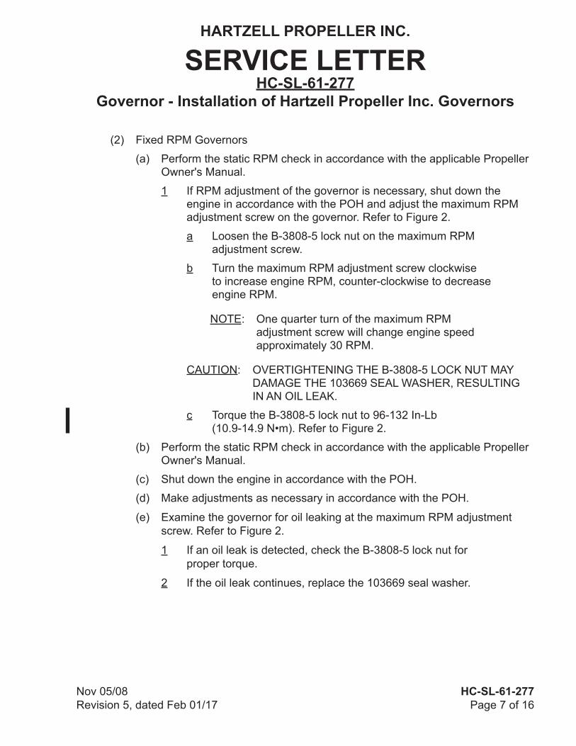
(2) Fixed RPM Governors
(a) Perform the static RPM check in accordance with the applicable Propeller Owner's Manual.
1 If RPM adjustment of the governor is necessary, shut down the engine in accordance with the POH and adjust the maximum RPM adjustment screw on the governor. Refer to Figure 2.
a Loosen the B-3808-5 lock nut on the maximum RPM adjustment screw.
b Turn the maximum RPM adjustment screw clockwise to increase engine RPM, counter-clockwise to decrease engine RPM.
NOTE: One quarter turn of the maximum RPM adjustment screw will change engine speed approximately 30 RPM.
CAUTION: OVERTIGHTENING THE B-3808-5 LOCK NUT MAY DAMAGE THE 103669 SEAL WASHER, RESULTING IN AN OIL LEAK.
c Torque the B-3808-5 lock nut to 96-132 In-Lb (10.9-14.9 N•m). Refer to Figure 2.
(b) Perform the static RPM check in accordance with the applicable Propeller Owner's Manual.
(c) Shut down the engine in accordance with the POH.
(d) Make adjustments as necessary in accordance with the POH.
(e) Examine the governor for oil leaking at the maximum RPM adjustment screw. Refer to Figure 2.
1 If an oil leak is detected, check the B-3808-5 lock nut for proper torque.
2 If the oil leak continues, replace the 103669 seal washer.

HARTZELL PROPELLER INC.
SERVICE LETTERHC-SL-61-277
Governor - Installation of Hartzell Propeller Inc. Governors
Nov 05/08Revision 5, dated Feb 01/17
HC-SL-61-277Page 8 of 16
Maximum RPM Adjust Screw/Lock Nut Locations (Variable RPM Governors Only)Figure 3
Maximum RPM Adjustment Screw/Lock Nut
Maximum RPM Adjustment Screw/Lock Nut
Maximum RPM Adjustment Screw/Lock Nut
cont
rol_
arm
s.ai
Maximum RPM Adjustment Screw/Lock Nut (Screw head orientation is optional)
Maximum RPM Adjustment Screw/Lock Nut Maximum RPM
Adjustment Screw/Lock Nut
RPM Stop

HARTZELL PROPELLER INC.
SERVICE LETTERHC-SL-61-277
Governor - Installation of Hartzell Propeller Inc. Governors
HC-SL-61-277Page 9 of 16
Nov 05/08Revision 5, dated Feb 01/17
C. Operational Checks - In-Flight(1) Variable RPM Governors
CAUTION: DO NOT PERMIT THE PROPELLER TO OVERSPEED DURING THESE OPERATIONAL CHECKS. SIGNIFICANT DAMAGE TO THE ENGINE AND/OR PROPELLER MAY RESULT.
(a) Make a record of the maximum propeller RPM during takeoff acceleration.(b) Climb to a safe altitude and level out the aircraft. (c) Leave the propeller control in the maximum RPM position. (d) Monitor the propeller RPM for 3 to 5 minutes.
1 If the propeller exceeds the maximum RPM:a Using the propeller control lever, reduce the propeller RPM to
achieve the desired maximum RPM.b Leave the propeller control in the newly adjusted maximum
RPM position.c Land the aircraft and shut down the engine.d Remove the aircraft cowling to access the governor.e Adjust the maximum RPM screw so that the screw just touches
the governor control arm stop. Refer to Figure 3.
f Torque the lock nut to 30-36 In-Lb (3.4-4.0 N•m). g Perform an in-flight check to confirm the correct settings.
HARTZELL PROPELLER INC.
SERVICE LETTERHC-SL-61-277
Governor - Installation of Hartzell Propeller Inc. Governors
Nov 05/08Revision 5, dated Feb 01/17
HC-SL-61-277Page 10 of 16
2 If the propeller RPM is below maximum RPM:
a Make a record of the maximum propeller RPM and land the aircraft.
b Remove the aircraft cowling to access the governor.
c Turn the maximum RPM screw counter-clockwise to increase RPM or clockwise to decrease RPM as desired. Refer to Figure 3.
(1) Turn the maximum RPM screw 3 to 4 turns counter-clockwise to increase the maximum RPM approximately 100 RPM.
(2) Turn the maximum RPM screw 3 to 4 turns clockwise to decrease the maximum RPM approximately 100 RPM.
d Torque the lock nut to 30-36 In-Lb (3.4-4.0 N•m).
e Determine maximum RPM change relative to the adjustment of the maximum RPM screw.
f Perform an in-flight check to confirm if the correct maximum RPM has been obtained.

HARTZELL PROPELLER INC.
SERVICE LETTERHC-SL-61-277
Governor - Installation of Hartzell Propeller Inc. Governors
HC-SL-61-277Page 11 of 16
Nov 05/08Revision 5, dated Feb 01/17
(2) Fixed RPM Governors
CAUTION: DO NOT PERMIT THE PROPELLER TO OVERSPEED DURING THESE OPERATIONAL CHECKS. SIGNIFICANT DAMAGE TO THE ENGINE AND/OR PROPELLER MAY RESULT.
(a) Make a record of the maximum propeller RPM during takeoff acceleration.
(b) Climb to a safe altitude and level out the aircraft.
(c) Monitor the propeller RPM for 3 to 5 minutes.
(d) If RPM adjustment is necessary:
1 Land the aircraft and shut down the engine in accordance with the POH.
2 Loosen the B-3808-5 lock nut on the maximum RPM adjustment screw. Refer to Figure 2.
3 Turn the maximum RPM adjustment screw clockwise to increase engine RPM, counter-clockwise to decrease engine RPM. Refer to Figure 2.
NOTE: One quarter turn of the maximum RPM adjustment screw will change engine speed approximately 30 RPM.
CAUTION: OVERTIGHTENING THE B-3808-5 LOCK NUT MAY DAMAGE THE 103669 SEAL WASHER, RESULTING IN AN OIL LEAK.
4 Torque the B-3808-5 lock nut to 96-132 In-Lb (10.9-14.9 N•m). Refer to Figure 2.
(e) Determine the maximum RPM change relative to the adjustment of the maximum RPM adjustment screw.
(f) Perform an in-flight check to verify proper adjustment of the maximum RPM.
(g) Examine the governor for oil leaking at the maximum RPM adjustment screw. Refer to Figure 2.
1 If an oil leak is detected, check the B-3808-5 lock nut for proper torque.
2 If the oil leak continues, replace the 103669 seal washer.

HARTZELL PROPELLER INC.
SERVICE LETTERHC-SL-61-277
Governor - Installation of Hartzell Propeller Inc. Governors
Nov 05/08Revision 5, dated Feb 01/17
HC-SL-61-277Page 12 of 16
Lock Nut
Washer
Cap Head Screw
Control Lever
RPM Stop
Return Spring
Governor Head
Control Lever AdjustmentFigure 4
Control Shaft
TPI-M
B-0
147
HARTZELL PROPELLER INC.
SERVICE LETTERHC-SL-61-277
Governor - Installation of Hartzell Propeller Inc. Governors
HC-SL-61-277Page 13 of 16
Nov 05/08Revision 5, dated Feb 01/17
D. Control Lever Adjustment
(1) S-1 and S-4 Series Governors with Top Mounted Control Levers
(a) Coarse Adjustment of the Control Lever - Refer to Figure 4
1 Remove the lock nut and washer.
CAUTION: DO NOT REMOVE THE RPM STOP OR THE RETURN SPRING. IF THE RPM STOP OR THE RETURN SPRING ARE REMOVED, THE GOVERNOR MUST BE RETURNED TO HARTZELL PROPELLER INC. OR A SERVICE FACILITY AUTHORIZED TO REPAIR MECHANICALLY ACTUATED GOVERNORS TO VERIFY THE RPM SETTING.
2 Remove the control lever from the control shaft.
3 Install the control lever on the control shaft in the desired position.
a The control lever can be turned over for an additional 15 degrees of coarse adjustment.
4 Install the washer and the lock nut.
a Torque the lock nut to 72-96 In-Lbs (8.2-10.8 N•m).
(b) Fine Adjustment of the Control Lever - Refer to Figure 4
1 For Governors Without Safety Wire on the Cap Head Screws:
a Loosen, but do not remove the six cap head screws that attach the governor head.
b Rotate the governor head until the control lever is at the desired angle.
c Remove one cap head screw from the governor head.
d Clean the cap head screw to remove any dried locking compound.
e Apply threadlocking adhesive CM116 to the threads of the cap head screw.
f Install the cap head screw into the governor head.
g Torque the cap head screw to 21-25 In-Lbs (2.4-2.8 N•m).
h Repeat steps 3.D.(1)(b)1 c through 3.D.(1)(b)1 g for the five remaining cap head screws.
HARTZELL PROPELLER INC.
SERVICE LETTERHC-SL-61-277
Governor - Installation of Hartzell Propeller Inc. Governors
Nov 05/08Revision 5, dated Feb 01/17
HC-SL-61-277Page 14 of 16
(c) For Governors With Safety Wire on the Cap Head Screws:
1 Remove the safety wire from the six cap head screws that attach the governor head.
2 Loosen, but do not remove the six cap head screws.
3 Rotate the governor head until the control lever is at the desired angle.
4 Torque the six cap head screws to 21-25 In-Lbs (2.4-2.8 N•m).
5 Safety wire the six cap head screws in accordance with NASM 33540.
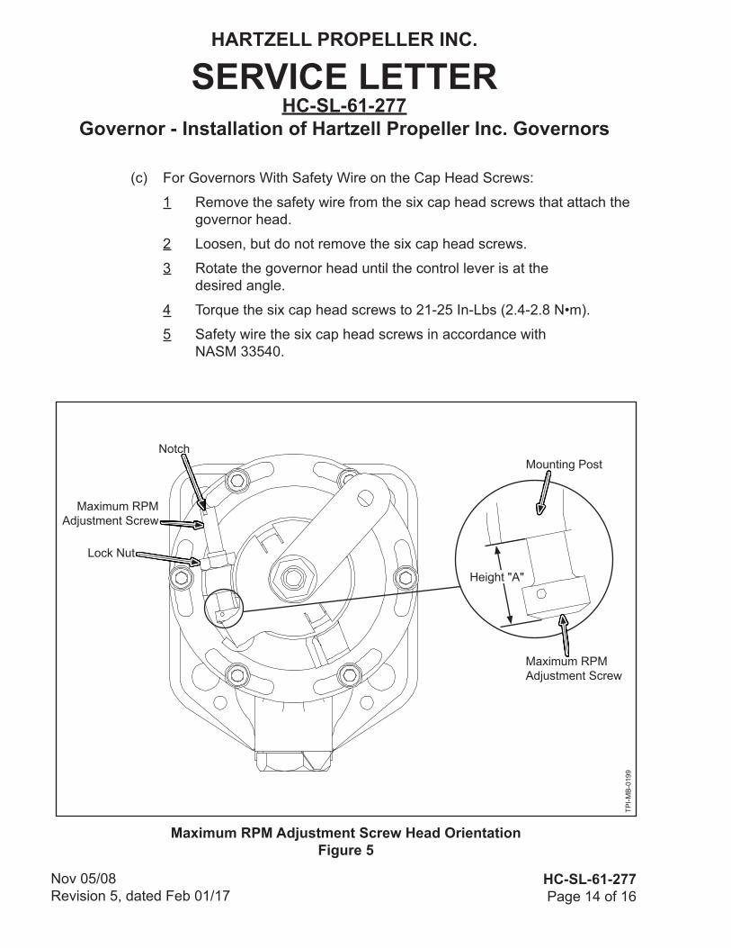
Maximum RPM Adjustment Screw Head OrientationFigure 5
Notch
Lock Nut
Maximum RPM Adjustment Screw
Height "A"
Maximum RPM Adjustment Screw
TPI-M
B-0
199
Mounting Post

HARTZELL PROPELLER INC.
SERVICE LETTERHC-SL-61-277
Governor - Installation of Hartzell Propeller Inc. Governors
HC-SL-61-277Page 15 of 16
Nov 05/08Revision 5, dated Feb 01/17
E. Maximum RPM Adjustment Screw Head Orientation
(1) Variable RPM S-1 Series Governors Only
NOTE: Maximum RPM adjustment screws that do not have a slot in the threaded portion of the screw can be installed with the head on either side of the mounting post. Refer to Figure 5.
(a) Measure the height "A" of the maximum RPM adjustment screw that touches the RPM stop. Refer to Figure 5.
1 Make a record of the height measurement.
(b) Remove the lock nut and the maximum RPM adjustment screw.
(c) Install the maximum RPM adjustment screw head in the desired orientation to the height recorded in step 3.E.(1)(a).
(d) Install the lock nut on the opposite side of the maximum RPM adjustment screw head.
1 Torque the lock nut to 30-36 In-Lbs (3.4-4.0 N•m).
F. Contact Information
Hartzell Propeller Inc.Attn.: Hartzell Propeller Inc. Product SupportOne Propeller PlacePiqua, Ohio 45356-2634 USAPhone: (001) 937.778.4379 Fax: (001) 937.778.4215E-mail: [email protected]

HARTZELL PROPELLER INC.
SERVICE LETTERHC-SL-61-277
Governor - Installation of Hartzell Propeller Inc. Governors
Nov 05/08Revision 5, dated Feb 01/17
HC-SL-61-277Page 16 of 16
(This page is intentionally blank.)


