
750-819 LON PFC
Configuring & Networking
Application note A2024_01
English Version 1.0.0
Archive
d Doc
umen
t

2 • General
Copyright © 2002 by WAGO Kontakttechnik GmbH All rights reserved.
WAGO Kontakttechnik GmbH Hansastraße 27 D-32423 Minden
Phone: +49 (0) 571/8 87 – 0 Fax: +49 (0) 571/8 87 – 1 69
E-Mail: [email protected]
Web: http://www.wago.com
Technical Support Phone: +49 (0) 571/8 87 – 5 55 Fax: +49 (0) 571/8 87 – 85 55
E-Mail: [email protected]
Every conceivable measure has been taken to ensure the correctness and com-pleteness of this documentation. However, as errors can never be fully ex-cluded we would appreciate any information or ideas at any time.
We wish to point out that the software and hardware terms as well as the trademarks of companies used and/or mentioned in the present manual are generally trademark or patent protected.
Application note A2024_01
Archive
d Doc
umen
t

Table of Contents • 3
TABLE OF CONTENTS
1 Important comments ................................................................................. 4 1.1 Legal principles............................................................................................ 4 1.1.1 Copyright .......................................................................................... 4 1.1.2 Personnel qualification ..................................................................... 4 1.1.3 Intended use...................................................................................... 4 1.2 Range of validity.......................................................................................... 5
2 Description.................................................................................................. 6
3 Reference Material .................................................................................... 7 3.1 Network Variable Addressing ................................................................... 10 3.1.1 Inputs: Write from Network to PFC ............................................... 10 3.1.2 Outputs: Write from PFC to Network ............................................ 10 3.1.3 PFC Module Addressing ................................................................ 11 3.2 Lets Write A Program................................................................................ 12 3.3 819 test program ........................................................................................ 14 3.3.1 SAVE THE PROJECT: .................................................................. 15 3.3.2 Download Program to the 750-819 PFC ........................................ 17 3.4 Configuring TOPLON PRIO ..................................................................... 19 3.4.1 Configure I/O.................................................................................. 26 3.4.2 Configure SNVT Types to NVI & NVO........................................ 27 3.4.3 Configure NVI & NVO to Network Variables............................... 29 3.4.4 Monitor the Data............................................................................. 34 3.5 Putting it all Together ................................................................................ 35 3.5.1 Apply the following:....................................................................... 36 3.6 ADVANCED LON PEER-TO-PEER ....................................................... 37 3.6.1 Configure the 819 Node ................................................................. 38 3.6.2 Configure the 319 Node ................................................................. 40 3.6.3 Binding Nodes Together................................................................. 41 3.6.4 Test the Digital Bindings................................................................ 44 3.6.5 Bind Analogs and the PFC Program............................................... 45 3.6.6 Reviewing the NV configuration.................................................... 45 3.7 Application for a Lon Network.................................................................. 47
Application note A2024_01
Archive
d Doc
umen
t

4 •
1 Important comments To ensure fast installation and start-up of the units described in this manual, we strongly recommend that the following information and explanation is carefully read and adhered to.
1.1 Legal principles
1.1.1 Copyright
This manual is copyrighted, together with all figures and illustrations con-tained therein. Any use of this manual which infringes the copyright provi-sions stipulated herein, is not permitted. Reproduction, translation and elec-tronic and photo-technical archiving and amendments require the written con-sent of WAGO Kontakttechnik GmbH. Non-observance will entail the right of claims for damages.
1.1.2 Personnel qualification
The use of the product detailed in this manual is exclusively geared to special-ists having qualifications in PLC programming, electrical specialists or per-sons instructed by electrical specialists who are also familiar with the valid standards. WAGO Kontakttechnik GmbH declines all liability resulting from improper action and damage to WAGO products and third party products due to non-observance of the information contained in this manual.
1.1.3 Intended use
For each individual application, the components supplied are to work with a dedicated hardware and software configuration. Modifications are only admit-ted within the framework of the possibilities documented in the manuals. All other changes to the hardware and/or software and the non-conforming use of the components entail the exclusion of liability on part of WAGO Kon-takttechnik GmbH.
Please direct any requirements pertaining to a modified and/or new hardware or software configuration directly to WAGO Kontakttechnik GmbH.
Application note A2024_01 Created by T. Lenz 4
Archive
d Doc
umen
t

• 5
1.2 Range of validity This application note is based on the stated hardware and software of the spe-cific manufacturer as well as the correspondent documentation. This applica-tion note is therefore only valid for the described installation.
New hardware and software versions may need to be handled differently. Please note the detailed description in the specific manuals.
Application note A2024_01 Created by T. Lenz
5
Archive
d Doc
umen
t

6 •
2 Description This document is to be used with the example node from the document PFC 101 Get Started Quick. The following describes Configuring and networking the example node using the software and equipment listed below.
Networker 2.0 Software.
TOPLON PRIO Plug-in.
XLON DONGLE (WAGO Part#759-344 Parallel Port Adapter ).
750-819 PFC & 750-319 Buscoupler.
Install Networker 2 configuration Software.
Install TOPLON PRIO
Install the Driver for the Communications adapter.
Install WAGO-PRO32 IEC 6-1131 Programming software
For other details about WAGO TOPLON & 750- 819 please refer to the WAGO TOPLON Users Manual 759-123/000-001. The Files and Programs in this document can be downloaded from the web site www.wagotoplon.com
Application note A2024_01 Created by T. Lenz 6
Archive
d Doc
umen
t

• 7
3 Reference Material 3.1 Network & Configure the LON Network
1: WAGO has Library files for LON that can be loaded into WAGO-Pro32. These Library files have a selection of function blocks to help with building automation functions.
Save these files to C:\Program Files\WAGO_Pro32\LIB2
2: Save the Program Template_750_819.PRO to
C:\Program Files\WAGO_PRO32\Projects
Template_750_819.PRO program was written using FBD
(Function Block Diagram)
3: Start WAGO-PRO 32 and load the program Template_750_819.
(The next steps 4-10 of converting from FBD to LD is optional. )
(It is the programmers choice of FBD or LD )
(If the program is not to be converted from FBD to LD then skip to Step 11)
4: Template_750_819 was written in FBD. Programs in these examples are documented and written in Ladder Logic. To keep the documents consistent the Template program will be converted to LD (Ladder Logic)
5: Once Template_750_819 is loaded the program must be checked
Click on Projects \ Check
Wago-Pro32 checks the program. One error will be displayed at first, No logic has been entered at this time, so this error is ok to continue.
Application note A2024_01 Created by T. Lenz
7
Archive
d Doc
umen
t

8 •
6: Click on PLC_PRG to the left side of WAGO-PRO to highlight
7: Right Click on PLC_PRG to bring up the Object Window
8: Select Convert Object
9: Then select LD for Ladder Logic
10: Then Double click on PLC_PRG to get the Ladder Logic Editor Window to start programming. (Do not change New POU name from PLC_PRG)
(lon2) (lon3)
11: Save this program under a new file name. The New file name should be the name you choose for the Project .
Using File/Save As, Save under a new file name.
(Example Program was saved as 819test.pro)
NOTE: Do not save over Template_750_819. Store this file in a safe place. This program will be used again when starting a new project.
Application note A2024_01 Created by T. Lenz 8
Archive
d Doc
umen
t

• 9
Wago-Pro32 Template_750_819 (Lon1)
Template_750_819.PRO does not have any logic written, only Variables are declared. These Variables arecalled PLC Network Variables. (These are not LON Network Variables)
Network Variables are locations in the PFC memory:
%Ixxx Data is passed from the LON network to the PFC Input Memory.
%Qxxx is PFC Output Memory to pass Data to the LON network.
Application note A2024_01 Created by T. Lenz
9
Archive
d Doc
umen
t
10 •
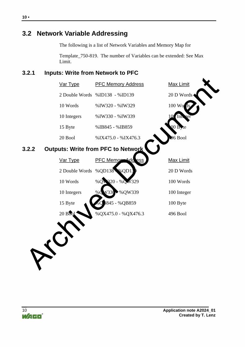
3.2 Network Variable Addressing The following is a list of Network Variables and Memory Map for
Template_750-819. The number of Variables can be extended: See Max Limit.
3.2.1 Inputs: Write from Network to PFC
Var Type PFC Memory Address Max Limit
2 Double Words %ID138 - %ID139 20 D Words
10 Words %IW320 - %IW329 100 Words
10 Integers %IW330 - %IW339 100 Integer
15 Byte %IB845 - %IB859 100 Byte
20 Bool %IX475.0 - %IX476.3 496 Bool
3.2.2 Outputs: Write from PFC to Network
Var Type PFC Memory Address Max Limit
2 Double Words %QD138 - %QD139 20 D Words
10 Words %QW320 - %QW329 100 Words
10 Integers %QW330 - %QW339 100 Integer
15 Byte %QB845 - %QB859 100 Byte
20 Bool %QX475.0 - %QX476.3 496 Bool
Application note A2024_01 Created by T. Lenz 10
Archive
d Doc
umen
t

• 11
3.2.3 PFC Module Addressing
1: Analogs and Specialty modules are addressed first
2: Digital modules follow after the Analog & Specialty modules
3: PFC Addressing is sequential
4: PFC Addressing starts at word 0
750-819 PFC I/O module Addressing is as follows
Inputs Addrs Variables Output Addrs Variables
750-467 %IW0 AICHAN1 750-550 %QW0 AOCHAN1
%IW1 AICHAN2 %QW1 AOCHAN2
750-402 %IX2.0 INPUT0 750-516 %QX2.0 OUTPUT0
%IX2.1 INPUT1 %QX2.1 OUTPUT1
%IX2.2 INPUT2 %QX2.2 OUTPUT2
%IX2.3 INPUT3 %QX2.3 OUTPUT3
750-516 %QX2.4 OUTPUT4
%QX2.5 OUTPUT5
%QX2.6 OUTPUT6
%QX2.7 OUTPUT7
750-516 %QX2.8 OUTPUT8
%QX2.9 OUTPUT9
%QX2.10 OUTPUT10
%QX2.11 OUTPUT11
750-600 End Module (No Memory Allocation needed)
Application note A2024_01 Created by T. Lenz
11
Archive
d Doc
umen
t

12 •
3.3 Lets Write A Program
(lon4)
Application note A2024_01 Created by T. Lenz 12
Archive
d Doc
umen
t

• 13
(lon5)(lon6)
Application note A2024_01 Created by T. Lenz
13
Archive
d Doc
umen
t

14 •
3.4 819 test program Rung 1:
INPUT1 is the first Input from the digital input module.
OUTPUT1 is the first Output from the first digital output module.
When INPUT1 is On, OUTPUT1 turns On. The PFC has full control of rung 1.
Rung 2:
INPUT2 is the second Input from the digital input module.
O_Bit1 is the first Bool PLC Network Variable Output. When INPUT2 is ON, O_Bit1 will turn on sending this bit out to the LON network.
Rung 2,3 & 4 perform the same function.
Rung 5: I_Bit1 is the first Bool PLC Network Variable Input. Output2 is the second Output on the output module. When the Network Variable I_Bit1 is on Output2 will turn on. Rung 5,6 & 7 perform the same function Rung 8: I_W1 is the first Input Word data PLC Network Variable. AOCH1 is addressed to the first Analog Output Channel. When I_W1 has values 0 – 32767 written, The values are MOVED to Analog Output 1
Rung 9: O_W1 is the first output Word data PLC Network Variable. AICH1 is the first Analog Input channel. Analog Output CH1 is wired to Analog Input CH1. Data is sent from the LON Network variable to the Analog output module. The Analog Input module gets the 0-10Vdc signal and then moves the data to O_W1 Network Variable. The data of the Analog input module should follow closely to the data of the Analog output module.
Application note A2024_01 Created by T. Lenz 14
Archive
d Doc
umen
t

• 15
3.4.1 SAVE THE PROJECT:
The Program needs to be saved with some options turned on for configuring TOPLON Prio.
1: Click on Project Select Options
(lon7)
Application note A2024_01 Created by T. Lenz
15
Archive
d Doc
umen
t
16 •
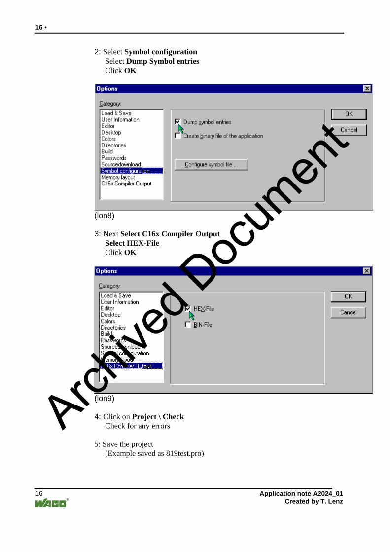
2: Select Symbol configuration Select Dump Symbol entries Click OK
(lon8) 3: Next Select C16x Compiler Output Select HEX-File Click OK
(lon9) 4: Click on Project \ Check Check for any errors 5: Save the project (Example saved as 819test.pro)
Application note A2024_01 Created by T. Lenz 16
Archive
d Doc
umen
t
• 17
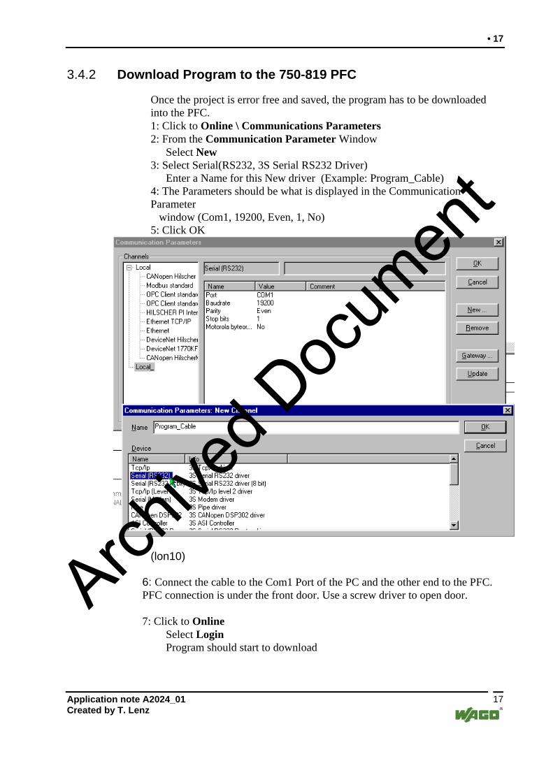
3.4.2 Download Program to the 750-819 PFC
Once the project is error free and saved, the program has to be downloaded into the PFC. 1: Click to Online \ Communications Parameters 2: From the Communication Parameter Window Select New 3: Select Serial(RS232, 3S Serial RS232 Driver) Enter a Name for this New driver (Example: Program_Cable) 4: The Parameters should be what is displayed in the Communication Parameter window (Com1, 19200, Even, 1, No) 5: Click OK
(lon10)
6: Connect the cable to the Com1 Port of the PC and the other end to the PFC. PFC connection is under the front door. Use a screw driver to open door. 7: Click to Online Select Login Program should start to download
Application note A2024_01 Created by T. Lenz
17
Archive
d Doc
umen
t

18 •
8: Once the Program is downloaded Run the program by selecting the Run Icon Left of the Stop Icon
(lon11) Once the Program is written and working correctly, lets move on to configure TOPLON PRIO.
OPTION: Any unused I_DW, I_Byte, I_W, I_int, I_bit, Q_DW, Q_Byte, Q_W, Q_int , Q_bit or unused variables can be deleted. This will help to keep things clear later in configuring.
Application note A2024_01 Created by T. Lenz 18
Archive
d Doc
umen
t

• 19
3.5 Configuring TOPLON PRIO
Start Networker 2 Lon Configuration software 1: Click on File \ New and Create a New Network Name: Enter name for the New Network (Example:819test) Path: Leave at C:\DB\ Interface: Select interface to be used
(XLON Dongle Driver was loaded for this example) Domainlength: leave at 1 Byte Domain ID: leave at 00
Click Apply \ OK
(lon12) 2: Networker 2 Main status window will create and open the new network 819test. The XLON Dongle will be initialized and started.
Application note A2024_01 Created by T. Lenz
19
Archive
d Doc
umen
t

20 •
3: WAGO TOP LON PRIO needs to be Registered in the Network2 Software. Click on View \ Plugins
(lon16) 4: Select WAGO TOPLON-PRIO and Install
(lon15)
Application note A2024_01 Created by T. Lenz 20
Archive
d Doc
umen
t

• 21
5: From this window select Prio 26_26 and Rio 26_26 Click Continue
(lon17) 6:Click on Subsystem_1 to highlight 7: Next Click on the ICON that looks like an IC Chip to Create a Device
(lon13)
Application note A2024_01 Created by T. Lenz
21
Archive
d Doc
umen
t

22 •
8: Add New Device window will be displayed Name: Enter Device name (Example: 750_819PFC) Channel: Select Channel_1 Devicetemplate: Select PRIO_26_26_01 Neuron ID: Press the Service PIN on the 819 or enter in the ID. Pressing the Service Switch may automatically insert Channel, Devicetemplate, and Neuron ID Click Apply \ OK
(lon14)
Application note A2024_01 Created by T. Lenz 22
Archive
d Doc
umen
t

• 23
9: If your window looks like the following, The software does not know who the Node is. Right click on the Device (750_819PFC) Select Replace or Commission A window will be displayed with the Neuron ID.
If this is correct for this device click OK If this is not correct Press the Service Pin again to get the ID.
(lon18) If the error still exists then Right click on the node and Upload Application. The Application can be found at: C:\Program Files\Wago Kontakttechnik\WAGO TOPLON-PRIO\Templates\PRIO_26_26_01.APB Download this application.
Application note A2024_01 Created by T. Lenz
23
Archive
d Doc
umen
t

24 •
10: To start TOPLON PRIO Right Click on the Device Cursor down to Plugins Select TOPLON PRIO Configuration
(lon19)
Application note A2024_01 Created by T. Lenz 24
Archive
d Doc
umen
t

• 25
11: The following window will be displayed showing that PRIO is starting
(LON20)
(lon23) WAGO TopLON PRIO Main Window
Application note A2024_01 Created by T. Lenz
25
Archive
d Doc
umen
t

26 •
3.5.1 Configure I/O
12: When PRIO is started the first window to be displayed is the Hardware Configuration. Select the modules in order as they are placed in the Node Select Close (Continue) when finished.
(lon21) Note: If PRIO is displayed in German the text can be changed to English. From the Main window
Select Extra \ Options \ Spreche Select English Select Apply \ OK This will change the language to English
Application note A2024_01 Created by T. Lenz 26
Archive
d Doc
umen
t

• 27
13: Next the Symbol file from WAGO-PRO32 has to be loaded into TOPLON PRIO. Click on WAGO-IO-PRO Select Open SYM FILE The SYM file can be found in the following Directory C:\Program Files\WAGO-PRO32\Projects Select the Sym file of the Project name and click Open (Example: 819test.sym)
(lon24)
3.5.2 Configure SNVT Types to NVI & NVO
14: Next the software Variables need to be configured. In the world of LON there are variables called NV (Network Variables). SNVT’s are (Standard Network Variable Type) NVI is a Network Variable Input NVO is a Network Variable Output SNVT’s are assigned to NVI & NVO. This tells the NV what Variable Type it will be (SNVT_Switch, SNVT_Word,SNVT_Temp…) ( SEE: ECHILON for Variable Type Definition) ( Also SEE WAGO TOPLON PRIO User Manual ) 15: Click on Configuration \ Software and the NVI window will be displayed Click on Nvi00 to highlight this row. Click on SNVT_str_asc to change the selection. Click on the down arrow to get SNVT selection. Select SNVT_switch each digital Input. (4 Inputs in this example)
Nvi05 will be configured as SNVT_switch for I_W1(%IW320) in the PFC.
Nvi06 will be configured as SNVT_switch for I_W2(%IW321) in the PFC.
Application note A2024_01 Created by T. Lenz
27
Archive
d Doc
umen
t

28 •
(lon22)
16: Click on NVO’s and do the same in step 14 for each of the Outputs (This example has 12 inputs) NVO13 will be configured as SNVT_switch for O_W1(%QW320) in the PFC NVO14 will be configured as SNVT_switch for O_W2(%IW321) in the PFC
Application note A2024_01 Created by T. Lenz 28
Archive
d Doc
umen
t

• 29
3.5.3 Configure NVI & NVO to Network Variables
17: Next the PLC Network Variables have to be assigned to a NVI and NVO. Click on Bool_Ins to select this configuration Window. Cursor to Connected and click into the PLC_PRG.O_Bitxx row. Select the NVO to be assigned to the PLC_PRG Bit.
(lon25)
Application note A2024_01 Created by T. Lenz
29
Archive
d Doc
umen
t

30 •
18: Once the NVO has been selected the SNVT values have to be assigned. The Select Element of the NVO window will be displayed for SNVT_Switch. Click on SNVT_switch to Highlight and click OK.
(Ion26) 19: Change the following ON Value Window.
Change the Value from 255 to 200 Change the Value of State from 127 to 1 Click OK
(lon27)
Application note A2024_01 Created by T. Lenz 30
Archive
d Doc
umen
t

• 31
20: Change the Value of the OFF Value to the following Change Value to 0 Change State to 0 Click OK
(lon28) 21: Repeat Step 17-20 as needed for each of the PLC_PRG bits. This example is only using PLC_PRG.O_Bits0 – Bits3 of Bool_In. 22: Click on Bool_OUT’s and do the same for Steps 17-20 for Bool_OUT’s. This Example is only using PLC_PRG.I_Bits0 - Bits3 of Bool_Out’s. On Value = 200, State Value = 1. Off Value = 0, State Value = 0.
Application note A2024_01 Created by T. Lenz
31
Archive
d Doc
umen
t

32 •
23: Once the Bool_In & Bool_Out are configured, Select VAR_Ins. Double Click on Connect for PLC_PRG.O_W1. Click on the Down arrow and select NVO12[SNVT_switch]. PLC_PRG.O_W2 = NVO13[SNVT_switch].
(lon29)
Application note A2024_01 Created by T. Lenz 32
Archive
d Doc
umen
t

• 33
24: The Next window is displayed for SNVT_switch to configure the Analogs. Click on value to scale the register value. Click OK
(lon30) 25: Scale the High Limit = 32767 and NV = 200 Scale the Low Limit = 0 and NV = 0
(lon31) 26: Repeat as needed for the other channel. Repeat the configuration for the Var_Outs using NVi04 & NVi05 27: When all the NV’s for Bool_In/Out & Var_In/Out are configured. Click on OK to the Right.
When the APPLY window is displayed Click on YES to Update the 819.
Application note A2024_01 Created by T. Lenz
33
Archive
d Doc
umen
t

34 •
28: If everything is correct the NV Configuration window will close TOPLON Prio Main Window Is Displayed The Device ICON in Networker2, under Subsystem1 will look like the following. This shows the Device is online and all parameters were updated. If the device Icon does not look like this try re-downloading or do a replace from a right mouse click to clear the error.
(lon32)
3.5.4 Monitor the Data
29: Select the NV Browser from the Main tool bar Prio will Open the NV Browser window and read the PFC Network variable values.
(lon33)
Application note A2024_01 Created by T. Lenz 34
Archive
d Doc
umen
t

• 35
30: The NV Browser window will send / receive the values of the Network Variables. Click on NVI00 Row and click on the Monitoring column. Click on the down arrow and then Polled 0.5s (or how fast to Poll Variable) Note: Polled has to be selected for each NVI & NVO to monitor the I/O Data.
(lon34)
3.6 Putting it all Together
(lon35) The NV Browser should be polling to Monitor the variables. Lon divides the value number in half, This is why the 200 was used in the NV configuration and 100.0 1 is displayed. In the above example, nvi00 has been configured and programmed in the PFC to turn On/Off the 2nd Digital output in the PFC.
Application note A2024_01 Created by T. Lenz
35
Archive
d Doc
umen
t

36 •
3.6.1 Apply the following:
Digital Output: At the nvi00 row, Value column Click to Highlight 0.0 0 and change to 100.0 1. This will Turn ON Output 2. Click to Highlight Value and change to 0.0 0. This will Turn Off Output 2. (Same will apply to the next 3 digital outputs ) Analog Outputs: At the nvi04 row, Value column Click to Highlight 0.0 0 and change to 50.0 1 This will send a 50% signal to I_W1 in the PFC. 50% on the LON side = 16000 on the PFC side for an Analog number. The PFC is Programmed to move I_W1 to AOCHAN1 to control the first Analog Output Channel from 0-32767.
(lon36)
Digital Inputs: At the nvo00 row,Value column Digital Input2 is monitored. When Input 2 is Off the Value is 0.0 0. When Input 2 is On the Value is 100.0 1. Analog Inputs: At the nvo12 row, Value column Analog Input Channel1 is monitored The signal that was sent to the Analog output was 50%. The Analog Input module is wired to read the Analog output module. AICHAN1 moves the values 0-32767 to O_W1 to send to the Lon network as a % value. In the NV Browser the value of nvo12 is about 50%. The Analog input will follow the Analog output.
Application note A2024_01 Created by T. Lenz 36
Archive
d Doc
umen
t

• 37
3.7 Advanced LON Peer-To-Peer
In this example The 750-819 will communicate to the 750-319 to control I/O. ( Refer to top of document for help. Most steps are repeated in Configuring) 1:Start a New Network called 819_319 in Networker 2. 2: Click on View and Load TOPLON-PRIO into Networker 2 3: Add 2 New Devices to the Subsystem. Right click on the Subsystem Icon. Select NEW. Select New Device. 4: The Add Device window will be displayed. Name: 819 (for the 819) / 319 (for the 319). Press Service Pin and the following info should be displayed. Channel: Select Channel 1. Device Template: PRIO_26_26(819) RIO_26_26(319). Neuron ID: (Will be different for each node).
(lon37)
Application note A2024_01 Created by T. Lenz
37
Archive
d Doc
umen
t

38 •
The Network Explorer window should look as follows with 2 Nodes under the Subsystem:
(lon38)
3.7.1 Configure the 819 Node
5: Right Click on the 819 Node. Select Plugins and start TOPLON-PRIO. 6: Configure the Hardware. Select and Add the modules as they are located in the 819 Node. 7: Load the SYM file from the 819test PFC Program.
(lon24)
Configure the NVI & NVO to the SNVT type. Configure the DI, DO, AI & AO.
819 NVI Configuration
(lon39)
Application note A2024_01 Created by T. Lenz 38
Archive
d Doc
umen
t

• 39
819 NVO Configuration
(lon40) 819 Bool_In Configuration
(lon41) 819 Bool_out Configuration
(lon42)
Application note A2024_01 Created by T. Lenz
39
Archive
d Doc
umen
t

40 •
819 Var_IN Configuration
(lon43) 819 Var_Out Configuration
(lon44) 3.7.2 Configure the 319 Node
Connect Channel 1 of the Analog Output to Channel 1 of the Analog Input of the 319 Node. 8: Right Click on the 319 Node . Select Plugins and start TOPLON-PRIO. 9: Configure the Hardware. Select and Add the modules as they are located in the 319 Node. 10: Configure the NVI & NVO to the SNVT type. Configure the DI,DO,AI & AO.
319 NVI Configuration
(lon45) 319 NVO Configuration
(lon46) 319 Bool_In Configuration (Create your own name in the Name Column)
Application note A2024_01 Created by T. Lenz 40
Archive
d Doc
umen
t

• 41
(lon47) 319 Bool_Out Configuration (Create your own name in the Name Column)
(lon48) 319 Var_IN Configuration (Create your own name in the Name Column)
(lon49) 319 Var_Out Configuration (Create your own name in the Name Column)
(lon50) 3.7.3 Binding Nodes Together
With Lon it is possible to send data from one node to another node, this is called Peer-to-Peer communications. Binding is configuring a Network Variable from one node to a Network Variable in another node creating a lasystem communicating together. The Network Variables are configured in the 750-819 and 750-319 and can now be bound together.
rge
1: Minimize WAGO TOPLON-PRIO so only Network explorer is displayed. Click on the 819 or the 319 Icon to the left. This displays the list of NVI & NVO for each device. These will be used to assign the bindings.
Application note A2024_01 Created by T. Lenz
41
Archive
d Doc
umen
t

42 •
(lon51)
2: Next start the Binding manager Click on View Select Bindingmanager
(lon52)
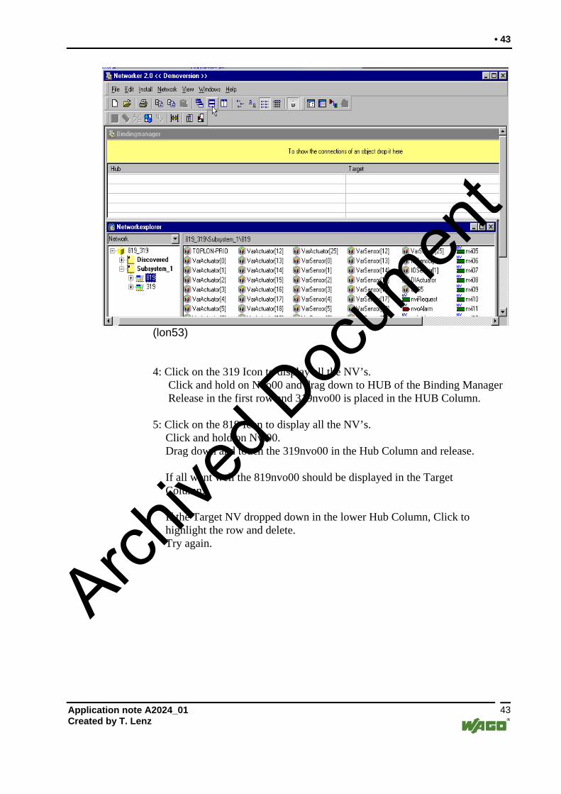
3: Once the Binding Manager is open, it is recommended to TILE the windows because the next procedure will need to drag and drop objects. This example displays Window TILE HORIZONTAL. If the LOG window is tiled, Minimize this window and re-tile.
Application note A2024_01 Created by T. Lenz 42
Archive
d Doc
umen
t
• 43
(lon53)
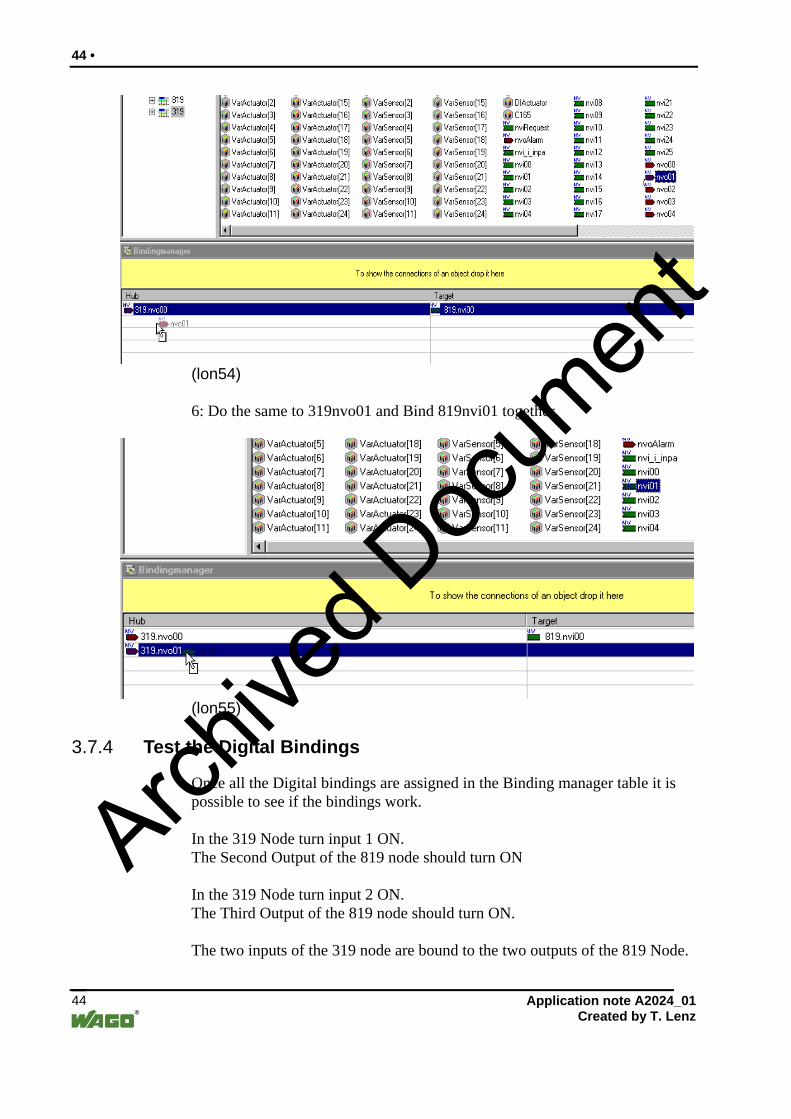
4: Click on the 319 Icon to display all the NV’s. Click and hold on Nvo00 and drag down to HUB of the Binding Manager
Release in the first row and 319nvo00 is placed in the HUB Column. 5: Click on the 819 Icon to display all the NV’s.
Click and hold on Nvi00. Drag down and touch the 319nvo00 in the Hub Column and release.
If all went well the 819nvo00 should be displayed in the Target Column. If the Target NV dropped down in the lower Hub Column, Click to highlight the row and delete. Try again.
Application note A2024_01 Created by T. Lenz
43
Archive
d Doc
umen
t
44 •
(lon54) 6: Do the same to 319nvo01 and Bind 819nvi01 together.
(lon55)
3.7.4 Test the Digital Bindings
Once all the Digital bindings are assigned in the Binding manager table it is possible to see if the bindings work. In the 319 Node turn input 1 ON. The Second Output of the 819 node should turn ON In the 319 Node turn input 2 ON. The Third Output of the 819 node should turn ON. The two inputs of the 319 node are bound to the two outputs of the 819 Node.
Application note A2024_01 Created by T. Lenz 44
Archive
d Doc
umen
t
• 45
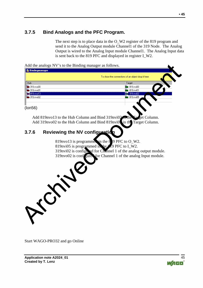
3.7.5 Bind Analogs and the PFC Program.
The next step is to place data in the O_W2 register of the 819 program and send it to the Analog Output module Channel1 of the 319 Node. The Analog Output is wired to the Analog Input module Channel1. The Analog Input data is sent back to the 819 PFC and displayed in register I_W2.
Add the analogs NV’s to the Binding manager as follows.
(lon56)
Add 819nvo13 to the Hub Column and Bind 319nvi02 in the Target Column. Add 319nvo02 to the Hub Column and Bind 819nvi05 in the Target Column.
3.7.6 Reviewing the NV configuration
819nvo13 is programmed in the 819 PFC to O_W2. 819nvi05 is programmed in the 819 PFC to I_W2. 319nvi02 is configured for Channel 1 of the analog output module. 319nvo02 is configured for Channel 1 of the analog Input module.
Start WAGO-PRO32 and go Online
Application note A2024_01 Created by T. Lenz
45
Archive
d Doc
umen
t

46 •
(lon57)
Double Click on the variable O_W2. A Write Variable window will be displayed.
(lon58) Enter the value 16000 in the New Value box. Click OK. Press Ctrl-F7 to write the value to the PFC Memory. The value will be sent from the 819 PFC to the Analog Output of the 319. The Analog output sends the 0-10Vdc signal to the analog input module. The Analog input module will send the value back to the 819 PFC and displayed in variable I_W2.
Application note A2024_01 Created by T. Lenz 46
Archive
d Doc
umen
t

• 47
3.8 Application for a Lon Network
The Wago 750-819 can control the local I/O through the program. Program Data can be passed to a 750-319 or another 750-819 to do remote control. The 750-819 can be a master in a network controlling other nodes, but can receive data from other nodes to take action in the program and send commands through the network. With the 750-819 PFC and WAGO-PRO32, a high level language like Neuron C can be eliminated. Writing programs in Ladder logic, Function Block, Structured Text or the other choices in WAGO-PRO32, it makes it easy for people to understand. The program can be viewed and changed through WAGO-PRO32 and data variables can be monitored as the program is running. WAGO’s flexible choice of Digital, Analog and Specialty I/O modules makes a tailored combination for project. WAGO’s 750-819 Programmable Field Controller makes programming easy to use and understand and maintain without a Neuron C programming degree. WAGO TOPLON: ” Open Architecture for Open Solutions ”.
Application note A2024_01 Created by T. Lenz
47
Archive
d Doc
umen
t

WAGO Kontakttechnik GmbH Postfach 2880 • D-32385 Minden Hansastraße 27 • D-32423 Minden Phone: 05 71/8 87 – 0 Telefax: 05 71/8 87 – 1 69 E-Mail: [email protected] WAGO Corporation USA N120W19129 Freistadt Road PO Box 1015 Germantown, Wi 53022 Phone: 1-262-255-6333 Fax: 1-262-255-3232 Internet: http://www.wago.com Call Toll Free: 1-800-DIN-RAIL (346-7245)
Archive
d Doc
umen
t


