
Guidelines for Environmental Monitoring at Municipal Solid Waste
Landfills
Section 1: Definitions
"adjacent property" refers to a property near a landfill that might be impacted by the
landfill's presence and operation (e.g. litter, landfill gas or leachate migration, etc.).
"annular space" means the space between the borehole wall and the well casing, or the
spacing between a casing pipe and a liner pipe.
"aquifer" includes any soil or rock formation that has sufficient porosity and water yielding
ability to permit the extraction or injection of water at reasonably useful rates.
"attenuation" a process whereby contaminants generated in a landfill are managed,
removed or reduced in concentration. Attenuation involves the processes of dilution,
filtration, chemical reaction and transformation and may be accomplished naturally under
certain conditions.
"contaminant" means a chemical compound, element, or physical/biological parameter,
resulting from human activity, or found at elevated concentrations, that may have harmful
effects on human health or the environment.
"groundwater" means water below the ground surface in a zone of saturation.
"hydraulic gradient" means the change in static head per unit of distance in a given
direction.
"infiltration" is the entry into soil or solid waste of water at the soil or solid waste surface.
"in-situ testing" means testing in the field of materials or naturally occurring substances
in their original state.
"landfill gas" is gas produced by the anaerobic decomposition of solid wastes, and includes
primarily methane and carbon dioxide, with lesser amounts of other gasses such as
hydrogen, hydrogen sulphide, and numerous volatile organic compounds.

"leachate" means any liquid and suspended materials which it contains, which has
percolated through or drained from a municipal solid waste disposal facility.
"leachate plume" means contaminated groundwater or soil, beyond the limits of the
deposited waste which has been contaminated by leachate from the landfill site.
"lower explosive limit" means the minimum percent concentration (by volume) of a
substance in air that will explode or produce a flash of fire when an ignition source is
present, measured at 25 degrees Celsius and atmospheric pressure.
"monitoring well" is a water well used to monitor groundwater and occasionally gaseous
conditions in the vicinity of a landfill.
"NMOCs" are non-methane organic compounds, primarily composed of VOCs, which
contribute to ground level ozone formation. Also known as non-methane hydrocarbons.
"piezometer" is a small diameter, non-pumping well that measures hydraulic and aquifer
characteristics such as hydraulic head pressure and compressibility. Piezometers can also be
used for groundwater sampling.
"purging" means the removal of stagnant water from a monitoring well casing.
"static head" means the distance from a standard datum of the surface of a column of
water that can be supported by the static pressure at a given point.
"surface water" means lakes, bays, sounds, ponds, impounding reservoirs, perennial or
ephemeral streams and springs, rivers, creeks, estuaries, marshes, inlets, canals, the Pacific
Ocean within the territorial limits of British Columbia, and all other perennial or ephemeral
bodies of water, natural or artificial, inland or coastal, fresh or salt, public or private, but
excludes groundwater or leachate collection channels or works.
"vadose zone" means a subsurface zone above the water table in which the interstices of
a porous medium are only partially filled with water.
"VOCs" are volatile organic compounds, which participate in atmospheric photochemical
reactions, related to the generation of ground level ozone. VOCs are a subset of NMOCs.

"well development" means the restoration of natural hydraulic conditions in a monitoring
well after drilling accomplished by removing any silt or sand sized particles from the filter
pack and surrounding formation.
"well nest" means a closely spaced group of wells screened at different depths, whereas a
multi-level well is a single device with two or more monitors sealed at different depths.
Guidelines for Environmental Monitoring at Municipal Solid Waste
Landfills
Section 2: Introduction
These guidelines are intended to assist landfill owners and operators to design and
implement an environmental monitoring program as required by section 7.15 of the
Landfill Criteria for Municipal Solid Waste. Effective monitoring programs will enable
landfill operators to demonstrate that they meet the performance criteria contained in
section 4 of the Landfill Criteria for Municipal Solid Waste, and most importantly, will
help prevent unacceptable environmental impacts throughout the lifespan of the landfill.
Monitoring programs should include regular evaluations of groundwater, surface water,
leachate, landfill gas, and ambient air quality as dictated by the nature of the facility on a
case by case basis. Additional parameters, such as soils or vegetation, should be monitored
where a risk is assessed as indicated in the landfill criteria (BC Environment, June 1993).

Guidelines for Environmental Monitoring at Municipal Solid Waste
Landfills
Section 3.0: Groundwater Monitoring
Groundwater monitoring at landfills is meant to detect unacceptable groundwater
contamination resulting from landfill operations. Acceptable contaminant levels are specified
by the Manager and will generally be in accordance with the Approved and Working
Criteria for Water Quality — 1995 , published by the Water Quality Branch of the British
Columbia Ministry of Environment, Lands, and Parks.
The location and number of wells required to adequately describe hydrogeological conditions
will depend upon the site-specific geology, soil and groundwater regime. Networks of wells
are often developed in phases, with data reviewed at the end of each phase to determine if
the hydraulics of the site are being adequately defined. A groundwater monitoring well
network should consist of a sufficient number of wells, installed at appropriate locations and
depths, to yield samples that represent the quality of both ambient groundwater and
leachate which has passed under or through the disposal area of the landfill (Environmental
Protection Agency (EPA), 1993).
Groundwater monitoring programs should be designed and carried out by qualified
personnel to ensure consistent representative sampling. All monitoring and sampling
equipment must be operated and maintained to perform to design specifications for the
duration of the monitoring program.
Since the monitoring program is intended to operate through the entire post-closure period
(a minimum period of 25 years) as well as the operational period of the landfill, the location
and installation of monitoring wells should address both existing and anticipated site
development, including any predicted changes in groundwater flow. Few monitoring wells
will endure for the full post-closure period of a landfill and consequently provisions are
required for replacement or cleaning of wells.
Section 3.1 Hydrogeological Studies
Hydrogeological investigations are required to determine the appropriate placement of
monitoring wells. Nearly all hydrogeological investigations include a subsurface borehole
program which is necessary to define the hydrogeology and microgeology of the site. For
boreholes that will be completed as monitoring wells, at least one groundwater sample

should be collected from each lithological zone. Boreholes that will not be completed as
monitoring wells must be properly decommissioned (i.e. back filled with impervious
material). For further reference see Guide for Decommissioning of Ground Water
Wells, Vadose Zone Monitoring Devices, Boreholes and Other Devices for
Environmental Activities (ASTM D5299).
The number of boreholes required to delineate subsurface conditions will vary from site to
site. Three holes are considered a minimum. On average, seven holes are about normal for
sites with a relatively uniform lithology. There are exceptions (e.g. some sites may require
as many as twenty test holes) but these would generally be installed over a multi-phase
program (Piteau, 1990). Considerations for selecting drilling sites should include (Piteau,
1990):
bore holes located both up and down gradient with respect to groundwater flow
from a waste disposal site;
bore holes drilled in both permeable zones and zones where low permeable material
is expected;
networks of holes to construct hydrogeologic profiles;
potential use of test holes completed with piezometers to serve as permanent
monitoring wells.
Hydrogeology of the uppermost aquifer and its confining layers should be characterised by
installing wells, or piezometers, to determine:
the direction and rate of groundwater flow (both horizontal and vertical). To
determine a vertical rate, well placement must be in nests,
seasonal/temporal, natural, and artificially induced short-term and long-term
variations in groundwater elevations and flow patterns
the hydraulic conductivities of the stratigraphic units at the site, including vertical
hydraulic conductivity of the confining layers.
The local groundwater flow system can be determined by installing piezometers to measure
the hydraulic heads at various points in the system. At least three piezometers in a
triangular array are needed to define the horizontal hydraulic gradient and direction of
groundwater flow in simple flow systems. Vertical gradients are determined with nested
piezometers. In areas of complex geology, additional piezometers are needed since the flow

medium will be heterogeneous and will result in a distorted hydraulic head distribution
(Piteau, 1990).
Hydraulic head measurements should be collected at different depths, as well as at different
locations on the site. Contours of the hydraulic heads will indicate which areas are located
downgradient of the site and are therefore at risk of becoming contaminated, and which
areas are located upgradient of the site and could thus provide background data. This
information is useful for selecting appropriate monitoring sites (Piteau, 1990).
Section 3.2 Monitoring Wells
Groundwater monitoring wells are installed in and around a landfill site to permit water level
measurement and sampling of groundwater and leachate. They are typically constructed of
50 mm diameter threaded polyvinyl chloride (PVC) plastic pipe with manufactured well
screens (GLL, 1993).
All constructed wells should be tested to determine the hydraulic conductivity of the
formation, and to determine if they are sufficiently responsive to the hydraulic flow system
to provide reliable monitoring data.
3.2.1 Construction
Materials
Each monitoring program should be considered unique when determining monitoring well
construction materials. The choice of construction material will depend on the following
factors; cost, availability, strength, chemical and physical compatibility with analyte (the
element or compound being tested for), groundwater and leachate. There is a variety of
materials on the market with a wide price range. An assessment of material suitability for
monitoring well construction is summarized in Appendix A.
Due to availability and cost, PVC tends to be the most common choice. However, recent
studies investigating the adsorption and release of organic compounds by rigid PVC have led
EPA to recommend the use of well construction materials made of polytetrafluoro-ethylene
(PTFE) or stainless steel as opposed to PVC. Unfortunately, the costs of stainless steel and
PTFE are five to seven times and ten to fifteen times, respectively, more expensive than
PVC (Piteau, 1990). In certain cases it may be advantageous to design a well using more

than one type of material. For example, where stainless steel may be preferred in a specific
chemical environment, costs may be saved by using PVC in non-critical portions of the well.
Additional components required for the monitoring well (e.g. primary filter pack, riser etc.)
including joint/couplings should be comprised of material that will not alter the quality of
water samples for the constituents of concern. With the exception of the primary filter pack,
the additional components are commonly fabricated from PVC, stainless steel, fibreglass, or
fluoropolymer. Materials recommended to prevent joints from leaking include PTFE tape for
tapered thread joints and o-rings with a known chemistry for flush joint threads. Glued or
solvent joints of any type are not recommended since glues and solvents may alter the
chemistry of water samples (ASTM D5092-90). For further information regarding size
specifications and/or installation procedures, refer to ASTM Designations: D 5092-90.
Methods
Well drilling methods commonly used in British Columbia include air rotary, cable tool,
hollow/solid stem auger, sonic drilling and Becker hammer. The method selection is usually
dictated by the expected ground conditions and the availability of equipment. Whenever
feasible, drilling procedures should be utilized that do not require the introduction of water
or liquid fluids into the borehole, and that optimize cuttings control at ground surface.
Where the use of drilling fluids is unavoidable, the selected fluid should have as little impact
as possible on the water samples for the constituents of interest (ASTM D5092-90).
Furthermore, extreme care must be exercised when drilling at or near a geotechnical
membrane liner (i.e.: a punctured liner would severely impact the effectiveness of the
leachate collection system). It is the responsibility of both the driller and landfill operator to
ensure that the monitoring well is installed correctly and that the integrity of the liner is
maintained.
A matrix of appropriate drilling methods for use in British Columbia is presented in Appendix
B. A further reference of greater scope and detail is The Handbook of Suggested
Practices for the Design and Installation of Groundwater Monitoring Wells (Aller et
al, 1989). It provides a matrix that uses a rating system to establish the desirability of a
drilling method based on the general hydrogeologic conditions and well design
requirements.
3.2.2 Design
Monitoring wells must include a protective casing that preserves the integrity of the
borehole and be maintained to meet design specifications. This casing must be screened
and packed with a filter to enable the collection of sediment-free groundwater samples. Well

screen slot sizes should be based on hydrologic characteristics and on the grain-size
distribution of the aquifer being monitored. The primary filter pack material should be a
chemically inert material, well rounded and uniform in size. The most common filter packs
are made of sand or gravel. At least two inches of filter pack material should be installed in
the annular space and sealed above the sampling depth to prevent contamination of
samples. The seals and grout are generally constructed of bentonite and/or cement, as
appropriate. Refer to Appendix C for typical monitoring well design (EPA, 1993).
Groundwater monitoring wells can range in diameter from 25mm - 150mm, with a 50mm
diameter the most common. The diameter of a monitoring well should be the minimum
practical size which will allow for proper development of the well screen and operation of the
sampling device. Large diameter wells (greater than 50 mm) are not recommended as they
hold large volumes of water which require more purging prior to sampling.
Piezometers and wells should have as short a screened interval as possible for measuring
total hydraulic head. Longer well screens (greater than 3m) may be warranted, in the
following circumstances (EPA, 1993):
when natural water level fluctuations dictate a longer screen length*
when the interval monitored is slightly greater (thicker) than the appropriate screen
length
when a homogeneous, extremely thick aquifer (i.e. greater than 90m) is being
monitored, a longer screen (i.e. 6m), representing a relatively distinct interval, may
be necessary
where soils with extremely low hydraulic conductivity are encountered
*Note: Use of nests with a screen length of 1.5m or less is recommended.
Screens can range in length from a few centimetres to tens of meters. They typically range
from 0.5 - 1.5 m in length and are sealed in intervals slightly longer. Short screens provide
discrete data while long screens have limited application. Longer screens obtain a sample
that represents the "average" chemistry of water flowing through the aquifer and is a
function of all of the different heads over the entire length of the screened interval.
3.2.3 Development
Well development is intended to correct any clogging or compaction that may interfere with
water quality analysis, to improve hydraulic characteristics and to restore groundwater
properties disturbed during the drilling process. Well development should follow the

installation process and continue until the representative water is free of waste, or other
materials introduced during the drilling process. Representative water is assumed to have
been obtained when pH, redox potential (Eh), temperature, and specific conductivity
readings have stabilized and the water is virtually clear of suspended solids (ASTM D5092-
90). A well recovery test should be carried out immediately after and in conjunction with
well development. Methods of development include mechanical surging, over pumping, air
lift pumping and well jetting. The combined use of a jetting tool with air-lift pumping is a
particularly effective development method. Mechanical surging, as with a surge block or
large bailer, can also be used but is less effective (Sabel and Clark, 1985).
Section 3.3 Monitoring Locations
3.3.1 Background Monitoring
Up-gradient and down-gradient monitoring wells should be sampled at quarterly intervals as
a minimum, and their individual analytical results used as a baseline for comparison. In this
manner, natural variations in quality can be taken into consideration when interpreting
monitoring program data.
In the case of a new facility, groundwater samples collected from both up-gradient and
down-gradient locations prior to waste disposal can be used to establish background water
quality. To account for both seasonal and spatial variability in groundwater quality, sampling
should be conducted for a minimum period of one year.
In the case of an existing landfill, groundwater samples collected up-gradient can be used to
establish background water quality. Historic well records can also be used as a data source,
providing the methodology used to collect the data meets current Quality Assurance (QA)
and Quality Control (QC) requirements. A minimum of one year is required to establish the
ambient background (EPA, 1993).
3.2.2 Well Networks
In order to effectively detect and evaluate potential or existing groundwater contamination
at a landfill, there are three principal locations for groundwater monitoring (Lu, 1985):
A minimum of one well up-gradient from the landfill to establish background water
quality, and to establish water level elevations and hydraulic gradients for
determining groundwater flow into, or below, the landfill. Although one up-gradient
well is the minimum, it is recommended that two up-gradient wells be installed to
give some idea of background water quality variability.
A well immediately adjacent to the down-gradient edge of the filled area, with
screen intercepting the water table to enable sampling of 'raw' leachate for
chemical constituents at the contaminant source and to measure fluid levels for
determining leachate position in relation to the refuse.
A line of three wells situated down-gradient from the landfill and perpendicular to
groundwater flow in the horizontal plane to detect and determine the extent and
concentrations of any leachate plumes; to assess groundwater levels, flow
directions, and flow rates; and to assess leachate impacts on receptors (e.g. supply
wells and receiving waters).
The size of the landfill, hydrogeologic environment, rate of groundwater flow, and budgetary
restrictions are factors which will dictate the actual number of wells installed. The design of
the monitoring system should take into consideration the following characteristics (EPA,
1993):
aquifer thickness, flow rate, and flow direction (including seasonal and temporal
fluctuations); and
saturated and unsaturated geologic units and fill materials overlying the uppermost
aquifer, including: thickness, stratigraphy, lithology conductivities and porosities.
3.3.3 Well Placement
Considering both contaminant characteristics and hydrogeologic properties is important
when choosing the vertical and lateral placement as well as the screen length. To facilitate
early contaminant detection, monitoring wells should be located to sample groundwater
from the uppermost aquifer, at the closest practicable distance from the site boundary,
encompassing all possible routes to detect leachate migration.
Monitors at up-gradient and down-gradient locations should generally be installed at two
depths; one in the uppermost aquifer and a deeper one to assess vertical hydraulic
gradients and the potential for leachate movement to depth. Monitoring wells installed
through the refuse should generally be established within the refuse or in the uppermost
aquifer below the base of the refuse. Deep monitors installed below the refuse frequently
become contaminated by leachate moving down the borehole during drilling if appropriate
precautions are not taken (GLL, 1993). Furthermore, extreme care must be exercised if

drilling through the liner. Special precautions must be taken to protect the integrity of the
liner.
Section 3.4 Hydraulic Conductivity
The hydraulic conductivity (K) of the various soil and underlying strata, should be
determined by carrying out in-situ slug tests, grain size analyses, packer testing, pump
testing or other means when the groundwater monitors are initially installed (GLL, 1993).
Section 3.5 Sampling and Measuring Methods
A sampling device is chosen based on the parameters that are to be monitored, the
compatibility of the rate of well purging with well yield, the diameter of the well, and the
depth from which the sample must be collected.
Appropriate measures are required to prevent cross contamination between drillholes during
the sample collection procedure. For example, drilling equipment must be decontaminated
between boreholes; sampling equipment must be decontaminated between each sampling
event and where appropriate, between specific parameter groups such as organic
contaminants. Sampling equipment (including automated models) must be made of
materials that are compatible with the nature of the existing groundwater and the potential
contaminants introduced via leachate.
The routine parameters monitored in groundwater include pH, redox potential (Eh),
dissolved oxygen (DO), specific conductivity, metals, ammoniacal nitrogen, chloride and
chemical oxygen demand (COD); other parameters may be added to this list on a site
specific basis. For the monitoring of metals, the EPA recommends the following be
monitored regularly; antimony, arsenic, barium, beryllium, cadmium, chromium, cobalt,
copper, lead, nickel, selenium, silver, thallium, vanadium and zinc. The standard industry
practice is to use a flow through cell to measure the physical parameters. Routine quarterly
sampling and in-situ monitoring will establish the presence of any trends, identify any
statistically significant changes and, most importantly, identify those parameters with
values greater than those of the criteria (EPA, 1993 and Barcelona, 1985).
"Statistically significant" refers to a statistically significant increase over background values
or a compliance level for each parameter or constituent being monitored. It is the
responsibility of the owner/operator to choose an appropriate statistical method consistent

with the number of samples collected, and distribution pattern of the parameter. The
statistical method must satisfy or be agreed to by the Ministry of Environment. Examples of
appropriate statistical methods and performance standards are outlined in the EPA
document Criteria For Municipal Solid Waste Landfills, Subpart E section 258.53
paragraphs (g) & (h) (EPA, 1993).
Section 3.8.2 of this guideline addresses the action required if irregularities are found in a
monitored parameter.
3.5.1 Groundwater Flow
Groundwater elevations are used to determine horizontal and vertical hydraulic gradients for
estimation of flow rates and flow direction. Groundwater elevations must be measured for
each well immediately prior to purging. Groundwater elevations for all wells on site must be
measured within a short enough period of time to avoid temporal variations in groundwater
flow which could prevent accurate determination of rate and direction of flow. Changes of
barometric pressure, in confined aquifers and, to some degree, in unconfined aquifers can
also affect the exactness of groundwater elevation readings. In recognition of this potential
impact, it is recommended that barometric pressure be measured at each monitoring well,
and where appropriate, the data be corrected to enable other head level influences to be
clearly identified. In addition, groundwater elevation readings should, where possible, take
into account local interference caused by nearby pumping wells or heavy truck traffic near
the monitoring well.
To adequately determine groundwater flow directions, the vertical component of
groundwater flow should be evaluated directly. Proper selection of the vertical sampling
interval using site specific hydrogeological data is necessary to ensure that the monitoring
system is capable of detecting a contaminant release from the landfill. This generally
requires the installation of multiple wells/piezometers, in clusters or nests, or the
installation of multilevel wells or sampling devices (EPA, 1993). The following equation
describes seepage velocity:
V = Ki/ne
V is the average lineal velocity
NE is effective porosity
i is the gradient
K is hydraulic conductivity

Due to seasonal variations in climate throughout British Columbia, the quantity of recharge
to groundwater flow systems is not constant. A cycle of hydraulic head data is thus required
before groundwater flow directions can be reliably determined. The ideal duration for a cycle
is five years, the absolute minimum duration to be used is one year.
A sufficient number of piezometers or wells at appropriate locations and depths should be
installed to gauge both seasonal average flow directions and temporal fluctuations in
groundwater flow. Field measurements must include the following:
depth to standing water
total depth of the well
thickness of immiscible layers (if present)
Static water level and the depth to the well bottom can be measured to the nearest 1 cm
using electric water level tape or wetted steel tape. To prevent cross contamination of wells,
water level measurement devices must be decontaminated prior to use at each well (Piteau,
1990).
3.5.2 Frequency
Sampling frequency is based on the rate of contaminant movement. Groundwater velocities
are usually much less than those of surface waters, and therefore sampling intervals may be
longer. Monitoring parameters and frequency of sampling are site specific.
Quarterly monitoring of water levels in all monitoring wells should be conducted to
determine seasonal variations in groundwater flow. Water levels should be monitored on at
least the same frequency as the regular chemical monitoring. Certain monitoring programs
may involve more or less frequent sampling based on the expected rate of contaminant
migration (EPA, 1993).
3.5.3 Purging
Water which has resided in a well casing for an extended period of time has the opportunity
to exchange gases with the atmosphere and to interact with the well casing. Water standing
in the columns inside the well casing must therefore be purged prior to sampling so that a
representative sample can be obtained. To adequately purge a well, monitor the pH, redox
potential (Eh), temperature, and conductance of the water during the purging process, and
assume purging is complete when these measurements stabilize. Rather than specify a

number of purge volumes for all wells, it is recommended that the approximate number be
determined on a site specific basis according to field experience for the number of well
volumes required to reach equilibrium.
Purging should be accomplished by removing groundwater from the well at low flow rates
using a pump. Low flow rates are recommended so as not to disturb sediment collected in
the bottom of the well casing. Because pumps can operate at variable speeds, some such as
the submersible and bladder variety are considered particularly useful for purging stagnant
water from a well. The use of bailers should generally be avoided as the 'plunger' effect of
their use can result in the continual development or over development of the well.
Descriptions of eight different kinds of pumps are presented in Appendix D.
Wells should be purged at rates less than or matching groundwater flow. A low purge rate,
0.2 - 0.3 L/min. or less, will reduce the possibility of stripping VOCs from the water and
reduce the likelihood of mobilizing colloids in the subsurface that are immobile under natural
flow conditions. For further information, refer to the designation guide ASTM D 4448-85a.
If contaminants are suspected in the groundwater prior to purging then appropriate disposal
measures should be carried out. The purged groundwater should be tanked, tested and
disposed of in accordance with established sanitary and stormwater sewer use criteria and
other applicable regulatory requirements (EPA, 1993, Barcelona, 1985 and Kent, 1988).
3.5.4 Sample Extraction
The rate at which a well is sampled should not exceed the rate at which the well was
purged. Low sampling rates, approximately 0.1 L/min., are suggested. Pumps should be
operated at rates less than 0.1 L/min. when collecting samples for volatile organic
compound analysis.
Sample withdrawal methods include the use of pumps, compressed air, syringe sampler,
and bailers. The selection of the sampling method must be based on the parameters that
are to be monitored, the depth from which the sample is collected and the diameter of the
well (Piteau, 1990). The primary consideration is to obtain a representative sample of the
groundwater body by guarding against mixing the sample with stagnant water in the well
casing. This is avoided through adequate purging prior to collecting the sample. Refer to
Appendix D for a description of a number of different samplers that are available to extract
water for a variety of monitoring well diameters.
3.5.5 Vadose Zone Monitoring
Monitoring in the vadose zone can involve sampling of gases (primarily VOCs) or sampling
of pore water. Sampling and analysis of soil gases can delineate VOC contamination or
detect VOC leaks. VOCs migrate faster as vapours than as components in aqueous or liquid
phases, and therefore are considered to be early indicators of hydrocarbon contamination.
They can be measured using portable organic vapour analyzers or collected for laboratory
analysis. If a portable unit is used (Piteau, 1990):
20. test pits can be used to penetrate to the VOC contaminated soil;
21. hollow pipes with perforated tips can be driven into the ground or installed with a
drill and suction used to draw gas into a suitable container;
22. using a passive method, samplers can be buried in a manifold or a grid layout and
be allowed to absorb VOCs for a given period of time.
Pore water sampling can provide early detection of contaminant leaks, or monitor
attenuation processes. Pore water samples can initially be collected during drilling
operations by collecting core samples in sealed tubes and having the appropriate analysis
performed in a laboratory. Permanent sampling devices must be installed in the unsaturated
soil to allow for collection of pore water samples on a regular basis. Lysimeters can be
installed in drillholes and are the most extensively used device for sampling pore water
(Piteau, 1990).
3.5.6 Sample Preservation
To assist in maintaining the natural chemistry of the samples, it is necessary to preserve the
sample. Methods of sample preservation are relatively limited and are intended to reduce
the effects of chemical reactions and the effects of sorption and to arrest biological action.
Preservation methods are generally limited to pH control, absence of air, refrigeration, and
protection from light.
Glass, stainless steel, Teflon or plastic (polyethylene and polypropylene) are the types of
containers acceptable for most kinds of sample collection. There are some exceptions to this
general rule; for example, plastic is not recommended for organics while stainless steel is
not recommended for metals. Containers should be kept full until samples are analyzed to
maintain anaerobic conditions. The sample container material should be non-reactive with
the sample and especially with the particular analytical parameter to be tested. Sample
containers used to transport samples to the lab must undergo pre-treatment procedures.
Pre-treated containers may be purchased commercially; however, pretreatment is

necessary if they are re-used. For appropriate sample containers and preservation methods,
refer to Appendix E.
Samples should be placed in bottles immediately upon collection, and where preservation of
the sample is required it should be carried out immediately. Handling of the sample and
contact with the atmosphere should be kept to a minimum. The samples should be properly
packaged so as to prevent breakage and should generally be kept at 4°C +/- 2°C until
analyses by the laboratory (BC Environment, Laboratory Services, 1994).
3.5.7 Quality Assurance and Quality Control
Monitoring programs should include a quality assurance (QA) and quality control (QC)
component in their design, in order to provide confidence in the data obtained. Refer to the
manual Quality Assurance in Water Quality Monitoring produced by Environment Canada for
the development and implementation of acceptable water quality monitoring programs.
Laboratories generally have their own QC program consisting of regular testing of method
blanks, method detection limits (MDLs), laboratory spikes, and laboratory duplicates and,
although a critical component of the overall QA/QC of the program, are not further
addressed as part of this guideline.
The QA is necessary to verify the reliability and accuracy of the combined field
sampling/handling and laboratory procedures and should include the following (Piteau,
1990):
23. blind replicate samples: identical field samples are submitted under different
sample identities to test for precision of the sampling and analytical procedure;
24. blind reference samples: reference samples (may be certified) are submitted under
fictitious sample identities to test for analytical bias;
25. spiked samples: a field sample is split and a known concentration of a contaminant
is added to one-half of the sample to check for systematic errors and bias;
26. blank samples: distilled/deionized water is carried through sample collection and
handling (including preservation) to check for contamination, purity of preservatives
and other systematic errors occurring from time of sampling.
Contaminant concentrations in field blanks should be recorded and carefully reviewed in
comparison to field sample results in order to assess the degree to which sampling induced
errors, if any, have contributed to a lack of accuracy or representativeness of the field
results.

The laboratory should be contacted prior to sampling to ensure that sample handling,
preservation and shipping methods are appropriate. Sample storage time prior to laboratory
analysis must not exceed specified holding limits. Appendix F provides a generalized flow
diagram of groundwater sampling steps.
The calibration and maintenance of field equipment is also an integral component of the
QA/QC program. All equipment must be kept clean and in good working condition, using the
techniques described by the manufacturer. Calibrations, prior to the sampling event, should
be carried out under the same instrumental and chemical conditions as those that will exist
at the sampling site. The frequency of calibration will depend on the accuracy requirements
of the investigation and the stability of the instrument. To ensure a high standard of QA/QC,
monitoring personnel must be adequately trained and supervised (Environment Canada,
1993).
Section 3.6 Organic Contaminant Sampling
Groundwater samples collected for analyzing organic constituents should not be field-filtered
prior to laboratory analysis. The traditional recommended container for collection is an
amber coloured glass with an aluminum foil or Teflon liner cap. Alternative methods are
available, such as; a solid phase extraction disk and special vials for VOC sampling. For
additional QA details refer to Appendix E (Barcelona, 1985).
3.6.1 Volatile Organic Compounds
Volatile organic compounds (VOCs) must be sampled in a manner which does not permit
agitation or excess exposure to air. Pumps which induce suction pressure, such as peristaltic
pumps, or which have lift devices, may aerate the sample and are not recommended for
sampling VOCs. Positive displacement bladder pumps or bailers constructed entirely of
fluorocarbon resin or stainless steel are preferred. The vial sampling protocol, (zero
headspace extractor (ZHE) in the field), is also an effective method of sampling VOCs. VOCs
should be the first sample that is collected following the purging process (EPA, Sept. 1986).
During sampling, the pumping rate should be kept to a rate of less than 0.1 L/min. Samples
should be placed directly in glass bottles, filled such that no air space remains and capped
with a Teflon septum cap.
3.6.2 Extractable Organic Compounds
Samples for extractable organics should be collected after the VOC samples. Glass or Teflon
bottles with Teflon lined caps should be used as sample containers (Piteau, 1990).
3.6.3 Immiscible Layers
Immiscible layers must be sampled before a well is purged. To determine the presence of an
immiscible layer, an interface probe should be used to measure the first fluid level in a well.
Once this has been recorded, it should be lowered until the immiscible water interface is
encountered. The depth interval, or thickness, of a floating immiscible layer can then be
established.
When dense non-aqueous phase liquids (DNAPLs) maybe present in the sample well, special
methodologies must be incorporated into the drilling process. Contamination of deeper wells
must be considered when drilling through DNAPL areas during drilling and sampling
operations (Sara, 1994).
Section 3.7 Inorganic Contaminated Sampling
Where a gradient in sampling both organic and inorganic contaminants is anticipated, start
at the least contaminated well first and work to the most contaminated well (Environment
Canada, 1993).
3.7.1 Specific Conductance
Specific conductance and temperature should be measured in the field using portable
equipment. Since landfill leachate generally has substantially higher temperature and
specific conductance than natural groundwater, the presence of leachate can often be
detected using a conductance-temperature probe. Specific conductance can be measured
quickly and easily and is useful for estimating the total amount of inorganic dissolved solids.
Specific conductance and pH should ideally be measured both in the field and in the
laboratory. Additional parameters that should also be measured in the field include redox
potential and dissolved oxygen (Environment Canada, 1994).
3.7.2 Metal Compounds
Groundwater samples collected for analyzing (total) metal contaminants should be collected
in a plastic container and preserved with an acid solution prior to analysis. Groundwater

samples collected for analyzing (dissolved) metal contaminants should be field-filtered
under pressure, collected in a plastic container and preserved with an acid solution prior to
analysis. Refer to Appendix E for appropriate preservation and collection techniques (BC
Environment, Laboratory Services, 1994).
3.7.3 Inorganic Compounds
To avoid contamination, containers used for collecting groundwater samples for inorganic
contaminants analysis should, in most cases, be adequately rinsed with the appropriate
agent before the containers are taken to the field for use. For appropriate container and
rinsing agents refer to Appendix E. Prior to sample withdrawal, the containers and caps
should be rinsed twice with the water to be sampled (Barcelona, 1985).
Section 3.8 Data Analysis
Monitoring programs for landfills serving more than 5,000 people should store monitoring
results in computerized electronic data bases which have the capability of carrying out
statistical analyses on the data. While hard copy files containing complete chemistry and
water level monitoring data are sufficient at present for monitoring programs serving
populations of less than 5,000 people (i.e. small landfills), it is recommended that electronic
data bases be used for these sites as well. It is anticipated that all regulatory data
submitted to the Ministry will be requested in electronic format in the not too distant future.
Monitoring data can be evaluated using the following methods; time base graphs and/or
contour plots (Piteau, 1990).
3.8.1 Charts, Graphs, and Maps
Data tabulation and comparison to appropriate water quality criteria for drinking and aquatic
uses shall be performed. At a minimum, the data should be compared to BC's Approved and
Working Criteria for Water Quality. In addition, statistical comparisons between up-gradient
and down-gradient wells should be carried out after receipt of validated data for each
sampling event.
Information should be expressed in a manner that will aid interpretation of data. All relevant
data charts, equipment performance records, calibration records, and maps should be
constructed. Such data may include isopach maps of the thickness of the upper aquifer and
important strata, isoconcentration maps of contaminants, flow nets, cross-sections, and
contour maps. Below is a more complete list of methods in which data can be presented
(GLL, 1993, EPA, 1993).
27. Water quality concentrations should be plotted versus time for selected parameters
and sampling locations. This permits seasonal and temporal trends to be visually
interpreted. Plots of annual mean values are sometimes useful for assessing long
term trends which might otherwise be unrecognizable due to short term variability.
28. Surface water flow measurement should also be plotted versus time using the same
scale time axis as the concentration plots, so that the influence of flow on water
quality can be visually interpreted.
29. Groundwater quality data should be plotted on site plans and cross-sections
constructed parallel or perpendicular to the direction of groundwater flow, so that
the leachate plume can be defined in three dimensions.
30. Contour plots should generally be made of hydraulic head data plus selected
contaminant indicators to show the direction of groundwater flow and the extent of
any contaminant plumes.
31. A potentiometric surface map, or water table map, should be prepared for each
water-bearing zone that comprises the uppermost aquifer showing both the
direction and rate of groundwater flow and locations of all piezometers and wells on
which they are based.
32. A groundwater flow map should be prepared annually and compared with previous
years' results in order to identify any major changes in flow which may have
occurred.
Owners / operators of larger landfills may wish to consider the use of a full range of data
presentation methods, while a more selective subset of methods may be more appropriate
for smaller landfills. The use of concentration plots and flow maps would satisfy minimum
requirements.
3.8.2 Reporting
Monitoring reports in electronic format containing suitably tabulated groundwater quality
data, quantity measurements and other monitoring data for inspection are to be submitted
to the Regional Waste Manager within 30 days of each sampling term. Other records,
reports or other information should be submitted within 30 days of the reporting period
stipulated in the permit, unless otherwise specified (Piteau, 1990).

3.8.3 Remedial Action
Further monitoring is required whenever a statistically significant increase has been
detected for one or more of the constituents or where the monitored value of one or more
constituents is greater than that of the criteria. If such results are detected at any
monitoring well, the following steps should be taken (WAC 173-304-490):
inform the Ministry of Environment and place a notice in the operating record within
two weeks of the finding, identifying which parameters have shown statistically
significant changes from background levels and / or are higher than the criteria;
and
develop and implement an assessment monitoring program within three months for
parameters which have shown statistically significant changes; or
develop and implement a plan to mitigate the constituents which show values that
are greater than those of the criteria; or
demonstrate that a source other than the landfill caused the contamination; or
provide evidence to prove the statistically significant increase or monitored
constituent value thought to be higher than the criteria resulted from error in
sampling, analysis, statistical evaluation or natural variation in groundwater quality.
Based on the results of the monitoring, a remedy should be selected that:
is protective of human health and the environment;
attains the groundwater protection standards;
controls the source or release so as to reduce or eliminate further contaminant
releases into the environment that may pose a threat to human health or the
environment

Guidelines for Environmental Monitoring at Municipal Solid Waste
Landfills
Section 4.0: Surface Water Monitoring
Surface water monitoring should only be a routine component of a landfill monitoring
program where leachate and/or concern with groundwater is known to or suspected of
impacting on nearby surface water. Otherwise, monitoring is normally necessary at the
outset and only infrequently thereafter.
Surface water monitoring at landfills is intended to detect unacceptable surface water
contamination resulting from landfill operations. Acceptable contaminant levels are specified
by the Manager and will generally be in accordance with the Approved and Working Criteria
for Water Quality - 1995 , (BC Environment, 1994).
Section 4.1 Monitoring Locations
Surface water monitoring locations should include (GLL, 1993):
1. Upstream (Background) — to establish background water quality / bottom fauna
conditions and flow;
2. Immediately Downstream (Pathway, Receptor) — to determine leachate impacts on
water quality and bottom fauna at and immediately downstream of the landfill; and
3. Downstream Recovery (Receptor) — located further downstream to document the
extent of the mixing zone and distance required for the surface water to assimilate
leachate and for water quality to recover to background levels.
Section 4.2 Monitoring Frequency
Surface water monitoring frequencies should be higher than groundwater sampling
frequencies in order to account for the greater flow; in general, a faster velocity means
impacts will spread more quickly. The suggested minimum sampling frequency for surface
water is six to eight times per year. However, in most cases the sampling frequency will
depend on the goals/objectives of the monitoring program. For example, the assessment of
annual trends would require monthly to more frequent sampling whereas, the assessment
of a specific event (e.g. low flow period) would require that sampling be conducted only
during its occurrence. Measurements of surface water flow should be taken whenever
surface water samples or bottom fauna are collected (GLL, 1993).

Section 4.3 Field Investigations
Water quality should be monitored in surface waters adjacent to landfill sites and compared
with the ambient surface water background. Deterioration in water quality could indicate
inadequate leachate containment or attenuation. Knowledge of surface water flow, quality
and use, as well as aquatic biology information is valuable for assessing surface flow
pathways and potential impacts on surface water receptors.
Surface water should be monitored for pH, redox potential, specific conductance,
temperature and dissolved oxygen concentration. This range of parameters is usually
sufficient to give an indication of any changes in inorganic water quality. Samples should
always be collected on the same day as field measurements and during constant flow
conditions (Environment Canada, 1994).
4.3.1 Bottom Fauna and Fish Surveys in Surface Waters
An indication of surface water quality can be obtained by carrying out a Biodiversity Index
survey (e.g. fish and/or bottom fauna surveys). Studies indicate that certain bottom fauna
and fish species (e.g. mayflies and stet) are very sensitive to contaminants in leachate and
may not be present in normally anticipated species and numbers when under stress;
conversely, there are other species (e.g. sludge worms and midge larvae) that may flourish
in the stressed environment.
Surveys should be carried out by qualified individuals, in selected locations (i.e. upstream,
adjacent and downstream of the landfill), and in areas of similar substrate and flow.
Sampling methods include, but are not limited to, Surber sampler, seine net hauls, traps
and electroseining.
The data collected from the bottom fauna survey can be used as direct measures of bottom
receptors and represent the long-term surface water quality trends. Data collected from the
fish survey provide the basis for correlating fish presence/absence with water quality
information and allow meaningful interpretation of the significance of leachate impacts
rather than inferred impacts based on fish toxicity literature (GLL, 1993).
4.3.2 Contaminant Loading Surveys

Contaminant loading surveys are best suited for sites where leachate is impacting on small-
to medium-size streams. This type of survey attempts to identify background conditions and
all upstream and downstream contaminant discharges. Measurements taken are: discharge
flows, contaminant concentrations for parameters which are not attenuated or biodegraded
(e.g. chloride) and background conditions. Sampling is usually carried out during a low flow
period to assess the maximum impacts. Contaminant loading is calculated by multiplying
the contaminant concentration by the flow rate. Due to conservation of mass, downstream
loadings should equal the background loadings plus additional loadings from the
contaminant source (GLL, 1993). Discrepancies could indicate an unidentified contaminant
source, another diluting source (e.g.: a tributary stream) or sampling/analytical errors.
Guidelines for Environmental Monitoring at Municipal Solid Waste
Landfills
Section 5: Leachate Monitoring
Landfill leachate quality has proven to be highly variable in relation to location within the
landfill and the age of the facility. Thus, the term "typical leachate" must be used with
caution and in the context of a given type and age of landfill. In addition, the chemical
characteristics of any leachate sample, regardless of its source, should not be considered
representative of the total volume of leachate.
Section 5.1 Seep Detection
Small springs of discoloured, malodorous leachate, frequently found along the lower edges
of many landfills, may be the only visible indication of landfill leachate migration. These
typically represent only a small fraction of the total leachate generated by the landfill. Seeps
may represent the intersection of the water table with the land surface, or they may be the
discharge from a small perched water table within a landfill. Seeps are valuable for
collecting concentrated leachate samples; however, the seep may not be representative of
the total volume of leachate. Substantial changes in seep locations or flow rates and/or the
sudden appearance of new seeps, are indicative of a change in the flow system within the
landfill and should be investigated (Lu, 1985).
Section 5.2 Leachate Quality
Leachate composition is important in determining the potential impact on surface and
groundwater quality. Leachate is a high strength, aqueous solution and is formed when
water introduced with the waste or from external sources percolates through the landfill,
contacting the waste.
Factors which can affect leachate quality include (Henry and Prasad, 1991 and Lu et al,
1985):
age of wastes;
type and chemical composition of wastes;
climate and moisture regime including seasonal effects;
waste processing and compaction and other landfill operational aspects;
temperature, pH and redox condition in the landfill;

presence of large quantities of municipal sewage sludge or industrial sludge or
wastes;
thickness of the refuse layer; and
permeability, thickness, compaction and slope of daily and final cover.
As leachate migrates through the substrate, away from the landfill, its quality is renovated
by a process referred to as natural attenuation. The degree of natural attenuation which
occurs is dependent on many site-specific factors including the bacteria population, clay
content, organic content, and permeability of the soil as well as groundwater quality, flow
rates, temperature, pH, and redox conditions. Mechanisms of attenuation include:
adsorption, biological uptake, cation and anion exchange reactions, dilution, filtration, and
chemical precipitation reactions (Ontario Environment, 1981).
Section 5.3 Indicator Parameters
There is virtually an endless number of parameters that could be analyses to determine the
constituents of leachate and their impact on surrounding water quality. However, it is more
efficient and cost effective to chose a set of parameters which characterize the overall
components within a landfill, are not subject to decomposition, and have measured values
well above detection limits. The final selection of leachate parameters must be based on a
comprehensive assessment of background water quality, the pure leachate quality (if
available), as well as hydrogeologic influences.
The data collected from the indicator parameters will be used to establish the presence of
trends and/or irregularities within the leachate and provide a standard against which
irregularities detected in the baseline groundwater chemistry can be measured. If a
statistically significant change (as outlined in Section 3.5) is observed in an indicator
parameter, a plan for further investigation and corrective action should be initiated in
accordance with section 3.8.3 Remedial Action.
The list presented in Table 1 illustrates typical characteristics of leachate; the asterisk
denotes those commonly used as indicator parameters (SWANA, 1991).
Table 1: Typical Leachate Characteristics (SWANA, 1991)

Constituents Range (mg/L)
pH 5.3 - 8.5
COD (Chemical Oxygen Demand) 3,000 - 45,000
chloride 100 - 3,000
nitrite 5 - 40
ammonia nitrogen 10 - 800
specific conductance
temperature
water elevation
sulphate 100 - 1,500
cyanide <0.10
VOCs
BOD (Biochemical Oxygen
Demand)
2,000 - 30,000
TOC (Total Organic Carbon) 1,500 - 20,000
total suspended solids 200 - 1,000
organic nutrients 10 - 600
total phosphorus 1 - 70
ortho phosphorus 1 - 50
alkalinity as CaCO3 1,000 - 10,000
total hardness as CaCO3 300 - 10,000
calcium 200 - 3,000
magnesium 50 - 1,500
potassium 200 - 2,000
sodium 200 - 2,000
total iron 50 - 600

Section 5.4 Bioassay
Bioassays are used to determine the relative strength of a substance by measuring its effect
on a test organism. Bioassays may be required, on a site specific basis, to establish the
total toxicity of landfill leachate. For example, it may be necessary to conduct a bioassay on
a seep.
(Bioassays are tests related to discharges to aquatic environments and may therefore be of
limited applicability to typical leachate/groundwater systems.)
Section 5.5 Electromagnetic Profile
The electromagnetic (EM) method uses an electromagnetic frequency wave to provide a
rapid measurement of the electrical conductivity of subsurface soil, rock and ground water.
EM surveys conducted by trained personnel are a relatively quick and economical way of
mapping conductive leachate migration. However, it must be recognized that there are
limitations to this technique. For example, it provides only indirect information which must
be confirmed by drilling and by soil or ground water sampling. In addition, certain targets
(e.g. conductive anomalies) may be difficult to differentiate, and penetration is limited to
the top fifteen to sixty meters of the site (Sara, 1993).
Guidelines for Environmental Monitoring at Municipal Solid Waste
Landfills
Section 6: Landfill Gas Monitoring
Landfill Gas (LFG) monitoring is intended to detect unacceptable gas emissions resulting
from landfill operations. Methane (CH4) and carbon dioxide (CO2) are the major constituents
of landfill decomposition gas; other gases present in trace quantities include non-methane
organic compounds (NMOCs), hydrogen sulphide (H2S), nitrogen (N2), hydrogen (H2) and
oxygen (O2).
All waste disposal sites should be monitored for the presence of landfill gas in order to
determine if gas exists in concentrations which present an unacceptable risk to human
health and the environment. The area between waste disposal sites and neighbouring
properties should be monitored in order to determine if landfill gases are migrating in that
direction in unacceptable concentrations. Areas potentially at risk both within and outside
the site boundary are those areas providing an enclosed space in which gas may accumulate
or a high permeability pathway along which landfill gas may migrate. Examples include site
offices and buildings, monitoring wells, gutters, manholes and utility service corridors.
Landfill gas monitoring should be carried out on roughly a monthly basis to identify, in an
effective and timely manner, any problems or potential problems before they occur, thus
facilitating remediation through early warning. The actual frequency of monitoring should be
sufficient to detect landfill gas migration based on subsurface conditions such as partial or
complete capping, landfill expansion, gas migration control system operation or failure,
construction of new or replacement structures, and changes in landscaping or land use
practices (EPA, 1993).
The following parameters may also provide useful information for a monitoring assessment:
gas probe pressure;
ambient temperature;
barometric pressure; and
the occurrence of precipitation during sampling.
For example, falling barometric pressure may cause increased subsurface gas pressures and
corresponding increased methane content as gas migrates more readily (EPA, 1993).
It is recommended that all sites be monitored for the presence of the constituents of landfill
gas prior to waste being deposited. This will allow for identification of any background gas
sources, thus avoiding any misinterpretation of future data.
All personnel involved in the monitoring and control of landfill gas must be trained and
understand the problems and limitations of the monitoring equipment, the sampling
methods, the dynamic and unpredictable nature of landfill gas and potential hazards posed
by its accumulation.
Section 6.1 Preliminary Assessment
The site investigation will verify subsurface stratigraphy, locate the water table, identify the
composition of the waste and determine the extent of the fill. Based upon those findings, a
system of gas probes can be designed that will take into account the site conditions.
Preliminary gas migration studies should determine the following if natural barriers exist
(EPA, 1993):
that the fill does not and is not likely to contain methane concentrations in excess
of 25% of the lower explosive limit;
that any proposed development on or near the landfill site will not be at risk from
methane; or
to define the extent of the lateral migration of methane and to assist in determining
the need for and design of methane control systems.
Section 6.2 Non-methane Organic Compounds
As mentioned previously, landfill gas is a collection of air pollutants, including methane,
carbon dioxide and non-methane organic compounds (NMOCs). The Ministry of Environment
regulates landfill gas collection and treatment on the basis of annual emissions of NMOCs.
The MSW landfill criteria require landfills emitting greater than 150 tonnes/year of NMOCs to
collect and manage landfill gas. The formula used to calculate actual/expected annual
NMOCs emissions can be found in Schedule II of the "Landfill Criteria for Municipal Solid
Waste" (BC Environment, 1993). Periodic monitoring of NMOCs will assist in validating the
model predictions of NMOCs emitted. In addition, the owner/operator is also required, for
health and safety concerns, to regularly monitor the concentration and migration of
methane, CO2, H2S, O2 and percent lower explosive limit (%LEL).

To test for NMOCs, a probe with perforations at one end is augured to a depth of just less
than 1 m below the base of the landfill cover. Landfill gas is extracted from the landfill
through the probe at a rate of 100 ml/min. utilizing an evacuated cylinder. Analysis is
carried out by gas chromatography techniques to allow constituent NMOCs to separate from
other major gas components prior to measurement.
Concentrations of N2 greater than 1% in the sample, indicate improper probe installation or
sampling technique. This method is used to check the integrity of the sample. A gas sample
is injected into a gas chromatograph and N2 concentration is determined by a thermal
conductivity detector.
Section 6.3 Acceptable Levels
Methane in the atmosphere in concentrations of 5% to 15% forms an explosive mixture that
can pose a hazard to or in buildings, sewers, or other structures close to landfills. A
concentration of 5% methane in the air is "the lower explosive limit" (LEL), and
concentrations equal to or greater than the LEL are considered hazardous.
It is considered that concentrations greater than 25% of the LEL in on-site and off-site
structures, or concentrations that exceed the LEL in soils at the property boundary, warn of
conditions which could be potentially hazardous. Gas control systems should be designed to
maintain concentrations well below these levels.
Hazardous conditions are not considered to be present on a landfill, when methane
concentrations are less than 25% of LEL in facility structures, and when the concentration of
methane gas does not exceed the LEL (5% by volume) at the property boundary. (Landtec,
1994; Ontario Ministry of Environment, 1987).
Current air quality standards for methane, CO2, H2S, and NMOCs can be obtained by
contacting the Ministry of Environment, Environmental Quality Branch.
Section 6.4 Monitoring Locations
Gas probes should be installed in the more permeable strata, between the landfill unit and
either the property boundary or structures where gas migration may pose a problem.
Multiple or nested probes are useful in defining the vertical configuration of the migration
pathway (EPA, 1993).

Monitoring and alarm devices for methane should be installed within, beneath, and
immediately adjacent to structures, and in any associated utility service conduits and
trenches. These devices should be used where there is any possibility that methane could
exceed 25% LEL at any time. Where gas control facilities are required to protect a structure,
this type of monitoring array will be required to insure that control facilities maintain
methane concentrations below 25% LEL.
Section 6.5 Monitoring Frequency
Migration patterns and methane concentrations of landfill gas change rapidly. Where landfill
gas emissions have been identified as a problem and/or where landfill gas is collected and
managed, the following frequency is recommended: daily monitoring for H2S and monthly
monitoring for NMOCs, CO2, methane, nitrogen and O2.
At sites where there is a high degree of concern about gas migration endangering
residences, daily measurements of H2S and combustible gases should be conducted until the
critical period has passed. Longer periods of monitoring are needed to assess adjacent
property than are needed to assess areas underlain by wastes.
To safely assess the influence of seasonal variations on the migration and concentration of
methane in the subsurface, two years of monitoring is recommended (EPA, 1993, EPA, 1994
and Landtec, 1994).
Section 6.6 Sampling Methods
Catalytic sensors are commonly used to detect methane concentrations less than the LEL.
These devices function poorly in anaerobic conditions without a special attachment. Thermal
conductivity sensors should be used when methane concentrations greater than the LEL are
expected.
Methane concentrations and landfill gas pressure measurements in a monitoring well may
be influenced by changes in barometric pressure. There may be a delay of several hours for
equilibration to occur and this should be taken into consideration when assessing the
collected data.
According to Landtec (1994), the minimum landfill gas system monitoring requirement
consists of measurements of methane and barometric and static pressure. Oxygen and

carbon dioxide are often measured as well but are optional, related to site specific concerns.
Common portable instruments for pressure and methane measurements include a
micromanometer or magnahelia (pressure), a combustible gas meter (% LEL methane) and
a flame ionisation detector (FID) if methane readings in the low ppm are desired. FID
instrumentation should be avoided if methane concentrations are unknown or suspected to
be in the LEL to Upper Explosive Limit (UEL) range (Landtec, 1994 and EPA, 1993).
Section 6.7 Probe Installation
Probes are used to detect the migration of methane gas in the formations around a landfill.
The probe is installed by boring a hole into the ground to at least the same depth as the
deposited waste. A perforated pipe is placed into the hole and the space between the
original soil and pipe is filled with sand. Clay is packed around the pipe near the ground
surface to prevent air leaking into the probe.
Two types of measurements are conducted (Waste Age, 1986):
8. gas pressure is measured with a gauge or manometer; and
9. concentration of methane in the soil atmosphere is measured with a calibrated
meter.
It may be best to install initial probes deep enough to verify the water table and to assess
stratification. Subsequent probes may then be placed taking site specific conditions into
consideration. It is advisable to install gas probes at various depths where the unsaturated
layer adjacent to deep landfills is thick.
Section 6.8 Decommissioning Circumstances
Field data must be accurately collected in order to assess any hazards and assess the
continuation or termination of gas monitoring facilities.
After two full years of monitoring during which the levels remain below 25% LEL, monitoring
may be reduced and after a period of five years of periodic monitoring, the system may be
decommissioned if levels remain below 25% LEL.
Passive gas control facilities require maintenance or periodic inspection for proper operation.
Gas monitoring facilities that rely on passive gas control systems for safety cannot be

decommissioned unless it can be demonstrated that maintenance or inspection is not
necessary (Ontario Ministry of Environment, 1987).
Section 6.9 Ambient Air Quality Monitoring
Ambient air quality monitoring may be necessary to help justify (or not) a landfill gas
management system, for those situations in which landfill gas is suspected of being a
problem (i.e.: through the presence of odours, through indications of sub-surface migration,
etc.) or for the collection of routine air quality data in the vicinity of the landfill. A typical
monitoring program would include the collection of air samples at pre-determined locations
and probe heights based on meteorological conditions at the site over an appropriate time
period (8 hours, 24 hours, etc.).
Ambient conditions including temperature, barometric pressure and precipitation events
should be recorded. Gaseous parameters analyses would include methane, H2S, and
NMOCs.

Guidelines for Environmental Monitoring at Municipal Solid Waste
Landfills
Section 7.0: Soils and Vegetation
Areas of vegetation toxicity or stress such as discoloration, die-off, stunting or anomalous
growth may indicate leachate or landfill gas have migrated to the root zone. Landfill gas can
damage vegetation due to the elimination of oxygen from the root zone of plants or due to
the presence of a number of trace contaminants.
Soil analysis can be used for tracing leachate constituents, particularly those prone to cation
exchange or other adsorption reactions which cannot be obtained from water samples (GLL,
1993). Soils sampling programs involve the consideration of not only how to sample but
where to sample and how many samples to take. As municipal solid waste landfills are one
of the most complex sources of contaminants, it is imperative that soils sampling programs
be designed and carried out by qualified personnel, including, in some cases, a statistician,
to ensure that the results are representative and cost-effective.
It is recommended that an agrologist or plant biologist be consulted to determine the effect
and, if required, remediation of LFG and/or leachate on soil and vegetation.

Guidelines for Environmental Monitoring at Municipal Solid Waste
Landfills
Section 8.0: Monitoring Program Management
Each monitoring program should be reviewed on an annual basis to determine if the
monitoring objectives are being achieved. It might be necessary to modify the current
program to analyze for additional contaminants in existing wells, to provide additional
monitoring wells, to reduce contaminants and/or wells based on results in hand and/or
combinations of these activities. The ultimate goal of the annual review is to keep the
monitoring program cost-effective and consistent with environmental protection. This review
and modification process should be considered an important part of every monitoring
program. It is recommended that all monitoring data and associated reports be prepared
and/or reviewed by qualified personnel designated by the permittee prior to submission to
the Ministry to ensure consistency with the requirements of the program in place
(Environment Canada, 1993).

Guidelines for Environmental Monitoring at Municipal Solid Waste
Landfills
Section 9.0: References
Aller, Linda et al. Handbook of Suggested Practices for the Design and Installation
of Groundwater Monitoring Wells. Appendix B, pg. 324-366. National Water Well
Association, 1989.
American Standards for Testing and Materials. Annual Book of ASTM Standards. Volume
11.01, Water and Environmental Technology. Designation: D3370-82. Philadelphia, PA.
1991.
American Standards for Testing and Materials. Annual Book of ASTM Standards. Volume
11.04, Water and Environmental Technology. Designation: D5088-90. Philadelphia, PA.
1991.
American Standards for Testing and Materials. Annual Book of ASTM Standards. Volume
11.04, Water and Environmental Technology. Designation: D4448-85a. Philadelphia, PA.
1992.
Barcelona, M.J. et al, September 1985. Practical Guide for Groundwater Sampling.
EPA/600/2-85/104, US EPA, Roberts S. Kerr Environmental Research Laboratory, Ada,
Oklahoma.
British Columbia Environment. Approved and Working Criteria for Water Quality.
Ministry of Environment, Lands and Parks. Environmental Protection Department, Water
Quality Branch. 1995.
British Columbia Environment. British Columbia Environmental Laboratory Manual.
Ministry of Environment, Lands and Parks. Environmental Protection Division, Laboratory
Services. 1994.
British Columbia Environment. Landfill Criteria for Municipal Solid Waste. Ministry of
Environment, Lands, and Parks. Environmental Protection Division, Municipal Waste
Reduction Branch. 1993.

Environment Canada. Quality Assurance in Water Quality Monitoring. Gaskin, James
E.. Minister of Supply and Services Canada, 1993.
Environmental Protection Agency. Solid Waste Disposal Facility Criteria - Technical
Manual. EPA 530-R-93-017 US EPA, November 1993.
Everett, Lorne G., Ph.D. Groundwater Monitoring. Guidelines and Methodology for
Developing and Implementing a Groundwater Quality Monitoring Program. Genium
Publishing Corporation. 1984.
Gartner Lee Limited. Leachate Assessment Field Manual. Prepared for Ministry of
Environment, Lands and Parks. Skeena Region. February 1993.
Henry, Glynn and Durga Prasad. Anaerobic Treatment of Leachate. Paper presented at a
seminar on leachate treatment and disposal, sponsored by the Pollution Control Association
of Ontario and the Ontario Ministry of Environment. Toronto, Ontario. 1991.
Kent, Robert, and Katherine Payne. "Sampling Groundwater Monitoring Wells: Special
Quality Assurance and Quality Control Considerations". Principles of Environmental
Sampling. Chapter 15. Lawrence Keith, Editor. 1988.
Landtec. Landfill Gas System Engineering Design: A Practical Approach. , Landfill
Control Technologies, Commerce, CA, 1994
Lu, James C.S., Bert Eichenberger, and Robert J. Sterns. Leachate from Municipal
Landfills: Production and Management. Noyes Publications. 1985.
National Association of Waste Disposal Contractors. NAWDC: Creating a Better
Environment. NAWDC Codes of Practice for Landfill. August 1989.
Ontario Ministry of Environment and Energy. Guidelines for the Establishment,
Operation, Management, Maintenance and Closure of Landfilling Sites in Ontario.
Publications Ontario. 1981.
Ontario Ministry of Environment and Energy. Guideline for Assessing Methane Hazards
from Landfill Sites. November 1987.

Piteau Associates Engineering Limited. Groundwater Quality Monitoring Manual.
Prepared for BC Ministry of Environment, Environmental Protection Division. March 1990.
Sara, Martin N. Standard Handbook for Solid and Hazardous Waste Facility
Assessments. Lewis Publishers. 1994.
Sabel, G and Clark, T. Procedures for Ground Water Monitoring. Minnesota Pollution
Control Agency Guidelines. April 1985.
Solid Waste Association of North America. Manager of Landfill Operations Training
Course. Course manual. Publication # MSW-D 2360 GMISC 0005. Silver Spring, Maryland.
Revised June 1991.
State of Washington. Criteria for Municipal Solid Waste Landfills. Washington
Administration Code. Chapter 173-351. OTS Version.
State of Washington. Minimum Functional Standards for Solid Waste Handling.
Chapter 173-304 WAC.
United States. Federal Register. Vol. 56, No.104. May 1991. Proposed Rules.
Environmental Protection Agency.
United States. Procedures Manual for Groundwater Monitoring at Solid Waste
Disposal Facilities. Environmental Protection Agency. 1977.
United States. RCRA Groundwater Monitoring Technical Enforcement Guidance
Document. Environmental Protection Agency. NWWA/EPA Series. Printed by NWWA.
Dublin, Ohio. September 1986.
United States. Solid Waste Disposal Facility Criteria. Environmental Protection Agency.
Technical Manual. November 1993.
Waste Age. University of Wisconsin/Waste Age. Landfill Course. January 1986.
General References

The following references are provided here as supplementary reading material for the
groundwater monitoring component of the Guidelines for Environmental Monitoring at
Municipal Solid Waste Landfills. These references are not directly cited in the document.
United States. Handbook: Ground Water, Volume I & II; Ground Water and
Contamination & Methodology. Environmental Protection Agency. September 1990.
The following references are from American Standards for Testing and Material (ASTM).
Ground Water. 1993.
C 136, Method for Sieve Analysis of Fine and Course Aggregates
C 150, Specification for Portland Cement
D 653, Terminology Relating to Soil, Rock and Contaminated Fluids
D 1498, Standard Practices for Oxidation-Reduction Potential of Water
D 1586, Method for Penetration Test and Split Barrel Sampling of Soils
D 1785, Specification for Poly (Vinyl Chloride) (PVC) Plastic Pipe, Schedules 40, 80
and 120
D 4380, Test Method for Density of Bentonitic Slurries
D 4750, Test Method for Determining Subsurface Liquid Levels in a Borehole or
Monitoring Well (Observation Well)
D 5092, Practice for Design and Installation of Ground Water Monitoring Wells in
Aquifers
D 5299, Guide for Decommissioning of Ground Water Wells, Vadose Zone Monitoring
Devices, Boreholes and Other Devices for Environmental Activities
F 480, Specifications for Thermoplastic Water Well Casing Pipe and Couplings Made
in Standard Dimension Ratio

Guidelines for Environmental Monitoring at Municipal Solid Waste Landfills
Appendix A: Recommendations for Screen and Casing Materials in Sampling Applications (in decreasing order of preference)
Material Applications Other
Considerations
Approximate
Cost (Relative
to PVC)
Fluorinated Ethylene
Propylene (FEP)
Recommended for most
monitoring situations where
corrosive environments are
anticipated. Also offers good
chemical resistance to volatile
organics.
Lower strength than
steel and iron. Not
readily available in
British Columbia.
*
Polytetraflorethylene
(PTFE) or Teflon (R)
Recommended for most
monitoring situations with
detailed organic analytical
needs, particularly for
aggressive, organic leachate
impacted hydrogeological
conditions. Virtually an ideal
material for corrosive situations
where inorganic contaminants
are of interest.
Low strength, not readily
available in British
Columbia.
10 to 15 x
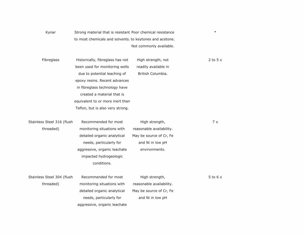
Kynar Strong material that is resistant
to most chemicals and solvents.
Poor chemical resistance
to keytones and acetone.
Not commonly available.
*
Fibreglass Historically, fibreglass has not
been used for monitoring wells
due to potential leaching of
epoxy resins. Recent advances
in fibreglass technology have
created a material that is
equivalent to or more inert than
Teflon, but is also very strong.
High strength, not
readily available in
British Columbia.
2 to 5 x
Stainless Steel 316 (flush
threaded)
Recommended for most
monitoring situations with
detailed organic analytical
needs, particularly for
aggressive, organic leachate
impacted hydrogeologic
conditions.
High strength,
reasonable availability.
May be source of Cr, Fe
and Ni in low pH
environments.
7 x
Stainless Steel 304 (flush
threaded)
Recommended for most
monitoring situations with
detailed organic analytical
needs, particularly for
aggressive, organic leachate
High strength,
reasonable availability.
May be source of Cr, Fe
and Ni in low pH
5 to 6 x
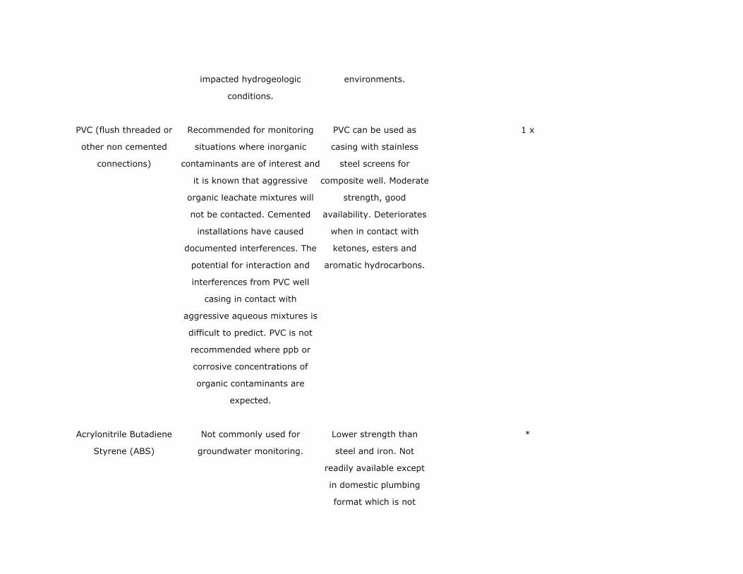
impacted hydrogeologic
conditions.
environments.
PVC (flush threaded or
other non cemented
connections)
Recommended for monitoring
situations where inorganic
contaminants are of interest and
it is known that aggressive
organic leachate mixtures will
not be contacted. Cemented
installations have caused
documented interferences. The
potential for interaction and
interferences from PVC well
casing in contact with
aggressive aqueous mixtures is
difficult to predict. PVC is not
recommended where ppb or
corrosive concentrations of
organic contaminants are
expected.
PVC can be used as
casing with stainless
steel screens for
composite well. Moderate
strength, good
availability. Deteriorates
when in contact with
ketones, esters and
aromatic hydrocarbons.
1 x
Acrylonitrile Butadiene
Styrene (ABS)
Not commonly used for
groundwater monitoring.
Lower strength than
steel and iron. Not
readily available except
in domestic plumbing
format which is not
*
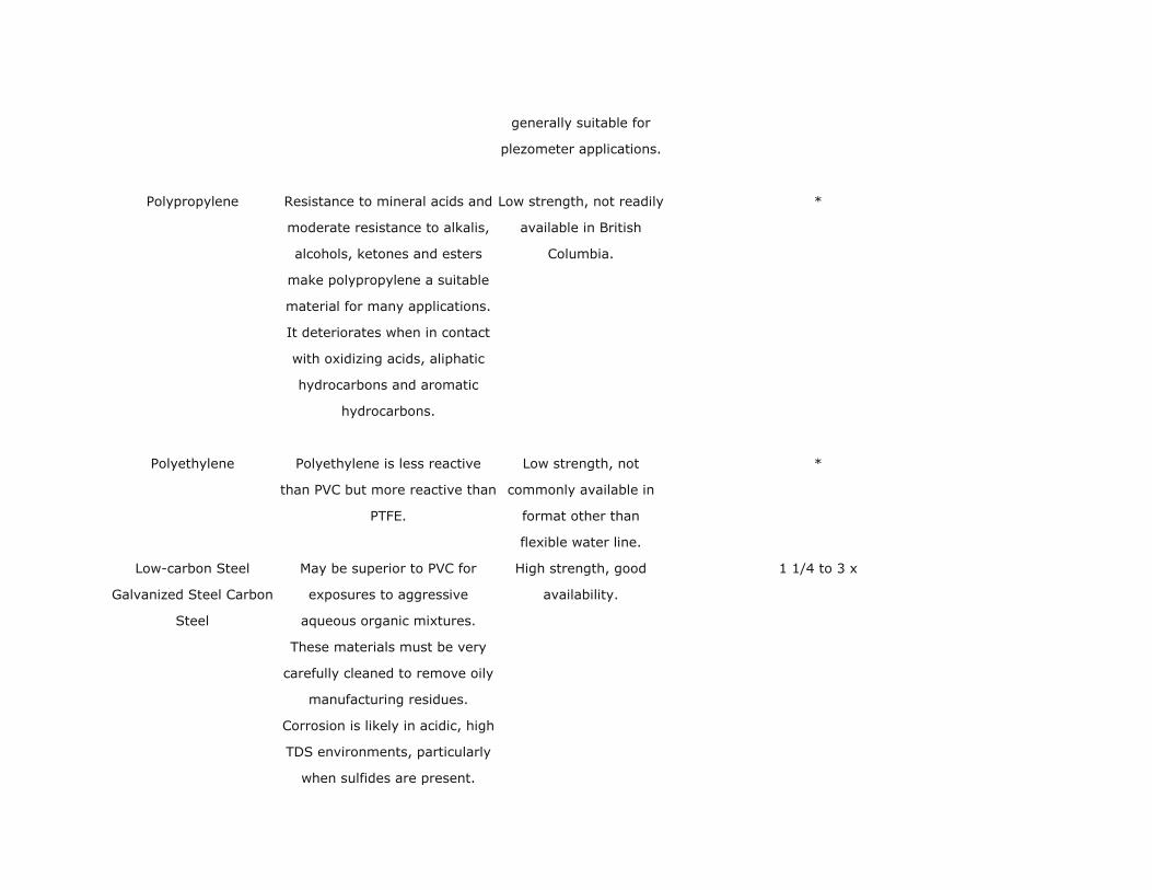
generally suitable for
plezometer applications.
Polypropylene Resistance to mineral acids and
moderate resistance to alkalis,
alcohols, ketones and esters
make polypropylene a suitable
material for many applications.
It deteriorates when in contact
with oxidizing acids, aliphatic
hydrocarbons and aromatic
hydrocarbons.
Low strength, not readily
available in British
Columbia.
*
Polyethylene Polyethylene is less reactive
than PVC but more reactive than
PTFE.
Low strength, not
commonly available in
format other than
flexible water line.
*
Low-carbon Steel
Galvanized Steel Carbon
Steel
May be superior to PVC for
exposures to aggressive
aqueous organic mixtures.
These materials must be very
carefully cleaned to remove oily
manufacturing residues.
Corrosion is likely in acidic, high
TDS environments, particularly
when sulfides are present.
High strength, good
availability.
1 1/4 to 3 x

Products of corrosion are mainly
Fe and Mn, except for
galvanized steel which may
release Zn and Cd. Weathered
steel surfaces present very
active adsorption sites for trace
organic and inorganic chemical
species.

Guidelines for Environmental Monitoring at Municipal Solid Waste Landfills
Appendix B: Drilling Methods Common to British Columbia
DRILLING METHODS
Hollow /
Solid Stem
Auger
Sonic
Drilling
Air
Rotary
Mud
Rotary
Downhole
(Becker)
Hammer
Cable
Tool
Backhoe
Excavation
Applicable Geology
Surficial Sediments X X X X X
Fine Granulated Sediments X X X
Soft Rock X
Cohesive Sediments X X X
Unconsolidated Sediments X X X
Bedrock X X
Soft to Mod. Dense Sediments X
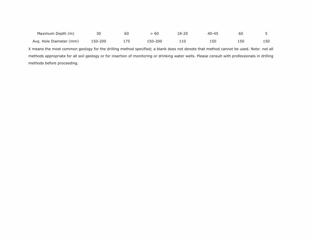
Maximum Depth (m) 30 60 > 60 18-20 40-45 60 5
Avg. Hole Diameter (mm) 150-200 175 150-200 110 150 150 150
X means the most common geology for the drilling method specified; a blank does not denote that method cannot be used. Note: not all
methods appropriate for all soil geology or for insertion of monitoring or drinking water wells. Please consult with professionals in drilling
methods before proceeding.

Guidelines for Environmental Monitoring at Municipal Solid Waste
Landfills
Appendix C: Typical Monitoring Well Design
Monitoring Well Design - Single Cased Well*
*Reprint with permission from the Annual Book of ASTM Standards, copyright
American Society for Testing and Materials, 1916 Race Street, Philadelphia, PA 19103

Monitoring Well Design - Multi-Cased Well*
*Reprint with permission from the Annual Book of ASTM Standards, copyright
American Society for Testing and Materials, 1916 Race Street, Philadelphia, PA 19103

Guidelines for Environmental Monitoring at Municipal Solid Waste Landfills
Appendix D: Sampling Equipment*
Sampling
Devices
How the Sampling
Device Operates
Pumping Rates Characteristics Disadvantages
Air Lift Pump An air lift pump collects a
water sample by bubbling a
gas at depth in the well or
tube.
Pumping rates depend on
the size of the pump being
used and how many pumps
are used for each well.
Air lift sampling can be
useful in monitoring wells
that need to be pumped
only at periodic intervals.
Air lift methods result in
considerable sample agitation
and mixing in the well.
Submersible Pump Water is transported to the
surface by centrifugal action
through an access tube.
Vary from 26.5 - 53.0 Lpm
depending upon the depth
of the pump.
A submersible pump
provides higher extraction
rates than most other
methods.
Considerable sample agitation
and the potential introduction
of trace metals into the sample
from pump materials results.
Suction Lift Pump Suction lift can be categorized
as direct line, centrifugal and
peristaltic.
Vary from 19 - 151 Lpm for
direct line method. Approx.
3.7 Lpm for peristaltic
pump method.
Suction life approaches
offer a simple retrieval
method for shallow
monitoring.
Degassing and agitation occur
as a result of suction lift.
Bladder Pump Water enters the flexible
membrane through the lower
check valve; compressed gas
The 4.4 cm pump is
capable of providing
samples (approx. 2.6 - 5.6
Bladder pumps prevent
contact between the gas
and water sample and can
The large gas volumes
required, especially at depth,
potential bladder rupture, and

is injected into the cavity
between the stainless steel
housing and the bladder.
Lpm) from depths in excess
of 76 m.
be fabricated entirely of
Teflon and stainless steel.
the difficulty in disassembling
the unit for thorough cleaning.
Gas Displacement
Pump
A column of water under
linear flow conditions is forced
to the surface without
extensive mixing of the
pressurized gas and water.
Flow rates of about 2.8
Lpm at 36.5 m are possible
with a standard 3.7 cm
inner diameter by 4.57 cm
long pump.
Gas displacement pumps
provide a reliable means for
obtaining a highly
representative groundwater
sample.
Possibility of gas water
interface, a degree of mixing,
and sample degassing can
occur during transport.
Gas Piston Pump A double piston pump utilizes
compressed air to force a
piston to raise the sample to
the surface.
Pumping rates of 0.5 Lpm
have been reported from
30.5 m; sampling depths of
152 m are possible.
The gas piston pump
provides continuous sample
withdrawal at depths
greater than is possible
with most other
approaches.
Contribution of trace elements
from the stainless steel and
brass is a potential problem.
Packer Pump The hydraulic activated
packers are wedged against
the casing wall or screen, the
sampling unit collects water
samples only from the isolated
portion of the well.
Vertical movement of water
outside the well casing
during sampling is possible
with packer pumps but
depends upon the pumping
rate and subsequent
disturbance.
A packer assembly allows
the isolation of sampling
points within a well.
Deterioration of the expandable
material will occur with time,
thereby increasing the
possibility of undesirable
organic contaminants entering
the water sample.

Inertial Lift Pump The operating principle of the
pump is based on the inertia
of a column of water
contained within a riser
tubing.
Pumping rates of between
0.05 to 10.0 Lpm have
been recorded.
The inertial pump is
inexpensive and offers
multiple uses for
groundwater monitoring
wells.
The tubing coils, though
reasonably lightweight, are stiff
and may be awkward to
transfer from well to well.
*Text extracted from Appendix D, Piteau (1990), from R.D. Morrison (1983).

Guidelines for Environmental Monitoring at Municipal Solid Waste Landfills
Appendix E: Sample Container and Preservation Criteria
Type of Analysis Size Type Preservation Hold Time
Water - Bacteriology
Coliform, fecal and / or total 250 ml P, ster 4 deg. C, do NOT freeze 48 hours
Standard plate count 250 ml P, ster 4 deg. C, do NOT freeze 48 hours
BOD 1 L P 4 deg. C, exclude all air 48 hours
BOD & TSS 2 L P 4 deg., C, exclude all air 48 hours
Chlorophyll / Phaeophytin membrane or GF / C
Filter
store frozen in dark, with dessicant N/A
Microtox 100 ml G, a 4 deg. C, exclude all air 5 days
Bioassay, Daphnia 4 L P 4 deg. C, exclude all air 5 days
Water - Inorganic Analysis Container size is determined by the type and number of analysis

General chemistry and anions 1 to 4 L P keep cool 4 deg. C 72 hours
Mercury, total 1 L or 500 ml G, L (MERCURY) 6 ML 10% K2Cr2O7+6 ml H2S04 per L 28 days
Metals, dissolved 250 ml P, L field filter & press HNO3 tp pH < 2 6 months
Metals, total 250 ml P, L (METALS) pres HNO3 to pH <2 6 months
Carbon TIC / TOC, Inorg / org 100 ml P or G 4 deg. C 72 hours
Chemical Oxygen Demand, COD 250 ml P 0.2 ml H2SO4 / 250 ml 72 hours
Cyanide, SAD and / or WAD 1 L P NaOH to pH > 12 72 hours
Oil & Grease 1 L G HCL to pH <2 28 days
Phenolics, total 1 L G, A H3PO4 to pH 4+5 ml 20% CuSO4 72 hours
Phosphorus, Low level 100 or 250 G, A, R keep cool, 4 deg. C 72 hours
Sulphide, total 500 ml P or G 1 ml 2N Zinc Acetate, exclude air 72 hours
Water - Organic Analysis

AOX (Adsorbable Organic Halides) 500 ml G, A, R, B pH to <2 with HNO3 30 days
Chlorophenols PCP, TTCP, TCP 1 L G, A, Solv 4 deg. C 30 days
Dioxins / Furans 3 x 1 L G, A, Solv 4 deg. C 30 days
EPA 624, Volatiles or BTEX 3 x 40 ml vial, G, B, P & T headspace-free, 4 deg. C (Na2S203 if
chlorinated)
14 days
EPA 625, CP / OC / PAH / PCB 1 L G, A, Solv 4 deg. C 30 days
AEH, TCMTB 1 L / analysis G, A, Solv 4 deg. C 30 days
Hydrocarbons 500 ml G, A, Solv 4 deg. C 30 days
Copper quinolate (copper 8, PQ-8) 250, 500 ml 4 deg. C, HCL to pH <2 30 days
Resin Acids 1 L G, A, Solv 4 deg. C, NaOH to pH 12 21 days
Trihalomethanes 500 ml G, A, Solv Na2S203, headspace-free, 4 deg. C 14 days
IPBC / DDAC 1 L P or G 4 deg. C, 6N HCL, 2 ml/L 14 days
Soils, Sediments, Tissues and Others
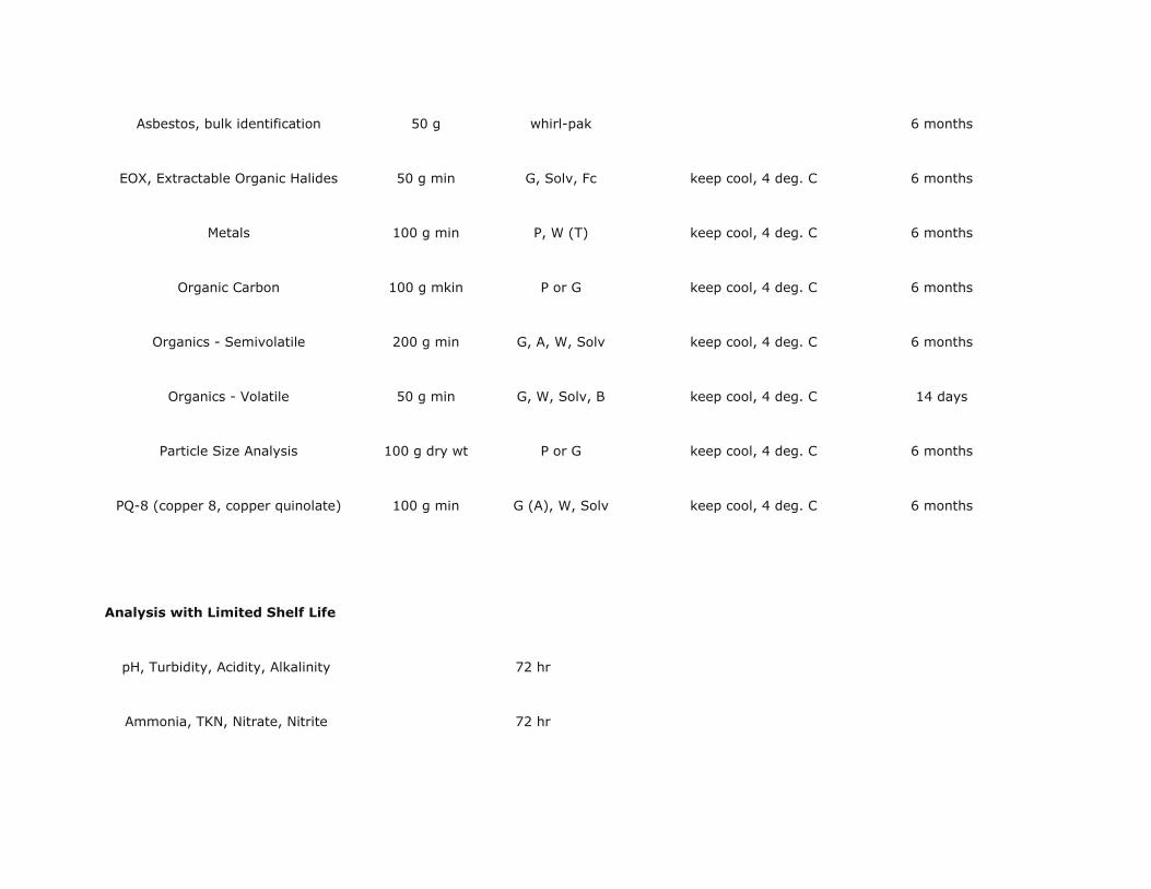
Asbestos, bulk identification 50 g whirl-pak 6 months
EOX, Extractable Organic Halides 50 g min G, Solv, Fc keep cool, 4 deg. C 6 months
Metals 100 g min P, W (T) keep cool, 4 deg. C 6 months
Organic Carbon 100 g mkin P or G keep cool, 4 deg. C 6 months
Organics - Semivolatile 200 g min G, A, W, Solv keep cool, 4 deg. C 6 months
Organics - Volatile 50 g min G, W, Solv, B keep cool, 4 deg. C 14 days
Particle Size Analysis 100 g dry wt P or G keep cool, 4 deg. C 6 months
PQ-8 (copper 8, copper quinolate) 100 g min G (A), W, Solv keep cool, 4 deg. C 6 months
Analysis with Limited Shelf Life
pH, Turbidity, Acidity, Alkalinity 72 hr
Ammonia, TKN, Nitrate, Nitrite 72 hr

P ortho, total, total dissolved 72 hr
Specific Conductance 72 hr
Legend
P = plastic Ster = sterilized B = baked
G = glass Solv = solvent cleaned T = tissue cup
A = amber Fc = foil lined cap
W = wide mouth R = acid rinsed
L () = labelled (description)
P & T = purge and trap vials

Guidelines for Environmental Monitoring at Municipal Solid Waste
Landfills
Appendix F: Generalized Flow Diagram of Groundwater Sampling Steps

*Denotes samples which should be filtered in order to determine dissolved constituents. Filtration
should be accomplished preferably with in-line filters and pump pressure or by N2 pressure methods.
Samples for dissolved gases or volatile organics should not be filtered. In instances where well
development procedures do not allow for turbidity-free samples and may bias analytical results, split
samples should be spiked with standards before filtration.
Both spiked samples and regular samples should be analyzed to determine recoveries from both types
of handling.
**Denotes analytical determinations which should be made in the field.
(Modified Piteau 1990, Fig. 5.7)


