
Refresh Your Memory, Inc. | 6920 Santa Teresa Blvd Suite 201 | San Jose, CA 95119 408.224.9167 | www.factorywiz.com
CNC Configuration Sheet
Fanuc 15M
CNC Parameters: You will need to verify all parameters listed below that correspond to your CNC control. These parameters may not match your particular machine’s control. Document (Phone camera) original settings before making modifications! Setting screen: Punch code- 1=ISO TV CHECK=0 OFF Under Service page: 0000 = xxx01000 (ISO) 0020 = 1 (Input device Foreground) 0021 = 1 (Output device Foreground) 0022 = 1 (Input device Background) 0023 = 1 (Output device Background) 5001 to 1 (Device Select) 5002 to 2 (RS232 Device Select) 5110 to 3 (Device type DC Codes used) 5111 to 1 (1 stop bit) 5112 to 10 (4800 baud) 11=9600, 9=2400, 8=1200 7=600 6=300 FactoryWiz DNC Settings: Basic Communication 1.01- Port Type: Standard 1.11- Baud: 4800 1.12- Data Bits: 7 1.13- ASCII Even 1.14- Stop Bits: 1 1.15- Handshake: XON/XOFF Sending Options 2.11- Leader: %<10> 2.12- Trailer: % 2.23- Skip lines that contain: % 2.31- Automatic timeout: 7 Receiving Options 3.11- Program identifier 1: O 3.12- Program Identifier 2: : 3.21- Receive timeout: 3 3.31- Ignore data before first end-of-block: True 3.32- Ignore data after last end-of-block: True Remote Commands 4.02- Request for file command: GET-
DNC Systems
Refresh Your Memory, Inc. | 6920 Santa Teresa Blvd Suite 201 | San Jose, CA 95119 408.224.9167 | www.factorywiz.com
4.03- Request for file command (drip feed): DNC- 4:11- Request to save command: PUT-
Additional Notes: Changing CNC Parameters: System (Param) screen: To set parameters, move dial to MDI mode on machine. Press SETTINGS key. Change PWE (#8000) to 1. The CNC will alarm. Outputting CNC Programs: To output a program, set the CNC to "edit" mode. Press the PROG key on the control panel. Use the right arrow (Page) key until PUNCH appears. Press PUNCH, then Press THIS. Inputting CNC Programs: To input a program, set the CNC to "edit" mode. Press the PROG key on the control panel. Use the right arrow(Page)keys until READ appears. Press READ, then press ALL.
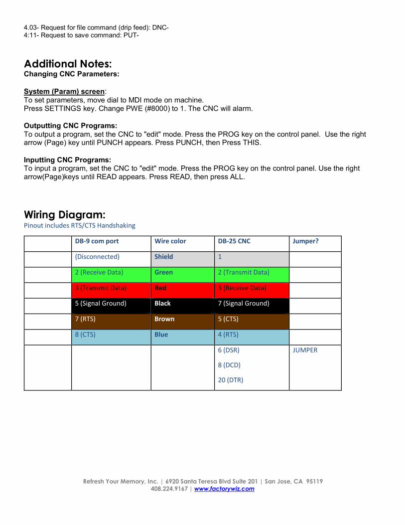
Wiring Diagram: Pinout includes RTS/CTS Handshaking
DB-9 com port Wire color DB-25 CNC Jumper?
(Disconnected) Shield 1
2 (Receive Data) Green 2 (Transmit Data)
3 (Transmit Data) Red 3 (Receive Data)
5 (Signal Ground) Black 7 (Signal Ground)
7 (RTS) Brown 5 (CTS)
8 (CTS) Blue 4 (RTS)
6 (DSR)
8 (DCD)
20 (DTR)
JUMPER

Refresh Your Memory, Inc. | 6920 Santa Teresa Blvd Suite 201 | San Jose, CA 95119 408.224.9167 | www.factorywiz.com


