basic system management configuration guide, cisco … · basic system management configuration...
TRANSCRIPT

Basic System Management ConfigurationGuide, Cisco IOS Release 15M&T
Americas HeadquartersCisco Systems, Inc.170 West Tasman DriveSan Jose, CA 95134-1706USAhttp://www.cisco.comTel: 408 526-4000 800 553-NETS (6387)Fax: 408 527-0883

THE SPECIFICATIONS AND INFORMATION REGARDING THE PRODUCTS IN THIS MANUAL ARE SUBJECT TO CHANGE WITHOUT NOTICE. ALL STATEMENTS,INFORMATION, AND RECOMMENDATIONS IN THIS MANUAL ARE BELIEVED TO BE ACCURATE BUT ARE PRESENTED WITHOUT WARRANTY OF ANY KIND,EXPRESS OR IMPLIED. USERS MUST TAKE FULL RESPONSIBILITY FOR THEIR APPLICATION OF ANY PRODUCTS.
THE SOFTWARE LICENSE AND LIMITED WARRANTY FOR THE ACCOMPANYING PRODUCT ARE SET FORTH IN THE INFORMATION PACKET THAT SHIPPEDWITH THE PRODUCT AND ARE INCORPORATED HEREIN BY THIS REFERENCE. IF YOU ARE UNABLE TO LOCATE THE SOFTWARE LICENSE OR LIMITEDWARRANTY, CONTACT YOUR CISCO REPRESENTATIVE FOR A COPY.
The Cisco implementation of TCP header compression is an adaptation of a program developed by the University of California, Berkeley (UCB) as part of UCB’s public domain versionof the UNIX operating system. All rights reserved. Copyright © 1981, Regents of the University of California.
NOTWITHSTANDING ANY OTHER WARRANTY HEREIN, ALL DOCUMENT FILES AND SOFTWARE OF THESE SUPPLIERS ARE PROVIDED “AS IS” WITH ALLFAULTS. CISCO AND THE ABOVE-NAMED SUPPLIERS DISCLAIM ALL WARRANTIES, EXPRESSED OR IMPLIED, INCLUDING, WITHOUT LIMITATION, THOSE OFMERCHANTABILITY, FITNESS FOR A PARTICULAR PURPOSE AND NONINFRINGEMENT OR ARISING FROM A COURSE OF DEALING, USAGE, OR TRADEPRACTICE.
IN NO EVENT SHALL CISCO OR ITS SUPPLIERS BE LIABLE FOR ANY INDIRECT, SPECIAL, CONSEQUENTIAL, OR INCIDENTAL DAMAGES, INCLUDING,WITHOUT LIMITATION, LOST PROFITS OR LOSS OR DAMAGE TO DATA ARISING OUT OF THE USE OR INABILITY TO USE THIS MANUAL, EVEN IF CISCO ORITS SUPPLIERS HAVE BEEN ADVISED OF THE POSSIBILITY OF SUCH DAMAGES.
Cisco and the Cisco logo are trademarks or registered trademarks of Cisco and/or its affiliates in the U.S. and other countries. To view a list of Cisco trademarks, go to this URL: www.cisco.com/go/trademarks. Third-party trademarks mentioned are the property of their respective owners. The use of the word partner does not imply a partnership relationshipbetween Cisco and any other company. (1110R)
Any Internet Protocol (IP) addresses and phone numbers used in this document are not intended to be actual addresses and phone numbers. Any examples, command display output,network topology diagrams, and other figures included in the document are shown for illustrative purposes only. Any use of actual IP addresses or phone numbers in illustrative contentis unintentional and coincidental.
© 2013 Cisco Systems, Inc. All rights reserved.

C O N T E N T S
Performing Basic System Management 1
Finding Feature Information 1
Information About Performing Basic System Management 1
System Name 2
Command Aliases 2
Minor Services 2
BOOTP Server 3
Finger Protocol 3
Hidden Telnet Addresses 3
EXEC Startup Delay 3
Idle Telnet Connections 3
Interval for Load Data 4
Number of TCP Transactions 4
Switching and Scheduling Priorities 4
System Buffer Size 4
How to Perform Basic System Management 5
Setting Basic System Parameters 5
Configuration Examples for Performing Basic System Management 11
Additional References 11
Feature Information for Performing Basic System Management 12
NTPv4 in IPv6 15
Finding Feature Information 15
Information About NTPv4 in IPv6 15
NTP Version 4 15
NTPv4 Overview 16
NTPv4 Features 16
IPv6 Multicast Mode 16
NTP Access Groups versus Symmetric Key Authentication 17
DNS Support for IPv6 in NTPv4 17
Basic System Management Configuration Guide, Cisco IOS Release 15M&T iii

How to Configure NTPv4 in IPv6 17
Configuring Poll-Based NTPv4 Associations 17
Configuring Symmetric Active Mode 18
Configuring Client Mode 19
Configuring Multicast-Based NTPv4 Associations 19
Configuring an Interface to Send NTPv4 Multicast Packets 20
Configuring an Interface to Receive NTPv4 Multicast Packets 20
Defining an NTPv4 Access Group 21
Configuring NTPv4 Authentication 22
Disabling NTPv4 Services on a Specific Interface 23
Configuring the Source IPv6 Address for NTPv4 Packets 24
Configuring the System as an Authoritative NTP Server 25
Updating the Hardware Clock 26
Resetting the Drift Value in the Persistent Data File 26
Troubleshooting NTPv4 in IPv6 27
Configuration Examples for NTPv4 in IPv6 28
Example: Defining an NTPv4 Access Group 28
Additional References 28
Feature Information for NTPv4 in IPv6 29
Network Time Protocol 31
Finding Feature Information 31
Information About Network Time Protocol 31
Time and Calendar Services 31
Network Time Protocol 32
Poll-Based NTP Associations 33
Broadcast-Based NTP Associations 34
NTP Access Group 34
NTP Services on a Specific Interface 35
Source IP Address for NTP Packets 35
System as an Authoritative NTP Server 36
Orphan Mode 36
Prerequisites for Orphan Mode 37
Simple Network Time Protocol 37
VINES Time Service 37
Hardware Clock 38
Contents
Basic System Management Configuration Guide, Cisco IOS Release 15M&Tiv
Time Ranges 38
How to Configure Network Time Protocol 39
Configuring NTP 39
Restrictions for Network Time Protocol 39
Configuring Poll-Based NTP Associations 40
Configuring Broadcast-Based NTP Associations 41
Configuring NTP Authentication 42
Configuring an External Reference Clock 44
Configuring Orphan Mode 46
Configuring SNTP 47
Configuring VINES Time Service 48
Configuring the Time and Date 49
Setting the Hardware Clock 51
Configuring Time Ranges 54
Verifying Network Time Protocol 55
Configuration Examples for Network Time Protocol 57
Example: Configuring Network Time Protocol 57
Additional References for Network Time Protocol 57
Feature Information for Network Time Protocol 58
Configuring System Logging Counts 61
Feature Overview 61
Benefits 61
Related Features and Technologies 62
Finding Feature Information 62
Supported Standards MIBs and RFCs 62
Configuration Tasks 62
Enabling the Error Log Count Capability 62
Verifying the Error Log Count Capability 63
Configuration Examples 63
Enabling the Error Log Count Capability Example 63
Feature Information for Event Tracer 63
CPU Thresholding Notification 65
Finding Feature Information 65
Restrictions for CPU Thresholding Notification 65
Information About CPU Thresholding Notification 65
Contents
Basic System Management Configuration Guide, Cisco IOS Release 15M&T v

Rising Threshold 66
Falling Threshold 66
How to Configure CPU Thresholding Notification 66
Enabling CPU Thresholding Notification 66
Defining CPU Thresholding Notification 67
Setting the Entry Limit and Size of CPU Utilization Statistics 68
Configuration Examples for CPU Thresholding Notification 69
Setting a Rising CPU Thresholding Notification Example 69
Setting a Falling CPU Thresholding Notification Example 69
Additional References 69
Feature Information for CPU Thresholding Notification 70
DSP Operational State Notifications 73
Finding Feature Information 73
Prerequisites for DSP Operational State Notifications 73
Information About DSP Operational State Notifications 73
CISCO-DSP-MGMT-MIB 74
DSP Operational State Notification 74
Benefits of DSP Operational State Notifications 74
How to Enable DSP Operational State Notifications 74
Enabling DSP Operational State Notifications from the CLI 74
Enabling DSP Operational State Notifications Using an SNMP Application 75
Configuration Examples for DSP Operational State Notifications 76
Enabling DSP Operational State Notifications Using the CLI Example 76
Enabling DSP Operational State Notifications Using an SNMP Application Example 76
Additional References 76
Feature Information for DSP Operational State Notifications 77
Configuring the Event Tracer 79
Feature Overview 79
Benefits 80
Restrictions 80
Finding Feature Information 80
Supported Standards MIBs and RFCs 80
Prerequisites 82
Configuration Tasks 82
Configuring Event Tracing 83
Contents
Basic System Management Configuration Guide, Cisco IOS Release 15M&Tvi

Configuring the Event Trace Size 83
Configuring the Event Trace Message File 83
Verifying Event Trace Operation 83
Troubleshooting Tips 85
Configuration Examples 86
Configuring Event Tracing for One Component Example 86
Configuring Event Tracing for Multiple Components Example 86
Configuring the Event Trace Size Example 86
Configuring the Event Trace Message File Example 86
Feature Information for Event Tracer 86
Memory Threshold Notifications 89
Finding Feature Information 89
Information About Memory Threshold Notifications 89
Memory Threshold Notifications 89
Memory Reservation 90
How to Define Memory Threshold Notifications 90
Setting a Low Free Memory Threshold 90
Reserving Memory for Critical Notifications 91
Configuration Examples for Memory Threshold Notifications 92
Setting a Low Free Memory Threshold Examples 92
Reserving Memory for Critical Notifications Example 93
Additional References 93
Feature Information for Memory Threshold Notifications 94
NTPv4 MIB 97
Finding Feature Information 97
Information About the NTPv4 MIB 97
NTPv4 MIB 97
How to Verify the NTPv4 MIB 98
Verifying NTPv4 MIB 98
Configuration Examples for Verifying NTPv4 MIB 99
Example: Verifying the NTP4 MIB 99
Additional References 100
Feature Information for the NTPv4 MIB 101
Troubleshooting and Fault Management 103
Finding Feature Information 103
Contents
Basic System Management Configuration Guide, Cisco IOS Release 15M&T vii

Troubleshooting and Fault Management Task List 103
Displaying System Information Using show Commands 104
Testing Network Connectivity 106
Configuring the TCP Keepalive Packet Service 106
Testing Connections with the ping Command 106
Tracing Packet Routes 106
Logging System Messages 107
Enabling System Message Logging 107
Enabling Message Logging for a Slave Card 108
Setting the Syslog Destination 108
Configuring Synchronization of Logging Messages 108
Enabling Time-Stamps on Log Messages 109
Limiting the Error Message Severity Level and Facilities 109
Defining the UNIX System Logging Facility 111
Displaying Logging Information 112
Logging Errors to a UNIX Syslog Daemon 112
Setting the Syslog Source Address 112
Using Field Diagnostics on Line Cards 113
Troubleshooting Specific Line Cards 114
Storing Line Card Crash Information 114
Creating Core Dumps for System Exceptions 114
Specifying the Destination for the Core Dump File 115
Using TFTP for Core Dumps 115
Using FTP for Core Dumps 116
Using rcp for Core Dumps 117
Using a Flash Disk for Core Dumps 118
Creating an Exception Memory Core Dump 118
Setting a Spurious Interrupt Core Dump 119
Enabling Debug Operations 120
Enabling Conditionally Triggered Debugging 121
Enabling Protocol-Specific debug Commands 122
Enabling Conditional Debugging Commands 122
Displaying Messages for One Interface 122
Displaying Messages for Multiple Interfaces 123
Limiting the Number of Messages Based on Conditions 123
Contents
Basic System Management Configuration Guide, Cisco IOS Release 15M&Tviii

Specifying Multiple Debugging Conditions 124
Conditionally Triggered Debugging Configuration Examples 124
Using the Environmental Monitor 125
Configuring the XML Interface to Syslog Messages 127
Finding Feature Information 127
Information About the XML Interface to Syslog Messages Feature 127
Cisco IOS System Message Logging 127
XML-Formatted System Message Logging 128
System Logging Message Formatting 128
How to Configure XML Formatting of Syslog Messages 131
Configuration Examples for XML Formatting of Syslog Messages 132
Additional References 133
Feature Information for XML Interface to Syslog Messages 134
Glossary 135
Network Time Protocol 137
Finding Feature Information 137
Restrictions for Network Time Protocol 137
Information About Network Time Protocol 138
Simple Network Time Protocol 138
How to Configure Network Time Protocol 139
Configuring NTP 139
Configuring NTP Authentication 139
Verifying Network Time Protocol 140
Troubleshooting Simple Network Time Protocol 142
Configuration Examples for Network Time Protocol 143
Example: Configuring Network Time Protocol 143
Additional References for Network Time Protocol 143
Feature Information for Network Time Protocol 144
Contents
Basic System Management Configuration Guide, Cisco IOS Release 15M&T ix

Contents
Basic System Management Configuration Guide, Cisco IOS Release 15M&Tx

Performing Basic System Management
This module describes the basic tasks that you can perform to manage the general system features of theCisco IOS software--those features that are generally not specific to a particular protocol.
• Finding Feature Information, page 1• Information About Performing Basic System Management, page 1• How to Perform Basic System Management, page 5• Configuration Examples for Performing Basic System Management, page 11• Additional References, page 11• Feature Information for Performing Basic System Management, page 12
Finding Feature InformationYour software release may not support all the features documented in this module. For the latest caveatsand feature information, see Bug Search Tool and the release notes for your platform and software release.To find information about the features documented in this module, and to see a list of the releases in whicheach feature is supported, see the feature information table at the end of this module.
Use Cisco Feature Navigator to find information about platform support and Cisco software image support.To access Cisco Feature Navigator, go to www.cisco.com/go/cfn. An account on Cisco.com is not required.
Information About Performing Basic System Management• System Name, page 2• Command Aliases, page 2• Minor Services, page 2• Hidden Telnet Addresses, page 3• EXEC Startup Delay, page 3• Idle Telnet Connections, page 3• Interval for Load Data, page 4• Number of TCP Transactions, page 4• Switching and Scheduling Priorities, page 4• System Buffer Size, page 4
Basic System Management Configuration Guide, Cisco IOS Release 15M&T 1

System NameThe system name, also called the hostname, is used to uniquely identify the system in your network. Thesystem name is displayed at the CLI prompt. If no name is configured, the system default name is Router.
Command AliasesCommand aliases allow you to configure alternative syntax for commands. You may want to create aliasesfor commonly used or complex commands. For example, you could assign the alias save config to the copyrunning-config startup-config command to reduce the amount of typing you have to perform, or if yourusers might find the save config command easier to remember. Use word substitutions or abbreviations totailor the command syntax for you and your user community.
Remember that any aliases you configure will be effective only on your system, and that the originalcommand syntax will appear in the configuration file.
Minor ServicesMinor services are small servers that run on your routing device and are useful for basic system testing andfor providing basic network functions. Minor services are useful for testing connections from another hoston the network.
Cisco small servers are conceptually equivalent to daemons.
Small servers provided by Cisco IOS software-based devices include TCP, UDP, HTTP, BootstrapProtocol (BOOTP), and Finger. For information about the HTTP server, see the “Using the Cisco WebBrowser User Interface” chapter in the Cisco IOS Configuration Fundamentals Configuration Guide.
The TCP small server provides the following minor services:
• Chargen--Generates a stream of ASCII data. To test this service, issue the telnet a.b.c.dchargencommand from a remote host.
• Daytime--Returns the system date and time if you have configured Network Time Protocol (NTP) orset the date and time manually. To test this service, issue the telnet a.b.c.d daytimecommand from aremote host.
• Discard--Discards whatever you type. To test this service, issue the telnet a.b.c.d discardcommandfrom a remote host.
• Echo--Echoes back whatever you type. To test this service, issue the telnet a.b.c.d echocommandfrom a remote host.
The UDP small server provides the following minor services:
• Chargen--Discards the datagram that you send and responds with a 72-character string of ASCIIcharacters terminated with a CR+LF (carriage return and line feed).
• Discard--Discards the datagram you send.• Echo--Echoes the payload of the datagram that you send.
Minor services are disabled by default.
System Name Information About Performing Basic System Management
Basic System Management Configuration Guide, Cisco IOS Release 15M&T2

Caution Enabling minor services creates the potential for certain types of denial-of-service (DoS) attacks, such asthe UDP diagnostic port attack. Therefore, any network device that has UDP, TCP, BOOTP, or Fingerservices should be protected by a firewall or have the minor services disabled. For information onpreventing UDP diagnostic port attacks, see the white paper titled Defining Strategies to Protect AgainstUDP Diagnostic Port Denial of Service Attacks a vailable on Cisco.com.
• BOOTP Server, page 3• Finger Protocol, page 3
BOOTP ServerYou can enable or disable an async line Bootstrap Protocol (BOOTP) service on your routing device. Thissmall server is enabled by default. Due to security considerations, this service should be disabled if you arenot using it.
Because DHCP is based on the BOOTP, both of these service share the well-known UDP server port 67(per the Internet standards and RFCs). For more information about DHCP configuration in the Cisco IOSsoftware, see the Cisco IOS IP Addressing Configuration Guide. For more information about BOOTP, seeRFC 951. Interoperation between BOOTP and DHCP is defined in RFC 1534. DHCP is defined in RFC2131.
Finger ProtocolThe Finger protocol allows users throughout the network to get a list of the users currently using aparticular routing device. The information displayed includes the processes running on the system, the linenumber, connection name, idle time, and terminal location. This information is provided through the CiscoIOS software show users EXEC command.
Hidden Telnet AddressesYou can hide addresses while attempting to establish a Telnet session. The hide feature suppresses thedisplay of the address and continues to display all other messages that normally would be displayed duringa connection attempt, such as detailed error messages if the connection fails.
EXEC Startup DelayTo delay the startup of the EXEC process on noisy lines until the line has been idle for 3 seconds, use theservice exec-wait command in global configuration mode.
This command is useful on noisy modem lines or when a modem attached to the line is configured toignore Microcom Networking Protocol (MNP) or V.42 negotiations, and when MNP or V.42 modems aredialing in. In these cases, noise or MNP/V.42 packets might be interpreted as usernames and passwords,causing authentication failure before the user can type a username or password. This command is not usefulon nonmodem lines or lines without some kind of login configured.
Idle Telnet ConnectionsNormally, data sent to noncurrent Telnet connections is accepted and discarded. When the service telnet-zero-idle command is enabled and a session is suspended (that is, some other connection is made active),
Hidden Telnet AddressesBOOTP Server
Basic System Management Configuration Guide, Cisco IOS Release 15M&T 3

the TCP window is set to zero. This action prevents the remote host from sending any more data until theconnection is resumed. Use this command when all messages sent by the host must be seen by the usersand the users are likely to use multiple sessions. Do not use this command if your host will eventually timeout and log out a TCP user whose window is zero.
Interval for Load DataYou can change the period of time over which a set of data is used for computing load statistics. Decisions,such as dial backup, depend on these statistics. If you decrease the load interval, the average statistics arecomputed over a shorter period of time and are more responsive to bursts of traffic.
Number of TCP TransactionsWhen you are using a standard TCP implementation to send keystrokes between machines, TCP tends tosend one packet for each keystroke typed, which can use up the bandwidth and contribute to the congestionon larger networks.
John Nagle’s algorithm (RFC 896) helps alleviate the small-packet problem in TCP. The first charactertyped after the connection establishment is sent in a single packet, but TCP holds any additional charactersthat are typed until the receiver acknowledges the previous packet. Then the second, larger packet is sent,and the additional typed characters are saved until the acknowledgment comes back. The effect is toaccumulate characters into larger chunks, and pace their transmission to the network at a rate matching theround-trip time of the given connection. This method is usually preferable for all TCP-based traffic.
By default, the Nagle algorithm is not enabled.
Switching and Scheduling PrioritiesThe normal operation of the network server allows the switching operations to use as much of the centralprocessor as required. If the network is running unusually heavy loads that do not allow the processor thetime to handle the routing protocols, you may need to give priority to the system process scheduler.
System Buffer SizeYou can adjust the initial buffer pool settings and limits at which temporary buffers are created anddestroyed.
During normal system operation, there are two sets of buffer pools: public and interface. They behave asfollows:
• The buffers in the public pools grow and shrink based upon demand. Some public pools are temporaryand are created and destroyed as needed. Other public pools are permanently allocated and cannot bedestroyed. Public buffer pools are labeled as small, middle, big, very big, large, and huge.
• Interface pools are static--that is, they are all permanent. One interface pool exists for each interface.For example, a Cisco 4000 1E 4T configuration has one Ethernet buffer pool and four serial bufferpools.
The server has one pool of queueing elements and six public pools of packet buffers of different sizes. Foreach pool, the server keeps count of the number of outstanding buffers, the number of buffers in the freelist, and the maximum number of buffers allowed in the free list.
Interval for Load Data Finger Protocol
Basic System Management Configuration Guide, Cisco IOS Release 15M&T4

How to Perform Basic System Management• Setting Basic System Parameters, page 5
Setting Basic System ParametersTo set basic system parameters perform the following steps. You can perform these steps based on thecustomization requirements of your system.
SUMMARY STEPS
1. hostname name
2. prompt string
3. alias mode alias-name alias-command-line
4. service tcp-small-servers
5. service udp-small-servers
6. no ip bootp server
7. ip finger
8. ip finger rfc-compliant
9. service hide-telnet-address
10. line line-number
11. exit
12. busy-message hostname message
13. service exec-wait
14. service telnet-zero-idle
15. load-interval seconds
16. service nagle
17. scheduler interval milliseconds
18. scheduler allocate [network-microseconds process-microseconds]
19. scheduler process-watchdog {hang | normal | reload | terminate}
20. buffers {small | middle | big | verybig | large | huge | type number} {permanent | max-free | min-free| initial} number
21. exit
22. show aliases [mode]
23. show buffers
DETAILED STEPS
Step 1 hostname nameUse the hostname name command to perform the basic system management task of assigning a name for your device.
Setting Basic System ParametersHow to Perform Basic System Management
Basic System Management Configuration Guide, Cisco IOS Release 15M&T 5

Example:
Router(config)# hostname host1
Step 2 prompt stringor
no service prompt config
By default, the CLI prompt consists of the system name followed by an angle bracket (>) for user EXEC mode or apound sign (#) for privileged EXEC mode. Use the the prompt string or the no service prompt config command tocustomize the CLI prompt for your system.
Example:
Router(config)# prompt Router123
or
Example:
Router(config)# no service prompt config
Step 3 alias mode alias-name alias-command-lineUse the alias mode alias-name alias-command-line command to create a command alias.
Example:
Router(config)# alias exec save config copy running-config startup-config
Step 4 service tcp-small-serversUse the service tcp-small-servers command to enable minor TCP services such as chargen, daytime, discard, andecho.
Note The no form of the service tcp-small-servers command will appear in the configuration file when these basicservices are disabled.
Example:
Router(config)# service tcp-small-servers
Step 5 service udp-small-serversUse the service udp-small-servers command to enable minor UDP services such as chargen, daytime, discard, andecho.
Note The no form of the service udp-small-servers command will appear in the configuration file when these basicservices are disabled.
Example:
Router(config)# service udp-small-servers
Step 6 no ip bootp serverUse the no ip bootp server command to disable the BOOTP server on your platform.
Performing Basic System Management How to Perform Basic System Management
Basic System Management Configuration Guide, Cisco IOS Release 15M&T6

Example:
Router(config)# no ip bootp server
Step 7 ip fingerUse the ip finger command to enable a Cisco device to respond to Finger (port 79) requests. When the ip fingercommand is configured, the router will respond to a telnet a.b.c.d finger command from a remote host byimmediately displaying the output of the show userscommand and then closing the connection.
Example:
Router(config)# ip finger
Step 8 ip finger rfc-compliantUse the ip finger rfc-compliant command to configure the finger protocol to be compliant with RFC 1288. The ipfinger rfc-compliant command should not be configured for devices with more than 20 simultaneous users. When theip finger rfc-compliantcommand is configured, the router will wait for input before displaying any information. Theremote user can then press the Return key to display the output of the show users command, or enter /W to displaythe output of the show users wide command. After this information is displayed, the connection is closed.
Example:
Router(config)# ip finger rfc-compliant
Step 9 service hide-telnet-addressUse the service hide-telnet-address command to configure the router to suppress Telnet addresses.
Example:
Router(config)# service hide-telnet-address
Step 10 line line-numberUse the line command to enter line configuration mode.
Example:
Router(config)# line 1
Step 11 exitUse the exit command to exit line configuration mode and return to global configuration mode.
Example:
Router(config-line)# exit
Step 12 busy-message hostname messageUse the busy-message command with the service hide-telnet-addresscommand to customize the informationdisplayed during Telnet connection attempts. If the connection attempt fails, the router suppresses the address anddisplays the message specified with the busy-message command.
Performing Basic System ManagementHow to Perform Basic System Management
Basic System Management Configuration Guide, Cisco IOS Release 15M&T 7

Example:
Router(config-line)# busy-message host1 message1
Step 13 service exec-waitUse the service exec-waitcommand to delay the startup of the EXEC process on noisy lines until the line has beenidle for 3 seconds.
Example:
Router(config)# service exec-wait
Step 14 service telnet-zero-idleUse the service telnet-zero-idle command to configure the Cisco IOS software to set the TCP window to zero (0)when the Telnet connection is idle.
Example:
Router(config)# service telnet-zero-idle
Step 15 load-interval secondsUse the load-interval seconds command to change the length of time for which a set of data is used to compute loadstatistics.
Example:
Router(config)# load-interval 100
Step 16 service nagleUse the service nagle command to enable the Nagle algorithm and thereby reduce the number of TCP transactions.
Example:
Router(config)# load-interval 100
Step 17 scheduler interval millisecondsUse the scheduler interval milliseconds command to define the maximum amount of time that can elapse withoutrunning the lowest-priority system processes.
Example:
Router(config)# scheduler interval 100
Step 18 scheduler allocate [network-microseconds process-microseconds]Use the scheduler allocate command to change the amount of time that the CPU spends on fast-switching andprocess-level operations on the Cisco 7200 series and Cisco 7500 series routers.
Caution Cisco recommends that you do not change the default values of the scheduler allocate command.
Performing Basic System Management How to Perform Basic System Management
Basic System Management Configuration Guide, Cisco IOS Release 15M&T8
Example:
Router(config)# scheduler allocate 5000 200
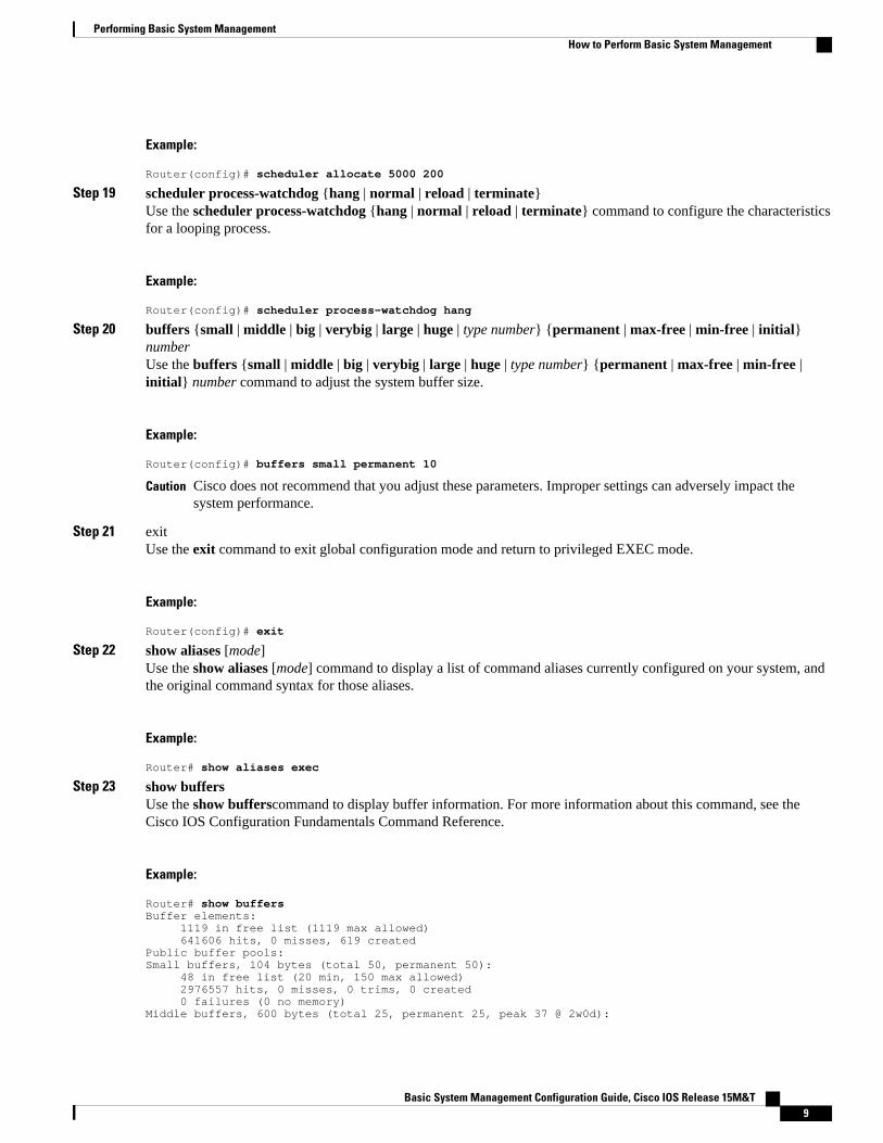
Step 19 scheduler process-watchdog {hang | normal | reload | terminate}Use the scheduler process-watchdog {hang | normal | reload | terminate} command to configure the characteristicsfor a looping process.
Example:
Router(config)# scheduler process-watchdog hang
Step 20 buffers {small | middle | big | verybig | large | huge | type number} {permanent | max-free | min-free | initial}numberUse the buffers {small | middle | big | verybig | large | huge | type number} {permanent | max-free | min-free |initial} number command to adjust the system buffer size.
Example:
Router(config)# buffers small permanent 10
Caution Cisco does not recommend that you adjust these parameters. Improper settings can adversely impact thesystem performance.
Step 21 exitUse the exit command to exit global configuration mode and return to privileged EXEC mode.
Example:
Router(config)# exit
Step 22 show aliases [mode]Use the show aliases [mode] command to display a list of command aliases currently configured on your system, andthe original command syntax for those aliases.
Example:
Router# show aliases exec
Step 23 show buffers Use the show bufferscommand to display buffer information. For more information about this command, see theCisco IOS Configuration Fundamentals Command Reference.
Example:
Router# show buffersBuffer elements: 1119 in free list (1119 max allowed) 641606 hits, 0 misses, 619 createdPublic buffer pools:Small buffers, 104 bytes (total 50, permanent 50): 48 in free list (20 min, 150 max allowed) 2976557 hits, 0 misses, 0 trims, 0 created 0 failures (0 no memory)Middle buffers, 600 bytes (total 25, permanent 25, peak 37 @ 2w0d):
Performing Basic System ManagementHow to Perform Basic System Management
Basic System Management Configuration Guide, Cisco IOS Release 15M&T 9

25 in free list (10 min, 150 max allowed) 445110 hits, 4 misses, 12 trims, 12 created 0 failures (0 no memory)Big buffers, 1536 bytes (total 50, permanent 50): 50 in free list (5 min, 150 max allowed) 58004 hits, 0 misses, 0 trims, 0 created 0 failures (0 no memory)VeryBig buffers, 4520 bytes (total 10, permanent 10): 10 in free list (0 min, 100 max allowed) 0 hits, 0 misses, 0 trims, 0 created 0 failures (0 no memory)Large buffers, 5024 bytes (total 0, permanent 0): 0 in free list (0 min, 10 max allowed) 0 hits, 0 misses, 0 trims, 0 created 0 failures (0 no memory)Huge buffers, 18024 bytes (total 0, permanent 0): 0 in free list (0 min, 4 max allowed) 0 hits, 0 misses, 0 trims, 0 created 0 failures (0 no memory)Interface buffer pools:Syslog ED Pool buffers, 600 bytes (total 282, permanent 282): 257 in free list (282 min, 282 max allowed) 32 hits, 0 missesIPC buffers, 4096 bytes (total 2, permanent 2): 1 in free list (1 min, 8 max allowed) 1 hits, 0 fallbacks, 0 trims, 0 created 0 failures (0 no memory)Header pools:Header buffers, 0 bytes (total 511, permanent 256, peak 511 @ 2w0d): 255 in free list (256 min, 1024 max allowed) 171 hits, 85 misses, 0 trims, 255 created 0 failures (0 no memory) 256 max cache size, 256 in cache 0 hits in cache, 0 misses in cacheParticle Clones: 1024 clones, 0 hits, 0 missesPublic particle pools:F/S buffers, 128 bytes (total 512, permanent 512): 0 in free list (0 min, 512 max allowed) 512 hits, 0 misses, 0 trims, 0 created 0 failures (0 no memory) 512 max cache size, 512 in cache 0 hits in cache, 0 misses in cacheNormal buffers, 512 bytes (total 2048, permanent 2048): 2048 in free list (1024 min, 4096 max allowed) 0 hits, 0 misses, 0 trims, 0 created 0 failures (0 no memory)Private particle pools:HQF buffers, 0 bytes (total 2000, permanent 2000): 2000 in free list (500 min, 2000 max allowed) 0 hits, 0 misses, 0 trims, 0 created 0 failures (0 no memory)Serial2/0 buffers, 512 bytes (total 256, permanent 256): 0 in free list (0 min, 256 max allowed) 256 hits, 0 fallbacks 256 max cache size, 132 in cache 124 hits in cache, 0 misses in cache 10 buffer threshold, 0 threshold transitionsSerial2/1 buffers, 512 bytes (total 256, permanent 256): 0 in free list (0 min, 256 max allowed) 256 hits, 0 fallbacks 256 max cache size, 132 in cache 124 hits in cache, 0 misses in cache 10 buffer threshold, 0 threshold transitions
Performing Basic System Management How to Perform Basic System Management
Basic System Management Configuration Guide, Cisco IOS Release 15M&T10

Configuration Examples for Performing Basic SystemManagement
There are no configuration examples for the Performing Basic System Management feature.
Additional ReferencesRelated Documents
Related Topic Document Title
Cisco IOS commands Cisco IOS Master Commands List, All Releases
Network Management commands Cisco IOS Network Management CommandReference
Cisco IOS fundamental configuration commands Cisco IOS Configuration Fundamentals CommandReference
Cisco IOS fundamental configurations Cisco IOS Configuration FundamentalsConfiguration Guide
Preventing UDP diagnostic port attacks Defining Strategies to Protect Against UDPDiagnostic Port Denial of Service Attacks
DHCP configuration Cisco IOS IP Addressing Configuration Guide
Standards
Standard Title
None --
MIBs
MIB MIBs Link
None To locate and download MIBs for selectedplatforms, Cisco software releases, and feature sets,use Cisco MIB Locator found at the followingURL:
http://www.cisco.com/go/mibs
Performing Basic System ManagementConfiguration Examples for Performing Basic System Management
Basic System Management Configuration Guide, Cisco IOS Release 15M&T 11

RFCs
RFC Title
RFC 896 Congestion Control in IP/TCP Internetworks
RFC 951 Algorithms for Synchronizing Network Clocks
RFC 1288 The Finger User Information Protocol
RFC 1534 Interoperation Between DHCP and BOOTP
RFC 2131 Dynamic Host Configuration Protocol
Technical Assistance
Description Link
The Cisco Support and Documentation websiteprovides online resources to downloaddocumentation, software, and tools. Use theseresources to install and configure the software andto troubleshoot and resolve technical issues withCisco products and technologies. Access to mosttools on the Cisco Support and Documentationwebsite requires a Cisco.com user ID andpassword.
http://www.cisco.com/cisco/web/support/index.html
Feature Information for Performing Basic SystemManagement
The following table provides release information about the feature or features described in this module.This table lists only the software release that introduced support for a given feature in a given softwarerelease train. Unless noted otherwise, subsequent releases of that software release train also support thatfeature.
Use Cisco Feature Navigator to find information about platform support and Cisco software image support.To access Cisco Feature Navigator, go to www.cisco.com/go/cfn. An account on Cisco.com is not required.
Table 1 Feature Information for Performing Basic System Management
Feature Name Releases Feature Information
Performing Basic SystemManagement
10.0 This module describes the basictasks to manage the generalsystem features of the Cisco IOSsoftware.
Performing Basic System Management Feature Information for Performing Basic System Management
Basic System Management Configuration Guide, Cisco IOS Release 15M&T12

Cisco and the Cisco logo are trademarks or registered trademarks of Cisco and/or its affiliates in the U.S.and other countries. To view a list of Cisco trademarks, go to this URL: www.cisco.com/go/trademarks.Third-party trademarks mentioned are the property of their respective owners. The use of the word partnerdoes not imply a partnership relationship between Cisco and any other company. (1110R)
Any Internet Protocol (IP) addresses and phone numbers used in this document are not intended to beactual addresses and phone numbers. Any examples, command display output, network topology diagrams,and other figures included in the document are shown for illustrative purposes only. Any use of actual IPaddresses or phone numbers in illustrative content is unintentional and coincidental.
Performing Basic System Management
Basic System Management Configuration Guide, Cisco IOS Release 15M&T 13

Setting Basic System Parameters
Basic System Management Configuration Guide, Cisco IOS Release 15M&T14

NTPv4 in IPv6
NTP is a protocol designed to time-synchronize a network of machines. NTP runs over UDP, which inturn runs over IPv4. NTPv4 is an extension of NTP version 3, which supports both IPv4 and IPv6.
• Finding Feature Information, page 15• Information About NTPv4 in IPv6, page 15• How to Configure NTPv4 in IPv6, page 17• Configuration Examples for NTPv4 in IPv6, page 28• Additional References, page 28• Feature Information for NTPv4 in IPv6, page 29
Finding Feature InformationYour software release may not support all the features documented in this module. For the latest caveatsand feature information, see Bug Search Tool and the release notes for your platform and software release.To find information about the features documented in this module, and to see a list of the releases in whicheach feature is supported, see the feature information table at the end of this module.
Use Cisco Feature Navigator to find information about platform support and Cisco software image support.To access Cisco Feature Navigator, go to www.cisco.com/go/cfn. An account on Cisco.com is not required.
Information About NTPv4 in IPv6• NTP Version 4, page 15• NTPv4 Overview, page 16• NTPv4 Features, page 16
NTP Version 4The Network Time Protocol (NTP) is a protocol designed to time-synchronize a network of machines. NTPruns over UDP, which in turn runs over IPv4. NTP Version 4 (NTPv4) is an extension of NTP version 3.NTPv4 supports both IPv4 and IPv6 and is backward-compatible with NTPv3.
NTPv4 provides the following capabilities:
• NTPv4 supports IPv6, making NTP time synchronization possible over IPv6.• Security is improved over NTPv3. The NTPv4 protocol provides a whole security framework based on
public key cryptography and standard X509 certificates.• Using specific multicast groups, NTPv4 can automatically calculate its time-distribution hierarchy
through an entire network. NTPv4 automatically configures the hierarchy of the servers in order to
Basic System Management Configuration Guide, Cisco IOS Release 15M&T 15

achieve the best time accuracy for the lowest bandwidth cost. This feature leverages site-local IPv6multicast addresses.
NTPv4 OverviewNTPv4 works in much the same way as does NTP. An NTP network usually gets its time from anauthoritative time source, such as a radio clock or an atomic clock attached to a time server. NTP thendistributes this time across the network. NTP is extremely efficient; no more than one packet per minute isnecessary to synchronize two machines to the accuracy of within a millisecond of one another.
NTP uses the concept of a "stratum" to describe how many NTP "hops" away a machine is from anauthoritative time source. A "stratum 1" time server typically has an authoritative time source (such as aradio or atomic clock, or a GPS time source) directly attached, a "stratum 2" time server receives its timevia NTP from a "stratum 1" time server, and so on.
NTP avoids synchronizing to a machine whose time may not be accurate in two ways. First, NTP neversynchronizes to a machine that is not in turn synchronized itself. Second, NTP compares the time reportedby several machines, and will not synchronize to a machine whose time is significantly different than theothers, even if its stratum is lower. This strategy effectively builds a self-organizing tree of NTP servers.
The Cisco implementation of NTP does not support stratum 1 service; in other words, it is not possible toconnect to a radio or atomic clock (for some specific platforms, however, you can connect a GPS time-source device).
If the network is isolated from the internet, the Cisco implementation of NTP allows a machine to beconfigured so that it acts as though it is synchronized via NTP, when in fact it has determined the timeusing other means. Other machines can then synchronize to that machine via NTP.
A number of manufacturers include NTP software for their host systems, and a publicly available versionfor systems running UNIX and its various derivatives is also available. This software also allows UNIX-derivative servers to acquire the time directly from an atomic clock which would subsequently propagatetime information along to Cisco routers.
The communications between machines running NTP (known as "associations") are usually staticallyconfigured; each machine is given the IPv4 or IPv6 address of all machines with which it should formassociations. Accurate timekeeping is made possible by exchanging NTP messages between each pair ofmachines with an association.
NTPv4 Features
• IPv6 Multicast Mode, page 16• NTP Access Groups versus Symmetric Key Authentication, page 17• DNS Support for IPv6 in NTPv4, page 17
IPv6 Multicast ModeNTPv3 supports sending and receiving clock updates using IPv4 broadcast messages. Many networkadministrators use this feature to distribute time on LANs with minimum client configuration. For example,Cisco corporate LANs use this feature over IPv4 on local gateways. End-user workstations are configuredto listen to NTP broadcast messages and synchronize their clocks accordingly.
In NTPv4 for IPv6, IPv6 multicast messages instead of IPv4 broadcast messages are used to send andreceive clock updates.
NTPv4 Overview IPv6 Multicast Mode
Basic System Management Configuration Guide, Cisco IOS Release 15M&T16

NTP Access Groups versus Symmetric Key AuthenticationNTPv3 access group functionality is based on IPv4 numbered access lists. NTPv4 access groupfunctionality accepts IPv6 named access lists as well as IPv4 numbered access lists.
NTP access groups are very useful for assigning NTP permission groups to Cisco IOS access lists. Forexample, all hosts in a subnet can be allowed to synchronize their clocks from a router but not to provideclock updates to the router. NTP access groups are built on the Cisco IOS access-list infrastructure anddeliver fully flexible access-list-based matching functionality.
Although more flexible than NTP symmetric key authentication and easier to deploy, access groups do notprovide the same level of security. NTP symmetric key authentication provides a cryptographically strongauthentication mechanism, but requires the manual distribution of keys on the NTP devices across thenetwork.
NTP symmetric key authentication is also less flexible than access groups regarding the type of permissionthat can be associated with different peers. NTP symmetric key authentication is mainly intended forprotecting the local router from being updated with wrong clock information from an intruder.
DNS Support for IPv6 in NTPv4NTPv4 adds DNS support for IPv6. NTPv3 resolves hostnames into IPv4 addresses at configuration (whenthe command is parsed). Then, only the resolved IPv4 address is kept in memory and stored in NVRAMduring NVGEN. The hostname given by the user is lost.
NTPv4 keeps the hostname in memory, so that it can be saved during NVGEN. Configurations saved withhostnames are still readable by NTPv3.
How to Configure NTPv4 in IPv6• Configuring Poll-Based NTPv4 Associations, page 17• Configuring Multicast-Based NTPv4 Associations, page 19• Defining an NTPv4 Access Group, page 21• Configuring NTPv4 Authentication, page 22• Disabling NTPv4 Services on a Specific Interface, page 23• Configuring the Source IPv6 Address for NTPv4 Packets, page 24• Configuring the System as an Authoritative NTP Server, page 25• Updating the Hardware Clock, page 26• Resetting the Drift Value in the Persistent Data File, page 26• Troubleshooting NTPv4 in IPv6, page 27
Configuring Poll-Based NTPv4 AssociationsNetworking devices running NTPv4 can be configured to operate in variety of association modes whensynchronizing time with reference time sources. There are two ways that a networking device can obtaintime information on a network: by polling host servers and by listening to NTPv4 broadcasts.
The following are two most commonly used poll-based association modes:
• Client mode• Symmetric active mode
Configuring Poll-Based NTPv4 AssociationsNTP Access Groups versus Symmetric Key Authentication
Basic System Management Configuration Guide, Cisco IOS Release 15M&T 17

When a networking device is operating in the client mode, it polls its assigned time serving hosts for thecurrent time. The networking device will then pick a host from all the polled time servers to synchronizewith. Because the relationship that is established in this case is a client-host relationship, the host will notcapture or use any time information sent by the local client device. This mode is most suited for file-serverand workstation clients that are not required to provide any form of time synchronization to other localclients. Use the ntp server command to individually specify the time serving hosts that you want yournetworking device to consider synchronizing with and to set your networking device to operate in the clientmode.
When a networking device is operating in the symmetric active mode, it polls its assigned time servinghosts for the current time and it responds to polls by its hosts. Because this is a peer-to-peer relationship,the host will also retain time-related information about the local networking device that it is communicatingwith. This mode should be used when there are several mutually redundant servers that are interconnectedusing diverse network paths. Most Stratum 1 and stratum 2 servers on the Internet today adopt this form ofnetwork setup. Use the ntp peer command to specify individually the time serving hosts that you wantyour networking device to consider synchronizing with and to set your networking device to operate in thesymmetric active mode.
The specific mode that you should set each of your networking devices to depends primarily on the rolethat you want it to assume as a timekeeping device (server or client) and its proximity to a stratum 1timekeeping server.
• Configuring Symmetric Active Mode, page 18• Configuring Client Mode, page 19
Configuring Symmetric Active Mode
SUMMARY STEPS
1. enable
2. configure terminal
3. ntp peer {vrf vrf-name | ip-address | ipv6 address | ipv4 | ipv6 | hostname}[normal-sync][version number] [key key-id] [source interface] [prefer] [maxpoll number] [minpoll number] [burst] [iburst
DETAILED STEPS
Command or Action Purpose
Step 1 enable
Example:
Router> enable
Enables privileged EXEC mode.
• Enter your password if prompted.
Step 2 configure terminal
Example:
Router# configure terminal
Enters global configuration mode.
NTPv4 in IPv6 Configuring Symmetric Active Mode
Basic System Management Configuration Guide, Cisco IOS Release 15M&T18

Command or Action Purpose
Step 3 ntp peer {vrf vrf-name | ip-address | ipv6 address | ipv4 | ipv6 | hostname}[normal-sync][version number] [key key-id] [source interface] [prefer][maxpoll number] [minpoll number] [burst] [iburst
Example:
Router(config)# ntp peer 2001:DB8:0:0:8:800:200C:417A version 4
Configures the software clock tosynchronize a peer or to besynchronized by a peer.
Configuring Client Mode
SUMMARY STEPS
1. enable2. configure terminal3. ntp server {vrf vrf-name | ip-address | ipv6-address | ipv4 | ipv6 | hostname}[normal-sync][version
number] [key key-id] [source interface] [prefer] [maxpoll number] [minpoll number] [burst] [iburst
DETAILED STEPS
Command or Action Purpose
Step 1 enable
Example:
Router> enable
Enables privileged EXEC mode.
• Enter your password if prompted.
Step 2 configure terminal
Example:
Router# configure terminal
Enters global configuration mode.
Step 3 ntp server {vrf vrf-name | ip-address | ipv6-address | ipv4 | ipv6 | hostname}[normal-sync][version number] [key key-id] [source interface] [prefer][maxpoll number] [minpoll number] [burst] [iburst
Example:
Router(config)# ntp server 2001:DB8:0:0:8:800:200C:417A version 4
Allows the software clock to besynchronized by an NTP time server.
Configuring Multicast-Based NTPv4 Associations
• Configuring an Interface to Send NTPv4 Multicast Packets, page 20
Configuring Multicast-Based NTPv4 AssociationsConfiguring Client Mode
Basic System Management Configuration Guide, Cisco IOS Release 15M&T 19

• Configuring an Interface to Receive NTPv4 Multicast Packets, page 20
Configuring an Interface to Send NTPv4 Multicast Packets
SUMMARY STEPS
1. enable
2. configure terminal
3. interface type number
4. ntp multicast {ip-address | ipv6-address} [key key-id] [ttl value] [version number]
DETAILED STEPS
Command or Action Purpose
Step 1 enable
Example:
Router> enable
Enables privileged EXEC mode.
• Enter your password if prompted.
Step 2 configure terminal
Example:
Router# configure terminal
Enters global configuration mode.
Step 3 interface type number
Example:
Router(config)# interface fastethernet 0/0
Specifies an interface type and number, and places therouter in interface configuration mode.
Step 4 ntp multicast {ip-address | ipv6-address} [key key-id] [ttl value][version number]
Example:
Router(config-if)# ntp multicast FF02::1:FF0E:8C6C
Configures a system to send NTPv4 multicast packetson a specified interface.
Configuring an Interface to Receive NTPv4 Multicast Packets
NTPv4 in IPv6 Configuring an Interface to Send NTPv4 Multicast Packets
Basic System Management Configuration Guide, Cisco IOS Release 15M&T20

SUMMARY STEPS
1. enable
2. configure terminal
3. interface type number
4. ntp multicast client {ip-address | ipv6-address} [novolley
DETAILED STEPS
Command or Action Purpose
Step 1 enable
Example:
Router> enable
Enables privileged EXEC mode.
• Enter your password if prompted.
Step 2 configure terminal
Example:
Router# configure terminal
Enters global configuration mode.
Step 3 interface type number
Example:
Router(config)# interface FastEthernet 0/0
Specifies an interface type and number, and places therouter in interface configuration mode.
Step 4 ntp multicast client {ip-address | ipv6-address} [novolley
Example:
Router(config-if)# ntp multicast client FF02::2:FF0E:8C6C
Configures the system to receive NTP multicast packetson a specified interface.
Defining an NTPv4 Access GroupThe access list-based restriction scheme allows you to grant or deny certain access privileges to an entirenetwork, a subnet within a network, or a host within a subnet.
SUMMARY STEPS
1. enable
2. configure terminal
3. ntp access-group {query-only | serve-only | serve | peer} {access-list-number | access-list-name}[kod
Defining an NTPv4 Access GroupConfiguring an Interface to Receive NTPv4 Multicast Packets
Basic System Management Configuration Guide, Cisco IOS Release 15M&T 21

DETAILED STEPS
Command or Action Purpose
Step 1 enable
Example:
Router> enable
Enables privileged EXEC mode.
• Enter your password if prompted.
Step 2 configure terminal
Example:
Router# configure terminal
Enters global configuration mode.
Step 3 ntp access-group {query-only | serve-only | serve | peer} {access-list-number | access-list-name} [kod
Example:
Router(config)# ntp access-group serve acl1 kod
Controls access to the NTPv4 services on thesystem.
Configuring NTPv4 AuthenticationThe encrypted NTPv4 authentication scheme should be used when a reliable form of access control isrequired. Unlike the access list-based restriction scheme, the encrypted authentication scheme usesauthentication keys and an authentication process to determine if NTPv4 synchronization packets sent bydesignated peers or servers on a local network are deemed as trusted before the time information that itcarries along with it, is accepted.
After NTPv4 authentication is properly configured, your networking device will only synchronize with andprovide synchronization to trusted time sources.
SUMMARY STEPS
1. enable
2. configure terminal
3. ntp authenticate
4. ntp authentication-key number md5 value
5. ntp trusted-key key-number
Configuring NTPv4 Authentication Configuring an Interface to Receive NTPv4 Multicast Packets
Basic System Management Configuration Guide, Cisco IOS Release 15M&T22

DETAILED STEPS
Command or Action Purpose
Step 1 enable
Example:
Router> enable
Enables privileged EXEC mode.
• Enter your password if prompted.
Step 2 configure terminal
Example:
Router# configure terminal
Enters global configuration mode.
Step 3 ntp authenticate
Example:
Router(config)# ntp authenticate
Enables NTPv4 authentication.
Step 4 ntp authentication-key number md5 value
Example:
Router(config)# ntp authentication-key 42 md5 keyname
Defines an authentication key for NTPv4.
Step 5 ntp trusted-key key-number
Example:
Router(config)# ntp trusted-key 42
Authenticates the identity of a system to which NTPv4will synchronize.
Disabling NTPv4 Services on a Specific InterfaceNTP and NTPv4 services are disabled on all interfaces by default. NTP or NTPv4 is enabled globally whenany NTP commands are entered.
SUMMARY STEPS
1. enable
2. configure terminal
3. ntp disabl e [ipv4 | ipv6
Disabling NTPv4 Services on a Specific InterfaceConfiguring an Interface to Receive NTPv4 Multicast Packets
Basic System Management Configuration Guide, Cisco IOS Release 15M&T 23

DETAILED STEPS
Command or Action Purpose
Step 1 enable
Example:
Router> enable
Enables privileged EXEC mode.
• Enter your password if prompted.
Step 2 configure terminal
Example:
Router# configure terminal
Enters global configuration mode.
Step 3 ntp disabl e [ipv4 | ipv6
Example:
Router(config)# ntp disable ipv6
Controls access to the NTPv4 services on the system.
Configuring the Source IPv6 Address for NTPv4 PacketsWhen the system sends an NTPv4 packet, the source IPv6 address is normally set to the address of theinterface through which the NTPv4 packet is sent.
SUMMARY STEPS
1. enable
2. configure terminal
3. ntp source type number
DETAILED STEPS
Command or Action Purpose
Step 1 enable
Example:
Router> enable
Enables privileged EXEC mode.
• Enter your password if prompted.
Step 2 configure terminal
Example:
Router# configure terminal
Enters global configuration mode.
Configuring the Source IPv6 Address for NTPv4 Packets Configuring an Interface to Receive NTPv4 Multicast Packets
Basic System Management Configuration Guide, Cisco IOS Release 15M&T24
Command or Action Purpose
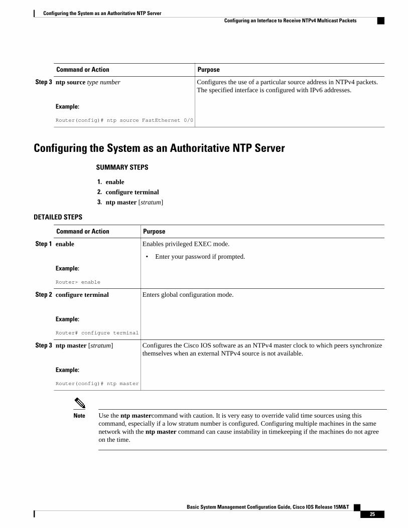
Step 3 ntp source type number
Example:
Router(config)# ntp source FastEthernet 0/0
Configures the use of a particular source address in NTPv4 packets.The specified interface is configured with IPv6 addresses.
Configuring the System as an Authoritative NTP Server
SUMMARY STEPS
1. enable
2. configure terminal
3. ntp master [stratum]
DETAILED STEPS
Command or Action Purpose
Step 1 enable
Example:
Router> enable
Enables privileged EXEC mode.
• Enter your password if prompted.
Step 2 configure terminal
Example:
Router# configure terminal
Enters global configuration mode.
Step 3 ntp master [stratum]
Example:
Router(config)# ntp master
Configures the Cisco IOS software as an NTPv4 master clock to which peers synchronizethemselves when an external NTPv4 source is not available.
Note Use the ntp mastercommand with caution. It is very easy to override valid time sources using thiscommand, especially if a low stratum number is configured. Configuring multiple machines in the samenetwork with the ntp master command can cause instability in timekeeping if the machines do not agreeon the time.
Configuring the System as an Authoritative NTP ServerConfiguring an Interface to Receive NTPv4 Multicast Packets
Basic System Management Configuration Guide, Cisco IOS Release 15M&T 25

Updating the Hardware ClockOn devices that have hardware clocks (system calendars), you can configure the hardware clock to beperiodically updated from the software clock. This is advisable for any device using NTPv4, because thetime and date on the software clock (set using NTPv4) will be more accurate than the hardware clock,because the time setting on the hardware clock has the potential to drift slightly over time.
SUMMARY STEPS
1. enable
2. configure terminal
3. ntp update-calendar
DETAILED STEPS
Command or Action Purpose
Step 1 enable
Example:
Router> enable
Enables privileged EXEC mode.
• Enter your password if prompted.
Step 2 configure terminal
Example:
Router# configure terminal
Enters global configuration mode.
Step 3 ntp update-calendar
Example:
Router(config)# ntp update-calendar
Periodically updates the hardware clock (calendar) from an NTPv4 timesource.
Resetting the Drift Value in the Persistent Data FileThe drift is the frequency offset between the local clock hardware and the authoritative time from theNetwork Time Protocol version 4 (NTPv4) servers. NTPv4 automatically computes this drift and uses it tocompensate permanently for local clock imperfections.
SUMMARY STEPS
1. enable
2. ntp drift clear
Updating the Hardware Clock Configuring an Interface to Receive NTPv4 Multicast Packets
Basic System Management Configuration Guide, Cisco IOS Release 15M&T26

DETAILED STEPS
Command or Action Purpose
Step 1 enable
Example:
Router> enable
Enables privileged EXEC mode.
• Enter your password if prompted.
Step 2 ntp drift clear
Example:
Router# ntp drift clear
Resets the drift value stored in the persistent data file.
Troubleshooting NTPv4 in IPv6
SUMMARY STEPS
1. enable
2. show clock [detail]
3. show ntp associations [detail
4. s how ntp status
5. debug ntp {adjust | authentication | events | loopfilter | packets | params | refclock | select | sync |validity}
DETAILED STEPS
Command or Action Purpose
Step 1 enable
Example:
Router> enable
Enables privileged EXEC mode.
• Enter your password if prompted.
Step 2 show clock [detail]
Example:
Router# show clock
Displays the time and date from the systemsoftware clock.
Troubleshooting NTPv4 in IPv6Configuring an Interface to Receive NTPv4 Multicast Packets
Basic System Management Configuration Guide, Cisco IOS Release 15M&T 27

Command or Action Purpose
Step 3 show ntp associations [detail
Example:
Router# show ntp associations
Shows the status of NTP associations.
Step 4 s how ntp status
Example:
Router# show ntp status
Shows the status of the NTPv4.
Step 5 debug ntp {adjust | authentication | events | loopfilter | packets |params | refclock | select | sync | validity}
Example:
Router# debug ntp
Displays debugging messages for NTPv4features.
Configuration Examples for NTPv4 in IPv6• Example: Defining an NTPv4 Access Group, page 28
Example: Defining an NTPv4 Access GroupIn the following IPv6 example, an NTPv4 access group is enabled and a KOD packet is sent to any hostthat tries to send a packet that is not compliant with the access-group policy:
Router> enableRouter# configure terminalRouter(config)# ntp access-group serve acl1 kod
Additional ReferencesRelated Documents
Related Topic Document Title
IPv6 addressing and connectivity Cisco IOS IPv6 ConfigurationGuide
Example: Defining an NTPv4 Access Group Configuration Examples for NTPv4 in IPv6
Basic System Management Configuration Guide, Cisco IOS Release 15M&T28

Related Topic Document Title
Setting Time and Calendar Services Cisco IOS Basic SystemManagement ConfigurationGuide
Cisco IOS commands Cisco IOS Master Command List,All Releases
IPv6 commands Cisco IOS IPv6 CommandReference
Cisco IOS IPv6 features Cisco IOS IPv6 Feature Mapping
Standards and RFCs
Standard/RFC Title
RFCs for IPv6 IPv6 RFCs
Technical Assistance
Description Link
The Cisco Support and Documentation websiteprovides online resources to downloaddocumentation, software, and tools. Use theseresources to install and configure the software andto troubleshoot and resolve technical issues withCisco products and technologies. Access to mosttools on the Cisco Support and Documentationwebsite requires a Cisco.com user ID andpassword.
http://www.cisco.com/cisco/web/support/index.html
Feature Information for NTPv4 in IPv6The following table provides release information about the feature or features described in this module.This table lists only the software release that introduced support for a given feature in a given softwarerelease train. Unless noted otherwise, subsequent releases of that software release train also support thatfeature.
Use Cisco Feature Navigator to find information about platform support and Cisco software image support.To access Cisco Feature Navigator, go to www.cisco.com/go/cfn. An account on Cisco.com is not required.
Table 2 Feature Information for NTP4 in IPv6
Feature Name Releases Feature Information
NTPv4 with Support for IPv4 andIPv6
15.1(1)SY This feature is supported.
NTPv4 in IPv6Feature Information for NTPv4 in IPv6
Basic System Management Configuration Guide, Cisco IOS Release 15M&T 29

Cisco and the Cisco logo are trademarks or registered trademarks of Cisco and/or its affiliates in the U.S.and other countries. To view a list of Cisco trademarks, go to this URL: www.cisco.com/go/trademarks.Third-party trademarks mentioned are the property of their respective owners. The use of the word partnerdoes not imply a partnership relationship between Cisco and any other company. (1110R)
Any Internet Protocol (IP) addresses and phone numbers used in this document are not intended to beactual addresses and phone numbers. Any examples, command display output, network topology diagrams,and other figures included in the document are shown for illustrative purposes only. Any use of actual IPaddresses or phone numbers in illustrative content is unintentional and coincidental.
NTPv4 in IPv6
Basic System Management Configuration Guide, Cisco IOS Release 15M&T30

Network Time Protocol
Network Time Protocol (NTP) is a protocol designed to time-synchronize a network of machines. NTPruns on User Datagram Protocol (UDP), which in turn runs on IP. NTP Version 3 is documented in RFC1305.
This module describes how to configure Network Time Protocol on Cisco devices.
• Finding Feature Information, page 31• Information About Network Time Protocol, page 31• How to Configure Network Time Protocol, page 39• Configuration Examples for Network Time Protocol, page 57• Additional References for Network Time Protocol, page 57• Feature Information for Network Time Protocol, page 58
Finding Feature InformationYour software release may not support all the features documented in this module. For the latest caveatsand feature information, see Bug Search Tool and the release notes for your platform and software release.To find information about the features documented in this module, and to see a list of the releases in whicheach feature is supported, see the feature information table at the end of this module.
Use Cisco Feature Navigator to find information about platform support and Cisco software image support.To access Cisco Feature Navigator, go to www.cisco.com/go/cfn. An account on Cisco.com is not required.
Information About Network Time Protocol• Time and Calendar Services, page 31• Network Time Protocol, page 32• Simple Network Time Protocol, page 37• VINES Time Service, page 37• Hardware Clock, page 38• Time Ranges, page 38
Time and Calendar ServicesThe primary source for time data on your system is the software clock. This clock runs from the momentthe system starts up and keeps track of the current date and time. The software clock can be set from anumber of sources and in turn can be used to distribute the current time through various mechanisms to
Basic System Management Configuration Guide, Cisco IOS Release 15M&T 31

other systems. When a device with a hardware clock is initialized or rebooted, the software clock is initiallyset based on the time in the hardware clock. The software clock can then be updated from the followingsources:
• Manual configuration (using the hardware clock)• Network Time Protocol (NTP)• Simple Network Time Protocol (SNTP)• Virtual Integrated Network Service (VINES) Time Service
Because the software clock can be dynamically updated, it has the potential to be more accurate than thehardware clock.
The software clock can provide time to the following services:
• Access lists• Logging and debugging messages• NTP• The hardware clock• User show commands• VINES Time Service
Note The software clock cannot provide time to the NTP or VINES Time Service if the clock was set usingSNTP.
The software clock keeps track of time internally based on the Coordinated Universal Time (UTC), alsoknown as Greenwich Mean Time (GMT). You can configure information about the local time zone andsummer time (daylight saving time) so that time is displayed correctly relative to the local time zone.
The software clock keeps track of whether the time is authoritative (that is, whether it has been set by atime source considered to be authoritative). If it is not authoritative, the time will be available only fordisplay purposes and will not be redistributed.
Network Time ProtocolNetwork Time Protocol (NTP) is a protocol designed to time-synchronize a network of machines. NTPruns on UDP, which in turn runs on IP. NTP Version 3 (NTPv3) is documented in RFC 1305.
An NTP network usually gets its time from an authoritative time source such as a radio clock or an atomicclock attached to a time server. NTP then distributes this time across the network. NTP is extremelyefficient; no more than one packet per minute is necessary to synchronize two machines to the accuracy ofwithin a millisecond of one another.
NTP uses the concept of a stratum to describe how many NTP hops away a machine is from anauthoritative time source. A stratum 1 time server typically has an authoritative time source (such as a radioor atomic clock or a Global Positioning System [GPS] time source) directly attached, a stratum 2 timeserver receives its time via NTP from a stratum 1 time server, and so on.
NTP has two ways to avoid synchronizing to a machine whose time may not be accurate. NTP does notsynchronize to a machine that is not in turn synchronized with the NTP. NTP compares the time reportedby several machines and does not synchronize to a machine whose time is significantly different fromothers, even if its stratum is lower. This strategy effectively builds a self-organizing tree of NTP servers.
Our implementation of NTP does not support stratum 1 service; that is, you cannot connect to a radio oratomic clock (for some specific platforms, however, you can connect to a GPS time-source device). We
Network Time Protocol Information About Network Time Protocol
Basic System Management Configuration Guide, Cisco IOS Release 15M&T32

recommend that the time service you derive for your network from the public NTP servers that areavailable in the IP Internet.
If the network is isolated from the Internet, our implementation of NTP allows a machine to be configuredso that it acts as though it is synchronized via NTP, when in fact the network has determined the time byusing other means. Other machines can then synchronize to that machine via NTP.
A number of manufacturers include NTP software for their host systems and a publicly available versionfor systems running UNIX. This software also allows UNIX-derivative servers to acquire the time directlyfrom an atomic clock, which would subsequently propagate time information along to Cisco devices.
The communication between machines running NTP (known as associations) are usually staticallyconfigured; each machine is given the IP address of all machines with which it should form associations.Accurate timekeeping is made possible through exchange of NTP messages between each pair of machineswith an association.
However, in a LAN environment, NTP can be configured to use IP broadcast messages instead. Thisalternative reduces configuration complexity because each machine can be configured to send or receivebroadcast messages. However, the accuracy of timekeeping is marginally reduced because the informationflow is only one way.
The time kept on a machine is a critical resource, so we strongly recommend that you use the securityfeatures of NTP to avoid the accidental or malicious setting of incorrect time. Two security mechanisms areavailable: an access-list-based restriction scheme and an encrypted authentication mechanism.
When multiple sources of time (VINES, hardware clock, manual configuration) are available, NTP isalways considered to be more authoritative. NTP time overrides the time set by any other method.
NTP services are disabled on all interfaces by default.
For more information about NTP, see the following sections:
• Poll-Based NTP Associations, page 33• Broadcast-Based NTP Associations, page 34• NTP Access Group, page 34• NTP Services on a Specific Interface, page 35• Source IP Address for NTP Packets, page 35• System as an Authoritative NTP Server, page 36• Orphan Mode, page 36
Poll-Based NTP AssociationsNetworking devices running NTP can be configured to operate in variety of association modes whensynchronizing time with reference time sources. A networking device can obtain time information on anetwork in two ways—by polling host servers and by listening to NTP broadcasts. This section focuses onthe poll-based association modes. Broadcast-based NTP associations are discussed in the Broadcast-BasedNTP Associations section.
The following are the two most commonly used poll-based association modes:
• Client mode• Symmetric active mode
The client and the symmetric active modes should be used when NTP is required to provide a high level oftime accuracy and reliability.
When a networking device is operating in the client mode, it polls its assigned time-serving hosts for thecurrent time. The networking device will then pick a host from among all the polled time servers to
Network Time ProtocolPoll-Based NTP Associations
Basic System Management Configuration Guide, Cisco IOS Release 15M&T 33

synchronize with. Because the relationship that is established in this case is a client-host relationship, thehost will not capture or use any time information sent by the local client device. This mode is most suitedfor file-server and workstation clients that are not required to provide any form of time synchronization toother local clients. Use the ntp server command to individually specify the time server that you want yournetworking device to consider synchronizing with and to set your networking device to operate in the clientmode.
When a networking device is operating in the symmetric active mode, it polls its assigned time-servinghosts for the current time and it responds to polls by its hosts. Because this is a peer-to-peer relationship,the host will also retain time-related information of the local networking device that it is communicatingwith. This mode should be used when a number of mutually redundant servers are interconnected viadiverse network paths. Most stratum 1 and stratum 2 servers on the Internet adopt this form of networksetup. Use the ntp peer command to individually specify the time serving hosts that you want yournetworking device to consider synchronizing with and to set your networking device to operate in thesymmetric active mode.
The specific mode that you should set for each of your networking devices depends primarily on the rolethat you want them to assume as a timekeeping device (server or client) and the device’s proximity to astratum 1 timekeeping server.
A networking device engages in polling when it is operating as a client or a host in the client mode or whenit is acting as a peer in the symmetric active mode. Although polling does not usually place a burden onmemory and CPU resources such as bandwidth, an exceedingly large number of ongoing and simultaneouspolls on a system can seriously impact the performance of a system or slow the performance of a givennetwork. To avoid having an excessive number of ongoing polls on a network, you should limit the numberof direct, peer-to-peer or client-to-server associations. Instead, you should consider using NTP broadcaststo propagate time information within a localized network.
Broadcast-Based NTP AssociationsBroadcast-based NTP associations should be used when time accuracy and reliability requirements aremodest and if your network is localized and has more than 20 clients. Broadcast-based NTP associationsare also recommended for use on networks that have limited bandwidth, system memory, or CPUresources.
A networking device operating in the broadcast client mode does not engage in any polling. Instead, itlistens for NTP broadcast packets that are transmitted by broadcast time servers. Consequently, timeaccuracy can be marginally reduced because time information flows only one way.
Use the ntp broadcast client command to set your networking device to listen for NTP broadcast packetspropagated through a network. For broadcast client mode to work, the broadcast server and its clients mustbe located on the same subnet. You must enable the time server that transmits NTP broadcast packets onthe interface of the given device by using the ntp broadcast command.
NTP Access GroupThe access list-based restriction scheme allows you to grant or deny certain access privileges to an entirenetwork, a subnet within a network, or a host within a subnet. To define an NTP access group, use the ntpaccess-group command in global configuration mode.
The access group options are scanned in the following order, from least restrictive to the most restrictive:
1 ipv4—Configures IPv4 access lists.2 ipv6—Configures IPv6 access lists.
Network Time Protocol Broadcast-Based NTP Associations
Basic System Management Configuration Guide, Cisco IOS Release 15M&T34

3 peer—Allows time requests and NTP control queries, and allows the system to synchronize itself to asystem whose address passes the access list criteria.
4 serve—Allows time requests and NTP control queries, but does not allow the system to synchronizeitself to a system whose address passes the access list criteria.
5 serve-only—Allows only time requests from a system whose address passes the access list criteria.6 query-only—Allows only NTP control queries from a system whose address passes the access list
criteria.
If the source IP address matches the access lists for more than one access type, the first type is grantedaccess. If no access groups are specified, all access types are granted access to all systems. If any accessgroups are specified, only the specified access types will be granted access.
For details on NTP control queries, see RFC 1305 (NTP Version 3).
The encrypted NTP authentication scheme should be used when a reliable form of access control isrequired. Unlike the access list-based restriction scheme that is based on IP addresses, the encryptedauthentication scheme uses authentication keys and an authentication process to determine if NTPsynchronization packets sent by designated peers or servers on a local network are deemed as trusted beforethe time information that they carry along with them is accepted.
The authentication process begins from the moment an NTP packet is created. Cryptographic checksumkeys are generated using the message digest algorithm 5 (MD5) and are embedded into the NTPsynchronization packet that is sent to a receiving client. Once a packet is received by a client, itscryptographic checksum key is decrypted and checked against a list of trusted keys. If the packet contains amatching authentication key, the time-stamp information that is contained within the packet is accepted bythe receiving client. NTP synchronization packets that do not contain a matching authenticator key areignored.
Note In large networks, where many trusted keys must be configured, the Range of Trusted Key Configurationfeature enables configuring multiple keys simultaneously.
It is important to note that the encryption and decryption processes used in NTP authentication can be veryCPU-intensive and can seriously degrade the accuracy of the time that is propagated within a network. Ifyour network setup permits a more comprehensive model of access control, you should consider the use ofthe access list-based form of control.
After NTP authentication is properly configured, your networking device will synchronize with andprovide synchronization only to trusted time sources.
NTP Services on a Specific InterfaceNetwork Time Protocol (NTP) services are disabled on all interfaces by default. NTP is enabled globallywhen any NTP commands are entered. You can selectively prevent NTP packets from being receivedthrough a specific interface by using the ntp disable command in interface configuration mode.
Source IP Address for NTP PacketsWhen the system sends an NTP packet, the source IP address is normally set to the address of the interfacethrough which the NTP packet is sent. Use the ntp source interface command in global configuration modeto configure a specific interface from which the IP source address will be taken.
This interface will be used for the source address for all packets sent to all destinations. If a source addressis to be used for a specific association, use the source keyword in the ntp peer or ntp server command.
Network Time ProtocolNTP Services on a Specific Interface
Basic System Management Configuration Guide, Cisco IOS Release 15M&T 35

System as an Authoritative NTP ServerUse the ntp master command in global configuration mode if you want the system to be an authoritativeNTP server, even if the system is not synchronized to an outside time source.
Note Use the ntp master command with caution. It is very easy to override valid time sources using thiscommand, especially if a low stratum number is configured. Configuring multiple machines in the samenetwork with the ntp master command can cause instability in timekeeping if the machines do not agreeon the time.
Orphan ModeThe NTP subnet is sometimes isolated from local reference clocks or Internet clock servers. During thisperiod of isolation, the subnet servers and clients are synchronized to a common time scale. The local clockdriver simulates a UTC source to provide a common time scale. A server connected to the driver directly orindirectly synchronizes the other hosts in the subnet.
Using a local clock driver may sometimes result in irrecoverable failures of the subnet, and maintainingredundancy using multiple servers is not feasible. The Orphan Mode feature, which does not have any suchdisadvantages, eliminates the need for a local clock driver. The Orphan Mode feature provides a singlesimulated UTC source with multiple servers and a seamless switching mechanism as servers recover from afailure.
In private networks, one or multiple core servers operating at the lowest stratum is normally included. Youmust configure each of these servers as backups for other servers using symmetric or broadcast modes.Even if one core server reaches a UTC source, the entire subnet synchronizes to the simulating server. Ifnone of the servers reach a UTC source, one of the servers, which is known as the orphan parent, cansimulate a UTC source, and serve as the simulated UTC source for all the other hosts, known as orphanchildren, in the subnet.
Use the ntp orphan stratum command to enable a host for orphan mode, where stratum is a stratum valueless than 16 and greater than any stratum value that occurs in the configured Internet time servers.However, you must provide sufficient stratums so that every subnet host dependent on the orphan childrenhas a stratum value less than 16. If no associations for other servers or reference clocks are configured, youmust set the orphan stratum value to 1.
An orphan parent operating at stratum 1 with no sources displays the reference ID LOOP. An orphan parentnot operating at stratum 1 displays the UNIX loopback address 127.0.0.1. Ordinary NTP clients use aselection metric based on delay and dispersion, whereas orphan children use a metric computed from the IPaddress of each core server in the subnet. Each orphan child selects the orphan parent with the smallestmetric as the root server.
A server that loses all sources, continuously synchronizes the local clock driver with other servers, thusbacking up the server. Enable orphan mode only in core servers and orphan children.
Network Time Protocol System as an Authoritative NTP Server
Basic System Management Configuration Guide, Cisco IOS Release 15M&T36

The following figure illustrates how orphan mode is set up, and a peer network configuration, where twoprimary or secondary (stratum 2) servers are configured with reference clocks or public Internet primaryservers, with each using symmetric modes.
Figure 1 Orphan Mode Setup
• Prerequisites for Orphan Mode, page 37
Prerequisites for Orphan Mode
To ensure smooth function of the orphan mode, you must configure each core server with available sourcesto operate at the same stratum. Configure the ntp orphan command in all the core servers and the orphanchildren. Configure each orphan child with all root servers.
Simple Network Time ProtocolSimple Network Time Protocol (SNTP) is a simplified, client-only version of NTP. SNTP can receive onlythe time from NTP servers; it cannot be used to provide time services to other systems.
SNTP typically provides time within 100 milliseconds of the accurate time, but it does not provide thecomplex filtering and statistical mechanisms of NTP. In addition, SNTP does not authenticate traffic,although you can configure extended access lists to provide some protection. An SNTP client is morevulnerable to servers that have unexpected behavior than an NTP client, and should be used only insituations where strong authentication is not required.
You can configure SNTP to request and accept packets from configured servers or to accept NTP broadcastpackets from any source. When multiple sources are sending NTP packets, the server with the best stratumis selected. (See the Network Time Protocol section on page 3 for a description of strata.) If multipleservers are at the same stratum, a configured server is preferred over a broadcast server. If multiple serverspass both tests, the first one to send a time packet is selected. SNTP will choose a new server only if itstops receiving packets from the currently selected server, or if a better server (according to the criteriadescribed) is discovered.
VINES Time ServiceTime service is available when Banyan VINES is configured. This protocol is a standard part of VINES.The Cisco implementation allows the VINES time service to be used in two ways. First, if the system haslearned the time from some other source, it can act as a VINES time server and provide time to other
Simple Network Time ProtocolPrerequisites for Orphan Mode
Basic System Management Configuration Guide, Cisco IOS Release 15M&T 37

machines running VINES. Second, it can use the VINES time service to set the software clock if no otherform of time service is available.
Note Support for Banyan VINES and Xerox Network Systems (XNS) is not available in all releases.
Hardware ClockSome devices contain a battery-powered hardware clock that tracks the date and time across system restartsand power outages. The hardware clock is always used to initialize the software clock when the system isrestarted.
Note Within the CLI command syntax, the hardware clock is referred to as the system calendar.
If no other source is available, the hardware clock can be considered as an authoritative source of time andbe redistributed via NTP. If NTP is running, the hardware clock can be updated periodically from NTP,compensating for the inherent drift, which is the consistent gain or loss of time at a certain rate if thehardware clock is left to run.
You can configure a hardware clock (system calendar) on any device to be periodically updated from thesoftware clock. We recommend that you use this configuration for any device using NTP, because the timeand date on the software clock (set using NTP) will be more accurate than the hardware clock, because thetime setting on the hardware clock has the potential to drift slightly over time.
Use the ntp update-calendar command in global configuration mode if a routing device is synchronized toan outside time source via NTP and you want the hardware clock to be synchronized to NTP time.
Time RangesThe Cisco software allows implementation of features based on the time of day. The time-range globalconfiguration command defines specific times of the day and week, which can then be referenced by afunction, so that those time restrictions are imposed on the function itself.
Depending on your release, IP and Internetwork Packet Exchange (IPX) extended access lists are the onlyfunctions that can use time ranges. The time range allows the network administrator to define when thepermit or deny statements in the access list are in effect. Prior to the introduction of this feature, access liststatements were always in effect once they were applied. Both named and numbered access lists canreference a time range.
Note The time range relies on the system’s software clock. For the time range feature to work the way youintend, you need a reliable clock source. We recommend that you use NTP to synchronize the system’ssoftware clock.
Benefits of time ranges include the following:
• The network administrator has more control over permitting or denying a user access to resources.These resources could be an application (identified by an IP address/mask pair and a port number),policy routing, or an on-demand link (identified as interesting traffic to the dialer).
• Network administrators can set a time-based security policy, including the following:
Hardware Clock Prerequisites for Orphan Mode
Basic System Management Configuration Guide, Cisco IOS Release 15M&T38

◦ Perimeter security using the Cisco Firewall feature set or access lists.◦ Data confidentiality with Cisco Encryption Technology or IP security.
• Policy-based routing and queueing functions are enhanced.• When provider access rates vary by time of day, traffic can be rerouted automatically and cost-
effectively.• Service providers can dynamically change a committed access rate (CAR) configuration to support the
quality of service (QoS) service level agreements (SLAs) that are negotiated for certain times of theday.
Network administrators can control logging messages. Access list entries can log traffic at certain times ofthe day, but not constantly. Therefore, administrators can deny access without the need to analyze the manylogs generated during peak hours.
How to Configure Network Time Protocol• Configuring NTP, page 39• Configuring SNTP, page 47• Configuring VINES Time Service, page 48• Configuring the Time and Date, page 49• Setting the Hardware Clock, page 51• Configuring Time Ranges, page 54• Verifying Network Time Protocol, page 55
Configuring NTP
• Restrictions for Network Time Protocol, page 39• Configuring Poll-Based NTP Associations, page 40• Configuring Broadcast-Based NTP Associations, page 41• Configuring NTP Authentication, page 42• Configuring an External Reference Clock, page 44• Configuring Orphan Mode, page 46
Restrictions for Network Time ProtocolThe Network Time Protocol (NTP) package contains a vulnerability that could allow an unauthenticated,remote attacker to cause a denial of service (DoS) condition. NTP versions 4.2.4p7 and earlier arevulnerable.
The vulnerability is due to an error in handling of certain malformed messages. An unauthenticated, remoteattacker could send a malicious NTP packet with a spoofed source IP address to a vulnerable host. The hostthat processes the packet sends a response packet back to the transmitter. This action could start a loop ofmessages between the two hosts that could cause both the hosts to consume excessive CPU resources, useup the disk space by writing messages to log files, and consume the network bandwidth. All of these couldcause a DoS condition on the affected hosts.
For more information, see the Network Time Protocol Package Remote Message Loop Denial of ServiceVulnerability web page.
Configuring NTPHow to Configure Network Time Protocol
Basic System Management Configuration Guide, Cisco IOS Release 15M&T 39

Cisco software releases that support NTPv4 are not affected. All other versions of Cisco software areaffected.
To display whether a device is configured with NTP, use the show running-config | include ntpcommand. If the output returns any of the following commands, then that device is vulnerable to the attack:
• ntp broadcast client• ntp master• ntp multicast client• ntp peer• ntp server
For more information on understanding Cisco software releases, see the White Paper: Cisco IOS and NX-OS Software Reference Guide.
There are no workarounds for this vulnerability other than disabling NTP on the device. Only packetsdestined for any configured IP address on the device can exploit this vulnerability. Transit traffic will notexploit this vulnerability.
Depending on your release, your feature will process NTP mode 7 packets and will display the message“NTP: Receive: dropping message: Received NTP private mode 7 packet ” if debugs for NTP are enabled.Configure the ntp allow mode private command to process NTP mode 7 packets. This command isdisabled by default.
Note NTP peer authentication is not a workaround and is a vulnerable configuration.
NTP services are disabled on all interfaces by default.
Networking devices running NTP can be configured to operate in a variety of association modes whensynchronizing time with reference time sources. A networking device can obtain time information on anetwork in two ways: by polling host servers and by listening to NTP broadcasts.
Configuring Poll-Based NTP Associations
SUMMARY STEPS
1. enable
2. configure terminal
3. ntp peer ip-address [normal-sync] [version number] [key key-id] [prefer]
4. ntp server ip-address [version number] [key key-id] [prefer]
5. end
Network Time Protocol Configuring Poll-Based NTP Associations
Basic System Management Configuration Guide, Cisco IOS Release 15M&T40

DETAILED STEPS
Command or Action Purpose
Step 1 enable
Example:
Device> enable
Enables privileged EXEC mode.
• Enter your password if prompted.
Step 2 configure terminal
Example:
Device# configure terminal
Enters global configuration mode.
Step 3 ntp peer ip-address [normal-sync] [version number] [key key-id][prefer]
Example:
Device(config)# ntp peer 192.168.10.1 normal-sync version 2 prefer
Forms a peer association with another system.
Step 4 ntp server ip-address [version number] [key key-id] [prefer]
Example:
Device(config)# ntp server 192.168.10.1 version 2 prefer
Forms a server association with another system.
Step 5 end
Example:
Device(config)# end
Exits global configuration mode and returns toprivileged EXEC mode.
Configuring Broadcast-Based NTP Associations
SUMMARY STEPS
1. enable
2. configure terminal
3. interface type number
4. ntp broadcast version number
5. ntp broadcast client
6. ntp broadcastdelay microseconds
7. end
Network Time ProtocolConfiguring Broadcast-Based NTP Associations
Basic System Management Configuration Guide, Cisco IOS Release 15M&T 41

DETAILED STEPS
Command or Action Purpose
Step 1 enable
Example:
Device> enable
Enables privileged EXEC mode.
• Enter your password if prompted.
Step 2 configure terminal
Example:
Device# configure terminal
Enters global configuration mode.
Step 3 interface type number
Example:
Device(config)# interface ethernet 0/0
Configures an interface and enters interface configuration mode.
Step 4 ntp broadcast version number
Example:
Device(config-if)# ntp broadcast version 2
Configures the specified interface to send NTP broadcast packets.
Step 5 ntp broadcast client
Example:
Device(config-if)# ntp broadcast client
Configures the specified interface to receive NTP broadcast packets.
Step 6 ntp broadcastdelay microseconds
Example:
Device(config-if)# ntp broadcastdelay 100
Adjusts the estimated round-trip delay for NTP broadcasts.
Step 7 end
Example:
Device(config-if)# end
Exits interface configuration mode and returns to privileged EXECmode.
Configuring NTP Authentication
Network Time Protocol Configuring NTP Authentication
Basic System Management Configuration Guide, Cisco IOS Release 15M&T42

SUMMARY STEPS
1. enable
2. configure terminal
3. ntp authenticate
4. ntp authentication-key number md5 key
5. ntp authentication-key number md5 key
6. ntp authentication-key number md5 key
7. ntp trusted-key key-number [- end-key]
8. ntp server ip-address key key-id
9. end
DETAILED STEPS
Command or Action Purpose
Step 1 enable
Example:
Device> enable
Enables privileged EXEC mode.
• Enter your password if prompted.
Step 2 configure terminal
Example:
Device# configure terminal
Enters global configuration mode.
Step 3 ntp authenticate
Example:
Device(config)# ntp authenticate
Enables the NTP Authentication feature.
Step 4 ntp authentication-key number md5 key
Example:
Device(config)# ntp authentication-key 1 md5 key1
Defines authentication keys.
• Each key has a key number, a type, and a value.
Step 5 ntp authentication-key number md5 key
Example:
Device(config)# ntp authentication-key 2 md5 key2
Defines authentication keys.
Network Time ProtocolConfiguring NTP Authentication
Basic System Management Configuration Guide, Cisco IOS Release 15M&T 43

Command or Action Purpose
Step 6 ntp authentication-key number md5 key
Example:
Device(config)# ntp authentication-key 3 md5 key3
Defines authentication keys.
Step 7 ntp trusted-key key-number [- end-key]
Example:
Device(config)# ntp trusted-key 1 - 3
Defines trusted authentication keys.
• If a key is trusted, this device will be ready tosynchronize to a system that uses this key in its NTPpackets.
Step 8 ntp server ip-address key key-id
Example:
Device(config)# ntp server 172.16.22.44 key 2
Allows the software clock to be synchronized by an NTP timeserver.
Step 9 end
Example:
Device(config)# end
Exits global configuration mode and returns to privilegedEXEC mode.
Configuring an External Reference Clock
SUMMARY STEPS
1. enable
2. configure terminal
3. line aux line-number
4. ntp refclock trimble pps none stratum number
5. end
6. show ntp associations
7. show ntp status
8. debug ntp refclock
Network Time Protocol Configuring an External Reference Clock
Basic System Management Configuration Guide, Cisco IOS Release 15M&T44

DETAILED STEPS
Command or Action Purpose
Step 1 enable
Example:
Device> enable
Enables privileged EXEC mode.
• Enter your password if prompted.
Step 2 configure terminal
Example:
Device# configure terminal
Enters global configuration mode.
Step 3 line aux line-number
Example:
Device(config)# line aux 0
Enters line configuration mode for the auxiliary port 0.
Step 4 ntp refclock trimble pps none stratumnumber
Example:
Device(config-line)# ntp refclock trimble pps none stratum 1
Configures an external reference clock.
• To configure a Trimble Palisade GPS product connected to theauxiliary port of a Cisco 7200 series device as the NTP referenceclock, use the ntp refclock trimble pps none stratum form of thecommand. Use this command to enable the driver that allows theTrimble Palisade NTP Synchronization Kit to be used as the NTPreference clock source (Cisco 7200 series device only).
• To configure a pulse per second signal (PPS) as the source for NTPsynchronization, use the ntp refclock trimble pps command.
Step 5 end
Example:
Device(config-line)# end
Exits line configuration mode and returns to privileged EXEC mode.
Step 6 show ntp associations
Example:
Device# show ntp associations
Displays the status of NTP associations, including the status of the GPSreference clock.
Network Time ProtocolConfiguring an External Reference Clock
Basic System Management Configuration Guide, Cisco IOS Release 15M&T 45

Command or Action Purpose
Step 7 show ntp status
Example:
Device# show ntp status
Displays the status of NTP.
Step 8 debug ntp refclock
Example:
Device# debug ntp refclock
Allows advanced monitoring of reference clock activities for thepurposes of debugging.
Configuring Orphan ModeTo configure orphan mode, you would require at least two clients. The following task shows how toconfigure orphan mode on one client. Repeat the steps in the other client.
SUMMARY STEPS
1. enable
2. configure terminal
3. ntp server ip-address
4. ntp peer ip-address
5. ntp orphan stratum
6. Repeat steps 1 to 5 on the other client.
DETAILED STEPS
Command or Action Purpose
Step 1 enable
Example:
Router> enable
Enables privileged EXEC mode.
• Enter your password if prompted.
Step 2 configure terminal
Example:Router# configure terminal
Enters global configuration mode.
Network Time Protocol Configuring Orphan Mode
Basic System Management Configuration Guide, Cisco IOS Release 15M&T46

Command or Action Purpose
Step 3 ntp server ip-address
Example:Router(config)# ntp server 10.1.1.1
Forms a server association with another system.
Step 4 ntp peer ip-address
Example:Router(config)# ntp peer 172.16.0.1
Forms a peer association with another system.
Note Use an IP address that is different from the one you just configured,such as 172.16.0.2, while configuring the peer in the other client.
Step 5 ntp orphan stratum
Example:Router(config)# ntp orphan 4
Enables orphan mode in the host.
Step 6 Repeat steps 1 to 5 on the other client.
Configuring SNTPSNTP generally is supported on those platforms that do not provide support for NTP. SNTP is disabled bydefault. To configure SNTP, perform the following task.
SUMMARY STEPS
1. enable
2. configure terminal
3. sntp server {address | hostname} [version number]
4. sntp broadcast client
5. exit
6. show sntp
DETAILED STEPS
Command or Action Purpose
Step 1 enable
Example:
Device> enable
Enables privileged EXEC mode.
• Enter your password if prompted.
Configuring SNTPConfiguring Orphan Mode
Basic System Management Configuration Guide, Cisco IOS Release 15M&T 47

Command or Action Purpose
Step 2 configure terminal
Example:
Device# configure terminal
Enters global configuration mode.
Step 3 sntp server {address | hostname} [version number]
Example:
Device(config)# sntp server 192.168.2.1 version 2
Configures SNTP to request NTP packets from an NTP server.
• Enter the sntp server command once for each NTP server. TheNTP servers must be configured to respond to the SNTPmessages from the device.
Step 4 sntp broadcast client
Example:
Device(config)# sntp broadcast client
Configures SNTP to accept NTP packets from any NTP broadcastserver.
Note If you enter both the sntp server command and the sntpbroadcast client command, the device will accept time from abroadcast server but will prefer time from a configured server,assuming that the strata are equal.
Step 5 exit
Example:
Device(config)# exit
Exits global configuration mode and returns to privileged EXECmode.
Step 6 show sntp
Example:
Device# show sntp
Displays information about SNTP.
Configuring VINES Time ServiceTime service is available when Banyan VINES is configured. This protocol is a standard part of VINES.Perform the following task to configure VINES Time Service.
Note Depending on your release, the Banyan VINES and XNS is available in the Cisco software. The vines timeset-system and vines time use-system commands are not available in some releases.
Configuring VINES Time Service Configuring Orphan Mode
Basic System Management Configuration Guide, Cisco IOS Release 15M&T48

SUMMARY STEPS
1. enable
2. configure terminal
3. vines time use-system
4. vines time set-system
5. exit
DETAILED STEPS
Command or Action Purpose
Step 1 enable
Example:
Device> enable
Enables privileged EXEC mode.
• Enter your password if prompted.
Step 2 configure terminal
Example:
Device# configure terminal
Enters global configuration mode.
Step 3 vines time use-system
Example:
Device(config)# vines time use-system
Distributes the system software clock time to other VINES systems.
Step 4 vines time set-system
Example:
Device(config)# vines time set-system
Sets the software clock system time and date as derived from VINES timeservices.
Step 5 exit
Example:
Device(config)# exit
Exits global configuration mode and returns to privileged EXEC mode.
Configuring the Time and DateIf no other source of time is available, you can manually configure the current time and date after thesystem is restarted. The time will remain accurate until the next system restart. We recommend that you usemanual configuration only as a last resort.
Configuring the Time and DateConfiguring Orphan Mode
Basic System Management Configuration Guide, Cisco IOS Release 15M&T 49

If you have an outside source to which the device can synchronize, you need not manually set the softwareclock. Perform the following task to configure the time and date manually.
SUMMARY STEPS
1. enable
2. configure terminal
3. clock timezone zone hours-offset [minutes-offset]
4. clock summer-time zone recurring [week day month hh:mm week day month hh:mm [offset]]
5. clock summer-time zone date date month year hh:mm date month year hh:mm [offset]
6. exit
7. clock set hh:mm:ss date month year
DETAILED STEPS
Command or Action Purpose
Step 1 enable
Example:
Device> enable
Enables privileged EXEC mode.
• Enter your password if prompted.
Step 2 configure terminal
Example:
Device# configure terminal
Enters global configuration mode.
Step 3 clock timezone zone hours-offset [minutes-offset]
Example:
Device(config)# clock timezone PST 2 30
Configures the time zone used by the Cisco software.
Note The minutes-offset argument of the clock timezone commandis available for those cases where a local time zone is apercentage of an hour different from UTC/GMT. Forexample, the time zone for some sections of Atlantic Canada(AST) is UTC –3.5. In this case, the necessary commandwould be clock timezone AST –3 30.
Step 4 clock summer-time zone recurring [week daymonth hh:mm week day month hh:mm [offset]]
Example:
Device(config)# clock summer-time PST recurring 1 monday january 12:12 4 Tuesday december 12:12 120
Configures summer time (daylight saving time) in areas where itstarts and ends on a particular day of the week each year.
Network Time Protocol Configuring Orphan Mode
Basic System Management Configuration Guide, Cisco IOS Release 15M&T50

Command or Action Purpose
Step 5 clock summer-time zone date date month yearhh:mm date month year hh:mm [offset]
Example:
Device(config)# clock summer-time PST date 1 january 1999 12:12 4 december 2001 12:12 120
Configures a specific summer time start and end date.
• The offset argument is used to indicate the number of minutesto add to the clock during summer time.
Step 6 exit
Example:
Device(config)# exit
Exits global configuration mode and returns to privileged EXECmode.
Step 7 clock set hh:mm:ss date month year
Example:
Device# clock set 12:12:12 1 january 2011
Sets the software clock.
• Use this command if no other time sources are available. Thetime specified in this command is relative to the configuredtime zone.
Note Generally, if the system is synchronized by a valid outsidetiming mechanism, such as an NTP or VINES clock source,or if you have a device with a hardware clock, you need notset the software clock.
Setting the Hardware ClockMost Cisco devices have a separate hardware-based clock in addition to the software-based clock. Thehardware clock is a chip with a rechargeable backup battery that can retain the time and date informationacross reboots of the device.
To maintain the most accurate time update from an authoritative time source on the network, the softwareclock should receive time updates from an authoritative time on the network. The hardware clock should inturn be updated at regular intervals from the software clock while the system is running.
The hardware clock (system calendar) maintains time separately from the software clock. The hardwareclock continues to run when the system is restarted or when the power is turned off. Typically, thehardware clock needs to be manually set only once, when the system is installed.
You should avoid setting the hardware clock if you have access to a reliable external time source. Timesynchronization should instead be established using NTP.
Perform the following task to set the hardware clock.
Note Depending on your release, NTP runs within IOS daemon (IOSd), which updates the time on the Linuxkernel. As the Linux kernel updates the hardware clock every 11 minutes, NTP does not interact with thehardware clock directly. So, the calendar-related commands are not required.
Setting the Hardware ClockConfiguring Orphan Mode
Basic System Management Configuration Guide, Cisco IOS Release 15M&T 51

SUMMARY STEPS
1. enable
2. calendar set hh:mm:ss day month year
3. configure terminal
4. clock calendar-valid
5. exit
6. clock read-calendar
7. clock update-calendar
8. show calendar
9. show clock [detail]
10. show ntp associations [detail]
11. show ntp status
12. show sntp
DETAILED STEPS
Command or Action Purpose
Step 1 enable
Example:
Device> enable
Enables privileged EXEC mode.
• Enter your password if prompted.
Step 2 calendar set hh:mm:ss day month year
Example:
Device# calendar set 10:12:15 monday june 1999
Sets the hardware clock.
Note Use this command when you have no access to anexternal time source.
Step 3 configure terminal
Example:
Device# configure terminal
Enters global configuration mode.
Step 4 clock calendar-valid
Example:
Device(config)# clock calendar-valid
Enables the device to act as a valid time source to whichnetwork peers can synchronize.
• By default, the time maintained on the software clock is notconsidered to be reliable and will not be synchronized withNTP or VINES time service. To set the hardware clock as avalid time source, use this command.
Network Time Protocol Configuring Orphan Mode
Basic System Management Configuration Guide, Cisco IOS Release 15M&T52

Command or Action Purpose
Step 5 exit
Example:
Device(config)# exit
Exits global configuration mode and returns to privileged EXECmode.
Step 6 clock read-calendar
Example:
Device# clock read-calendar
Sets the software clock to the new hardware clock setting.
Step 7 clock update-calendar
Example:
Device# clock update-calendar
Updates the hardware clock with a new software clock setting.
Step 8 show calendar
Example:
Device# show calendar
Displays the current hardware clock time.
Step 9 show clock [detail]
Example:
Device# show clock detail
Displays the current software clock time.
Step 10 show ntp associations [detail]
Example:
Device# show ntp associations detail
Displays the status of NTP associations.
Step 11 show ntp status
Example:
Device# show ntp status
Displays the status of NTP.
Network Time ProtocolConfiguring Orphan Mode
Basic System Management Configuration Guide, Cisco IOS Release 15M&T 53

Command or Action Purpose
Step 12 show sntp
Example:
Device# show sntp
Displays information about SNTP.
Configuring Time Ranges
SUMMARY STEPS
1. enable
2. configure terminal
3. time-range time-range-name
4. Enter one of the following:
• absolute [start hh:mm date month year] [end hh:mm date month year]• periodic day-of-the-week hh:mm to [day-of-the-week] hh:mm
5. end
DETAILED STEPS
Command or Action Purpose
Step 1 enable
Example:
Device> enable
Enables privileged EXEC mode.
• Enter your password if prompted.
Step 2 configure terminal
Example:
Device# configure terminal
Enters global configuration mode.
Step 3 time-range time-range-name
Example:
Device(config)# time-range range1
Assigns a name to the time range to be configured andenters time range configuration mode.
Configuring Time Ranges Configuring Orphan Mode
Basic System Management Configuration Guide, Cisco IOS Release 15M&T54
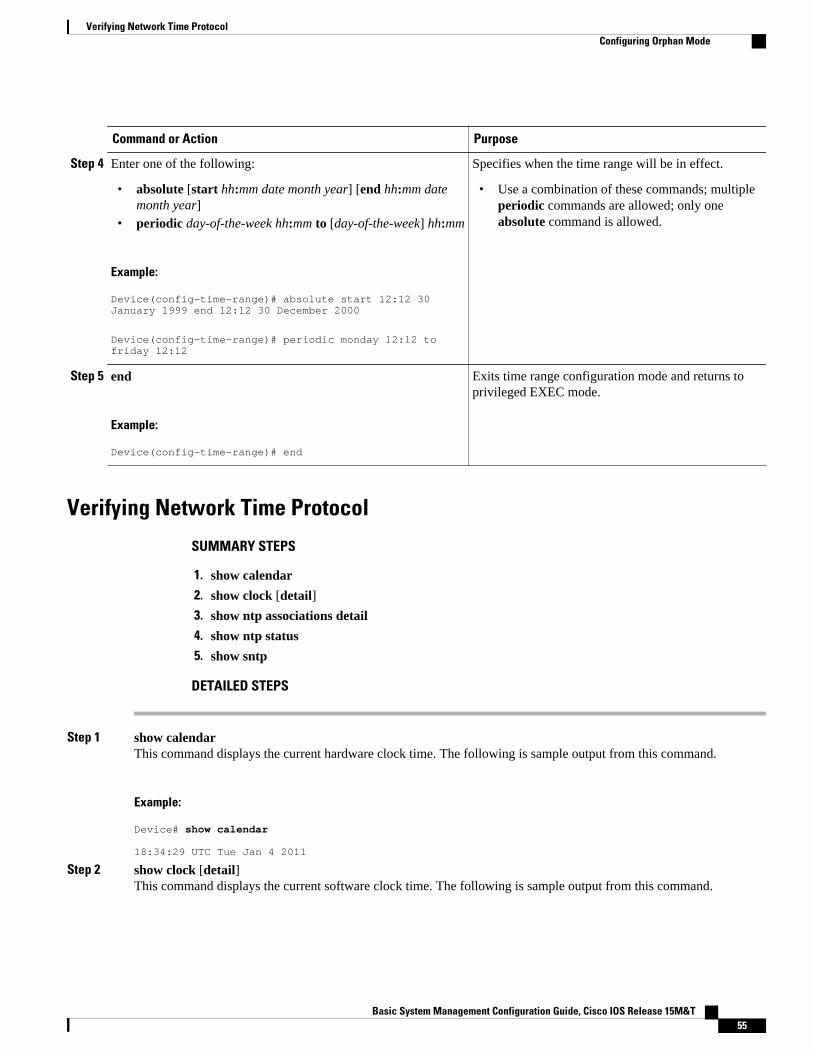
Command or Action Purpose
Step 4 Enter one of the following:
• absolute [start hh:mm date month year] [end hh:mm datemonth year]
• periodic day-of-the-week hh:mm to [day-of-the-week] hh:mm
Example:
Device(config-time-range)# absolute start 12:12 30 January 1999 end 12:12 30 December 2000
Device(config-time-range)# periodic monday 12:12 to friday 12:12
Specifies when the time range will be in effect.
• Use a combination of these commands; multiple periodic commands are allowed; only oneabsolute command is allowed.
Step 5 end
Example:
Device(config-time-range)# end
Exits time range configuration mode and returns toprivileged EXEC mode.
Verifying Network Time Protocol
SUMMARY STEPS
1. show calendar
2. show clock [detail]
3. show ntp associations detail
4. show ntp status
5. show sntp
DETAILED STEPS
Step 1 show calendarThis command displays the current hardware clock time. The following is sample output from this command.
Example:
Device# show calendar
18:34:29 UTC Tue Jan 4 2011
Step 2 show clock [detail]This command displays the current software clock time. The following is sample output from this command.
Verifying Network Time ProtocolConfiguring Orphan Mode
Basic System Management Configuration Guide, Cisco IOS Release 15M&T 55

Example:
Device# show clock detail
*18:38:21.655 UTC Tue Jan 4 2011Time source is hardware calendar
Step 3 show ntp associations detailThis command displays the status of NTP associations. The following is sample output from this command.
Example:
Device# show ntp associations detail
192.168.10.1 configured, insane, invalid, unsynced, stratum 16ref ID .INIT., time 00000000.00000000 (00:00:00.000 UTC Mon Jan 1 1900)our mode active, peer mode unspec, our poll intvl 64, peer poll intvl 1024root delay 0.00 msec, root disp 0.00, reach 0, sync dist 15940.56delay 0.00 msec, offset 0.0000 msec, dispersion 15937.50precision 2**24, version 4org time 00000000.00000000 (00:00:00.000 UTC Mon Jan 1 1900)rec time 00000000.00000000 (00:00:00.000 UTC Mon Jan 1 1900)xmt time D0CDE881.9A6A9005 (18:42:09.603 UTC Tue Jan 4 2011)filtdelay = 0.00 0.00 0.00 0.00 0.00 0.00 0.00 0.00filtoffset = 0.00 0.00 0.00 0.00 0.00 0.00 0.00 0.00filterror = 16000.0 16000.0 16000.0 16000.0 16000.0 16000.0 16000.0 16000.0minpoll = 6, maxpoll = 10192.168.45.1 configured, insane, invalid, unsynced, stratum 16ref ID .INIT., time 00000000.00000000 (00:00:00.000 UTC Mon Jan 1 1900)our mode client, peer mode unspec, our poll intvl 64, peer poll intvl 1024root delay 0.00 msec, root disp 0.00, reach 0, sync dist 16003.08delay 0.00 msec, offset 0.0000 msec, dispersion 16000.00precision 2**24, version 4org time 00000000.00000000 (00:00:00.000 UTC Mon Jan 1 1900)rec time 00000000.00000000 (00:00:00.000 UTC Mon Jan 1 1900)xmt time 00000000.00000000 (00:00:00.000 UTC Mon Jan 1 1900)filtdelay = 0.00 0.00 0.00 0.00 0.00 0.00 0.00 0.00filtoffset = 0.00 0.00 0.00 0.00 0.00 0.00 0.00 0.00filterror = 16000.0 16000.0 16000.0 16000.0 16000.0 16000.0 16000.0 16000.0minpoll = 6, maxpoll = 10
Step 4 show ntp statusThis command displays the status of NTP. The following is sample output from this command.
Example:
Device# show ntp status
Clock is synchronized, stratum 8, reference is 127.127.1.1nominal freq is 250.0000 Hz, actual freq is 250.0000 Hz, precision is 2**10reference time is D25AF07C.4B439650 (15:26:04.294 PDT Tue Oct 21 2011)clock offset is 0.0000 msec, root delay is 0.00 msecroot dispersion is 2.31 msec, peer dispersion is 1.20 msecloopfilter state is 'CTRL' (Normal Controlled Loop), drift is 0.000000000 s/ssystem poll interval is 16, last update was 10 sec ago.
Step 5 show sntpThis command displays information about SNTP available only in Cisco 1003, Cisco 1004, Cisco 1005, Cisco 1600,Cisco 1720, or Cisco 1750 devices only. The following is sample output from this command.
Example:
Device# show sntp
Network Time Protocol Configuring Orphan Mode
Basic System Management Configuration Guide, Cisco IOS Release 15M&T56

SNTP server Stratum Version Last Receive172.168.10.1 16 1 neverBroadcast client mode is enabled.Multicast client 224.0.1.1 is enabled.
Configuration Examples for Network Time Protocol• Example: Configuring Network Time Protocol, page 57
Example: Configuring Network Time ProtocolIn the following example, a device with a hardware clock that has server associations with two othersystems sends broadcast NTP packets, periodically updates the hardware clock, and redistributes time intoVINES:
clock timezone PST -8clock summer-time PDT recurringntp update-calendarntp server 192.168.13.57ntp server 192.168.11.58interface Ethernet 0/0 ntp broadcastvines time use-system
In the following example, a device with a hardware clock has no outside time source, so it uses thehardware clock as an authoritative time source and distributes the time via NTP broadcast packets:
clock timezone MET 2clock calendar-validntp masterinterface fddi 0/0 ntp broadcast
Additional References for Network Time ProtocolRelated Documents
Related Topic Document Title
Cisco IOS commands Cisco IOS Master Commands List, All Releases
Basic System Management commands Basic System Management Command Reference
NTP4 in IPv6 Cisco IOS Basic System Management Guide
IP extended access lists Cisco IOS IP Addressing Configuration Guide
IPX extended access lists Novell IPX Configuration Guide
Example: Configuring Network Time ProtocolConfiguration Examples for Network Time Protocol
Basic System Management Configuration Guide, Cisco IOS Release 15M&T 57

Related Topic Document Title
NTP package vulnerability Network Time Protocol Package Remote MessageLoop Denial of Service Vulnerability
Cisco IOS and NX-OS software releases 'White Paper: Cisco IOS and NX-OS SoftwareReference Guide
Standards and RFCs
Standard/RFCs Title
RFC 1305 Network Time Protocol (Version 3) Specification,Implementation and Analysis
Technical Assistance
Description Link
The Cisco Support and Documentation websiteprovides online resources to downloaddocumentation, software, and tools. Use theseresources to install and configure the software andto troubleshoot and resolve technical issues withCisco products and technologies. Access to mosttools on the Cisco Support and Documentationwebsite requires a Cisco.com user ID andpassword.
http://www.cisco.com/cisco/web/support/index.html
Feature Information for Network Time ProtocolThe following table provides release information about the feature or features described in this module.This table lists only the software release that introduced support for a given feature in a given softwarerelease train. Unless noted otherwise, subsequent releases of that software release train also support thatfeature.
Use Cisco Feature Navigator to find information about platform support and Cisco software image support.To access Cisco Feature Navigator, go to www.cisco.com/go/cfn. An account on Cisco.com is not required.
Network Time Protocol Feature Information for Network Time Protocol
Basic System Management Configuration Guide, Cisco IOS Release 15M&T58

Table 3 Feature Information for Network Time Protocol
Feature Name Releases Feature Information
Network Time Protocol 11.2(1)
12.2(28)SB
12.2(33)SRA
12.2(33)SXI
12.2(33)SXJ
12.2(50)SY
12.2(58)SE
15.0(1)M
15.1(2)S
15.1(2)SG
NTP is a protocol designed totime-synchronize a network ofmachines. NTP runs on UDP,which in turn runs on IP. NTP isdocumented in RFC 1305.
The following commands wereintroduced or modified: ntpaccess-group, ntp allow modepassive, ntp authenticate, ntpauthentication-key, ntpbroadcast, ntp broadcast client,ntp broadcastdelay, ntp cleardrift, ntp clock-period, ntpdisable, ntp logging, ntp master,ntp max-associations, ntpmulticast, ntp multicast client,ntp server, ntp source, ntptrusted-key and ntp update-calendar.
Cisco and the Cisco logo are trademarks or registered trademarks of Cisco and/or its affiliates in the U.S.and other countries. To view a list of Cisco trademarks, go to this URL: www.cisco.com/go/trademarks.Third-party trademarks mentioned are the property of their respective owners. The use of the word partnerdoes not imply a partnership relationship between Cisco and any other company. (1110R)
Any Internet Protocol (IP) addresses and phone numbers used in this document are not intended to beactual addresses and phone numbers. Any examples, command display output, network topology diagrams,and other figures included in the document are shown for illustrative purposes only. Any use of actual IPaddresses or phone numbers in illustrative content is unintentional and coincidental.
Network Time Protocol
Basic System Management Configuration Guide, Cisco IOS Release 15M&T 59

Example: Configuring Network Time Protocol
Basic System Management Configuration Guide, Cisco IOS Release 15M&T60

Configuring System Logging Counts
This document describes the System Logging (error logging) count enhancement feature in Cisco IOSRelease 12.2(8)T. It includes the following sections:
• Feature Overview, page 61• Finding Feature Information, page 62• Supported Standards MIBs and RFCs, page 62• Configuration Tasks, page 62• Configuration Examples, page 63• Feature Information for Event Tracer, page 63
Feature OverviewThe Cisco IOS logging facility allows you to save error messages locally or to a remote host. When theseerror messages exceed the capacity of the local buffer dedicated to storing them, the oldest messages areremoved. To provide you with more information about messages that have occurred and may have beenremoved from the local buffer, an error log counter tabulates the occurrences of each error message, andtime-stamps the most recent occurrence.
These messages are further sorted by message facility. Messages from each message facility are groupedtogether and totaled in the count. If a message is rate-limited, the count is incremented based on the actualmessages that have occurred.
The service timestamps command configuration determines the format of the “Last Time” column in theshow logging command output. Use the service timestamps command to configure the time-stamp formatin the “Last Time” column.
• Benefits, page 61• Related Features and Technologies, page 62
Benefits• Provides detailed information regarding system messages, including the most recent time the message
occurred.• Alerts you to a potential problem with the system if you see the same error message occurring
repeatedly.
Basic System Management Configuration Guide, Cisco IOS Release 15M&T 61

Related Features and Technologies• Cisco IOS Logging
Finding Feature InformationYour software release may not support all the features documented in this module. For the latest caveatsand feature information, see Bug Search Tool and the release notes for your platform and software release.To find information about the features documented in this module, and to see a list of the releases in whicheach feature is supported, see the feature information table at the end of this module.
Use Cisco Feature Navigator to find information about platform support and Cisco software image support.To access Cisco Feature Navigator, go to www.cisco.com/go/cfn. An account on Cisco.com is not required.
Supported Standards MIBs and RFCsStandards
No new or modified standards are supported by this feature.
MIBs
No new MIBs are supported by this feature
To obtain lists of supported MIBs by platform and Cisco IOS release, and to download MIB modules, go tothe Cisco MIB website on Cisco.com at the following URL:
http://www.cisco.com/public/sw-center/netmgmt/cmtk/mibs.shtml
RFCs
No new or modified RFCs are supported by this feature.
Configuration TasksSee the following sections for configuration tasks for this feature. Each task in the list is identified as eitherrequired or optional.
• Enabling the Error Log Count Capability, page 62 (required)
• Enabling the Error Log Count Capability, page 62• Verifying the Error Log Count Capability, page 63
Enabling the Error Log Count CapabilityTo enable the error log count capability, use the following command in global configuration mode:
Related Features and Technologies Finding Feature Information
Basic System Management Configuration Guide, Cisco IOS Release 15M&T62

Command Purpose
Router(config)# logging countEnables the error log count capability.
Verifying the Error Log Count CapabilityEnter the show logging count command to view information about syslog error messages.
Router# show logging countFacility Message Name Sev Occur Last Time=============================================================================SYS BOOTTIME 6 1 00:00:12SYS RESTART 5 1 00:00:11SYS CONFIG_I 5 3 1d00h------------- ------------------------------- -----------------------------SYS TOTAL 5LINEPROTO UPDOWN 5 13 00:00:19------------- ------------------------------- -----------------------------LINEPROTO TOTAL 13LINK UPDOWN 3 1 00:00:18LINK CHANGED 5 12 00:00:09------------- ------------------------------- -----------------------------LINK TOTAL 13SNMP COLDSTART 5 1 00:00:11------------- ------------------------------- -----------------------------SNMP TOTAL 1
Configuration Examples• Enabling the Error Log Count Capability Example, page 63
Enabling the Error Log Count Capability ExampleIn the following example, the error log count capability is enabled:
Router# logging countBuilding configuration...Current configuration : 2507 bytes!! Last configuration change at 14:53:38 UTC Tue Feb 5 2002!...hostname router!logging countlogging buffered notifications
Feature Information for Event Tracer
Verifying the Error Log Count CapabilityConfiguration Examples
Basic System Management Configuration Guide, Cisco IOS Release 15M&T 63

Table 4 Feature Information for Event Tracer
Feature Name Releases Feature Information
Event Tracer 12.2(8)T The Cisco IOS logging facilityallows you to save error messageslocally or to a remote host.
The following commands wereintroduced or modified: loggingcount, show logging.
Cisco and the Cisco logo are trademarks or registered trademarks of Cisco and/or its affiliates in the U.S.and other countries. To view a list of Cisco trademarks, go to this URL: www.cisco.com/go/trademarks.Third-party trademarks mentioned are the property of their respective owners. The use of the word partnerdoes not imply a partnership relationship between Cisco and any other company. (1110R)
Any Internet Protocol (IP) addresses and phone numbers used in this document are not intended to beactual addresses and phone numbers. Any examples, command display output, network topology diagrams,and other figures included in the document are shown for illustrative purposes only. Any use of actual IPaddresses or phone numbers in illustrative content is unintentional and coincidental.
Configuring System Logging Counts
Basic System Management Configuration Guide, Cisco IOS Release 15M&T64

CPU Thresholding Notification
The CPU Thresholding Notification feature notifies users when a predefined threshold of CPU usage iscrossed by generating a Simple Network Management Protocol (SNMP) trap message for the top users ofthe CPU.
• Finding Feature Information, page 65• Restrictions for CPU Thresholding Notification, page 65• Information About CPU Thresholding Notification, page 65• How to Configure CPU Thresholding Notification, page 66• Configuration Examples for CPU Thresholding Notification, page 69• Additional References, page 69• Feature Information for CPU Thresholding Notification, page 70
Finding Feature InformationYour software release may not support all the features documented in this module. For the latest caveatsand feature information, see Bug Search Tool and the release notes for your platform and software release.To find information about the features documented in this module, and to see a list of the releases in whicheach feature is supported, see the feature information table at the end of this module.
Use Cisco Feature Navigator to find information about platform support and Cisco software image support.To access Cisco Feature Navigator, go to www.cisco.com/go/cfn. An account on Cisco.com is not required.
Restrictions for CPU Thresholding NotificationCPU utilization averages are computed by Cisco IOS software using a 4-millisecond Network-to-Management Interface (NMI) tick. In the unlikely event where the traffic rate is a multiple of this tick rateover a prolonged period of time, the CPU Thresholding Notification feature may not accurately measurethe CPU load.
Information About CPU Thresholding NotificationThe CPU Thresholding Notification feature allows you to configure CPU utilization thresholds that, whencrossed, trigger a notification. Two types of CPU utilization threshold are supported:
• Rising Threshold, page 66• Falling Threshold, page 66
Basic System Management Configuration Guide, Cisco IOS Release 15M&T 65

Rising ThresholdA rising CPU utilization threshold specifies the percentage of CPU resources that, when exceeded for aconfigured period of time, triggers a CPU threshold notification.
Falling ThresholdA falling CPU utilization threshold specifies the percentage of CPU resources that, when CPU usage fallsbelow this level for a configured period of time, triggers a CPU threshold notification.
How to Configure CPU Thresholding Notification• Enabling CPU Thresholding Notification, page 66• Defining CPU Thresholding Notification, page 67• Setting the Entry Limit and Size of CPU Utilization Statistics, page 68
Enabling CPU Thresholding NotificationTo specify the recipient of SNMP notification operations and enable CPU thresholding notification,perform these steps:
SUMMARY STEPS
1. enable
2. configure terminal
3. snmp-server enable traps cpu threshold
4. snmp-server host host-address [traps | informs] [version {1 | 2c | 3 [auth | noauth | priv]}]community-string [udp-port port] cpu[notification-type] [vrf vrf-name]
DETAILED STEPS
Command or Action Purpose
Step 1 enable
Example:
Router> enable
Enables privileged EXEC mode.
• Enter your password if prompted.
Step 2 configure terminal
Example:
Router# configure terminal
Enables global configuration mode.
Rising Threshold How to Configure CPU Thresholding Notification
Basic System Management Configuration Guide, Cisco IOS Release 15M&T66

Command or Action Purpose
Step 3 snmp-server enable traps cpu threshold
Example:
Router(config)# snmp-server enable traps cpu threshold
Enables CPU thresholding violationnotification as traps and inform requests.
Step 4 snmp-server host host-address [traps | informs] [version {1 | 2c | 3 [auth |noauth | priv]}] community-string [udp-port port] cpu[notification-type][vrf vrf-name]
Example:
Router(config)# snmp-server host 192.168.0.0 traps public cpu
Sends CPU traps to the specified address.
Defining CPU Thresholding NotificationTo define a rising and a falling CPU threshold notification, perform these steps:
SUMMARY STEPS
1. enable
2. configure terminal
3. process cpu threshold type {total | process | interrupt} rising percentage interval seconds [fallingpercentage interval seconds]
DETAILED STEPS
Command or Action Purpose
Step 1 enable
Example:
Router> enable
Enables privileged EXEC mode.
• Enter your password if prompted.
Step 2 configure terminal
Example:
Router# configure terminal
Enters global configuration mode.
Defining CPU Thresholding NotificationHow to Configure CPU Thresholding Notification
Basic System Management Configuration Guide, Cisco IOS Release 15M&T 67

Command or Action Purpose
Step 3 process cpu threshold type {total | process | interrupt}rising percentage interval seconds [falling percentageinterval seconds]
Example:
Router(config)# process cpu threshold type total rising 80 interval 5 falling 20 interval 5
Sets the CPU thresholding notifications types and values.
• In this example, the CPU utilization threshold is set to80 percent for a rising threshold notification and 20percent for a falling threshold notification, with a 5-second polling interval.
Setting the Entry Limit and Size of CPU Utilization StatisticsTo set the process entry limit and the size of the history table for CPU utilization statistics, perform thesesteps:
SUMMARY STEPS
1. enable
2. configure terminal
3. process cpu statistics limit entry-percentage number [size seconds]
DETAILED STEPS
Command or Action Purpose
Step 1 enable
Example:
Router> enable
Enables privileged EXEC mode.
• Enter your password if prompted.
Step 2 configure terminal
Example:
Router# configure terminal
Enters global configuration mode.
Step 3 process cpu statistics limit entry-percentagenumber [size seconds]
Example:
Router(config)# process cpu statistics limit entry-percentage 40 size 300
Sets the process entry limit and the size of the history table for CPUutilization statistics.
• In this example, to generate an entry in the history table, a processmust exceed 40 percent CPU utilization.
• In this example, the duration of time for which the most recenthistory is saved in the history table is 300 seconds.
Setting the Entry Limit and Size of CPU Utilization Statistics How to Configure CPU Thresholding Notification
Basic System Management Configuration Guide, Cisco IOS Release 15M&T68

Configuration Examples for CPU Thresholding Notification• Setting a Rising CPU Thresholding Notification Example, page 69• Setting a Falling CPU Thresholding Notification Example, page 69
Setting a Rising CPU Thresholding Notification ExampleThe following example shows how to set a rising CPU thresholding notification for total CPU utilization.When total CPU utilization exceeds 80 percent for a period of 5 seconds or longer, a rising thresholdnotification is sent.
Router(config)# process cpu threshold type total rising 80 interval 5
Note When the optional falling arguments (percentage and seconds) are not specified, they take on the samevalues as the rising arguments (percentage and seconds).
Setting a Falling CPU Thresholding Notification ExampleThe following example shows how to set a falling CPU thresholding notification for total CPU utilization.When total CPU utilization, which at one point had risen above 80 percent and triggered a rising thresholdnotification, falls below 70 percent for a period of 5 seconds or longer, a falling threshold notification issent.
Router(config)# process cpu threshold type total rising 80 interval 5 falling 70 interval 5
Note When the optional falling arguments (percentage and seconds) are not specified, they take on the samevalues as the rising arguments (percentage and seconds).
Additional ReferencesFor additional information related to the CPU Thresholding Notification feature, refer to the followingreferences:
Related Documents
Related Topic Document Title
SNMP traps Configuration Fundamentals Command Reference
Setting a Rising CPU Thresholding Notification ExampleConfiguration Examples for CPU Thresholding Notification
Basic System Management Configuration Guide, Cisco IOS Release 15M&T 69

Standards
Standards Title
No new or modified standards are supported by thisfeature and support for existing standards has notbeen modified by this feature.
--
MIBs
MIBs MIBs Link
CISCO-PROCESS-MIB To locate and download MIBs for selectedplatforms, Cisco IOS releases, and feature sets, useCisco MIB Locator found at the following URL:
http://www.cisco.com/go/mibs
RFCs
RFCs Title
No new or modified RFCs are supported by thisfeature and support for existing RFCs has not beenmodified by this feature.
--
Technical Assistance
Description Link
The Cisco Support and Documentation websiteprovides online resources to downloaddocumentation, software, and tools. Use theseresources to install and configure the software andto troubleshoot and resolve technical issues withCisco products and technologies. Access to mosttools on the Cisco Support and Documentationwebsite requires a Cisco.com user ID andpassword.
http://www.cisco.com/cisco/web/support/index.html
Feature Information for CPU Thresholding Notification
CPU Thresholding Notification Feature Information for CPU Thresholding Notification
Basic System Management Configuration Guide, Cisco IOS Release 15M&T70

Table 5 Feature Information for CPU Thresholding Notification
Feature Name Releases Feature Information
CPU Thresholding Notification 12.0(26)S 12.3(4)T 12.2(25)S The following commands wereintroduced or modified:
process cpu statistics limitentry-percentage, process cputhreshold type, snmp-serverenable traps cpu, snmp-serverhost.
Cisco and the Cisco logo are trademarks or registered trademarks of Cisco and/or its affiliates in the U.S.and other countries. To view a list of Cisco trademarks, go to this URL: www.cisco.com/go/trademarks.Third-party trademarks mentioned are the property of their respective owners. The use of the word partnerdoes not imply a partnership relationship between Cisco and any other company. (1110R)
Any Internet Protocol (IP) addresses and phone numbers used in this document are not intended to beactual addresses and phone numbers. Any examples, command display output, network topology diagrams,and other figures included in the document are shown for illustrative purposes only. Any use of actual IPaddresses or phone numbers in illustrative content is unintentional and coincidental.
CPU Thresholding Notification
Basic System Management Configuration Guide, Cisco IOS Release 15M&T 71

Setting a Falling CPU Thresholding Notification Example
Basic System Management Configuration Guide, Cisco IOS Release 15M&T72

DSP Operational State Notifications
The DSP Operational State Notifications feature enables notifications to be generated when digitalsignaling processor (DSP) failure and recovery events occur. These notifications help facilitatetroubleshooting and lessen downtime.
This feature module describes updates to the Cisco DSP Management MIB (CISCO-DSP-MGMT-MIB)for enabling and generating DSP operational state notifications. Also described is how to enable thefeature either using the command-line interface (CLI) or by modifying settings at the networkmanagement device.
• Finding Feature Information, page 73• Prerequisites for DSP Operational State Notifications, page 73• Information About DSP Operational State Notifications, page 73• How to Enable DSP Operational State Notifications, page 74• Configuration Examples for DSP Operational State Notifications, page 76• Additional References, page 76• Feature Information for DSP Operational State Notifications, page 77
Finding Feature InformationYour software release may not support all the features documented in this module. For the latest caveatsand feature information, see Bug Search Tool and the release notes for your platform and software release.To find information about the features documented in this module, and to see a list of the releases in whicheach feature is supported, see the feature information table at the end of this module.
Use Cisco Feature Navigator to find information about platform support and Cisco software image support.To access Cisco Feature Navigator, go to www.cisco.com/go/cfn. An account on Cisco.com is not required.
Prerequisites for DSP Operational State Notifications• Familiarity with the CISCO-DSP-MGMT-MIB and Simple Network Management Protocol (SNMP).
Information About DSP Operational State NotificationsTo enable DSP operational state notifications when a DSP fails and when it recovers, you shouldunderstand the following concepts:
Basic System Management Configuration Guide, Cisco IOS Release 15M&T 73

• CISCO-DSP-MGMT-MIB, page 74• DSP Operational State Notification, page 74• Benefits of DSP Operational State Notifications, page 74
CISCO-DSP-MGMT-MIBThe CISCO-DSP-MGMT-MIB monitors DSP resources and status.
DSP Operational State NotificationA DSP notification consists of a DSP ID that indicates which DSP is affected and an operational state thatindicates whether the DSP has failed or recovered.
When this feature is configured using the snmp-server enable traps dsp oper-statecommand, anotification is generated when a single DSP fails instead of after all DSPs have failed. For example, a DSPfails, and you lose your voice calls. In a DSP failure notification, the problem is identified. If no DSPfailure notification is generated, a network management station (NMS) has to poll the router forconfiguration and status information to diagnose the problem.
Benefits of DSP Operational State NotificationsThe DSP Operational State Notifications feature enables the generation of notifications when DSP failureand recovery events occur. These notifications help facilitate troubleshooting and lessen downtime becausean NMS does not have to poll the router for configuration and status information to diagnose the problem..
How to Enable DSP Operational State NotificationsDSP operational state notifications can be configured in two ways. To configure these notifications,perform one of the following tasks:
• Enabling DSP Operational State Notifications from the CLI, page 74• Enabling DSP Operational State Notifications Using an SNMP Application, page 75
Enabling DSP Operational State Notifications from the CLIPerform this task to enable DSP operational state notifications from the CLI.
SUMMARY STEPS
1. enable
2. configure terminal
3. snmp-server enable traps [notification-type][vrrp]
4. end
5. exit
CISCO-DSP-MGMT-MIB How to Enable DSP Operational State Notifications
Basic System Management Configuration Guide, Cisco IOS Release 15M&T74

DETAILED STEPS
Command or Action Purpose
Step 1 enable
Example:
Router> enable
Enables privileged EXEC mode.
• Enter your password if prompted.
Step 2 configure terminal
Example:
Router# configure terminal
Enters global configuration mode.
Step 3 snmp-server enable traps [notification-type][vrrp]
Example:
Router(config)# snmp-server enable traps dsp oper-state
Enables the generation of DSP notifications made up of theDSP ID that indicates which DSP is affected and theoperational state that indicates whether the DSP has failed orrecovered.
Step 4 end
Example:
Router(config)# end
Returns the device to privileged EXEC mode.
Step 5 exit
Example:
Router# exit
Returns the device to user EXEC mode.
Enabling DSP Operational State Notifications Using an SNMP ApplicationPerform this task to enable DSP operational state notifications using your SNMP application.
SUMMARY STEPS
1. setany -v2c 1.4.198.75 test cdspEnableOperStateNotification.0 -i 1
DETAILED STEPS
setany -v2c 1.4.198.75 test cdspEnableOperStateNotification.0 -i 1This SNMP command sets the enable operation state notification object identifier (OID) to true.
Enabling DSP Operational State Notifications Using an SNMP ApplicationHow to Enable DSP Operational State Notifications
Basic System Management Configuration Guide, Cisco IOS Release 15M&T 75

After entering this command, the system returns the followinbg response: cdspEnableOperStateNotification.0 =true(1).
Configuration Examples for DSP Operational StateNotifications
• Enabling DSP Operational State Notifications Using the CLI Example, page 76• Enabling DSP Operational State Notifications Using an SNMP Application Example, page 76
Enabling DSP Operational State Notifications Using the CLI ExampleThe following sample configuration code shows how to enable DSP operational state notifications usingthe CLI:
Router> enableRouter# configure terminalRouter(config)# snmp-server enable traps dsp oper-state
The following example shows a typical DSP failure notification:
*Jun 1 02:37:05.720:SNMP:V1 Trap, ent cdspMIBNotificationPrefix, addr 1.4.198.75, gentrap 6, spectrap 2cdspOperState.37 = 2entPhysicalEntry.7.37 = DSP (C549) 1/2/0
The following example shows a typical DSP recover notification:
*Jun 1 02:37:10.820:SNMP:V1 Trap, ent cdspMIBNotificationPrefix, addr 1.4.198.75, gentrap 6, spectrap 2cdspOperState.37 = 1entPhysicalEntry.7.37 = DSP (C549) 1/2/0
Enabling DSP Operational State Notifications Using an SNMP ApplicationExample
The following sample configuration code shows how to enable DSP operational state notifications fromyour SNMP application:
In your SNMP application, you type the following command:
setany -v2c 1.4.198.75 test cdspEnableOperStateNotification.0 -i 1
The application shows the following response:
cdspEnableOperStateNotification.0 = true(1)
Additional ReferencesThe following sections provide references related to the DSP Operational State Notifications feature.
Enabling DSP Operational State Notifications Using the CLI Example Configuration Examples for DSP Operational State Notifications
Basic System Management Configuration Guide, Cisco IOS Release 15M&T76

Related Documents
Related Topic Document Title
Network management commands Cisco IOS Network Management CommandReference
MIBs
MIB MIBs Link
• CISCO-DSP-MGMT-MIB• CISCO-DSP-MGMT-CAPABILITY-MIB
To locate and download MIBs for selectedplatforms, Cisco IOS releases, and feature sets, useCisco MIB Locator found at the following URL:
http://www.cisco.com/go/mibs
Technical Assistance
Description Link
The Cisco Support and Documentation websiteprovides online resources to downloaddocumentation, software, and tools. Use theseresources to install and configure the software andto troubleshoot and resolve technical issues withCisco products and technologies. Access to mosttools on the Cisco Support and Documentationwebsite requires a Cisco.com user ID andpassword.
http://www.cisco.com/cisco/web/support/index.html
Feature Information for DSP Operational State NotificationsTable 6 Feature Information for DSP Operational State Notifications
Feature Name Releases Feature Information
DSP Operational StateNotifications
12.4(4)T The following command wasmodified:
snmp-server enable traps
Cisco and the Cisco logo are trademarks or registered trademarks of Cisco and/or its affiliates in the U.S.and other countries. To view a list of Cisco trademarks, go to this URL: www.cisco.com/go/trademarks.Third-party trademarks mentioned are the property of their respective owners. The use of the word partnerdoes not imply a partnership relationship between Cisco and any other company. (1110R)
DSP Operational State NotificationsFeature Information for DSP Operational State Notifications
Basic System Management Configuration Guide, Cisco IOS Release 15M&T 77

Any Internet Protocol (IP) addresses and phone numbers used in this document are not intended to beactual addresses and phone numbers. Any examples, command display output, network topology diagrams,and other figures included in the document are shown for illustrative purposes only. Any use of actual IPaddresses or phone numbers in illustrative content is unintentional and coincidental.
DSP Operational State Notifications
Basic System Management Configuration Guide, Cisco IOS Release 15M&T78

Configuring the Event Tracer
This document describes the Event Tracer feature. It includes the following sections:
• Feature Overview, page 79• Finding Feature Information, page 80• Supported Standards MIBs and RFCs, page 80• Prerequisites, page 82• Configuration Tasks, page 82• Configuration Examples, page 86• Feature Information for Event Tracer, page 86
Feature OverviewThe Event Tracer feature provides a binary trace facility for troubleshooting Cisco IOS software. Thisfeature gives Cisco service representatives additional insight into the operation of the Cisco IOS softwareand can be useful in helping to diagnose problems in the unlikely event of an operating system malfunctionor, in the case of redundant systems, route processor switchover.
Note This feature is intended for use as a software diagnostic tool and should be configured only under thedirection of a Cisco Technical Assistance Center (TAC) representative.
Event tracing works by reading informational messages from specific Cisco IOS software subsystemcomponents that have been preprogrammed to work with event tracing, and by logging messages fromthose components into system memory. Trace messages stored in memory can be displayed on the screenor saved to a file for later analysis.
By default, trace messages saved to a file are saved in binary format without applying additional processingor formatting. Saving messages in binary format allows event tracing to collect informational messagesfaster and for a longer time prior to a system malfunction or processor switchover. Optionally, event tracemessages can be saved in ASCII format for additional file processing.
The Event Tracer feature can support multiple traces simultaneously. To do this, the feature assigns aunique ID number to each instance of a trace. This way, all messages associated with a single instance of atrace get the same ID number. Event tracing also applies a timestamp to each trace message, which aids inidentifying the message sequence.
The number of trace messages stored in memory for each instance of a trace is configurable up to 65536entries. As the number of trace messages stored in memory approaches the configured limit, the oldestentries are overwritten with new messages, which continues until the event trace is terminated.
Basic System Management Configuration Guide, Cisco IOS Release 15M&T 79

Event tracing can be configured in “one-shot” mode. This is where the current contents of memory for aspecified component are discarded and a new trace begins. New trace messages are collected until themessage limit is reached, at which point the trace is automatically terminated.
• Benefits, page 80• Restrictions, page 80
BenefitsEvent tracing has a number of benefits to aid in system diagnosis:
Binary Data Format
Event information is saved in binary format without applying any formatting or processing of theinformation. This results in capturing event information more quickly and for a longer period of time in themoments leading up to a system malfunction or processor switchover. The ability to gather informationquickly is also helpful in tracing events that generate a lot of data quickly.
File Storage
Information gathered by the event tracing can be written to a file where it can be saved for further analysis.
Optional ASCII Data Format
Event tracing provides an optional command to save the information in ASCII format.
Multiple Trace Capability
Event tracing can be configured to trace one or more components of the Cisco IOS softwaresimultaneously, depending on the software version running on the networking device.
RestrictionsEvent tracing provides a mechanism to help TAC representatives assist Cisco customers in diagnosingcertain Cisco IOS software functions. Configuration of this feature on a networking device is recommendedonly under the direction of a TAC representative. This feature does not produce customer readable data;therefore, it requires the assistance of a TAC representative for proper configuration and analysis.
Finding Feature InformationYour software release may not support all the features documented in this module. For the latest caveatsand feature information, see Bug Search Tool and the release notes for your platform and software release.To find information about the features documented in this module, and to see a list of the releases in whicheach feature is supported, see the feature information table at the end of this module.
Use Cisco Feature Navigator to find information about platform support and Cisco software image support.To access Cisco Feature Navigator, go to www.cisco.com/go/cfn. An account on Cisco.com is not required.
Supported Standards MIBs and RFCsStandards
Benefits Finding Feature Information
Basic System Management Configuration Guide, Cisco IOS Release 15M&T80

None
MIBs
None
To obtain lists of supported MIBs by platform and Cisco IOS release, and to download MIB modules, go tothe Cisco MIB website on Cisco.com at the following URL:
http://www.cisco.com/public/sw-center/netmgmt/cmtk/mibs.shtml
RFCs
None
The list of software components that support event tracing can vary from one Cisco IOS software image toanother. And in many cases, depending on the software component, the event tracing functionality isenabled or disabled by default. Knowing what software components support event tracing and knowing theexisting state of the component configuration is important in deciding whether to configure event tracing.
To determine whether event tracing has been enabled or disabled by default for a specific component,follow these steps:
SUMMARY STEPS
1. Use the monitor event-trace ?command in global configuration mode to get a list of softwarecomponents that support event tracing.
2. Use the show monitor event-trace component all command to determine whether event tracing isenabled or disabled by default for the component.
3. Use the show monitor event-trace component parameters command to find out the default size of thetrace message file for the component.
DETAILED STEPS
Step 1 Use the monitor event-trace ?command in global configuration mode to get a list of software components thatsupport event tracing.
Example:
Router(config)# monitor event-trace ?
Step 2 Use the show monitor event-trace component all command to determine whether event tracing is enabled or disabledby default for the component.
Example:
Router# show monitor event-trace component all
Step 3 Use the show monitor event-trace component parameters command to find out the default size of the trace messagefile for the component.
Example:
Router# show monitor event-trace
Configuring the Event TracerSupported Standards MIBs and RFCs
Basic System Management Configuration Guide, Cisco IOS Release 15M&T 81

component parameters
This information can help you in determining your configuration options.
PrerequisitesThe list of software components that support event tracing can vary from one Cisco IOS software image toanother. And in many cases, depending on the software component, the event tracing functionality isenabled or disabled by default. Knowing what software components support event tracing and knowing theexisting state of the component configuration is important in deciding whether to configure event tracing.
To determine whether event tracing has been enabled or disabled by default for a specific component,follow these steps:
• Step 1 - Use the monitor event-trace ? command in global configuration mode to get a list ofsoftware components that support event tracing.
Router(config)# monitor event-trace ?
• Step 2 - Use the show monitor event-tracecomponentall command to determine whether eventtracing is enabled or disabled by default for the component.
Router# showmonitor event-tracecomponent all
• Step 3 - Use the show monitor event-tracecomponentparameters command to find out the defaultsize of the trace message file for the component.
Router# showmonitor event-tracecomponentparameters
This information can help you in determining your configuration options.
Configuration TasksFollow the instructions in the “Configuration Tasks, page 82” section prior to configuring this feature. Ifthe default configuration information meets your site requirements, no further configuration may benecessary, and you may proceed to the section “Verifying Event Trace Operation, page 83.”
• Configuring Event Tracing, page 83• Configuring the Event Trace Size, page 83• Configuring the Event Trace Message File, page 83• Verifying Event Trace Operation, page 83• Troubleshooting Tips, page 85
Configuring the Event Tracer Prerequisites
Basic System Management Configuration Guide, Cisco IOS Release 15M&T82

Configuring Event TracingIn most cases where Cisco IOS software components support event tracing, the feature is configured bydefault. For some software components, event tracing is enabled, while for other components event tracingmight be disabled. In some cases, a TAC representative may want to change the default settings.
To enable or disable event tracing, use the following commands in global configuration mode:
Command Purpose
Router(config)# monitor event-trace component enable
or
Router(config)# monitor event-trace component disable
Enables or disables event tracing for the specifiedCisco IOS software component on the networkingdevice.
Note Component names are set in the systemsoftware and are not configurable. To obtaina list of software components supportingevent tracing for this release, use themonitor event-tracecommand.
Configuring the Event Trace SizeIn most cases where Cisco IOS software components support event tracing, the feature is configured bydefault. In some cases, such as directed by a TAC representative, you might need to change the sizeparameter to allow for writing more or fewer trace messages to memory.
To configure the message size parameter, use the following command in global configuration mode:
Command Purpose
Router(config)# monitor event-trace component size number
Configures the size of the trace for the specifiedcomponent. The number of messages that can bestored in memory for each instance of a trace isconfigurable up to 65536 entries.
Configuring the Event Trace Message FileTo configure the file location where you want to save trace messages, use the following command in globalconfiguration mode:
Command Purpose
Router(config)# monitor event-trace component dump-file filename
Configures the file where the trace messages will besaved. The maximum length of the filename(path:filename) is 100 characters. The path canpoint to flash memory on the networking device orto a TFTP or FTP server.
Verifying Event Trace OperationDepending on the software component, event tracing is enabled or disabled by default. In either case, thedefault condition will not be reflected in the output of the show running-config command; however,
Configuring Event TracingConfiguration Tasks
Basic System Management Configuration Guide, Cisco IOS Release 15M&T 83

changing any of the settings for a command that has been enable or disabled by default will cause thosechanges to show up in the output of the show running-config command.
SUMMARY STEPS
1. If you made changes to the event tracing configuration, enter the show running-config command inprivileged EXEC mode to verify the changes.
2. Enter the show monitor event-trace component command to verify that event tracing has been enabledor disabled for a component.
3. Verify that you have properly configured the filename for writing trace messages.
DETAILED STEPS
Step 1 If you made changes to the event tracing configuration, enter the show running-config command in privileged EXECmode to verify the changes.
Example:
Router# show running-config
Step 2 Enter the show monitor event-trace component command to verify that event tracing has been enabled or disabledfor a component.In the following example, event tracing has been enabled for the IPC component. Notice that each trace message isnumbered sequentially (for example, 3667) and is followed by a the timestamp (derived from the device uptime).Following the timestamp is the component specific message data.
Example:
Router# show monitor event-trace ipc 3667: 6840.016:Message type:3 Data=01234567893668: 6840.016:Message type:4 Data=01234567893669: 6841.016:Message type:5 Data=01234567893670: 6841.016:Message type:6 Data=0123456
To view trace information for all components enabled for event tracing, enter the show monitor event-trace all-traces command. In this example, separate output is provided for each event and message numbers are interleavedbetween the events.
Example:
Router# show monitor event-trace all-tracesTest1 event trace:3667: 6840.016:Message type:3 Data=01234567893669: 6841.016:Message type:4 Data=01234567893671: 6842.016:Message type:5 Data=01234567893673: 6843.016:Message type:6 Data=0123456789Test2 event trace:3668: 6840.016:Message type:3 Data=01234567893670: 6841.016:Message type:4 Data=01234567893672: 6842.016:Message type:5 Data=01234567893674: 6843.016:Message type:6 Data=0123456789
Step 3 Verify that you have properly configured the filename for writing trace messages.
Configuring the Event Tracer Configuration Tasks
Basic System Management Configuration Guide, Cisco IOS Release 15M&T84

Example:
Router# monitor event-trace ipc dump
Troubleshooting Tips
Event Tracing Does Not Appear to Be Configured in the Running Configuration
Depending on the software component, event tracing is enabled or disabled by default. In either case, thedefault condition will not be reflected in output of the show running-configcommand; however, changingany of the settings for a command that has been enabled or disabled by default will cause those changes toshow up in the output of the show running-config command. Changing the condition of the componentback to its default state (enabled or disabled), will cause the entry not to appear in the configuration file.
Show Command Output Is Reporting “One or More Entries Lost “
The trace function is not locked while information is being displayed to the console, which means that newtrace messages can accumulate in memory. If entries accumulate faster than they can be displayed, somemessages can be lost; however, messages will continue to display on the console. If the number of lostmessages is excessive, the show command will stop displaying messages.
Show Command Output Terminates Unexpectedly
The trace function is not locked while information is being displayed to the console, which means that newtrace messages can accumulate in memory. If entries accumulate faster than they can be displayed, somemessages can be lost. If the number of lost messages is excessive, the show command will stop displayingmessages.
Show Command Output Is Reporting That “Tracing Currently Disabled, from EXEC Command”
The Cisco IOS software allows for the subsystem components to define whether support for event tracing isenabled or disabled at boot time. Event tracing allows users to enable or disable event tracing in two ways:using the monitor event-trace(EXEC) command in privileged EXEC mode or using the monitor event-trace(global) command in global configuration mode. To enable event tracing again in this case, you wouldenter the enable form of either of these commands.
Show Command Output Is Reporting That “Tracing Currently Disabled, from Config Mode”
The Cisco IOS software allows for the subsystem components to define whether support for event tracing isenabled or disabled at boot time. Event tracing allows users to disable event tracing in two ways: using themonitor event-trace disable (EXEC) command in privileged EXEC mode or using the monitor event-trace disable (global) command in global configuration mode. To enable event tracing again in this case,you would enter the enable form of either of these commands.
Event Trace Messages Are Not Being Saved in ASCII Format
By default, the monitor event-trace component dump and monitor event-trace dump-traces commandssave trace messages in binary format. If you want to save trace messages in ASCII format, use either themonitor event-trace component dump prettycommand to write the trace messages for a single event, or
Troubleshooting TipsConfiguration Tasks
Basic System Management Configuration Guide, Cisco IOS Release 15M&T 85

the monitor event-trace dump-traces pretty command to write trace messages for all event tracescurrently enabled on the networking device.
Configuration Examples• Configuring Event Tracing for One Component Example, page 86• Configuring Event Tracing for Multiple Components Example, page 86• Configuring the Event Trace Size Example, page 86• Configuring the Event Trace Message File Example, page 86
Configuring Event Tracing for One Component ExampleIn the following example, the networking device has been configured to trace IPC component events:
monitor event-trace ipc enable
Configuring Event Tracing for Multiple Components ExampleIn the following example, the networking device has been configured to trace IPC and MBUS componentevents:
monitor event-trace ipc enablemonitor event-trace mbus enable
Configuring the Event Trace Size ExampleIn the following example, the size of the IPC trace is set to 4096 entries while the size of the MBUS trace isset to 8192 entries:
monitor event-trace ipc size 4096monitor event-trace mbus size 8192
Configuring the Event Trace Message File ExampleThe following example identifies the files in which to write trace messages. In this example, event tracinghas been enabled for both the IPC and MBUS components, the IPC trace messages are written to theipcdump file in flash memory, while the MBUS trace message files are written to the mbusdump file on theTFTP server.
monitor event-trace ipc dump-file slot0:ipcdump monitor event-trace mbus dump-file TFTP:mbusdump
Feature Information for Event Tracer
Configuring Event Tracing for One Component Example Configuration Examples
Basic System Management Configuration Guide, Cisco IOS Release 15M&T86

Table 7 Feature Information for Event Tracer
Feature Name Releases Feature Information
Event Tracer 12.0(18)S 12.2(8)T The Event Tracer featureprovides a binary trace facility fortroubleshooting Cisco IOSsoftware..
The following commands wereintroduced or modified: monitorevent-trace (EXEC), monitorevent-trace (global), monitorevent-trace dump-traces, showmonitor event-trace.
Cisco and the Cisco logo are trademarks or registered trademarks of Cisco and/or its affiliates in the U.S.and other countries. To view a list of Cisco trademarks, go to this URL: www.cisco.com/go/trademarks.Third-party trademarks mentioned are the property of their respective owners. The use of the word partnerdoes not imply a partnership relationship between Cisco and any other company. (1110R)
Any Internet Protocol (IP) addresses and phone numbers used in this document are not intended to beactual addresses and phone numbers. Any examples, command display output, network topology diagrams,and other figures included in the document are shown for illustrative purposes only. Any use of actual IPaddresses or phone numbers in illustrative content is unintentional and coincidental.
Configuring the Event Tracer
Basic System Management Configuration Guide, Cisco IOS Release 15M&T 87

Configuring the Event Trace Message File Example
Basic System Management Configuration Guide, Cisco IOS Release 15M&T88

Memory Threshold Notifications
The Memory Threshold Notifications feature allows you to reserve memory for critical notifications andto configure a router to issue notifications when available memory falls below a specified threshold.
• Finding Feature Information, page 89• Information About Memory Threshold Notifications, page 89• How to Define Memory Threshold Notifications, page 90• Configuration Examples for Memory Threshold Notifications, page 92• Additional References, page 93• Feature Information for Memory Threshold Notifications, page 94
Finding Feature InformationYour software release may not support all the features documented in this module. For the latest caveatsand feature information, see Bug Search Tool and the release notes for your platform and software release.To find information about the features documented in this module, and to see a list of the releases in whicheach feature is supported, see the feature information table at the end of this module.
Use Cisco Feature Navigator to find information about platform support and Cisco software image support.To access Cisco Feature Navigator, go to www.cisco.com/go/cfn. An account on Cisco.com is not required.
Information About Memory Threshold NotificationsThe Memory Threshold Notifications feature provides two ways to mitigate low-memory conditions on arouter: notifications can be sent to indicate that free memory has fallen below a configured threshold, andmemory can be reserved to ensure that sufficient memory is available to issue critical notifications. Toimplement the Memory Threshold Notifications feature, you should understand the following concepts:
• Memory Threshold Notifications, page 89• Memory Reservation, page 90
Memory Threshold NotificationsNotifications are messages issued by the router. When you specify a memory threshold using the memoryfree low-watermark command, for example, the router issues a notification when available free memoryfalls below the specified threshold, and again once available free memory rises to 5 percent above thespecified threshold. The following are examples of memory threshold notifications:
Basic System Management Configuration Guide, Cisco IOS Release 15M&T 89

Available Free Memory Less Than the Specified Threshold
000029: *Aug 12 22:31:19.559: %SYS-4-FREEMEMLOW: Free Memory has dropped below 2000kPool: Processor Free: 66814056 freemem_lwm: 204800000
Available Free Memory Recovered to More Than the Specified Threshold
000032: *Aug 12 22:33:29.411: %SYS-5-FREEMEMRECOVER: Free Memory has recovered 2000kPool: Processor Free: 66813960 freemem_lwm: 0
Memory ReservationMemory reservation for critical operations ensures that management processes, such as event logging,continue to function even when router memory is exhausted.
How to Define Memory Threshold Notifications• Setting a Low Free Memory Threshold, page 90• Reserving Memory for Critical Notifications, page 91
Setting a Low Free Memory ThresholdTo set a low free memory threshold, perform the following steps:
SUMMARY STEPS
1. enable
2. configure terminal
3. Do one of the following:
• memory free low-watermark processor threshold•• memory free low-watermark io threshold
DETAILED STEPS
Command or Action Purpose
Step 1 enable
Example:
Router> enable
Enables privileged EXEC mode.
• Enter your password if prompted.
Memory Reservation How to Define Memory Threshold Notifications
Basic System Management Configuration Guide, Cisco IOS Release 15M&T90

Command or Action Purpose
Step 2 configure terminal
Example:
Router# configure terminal
Enters global configuration mode.
Step 3 Do one of the following:
• memory free low-watermark processor threshold•• memory free low-watermark io threshold
Example:
Router(config)# memory free low-watermark processor 20000
Example:
Example:
Router(config)# memory free low-watermark io 20000
Specifies a threshold in kilobytes of free processor orinput/output (I/O) memory. To view acceptable valuesfor the memory threshold, enter the followingcommand:
• memory free low-watermark processor ?
or
• memory free low-watermark io ?
Reserving Memory for Critical NotificationsWhen a router is overloaded by processes, the amount of available memory might fall to levels insufficientfor it to issue critical notifications. To reserve a region of memory to be used by the router for the issuing ofcritical notifications, perform the following steps:
SUMMARY STEPS
1. enable
2. configure terminal
3. memory reserve critical kilobytes
Reserving Memory for Critical NotificationsHow to Define Memory Threshold Notifications
Basic System Management Configuration Guide, Cisco IOS Release 15M&T 91

DETAILED STEPS
Command or Action Purpose
Step 1 enable
Example:
Router> enable
Enables privileged EXEC mode.
• Enter your password if prompted.
Step 2 configure terminal
Example:
Router# configure terminal
Enters global configuration mode.
Step 3 memory reserve critical kilobytes
Example:
Router(config)# memory reserve critical 1000
Reserves the specified amount of memory in kilobytes so that therouter can issue critical notifications.
• The amount of memory reserved for critical notifications cannotexceed 25 percent of total available memory.
Configuration Examples for Memory Threshold NotificationsThe following examples show how to configure a router to issue notifications when available memory fallsbelow a specified threshold and how to reserve memory for critical notifications:
• Setting a Low Free Memory Threshold Examples, page 92• Reserving Memory for Critical Notifications Example, page 93
Setting a Low Free Memory Threshold ExamplesThe following example specifies a threshold of 20000 KB of free processor memory before the routerissues notifications:
Threshold for Free Processor Memory
Router(config)# memory free low-watermark processor 20000
The following example specifies a threshold of 20000 KB of free I/O memory before the router issuesnotifications:
Threshold for Free IO Memory
Router(config)# memory free low-watermark io 20000
Setting a Low Free Memory Threshold Examples Configuration Examples for Memory Threshold Notifications
Basic System Management Configuration Guide, Cisco IOS Release 15M&T92

If available free memory falls below the specified threshold, the router sends a notification message likethis one:
000029: *Aug 12 22:31:19.559: %SYS-4-FREEMEMLOW: Free Memory has dropped below 20000kPool: Processor Free: 66814056 freemem_lwm: 204800000
Once available free memory rises to above 5 percent of the threshold, another notification message like thisis sent:
000032: *Aug 12 22:33:29.411: %SYS-5-FREEMEMRECOVER: Free Memory has recovered 20000kPool: Processor Free: 66813960 freemem_lwm: 0
Reserving Memory for Critical Notifications ExampleThe following example reserves 1000 KB of memory for critical notifications:
Router# memory reserved critical 1000
Note The amount of memory reserved for critical notifications cannot exceed 25 percent of total availablememory.
Additional ReferencesThe following sections provide references related to the Memory Threshold Notifications feature:
Related Documents
Related Topic Document Title
Logging system messages Troubleshooting and Fault Management module
Standards
Standards Title
No new or modified standards are supported by thisfeature and support for existing standards has notbeen modified by this feature.
--
MIBs
MIBs MIBs Link
No new or modified MIBs are supported by thisfeature and support for existing MIBs has not beenmodified by this feature.
To locate and download MIBs for selectedplatforms, Cisco IOS releases, and feature sets, useCisco MIB Locator found at the following URL:
http://www.cisco.com/go/mibs
Reserving Memory for Critical Notifications ExampleAdditional References
Basic System Management Configuration Guide, Cisco IOS Release 15M&T 93

RFCs
RFCs Title
No new or modified RFCs are supported by thisfeature and support for existing RFCs has not beenmodified by this feature.
--
Technical Assistance
Description Link
The Cisco Support website provides extensiveonline resources, including documentation and toolsfor troubleshooting and resolving technical issueswith Cisco products and technologies.
To receive security and technical information aboutyour products, you can subscribe to variousservices, such as the Product Alert Tool (accessedfrom Field Notices), the Cisco Technical ServicesNewsletter, and Really Simple Syndication (RSS)Feeds.
Access to most tools on the Cisco Support websiterequires a Cisco.com user ID and password.
http://www.cisco.com/techsupport
Feature Information for Memory Threshold NotificationsThe following table provides release information about the feature or features described in this module.This table lists only the software release that introduced support for a given feature in a given softwarerelease train. Unless noted otherwise, subsequent releases of that software release train also support thatfeature.
Use Cisco Feature Navigator to find information about platform support and Cisco software image support.To access Cisco Feature Navigator, go to www.cisco.com/go/cfn. An account on Cisco.com is not required.
Table 8 Feature Information for Memory Threshold Notifications
Feature Name Releases Feature Information
Memory Threshold Notifications 12.2(18)S 12.0(26)S 12.3(4)T The Memory ThresholdNotifications feature allows youto reserve memory for criticalnotifications and to configure arouter to issue notifications whenavailable memory falls below aspecified threshold.
Memory Threshold Notifications Feature Information for Memory Threshold Notifications
Basic System Management Configuration Guide, Cisco IOS Release 15M&T94

Cisco and the Cisco logo are trademarks or registered trademarks of Cisco and/or its affiliates in the U.S.and other countries. To view a list of Cisco trademarks, go to this URL: www.cisco.com/go/trademarks.Third-party trademarks mentioned are the property of their respective owners. The use of the word partnerdoes not imply a partnership relationship between Cisco and any other company. (1110R)
Any Internet Protocol (IP) addresses and phone numbers used in this document are not intended to beactual addresses and phone numbers. Any examples, command display output, network topology diagrams,and other figures included in the document are shown for illustrative purposes only. Any use of actual IPaddresses or phone numbers in illustrative content is unintentional and coincidental.
Memory Threshold Notifications
Basic System Management Configuration Guide, Cisco IOS Release 15M&T 95

Reserving Memory for Critical Notifications Example
Basic System Management Configuration Guide, Cisco IOS Release 15M&T96

NTPv4 MIB
The NTPv4 MIB feature introduces the Network Time Protocol Version 4 (NTPv4) MIB in Ciscosoftware. It defines data objects that represent the current status of NTP entities. These data objects areaccessed using the Simple Network Management Protocol (SNMP) and are used to monitor and managelocal NTP entities.
This module describes the NTPv4 MIB.
• Finding Feature Information, page 97• Information About the NTPv4 MIB, page 97• How to Verify the NTPv4 MIB, page 98• Configuration Examples for Verifying NTPv4 MIB, page 99• Additional References, page 100• Feature Information for the NTPv4 MIB, page 101
Finding Feature InformationYour software release may not support all the features documented in this module. For the latest caveatsand feature information, see Bug Search Tool and the release notes for your platform and software release.To find information about the features documented in this module, and to see a list of the releases in whicheach feature is supported, see the feature information table at the end of this module.
Use Cisco Feature Navigator to find information about platform support and Cisco software image support.To access Cisco Feature Navigator, go to www.cisco.com/go/cfn. An account on Cisco.com is not required.
Information About the NTPv4 MIB• NTPv4 MIB, page 97
NTPv4 MIBThe Network Time Protocol Version 4 (NTPv4) MIB feature, which is based on RFC 5907, defines dataobjects that represent the current status of NTP entities. These data objects are accessed using the SimpleNetwork Management Protocol (SNMP) and are used to monitor and manage local NTP entities.
The data objects contain the following information about the NTP entities:
• Connectivity to the upstream NTP servers and to hardware reference clocks.• Product
Basic System Management Configuration Guide, Cisco IOS Release 15M&T 97

• Vendor• Version
By using the information contained in the data objects, you can detect failures before the overall timesynchronization of the network is impacted.
The following object groups that are addressed in RFC 5907 are supported in the NTPv4 MIB:
• ntpAssociation• ntpEntInfo• ntpEntStatus
The following object groups that are addressed in RFC 5907 are not supported in the NTPv4 MIB:
• ntpEntControl• ntpEntNotifObjects
How to Verify the NTPv4 MIBNo special configuration is needed for this feature. This feature is enabled by default.
• Verifying NTPv4 MIB, page 98
Verifying NTPv4 MIBTo verify information about the NTPv4 MIB, perform any or all of the following optional commands inany order.
SUMMARY STEPS
1. show ntp associations [detail]
2. show ntp status
3. show ntp info
4. show ntp packets
DETAILED STEPS
Step 1 show ntp associations [detail]
Example:Device> show ntp associations detail
(Optional) Displays detailed status of NTP associations.
Step 2 show ntp status
Example:Device> show ntp status
(Optional) Displays the status of NTP.
Step 3 show ntp info
Verifying NTPv4 MIB How to Verify the NTPv4 MIB
Basic System Management Configuration Guide, Cisco IOS Release 15M&T98

Example:Device> show ntp info
(Optional) Displays information about NTP entities.
Step 4 show ntp packets
Example:Device> show ntp packets
(Optional) Displays information about NTP packets.
Configuration Examples for Verifying NTPv4 MIB• Example: Verifying the NTP4 MIB, page 99
Example: Verifying the NTP4 MIB
Sample Output for the show ntp associations CommandDevice> show ntp associations detail 172.31.32.2 configured, ipv4, our_master, sane, valid, stratum 1ref ID .LOCL., time D2352248.2337CCB8 (06:12:24.137 IST Tue Oct 4 2011)our mode active, peer mode passive, our poll intvl 16, peer poll intvl 16root delay 0.00 msec, root disp 0.00, reach 377, sync dist 16.05delay 0.00 msec, offset 0.0000 msec, dispersion 8.01, jitter 0.5 msecprecision 2**7, version 4assoc ID 1, assoc name 192.0.2.1, assoc in packets 60, assoc out packets 60, assoc error packets 0 org time D2352248.2337CCB8 (06:12:24.137 IST Tue Oct 4 2011)rec time 00000000.00000000 (00:00:00.000 IST Mon Jan 1 1900)xmt time D2352248.2337CCB8 (06:12:24.137 IST Tue Oct 4 2011)filtdelay = 0.00 0.00 0.00 0.00 0.00 0.00 0.00 0.00filtoffset = 0.00 0.00 0.00 0.00 0.00 0.00 0.00 0.00filterror = 7.81 8.05 8.29 8.53 8.77 9.01 9.25 9.49minpoll = 4, maxpoll = 4
192.168.13.33 configured, ipv6, insane, invalid, unsynced, stratum 16ref ID .INIT., time 00000000.00000000 (00:00:00.000 IST Mon Jan 1 1900)our mode client, peer mode unspec, our poll intvl 1024, peer poll intvl 1024root delay 0.00 msec, root disp 0.00, reach 0, sync dist 15951.96delay 0.00 msec, offset 0.0000 msec, dispersion 15937.50, jitter 1000.45 msecprecision 2**7, version 4assoc ID 2, assoc name myserverassoc in packets 0, assoc out packets 0, assoc error packets 0org time D2351E93.2235F124 (05:56:35.133 IST Tue Oct 4 2011)rec time 00000000.00000000 (00:00:00.000 IST Mon Jan 1 1900)xmt time 00000000.00000000 (00:00:00.000 IST Mon Jan 1 1900)filtdelay = 0.00 0.00 0.00 0.00 0.00 0.00 0.00 0.00filtoffset = 0.00 0.00 0.00 0.00 0.00 0.00 0.00 0.00filterror = 16000.0 16000.0 16000.0 16000.0 16000.0 16000.0 16000.0 16000.0minpoll = 6, maxpoll = 10
Sample Output for the show ntp status CommandDevice> show ntp status
Example: Verifying the NTP4 MIBConfiguration Examples for Verifying NTPv4 MIB
Basic System Management Configuration Guide, Cisco IOS Release 15M&T 99

Clock is synchronized, stratum 2, reference assoc id 1, reference is 192.0.2.1 nominal freq is 250.0000 Hz, actual freq is 250.0000 Hz, precision is 2**7reference time is D2352258.243DDF14 (06:12:40.141 IST Tue Oct 4 2011)clock offset is 0.0000 msec, root delay is 0.00 msec, time resolution 1000 (1 msec), root dispersion is 15.91 msec, peer dispersion is 8.01 msecloopfilter state is 'CTRL' (Normal Controlled Loop), drift is 0.000000000 s/ssystem poll interval is 16, last update was 6 sec ago.system uptime (00:00:00.000) UTC,system time is D2352258.243DDF14 (06:12:40.141 IST Tue Oct 4 2011) leap time is D2352258.243DDF14 (24:00:00.000 IST Tue Dec 31 2011)leap direction is 1
Sample Output for the show ntp info CommandDevice> show ntp info Ntp Software Name: ExampleNtP Software Version: ntp-1.1Ntp Software Vendor: ExampleNtp System Type: Example_System
Sample Output for the show ntp packets CommandDevice> show ntp packets Ntp In packets: 100Ntp Out packets: 110Ntp bad version packets: 4 Ntp protocol error packets: 0
Additional ReferencesRelated Documents
Related Topic Document Title
Cisco IOS commands Master Command List, All Releases
Basic System Management commands Basic System Management Command Reference
Basic System Management configuration tasks “Setting Time and Calendar Services” module in theBasic System Management Configuration Guide
Standards and RFCs
Standard/RFC Title
RFC 5907 Definitions of Managed Objects for Network TimeProtocol Version 4 (NTPv4)
NTPv4 MIB Additional References
Basic System Management Configuration Guide, Cisco IOS Release 15M&T100

MIBs
MIB MIBs Link
NTPv4-MIB To locate and download MIBs for selectedplatforms, Cisco software releases, and feature sets,use Cisco MIB Locator found at the followingURL:
http://www.cisco.com/go/mibs
Technical Assistance
Description Link
The Cisco Support and Documentation websiteprovides online resources to downloaddocumentation, software, and tools. Use theseresources to install and configure the software andto troubleshoot and resolve technical issues withCisco products and technologies. Access to mosttools on the Cisco Support and Documentationwebsite requires a Cisco.com user ID andpassword.
http://www.cisco.com/cisco/web/support/index.html
Feature Information for the NTPv4 MIBThe following table provides release information about the feature or features described in this module.This table lists only the software release that introduced support for a given feature in a given softwarerelease train. Unless noted otherwise, subsequent releases of that software release train also support thatfeature.
Use Cisco Feature Navigator to find information about platform support and Cisco software image support.To access Cisco Feature Navigator, go to www.cisco.com/go/cfn. An account on Cisco.com is not required.
NTPv4 MIBFeature Information for the NTPv4 MIB
Basic System Management Configuration Guide, Cisco IOS Release 15M&T 101

Table 9 Feature Information for the NTPv4 MIB
Feature Name Releases Feature Information
NTPv4 MIB 15.1(1)SY
15.2(4)M
15.2(4)S
The NTPv4 MIB featureintroduces the Network TimeProtocol Version 4 (NTPv4) MIBin Cisco software. It defines dataobjects that represent the currentstatus of NTP entities. These dataobjects are accessed using theSimple Network ManagementProtocol (SNMP) and are used tomonitor and manage local NTPentities.
The following commands wereintroduced or modified: show ntpassociations, show ntp info,show ntp packets, and show ntpstatus.
Cisco and the Cisco logo are trademarks or registered trademarks of Cisco and/or its affiliates in the U.S.and other countries. To view a list of Cisco trademarks, go to this URL: www.cisco.com/go/trademarks.Third-party trademarks mentioned are the property of their respective owners. The use of the word partnerdoes not imply a partnership relationship between Cisco and any other company. (1110R)
Any Internet Protocol (IP) addresses and phone numbers used in this document are not intended to beactual addresses and phone numbers. Any examples, command display output, network topology diagrams,and other figures included in the document are shown for illustrative purposes only. Any use of actual IPaddresses or phone numbers in illustrative content is unintentional and coincidental.
NTPv4 MIB
Basic System Management Configuration Guide, Cisco IOS Release 15M&T102

Troubleshooting and Fault Management
This chapter describes basic tasks that you can perform to troubleshoot your system and the network. Fordetailed troubleshooting procedures and scenarios, refer to the Internetwork Troubleshooting Guide . Forcomplete details on all debug commands, refer to the Cisco IOS Debug Command Reference .
For a complete description of the troubleshooting commands in this chapter, refer to the “Troubleshootingand Fault Management Commands” chapter in “Cisco IOS System Management Commands” part of theRelease 12.2 Cisco IOS Configuration Fundamentals Command Reference. To locate documentation ofother commands that appear in this chapter, use the Cisco IOS Command Reference Master Index orsearch online.
• Finding Feature Information, page 103• Troubleshooting and Fault Management Task List, page 103• Displaying System Information Using show Commands, page 104• Testing Network Connectivity, page 106• Logging System Messages, page 107• Using Field Diagnostics on Line Cards, page 113• Troubleshooting Specific Line Cards, page 114• Storing Line Card Crash Information, page 114• Creating Core Dumps for System Exceptions, page 114• Enabling Debug Operations, page 120• Enabling Conditionally Triggered Debugging, page 121• Using the Environmental Monitor, page 125
Finding Feature InformationYour software release may not support all the features documented in this module. For the latest caveatsand feature information, see Bug Search Tool and the release notes for your platform and software release.To find information about the features documented in this module, and to see a list of the releases in whicheach feature is supported, see the feature information table at the end of this module.
Use Cisco Feature Navigator to find information about platform support and Cisco software image support.To access Cisco Feature Navigator, go to www.cisco.com/go/cfn. An account on Cisco.com is not required.
Troubleshooting and Fault Management Task ListTo manage network faults, you need to discover, isolate, and correct problems. You can discover problemswith the system monitoring commands, isolate problems with the system test commands, and resolveproblems with other commands, including debug commands.
Basic System Management Configuration Guide, Cisco IOS Release 15M&T 103

To perform general fault management, perform the tasks described in the following sections:
In addition to the material presented in this chapter, many chapters in the Cisco IOS software configurationguides include fault management tasks specific to certain technologies and features. You can find thesetasks in the “Monitoring and Maintaining” sections.
Displaying System Information Using show CommandsTo provide information about system processes, the Cisco IOS software includes an extensive list of showEXEC commands. Following is a partial list of system management show commands. To display theinformation described, use the following commands in EXEC mode, as needed:
Command Purpose
Router# show c2600Displays information about the Cisco 2600platform, including interrupts, IOS Priority Masks,and IDMA status, for troubleshooting.
Router# show c7200Displays information about the CPU and midplanefor the Cisco 7200 series routers.
Router# show contextDisplays information stored in NVRAM when therouter crashes. This command is only useful to yourtechnical support representative. This command issupported on the Cisco 2600 and 7000 seriesrouters.
Router# show controllersDisplays information specific to the hardware on aline card.
Router# show controllers loggingDisplays logging information about a line card.
Router# show controllers tech-supportDisplays general information about a line for usewhen reporting a problem.
Router# show controllers vip slot-number tech-support
Displays information about the Versatile InterfaceProcessor (VIP) card for use when reporting aproblem
Router# show diagDisplays hardware information (including DRAMand static RAM details) for line cards.
Router# show environment [all | last | table]
Displays a message indicating whether anenvironmental warning condition currently exists,the temperature and voltage information, the lastmeasured value from each of the six test pointsstored in nonvolatile memory, or environmentalspecifications. Examples of systems that supportthis command include the Cisco 7000 and the Cisco12000 series routers.
Troubleshooting and Fault Management Displaying System Information Using show Commands
Basic System Management Configuration Guide, Cisco IOS Release 15M&T104

Command Purpose
Router# show gsrDisplays hardware information on the Cisco 12000series Gigabit Switch Router (GSR).
Router# show gt64010Displays all GT64010 internal registers andinterrupt status on the Cisco 7200 series routers.
Router# show memory [memory-type] [free] [summary]
Displays memory pool statistics including summaryinformation about the activities of the systemmemory allocator and a block-by-block listing ofmemory use.
Router# show pci {hardware | bridge [register]}
Displays information about the peripheralcomponent interconnect (PCI) hardware registers orbridge registers for the Cisco 2600 and 7000 seriesrouters.
Router# show processes [cpu]Displays information about all active processes.
Router# show processes memoryDisplays information about memory usage.
Router# show protocolsDisplays the configured protocols.
Router# show stacksDisplays stack usage of processes and interruptroutines, including the reason for the last systemreboot. This command is only useful to yourtechnical support representative.
Router# show subsys [class class | name name]
Displays subsystem information.
Router# show tcp [line-number]Displays the status of TCP connections.
Router# show tcp brief [all]Displays a concise description of TCP connectionendpoints.
Router# show tdm connections [motherboard | slot number]
Displays a snapshot of the time-divisionmultiplexing (TDM) bus connection or datamemory in a Cisco AS5200 access server.
Router# show tech-support [page] [password]Displays information about the system for use whenreporting a problem.
Refer to specific show commands in the tables of configuration commands found throughout the chaptersin Cisco IOS software configuration guides. Refer to the Cisco IOS software command referencepublications for detailed descriptions of the commands.
Troubleshooting and Fault ManagementDisplaying System Information Using show Commands
Basic System Management Configuration Guide, Cisco IOS Release 15M&T 105

Testing Network Connectivity• Configuring the TCP Keepalive Packet Service, page 106• Testing Connections with the ping Command, page 106• Tracing Packet Routes, page 106
Configuring the TCP Keepalive Packet ServiceThe TCP keepalive capability allows a router to detect when the host with which it is communicatingexperiences a system failure, even if data stops being sent (in either direction). This capability is mostuseful on incoming connections. For example, if a host failure occurs while the router is communicatingwith a printer, the router might never notice, because the printer does not generate any traffic in theopposite direction. If keepalives are enabled, they are sent once every minute on otherwise idleconnections. If 5 minutes pass and no keepalives are detected, the connection is closed. The connection isalso closed if the host replies to a keepalive packet with a reset packet. This will happen if the host crashesand comes back up again.
To generate the TCP keepalive packet service, use the following command in global configuration mode:
Command Purposes
Router(config)# service {tcp-keepalives-in | tcp-keepalives-out}
Generates TCP keepalive packets on idle networkconnections, either incoming connections initiatedby a remote host, or outgoing connections initiatedby a user.
Testing Connections with the ping CommandAs an aid to diagnosing basic network connectivity, many network protocols support an echo protocol. Theprotocol involves sending a special datagram to the destination host, then waiting for a reply datagram fromthat host. Results from this echo protocol can help in evaluating the path-to-host reliability, delays over thepath, and whether the host can be reached or is functioning.
To invoke the echo protocol, use the following command in either user or privileged EXEC mode:
Command Purposes
Router# ping [protocol] {host | address}Invokes a diagnostic tool for testing connectivity.
Refer to specific ping commands in the tables of configuration commands found throughout the chapters inCisco IOS software configuration guides. Refer to the Cisco IOS software command reference publicationsfor detailed descriptions of the command.
Tracing Packet RoutesTo trace the routes that packets will actually take when traveling to their destinations, use the followingcommand in either user or privileged EXEC mode:
Configuring the TCP Keepalive Packet Service Testing Network Connectivity
Basic System Management Configuration Guide, Cisco IOS Release 15M&T106

Command Purposes
Router# trace [protocol] [destination]Traces packet routes through the network(privileged level).
Logging System MessagesBy default, routers send logging messages (including debug command output) a logging process. Thelogging process controls the distribution of logging messages to various destinations, such as the loggingbuffer, terminal lines, or a UNIX syslog server, depending on your configuration. The process also sendsmessages to the console. When the logging process is on, the messages are displayed on the console afterthe process that generated them has finished.
When the logging process is disabled, messages are sent only to the console. The messages are sent as theyare generated, so error and debug output will be interspersed with prompts or output from the command.
You can set the severity level of the messages to control the type of messages displayed for the console andeach destination. You can time-stamp log messages or set the syslog source address to enhance real-timedebugging and management.
System logging messages are traditionally referred to as System Error Messages. Refer to the Cisco IOSSoftware System Error Messages publication for detailed information on specific system logging messages.
• Enabling System Message Logging, page 107• Enabling Message Logging for a Slave Card, page 108• Setting the Syslog Destination, page 108• Configuring Synchronization of Logging Messages, page 108• Enabling Time-Stamps on Log Messages, page 109• Limiting the Error Message Severity Level and Facilities, page 109• Defining the UNIX System Logging Facility, page 111• Displaying Logging Information, page 112• Logging Errors to a UNIX Syslog Daemon, page 112• Setting the Syslog Source Address, page 112
Enabling System Message LoggingSystem message logging is enabled by default. It must be enabled in order to send messages to anydestination other than the console.
To disable message logging, use the no logging on command. Note that disabling the logging process canslow down the router because a process cannot continue until the messages are written to the console.
To reenable message logging after it has been disabled, use the following command in global configurationmode:
Command Purposes
Router(config)# logging onEnables message logging.
Enabling System Message LoggingLogging System Messages
Basic System Management Configuration Guide, Cisco IOS Release 15M&T 107

Enabling Message Logging for a Slave CardTo enable slave VIP cards to log status messages to the console (print the messages to the screen), use thefollowing command in global configuration mode:
Command Purposes
Router(config)# service slave-logEnables slave message logging.
Setting the Syslog DestinationIf message logging is enabled, you can send messages to specified locations, in addition to the console.
To set the locations that receive messages, use the following commands, as needed:
Command Purposes
Router(config)# logging buffered [size]Logs messages to an internal buffer.
Router(config)# logging hostLogs messages to a syslog server host.
Router# terminal monitorLogs messages to a nonconsole terminal.
The logging buffered command copies logging messages to an internal buffer. The buffer is circular, sonewer messages overwrite older messages after the buffer is full. To display the messages that are logged inthe buffer, use the show logging EXEC command. The first message displayed is the oldest message in thebuffer. To clear the current contents of the buffer, use the clear logging privileged EXEC command.
The loggingcommand identifies a syslog server host to receive logging messages. The host argument is thename or IP address of the host. By issuing this command more than once, you build a list of syslog serversthat receive logging messages. The no loggingcommand deletes the syslog server with the specifiedaddress from the list of syslogs.
The terminal monitor EXEC command locally accomplishes the task of displaying the system loggingmessages to a terminal.
Configuring Synchronization of Logging MessagesYou can configure the system to synchronize unsolicited messages and debug command output withsolicited device output and prompts for a specific line. You can identify the types of messages to be outputasynchronously based on the level of severity. You can also determine the maximum number of buffers forstoring asynchronous messages for the terminal after which messages are dropped.
When synchronous logging of unsolicited messages and debug command output is turned on, unsoliciteddevice output is displayed on the console or printed after solicited device output is displayed or printed.Unsolicited messages and debug command output is displayed on the console after the prompt for userinput is returned. Therefore, unsolicited messages and debug command output are not interspersed withsolicited device output and prompts. After the unsolicited messages are displayed, the console displays theuser prompt again.
To configure for synchronous logging of unsolicited messages and debug command output with soliciteddevice output and prompts, use the following commands beginning in global configuration mode:
Enabling Message Logging for a Slave Card Logging System Messages
Basic System Management Configuration Guide, Cisco IOS Release 15M&T108

SUMMARY STEPS
1. Router(config)# line [aux| console | vty] beginning-line-number [ending-line-number]
2. Router(config-line)# logging synchronous [level severity-level | all] [limit number-of-buffers]
DETAILED STEPS
Command or Action Purpose
Step 1 Router(config)# line [aux| console | vty] beginning-line-number[ending-line-number]
Specifies the line to be configured forsynchronous logging of messages.
Step 2 Router(config-line)# logging synchronous [level severity-level | all][limit number-of-buffers]
Enables synchronous logging of messages.
Enabling Time-Stamps on Log MessagesBy default, log messages are not time-stamped. To enable time-stamping of log messages, use either of thefollowing commands in global configuration mode:
Command Purposes
Router(config)# service timestamps log uptime
or
Router(config)# service timestamps log datetime [msec] [localtime] [show-timezone]
Enables log time stamps.
Limiting the Error Message Severity Level and FacilitiesYou can limit the number of messages displayed to the selected device by specifying the severity level ofthe error message (see the table below for level descriptions). To do so, use the following commands inglobal configuration mode, as needed:
Command Purposes
Router(config)# logging console levelLimits the number of messages logged to theconsole.
Router(config)# logging monitor levelLimits the number of messages logged to theterminal lines.
Router(config)# logging trap levelLimits the number of messages logged to the syslogservers.
If you have enabled syslog messages traps to be sent to a Simple Network Management Protocol (SNMP)network management station with the snmp-server enable trapcommand, you can change the level ofmessages sent and stored in a history table on the router. You can also change the number of messages thatget stored in the history table.
Enabling Time-Stamps on Log MessagesLogging System Messages
Basic System Management Configuration Guide, Cisco IOS Release 15M&T 109

Messages are stored in the history table because SNMP traps are not guaranteed to reach their destination.By default, one message of the level warning and above (see the table above) is stored in the history tableeven if syslog traps are not enabled.
To change level and table size defaults, use the following commands in global configuration mode:
SUMMARY STEPS
1. Router(config)# logging history level
2. Router(config)# logging history size number
DETAILED STEPS
Command or Action Purpose
Step 1 Router(config)# logging history level Changes the default level of syslog messages stored in the history file and sentto the SNMP server.
Step 2 Router(config)# logging history sizenumber
Changes the number of syslog messages that can be stored in the history table.
Note The table below lists the level keywords and severity level. For SNMP usage, the severity level values use+1. For example, emergency equals 1 not 0 and critical equals 3 not 2.
The logging console command limits the logging messages displayed on the console terminal to messageswith a level number at or below the specified severity level, which is specified by the level argument. Thetable below lists the error message level keywords and corresponding UNIX syslog definitions in orderfrom the most severe level to the least severe level.
Table 10 System Logging Message Severity Levels
Level Keyword Level Description Syslog Definition
emergencies 0 System unusable LOG_EMERG
alerts 1 Immediate action needed LOG_ALERT
critical 2 Critical conditions LOG_CRIT
errors 3 Error conditions LOG_ERR
warnings 4 Warning conditions LOG_WARNING
notifications 5 Normal but significantcondition
LOG_NOTICE
informational 6 Informational messagesonly
LOG_INFO
debugging 7 Debugging messages LOG_DEBUG
The no logging console command disables logging to the console terminal.
Troubleshooting and Fault Management Logging System Messages
Basic System Management Configuration Guide, Cisco IOS Release 15M&T110
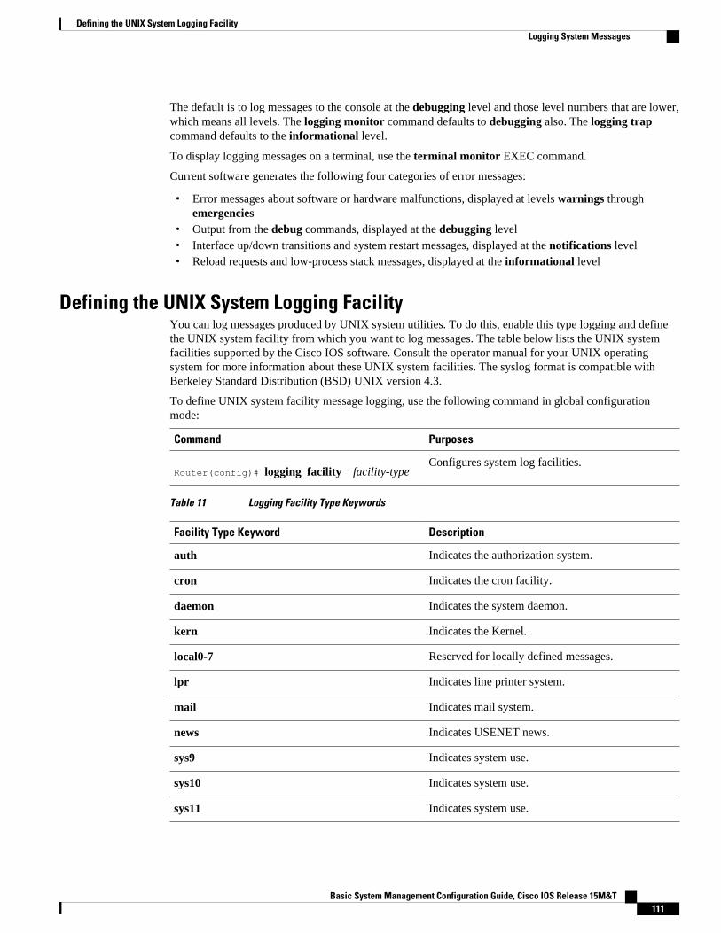
The default is to log messages to the console at the debugging level and those level numbers that are lower,which means all levels. The logging monitor command defaults to debugging also. The logging trapcommand defaults to the informational level.
To display logging messages on a terminal, use the terminal monitor EXEC command.
Current software generates the following four categories of error messages:
• Error messages about software or hardware malfunctions, displayed at levels warnings throughemergencies
• Output from the debug commands, displayed at the debugging level• Interface up/down transitions and system restart messages, displayed at the notifications level• Reload requests and low-process stack messages, displayed at the informational level
Defining the UNIX System Logging FacilityYou can log messages produced by UNIX system utilities. To do this, enable this type logging and definethe UNIX system facility from which you want to log messages. The table below lists the UNIX systemfacilities supported by the Cisco IOS software. Consult the operator manual for your UNIX operatingsystem for more information about these UNIX system facilities. The syslog format is compatible withBerkeley Standard Distribution (BSD) UNIX version 4.3.
To define UNIX system facility message logging, use the following command in global configurationmode:
Command Purposes
Router(config)# logging facility facility-typeConfigures system log facilities.
Table 11 Logging Facility Type Keywords
Facility Type Keyword Description
auth Indicates the authorization system.
cron Indicates the cron facility.
daemon Indicates the system daemon.
kern Indicates the Kernel.
local0-7 Reserved for locally defined messages.
lpr Indicates line printer system.
mail Indicates mail system.
news Indicates USENET news.
sys9 Indicates system use.
sys10 Indicates system use.
sys11 Indicates system use.
Defining the UNIX System Logging FacilityLogging System Messages
Basic System Management Configuration Guide, Cisco IOS Release 15M&T 111

Facility Type Keyword Description
sys12 Indicates system use.
sys13 Indicates system use.
sys14 Indicates system use.
syslog Indicates the system log.
user Indicates user process.
uucp Indicates UNIX-to-UNIX copy system.
Displaying Logging InformationTo display logging information, use the following commands in EXEC mode, as needed:
Command Purposes
Router# show loggingDisplays the state of syslog error and event logging,including host addresses, whether console loggingis enabled, and other logging statistics.
Router# show controllers vip slot-number logging
Displays the state of syslog error and event loggingof a VIP card, including host addresses, whetherconsole logging is enabled, and other loggingstatistics.
Router# show logging history Displays information in the syslog history tablesuch as the table size, the status of messages, andthe text of the messages stored in the table.
Logging Errors to a UNIX Syslog DaemonTo configure the syslog daemon on a 4.3 BSD UNIX system, include a line such as the following inthe /etc/syslog.conf file:
local7.debugging /usr/adm/logs/cisco.log
The debugging keyword specifies the syslog level; see Logging Errors to a UNIX Syslog Daemon, page112 for a general description of other keywords. The local7 keyword specifies the logging facility to beused; see Logging Errors to a UNIX Syslog Daemon, page 112 for a general description of otherkeywords.
The syslog daemon sends messages at this level or at a more severe level to the file specified in the nextfield. The file must already exist, and the syslog daemon must have permission to write to it.
Setting the Syslog Source AddressBy default, a syslog message contains the IP address of the interface it uses to leave the router. To set allsyslog messages to contain the same IP address, regardless of which interface they use, use the followingcommand in global configuration mode.
Displaying Logging Information Logging System Messages
Basic System Management Configuration Guide, Cisco IOS Release 15M&T112

Command Purposes
Router(config)# logging source-interface type number
Sets the syslog source address.
Using Field Diagnostics on Line CardsEach line card on the Cisco 12000 series routers can perform field diagnostic testing to isolate faultyhardware without disrupting normal operation of the system. However, performing field diagnostic testingon a line card does halt all activity on the line card for the duration of the testing. After successfulcompletion of the field diagnostic testing, the Cisco IOS software is automatically reloaded on the linecard.
Note The field diagnostic diag command must be executed from the Gigabit Route Processor (GRP) mainconsole port.
To perform field diagnostic testing on a line card, use the following command in privileged EXEC mode:
Command Purposes
Router# diag slot-number [previous | post | verbose | wait]
Specifies the line card on which you want toperform diagnostic testing.
Optionally, specifies that previous test results aredisplayed, that only extended power-on self-tests(POST) be performed, that the maximum messagesare displayed, or that the Cisco IOS software not bereloaded on the line card after successfulcompletion of the tests. The following prompt isdisplayed:
Running Diags will halt ALL activity on the requested slot. [confirm]
At the prompt, press Return to confirm that youwant to perform field diagnostic testing on thespecified line card, or type no to stop the testing.
To stop field diagnostic testing on a line card, use either of the following commands in privileged EXECmode:
Command Purpose
Router# diag slot-number halt
or
Router# no diag slot-number
Specifies the line card on which you want to stopdiagnostic testing.
Troubleshooting and Fault ManagementUsing Field Diagnostics on Line Cards
Basic System Management Configuration Guide, Cisco IOS Release 15M&T 113

Note When you stop the field diagnostic test, the line card remains down (that is, in an unbooted state). In mostcases, you stopped the testing because you need to remove the line card or replace the line card. If that isnot the case and you want to bring the line card back up (that is, online), you must use the microcodereload global configuration command or power cycle the line card.
Troubleshooting Specific Line CardsCisco IOS provides the execute-on command to allow you to issue Cisco IOS commands (such as showcommands) to a specific line card for monitoring and maintenance. For example, you could show whichCisco IOS image is loaded on the card in slot 3 of a Cisco 12012 Gigabit Switch Router (GSR) by issuingthe execute-on slot 3 show versioncommand. You can also use this command for troubleshooting cards inthe dial shelf of Cisco access servers.
Storing Line Card Crash InformationThis section explains how to enable storing of crash information for a line card and optionally specify thetype and amount of information stored. Technical support representatives need to be able to look at thecrash information from the line card to troubleshoot serious problems on the line card. The crashinformation contains all the line card memory information, including the main memory and transmit andreceive buffer information.
Caution Use the exception linecard global configuration command only when directed by a technical supportrepresentative, and only enable options that the technical support representative requests you to enable.
To enable and configure the crash information options for a line card, use the following command in globalconfiguration mode.
Command Purpose
Router(config)# exception linecard {all | slot slot-number} [corefile filename | main-memory size [k | m] | queue-ram size [k | m] | rx-buffer size [k | m] | sqe-register-rx | sqe-register-tx | tx-buffer size [k | m]]
Specifies the line card for which you want crashinformation when a line card resets. Optionally,specify the type and amount of memory to bestored.
Creating Core Dumps for System Exceptions“System exceptions” are any unexpected system shutdowns or reboots (most frequently caused by a systemfailure, commonly referred to as a “system crash”). When an exception occurs, it is sometimes useful toobtain a full copy of the memory image (called a core dump) to identify the cause of the unexpectedshutdown. Not all exception types will produce a core dump.
Core dumps are generally useful only to your technical support representative. The core dump file, which isa very large binary file, can be transferred to a Trivial File Transfer Protocol (TFTP), File Transfer Protocol
Troubleshooting and Fault Management Troubleshooting Specific Line Cards
Basic System Management Configuration Guide, Cisco IOS Release 15M&T114

(FTP), or Remote Copy Protocol (RCP) server, or (on limited platforms) saved to the flash disk, andsubsequently interpreted by technical personnel who have access to source code and detailed memorymaps.
Caution Use the exception commands only under the direction of a technical support representative. Creating a coredump while the router is functioning in a network can disrupt network operation.
• Specifying the Destination for the Core Dump File, page 115• Creating an Exception Memory Core Dump, page 118
Specifying the Destination for the Core Dump FileTo configure the router to generate a core dump, you must enable exception dumps and configure adestination for the core dump file, as described in the following sections:
• Using TFTP for Core Dumps, page 115• Using FTP for Core Dumps, page 116• Using rcp for Core Dumps, page 117• Using a Flash Disk for Core Dumps, page 118
Using TFTP for Core DumpsDue to a limitation of most TFTP applications, the router will dump only the first 16 MB of the core file.Therefore, if your router’s main memory is larger than 16 MB, do not use TFTP.
To configure a router for a core dump using TFTP, use the following commands in global configurationmode:
SUMMARY STEPS
1. exception protocol tftp
2. exception dump ip-address
3. exception core-file [filepath/]filename
DETAILED STEPS
Command or Action Purpose
Step 1 exception protocol tftp
Example:
(Optional) Explicitly specifies TFTP as the protocol to be used for routerexceptions (core dumps for unexpected system shutdowns).
Note Because TFTP is the default exception protocol, the exception protocol tftpcommand does not need to be used unless the protocol has been previouslychanged to ftp or rcp in your system’s configuration. To determine if theexception protocol has been changed, use the show running-configcommand in EXEC mode.
Specifying the Destination for the Core Dump FileUsing TFTP for Core Dumps
Basic System Management Configuration Guide, Cisco IOS Release 15M&T 115

Command or Action Purpose
Step 2 exception dump ip-address
Example:
Configures the router to dump a core file to the specified server if the routercrashes.
Step 3 exception core-file[filepath/]filename
Example:
(Optional) Specifies the name to be used for the core dump file. The file usuallymust pre-exist on the TFTP server, and be writable.
For example, the following command configures a router to send a core file to the server at the IP address172.17.92.2. As the exception protocol is not specified, the default protocol of TFTP will be used.
Router(config)# exception dump 172.17.92.2
The core dump is written to a file named "hostname -core" on the TFTP server, where hostname is thename of the route (in the example above, the file would be named Router-core). You can change the nameof the core file by adding the exception core-file filename configuration command.
Depending on the TFTP server application used, it may be necessary to create, on the TFTP server, theempty target file to which the router can write the core. Also, make sure there is enough memory on yourTFTP server to hold the complete core dump.
Using FTP for Core DumpsTo configure the router for a core dump using FTP, use the following commands in global configurationmode:
SUMMARY STEPS
1. Router(config)# ip ftp username username
2. Router(config)# ip ftp password[type] password
3. Router(config)# exception protocol ftp
4. Router(config)# exception dump ip-address
5. Router(config)# exception core-file filename
DETAILED STEPS
Command or Action Purpose
Step 1 Router(config)# ip ftp username username (Optional) Configures the user name for FTP connections.
Step 2 Router(config)# ip ftp password[type]password
(Optional) Specifies the password to be used for FTP connections.
Step 3 Router(config)# exception protocol ftp Specifies that FTP should be used for core dump file transfers.
Troubleshooting and Fault Management Using FTP for Core Dumps
Basic System Management Configuration Guide, Cisco IOS Release 15M&T116
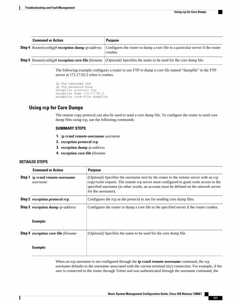
Command or Action Purpose
Step 4 Router(config)# exception dump ip-address Configures the router to dump a core file to a particular server if the routercrashes.
Step 5 Router(config)# exception core-file filename (Optional) Specifies the name to be used for the core dump file.
The following example configures a router to use FTP to dump a core file named “dumpfile” to the FTPserver at 172.17.92.2 when it crashes.
ip ftp username redip ftp password blueexception protocol ftpexception dump 172.17.92.2exception core-file dumpfile
Using rcp for Core DumpsThe remote copy protocol can also be used to send a core dump file. To configure the router to send coredump files using rcp, use the following commands:
SUMMARY STEPS
1. ip rcmd remote-username username
2. exception protocol rcp3. exception dump ip-address
4. exception core-file filename
DETAILED STEPS
Command or Action Purpose
Step 1 ip rcmd remote-usernameusername
(Optional) Specifies the username sent by the router to the remote server with an rcpcopy/write request. The remote rcp server must configured to grant write access to thespecified username (in other words, an account must be defined on the network serverfor the username).
Step 2 exception protocol rcp Configures the rcp as the protocol to use for sending core dump files.
Step 3 exception dump ip-address
Example:
Configures the router to dump a core file to the specified server if the router crashes.
Step 4 exception core-file filename
Example:
(Optional) Specifies the name to be used for the core dump file.
When an rcp username is not configured through the ip rcmd remote-username command, the rcpusername defaults to the username associated with the current terminal (tty) connection. For example, if theuser is connected to the router through Telnet and was authenticated through the username command, the
Troubleshooting and Fault ManagementUsing rcp for Core Dumps
Basic System Management Configuration Guide, Cisco IOS Release 15M&T 117

router software sends the Telnet username as the rcp username. If the terminal username is not available,the router hostname will be used as the rcp username.
Using a Flash Disk for Core DumpsSome router platforms support the Flash disk as an alternative to the linear Flash memory or PCMCIAFlash card. The large storage capacity of these Flash disks makes them good candidates for another meansof capturing a core dump. To configure a router for a core dump using a Flash disk, use the followingcommand in global configuration mode:
Command Purpose
Router(config)# exception flash [procmem |iomem | all] device-name[:partition-number] [erase | no_erase]
Configures the router for a core dump using a flashdisk.
Router(config)# exception core-file filename (Optional) Specifies the name to be used for thecore dump file.
The show flash all EXEC command will list the devices you can use for the exception flash command.
Creating an Exception Memory Core DumpTo cause the router to create a core dump and reboot when certain memory size parameters are violatedduring the debugging process, use the following commands in global configuration mode:
As a debugging procedure, you can cause the router to create a core dump and reboot when certain memorysize parameters are violated. The following exception memory commands are used to trigger a core dump:
Command Purpose
Router(config)# exception memory minimum
bytes
Triggers a core dump and system reload when theamount of free memory falls below the specifiednumber of bytes.
• Do not specify too low a memory value, as therouter needs some amount of free memory toprovide the core dump.
• If you enter a size that is greater than the freememory (and the exception dump commandhas been configured), a core dump and routerreload is generated after 60 seconds.
Creating an Exception Memory Core Dump Using a Flash Disk for Core Dumps
Basic System Management Configuration Guide, Cisco IOS Release 15M&T118
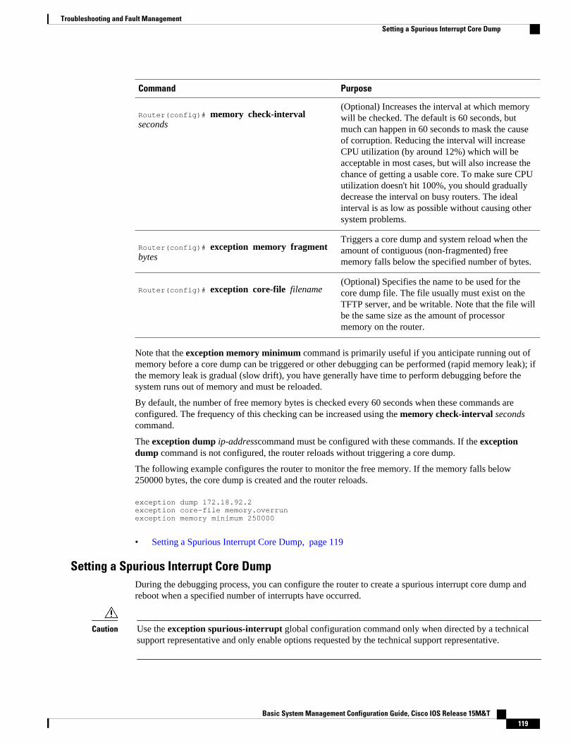
Command Purpose
Router(config)# memory check-interval seconds
(Optional) Increases the interval at which memorywill be checked. The default is 60 seconds, butmuch can happen in 60 seconds to mask the causeof corruption. Reducing the interval will increaseCPU utilization (by around 12%) which will beacceptable in most cases, but will also increase thechance of getting a usable core. To make sure CPUutilization doesn't hit 100%, you should graduallydecrease the interval on busy routers. The idealinterval is as low as possible without causing othersystem problems.
Router(config)# exception memory fragment bytes
Triggers a core dump and system reload when theamount of contiguous (non-fragmented) freememory falls below the specified number of bytes.
Router(config)# exception core-file filename (Optional) Specifies the name to be used for thecore dump file. The file usually must exist on theTFTP server, and be writable. Note that the file willbe the same size as the amount of processormemory on the router.
Note that the exception memory minimum command is primarily useful if you anticipate running out ofmemory before a core dump can be triggered or other debugging can be performed (rapid memory leak); ifthe memory leak is gradual (slow drift), you have generally have time to perform debugging before thesystem runs out of memory and must be reloaded.
By default, the number of free memory bytes is checked every 60 seconds when these commands areconfigured. The frequency of this checking can be increased using the memory check-interval secondscommand.
The exception dump ip-addresscommand must be configured with these commands. If the exceptiondump command is not configured, the router reloads without triggering a core dump.
The following example configures the router to monitor the free memory. If the memory falls below250000 bytes, the core dump is created and the router reloads.
exception dump 172.18.92.2exception core-file memory.overrunexception memory minimum 250000
• Setting a Spurious Interrupt Core Dump, page 119
Setting a Spurious Interrupt Core DumpDuring the debugging process, you can configure the router to create a spurious interrupt core dump andreboot when a specified number of interrupts have occurred.
Caution Use the exception spurious-interrupt global configuration command only when directed by a technicalsupport representative and only enable options requested by the technical support representative.
Troubleshooting and Fault ManagementSetting a Spurious Interrupt Core Dump
Basic System Management Configuration Guide, Cisco IOS Release 15M&T 119

To enable and configure the crash information for spurious interrupts, use the following commands inglobal configuration mode:
Command Purpose
Router(config)# exception spurious-interrupt number
Sets the maximum number of spurious interrupts toinclude in the core dump before reloading.
Router(config)# exception dump ip-address
or
Router(config)# exception flash
Specifies the destination for the core dump file.
The following example configures a router to create a core dump with a limit of two spurious interrupts:
exception spurious-interrupt 2 exception dump 209.165.200.225
Enabling Debug OperationsYour router includes hardware and software to aid in troubleshooting internal problems and problems withother hosts on the network. The debug privileged EXEC mode commands start the console display ofseveral classes of network events. The following commands describe in general the system debug messagefeature. Refer to the Cisco IOS Debug Command Reference for all information regarding debugcommands. Also refer to the Internetwork Troubleshooting Guide publication for additional information.
To enable debugging operations, use the following commands:
Command Purposes
Router# show debugging Displays the state of each debugging option.
Router# debug ?Displays a list and brief description of all the debugcommand options.
Router# debug commandBegins message logging for the specified debugcommand.
Router# no debug commandTurns message logging off for the specified debugcommand.
Caution The system gives high priority to debugging output. For this reason, debugging commands should be turnedon only for troubleshooting specific problems or during troubleshooting sessions with technical supportpersonnel. Excessive debugging output can render the system inoperable.
You can configure time-stamping of system debug messages. Time-stamping enhances real-timedebugging by providing the relative timing of logged events. This information is especially useful when
Troubleshooting and Fault Management Enabling Debug Operations
Basic System Management Configuration Guide, Cisco IOS Release 15M&T120

customers send debugging output to your technical support personnel for assistance. To enable time-stamping of system debug messages, use either of the following commands in global configuration mode:
Command Purposes
Router(config)# service timestamps debug uptime
or
Router(config)# service timestamps debug datetime [msec] [localtime] [show-timezone]
Enables time-stamping of system debug messages.
Normally, the messages are displayed only on the console terminal. Refer to the section “Setting the SyslogDestination, page 108” earlier in this chapter to change the output device.
Enabling Conditionally Triggered DebuggingWhen the Conditionally Triggered Debugging feature is enabled, the router generates debugging messagesfor packets entering or leaving the router on a specified interface; the router will not generate debuggingoutput for packets entering or leaving through a different interface. You can specify the interfacesexplicitly. For example, you may only want to see debugging messages for one interface or subinterface.You can also turn on debugging for all interfaces that meet specified condition. This feature is useful ondial access servers, which have a large number of ports.
Normally, the router will generate debugging messages for every interface, resulting in a large number ofmessages. The large number of messages consumes system resources, and can affect your ability to find thespecific information you need. By limiting the number of debugging messages, you can receive messagesrelated to only the ports you wish to troubleshoot.
Conditionally Triggered Debugging controls the output from the following protocol-specific debugcommands:
• debug aaa {accounting | authorization | authentication}• debug dialer {events | packets}• debug isdn {q921 | q931}• debug modem {oob | trace}• debug ppp {all | authentication | chap | error | negotiation | multilink events | packet}
Although this feature limits the output of the commands listed, it does not automatically enable thegeneration of debugging output from these commands. Debugging messages are generated only when theprotocol-specific debug command is enabled. The debug command output is controlled through twoprocesses:
• The protocol-specific debug commands specify which protocols are being debugged. For example, thedebug dialer events command generates debugging output related to dialer events.
• The debug condition commands limit these debugging messages to those related to a particularinterface. For example, the debug condition username bob command generates debugging outputonly for interfaces with packets that specify a username of bob.
To configure Conditionally Triggered Debugging, perform the tasks described in the following sections:
Troubleshooting and Fault ManagementEnabling Conditionally Triggered Debugging
Basic System Management Configuration Guide, Cisco IOS Release 15M&T 121

• Enabling Protocol-Specific debug Commands, page 122• Enabling Conditional Debugging Commands, page 122• Specifying Multiple Debugging Conditions, page 124• Conditionally Triggered Debugging Configuration Examples, page 124
Enabling Protocol-Specific debug CommandsIn order to generate any debugging output, the protocol-specific debug command for the desired outputmust be enabled. Use the show debugging command to determine which types of debugging are enabled.To display the current debug conditions, use the show debug condition command. To enable the desiredprotocol-specific debug commands, use the following commands in privileged EXEC mode:
Command Purpose
Router# show debuggingDetermines which types of debugging are enabled.
Router# show debug condition [condition-id]Displays the current debug conditions.
Router# debug protocolEnables the desired debugging commands.
Router# no debug protocolDisables the debugging commands that are notdesired.
If you do not want output, disable all the protocol-specific debug commands.
Enabling Conditional Debugging CommandsIf no debug condition commands are enabled, all debugging output, regardless of the interface, will bedisplayed for the enabled protocol-specific debug commands.
The first debug condition command you enter enables conditional debugging. The router will display onlymessages for interfaces that meet one of the specified conditions. If multiple conditions are specified, theinterface must meet at least one of the conditions in order for messages to be displayed.
To enable messages for interfaces specified explicitly or for interfaces that meet certain conditions, performthe tasks described in the following sections:
• Displaying Messages for One Interface, page 122• Displaying Messages for Multiple Interfaces, page 123• Limiting the Number of Messages Based on Conditions, page 123
Displaying Messages for One InterfaceTo disable debugging messages for all interfaces except one, use the following command in privilegedEXEC mode:
Command Purpose
Router# debug condition interface interfaceEnables debugging output for only the specifiedinterface.
To reenable debugging output for all interfaces, use the no debug interfacecommand.
Enabling Protocol-Specific debug Commands Displaying Messages for One Interface
Basic System Management Configuration Guide, Cisco IOS Release 15M&T122

Displaying Messages for Multiple InterfacesTo enable debugging messages for multiple interfaces, use the following commands in privileged EXECmode:
SUMMARY STEPS
1. Router# debug condition interface interface
2. Router# debug condition interface interface
DETAILED STEPS
Command or Action Purpose
Step 1 Router# debug condition interface interface Enables debugging output for only the specified interface
Step 2 Router# debug condition interface interface Enable debugging messages for additional interfaces. Repeat this task untildebugging messages are enabled for all desired interfaces.
If you specify more than one interface by entering this command multiple times, debugging output will bedisplayed for all of the specified interfaces. To turn off debugging on a particular interface, use the nodebug interface command. If you use the no debug interface all command or remove the last debuginterface command, debugging output will be reenabled for all interfaces.
Limiting the Number of Messages Based on ConditionsThe router can monitor interfaces to learn if any packets contain the specified value for one of thefollowing conditions:
• username• calling party number• called party number
If you enter a condition, such as calling number, debug output will be stopped for all interfaces. The routerwill then monitor every interface to learn if a packet with the specified calling party number is sent orreceived on any interfaces. If the condition is met on an interface or subinterface, debug command outputwill be displayed for that interface. The debugging output for an interface is “triggered” when the conditionhas been met. The debugging output continues to be disabled for the other interfaces. If, at some later time,the condition is met for another interface, the debug output also will become enabled for that interface.
Once debugging output has been triggered on an interface, the output will continue until the interface goesdown. However, the session for that interface might change, resulting in a new username, called partynumber, or calling party number. Use the no debug interface command to reset the debug triggermechanism for a particular interface. The debugging output for that interface will be disabled until theinterface meets one of the specified conditions.
To limit the number of debugging messages based on a specified condition, use the following command inprivileged EXEC mode:
Troubleshooting and Fault ManagementDisplaying Messages for Multiple Interfaces
Basic System Management Configuration Guide, Cisco IOS Release 15M&T 123

Command Purpose
Router# debug condition {username username | called dial-string | caller dial-string}
Enables conditional debugging. The router willdisplay only messages for interfaces that meet thiscondition.
To reenable the debugging output for all interfaces, enter the no debug condition all command.
Specifying Multiple Debugging ConditionsTo limit the number of debugging messages based on more than one condition, use the followingcommands in privileged EXEC mode:
SUMMARY STEPS
1. Router# debug condition{username username | called dial-string | caller dial-string}
2. Router# debug condition{username username | called dial-string | caller dial-string}
DETAILED STEPS
Command or Action Purpose
Step 1 Router# debug condition{username username | called dial-string |caller dial-string}
Enables conditional debugging, and specifies thefirst condition.
Step 2 Router# debug condition{username username | called dial-string |caller dial-string}
Specifies the second condition. Repeat this taskuntil all conditions are specified.
If you enter multiple debug condition commands, debugging output will be generated if an interface meetsat least one of the conditions. If you remove one of the conditions using the no debug condition command,interfaces that meet only that condition no longer will produce debugging output. However, interfaces thatmeet a condition other than the removed condition will continue to generate output. Only if no activeconditions are met for an interface will the output for that interface be disabled.
Conditionally Triggered Debugging Configuration ExamplesIn this example, four conditions have been set by the following commands:
• debug condition interface serial 0• debug condition interface serial 1• debug condition interface virtual-template 1• debug condition username fred
The first three conditions have been met by one interface. The fourth condition has not yet been met:
Router# show debug conditionCondition 1: interface Se0 (1 flags triggered) Flags: Se0Condition 2: interface Se1 (1 flags triggered) Flags: Se1Condition 3: interface Vt1 (1 flags triggered) Flags: Vt1Condition 4: username fred (0 flags triggered)
When any debug condition command is entered, debugging messages for conditional debugging areenabled. The following debugging messages show conditions being met on different interfaces as the serial
Specifying Multiple Debugging Conditions Limiting the Number of Messages Based on Conditions
Basic System Management Configuration Guide, Cisco IOS Release 15M&T124

0 and serial 1 interfaces come up. For example, the second line of output indicates that serial interface 0meets the username fred condition.
*Mar 1 00:04:41.647: %LINK-3-UPDOWN: Interface Serial0, changed state to up*Mar 1 00:04:41.715: Se0 Debug: Condition 4, username fred triggered, count 2*Mar 1 00:04:42.963: %LINEPROTO-5-UPDOWN: Line protocol on Interface Serial0, changed state to up*Mar 1 00:04:43.271: Vi1 Debug: Condition 3, interface Vt1 triggered, count 1*Mar 1 00:04:43.271: %LINK-3-UPDOWN: Interface Virtual-Access1, changed state to up*Mar 1 00:04:43.279: Vi1 Debug: Condition 4, username fred triggered, count 2*Mar 1 00:04:43.283: Vi1 Debug: Condition 1, interface Se0 triggered, count 3*Mar 1 00:04:44.039: %IP-4-DUPADDR: Duplicate address 172.27.32.114 on Ethernet 0, sourced by 00e0.1e3e.2d41*Mar 1 00:04:44.283: %LINEPROTO-5-UPDOWN: Line protocol on Interface Virtual-Access1, changed state to up*Mar 1 00:04:54.667: %LINK-3-UPDOWN: Interface Serial1, changed state to up*Mar 1 00:04:54.731: Se1 Debug: Condition 4, username fred triggered, count 2*Mar 1 00:04:54.735: Vi1 Debug: Condition 2, interface Se1 triggered, count 4*Mar 1 00:04:55.735: %LINEPROTO-5-UPDOWN: Line protocol on Interface Serial1, changed state to up
After a period of time, the show debug condition command displays the revised list of conditions:
Router# show debug conditionCondition 1: interface Se0 (2 flags triggered) Flags: Se0 Vi1Condition 2: interface Se1 (2 flags triggered) Flags: Se1 Vi1Condition 3: interface Vt1 (2 flags triggered) Flags: Vt1 Vi1Condition 4: username fred (3 flags triggered) Flags: Se0 Vi1 Se1
Next, the serial 1 and serial 0 interfaces go down. When an interface goes down, conditions for thatinterface are cleared.
*Mar 1 00:05:51.443: %LINK-3-UPDOWN: Interface Serial1, changed state to down*Mar 1 00:05:51.471: Se1 Debug: Condition 4, username fred cleared, count 1*Mar 1 00:05:51.479: Vi1 Debug: Condition 2, interface Se1 cleared, count 3*Mar 1 00:05:52.443: %LINEPROTO-5-UPDOWN: Line protocol on Interface Serial1, changed state to down*Mar 1 00:05:56.859: %LINK-3-UPDOWN: Interface Serial0, changed state to down*Mar 1 00:05:56.887: Se0 Debug: Condition 4, username fred cleared, count 1*Mar 1 00:05:56.895: Vi1 Debug: Condition 1, interface Se0 cleared, count 2*Mar 1 00:05:56.899: Vi1 Debug: Condition 3, interface Vt1 cleared, count 1*Mar 1 00:05:56.899: Vi1 Debug: Condition 4, username fred cleared, count 0*Mar 1 00:05:56.903: %LINK-3-UPDOWN: Interface Virtual-Access1, changed state to down*Mar 1 00:05:57.907: %LINEPROTO-5-UPDOWN: Line protocol on Interface Serial0, changed state to down*Mar 1 00:05:57.907: %LINEPROTO-5-UPDOWN: Line protocol on Interface Virtual-Access1, changed state to down
The final show debug condition output is the same as the output before the interfaces came up:
Router# show debug conditionCondition 1: interface Se0 (1 flags triggered) Flags: Se0Condition 2: interface Se1 (1 flags triggered) Flags: Se1Condition 3: interface Vt1 (1 flags triggered) Flags: Vt1Condition 4: username fred (0 flags triggered)
Using the Environmental MonitorSome routers and access servers have an environmental monitor that monitors the physical condition of therouter. If a measurement exceeds acceptable margins, a warning message is printed to the system console.
Troubleshooting and Fault ManagementUsing the Environmental Monitor
Basic System Management Configuration Guide, Cisco IOS Release 15M&T 125

The system software collects measurements once every 60 seconds, but warnings for a given test point areprinted at most once every 4 hours. If the temperature measurements are out of specification more than theshutdown, the software shuts the router down (the fan will remain on). The router must be manually turnedoff and on after such a shutdown. You can query the environmental monitor using the show environmentcommand at any time to determine whether a measurement is out of tolerance. Refer to the Cisco IOSSystem Error Messages publication for a description of environmental monitor warning messages.
On routers with an environmental monitor, if the software detects that any of its temperature test pointshave exceeded maximum margins, it performs the following steps:
1 Saves the last measured values from each of the six test points to internal nonvolatile memory.2 Interrupts the system software and causes a shutdown message to be printed on the system console.3 Shuts off the power supplies after a few milliseconds of delay.
The system displays the following message if temperatures exceed maximum margins, along with amessage indicating the reason for the shutdown:
Router#%ENVM-1-SHUTDOWN: Environmental Monitor initiated shutdown%ENVM-2-TEMP: Inlet temperature has reached SHUTDOWN level at 64(C)
Refer to the hardware installation and maintenance publication for your router for more information aboutenvironmental specifications.
Cisco and the Cisco logo are trademarks or registered trademarks of Cisco and/or its affiliates in the U.S.and other countries. To view a list of Cisco trademarks, go to this URL: www.cisco.com/go/trademarks.Third-party trademarks mentioned are the property of their respective owners. The use of the word partnerdoes not imply a partnership relationship between Cisco and any other company. (1110R)
Any Internet Protocol (IP) addresses and phone numbers used in this document are not intended to beactual addresses and phone numbers. Any examples, command display output, network topology diagrams,and other figures included in the document are shown for illustrative purposes only. Any use of actual IPaddresses or phone numbers in illustrative content is unintentional and coincidental.
Troubleshooting and Fault Management
Basic System Management Configuration Guide, Cisco IOS Release 15M&T126
Configuring the XML Interface to SyslogMessages
The XML Interface to Syslog Messages features provides command-line interface (CLI) commands forenabling syslog messages to be sent in an Extensible Markup Language (XML) format. Logs in astandardized XML format can be more readily used in external customized monitoring tools.
• Finding Feature Information, page 127• Information About the XML Interface to Syslog Messages Feature, page 127• How to Configure XML Formatting of Syslog Messages, page 131• Configuration Examples for XML Formatting of Syslog Messages, page 132• Additional References, page 133• Feature Information for XML Interface to Syslog Messages, page 134• Glossary, page 135
Finding Feature InformationYour software release may not support all the features documented in this module. For the latest caveatsand feature information, see Bug Search Tool and the release notes for your platform and software release.To find information about the features documented in this module, and to see a list of the releases in whicheach feature is supported, see the feature information table at the end of this module.
Use Cisco Feature Navigator to find information about platform support and Cisco software image support.To access Cisco Feature Navigator, go to www.cisco.com/go/cfn. An account on Cisco.com is not required.
Information About the XML Interface to Syslog MessagesFeature
• Cisco IOS System Message Logging, page 127• XML-Formatted System Message Logging, page 128• System Logging Message Formatting, page 128
Cisco IOS System Message LoggingThe Cisco IOS system message logging (syslog) process allows the system to report and save importanterror and notifications messages, either locally or to a remote logging server. These syslog messages
Basic System Management Configuration Guide, Cisco IOS Release 15M&T 127

include messages in a standardized format (often called system error messages) and output from debugcommands. These messages are generated during network operation to assist users and Cisco TACengineers with identifying the type and severity of a problem, or to aid users in monitoring router activity.Syslog messages can be sent to the console, a monitor (TTY and Telnet connections), the system buffer, orto remote hosts.
Note The system message logging process in Cisco IOS software is abbreviated as "syslog". The messagesgenerated by this process are called "syslog messages". However, syslog messages are also referred to inCisco IOS documenation as "system error messages" or "SEMs". Note that syslog messages are notrestricted to error conditions, and can reflect purely informational messages.
XML-Formatted System Message LoggingXML, a derivative of SGML, provides a representation scheme to structuralize consistently formatted datasuch as that found in syslog messages.
The XML Interface to Syslog Messages features provides CLI commands for enabling syslog messages tobe sent in an XML format. Logs in a standardized XML format can be more readily used in externalcustomized monitoring tools. Within the Cisco IOS software, a closed set of meaningful XML tags aredefined and, when enabled, applied to the syslog messages sent to the console, monitor, buffer, or to remotehosts.
Two system logging formats exist in Cisco IOS software: the standard logging format and the XMLlogging format. This means that you can specify that the standard syslog messages be sent to one remotehost while the XML-formatted syslog messages are sent to another host. Similarly, if logging messages aresent to the system buffer, the XML logging buffer is separate from the standard logging buffer, and you canhave the standard and XML logging buffers running at the same time.
The XML logging process is dependant on the standard logging process. In most cases, settings for thestandard logging process carry over to the XML logging process. For example, the severity level for thelogging buffered xml command is determined by the level set for the standard logging buffered command(or, if not set, by the default severity level for the standard buffer). Similarly, the default size of the XMLlogging buffer is the same as the standard logging buffer’s default (the default buffer size varies byplatform).
System Logging Message FormattingSystem logging messages take the following format:
%<facility>-<severity>-<mnemonic>: <message-text>
For example:
%LINK-5-CHANGED: Interface Serial3/3, changed state to administratively down
Usually, these messages are proceeded by additional text, such as the timestamp and message sequencenumber:
<sequence-number>: <date or system-up-time> <time>:%<facility>-<severity>-<mnemonic>: <message-text>
XML-Formatted System Message Logging Information About the XML Interface to Syslog Messages Feature
Basic System Management Configuration Guide, Cisco IOS Release 15M&T128
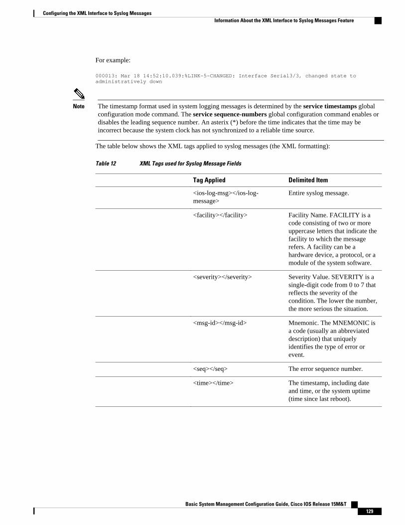
For example:
000013: Mar 18 14:52:10.039:%LINK-5-CHANGED: Interface Serial3/3, changed state to administratively down
Note The timestamp format used in system logging messages is determined by the service timestamps globalconfiguration mode command. The service sequence-numbers global configuration command enables ordisables the leading sequence number. An asterix (*) before the time indicates that the time may beincorrect because the system clock has not synchronized to a reliable time source.
The table below shows the XML tags applied to syslog messages (the XML formatting):
Table 12 XML Tags used for Syslog Message Fields
Tag Applied Delimited Item
<ios-log-msg></ios-log-message>
Entire syslog message.
<facility></facility> Facility Name. FACILITY is acode consisting of two or moreuppercase letters that indicate thefacility to which the messagerefers. A facility can be ahardware device, a protocol, or amodule of the system software.
<severity></severity> Severity Value. SEVERITY is asingle-digit code from 0 to 7 thatreflects the severity of thecondition. The lower the number,the more serious the situation.
<msg-id></msg-id> Mnemonic. The MNEMONIC isa code (usually an abbreviateddescription) that uniquelyidentifies the type of error orevent.
<seq></seq> The error sequence number.
<time></time> The timestamp, including dateand time, or the system uptime(time since last reboot).
Configuring the XML Interface to Syslog MessagesInformation About the XML Interface to Syslog Messages Feature
Basic System Management Configuration Guide, Cisco IOS Release 15M&T 129

Tag Applied Delimited Item
<args></args> The variables within the messagetext. The full "human readable"text of the message is not retainedin XML. Only the variables areextracted and formatted.
The variables within a systemerror message are identified withbrackets ( [chars] , [hex] , [int] ,and so on) in Cisco IOSdocumentation.
For example:
%LINK-5-CHANGED: :Interface [chars], changed state to[chars]
For the complete text of syslogmessages, see the Cisco IOSSystem Error Messagesdocument, available onCisco.com.
All these XML tags addsignificant overhead to amessage. In case the messagelength exceeds the limit of IOSmessage logging, the "<args>...</args>" part will be replaced with"<args-warning>*** LOGOVERRUN ***</args-warning>"
<arg id="x"></arg> A specific argument. "x" is asequential variable I.D. number,starting with zero.
The following example shows a syslog message in standard format, followed by the same message withXML formatting applied:
Standard Syslog Message Format
000013: *Oct 11 14:52:10.039: %SYS-5-CONFIG_I: Configured from console by vty0 (172.19.208.14)
XML Syslog Message Format
<ios-log-msg><facility>SYS</facility><severity>5</severity><msg-id>CONFIG_I</msg-id><seq>000013</seq><time>*Oct 11 14:52:10.039</time><args><arg id="0">console</arg><arg id="1">vty0 (172.19.208.14)</arg></args></ios-log-msg>
Configuring the XML Interface to Syslog Messages Information About the XML Interface to Syslog Messages Feature
Basic System Management Configuration Guide, Cisco IOS Release 15M&T130

Note System logging messages include debugging messages when debugging is enabled on the router andlogging is configured to record severity level 7 messages. However, debugging messages do not use thesystem logging message format. XML formatting will not, therefore, be applied to these messages.
How to Configure XML Formatting of Syslog MessagesEnabling logging in an XML format consists of simply using the appropriate logging command to indicatewhere syslog messages should be sent, followed by the xml keyword. Standard system message logging isenabled by default, but XML formatting of these messages is disabled by default.
As mentioned previously, the XML-formatted logging process is separate than (but dependant on) thestandard logging process, so you can configure XML-formatted logging in addition to standard logging ifthe destination is a remote host or the system buffer.
To enable XML formatting for syslog messages, use one of the following commands in globalconfiguration mode:
• logging console xml• logging monitor xml• logging buffered xml• logging host {ip-address | host-name} xml
To view the status of logging and the contents of the XML logging buffer, use the show logging xmlcommand in EXEC mode. To clear the contents of the XML logging buffer, use the clear logging xmlcommand in EXEC mode.
SUMMARY STEPS
1. logging console xml [severity-level]
2. logging monitor xml [severity-level]
3. logging buffered xml [xml-buffer-size]
4. logging host {ip-address | host-name} xml
DETAILED STEPS
Command or Action Purpose
Step 1 logging console xml [severity-level]
Example:
Router(config)# logging console xml informational
Enables system message logging to the console connections in XML format.
Messages at or numerically below the severity level will be logged. The default severitylevel varies by platform, but is generally level 7 ("debugging"), meaning that messagesat all severity levels (0 through 7) are logged.
Configuring the XML Interface to Syslog MessagesHow to Configure XML Formatting of Syslog Messages
Basic System Management Configuration Guide, Cisco IOS Release 15M&T 131

Command or Action Purpose
Step 2 logging monitor xml [severity-level]
Example:
Router(config)# logging monitor xml 6
Enables system message logging to the monitor connections (all available TTY orTelnet connections) in XML format.
Messages at or numerically below the severity level will be logged. The default severitylevel varies by platform, but is generally level 7 ("debugging"), meaning that messagesat all severity levels (0 through 7) are logged.
Note that the display of logging messages is often disabled by default, meaning thatmessages will not be displayed when you log into the terminal until you issue theterminal monitor EXEC mode command.
Step 3 logging buffered xml [xml-buffer-size]
Example:
Router(config)# logging buffered xml 14336
Enables system message logging to the system buffer in XML format.
The severity level for logged messages is determined by the setting of the loggingbuffered command. If the logging buffered command has not been used, the defaultseverity level for that command is used. The default severity level varies by platform,but is generally level 7 ("debugging"), meaning that messages at all severity levels (0through 7) are logged. For more information on severity levels, see the documentationof the logging buffered command.
The default XML logging buffer size varies by platform. (The size of the XML loggingbuffer is the same as the standard logging buffer’s default.) The valid range for theXML buffer size is 4096 to 2147483647 bytes (4 Kilobytes to 2 Gigabytes).
Step 4 logging host {ip-address | host-name} xml
Example:
Router(config)# logging host 209.165.202.132 xml
Example:
Router(config)# logging host 209.165.201.20 xml
Enables system message logging in XML format to the specified host.
By issuing this command more than once, you build a list of syslog servers that receivelogging messages.
Note To send standard logging output to one host and XML-formatted logging outputto another host, you must specify a different IP address (or host name) in thelogging host (standard) command.
The default severity level varies by platform, but is generally level 7 ("debugging"),meaning that messages at severity levels 0 through 7 are logged. To specify the severitylevel for logging to all remote hosts, use the logging trap command.
Configuration Examples for XML Formatting of SyslogMessages
In the following example, logging is enabled and then logging to the standard buffer and to the XML bufferis enabled. The last two show logging commands compare the difference between the standard syslogbuffer and the XML syslog buffer.
Router# show loggingSyslog logging: disabled (10 messages dropped, 5 messages rate-limited, 6 flush) Console logging: disabled Monitor logging: disabled Buffer logging: disabled, xml disabled Logging Exception size (8192 bytes)
Configuring the XML Interface to Syslog Messages Configuration Examples for XML Formatting of Syslog Messages
Basic System Management Configuration Guide, Cisco IOS Release 15M&T132

Count and timestamp logging messages: disabled Trap logging: level informational, 31 message lines loggedRouter# config terminalEnter configuration commands, one per line. End with CNTL/Z.Router(config)# logging onRouter(config)# logging buffered Router(config)# endRouter# show loggingSyslog logging: enabled (10 messages dropped, 5 messages rate-limited, 6 flushed) Console logging: disabled Monitor logging: disabled Buffer logging: level debugging, 1 messages logged, xml disabled Logging Exception size (8192 bytes) Count and timestamp logging messages: disabled Trap logging: level informational, 32 message lines logged Log Buffer (8192 bytes):1w0d: %SYS-5-CONFIG_I: Configured from console by consoleRouter# configure terminal Enter configuration commands, one per line. End with CNTL/Z.Router(config)# logging buffered xmlRouter(config)# endRouter# show loggingSyslog logging: enabled (10 messages dropped, 5 messages rate-limited, 6 flushes, 0 overruns, xml enabled) Console logging: disabled Monitor logging: disabled Buffer logging: level debugging, 2 messages logged, xml enabled (1 messages logged) Logging Exception size (8192 bytes) Count and timestamp logging messages: disabled Trap logging: level informational, 33 message lines logged Log Buffer (8192 bytes):1w0d: %SYS-5-CONFIG_I: Configured from console by console1w0d: %SYS-5-CONFIG_I: Configured from console by consoleRouter# show logging xml<syslog-logging status="enabled" msg-dropped="10" msg-rate-limited="5" flushes="6" overruns="0"><xml>enabled</xml></syslog-logging> <console-logging>disabled</console-logging> <monitor-logging>disabled</monitor-logging> <buffer-logging level="debugging" messages-logged="2"><xml messages-logged="1">enabled</xml></buffer-logging> <logging-exception size="8192 bytes"></logging-exception> <count-and-timestamp-logging status="disabled"></count-and-timestamp-logging> <trap-logging level="informational" messages-lines-logged="33"></trap-logging> <log-xml-buffer size="8192 bytes"></log-xml-buffer><ios-log-msg><facility>SYS</facility><severity>5</severity><msg-id>CONFIG_I</msg-id><time>1w0d</time><args><arg id="0">console</arg><arg id="1">console</arg></args></ios-log-msg>
Additional ReferencesRelated Documents
Related Topic Document Title
System message logging Troubleshooting and Fault Management module
Debug-level system messages Cisco IOS Debug Command Reference
Configuring the XML Interface to Syslog MessagesAdditional References
Basic System Management Configuration Guide, Cisco IOS Release 15M&T 133

Standards
XML is not currently an Internet Standard. The XML 1.0 Recommendation ("Extensible Markup Language(XML) 1.0 (Second Edition)") is defined at http://www.w3.org/TR/. See also RFC 3076.
MIBs
MIB MIBs Link
-- To locate and download MIBs for selectedplatforms, Cisco software releases, and feature sets,use Cisco MIB Locator found at the followingURL:
http://www.cisco.com/go/mibs
RFCs
RFCs1 Title
RFC 3470 "Guidelines for the Use of Extensible MarkupLanguage (XML) within IETF Protocols" (Status:BEST CURRENT PRACTICE)
Technical Assistance
Description Link
The Cisco Support and Documentation websiteprovides online resources to downloaddocumentation, software, and tools. Use theseresources to install and configure the software andto troubleshoot and resolve technical issues withCisco products and technologies. Access to mosttools on the Cisco Support and Documentationwebsite requires a Cisco.com user ID andpassword.
http://www.cisco.com/cisco/web/support/index.html
System Error Message Decoder tool
For help with researching and resolving your CiscoIOS error messages, try the Cisco IOS ErrorMessage Decoder tool. This tool is made availableby the Cisco Technical Assistance Center (TAC)for registered Cisco.com users.
http://www.cisco.com/cgi-bin/Support/Errordecoder/home.pl
Feature Information for XML Interface to Syslog MessagesThe following table provides release information about the feature or features described in this module.This table lists only the software release that introduced support for a given feature in a given software
1 Not all supported RFCs are listed.
Configuring the XML Interface to Syslog Messages Feature Information for XML Interface to Syslog Messages
Basic System Management Configuration Guide, Cisco IOS Release 15M&T134

release train. Unless noted otherwise, subsequent releases of that software release train also support thatfeature.
Use Cisco Feature Navigator to find information about platform support and Cisco software image support.To access Cisco Feature Navigator, go to www.cisco.com/go/cfn. An account on Cisco.com is not required.
Table 13 Feature Information for XML Interface to Syslog Messages
Feature Name Releases Feature Information
XML Interface to SyslogMessages
12.2(15)T The XML Interface to SyslogMessages feature providescommand-line interface (CLI)commands for enabling syslogmessages to be sent in anExtensible Markup Language(XML) format.
The following commands wereintroduced or modified:
• clear logging xml• logging buffered xml• logging console xml• logging host• logging monitor xml• show logging xml
Glossary
Note Refer to the Internetworking Terms and Acronyms for terms not included in this glossary.
console --In the context of this feature, specifies the connection (CTY or console line) to the console portof the router. Typically, this is a terminal attached directly to the console port, or a PC with a terminalemulation program. Corresponds to the show terminal command.
monitor --In the context of this feature, specifies the TTY (TeleTYpe) line connection at a line port. Inother words, the "monitor" keyword corresponds to a TTY line connection or a Telnet (terminal emulation)connection. TTY lines (also called ports) communicate with peripheral devices such as terminals, modems,and serial printers. An example of a TTY connection is a PC with a terminal emulation program connectedto the device using a dial-up modem.
SEMs --Abbreviation for system error messages. "System error messages" is a term sometimes used formessages generated by the system logging (syslog) process. Syslog messages use a standardized format,and come in 8 severity levels, from "emergencies" (level 0) to "debugging" (level 7). The term "systemerror message" is actually misleading, as these messages can include notifications of router activity beyond"errors" (such as informational notices).
syslog --Abbreviation for the system message logging process in Cisco IOS software. Also used to identifythe messages generated, as in "syslog messages." Technically, the term "syslog" refers only to the process
Configuring the XML Interface to Syslog MessagesGlossary
Basic System Management Configuration Guide, Cisco IOS Release 15M&T 135

of logging messages to a remote host or hosts, but is commonly used to refer to all Cisco IOS systemlogging processes.
trap --A trigger in the system software for sending error messages. In the context of this feature, "traplogging" means logging messages to a remote host. The remote host is actually a syslog host from theperspective of the device sending the trap messages, but because the receiving device typically providescollected syslog data to other devices, the receiving device is also referred to as a "syslog server."
Cisco and the Cisco logo are trademarks or registered trademarks of Cisco and/or its affiliates in the U.S.and other countries. To view a list of Cisco trademarks, go to this URL: www.cisco.com/go/trademarks.Third-party trademarks mentioned are the property of their respective owners. The use of the word partnerdoes not imply a partnership relationship between Cisco and any other company. (1110R)
Any Internet Protocol (IP) addresses and phone numbers used in this document are not intended to beactual addresses and phone numbers. Any examples, command display output, network topology diagrams,and other figures included in the document are shown for illustrative purposes only. Any use of actual IPaddresses or phone numbers in illustrative content is unintentional and coincidental.
Configuring the XML Interface to Syslog Messages
Basic System Management Configuration Guide, Cisco IOS Release 15M&T136

Network Time Protocol
Network Time Protocol (NTP) is a protocol designed to time-synchronize a network of machines. NTPruns on User Datagram Protocol (UDP), which in turn runs on IP. NTP Version 3 is documented in RFC1305.
This module describes how to configure Network Time Protocol on Cisco devices.
• Finding Feature Information, page 137• Restrictions for Network Time Protocol, page 137• Information About Network Time Protocol, page 138• How to Configure Network Time Protocol, page 139• Verifying Network Time Protocol, page 140• Troubleshooting Simple Network Time Protocol, page 142• Configuration Examples for Network Time Protocol, page 143• Additional References for Network Time Protocol, page 143• Feature Information for Network Time Protocol, page 144
Finding Feature InformationYour software release may not support all the features documented in this module. For the latest caveatsand feature information, see Bug Search Tool and the release notes for your platform and software release.To find information about the features documented in this module, and to see a list of the releases in whicheach feature is supported, see the feature information table at the end of this module.
Use Cisco Feature Navigator to find information about platform support and Cisco software image support.To access Cisco Feature Navigator, go to www.cisco.com/go/cfn. An account on Cisco.com is not required.
Restrictions for Network Time ProtocolThe Network Time Protocol (NTP) package contains a vulnerability that could allow an unauthenticated,remote attacker to cause a denial of service (DoS) condition. NTP versions 4.2.4p7 and earlier arevulnerable.
The vulnerability is due to an error in handling of certain malformed messages. An unauthenticated, remoteattacker could send a malicious NTP packet with a spoofed source IP address to a vulnerable host. The hostthat processes the packet sends a response packet back to the transmitter. This action could start a loop ofmessages between the two hosts that could cause both the hosts to consume excessive CPU resources, useup the disk space by writing messages to log files, and consume the network bandwidth. All of these couldcause a DoS condition on the affected hosts.
Basic System Management Configuration Guide, Cisco IOS Release 15M&T 137

For more information, see the Network Time Protocol Package Remote Message Loop Denial of ServiceVulnerability web page.
Cisco software releases that support NTPv4 are not affected. All other versions of Cisco software areaffected.
To display whether a device is configured with NTP, use the show running-config | include ntpcommand. If the output returns any of the following commands, then that device is vulnerable to the attack:
• ntp broadcast client• ntp master• ntp multicast client• ntp peer• ntp server
For more information on understanding Cisco software releases, see the White Paper: Cisco IOS and NX-OS Software Reference Guide.
There are no workarounds for this vulnerability other than disabling NTP on the device. Only packetsdestined for any configured IP address on the device can exploit this vulnerability. Transit traffic will notexploit this vulnerability.
Depending on your release, your feature will process NTP mode 7 packets and will display the message“NTP: Receive: dropping message: Received NTP private mode 7 packet ” if debugs for NTP are enabled.Configure the ntp allow mode private command to process NTP mode 7 packets. This command isdisabled by default.
Note NTP peer authentication is not a workaround and is a vulnerable configuration.
NTP services are disabled on all interfaces by default.
Networking devices running NTP can be configured to operate in a variety of association modes whensynchronizing time with reference time sources. A networking device can obtain time information on anetwork in two ways: by polling host servers and by listening to NTP broadcasts.
Information About Network Time Protocol• Simple Network Time Protocol, page 138
Simple Network Time ProtocolSimple Network Time Protocol (SNTP) is a simplified, client-only version of NTP. SNTP can receive onlythe time from NTP servers; it cannot be used to provide time services to other systems.
SNTP typically provides time within 100 milliseconds of the accurate time, but it does not provide thecomplex filtering and statistical mechanisms of NTP. In addition, SNTP does not authenticate traffic,although you can configure extended access lists to provide some protection. An SNTP client is morevulnerable to servers that have unexpected behavior than an NTP client, and should be used only insituations where strong authentication is not required.
You can configure SNTP to request and accept packets from configured servers or to accept NTP broadcastpackets from any source. When multiple sources are sending NTP packets, the server with the best stratumis selected. (See the Network Time Protocol section on page 3 for a description of strata.) If multiple
Simple Network Time Protocol Information About Network Time Protocol
Basic System Management Configuration Guide, Cisco IOS Release 15M&T138

servers are at the same stratum, a configured server is preferred over a broadcast server. If multiple serverspass both tests, the first one to send a time packet is selected. SNTP will choose a new server only if itstops receiving packets from the currently selected server, or if a better server (according to the criteriadescribed) is discovered.
How to Configure Network Time Protocol• Configuring NTP, page 139• Configuring NTP Authentication, page 139
Configuring NTP
Configuring NTP Authentication
SUMMARY STEPS
1. enable
2. configure terminal
3. ntp authenticate
4. ntp authentication-key number md5 key
5. ntp authentication-key number md5 key
6. ntp authentication-key number md5 key
7. ntp trusted-key key-number [- end-key]
8. ntp server ip-address key key-id
9. end
DETAILED STEPS
Command or Action Purpose
Step 1 enable
Example:
Device> enable
Enables privileged EXEC mode.
• Enter your password if prompted.
Step 2 configure terminal
Example:
Device# configure terminal
Enters global configuration mode.
Configuring NTPHow to Configure Network Time Protocol
Basic System Management Configuration Guide, Cisco IOS Release 15M&T 139

Command or Action Purpose
Step 3 ntp authenticate
Example:
Device(config)# ntp authenticate
Enables the NTP Authentication feature.
Step 4 ntp authentication-key number md5 key
Example:
Device(config)# ntp authentication-key 1 md5 key1
Defines authentication keys.
• Each key has a key number, a type, and a value.
Step 5 ntp authentication-key number md5 key
Example:
Device(config)# ntp authentication-key 2 md5 key2
Defines authentication keys.
Step 6 ntp authentication-key number md5 key
Example:
Device(config)# ntp authentication-key 3 md5 key3
Defines authentication keys.
Step 7 ntp trusted-key key-number [- end-key]
Example:
Device(config)# ntp trusted-key 1 - 3
Defines trusted authentication keys.
• If a key is trusted, this device will be ready tosynchronize to a system that uses this key in its NTPpackets.
Step 8 ntp server ip-address key key-id
Example:
Device(config)# ntp server 172.16.22.44 key 2
Allows the software clock to be synchronized by an NTP timeserver.
Step 9 end
Example:
Device(config)# end
Exits global configuration mode and returns to privilegedEXEC mode.
Verifying Network Time Protocol
Network Time Protocol Verifying Network Time Protocol
Basic System Management Configuration Guide, Cisco IOS Release 15M&T140

SUMMARY STEPS
1. show calendar
2. show clock [detail]
3. show ntp associations detail
4. show ntp status
5. show sntp
DETAILED STEPS
Step 1 show calendarThis command displays the current hardware clock time. The following is sample output from this command.
Example:
Device# show calendar
18:34:29 UTC Tue Jan 4 2011
Step 2 show clock [detail]This command displays the current software clock time. The following is sample output from this command.
Example:
Device# show clock detail
*18:38:21.655 UTC Tue Jan 4 2011Time source is hardware calendar
Step 3 show ntp associations detailThis command displays the status of NTP associations. The following is sample output from this command.
Example:
Device# show ntp associations detail
192.168.10.1 configured, insane, invalid, unsynced, stratum 16ref ID .INIT., time 00000000.00000000 (00:00:00.000 UTC Mon Jan 1 1900)our mode active, peer mode unspec, our poll intvl 64, peer poll intvl 1024root delay 0.00 msec, root disp 0.00, reach 0, sync dist 15940.56delay 0.00 msec, offset 0.0000 msec, dispersion 15937.50precision 2**24, version 4org time 00000000.00000000 (00:00:00.000 UTC Mon Jan 1 1900)rec time 00000000.00000000 (00:00:00.000 UTC Mon Jan 1 1900)xmt time D0CDE881.9A6A9005 (18:42:09.603 UTC Tue Jan 4 2011)filtdelay = 0.00 0.00 0.00 0.00 0.00 0.00 0.00 0.00filtoffset = 0.00 0.00 0.00 0.00 0.00 0.00 0.00 0.00filterror = 16000.0 16000.0 16000.0 16000.0 16000.0 16000.0 16000.0 16000.0minpoll = 6, maxpoll = 10192.168.45.1 configured, insane, invalid, unsynced, stratum 16ref ID .INIT., time 00000000.00000000 (00:00:00.000 UTC Mon Jan 1 1900)our mode client, peer mode unspec, our poll intvl 64, peer poll intvl 1024root delay 0.00 msec, root disp 0.00, reach 0, sync dist 16003.08delay 0.00 msec, offset 0.0000 msec, dispersion 16000.00precision 2**24, version 4org time 00000000.00000000 (00:00:00.000 UTC Mon Jan 1 1900)rec time 00000000.00000000 (00:00:00.000 UTC Mon Jan 1 1900)
Network Time ProtocolVerifying Network Time Protocol
Basic System Management Configuration Guide, Cisco IOS Release 15M&T 141

xmt time 00000000.00000000 (00:00:00.000 UTC Mon Jan 1 1900)filtdelay = 0.00 0.00 0.00 0.00 0.00 0.00 0.00 0.00filtoffset = 0.00 0.00 0.00 0.00 0.00 0.00 0.00 0.00filterror = 16000.0 16000.0 16000.0 16000.0 16000.0 16000.0 16000.0 16000.0minpoll = 6, maxpoll = 10
Step 4 show ntp statusThis command displays the status of NTP. The following is sample output from this command.
Example:
Device# show ntp status
Clock is synchronized, stratum 8, reference is 127.127.1.1nominal freq is 250.0000 Hz, actual freq is 250.0000 Hz, precision is 2**10reference time is D25AF07C.4B439650 (15:26:04.294 PDT Tue Oct 21 2011)clock offset is 0.0000 msec, root delay is 0.00 msecroot dispersion is 2.31 msec, peer dispersion is 1.20 msecloopfilter state is 'CTRL' (Normal Controlled Loop), drift is 0.000000000 s/ssystem poll interval is 16, last update was 10 sec ago.
Step 5 show sntpThis command displays information about SNTP available only in Cisco 1003, Cisco 1004, Cisco 1005, Cisco 1600,Cisco 1720, or Cisco 1750 devices only. The following is sample output from this command.
Example:
Device# show sntp
SNTP server Stratum Version Last Receive172.168.10.1 16 1 neverBroadcast client mode is enabled.Multicast client 224.0.1.1 is enabled.
Troubleshooting Simple Network Time ProtocolTo troubleshoot simple network time protocol, perform the following command.
SUMMARY STEPS
1. debug sntp packets [detail]
2. debug sntp select
DETAILED STEPS
Command or Action Purpose
Step 1 debug sntp packets [detail]
Example:Device> debug sntp packets
Displays the NTP packet sent and received along with the SNTP packet fields.
Network Time Protocol Troubleshooting Simple Network Time Protocol
Basic System Management Configuration Guide, Cisco IOS Release 15M&T142

Command or Action Purpose
Step 2 debug sntp select
Example:Device> debug sntp select
Displays the SNTP server selection for IPv4 and IPv6 servers.
Configuration Examples for Network Time Protocol• Example: Configuring Network Time Protocol, page 143
Example: Configuring Network Time ProtocolIn the following example, a device with a hardware clock that has server associations with two othersystems sends broadcast NTP packets, periodically updates the hardware clock, and redistributes time intoVINES:
clock timezone PST -8clock summer-time PDT recurringntp update-calendarntp server 192.168.13.57ntp server 192.168.11.58interface Ethernet 0/0 ntp broadcastvines time use-system
In the following example, a device with a hardware clock has no outside time source, so it uses thehardware clock as an authoritative time source and distributes the time via NTP broadcast packets:
clock timezone MET 2clock calendar-validntp masterinterface fddi 0/0 ntp broadcast
Additional References for Network Time ProtocolRelated Documents
Related Topic Document Title
Cisco IOS commands Cisco IOS Master Commands List, All Releases
Basic System Management commands Basic System Management Command Reference
NTP4 in IPv6 Cisco IOS Basic System Management Guide
IP extended access lists Cisco IOS IP Addressing Configuration Guide
Example: Configuring Network Time ProtocolConfiguration Examples for Network Time Protocol
Basic System Management Configuration Guide, Cisco IOS Release 15M&T 143
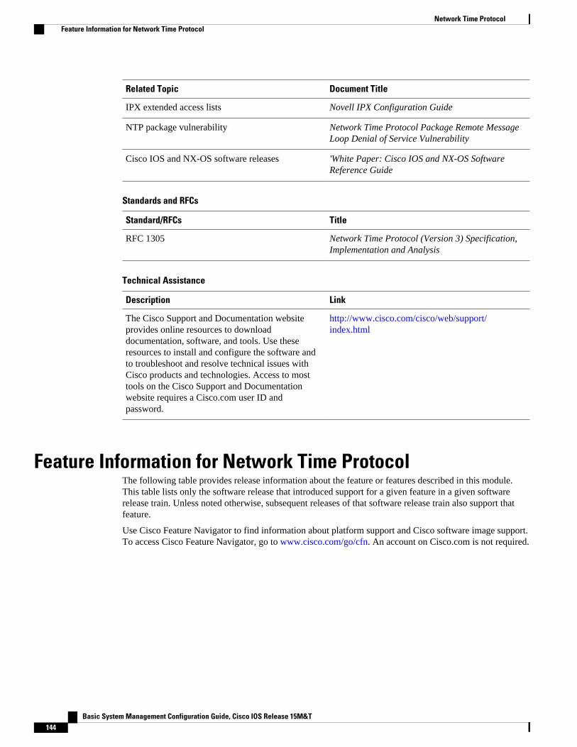
Related Topic Document Title
IPX extended access lists Novell IPX Configuration Guide
NTP package vulnerability Network Time Protocol Package Remote MessageLoop Denial of Service Vulnerability
Cisco IOS and NX-OS software releases 'White Paper: Cisco IOS and NX-OS SoftwareReference Guide
Standards and RFCs
Standard/RFCs Title
RFC 1305 Network Time Protocol (Version 3) Specification,Implementation and Analysis
Technical Assistance
Description Link
The Cisco Support and Documentation websiteprovides online resources to downloaddocumentation, software, and tools. Use theseresources to install and configure the software andto troubleshoot and resolve technical issues withCisco products and technologies. Access to mosttools on the Cisco Support and Documentationwebsite requires a Cisco.com user ID andpassword.
http://www.cisco.com/cisco/web/support/index.html
Feature Information for Network Time ProtocolThe following table provides release information about the feature or features described in this module.This table lists only the software release that introduced support for a given feature in a given softwarerelease train. Unless noted otherwise, subsequent releases of that software release train also support thatfeature.
Use Cisco Feature Navigator to find information about platform support and Cisco software image support.To access Cisco Feature Navigator, go to www.cisco.com/go/cfn. An account on Cisco.com is not required.
Network Time Protocol Feature Information for Network Time Protocol
Basic System Management Configuration Guide, Cisco IOS Release 15M&T144

Table 14 Feature Information for Network Time Protocol
Feature Name Releases Feature Information
Network Time Protocol 11.2(1)
12.2(28)SB
12.2(33)SRA
12.2(33)SXI
12.2(33)SXJ
12.2(50)SY
12.2(58)SE
15.0(1)M
15.1(2)S
15.1(2)SG
NTP is a protocol designed totime-synchronize a network ofmachines. NTP runs on UDP,which in turn runs on IP. NTP isdocumented in RFC 1305.
The following commands wereintroduced or modified: ntpaccess-group, ntp allow modepassive, ntp authenticate, ntpauthentication-key, ntpbroadcast, ntp broadcast client,ntp broadcastdelay, ntp cleardrift, ntp clock-period, ntpdisable, ntp logging, ntp master,ntp max-associations, ntpmulticast, ntp multicast client,ntp server, ntp source, ntptrusted-key and ntp update-calendar.
Cisco and the Cisco logo are trademarks or registered trademarks of Cisco and/or its affiliates in the U.S.and other countries. To view a list of Cisco trademarks, go to this URL: www.cisco.com/go/trademarks.Third-party trademarks mentioned are the property of their respective owners. The use of the word partnerdoes not imply a partnership relationship between Cisco and any other company. (1110R)
Any Internet Protocol (IP) addresses and phone numbers used in this document are not intended to beactual addresses and phone numbers. Any examples, command display output, network topology diagrams,and other figures included in the document are shown for illustrative purposes only. Any use of actual IPaddresses or phone numbers in illustrative content is unintentional and coincidental.
Network Time Protocol
Basic System Management Configuration Guide, Cisco IOS Release 15M&T 145

Example: Configuring Network Time Protocol
Basic System Management Configuration Guide, Cisco IOS Release 15M&T146