
FINAL TECHNICAL REPORT September 1, 2005, through June 30, 2007
Project Title: DEVELOPMENT OF AN INTEGRATED, MULTI-
CONTAMINANT REMOVAL PROCESS FOR SYNGAS CLEANUP ICCI Project Number: 05-1/4.1C-3 Principal Investigator: Howard S. Meyer, Gas Technology Institute Other Investigators: Dr. Diana Matonis, Gas Technology Institute Dr. Scott Lynn, University of California (Consultant) Dr. Albert Tsang, ConocoPhillips (Partner) Project Manager: Dr. Ronald Carty, ICCI
ABSTRACT
The overall objective of this project is to undertake the development of an integrated multi-contaminant removal process in which hydrogen sulfide, carbonyl sulfide, ammonia, chlorides and heavy metals, including mercury, arsenic, selenium and cadmium, present in the coal-derived syngas will be removed in a single process step. To accomplish this, a novel process called UCSRP-HP (University of California Sulfur Recovery Process-High-Pressure) directly converts H2S into elemental sulfur at 285°F to 300°F and at any given sour gas pressure. Other contaminates, such as NH3, HCl and trace heavy metals, are also removed in a separate section of the same reactor column. The process is tightly integrated and is expected to be significantly more economical both in terms of capital and operating costs because it replaces with one single unit the acid-gas removal, Claus and SCOT units used in conventional sulfur management schemes, as well as removing trace contaminants that effect downstream equipment. During this research, data critical to developing and evaluating UCSRP-HP technology for multi-contaminant removal from syngas derived from Illinois #6 coal was obtained. Progress during this period includes the successful completion of a 1,000 hour solvent stability and materials of construction compatibility tests that showed the catalyst was stable, carbon steel is an acceptable material of construction of the reactor/contactor, and that high quality sulfur (up to 99.2% elemental sulfur) was formed. Nine five percent mercury removal, to levels of less than 0.2 ppb, was observed. The bench-scale test unit was fabricated and installed at GTI. It was delayed by third party construction issues under the cofunded DOE and GRI projects and impacted the performance of a number of tasks. Preliminary selenium testing showed that the solubility of H2Se was increased by the presence of an aqueous solution of DEG, ammonia, and chloride over water. Formation of carbonyl sulfide appears to be controllable by the excess of sulfur dioxide. Experimentation has continued to indicate the advantages of the UCSRP-HP for making a significant impact on the purification of coal-derived syngas. Illinois coals will benefit by this low-cost sulfur management option.

EXECUTIVE SUMMARY
Advanced gasification systems are planned to provide synthesis gas feed for advanced, combined cycle power plants; for separation systems for hydrogen production or for separating CO2 for sequestration purposes; or for chemical conversion plants. All of these advanced applications will require that any sulfur-containing species, as well as other contaminants, be reduced to parts-per-million (ppm) or in some cases parts-per-billion (ppb) levels. For acid-gas and trace contaminant removal, technologies that are either currently available or under development include: low-temperature or refrigerated solvent-based scrubbing systems using amines, such as MDEA, or physical solvents, such as Rectisol, Selexol, Sulfinol, low temperature sorbents, such as sulfur-impregnated carbon, or high temperature sorbents (not yet demonstrated at commercial scale). However, these gas-cleaning processes operate at temperatures that are either below or above the temperature of the downstream processing operations (for gas turbine fuel systems and catalytic synthesis processes), which are in the range of 300 to 700°F. These temperature differences lead to lower energy efficiencies: the low-temperature clean-up processes require temperature reductions to below 100°F and then reheating to downstream process requirements; the high-temperature sorbent systems operate at 1000°F, leading to unnecessary gas stream corrosivity. The development of desulfurization systems that can be matched to the elevated temperature and pressure conditions of gasification processes (i.e., temperatures in the range of 300-700 oF and pressures in the range 400-1200 psig) and that can be integrated with the warm-gas cleanup of other contaminants (trace components and heavy metals) is, therefore, of critical importance for early commercialization of advanced gasification technologies being promoted by U.S. DOE in the FutureGen and Clean Coal Power Initiative programs. GTI is developing the UCSRP-HP (University of California Sulfur Recovery Process-High-Pressure) process, an integrated multi-contaminant removal process whereby coal-derived syngas is sent first to an absorbing column where chlorides and ammonia, as well as trace heavy metals (mercury, selenium, arsenic, and cadmium) are removed from the gas stream. The partially cleaned gas then passes to a reactor column at a temperature above the melting point (247°F) and below the polymerization temperature (310°F) of elemental sulfur and a gasification pressure of 400 psig (or any higher pressure). Hydrogen sulfide in the syngas, together with injected sulfur dioxide, dissolves in a solvent that is circulated co-currently or counter-currently in the column. The Claus reaction is carried out in the liquid phase. Sulfur is only sparingly soluble in the solvent and so forms a separate liquid phase. The solvent contains a homogeneous liquid catalyst (less than 1% by weight of the solution). The catalyst is a commonly available and inexpensive material that does not degrade nor dissolve in the sulfur. The water formed in the Claus reaction vaporizes and forms part of the syngas. One-third of the recovered sulfur product is burned with oxygen (if an oxygen-blown gasifier is involved this would be a fraction of the oxygen requirement for the process), and fed to the reactor column. The process is ideal for syngas desulfurization at 285 to 300°F and at any given pressure (higher the better) and offers a tighter integration with the process for removal of trace

contaminants and heavy metals. It is expected to be significantly lower in capital and operating cost compared to conventionally applied amine or physical solvent based acid-gas removal process followed by Claus/SCOT process plus systems to remove other contaminants. The current project is a laboratory program to obtain critical process data for the treatment of syngas derived from Illinois basin coals. The ultimate application of this process will favor high sulfur coals, such as Illinois #6, by reducing the clean up costs and providing an environmentally benign facility to economically utilize these coals. The specific objectives of the project includes (i) design, construction and operation of UCSRP-HP bench-scale unit with up to 20 lb/day sulfur production capacity to gather data for further verification of the process concept, measuring contaminant removal efficiencies, reaction kinetics and optimization of process parameters for designing a pilot-scale demonstration unit for Phase-II study, (ii) investigation of long-term (i.e., 1000 hrs) solvent stability by exposing the solvent to syngas with all the contaminants that may be present in the feed to UCSRP-HP reactor, (iii) investigation of metal corrosion related issues for selecting suitable material of construction for UCSRP-HP reactor, (iv) development of an Aspen-Plus based computer simulation model, and (v) techno-economic evaluation of the process applied to syngas cleanup for a 500 MWe coal-based IGCC power plant. This projected was co-funded by the U.S. DOE through National Energy Technology Laboratory (NETL) under their funding opportunity announcement number DE-PS26-04NT42249. The funding received from ICCI was used to conduct work under each task using test conditions and gas compositions representative of Illinois # 6 coal. Task 1, the design and fabrication of the bench-scale unit, was funded in total through DOE and GRI funds. The work was contracted to NATCO Group, Inc. Kalkaska, MI. The unit is centered on a 4-inch-outer-diameter by 36-inch-high bench-scale co-current, packed bed reactor. The simulated feed gas used in these experiments will contain synthesis gas components including hydrogen sulfide, sulfur dioxide, and nitrogen. The flow rate of simulated feed gas through the packed bed was set to be between 20-100 scfh. The operating condition ranges for the bench-scale packed bed reactor is from ambient temperature to 300°F and pressures from atmospheric to 1000 psig. The unit was delivered to GTI and is being installed in the Gas Processing Laboratory. Due to delays in fabrication and delivery of the bench-scale unit, experimental work was focused on filling the critical data gaps on the laboratory scale. Task 2 included the experimental work of this project. A long-term, 1,000 hour test was performed with a synthetic syngas mixture in a four liter, jacketed, stainless steel pressure vessel at 400 psig and 275°F to study solution stability and materials of construction issues. Mixtures of H2S, syngas, and SO2 flowed through the solvent and out through a scavenging system to assure there was no sulfur releases from our vent streams. The solution was periodically analyzed for the solvent and catalyst concentration to determine stability. Corrosion coupons were exposed in the gas and liquid phases in the vessel and analyzed for metal loss, pitting, and other corrosion issues.

The results from this test showed good stability for the solvent and catalyst. Approximately 2.3% of DEG solvent degraded to tetraglyme. Tetraglyme is a potential substitute for DEG since it is less volatile and has a higher H2S solubility than DEG. However, tetraglyme is more viscous. Therefore conversion of the solvent is not a significant issue. Approximately 25% of catalyst at 0.2% by weight of solution broke down to 3-methylpyridine and 4-formylpyridine. These pyridines are also active catalyst and did not appear to affect reactivity. During the testing, COS was formed. This became an issue that is addressed later. Without any washing or other preparation techniques, the sulfur that was formed during this test was 99.2% pure. The target for commercial purity is greater than 99.5% sulfur. Metal Samples Inc. provided the standard corrosion coupons and independent analysis of these coupons after exposure of 1,000 hour. The coupon results for corrosion showed no pitting or etching. Weight losses for uncoated 1010 carbon steel and stainless steel samples in the chamber were 0.02 and 0.008 g, respectively. The corrosion rates were 0.52 mils/year and 0.23 mils/year over the 1,000 hour period; below 2 mils/year is considered excellent corrosion inhibition. The coupons in the gas and in the liquid phase showed essentially the same weight loss and corrosion rate. These tests verified the use of carbon steel as an acceptable material of construction for the process. GTI’s Vapor-Liquid Equilibrium (VLE) unit was modified to obtain mass transfer and kinetic measurements. This required sampling of not only the gas and liquid phases in the VLE cell, but also of the continuous running phase. In a typical experiment, the reactor is filled with the desired amount of liquid, and the system is allowed to equilibrate to the desired temperature. Next, the gas flow to the cell is set to the desired rate or pressure, and passed directly to the cell. The GC is able to measure the reactor inlet concentration. The stirrer is switched to the desired rate, and the flow is led through the reactor until the achievement of a pseudo steady state, as indicated by a constant concentration reading from the GC or pressure reading, marking the end of the experiment. Trace contaminant removal testing was conducted under a number of different conditions. Mercury and selenium removal testing were carried out at atmospheric pressure in quartz reactors. Elemental mercury was introduced into the system through a permeation tube and analyzed by an Ohio Lumex instrument. Selenium was introduced as H2Se in nitrogen through a cylinder mixture along with cylinder supplies of anhydrous ammonia and anhydrous hydrogen chloride. Samples were sent to GTI’s Analytical Department for analysis. Carbonyl sulfide formation was studied at pressures up to 500 psia. Gas chromatographs were used to measure input and outlet sulfur compounds. The mercury concentration in the vapor phase was brought down from 44,300 ng/m3 to 1,900 ng/m3, achieving 95.7% mercury removal. This concentration is equivalent of 0.2 ppb by weight in the product stream. This is well within the DOE target of less than 5 ppb in the outlet gas. Selenium removal is based on the solubility of H2Se into DEG. Preliminary testing showed that its solubility is affected by the presence of ammonium chloride. The solubility increased at least three fold by the presence on the ammonium

chloride at 275°F. Further testing is required to determine the operating conditions to achieve the 0.2 ppm concentration target in the product gas. Carbonyl sulfide adds to the sulfur targets for the product gas. COS is formed in the gasifier, but may be shifted to H2S if a sour water gas shift catalyst is used prior to the UCSRP-HP process. Potential chemical formation pathways were identified and studied. Preliminary results have shown that an excess of SO2 will mitigate any COS from forming and will promote the COS reaction to form H2S. To support the Task 3, computer simulation, VLE equipment was used to determine the Henry’s Law constant for H2S and SO2 in DGM. This is needed to determine the solubility of these compounds within the Aspen Plus simulation model. The results showed that calculated Murphree tray efficiencies are in good agreement with experimental data and therefore validating our model for calculating reasonable high pressure and temperature tray efficiencies. Aspen Plus models have been completed for H2S and SO2 absorption in DGM, the sulfur furnace, and the absorption of ammonia, chloride, and H2Se in DEG. The techno-economic analysis of Task 4 requires additional effort to complete. ConocoPhillips provided a gas composition that constitutes the feed to the UCSRP-HP. This was based on their EGAS gasification process treating Illinois #6 in an IGCC application. They assumed that their process would not have to remove or recycle chlorides or ammonia, since they will be removed in the UCSRP-HP. This simplified their flow sheet. Qualitatively, the UCSRP-HP continues to offers great potential as an integrated sulfur and trace component removal technology to significantly lower the cost of electricity or chemicals from coal-derived gasification processes. The UCSRP-HP process continues to be a viable technology that can significantly simplify the clean-up of coal-derived syngas. The current program has shown that the solvent and catalyst will remain active and stable under operating conditions and that lower cost carbon steel can be used as the material of construction within the process equipment. The project has shown mercury levels can be reduced to 0.2 ppbw levels through a precipitation mechanism that is the same as expected for arsenic and cadmium. Testing has indicated that removal of selenium, through solubility of H2Se, should be achievable. Sulfur purity of 99.2% was achieved. Reaction pathway testing indicates that COS formation and capture can be controlled in the system. While the techno-economic evaluation of the process was not yet completed, Aspen Plus is a viable simulation program for preparing the required material and energy balances. Further laboratory development of the UCSRP-HP is recommended. That program should complete the work initiated here on heavy metal, ammonia, and halogen removal, COS control, and regeneration of the DEG solvent system used to remove these components. These results should be incorporated into the computer simulation model and the economic evaluation completed for an IGCC and a hydrogen production plant using Illinois #6 as the feed material. This work would be coordinated with the continuation of the DOE program.

1
OBJECTIVES
The overall objective of this project is the development of an integrated multi-contaminant removal process in which H2S, NH3, HCl and heavy metals including Hg, As, Se and Cd present in the coal-derived syngas will be removed to specified levels in a single process step. To accomplish this, we used the high pressure University of California Sulfur Recovery Process (here after referred to as UCSRP-HP) that directly converts H2S into elemental sulfur at 285°F to 300°F and at any given sour gas pressure. Other contaminates such as NH3, HCl and other trace contaminants are also removed in separate sections of the same reactor column. The specific objectives of the project include (i) design, construction and operation of UCSRP-HP bench-scale unit with up to 20 lb/day sulfur production capacity to gather data for further verification of the process concept, measuring contaminant removal efficiencies, reaction kinetics and optimization of process parameters for designing a pilot-scale demonstration unit for Phase-II study, (ii) investigation of long-term (i.e., 1000 hrs) solvent stability by exposing the solvent to syngas with all the contaminants that may be present in the feed to UCSRP reactor, (iii) investigation of metal corrosion related issues for selecting suitable material of construction for UCSRP reactor, (iv) development of an Aspen-Plus based computer simulation model, and (v) techno-economic evaluation of the process applied to syngas cleanup for a 500 MWe coal-based IGCC power plant. This projected was co-funded by the U.S. DOE through National Energy Technology Laboratory (NETL) under their funding opportunity announcement number DE-PS26-04NT42249. The funding received from ICCI was used to conduct work under each task using test conditions and gas compositions representative of Illinois # 6 coal.
INTRODUCTION AND BACKGROUND
This work relates to the ICCI’s program goal 4.1C - development of novel methods for syngas cleanup which must be an alternative or an improvement of current methods of amine scrubbing. The number of coal gasification facilities in design is growing every year. Advanced gasification systems are planned to provide synthesis gas feed for advanced, combined cycle power plants; for separation systems for hydrogen production or for separating CO2 for sequestration purposes; or for chemical conversion plants. All of these advanced applications will require that any sulfur-containing species, as well as other contaminants, be reduced to parts-per-million (ppm) or in some cases parts-per-billion (ppb) levels. For acid-gas removal, technologies that are either currently available or under development include: low-temperature or refrigerated solvent-based scrubbing systems using amines, such as MDEA, or physical solvents, such as Rectisol, Selexol, Sulfinol, or high temperature sorbents (not yet demonstrated at commercial scale). However, these gas-cleaning processes operate at temperatures that are either below or above the temperature of the downstream processing operations (for gas turbine fuel systems and catalytic synthesis processes), which are in the range of 300 to 700°F. These temperature

2
differences lead to lower energy efficiencies: the low-temperature clean-up processes require temperature reductions to below 100°F and then reheating to downstream process requirements; the high-temperature sorbent systems operate at 1000°F, leading to unnecessary gas stream corrosivity. In advanced gasification applications where a low-temperature absorption process, such as Rectisol or Selexol, is employed to scrub the gas and remove the sulfur compounds, the sulfur-containing species such as H2S and COS are recovered as an acid gas, which then requires a sulfur-recovery process. The modified Claus process coupled with a tail gas treatment (TGT) process such as SCOT are typically used to recover elemental sulfur and produce a dischargeable plant tail gas. The development of desulfurization systems that can be matched to the elevated temperature and pressure conditions of gasification processes (i.e., temperatures in the range of 300-700 oF and pressures in the range 400-1200 psig) and that can be integrated with the warm-gas cleanup of other contaminants (trace components and heavy metals) is, therefore, of critical importance for early commercialization of advanced gasification technologies being promoted by U.S. DOE in the FutureGen and Clean Coal Power Initiative programs. Research at the University of California, Berkeley (UCB), coupled with experimental work at Gas Technology Institute (GTI), is leading to the development of an integrated multi-contaminant removal process whereby syngas is sent to a reactor column at a temperature above the melting point (247 oF) and below the polymerization temperature (310 oF) of elemental sulfur and a gasification pressure of 400 psig or higher. H2S in the syngas, together with injected SO2, dissolves in a solvent that is circulated in the column. The Claus reaction is carried out in the liquid phase. Sulfur is only sparingly soluble in the solvent and therefore forms a separate liquid phase. The solvent contains 3-Pyridinemethanol, a homogeneous liquid catalyst at less than 1% by weight of the solution. This catalyst is a commonly available and inexpensive material that does not degrade nor dissolve in the sulfur. The water formed in the Claus reaction vaporizes and forms part of the syngas. One-third of the sulfur product is burned with oxygen (if an oxygen-blown gasifier is involved this would be a fraction of the oxygen requirement for the process), and fed to the reactor column. Means are also provided to remove COS, HCl, NH3, and trace heavy metals. The treated gas leaving the reactor column will meet the strict specifications set for H2S and the other contaminants for turbines, fuel cells, and catalytic processes. The process is ideal for syngas desulfurization at 285 to 300 oF and at any given pressure (the higher the better) and offers a tighter integration with the process for removal of trace contaminants and heavy metals. It is expected to be significantly lower in capital and operating cost compared to conventionally applied amine or physical solvent based acid-gas removal process followed by Claus/SCOT process. Testing done at GTI has shown negligible chemical consumption (including catalyst), unlike typical chemicals costs of $300 - $1000 per ton sulfur removed found in competing processes. There is much less need for stainless steels in the process, and no apparent cut-off point in terms

3
of sulfur handling at which Claus/SCOT becomes more economical. This process differs from liquid redox processes in important ways. There is no need for filtering a solid sulfur paste with attendant handling problems and loss of solvent. The sulfur quality can be as good as Claus sulfur due to the low solubility of the solvent in the liquid sulfur, and to the large density difference and ease of liquid/liquid separation in the process. The process can operate at significantly higher temperatures than the liquid redox or CrystaSulf processes, which is of value in IGCC applications. No foaming of the solution occurs since the solvent is non-aqueous and has no surfactant properties. No sticky or solid sulfur is present anywhere in the system so the problems of liquid redox plugging and pump wear would not be present. The UCSRP-HP process, in addition, employs the reaction between H2S and SO2 to sweeten a gas at high pressure in a reactor column under the following conditions: • the organic liquid solvent contains a homogeneous catalyst that promotes the
liquid-phase reaction 2 H2S + SO2 ⇒ 3 S + 2 H2O
• the temperature in the reactor column is above the melting point of sulfur, and • the SO2 is fed in stoichiometric excess to the H2S. Although there is no minimum (or maximum) pressure at which the process can operate, the flow of solvent is reduced and reaction rates are increased at higher pressures. This permits the use of smaller equipment and lowers operating costs; hence the process will be most attractive for the treatment of H2S-containing gases at high pressure. Treatment of Synthesis Gas from Coal Gasification When coal is gasified, the syngas produced may contain not only H2S, but also NH3 and HCl and heavy metals, such as As, Cd, Hg and Se. Before the syngas is used as fuel for a gas turbine or further processing to methane, liquid hydrocarbons or hydrogen, all of the above should be reduced to very low values. A process flow diagram demonstrating one application of UCSRP to this problem is shown in Figure 1. a) Reactor: The countercurrent reactor column is divided into two sections: the scrub section and the reactor section. The sour gas feed enters scrub section, 2A, where it is contacted with a stream of diethylene glycol (DEG) or other glycol ether. At the pressure, temperature and water content of the syngas, the DEG will have a steady-state water content of about 10 to 20 wt%. It will also have substantially smaller, but significant, steady-state contents of NH3 and H2S. As a result, the HCl content of the feed gas will be absorbed very effectively to form highly soluble NH4Cl. A small but significant concentration of NH4HS will also be present in the liquid phase, and the heavy metals As, Cd and Hg will be absorbed to form their respective, very insoluble sulfides. Selenium will be present in the syngas as H2Se and will be absorbed to form highly soluble (NH4)2Se under these conditions. At the bottom of the scrub section the DEG stream is withdrawn and circulated by pump back to the top. A small slipstream of the DEG stream may be withdrawn, perhaps intermittently, for filtration and other treatment
4
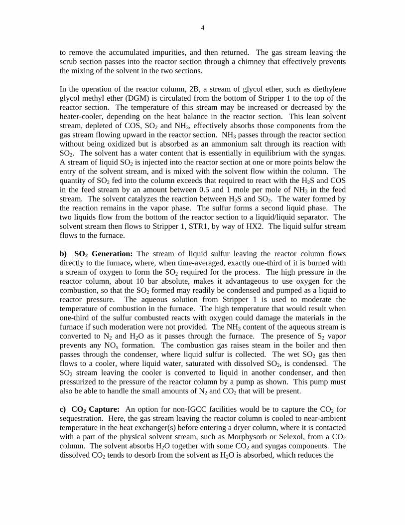
to remove the accumulated impurities, and then returned. The gas stream leaving the scrub section passes into the reactor section through a chimney that effectively prevents the mixing of the solvent in the two sections. In the operation of the reactor column, 2B, a stream of glycol ether, such as diethylene glycol methyl ether (DGM) is circulated from the bottom of Stripper 1 to the top of the reactor section. The temperature of this stream may be increased or decreased by the heater-cooler, depending on the heat balance in the reactor section. This lean solvent stream, depleted of COS, SO2 and NH3, effectively absorbs those components from the gas stream flowing upward in the reactor section. NH3 passes through the reactor section without being oxidized but is absorbed as an ammonium salt through its reaction with SO2. The solvent has a water content that is essentially in equilibrium with the syngas. A stream of liquid SO2 is injected into the reactor section at one or more points below the entry of the solvent stream, and is mixed with the solvent flow within the column. The quantity of SO2 fed into the column exceeds that required to react with the H2S and COS in the feed stream by an amount between 0.5 and 1 mole per mole of NH3 in the feed stream. The solvent catalyzes the reaction between H2S and SO2. The water formed by the reaction remains in the vapor phase. The sulfur forms a second liquid phase. The two liquids flow from the bottom of the reactor section to a liquid/liquid separator. The solvent stream then flows to Stripper 1, STR1, by way of HX2. The liquid sulfur stream flows to the furnace. b) SO2 Generation: The stream of liquid sulfur leaving the reactor column flows directly to the furnace, where, when time-averaged, exactly one-third of it is burned with a stream of oxygen to form the SO2 required for the process. The high pressure in the reactor column, about 10 bar absolute, makes it advantageous to use oxygen for the combustion, so that the SO2 formed may readily be condensed and pumped as a liquid to reactor pressure. The aqueous solution from Stripper 1 is used to moderate the temperature of combustion in the furnace. The high temperature that would result when one-third of the sulfur combusted reacts with oxygen could damage the materials in the furnace if such moderation were not provided. The NH3 content of the aqueous stream is converted to N2 and H2O as it passes through the furnace. The presence of S2 vapor prevents any NOx formation. The combustion gas raises steam in the boiler and then passes through the condenser, where liquid sulfur is collected. The wet SO2 gas then flows to a cooler, where liquid water, saturated with dissolved SO2, is condensed. The SO2 stream leaving the cooler is converted to liquid in another condenser, and then pressurized to the pressure of the reactor column by a pump as shown. This pump must also be able to handle the small amounts of N2 and CO2 that will be present. c) CO2 Capture: An option for non-IGCC facilities would be to capture the CO2 for sequestration. Here, the gas stream leaving the reactor column is cooled to near-ambient temperature in the heat exchanger(s) before entering a dryer column, where it is contacted with a part of the physical solvent stream, such as Morphysorb or Selexol, from a CO2 column. The solvent absorbs H2O together with some CO2 and syngas components. The dissolved CO2 tends to desorb from the solvent as H2O is absorbed, which reduces the

5
DGM-L
FEED
BFW
STEAM
WATER
DGM-R
LIQ-S1
OXYGEN
NH4HSO3
LIQ-S2
GAS-SO2
SO2-GAS
SO2-LIQ
DEG
GAS-OUT
HT-COOL
HX1-H
BOILER
STR-1
LL-SEP
FURNACE CNDNSR-1
HX2
CNDNSR-3
PUMP-5
PUMP-4
PUMP-1
PUMP-3
CNDNSR-2
HX1-C
High-PressureSour Gas
Sulfur Product
Sweet Wet Gas
Application of UCSRP to Removal ofMetals + NH3 + HCl + H2S + COS
from High-Pressure Syngas(gasified coal)S. Lynn 9/2/04
UCSRP-HP4
2B
To DEG Clean-up
From DEGClean-up
2A
ReactorColumn
Figure 1 UCSRP-HP Block Diagram

6
temperature rise that might otherwise occur. The reboiler at the bottom of column heats the solvent sufficiently to strip out a large fraction of the CO2, and syngas dissolved in it while retaining substantially all of the H2O. The solvent stream then flows to the H2O stripper. The gas stream leaving the dryer column flows to the CO2 column and is contacted with freshly stripped, cooled solvent. A major fraction of the CO2 in the natural gas stream is absorbed. The reboiler at the bottom of the CO2 column heats the rich solvent sufficiently to strip out a large fraction of the syngas while retaining substantially all of the CO2. The reboiler serves also to cool the stream leaving the solvent strippers. The product gas leaving the CO2 column will have a CO2 content of 1 vol % or less and will be dried to a dew point of 0oC or to meet process specifications. The CO2-rich solvent then flows to the CO2 stripper, which operates near ambient pressure and removes most of the CO2 from the solvent. The solvent contains about 1 wt% water, so that most of the stripping vapor in the reboiler of the CO2 stripper is H2O and the temperature is low enough to prevent thermal degradation of the solvent. No water is removed from the system in the CO2 stripper; the water vapor condensed at the top is returned as a reflux that prevents loss of solvent vapor. The captured CO2 can then be compressed for transfer to a sequestration facility. d) Syngas Temperature Recovery: To maximize thermal efficiency, it is preferable to minimize the temperature drop during sulfur removal. This process is preferably operated above the melting point (247 °F) and below the polymerization temperature (310
°F) of elemental sulfur. Therefore, if the temperature of the sour syngas feed to the reactor is above this range, stream 1 will be passed through a gas-gas heat exchanger, HX1. The feed gas temperature will be reduced to about 280 to 300°F by exchange with the treated syngas stream 5. This way we expect that almost all heat will be recovered and the maximum temperature differential between sour feed gas and treated sweet gas will be around 30 to 40°F. This technology offers great advantages for Illinois basin coals. The ability to reduce the cost for sulfur and other coal impurities will lead to a greater usage of the high sulfur Illinois coals that are not currently competitive for power generation.
EXPERIMENTAL PROCEDURES
The overall approach for this project is the use of simulated coal-derived syngas for laboratory testing of the UCSRP-HP process, augmented by computer simulations. These gas mixtures were fairly complex, consisting of a number of components down to the parts per million (ppm) level. This was deemed to be a reasonable compromise between simple gas mixtures without the major syngas components, such as H2S and SO2 in N2, and a gas from an operating gasifier for the scale of development. Solvent Degradation and Materials of Construction Experiment – A 1,000 hour test was conducted to study solvent stability and the corrosivity of the system on potential reactor materials of construction. As noted previously, the reactor section of the process

7
will have SO2 and H2S being converted to molten, elemental sulfur in a DGM solvent contains a homogeneous liquid catalyst. It is important to verify that the catalyst and solvent remain stable and active, as well as verifying that carbon steel vessels will be acceptable to prevent the expense of requiring stainless steels. Figure 2 shows the schematic diagram of the apparatus that was used. It was run at 400 psi and 275oF with an average outlet flow rate of 0.2 L/min. It mainly consists of a 4L jacketed, cylindrical, stainless steel vessel with a stainless steel top and bottom plate equipped with a variable speed stirrer, and bottom drain valves to periodically remove sulfur produced and the sample during the reaction. All the surfaces exposed to the chemicals are stainless steel or Teflon to withstand temperature and the corrosive conditions within the reaction vessel. The inlet gases are heated using heating tape and the wall is electrically heated. Temperature of the reaction medium is measured with a K-type thermocouple and controlled using PID type temperature controller. H2S/syngas and SO2 inlet pipes and exit gas pipe from the reactor were heated to avoid the plugging of flow lines. Flow rates of the feed gas were controlled manually by means of precession needle valves and monitored by separate mass flow meters. The exit gas stream passed through the gas-washing bottle to condense water produced in the reaction, which was then sent to a second gas-washing bottle filled with 50% sodium hydroxide (NaOH) solution to consume all the unreacted H2S before it was vented. H2S and SO2 leak detectors were placed near the setup to detect any leaks. 2200 ml of 94.5% diethylene glycol methyl ether (DGM), 5% water (H2O) and 0.5% 3-pyridyl carbinol (3-HP) was taken into the reaction vessel. The solution was stirred well and heated to 135°C. After the desired temperature was achieved, SO2 and H2S/sygas were introduced into the reactor. The flow rates of H2S and SO2 were controlled manually by means of precession needle valves (outlets) and by separate mass flow meters (inlets) to maintain a constant reactor pressure of 400 psia. The outlet flow was measured with a bubble flow meter and the total outlet flow was 0.2 slpm. The ratio of inlet flows was kept at 1.8% SO2 to 0.9% H2S during the experiment. The experiment was conducted at 400 psia and 275°F for 1,000 hours. Small liquid samples (5-10 mL) were withdrawn from the reactor at regular intervals and analyzed by GC/MS. An initial analysis of the solvent was performed to be able to identify any degradation products during the experiment. To study the corrosive nature of the reaction mixture, four, pre-weighed, photographed, 1” × 1” × 1/16” metal coupons (2 uncoated carbon steel Grade 1010 and 2 stainless steel Grade 304) were mounted on two diffuser shafts at two different location such that one was half way submerged and the other was always fully submerged in the solution for each metal. Grade 304 was chosen because it is the “standard 18/8 stainless”; it is the most versatile and most widely used stainless steel. At the end of the 1,000 hour experiment, these coupons were carefully dismounted, and sent for analysis to determine the type and rate of corrosion in the units of mills per year (mpy). Metal Samples Inc. provided the standard corrosion coupons and independent analysis of these coupons after

8
exposure of 1,000 hour.
Figure 2 UCSRP-HP Solvent Degradation and Corrosion Experimental Layout
Trace Contaminant Removal – Laboratory units for testing the absorption and conversion of trace contaminants in coal-derived syngas were prepared. Separate tests with mercury as elemental mercury, selenium as H2Se, chloride as HCl, and ammonia as NH3 were initiated with diethlyene glycol (DEG) as the solvent. A permeability tube was used to introduce the mercury into the gas stream. H2Se, HCl, and NH3 were added as separate gases from prepared cylinders. Figure 3 illustrates the schematic diagram and Figure 5 is a photograph of the mercury vapor adsorption apparatus. The Hg source was a mercury permeation tube (VICI Metronics. Inc., CA) as seen in Figure 4. A bath maintained the required stable temperature. The carrier gas was high purity grade nitrogen gas. The reactor temperature was regulated by an electrical jacket fitted around it. Teflon and stainless tubing was selected as connecting materials. A bubble flow meter measured the inlet, intermediate and outlet flows from the reactor. The tubing and valving were such that the selection of which flow rate to be measured could be made during the experiment with the same bubble flow meter. An Ohio Lumex analytical instrument was employed for measuring the mercury concentrations. Initially, straight through “blank” experiments were performed to measure the Hg0 concentration in the inlet gas to the reactor. The main limitation of inlet

9
Hg0 concentration is the measurement maximum of the Ohio Lumex Instrument, which can measure Hg0 concentration up to 200µg/m3 (STP). Thus, if the concentrated mercury vapor needed to be diluted for measurement purposes, a bypass line was installed with nitrogen gas before being introduced into the reactor. This was not necessary for these runs because the average inlet mercury concentration tested was 44.3±0.4 µg/m3. We also observed that the concentration of mercury decreased as the nitrogen flow rate over the permeation tube increased, as expected.
Figure 3 Trace Contaminant Testing Apparatus
Figure 4 Mercury Permeation Tube
Figure 5 Mercury Vapor Sorption
Apparatus
A new test system was installed and initial runs made to study the conversion and separation of ammonia, chlorides, and selenium from a simulated syngas. Figure 6 is a

10
photograph of the test apparatus. The selenium, ammonia, and chloride sources are high pressure cylinders containing 15% H2Se in nitrogen, 99+% anhydrous ammonia, 99+% HCl, respectively. The carrier gas was high purity grade nitrogen gas. All gases were introduced into the reactor simultaneously via the different inlets, pressure regulators and rotameters. The reactor temperature was regulated by an electrical jacket fitted around it. Teflon and stainless tubing was selected as connecting materials. A bubble flow meter measured the inlet, intermediate and outlet flows from the reactor. The tubing and valving were such that the selection of which flow rate to be measured could be made during the experiment with the same bubble flow meter.
Figure 6 Trace Component Removal with Ammonia, Chloride, and Selenium
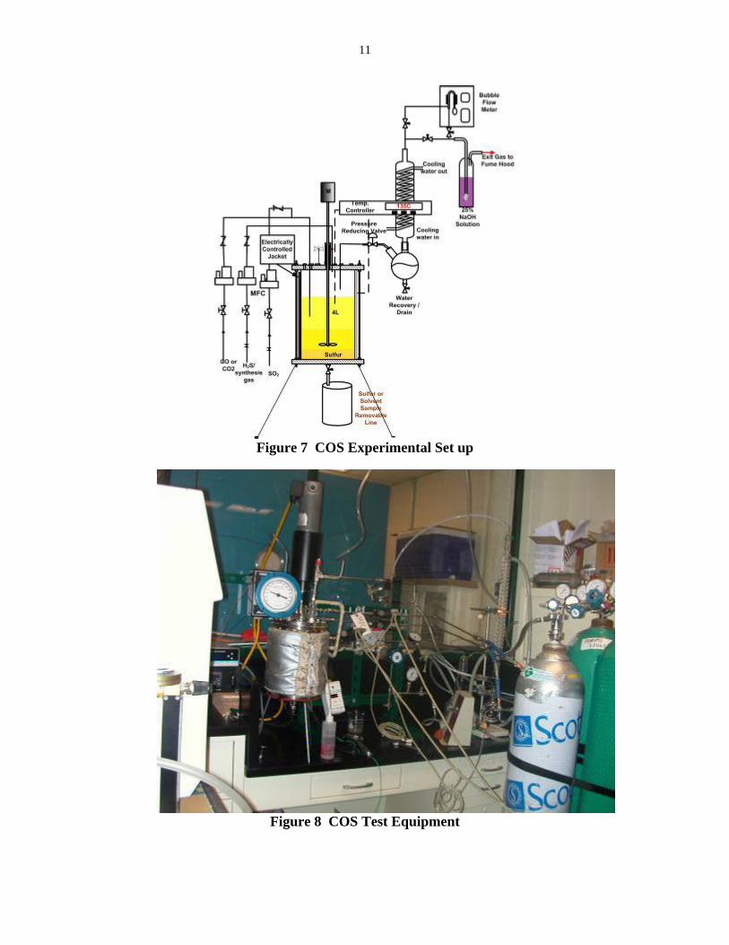
The fate of COS in the process is a critical issue for the success of the process. The mechanism for COS either forming or being consumed under our operating conditions is being studied. The test system is shown schematically in Figure 7 and as a photograph in Figure 8. The apparatus consisted of a 4 L steel reaction vessel equipped with a variable speed stirrer. The vessel was also equipped with a bottom drain valve that was used to periodically remove sulfur produced during a side reaction. The reaction vessel was designed to be operated from 120-160°C at pressures up to 500 psia. The exit gas stream passed through the gas-washing bottle to condense water produced in the reaction and then to a second gas-washing bottle filled with 50% sodium hydroxide (NaOH) solution to consume all the untreated H2S before it is sent to vent. H2S and SO2 leak detectors were placed near the setup to detect any leaks. The flow rates of H2S and SO2 were controlled by using two Brooks Mass Flow Controllers (MFC) and a back pressure regulator was used to maintain a constant reactor pressure of 400 psia. The outlet flow was measured with a bubble flow meter.
11
Figure 7 COS Experimental Set up
Figure 8 COS Test Equipment

12
Vapor-Liquid Equilibrium Experimentation –The experimental set-up for mass transfer and kinetic measurements was build around a stirred cell reactor, see Figure 9 and Figure 10. The equilibrium cell is made of nonmagnetic stainless steel 9 1/8” in length and 3” inside diameter. The feed system allows up to three gas sources/cylinders to be used at a time; pre-blended gas mixtures are employed to increase the number of components tested. The gases are blended by means of partial pressure, utilizing a high-precision pressure gauge and then added to the test cell by means of system pressure. Liquid is drawn into the test cell by vacuum. The equilibrium vessel has a nominal volume of one liter and is rated for operation up to 5,000 psig. This vessel is contained in an environmental chamber, so that temperatures can be controlled between -85°F to 350°F. The vapor-liquid system is mixed thoroughly by a magnetically-driven agitator that is supplied with a hollow shaft for gas circulation and is extended so that the agitator drive can be located outside the environmental chamber. A PLC-based control system is provided to assure reliable and repeatable operation. Data are logged regularly from the control system into a dedicated computer for permanent storage and with flexible capabilities for displaying parameter trends during and after the experiments. Because of the presence of potentially harmful gases, the unit is provided with an ambient gas monitor for H2S, CO, and combustible gas. All process and relief vents are collected into a single stream and scrubbed in a caustic solution prior to entering the building vent system. This arrangement allowed the Vapor-Liquid Equilibrium Unit to be run in the batch phase for both the liquid and gas phase only with no sampling. This is adequate for furnishing vapor-liquid equilibrium information from P-V-T measurements, with no need for sampling or analysis of either phase when the assumption that the vapor contains essentially none of the nonvolatile components is valid or the vapor consist of a pure gas. However, when dealing with a more volatile liquid phase or when more complex static equilibrium studies are necessary, such as reaction kinetics, not only must gas and liquid sampling be performed, but the consideration of a continuous running phase must be included. Two gas chromatographs, with a range of detector options, analyze the vapor and liquid samples in these cases. In a typical experiment, the reactor is filled from vacuum with the desired amount of liquid, and the system, is allowed to equilibrate to the desired temperature. Next, the gas flow to the cell is set to the desired rate or pressure, and passed directly to the cell. The GC measures the reactor inlet concentration. The stirrer is switched to the desired rate, and the flow is led through the reactor until the achievement of a pseudo steady state, as indicated by a constant concentration reading from the GC reading or pressure reading, marking the end of the experiment. The liquid phase mass transfer coefficients was determined by monitoring the pressure drop during the absorption of CO2 in water, while operating both gas and liquid phases in batch mode. The variation of the CO2 partial pressure with time, obtained from molar balances for CO2 over both phases is given by

13
)(
)()
)
bulkbulk
lx
bulkbulk
gy
xH
yKN
HxyKN
−=
−=
for a dynamic solution of the liquid mass transfer coefficient directly from the initial and time dependent concentration readings. Pressure readings at the initial and equilibrium points can then directly be used to obtain Henry’s coefficient as follows which is the solubility mulitplied by RT.
Figure 9 High Pressure Vapor Equilibrium Cell Techno-Economic Analysis – ConocoPhillips will be performing a techno-economic evaluation of the UCSRP-HP incorporated into their E-GAS entrained gasifier system using Illinois #6 coal for power generation in an IGCC mode. GTI will utilize the data obtained in the project to establish an Aspen Plus simulation model of the UCSRP-HP process based on inlet conditions from ConocoPhillips and deliver a material and energy balance as well as capital and operating costs. GTI will provide ConocoPhillips with the design for the UCSRP-HP with the contaminant removal of H2S down to 50 ppb, NH3 down to 0.1%, and HCl down to 1 ppm as per DOE’s objective to develop a cleanup process that will result in a syngas suitable for fuel cell applications.
( ) RTVV
PPP
Hg
l
fi
f
−=

14
Figure 10 Schematic of GTI Vapor-Liquid Equilibrium Cell
RESULTS AND DISCUSSION
Task 1 – Bench-Scale UCSRP-HP Reactor Setup Design, Construction and Commissioning – The design of the bench-scale unit was completed and NATCO completed fabrication of the pressure vessels and procurement of other equipment according to the process and instrumentation diagram presented in Figure 11. The installed equipment in GTI’s gas processing laboratory can be seen in Figure 12. As can be seen from in the figure, the main unit where absorption and reaction will take place is in the absorber. It is a 4-inch-outer-diameter by 36-inch-high bench-scale packed bed reactor. The simulated feed gas used in these experiments will contain synthesis gas components including hydrogen sulfide, sulfur dioxide, and nitrogen. The flow rate of simulated feed gas through the packed bed was set to be between 20-100 scfh. The operating condition ranges for the bench-scale packed bed reactor is from ambient temperature to 300°F and pressures from atmospheric to 1000 psig. Heat is generated as a result of the exothermal chemical reaction between hydrogen sulfide and sulfur dioxide. Heat may also be generated when large amounts of solute are absorbed into the liquid phase, due to the heat of solution. The resulting change in temperature along the height of the absorber column may damage equipment and reduce absorption efficiency. This problem can be avoided by adding cooling coils to the

15
Figure 11 Bench-Scale Unit P&ID
Figure 12 Bench-Scale Unit at GTI
column or by adding quench water as shown for this small vessel. The evaporation of water will cause a substantial cooling within the absorber to offset the heat generated if it
Knockout Scrubber – V104/105
Absorber Column – V100
HP Flash – V101
Separator –
Water Saturator – V300
Methane Saturator – V103
Quench Water Vessel – V200

16
deemed necessary for temperature control. Heat losses in the small column may be sufficient to control temperature. A thermocouple, as shown in the diagram, will regulate the addition of water to the system as necessary. A once-through caustic scrubber was chosen as a simple and effective system to remove any H2S and SO2 remaining at the end of the process before venting to our internal compressor system. Other scrubber systems including lime/limestone systems were looked at, but many have other prohibitive restrictions, e.g. limestone systems are typically limited to fairly weak gases of SO2 and can be adversely affected by rapid changes in concentration. This is true because the pH decreases as the SO2 concentration increases via SO3
-2 and HSO3-1 concentrations. Thus, for a laboratory-scale system, the
caustic scrubber is both economical and efficient, which are not as sensitive to these fluctuations because the following SO2 absorption chemistry that holds in a caustic scrubber:
SO2 (g) + 2NaOH = Na2SO3 + H2O
SO2 (g) + NaOH = NaHSO3
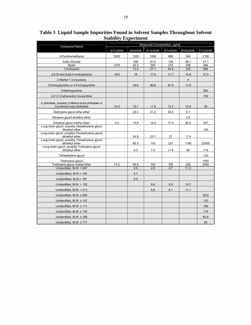
The unit is enclosed in a walk-in Plexiglas enclosure operated at a negative pressure with respect to the rest of the laboratory to ensure containment of any toxic or combustible gas releases. Commissioning of the unit is awaiting delivery of a chiller, the control system, and minor tubing connections. Task 2 – Laboratory Experiments – None of the planned testing in the bench-scale unit was performed due to the late arrival of the unit. The subtasks affected are indicated below. Task 2.1 – Solvent Degradation and Corrosion – The fresh solvent was analyzed by the GTI Analytical Laboratory in order to identify any degradation of the solvent during the test. The mass spectrometer was set up to 'bypass' the diethylene glycol methyl ether peak as it is the major component in the sample, essentially serving as a solvent for the sample. The results of the GC/MS of the fresh solvent are presented in Table 3. Diethylene glycol methyl ether (DGM) is not listed as a component because the system is set up to bypass DGM as it is a major component in such high concentration that it will cause the GC/MS to shut down as a safety measure, or if the safety does not activate in time, it would blow out a filament. The catalyst, 3-pyridinemethanol, appears to diminish in concentration during the experiment, but comes back when the gases and reaction are stopped as indicated in the 7/12 measurement. This would be expected as the catalyst partakes in the reaction, but is not itself consumed. The results from this test showed good stability for the solvent and catalyst. Approximately 2.3% of DEG solvent degraded to tetraglyme. Tetraglyme is a potential substitute for DEG since it is less volatile and has a higher H2S solubility that DEG. However, tetraglyme is more viscous. Therefore conversion of the solvent is not a significant issue. Approximately 25% of catalyst at 0.2% by weight of solution broke down to 3-methylpyridine and 4-formylpyridine. These pyridines are also active catalyst and did not appear to affect

17
reactivity. The gas analysis indicates that the COS is created by reaction of carbon dioxide with the sulfur that is formed. Table 2 shows that possibly up to 30 ppmv may have formed via this reaction pathway. At these levels, we are at the limit of the gas chromatograph accuracy and may not actually be forming any carbonyl sulfide. COS is in the Wabash River gasifier syngas at about 700 ppm. However if carbonyl sulfide has formed, it is in equilibrium with the reverse reaction of carbonyl sulfide combining with sulfur dioxide to reform carbon dioxide and sulfur. Therefore, withdrawal of sulfur from the reactor should further minimize carbonyl sulfide formation. Further testing of COS was initiated as explained later in this paper. The sulfur that was formed during this test was also analyzed for sulfur purity. Without any washing or other preparation techniques, the sulfur was 99.2% pure. The commercial target for sulfur purity is greater than 99.5%.
Table 1 GC/MS Analysis of DGM Solvent Mixture Prior to Experiment Start
Metal Samples Inc. provided the four standard uncoated carbon steel Grade 1010 and stainless steel Grade 304 corrosion coupons and an independent analysis of these coupons after exposure of 1,000 hour. The coupon results for corrosion showed no pitting or etching as shown on Figure 13. Weight losses for uncoated 1010 carbon steel and stainless steel samples in the chamber were 0.02 and 0.008 g, respectively. The corrosion rates were 0.52 mils/year and 0.23 mils/year over the 1,000 hour period; below 2 mils/year is considered excellent corrosion inhibition. The coupons in the gas and in the liquid phase showed essentially the same weight loss and corrosion rate.

18
Table 2 Gas Chromatograph of the Vapor Stream in the 1,000 hour Degradation
Experiment
These tests verified the use of carbon steel as an acceptable material of construction for the process.
Task 2.2 – Reaction Kinetics – No significant activity due to the unavailability of the bench-scale unit. Task 2.3 – Hydrodynamics of the Gas-Liquid-Liquid Flow – No significant activity due to the unavailability of the bench-scale unit. Task 2.4 – Trace Contaminants Removal – Mercury vapor phase concentration curves in the presence of DEG are presented in Figure 14. The spike at about 4400 seconds resulted from bypassing the reaction vessel to ensure that mercury was still flowing. DEG improved the extent of the reaction of Hg with hydrogen sulfide over that observed in a vapor phase reaction; i.e., 95% of the mercury reacted with the hydrogen sulfide in the presence of DEG, while only 58% reacted in the vapor phase, as can be seen Figure 15. This is important because it is desired to bring the mercury concentration down to ppb levels in the gas, which was indeed accomplished in the presence of DEG. The final mercury concentration in the vapor phase was 0.2 ppb (1,900 ng/m3) when the solvent was present for absorption and reaction to take place.
19
Table 3 Liquid Sample Impurities Found in Solvent Samples Throughout Solvent Stability Experiment
Measured Concentration, µg/mL Compound Name 5/31/2006 6/8/2006 6/12/2006 6/14/2006 6/20/2006 7/12/2006
3-Pyridinemethanol 2920 1200 1090 888 540 2160
Sulfur Dioxide 356 61.6 128 56.1 21.1 Water 1470 42.2 295 274 258 489
1,4-Dioxane 13.5 27.1 44.4 222 694
2,6-Di-tert-butyl-4-methylphenol 18.6 19 17.9 17.7 15.8 27.5
2-Methyl-1,3-dioxolane 4
3-Formylpyridine or 4-Formylpyridine 33.6 90.9 67.9 11.9
3-Methylpyridine 563
4,4'-(1,2-ethanediyl) bis-pyridine 102
A phthalate, possibly 2-Methyl-butyl-phthalate or Cyclohexyl butyl phthalate 14.3 13.7 11.8 12.7 10.6 26
Diethylene glycol ethyl ether 23.3 21.2 29.2 5.1
Ethylene glycol dimethyl ether 2.5
Ethylene glycol methyl ether 4.4 10.9 14.2 17.3 62.2 557 Long-chain glycol, possibly Hexaethylene glycol
dimethyl ether 125 Long-chain glycol, possibly Pentaethylene glycol
dimethyl ether 24.8 23.1 21 17.4 Long-chain glycol, possibly Tetraethylene glycol
dimethyl ether 65.3 142 227 1190 22900 Long-chain glycol, possibly Triethylene glycol
dimethyl ether 4.3 7.5 11.8 64 116
Tetraethylene glycol 133
Triethylene glycol 1540 Triethylene glycol methyl ether 77.2 95.5 103 105 232 3050
Unidentified, M.W. > 087 6.5 4.5 3.7 11.3
Unidentified, M.W.> 108 4.7
Unidentified, M.W.> 187 5.5
Unidentified, M.W. > 152 9.8 9.9 14.7
Unidentified, M.W. > 213 8.8 8.1 11.1
Unidentified, M.W. ≥ 090 29.9
Unidentified, M.W. ≥ 107 133
Unidentified, M.W. ≥ 117 189
Unidentified, M.W. ≥ 152 174
Unidentified, M.W. ≥ 168 93.8
Unidentified, M.W. ≥ 171 64

20
Figure 13 Carbon steel (left) and stainless steel (right) coupon photographs
before (top) and after (bottom) clean up after 1,000 hr in solvent
05000
10000
15000200002500030000
350004000045000
0 1000 2000 3000 4000 5000 6000 7000
Time, sec
Hg
Con
cent
ratio
n,ng
/m 3
.
Figure 14 Mercury Concentration in the
Vapor Phase in the Presence of DEG
9000
11000
13000
15000
17000
19000
21000
23000
25000
12000 12500 13000 13500 14000
Real Time, sec
Mer
cury
Con
cent
ratio
n, n
g/m
3
Figure 15 Mercury Concentration in the
Vapor Phase with No Solvent
A series of tests were conducted to study the solubility of H2Se. The qualitative results showed H2Se solubility as indicated by the bright red color shown in Figure 17. A solution of 85 wt% DEG and 15 wt% H2O was prepared, but found to boil at 131.5°C, which is lower than the temperature set point for the experiment of 135°C. Subsequently, the temperature set point had to be lowered to 129.3°C to avoid boiling. This was accomplished by a simple calculation using the boiling point elevation equation and finding that 13 wt% H2O (353 ml H2O in 2L of DEG) would raise the boiling point of water to 135°C. Solution in the tank turned from clear to reddish-pink which later turned to grey-black on cooling. The analytical results for the total selenium content in solution are presented in Table 4 At this point, the higher temperature resulted in lower physical solubility, but, in the presence of ammonium chloride in the solution, the solubility appeared to have increased. Further testing was delayed due to a reverse air flow from inside the hood into the laboratory space. For safely reasons, the testing was deferred until proper ventilation could be assured while working with these hazardous gases.

21
Figure 16 Trace Component Removal with Ammonia, Chloride, and Selenium
Table 4 Selenium Solubility Data Sample Number Sample Description Se, mg/l Notes 0071026-001 NH4Cl + DEG + water + H2Se 20 grey color 0071026-002 275 F - water + H2Se 7 red color 0071026-003 75 F - water + H2Se 438 grey color
Figure 17 DEG After Exposure to H2Se, NH3, and Chloride
The fate of COS in the UCSRP-HP process was raised as an issue during a project review meeting with DOE. The following chemistry is believed to be the major contributors to the formation and consumption of COS:
H2S + CO2 COS + H2O (1)

22
H2S + CO COS + H2 (2)
S + CO COS (3)
COS + ½ SO2 CO2 + 1½ S (4)
Reaction (1) has an equilibrium constant in the reverse direction of Kp = 579 at 500°F (260°C). The reverse reaction becomes less favorable at higher temperatures with Kp = 304 at 600°F. This may indicate that no COS is likely to form by way of Reaction (1) at 300°F and below, and possibly the reverse reaction dominates. Reaction (2) is analogous to the Water Gas Shift reaction for making H2 from CO and H2O. The WGS reaction requires catalysis below about 600°F, and becomes highly favorable at 300°F, where Kp is 783. Reaction (2), in contrast, has a Kp = 9.68 in the reverse direction at 600 F and Kp = 7.96 in the reverse direction at 500°F. It becomes slightly less unfavorable at lower temperatures. If these kinetics are found to be slow and if the partial pressure of H2S is also low, COS should not be found under our experimental conditions. Reaction (3) has a log Kp of 7.79 in the forward direction at 300°F, so it is highly favorable. Factors that may mitigate this COS forming reaction are the very low partial pressure of S in the gas phase and the low solubility of CO in the liquid phase. In addition, if the rate of Reaction (1) is much faster than the reverse Reaction (3), any COS formed could be consumed. The solubility of COS in DGM was measured at 275°F. The high solubility measured indicates that any unreacted COS in the top section of the reactor column will be absorbed into the lean DGM and carried back into the reaction zone. Carbon monoxide and hydrogen sulfide were fed to the reactor to study the production of COS in a gas phase only and in a liquid phase. Finally, tests with CO, H2S, and SO2 in gas phase were completed. Tests will be conducted with CO, H2S, and SO2 in DGM; CO with sulfur-saturated DGM, and SO2 and COS in DGM. The initial test conditions are seen in Table 5 and the composition of the outlet gases are seen in Table 6.
Table 5 Initial Conditions for COS Experiments

23
Table 6 GC Gas Outlet Results for Experiments
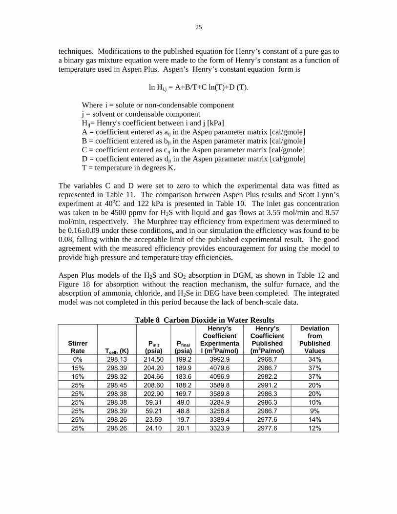
Reaction (2) is analogous to the Water Gas Shift reaction for making H2 from CO and H2O. In Table 7, we have found negligible COS production from this reaction. This could because either the kinetics are slow or the partial pressure of H2S is low. This is further illustrated by test plan CO + S, where all of the COS produced is immediately converted to hydrogen sulfide and carbon dioxide via Reaction (1). After this was realized, different concentrations of SO2 were introduced keeping all other conditions uniform. COS was produced via Reaction (2) unless an excess of SO2 was used. Once an excess of SO2 was used, CO2 was produced, indicating that either the reverse of Reaction (1) was taking place or that COS was being hydrolyzed. We will need to perform additional tests to verify these pathways. Task 2.5 – Tray Efficiency and Parameter Optimization – No significant activity due to the unavailability of the bench-scale unit. Task 3 – Computer Simulation Model – To confirm the accuracy of our test equipment and our simulation model, CO2 solubility in water at 25°C was measured and compared to literature values. The vapor-liquid mixture was kept in the equilibrium cell which is temperature and pressure controlled. The magnetic stirring device was used to enhance the attainment of equilibrium. The influence of the stirrer speed and the pressure was evaluated. Table 8 presents the results of the CO2 in water experiments. The pressure was kept low to study the effects of the stirrer, because it has been previously published that at pressures above 9 atm the interactions of the gas phase with the liquid phase changes the gas phase hydrodynamics too much. With increasing pressures, the deviation from the true Henry’s constant increased, as seen in Table 8. This is to be expected, as Henry’s Law accounts for a region that is not accounted for by Raoult's Law. Raoult's Law only works over the whole concentration range when the two compounds are almost identical; it generally also works well for the solvent in the region where the concentration of solute is low and the pressure is low. Although no thorough investigation was carried out, it is quite clear that the gas phase hydrodynamics change with pressure (density) as was also found by Versteeg. Through the experimental, as shown in Table 8, decreasing the pressure and increasing the stirrer rate was found to provide reproducible results closer to the fitted published data presented in Versteeg.

24
Table 7 Results of COS Experiments Reactor_out
Experiments Moles/hr Consumed (in-out) Output_Matl. Streams bal: N2
2a 0.04624 CO CO, H2S -0.02365 H2S
RXN: CO + H2S -->COS + H2 -0.00061 COS -0.00089 CO2
2b 0.04696 CO
CO; H2S; +Solvent 0.08267 H2S RXN: CO + H2S + Solvent -->COS + H2 0.00060 COS
-0.00123 CO2
3 0.01000 CO SO2, CO, H2S 0.03839 SO2(B)
RXN: SO2 + CO + H2S --> 0.03630 H2S -0.00023 COS 0.00026 CO2 0.04313 S
1a 0.01869 COS
COS; +Solvent -0.01632 CO2 RXN: COS + Solvent --> H2S + CO2 -0.01692 H2S
CO; +Solvent 0.05139 CO
RXN: CO + Solvent + S ---> -0.00002 H2S -0.00001 CO2 0.00000 COS 0.01188 S
3c 0.06604 CO
CO,H2S, SO2, +Solvent 0.06846 SO2 0.06286 H2S 0.00388 COS 0.15325 S
repeated 3c 0.06527 CO
CO,H2S, SO2, +Solvent 0.05406 SO2 0.06394 H2S 0.00004 COS -0.00036 CO2 0.12028 S
3d * 0.06604 CO
CO, H2S, 120%SO2, +Solvent 0.06567 SO2 0.06387 H2S 0.00031 COS -0.00119 CO2 0.06359 S
3d-1 -0.26644 CO
CO, H2S, 100%SO2, +Solvent 0.05769 SO2 0.06386 H2S -0.00001 COS -0.00060 CO2 0.106 S
A temperature dependant Henry’s Law constant for hydrogen sulfide and sulfur dioxide in diethylene glycol methyl ether (DGM) is given in literature and the values are presented in Table 9. Hydrogen sulfide solubility in DGM was measured and compared to the published results in Table 9 Agreement of hydrogen sulfide solubility in DGM to the experimental results of Scott Lynn at 25°C confirms our experimental and theoretical
25
techniques. Modifications to the published equation for Henry’s constant of a pure gas to a binary gas mixture equation were made to the form of Henry’s constant as a function of temperature used in Aspen Plus. Aspen’s Henry’s constant equation form is
ln Hi,j = A+B/T+C ln(T)+D (T).
Where i = solute or non-condensable component j = solvent or condensable component Hij= Henry's coefficient between i and j [kPa] A = coefficient entered as aij in the Aspen parameter matrix [cal/gmole] B = coefficient entered as bji in the Aspen parameter matrix [cal/gmole] C = coefficient entered as cij in the Aspen parameter matrix [cal/gmole] D = coefficient entered as dji in the Aspen parameter matrix [cal/gmole] T = temperature in degrees K.
The variables C and D were set to zero to which the experimental data was fitted as represented in Table 11. The comparison between Aspen Plus results and Scott Lynn’s experiment at 40oC and 122 kPa is presented in Table 10. The inlet gas concentration was taken to be 4500 ppmv for H2S with liquid and gas flows at 3.55 mol/min and 8.57 mol/min, respectively. The Murphree tray efficiency from experiment was determined to be 0.16±0.09 under these conditions, and in our simulation the efficiency was found to be 0.08, falling within the acceptable limit of the published experimental result. The good agreement with the measured efficiency provides encouragement for using the model to provide high-pressure and temperature tray efficiencies. Aspen Plus models of the H2S and SO2 absorption in DGM, as shown in Table 12 and Figure 18 for absorption without the reaction mechanism, the sulfur furnace, and the absorption of ammonia, chloride, and H2Se in DEG have been completed. The integrated model was not completed in this period because the lack of bench-scale data.
Table 8 Carbon Dioxide in Water Results
Stirrer Rate Tcell, (K)
Pinit (psia)
Pfinal (psia)
Henry’s Coefficient
Experimental (m3Pa/mol)
Henry’s Coefficient Published (m3Pa/mol)
Deviation from
Published Values
0% 298.13 214.50 199.2 3992.9 2968.7 34% 15% 298.39 204.20 189.9 4079.6 2986.7 37% 15% 298.32 204.66 183.6 4096.9 2982.2 37% 25% 298.45 208.60 188.2 3589.8 2991.2 20% 25% 298.38 202.90 169.7 3589.8 2986.3 20% 25% 298.38 59.31 49.0 3284.9 2986.3 10% 25% 298.39 59.21 48.8 3258.8 2986.7 9% 25% 298.26 23.59 19.7 3389.4 2977.6 14% 25% 298.26 24.10 20.1 3323.9 2977.6 12%

26
Table 9 Hydrogen Sulfide and Sulfur Dioxide Henry’s Constant Coefficients
Gases Ho21 Hsoln R H21 at 130 C
Solubility at 25 C
Solubility at 130 C
kPa/m.f. kJ/mol kJ/mol K kPa/m.f. mol/Kg Mpa mol/Kg MPa H2S 843.4 -16.16 0.008314 4614.03 9.87 1.80SO2 31.15 -37.13 0.008314 1546.07 267.19 5.38
Table 10 Henry’s Constant for Hydrogen Sulfide in DGM Results for
Experimental Set 0
Gas Temp (K) Pi (psia) Pf (psia) Hexp
(m3Pa/ mol)
H (Lynn@ 25°C, 1 atm) (m3Pa/ mol)
H2S(10%)/N2 298.19 29.0 23.5 109 101
H2S(10%)/N2 298.19 25.2 22.6 104 101
Table 11 Constants for Henry’s Law Equation
Gas
Temperature (K) A B
Aspen H(kPa)
Published Lynn
H2S 408 13.28 1948.74 4917.29 4894.65 SO2 408 18.47 4477.52 1789.58 1770.70
104
363
0.000SOLVENT104
363
1.000
FEED
104
363
1.000
PROD-GAS
104
363
0.000
PROD-LIQ
B2
Temperature (F)
Pressure (ps i)
Vapor Fracti on
2H2S + SO2 --> 1 .5 S2 + 2H2O
Figure 18 Aspen Plus Process Flow Diagram of Absorption Tower for UCSRP-HP

27
Table 12 Stream Results from Aspen Plus of Absorption Tower at a Temperature of 104°F and 362.6 psi
FEED PROD-
GAS PROD-LIQ SOLVENT Temperature, °F 104.0 104.1 104.1 104.0
Pressure, psi 362.6 362.6 362.6 362.6 Vapor Frac, 1.0 1.0 0.0 0.0
Mole Flow, lbmol/hr 1.1 1.1 0.5 0.5 Mass Flow, lb/hr 31.8 31.6 56.6 56.4
Volume Flow, cuft/hr 19.0 18.9 1.1 1.1 Enthalpy, MMBtu/hr 0.0 0.0 -0.1 -0.1
Mass Flow, lb/hr H2O 0.0 0.0 0.0 0.0 H2S 0.1 0.1 0.0 0.0
N2 31.7 31.5 0.1 0.0 SULFU-01 0.0 0.0 0.0 0.0
DGM 0.0 0.0 56.4 56.4 Task 4 – Techno-Economic Analysis –ConocoPhillips provided GTI with a confidential initial feed stream to the UCSRP-HP section of the plant. The balance assumed that the EGAS process would not have to remove chlorides and/or ammonia since it will be removed in the lower section of the absorber column. This simplifies their flow sheet. The stream temperature was up to 640°F. The design will recover the heat by cross-exchanging the feed and outlet streams to allow the UCSRP-HP to operate near the 300°F target conditions. GTI did not complete the techno-economic analysis during this period due to the lack of bench-scale data. When the data are available, the evaluation will be performed. Task 5 – Project Management and Reporting – GTI submitted the required monthly and annual reports to ICCI in a timely manner. Two papers and presentations were made on the subject of this project, namely: Matonis, D., Howard S. Meyer, and Dennis Leppin, “Desulfurization of High-Pressure Gasified Coal Using the UC Sulfur Recovery Process”, Presented at Twenty Third Annual International Pittsburgh Coal Conference, September 25 – 28, 2006, Pittsburgh, PA. Meyer, H. S., Diana Matonis, Dennis Leppin, and Scott Lynn, “UC Sulfur Recovery Process – Integrated Multi-Contaminant Removal Process for Coal-Derived, Warm Syngas Cleanup”, Presented at The 32nd International Technical Conference on Coal Utilization & Fuel Systems, June 10 – 15, 2007, Sheraton Sand Key, Clearwater, FL.
CONCLUSIONS AND RECOMMENDATIONS
The following conclusions were reached in this project:
o The UCSRP-HP process continues to be a viable technology that can significantly

28
simplify the clean up of coal-derived syngas. o A bench-scale test unit is being installed at GTI that will provide the necessary
data to scale-up the UCSRP-HP process to the next stage, a pilot plant. It offers the flexibility for testing with simulated as well as real coal-derived syngas.
o The solvent and catalyst used in the UCSRP-HP process are stable under the anticipated operating conditions.
o Carbon steel is an adequate material of construction for the process vessels, fittings, and piping. More expensive stainless steel is not required.
o The purity of the sulfur formed in the UCSRP-HP is 99.2% without any washing or other preparation procedures. The commercial target for sulfur purity is greater than 99.5%.
o Elemental mercury was removed down to 0.2 ppbw levels, well below the 5 ppbw target.
o The increased solubility of H2Se in the presence of ammonium chloride provides a good indication that the process will be able to remove selenium to the 0.2 ppmw target.
o Preliminary results indicate that COS formation can be controlled by excess SO2 in the gas. Any COS that does form will be soluble in the lean DGM solvent at the top of the column and brought back to the reaction zone where it will be exposed to fresh SO2.
o Aspen Plus model appears adequate for simulating the UCSRP-HP process. Based on the results from the current period, GTI recommends that additional laboratory work be performed under the following tasks. This project would complement work being performed for the US Department of Energy in their follow on program that includes laboratory and bench-scale testing of the UCSRP-HP with simulated and real coal-derived syngas. This is a critical step before the technology is ready for pilot plant testing. Task 1 – Laboratory Experiments Subtask 1.1 – Heavy Metal Removal – Heavy metals that can be in the syngas stream include selenium, mercury, cadmium, and arsenic. Selenium is expected to be in the form of H2Se while mercury is expected in the metallic form. The current testing showed the increased solubility of H2Se in DEG with the presence of ammonia chloride. We also showed mercury removal down to 0.2 ppb levels through a reaction with sulfur. In this subtask, GTI would investigate means to increase the heavy metal solubility and/or reactivity at 275-300°F and pressures from atmospheric to 400 psi. Task 1.2 – Ammonia and Halogen Removal – The purpose of this subtask is to understand the effect of water content and ammonia solubility on formation of NH4Cl as assumed for the removal of chlorides. The ammonia solubility may also affect the solubility of the heavy metals into the solvent system for removal. At least 2 other glycol ethers should also be tested to determine the impact of the solvent on absorption and reactivity.

29
Task 1.3 – Regeneration of DEG – In this subtask, the clean up system/chemistry for the DEG would be studied. Loadings would be determined in order to determine a reasonable regeneration scheme. This information would be modeled in Task 2 and used in optimization studies as part of Task 3. Task 1.4 – Trace Sulfur Removal – The objective of this subtask would be to complete the COS studies started in current project to estimate the ultimate cost of removal/converting COS from the feed gas. We have showed that by controlling the various reaction pathways, COS formation can be minimized or eliminated. This may require additional water or sulfur dioxide within the reactor to promote the WGS equivalent reaction to minimize the amount of COS in the product gas. Task 2 – Computer Simulation Model – Based on the data gathered during in the laboratory, the Aspen-Plus-based computer simulation model established in the current work would be modified and refined by GTI. The computer model would be used for the purpose of bench-scale data analysis, process optimization, and economic analysis in Task 3. The model would also be used for designing and planning of pilot-scale unit. Task 3 – Techno-Economic Analysis – In this task, GTI would use the results from the Task 1 testing and Task 2 computer simulation model to conduct a techno-economic evaluation of the process applied to syngas cleanup for a 500 MWe Illinois #6-coal-based IGCC power plant and for hydrogen production. GTI would use the economic case established by COP as the overall basis and modify the design and recalculate the economics.
30
DISCLAIMER STATEMENT
This report was prepared by Howard S. Meyer, Gas Technology Institute, with support, in part, by grants made possible by the Illinois Department of Commerce and Economic Opportunity through the Office of Coal Development and the Illinois Clean Coal Institute. Neither Howard S. Meyer, Gas Technology Institute, nor any of its subcontractors, nor the Illinois Department of Commerce and Economic Opportunity, Office of Coal Development, the Illinois Clean Coal Institute, nor any person acting on behalf of either: (A) Makes any warranty of representation, express or implied, with respect to the
accuracy, completeness, or usefulness of the information contained in this report, or that the use of any information, apparatus, method, or process disclosed in this report may not infringe privately-owned rights; or
(B) Assumes any liabilities with respect to the use of, or for damages resulting from
the use of, any information, apparatus, method or process disclosed in this report. Reference herein to any specific commercial product, process, or service by trade name, trademark, manufacturer, or otherwise, does not necessarily constitute or imply its endorsement, recommendation, or favoring; nor do the views and opinions of authors expressed herein necessarily state or reflect those of the Illinois Department of Commerce and Economic Opportunity, Office of Coal Development, or the Illinois Clean Coal Institute. Notice to Journalists and Publishers: If you borrow information from any part of this report, you must include a statement about the state of Illinois' support of the project.


