
CERSA-MCI53, parc Expobat13480 CABRIES
FRANCEtel: +33 (0)4 42 02 60 44
fax: +33 (0)4 42 02 79 79web: http://www.cersa-mci.com
email: [email protected], [email protected]
CIM. Cersa Instruments Manager.
User's manual.
Manual version : 3.0.0© 2012 CERSA-MCI

CIM. Cersa Instruments Manager. User's manual.2
© 2012 CERSA-MCI
Manual version : 3.0.0
Table of Contents
Part I CIM in your factory 4
................................................................................................................................... 51 Architecture
................................................................................................................................... 72 Production management
................................................................................................................................... 83 Supervisor
................................................................................................................................... 94 Required PC specifications
................................................................................................................................... 105 Quick start
Part II Interface 11
................................................................................................................................... 121 Main
......................................................................................................................................................... 13Line informations 1.1
......................................................................................................................................................... 14Connexions 1.2
......................................................................................................................................................... 16Measures and events 1.3
......................................................................................................................................................... 18Position target 1.4
......................................................................................................................................................... 19Production 1.5
.................................................................................................................................................. 20Measures graph1.5.1
.................................................................................................................................................. 23Events graph1.5.2
.................................................................................................................................................. 24X axis1.5.3
.................................................................................................................................................. 26X selection1.5.4
.................................................................................................................................................. 26Spool selection1.5.5
.................................................................................................................................................. 27Save selection1.5.6
.................................................................................................................................................. 28Selection report1.5.7
.................................................................................................................................................. 32Production controls1.5.8
......................................................................................................................................................... 35Explorer 1.6
.................................................................................................................................................. 36Measures graph1.6.1
.................................................................................................................................................. 37Events graph1.6.2
.................................................................................................................................................. 38X axis1.6.3
.................................................................................................................................................. 38Cursors1.6.4
......................................................................................................................................................... 39Scope manager 1.7
.................................................................................................................................................. 40Add scope1.7.1
.................................................................................................................................................. 41Select signal1.7.2
.................................................................................................................................................. 41Signal tab1.7.3
.................................................................................................................................................. 42Process tab1.7.4
.................................................................................................................................................. 43Scale tab1.7.5
.................................................................................................................................................. 44Display tab1.7.6
.................................................................................................................................................. 45Delete scope1.7.7
.................................................................................................................................................. 45Start stop scope1.7.8
.................................................................................................................................................. 45Refresh time1.7.9
.................................................................................................................................................. 45Save scopes1.7.10
.................................................................................................................................................. 46Save sequences1.7.11
......................................................................................................................................................... 48Measures manager 1.8
.................................................................................................................................................. 50Settings tab1.8.1
.................................................................................................................................................. 52Mix measure tab1.8.2
......................................................................................................................................................... 54Parameters manager 1.9
.................................................................................................................................................. 54Tolerances & Detection1.9.1
.................................................................................................................................................. 55Analog interface1.9.2

3Contents
Manual version : 3.0.0
.................................................................................................................................................. 56Digital interface1.9.3
.................................................................................................................................................. 57Measure1.9.4
.................................................................................................................................................. 58Informations1.9.5
................................................................................................................................... 592 Password
................................................................................................................................... 613 Load
......................................................................................................................................................... 62Production files 3.1
......................................................................................................................................................... 65Scope files 3.2
................................................................................................................................... 664 Key protection
................................................................................................................................... 675 About
................................................................................................................................... 686 Toolbox
......................................................................................................................................................... 69Export to CSV 6.1
................................................................................................................................... 727 Connexions manager
................................................................................................................................... 758 Lines manager
......................................................................................................................................................... 77Production configuration 8.1
......................................................................................................................................................... 78Data logging 8.2
......................................................................................................................................................... 79Start and stop production 8.3
......................................................................................................................................................... 81Product features 8.4
......................................................................................................................................................... 82Product specification 8.5
......................................................................................................................................................... 83Feature link 8.6
......................................................................................................................................................... 84Product order 8.7
................................................................................................................................... 859 Preferences
......................................................................................................................................................... 86Change password 9.1
................................................................................................................................... 8710 Touchpad panel
Part III Client databases 88
................................................................................................................................... 891 Database relationships
................................................................................................................................... 902 CIM product database
......................................................................................................................................................... 91TB_CIM_LINE_STATEMENT 2.1
......................................................................................................................................................... 92TB_FEATURE_CLASS 2.2
......................................................................................................................................................... 93TB_FEATURE_CLASS_EVENT_LINK 2.3
......................................................................................................................................................... 94TB_FEATURE_TYPE 2.4
......................................................................................................................................................... 95TB_FEATURE_TYPE_TOLERANCE_LINK 2.5
......................................................................................................................................................... 96TB_PRODUCT_TYPE 2.6
......................................................................................................................................................... 97TB_PRODUCT_SPECIFICATION 2.7
......................................................................................................................................................... 98TB_PRODUCT_ORDER 2.8
................................................................................................................................... 993 CIM report database
......................................................................................................................................................... 100TB_SPOOL 3.1
......................................................................................................................................................... 101TB_SPOOL_FEATURE_CLASS_EVENTS 3.2
......................................................................................................................................................... 102TB_SPOOL_FEATURE_CLASS_EVENTS_DETAIL 3.3
......................................................................................................................................................... 103TB_SPOOL_FEATURE_CLASS_STATISTICS 3.4

4
CIM. Cersa Instruments Manager. User's manual.
Part I: CIM in your factory
© 2012 CERSA-MCI
Manual version : 3.0.0
Part I: CIM in your factoryThis part explains the architecture of the complete CERSA offer for your production line, the onlyway for the: ”full inline quality certification”.
Our offer integrates:
· Measurement instruments for fiber optics: o LIS-G for Glass fiber diameter, spinning, non-circularity measurement and defect detection
(including airline).o NCTM for Glass fiber drawing tension measurement.o CM5 for Coated fiber diameter, asymmetry measurement, and Lump & Neck detection.
· Production software:o C.I.M. software (CERSA Instruments Manager) is a PC environment that manage all
CERSA-MCI instruments. It provides a complete set of comprehensive tools to improve andmaster the production process as well as all features to certify the whole productionspecifications in line.
Main features
· Monitoring the process in real time.· Data logging.· Production reports (Statistics).· Instruments configuration.

5
Part I: CIM in your factory
Manual version : 3.0.0
Architecture
Architecture1
CERSA architecture
6
CIM. Cersa Instruments Manager. User's manual.
Part I: CIM in your factory
© 2012 CERSA-MCI
Manual version : 3.0.0
Architecture
Cersa instruments are located at different positions of your production line. They measure allthe critical parameters for your process. CIM connects all the line's instruments together (connexions), in order to have a global graphical view of all these parameters in real time.
CIM can also centralize several external voltage signals like furnace temperature, coatingpressure, speed, in order to show those measures in the same charts as CERSA measures.These external signals need to use an analog to digital converter (ADC). (This functionality isnot yet available).
However, all the instruments need to have a synchronization with your process. Using yourreset and length counting signals each instrument have the capability to locate all defectsaccurately with the same reference as your process control system. Thus CIM interface givesthe necessary information to help the user in the product rejection process. Your process controlsystem can access to some critical parameters directly using instruments BNC outputs.
Our customers have the capability to define specifications for each product used in their factory(CIM_PRODUCT database). These specifications can be global to the factory or specific toseveral lines. In this way an external database order or manual operator action can order theproduction in lines resulting in an automatic configuration of tolerances and specifications to theinstruments.
All the results of your production can be stored spool by spool in distant or local database (CIM_REPORT database). This report can be global to the factory or specific to several lines.Thus our customers have all necessary information to qualify and certify whole spools.
In addition to these data logging functions, you can save your production in CIM proprietary file.These file store the full information for your batch production. Statistical reports can begenerated.
All the tools included in CIM software help the process engineer and operators to master therelations of causes and effects between all the measured parameters. It is a global solution forsupervision, data logging and quality reports.

7
Part I: CIM in your factory
Manual version : 3.0.0
Production management
Production management2
Production management
The chart-flow above presents the production management used by CIM software in order tomake the following actions:
· Database report.· Configure instrument tolerances.· Configure batch name and product type.· Save batch data in file.· Reset CIM display.

8
CIM. Cersa Instruments Manager. User's manual.
Part I: CIM in your factory
© 2012 CERSA-MCI
Manual version : 3.0.0
Supervisor
Supervisor3
Under development
The CIM supervisor is a PC software that communicates with all production lines. It summarizesin real time the basic information for each line. It gives you the capability to supervise all yourlines from desk.
Using this software hosted on one PC, you will be able to watch in real time the status of thewhole production. You access to all data that are hosted by the child’s PCs. You also are able towatch the details, like real time charts line by line. You can see the previous production using a
browser that helps you to select the records by date.

9
Part I: CIM in your factory
Manual version : 3.0.0
Required PC specifications
Required PC specifications4
The minimum requirements are defined below:
· Windows XP service pack 2 has been validated. Windows seven is under validation.· 2 GB RAM.· Dual core processor 2GHz.· 250 Gb hard disc with high speed access.· Graphical card with 256 MB ram.· 1280x1024 Screen. (Lower resolutions will reduce the ergonomics)· 1 RS232 serial link port for each connected instrument.
Remarks:· If your computer doesn't have RS232 port, you can use additional internal boards (USB to
RS232 converters are not recommended).· CIM interface is completely compatible with touch screen displays. · CIM is compiled for 32-bits target. The 64-bits target is not validated yet.· If you use data logging, configure network and user permissions of path containing central
databases.

10
CIM. Cersa Instruments Manager. User's manual.
Part I: CIM in your factory
© 2012 CERSA-MCI
Manual version : 3.0.0
Quick start
Quick start5
The following steps will assist you in the setup of global CERSA offer in your factory.
Install instruments (See instrument manual for more details)
· Fix the instruments in line.· Plug in air supply for the instrument if necessary.· Connects digital input output instrument interface with your process control system.· Connects BNC analog outputs with your process control system.· Connects RS232 instrument interface with the PC.· Keep in mind the PC COM port used for every instrument.· Plug in power supply for the instrument.
Install CIM
Your instrument has been delivered with CERSA-MCI CD-ROM including the CIM Setup file.When you insert your CD-ROM in your drive, an automatic setup is launched.
Remark:
· If the setup is not launched automatically you need to launch the setup manually from youdrive at the following location: Drive:\CIM\setup.exe
Follow step by step the setup procedure displayed on the screen.
Protection key
Plug in the USB protection dongle to benefit the full production features. Refer to key protection.
Configure CIM
· Launch CIM software.· Enter the "supervisor" password.· Add your connexions (CERSA instruments) in the connexions manager interface.· Configure the name of your line, database and data logging options in lines manager
interface.· Define your products specifications in lines manager interface.

11
Part II: Interface
Manual version : 3.0.0
Part II: InterfaceThe main control panel is the first interface displayed when you launch CIM software. It containsglobal functions to manage your production, configure the software and read recorded data.These functions are displayed according to the access level of the current user. Thus the basicproduction functions are available for the operators but advanced configuration functions areavailable only for supervisors.
See password topic for more information about user access level.
Main control panel
It can be accessible from other panels by click on the following icon:
Main control panel button

12
CIM. Cersa Instruments Manager. User's manual.
Part II: Interface
© 2012 CERSA-MCI
Manual version : 3.0.0
Main
Main1
Main panel button
By clicking on the main button, user has access to production lines controlled by the software.
Main panel
This panel is available when at least one connexion has been added with connexions managerinterface. The right side of this interface display real time information in "Lite view" tab (for mainmeasures) and in "Full view" tab for the whole measures. Thus for each line are displayed the following zones allowing the user to manage the lineproduction:
· Line informations.· Connexions.· Measures and events.· Position target (Only in lite view).· Production.· Explorer.· Scope manager (accessible only with supervisor level).· Measure manager (accessible only with supervisor level).· Parameters manager (accessible only with supervisor level).
At the bottom of the main screen, the control panel button display multiple functions specifics foreach zone.
Control panel button

13
Part II: Interface
Manual version : 3.0.0
Main
Line informations1.1
Production status
Gives the status of the line production.
Production On: the conditions to begin the production are met refer to Lines manager.
Production Off: at least one condition is not respected.
Batch name
The name of the produced batch or preform.
Product name The kind of product that is currently produced. Product specifications are defined in Linesmanager interface.

14
CIM. Cersa Instruments Manager. User's manual.
Part II: Interface
© 2012 CERSA-MCI
Manual version : 3.0.0
Main
Connexions1.2
Connexions table
This table displays the status for each connexion belonging to the line. The first column display connexions names linking the instrument name and serial number. The second column display short name for the instrument error codes. Refer to the instrumentmanuals for more information about error codes.The third column displays icon which represents the status of the connexion.
Connexion status icons
The status of connexion is defined by the following list:
Connexion run icon: The connexion is running without problem.
Connexion break icon: The main communication is not enabled for this connexion.
Connexion identification icon: CIM identifies connexion.
Connexion reconfiguration icon: CIM reconfigures several parameters in connexion.
Connexion clear events icon: CIM clears events in instruments.
Connexion reset line icon: Connexion has been reset in order to reset line.
Connexion disconnected icon: Connexion is disconnected.
Connexion start stop error icon: Problem to start or stop COM port.

15
Part II: Interface
Manual version : 3.0.0
Main
Connexion process icon: The connexion processes parameters.
Connexion comm error icon: Communication error.
Connexion compreg error icon: This error appears when the user changes parameter and the requested valueis not the same as the value stored by the instrument.
Warning icon: The instrument sends an error code.

16
CIM. Cersa Instruments Manager. User's manual.
Part II: Interface
© 2012 CERSA-MCI
Manual version : 3.0.0
Main
Measures and events1.3
Measures table
This table shows in real time all the measures and related events of the instruments belongingto the line. When out of tolerance is detected in measure an event is reported in third column of this table.
Out of high tolerance icon.
Out of low tolerance icon.
The display refresh time of this table is about one second. The name of each measure can beset in measures manager and it is prefixed by connexion prefix defined in connexions manager.
Remark about events:
It is a particular phenomenon that is detected by the instrument. Events are detected in real timeby the measurement system, it is dated and located (length). It is also characterized in term ofextremum value.
Here below is an example of high speed diameter fluctuation which exceeds the tolerances.

17
Part II: Interface
Manual version : 3.0.0
Main

18
CIM. Cersa Instruments Manager. User's manual.
Part II: Interface
© 2012 CERSA-MCI
Manual version : 3.0.0
Main
Position target1.4
Position target
This graph displays the position of the customer product when position X-Y measures aretransmitted by the instrument.
Please refer to the instrument manual for the instrument alignment.

19
Part II: Interface
Manual version : 3.0.0
Main
Production1.5
Production zone
In order to study in detail your production, this interface gives you the possibility to manage eachmeasure independently of others.
The events generated by the instruments are located independently for each measure. They arepositioned with high precision according to the time or length.
When the production zone is displayed the control panel shows the following functions:
Production control panel

20
CIM. Cersa Instruments Manager. User's manual.
Part II: Interface
© 2012 CERSA-MCI
Manual version : 3.0.0
Main
Measures graph1.5.1
Production measures graph
On this graph are drawn continuously the measures coming from the instruments belonging tothe line. The display refresh time of the measures is about one second.
Because CIM displays information for complete batch, the original displayed data and resolutioncan change over the time in order to preserve processor resources. The original information isstored in internal file and can be restored with explorer functions.
All the line measures displayed in this graph are overlapped, but the displaying scale for eachmeasure can be managed independently. The Y axis of each measure can be displayed in theleft part of the graph.
Current Y axis
To change the measure to display in current Y axis, click or touch the corresponding cell in themeasures axis table.
Measures axis table
Min and max correspond to the minimal and maximal values of the measures graph. They arecomputed with amplitude and offset fields:
minimal value offset - (amplitude / 2)maximal value offset + (amplitude / 2)

21
Part II: Interface
Manual version : 3.0.0
Main
Amplitude and offset fields
To change the default values of the amplitude and offset for each measure, please refer tomeasures manager zone. To temporary change the amplitude and offset values of eachmeasure, please use graph settings button in control panel.
Graph settings button
Graph settings button displays the following interface panel. It can be also launched by rightclick in current Y axis and in measures axis table.

22
CIM. Cersa Instruments Manager. User's manual.
Part II: Interface
© 2012 CERSA-MCI
Manual version : 3.0.0
Main
Graph settings panel
This panel allows the user to modify settings for specific measure. All these changes can berestored to the default settings defined in measures manager interface.
To choose the measure to modify, click or touch the corresponding cell in the measures axistable. For each measure the following settings are available:
Y zoom
Y zoom button
Push this button to activate Y zoom functionalities. When Y zoom is active Y offset function isautomatically deactivated. To make "zoom in" of related measure slide up your finger (or clickand slide with mouse cursor) in Y axis. To make "zoom out" slide down your finger.
Y offset
Y offset button
Push this button to activate Y offset function. When Y offset is active Y zoom function isautomatically deactivated. To change the offset of related measure slide up your finger (or clickand slide with mouse cursor) in Y axis.
Amplitude
This numeric control allows the user to enter a value for amplitude of measure. This action isequivalent to Y zoom function.
Offset

23
Part II: Interface
Manual version : 3.0.0
Main
This numeric control allows the user to enter a value for offset of measure. This action isequivalent to Y offset function.
Display
Allows the user to display or not measure in measures graph. When the measure is notdisplayed, the label text for this measure appears with strikeout text.
Not displayed / displayed icons
Restore measure
Restore measure button
Restore default settings for selected measure in terms of amplitude and offset.
Restore all
Restore all button
This function restores the settings for all measures displayed in the measures graph.
Events graph1.5.2
Events graph
On this graph are displayed in real time the events coming from the instruments belonging to theline.
Two types of events are displayed in this graph:
· Segment event is used to display measure out of tolerances. · Point event is used to notify instrument alarms.
These events are displayed with the real duration and length. Refer to Measures and eventstopic for more details.
Because CIM displays information for complete batch, the original displayed data and resolutionchange over the time in order to preserve processor resources. The original information isstored in internal file and can be restored with explorer functions.
To define the position for events displayed in this graph please refer to measures manager.

24
CIM. Cersa Instruments Manager. User's manual.
Part II: Interface
© 2012 CERSA-MCI
Manual version : 3.0.0
Main
X axis1.5.3
X axis
The X axis is the reference axis used by measures graph and events graph for displaying. It canbe vertical moved with the X axis scroll button, this action resizes the measures graph and theevents graph zones.
X axis scroll button
In order to change the references and the mode of this axis you can click in reference settingsbutton or right click in the X axis. This action displays the reference settings panel.
X reference button
Reference settings panel
The following popup menu will appear by pressing X mode menu.
X mode menu
Two displaying modes are available.
Automatic mode
The whole batch is displayed in the graphs.
Current mode
Displays the last n minutes or meters. n is adjustable by the following actions:
· Slide right over the X axis to decrease the amount of displayed data.· Slide left over the X axis to increase the amount of displayed data.· By changing the value in the "current interval" interface.

25
Part II: Interface
Manual version : 3.0.0
Main
The selected mode is displayed in the X mode text box.
X mode text mode
The following popup menu will appear by pressing X reference menu.
X reference menu
Four references are available:
· Absolute PC time: displayed in hours:minutes:seconds day/month/year format. This time isdated by the computer.
· Relative PC time: elapsed time since the begin of the batch displayed in hours:minutes:seconds format. This time is dated by the computer.
· Batch time: elapsed time since the begin of the batch displayed in hours:minutes:secondsformat. This time is dated by the instruments.
· Batch length: produced length since the begin of the batch displayed in meters. This lengthis computed by the instruments.
We strongly recommend to use batch length mode. This mode needs reset and length countingsignals.
The selected reference is displayed in the X reference text box.
X reference text box
The restore button action comes back to default settings defined in line manager interface.

26
CIM. Cersa Instruments Manager. User's manual.
Part II: Interface
© 2012 CERSA-MCI
Manual version : 3.0.0
Main
Restore button
X selection1.5.4
X selection button
Push this button in the control panel to enable or disable the X selection function.
When the X selection function is enabled spool selection is deactivated and the user can makeselection by clicking twice in measures graph.
· The first click defines the start point of selection and displays a blue line.· The second click defines the stop point and display grayed zone. · This grayed zone represents the selection.
X selection preview
This functionality is necessary to explore, save in files and make reports of sections in yourproduction.
Spool selection1.5.5
Spool selection button
Push this button in the control panel to enable or disable the spool selection function.
When the spool selection function is enabled X selection function is deactivated and the usercan make spool selection by clicking in measures graph.
· The spool number is displayed by left clicking or touching the graph in related spool zone. · The spool number is refreshed if the user holds the finger or the mouse button while sliding.· When the user releases the button or the screen the spool zone is automatic selected.

27
Part II: Interface
Manual version : 3.0.0
Main
X selection preview
This functionality is necessary to explore, save in files and make reports of sections in yourproduction
Save selection1.5.6
Save selection button
Push save selection button to record data selection in file.
Save file panel
The user can choose the file name and target directory. The preview field displays the final path.
The extension of this kind of file is ".cimprd". The recorded file can be opened with load function

28
CIM. Cersa Instruments Manager. User's manual.
Part II: Interface
© 2012 CERSA-MCI
Manual version : 3.0.0
Main
located in main control panel.
Selection report1.5.7
Selection report button
Push selection report button in the control panel to display a report of your selection.
Report selection example
The report interface has four zones:
Informations
This table contains general informations about selection.
Informations zone
· Spool: spool number to which the selection belongs. · Length: length of selection in meters.· Start date time: the start time of selection in Year-Month-Day Hours:Minutes:Seconds
format.· Stop date time: the stop time of selection in Year-Month-Day Hours:Minutes:Seconds format.· Product name: the name of product defined in line manager with product specification
interface.· Line name: the name of the line in which selection was made.· Batch name: the name of the batch in which selection was made.

29
Part II: Interface
Manual version : 3.0.0
Main
Statistics
Statistics tab
This table shows for each measure:
· Measure name: the unit of measure is indicated in brackets.· Error: percentage of wrong measures in selection for every type of measure.· Cp and Cpk: process capability:
m = Nominal value.USL = Upper set limit. Related to the high tolerance.LSL = Lower set limit. Related to the low tolerance.µ = Average.s = Standard deviation.
· Average:
xi = Data set.n = number of measures.
· Standard deviation:
· Minimal value: minimal value in selection.· Maximal value: maximal value of selection.
Remark:· A measure is considered as wrong when it is out of tolerances or when an instrument alarm

30
CIM. Cersa Instruments Manager. User's manual.
Part II: Interface
© 2012 CERSA-MCI
Manual version : 3.0.0
Main
exists.
Events
Events tab
Shown in this table is the number of cumulated events found in the selection. For each measureare indicated:
· Event: the name of the related measure. The unit of event is indicated in brackets.· Event type: out of "high tolerance" or out of "low tolerance".· Number of events.
Event detail
Event detail tab
This table contains the detail for each event found in selection.

31
Part II: Interface
Manual version : 3.0.0
Main
· Event: name of the related measure. The unit of event is indicated in brackets.· Event type: out of high tolerance or out of low tolerance.· Extremum value: if high tolerance this value represents the maximum value of the event. If
low tolerance this value represents the minimum value of the event.· Spool time: the time when the event occurred. This time is relative to the beginning of the
spool.· Duration: the duration of event in seconds.· Spool position: the position of the event in meters. This position is relative to the beginning
of the spool. · Length: the length of event in meters.
All these tables can be printed to make paper reports by click on print button.
Print button
The "select print settings window" allows the user to select regions to print and the printer touse.
Select print settings window
The following regions can be selected:
· Explorer panel.· General information table.· Statistics table.

32
CIM. Cersa Instruments Manager. User's manual.
Part II: Interface
© 2012 CERSA-MCI
Manual version : 3.0.0
Main
· Events table.· Event detail table.
Production controls1.5.8
Production controls button
Press this button in the control panel to display the production controls.
Production controls panel
Reset
Reset button
This button performs a general reset for the current batch produced in corresponding line.This action deletes all measures, events and spool information. It is not available whenproduction is started. See Lines manager chapter for more details about production.
Change spool
Change spool button
Press change spool button to send reset order for all instruments belonging to the line. Spoolreset is represented by a vertical green line in production zone.

33
Part II: Interface
Manual version : 3.0.0
Main
Reset line in production graphs
This action is only available when production is started. See Lines manager chapter for moredetails about production.
Set batch
Set batch button
By pressing this button the "New production selection" interface appears. This interface allowsthe user to enter batch name and the type of product. Product configuration is defined in linesmanager interface.
New production panel
Force start prod

34
CIM. Cersa Instruments Manager. User's manual.
Part II: Interface
© 2012 CERSA-MCI
Manual version : 3.0.0
Main
Force start production button
This action forces start production even if start conditions are not respected. See more detailsabout start conditions in lines manager chapter.
Force stop prod
Force stop production button
This action forces stop production even if stop conditions are not respected. When production isended CIM will scan order of production to initialize production (only in external productconfiguration). See more details about stop conditions in lines manager chapter.

35
Part II: Interface
Manual version : 3.0.0
Main
Explorer1.6
Explorer zone
This interface is automatically displayed when a valid selection is defined and the user clicks onthe explorer button. It is useful to analyse specific part of your production.
Explorer button
CIM restores original data corresponding to the selection and displays automatically theinformation in this interface. All the displayed measures and events can be tracked with cursorsin order to give the detail of your production.When the selection is too large the resolution status zone displays "Low resolution" message. Inorder to display the data with full resolution the user can override the selection with X selectionand Explorer buttons. The user can come back to original selection using the restore selectionbutton.
Restore selection button
Save selection, Selection report, Graph settings and Reference settings can be used in thesame way as explained in Production chapter.
When the explorer zone is displayed the control panel shows the following functions
Explorer control panel

36
CIM. Cersa Instruments Manager. User's manual.
Part II: Interface
© 2012 CERSA-MCI
Manual version : 3.0.0
Main
Measures graph1.6.1
Measures graph
In this graph are displayed the measures of the selection. The settings for each measure can bemanaged in the same way as in production measures graph with the graph settings button.
To track the measures the user can touch or click on this graph. The measures table shows themeasures corresponding to the relative reference position of the vertical cursor.
Measures table
The values of this table remain unchanged while the cursor did not snap on another measure.

37
Part II: Interface
Manual version : 3.0.0
Main
Events graph1.6.2
Events graph
In this graph are displayed the events corresponding to the selection. To display the details for aspecific event, click or touch the event on the graph. Then the cross cursor will snap at line starton the nearest event. The details are displayed in the event detail table. When the selection does not contain the event start, stop or when the resolution of the selectionis not sufficient, the event table displays "unavailable".
Event detail table
The following informations are listed:
· Instrument type and serial number: is the connexion identifier of instrument that sends theevent to CIM.
· Event name and event type: the name of the measure in which the event occurs. Event typedisplays out of tolerances or alarms. See production events graph topic for more details.
· Argument start: used only for CERSA-MCI test configuration.· Argument stop: for out of tolerances events, the argument corresponds to the extrema
value. For status events it gives an additional internal information.· Spool: the spool number in which the event was located.· Spool time: the time in Hours:Minutes:Seconds format when the event occurs from the
beginning of the spool.· Duration: the duration of event in seconds. (Only for out of tolerances events. See production
events graph topic).· Spool position: the event position in meters from the beginning of the spool.· Length: the length of event in meters. (Only for out of tolerances events. See production
events graph topic).· PC time: time on which event occurs dated by PC in Hours:Minutes:Seconds format.· Batch time: the time in Hours:Minutes:Seconds format when the event occurs from the
beginning of the batch.· Batch position: the event position in meters from the beginning of the batch.
Please refer to your instrument manual to have the list of events and their description.

38
CIM. Cersa Instruments Manager. User's manual.
Part II: Interface
© 2012 CERSA-MCI
Manual version : 3.0.0
Main
X axis1.6.3
X axis
The X axis is the reference axis used by measures graph and events graph. The X referencecan be selected in control panel with X reference button. See more details about references inproduction X axis.
X reference button
The explorer X axis can be sliding at right to "X zoom in" around the vertical cursor and left to"X zoom out" around the vertical cursor.
Cursors1.6.4
Vertical cursor
Vertical cursor previex
This cursor allows to track measures in order to display information in explorer measures table.
Click on the measures graph and slide cursor to track the measures. The cursor snaps on thenearest measure when is released. The vertical cursor is displayed also in events graph to showcorrelation between events and measures but it can not be controlled by clicking in explorerevents graph.
This cursor is used also to give reference to makes X zoom function (See explorer X axis topicfor more details). When the user make "X zoom in" or X zoom out" the data is first refocusedaround the vertical cursor and then zoomed at the position of cursor. Cross cursor
Cross cursor preview
This cursor allows to track events displaying information in explorer event detail table.
Click on events graph as nearest as possible of event, to make the cursor snap on it. Becauseevents can be positioned by CIM with very high precision, several events can be displayedcloser. We recommend to use zoom function to place cursor with more precision.

39
Part II: Interface
Manual version : 3.0.0
Main
Scope manager1.7
Scope manager zone gives the capability to make the acquisition of CERSA instruments internalsignals and displaying it in scope interface. User can add several scopes interfaces in order tomake correlations between signals.
To add scope interface push add button in control panel. Then the following interface isdisplayed:
Scope interface
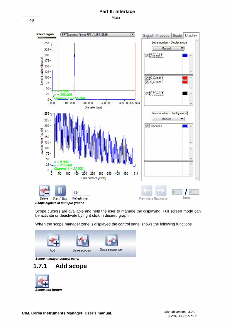
Each scope interface can display several synchronous signals in different channels and/or indifferent graphs.
Scope signals in multiple channels
40
CIM. Cersa Instruments Manager. User's manual.
Part II: Interface
© 2012 CERSA-MCI
Manual version : 3.0.0
Main
Scope signals in multiple graphs
Scope cursors are available and help the user to manage the displaying. Full screen mode canbe activate or deactivate by right click in desired graph.
When the scope manager zone is displayed the control panel shows the following functions
Scope manager control panel
Add scope1.7.1
Scope add button

41
Part II: Interface
Manual version : 3.0.0
Main
This button adds scope interface in scope manager zone. The new scope is positioned just afterthe last added scope.
Select signal1.7.2
Select signal menu
This ring control shows the available signals for instruments belonging the line. The list herebelow shows several examples:
· CCD diffraction· Real time diameter interferometry· Real time tension· Spinning evolution· Vibration FFT
For more details about configuration of signals please refer to instrument manuals.
Signal tab1.7.3
Signal tab
In this tab are displayed result controls (blue color) and parameters controls (green color) toconfigure signals correlated with scopes. Parameter controls can be adjusted only when scopeacquisition is stopped otherwise controls are dimmed.

42
CIM. Cersa Instruments Manager. User's manual.
Part II: Interface
© 2012 CERSA-MCI
Manual version : 3.0.0
Main
Process tab1.7.4
Process tab
In this tab user can select the signal processing to apply over the signal. Export to BMP button is active only for two dimensional signals.
Export to BMP button
Signal is displayed in blue color and the signal process is displayed in red color. Here below isshow one example of scope with FFT signal processing.
Scope "FFT diameter airline" example with FFT signal processing

43
Part II: Interface
Manual version : 3.0.0
Main
Scale tab1.7.5
Scale tab
This tab allows the user to change the scale mode of X and Y axis.
Scale mode axis
Three scales modes are available for each axis:
· Default: the instrument chooses the scale to display. · Automatic: CIM seeks minimal and maximal values and displays the signal regarding these
values.· Manual: user can change manually the minimal and maximal values for each axis.

44
CIM. Cersa Instruments Manager. User's manual.
Part II: Interface
© 2012 CERSA-MCI
Manual version : 3.0.0
Main
Display tab1.7.6
Display tab
In this tab the user can manage channels and cursors related to the scope.
Channels and cursors
The number of channels and cursors are defined by the instrument.
Two display modes are available:
· Default: The instrument chooses the channels, cursors and colors for displaying. · Manual: The user can choose the channels, cursors and colors for displaying.
The cross cursor legend displays the X and Y position of the cursor related to the graph scale.This cursor also gives the value of the nearest point related to the selected channel.

45
Part II: Interface
Manual version : 3.0.0
Main
Delete scope1.7.7
Delete scope button
This button delete scope interface.
Start stop scope1.7.8
Start stop button
This button starts and stops acquisition of signals from the instrument. To configure the scopeyou first have to stop the acquisition.
When you quit the scope manager zone, the acquisition of all scopes are automatically stopped.The acquisition will be restarted when you come back to the scope manager zone.
Refresh time1.7.9
Refresh time numeric control
This parameter defines the acquisition and display period expressed in seconds. Therecommended value for this parameter is one second. Smaller values can be applied to thisparameter but this action will use more resources.
Save scopes1.7.10
Scope save scopes button
By pushing this button, the user will be able to store in one single file all scope interfacesdisplayed in scope manager zone. The following interface will appear to locate and name thefile.

46
CIM. Cersa Instruments Manager. User's manual.
Part II: Interface
© 2012 CERSA-MCI
Manual version : 3.0.0
Main
Save file panel
The extension of this kind of file is ".cimscp". The recorded file can be open with load functionlocated in main control panel.
Save sequences1.7.11
Scope save sequence button
With this function you will be able to save sequence of displayed signals during a time period inone single file. You must enter the number of seconds that you want to record in the followinginterface.
Save sequence panel
Then the recording will run automatically. The following interface will appear at the end of recordto locate and name the file.

47
Part II: Interface
Manual version : 3.0.0
Main
Save file panel
CERSA can request you to send several signals in one single file to have a good statistic view ofyour process. This kind of tool is necessary in order to help you for advanced settings andimprove your measurement.
The extension of this kind of file is ".cimscp". The recorded file can be open with load functionlocated in main control panel.

48
CIM. Cersa Instruments Manager. User's manual.
Part II: Interface
© 2012 CERSA-MCI
Manual version : 3.0.0
Main
Measures manager1.8
Measures manager zone
This interface gives the possibility to transmit (RS232 communication), display and configuremeasures and events from the instruments belonging to the line. All available measures foreach instrument are displayed in "select transmitted measures" table.
The following icons define the status of the measure:
The selected measure or event is always transmitted. User cannot delete or add from current configuration.
The selected measure or event is transmitted.

49
Part II: Interface
Manual version : 3.0.0
Main
The selected measure or event is not transmitted.
Any change in the user configuration requires a reset in the line. The following messageappears to prevent the user that all the data will be lost:
Reset line message
Add measure
Add measure button
Add the selected measure to the current user configuration.
Delete measure
Delete measure button
Delete selected measure from current user configuration.

50
CIM. Cersa Instruments Manager. User's manual.
Part II: Interface
© 2012 CERSA-MCI
Manual version : 3.0.0
Main
Settings tab1.8.1
Settings tab
When the user selects a transmitted measure, this interface displays its settings and gives thepossibility to change the current configuration. When a non transmitted measure is selected thisinterface is dimmed.
The following settings are displayed:
Default name
Is the default CERSA name followed by the serial number of the instrument. This default namecannot be duplicated and is located at the top left of the settings tab interface.
General settings
· Name: This control displays and gives the possibility to change the user measure name. Thisname will be used in all the software interface.
· Color: This control displays and gives the possibility to change the user measure color. Thiscolor will be used in all the software interface.
· Display: This control displays or hides the measure (and measure event if exist) in measuresgraph, measures axis table, measures table and events graph.
51
Part II: Interface
Manual version : 3.0.0
Main
Not displayed / displayed icons
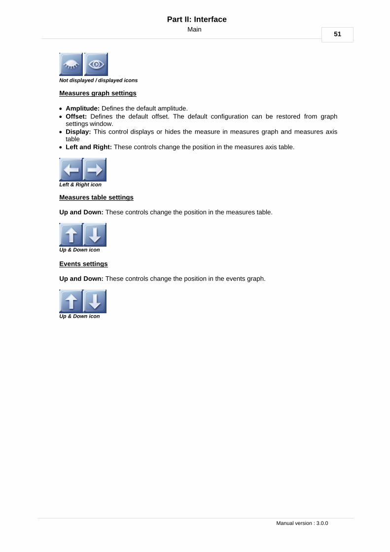
Measures graph settings
· Amplitude: Defines the default amplitude.· Offset: Defines the default offset. The default configuration can be restored from graph
settings window. · Display: This control displays or hides the measure in measures graph and measures axis
table· Left and Right: These controls change the position in the measures axis table.
Left & Right icon
Measures table settings
Up and Down: These controls change the position in the measures table.
Up & Down icon
Events settings
Up and Down: These controls change the position in the events graph.
Up & Down icon

52
CIM. Cersa Instruments Manager. User's manual.
Part II: Interface
© 2012 CERSA-MCI
Manual version : 3.0.0
Main
Mix measure tab1.8.2
Mix measure tab
This interface will add or delete measure that will be computed using existent transmittedmeasures. This capability is called "Mix measure".
To mix measures follow the next steps:
· Select function to compute the new mix measure from the following list.

53
Part II: Interface
Manual version : 3.0.0
Main
· Choose A and B measure by pressing, drag and drop from transmitted measures.
Add measure to mix
· Enter coefficients when the function uses these coefficients.· Finally add mix measure with the following button:
Add mix measure button
· To delete mix measure select the measure and click on delete mix measure button.
Delete mix measure button

54
CIM. Cersa Instruments Manager. User's manual.
Part II: Interface
© 2012 CERSA-MCI
Manual version : 3.0.0
Main
Parameters manager1.9
Parameters manager gives for each instrument belonging to the line the following interfacestructure:
· Tolerances & Detection· Analog interface· Digital interface· Measure · Informations
Tolerances & Detection1.9.1
Tolerances tab
This interface allows user to configure tolerances and detection parameters of instruments.Each measure or detection feature displays their tolerances in individual subregion tab. When the measurement value is outside the range, defined by the tolerances, the instrumentgenerates an event. These events are displayed in events graph.
The following configurations can generate events:
Measure > Nominal tolerance + Warning high tolerance EVENT WARNING HIGH (Notavailable yet)
Measure < Nominal tolerance - Warning low tolerance EVENT WARNING LOW (Notavailable yet)
Measure > Nominal tolerance + Out high tolerance EVENT OUT HIGHMeasure < Nominal tolerance - Out low tolerance EVENT OUT LOW
Please refer to the instrument manual for more details about configuration of tolerances.
55
Part II: Interface
Manual version : 3.0.0
Main
Analog interface1.9.2
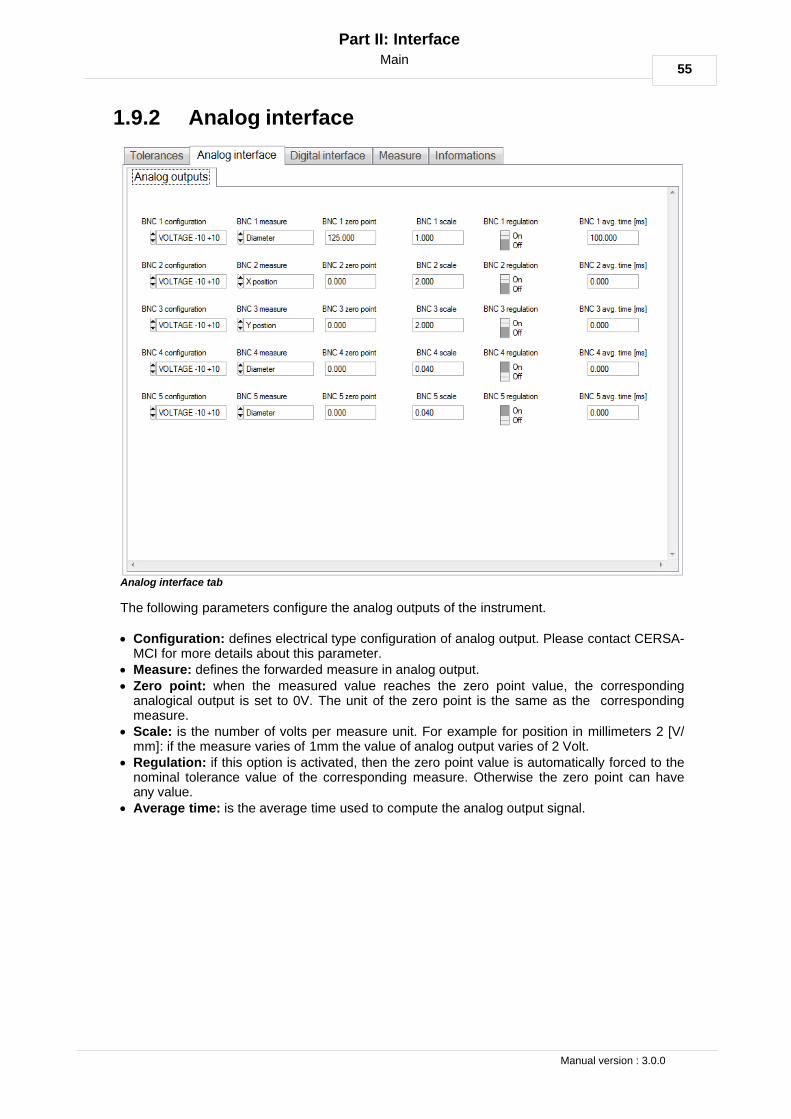
Analog interface tab
The following parameters configure the analog outputs of the instrument.
· Configuration: defines electrical type configuration of analog output. Please contact CERSA-MCI for more details about this parameter.
· Measure: defines the forwarded measure in analog output.· Zero point: when the measured value reaches the zero point value, the corresponding
analogical output is set to 0V. The unit of the zero point is the same as the correspondingmeasure.
· Scale: is the number of volts per measure unit. For example for position in millimeters 2 [V/mm]: if the measure varies of 1mm the value of analog output varies of 2 Volt.
· Regulation: if this option is activated, then the zero point value is automatically forced to thenominal tolerance value of the corresponding measure. Otherwise the zero point can haveany value.
· Average time: is the average time used to compute the analog output signal.

56
CIM. Cersa Instruments Manager. User's manual.
Part II: Interface
© 2012 CERSA-MCI
Manual version : 3.0.0
Main
Digital interface1.9.3
Digital interface tab
This tab contains two subregions in order to configure the digital interface of the instruments.
Digital input/outputs
This subregion allows user to configure input/outputs signals. The following configurations aregenerally used to give or receive a reference, event, alarm or status:
· UNAVAILABLE (not exist in the current instrument)· INPUT· OUTPUT· INPUT OUTPUT· REFERENCE
Length counting
· Pulse number: the number of pulses for one meter length.· Measure: in case of the real speed and the measured speed are not perfectly correlated, you
can adjust this factor.
Please refer to the instrument manual for more details about configuration of digital input/outputs.

57
Part II: Interface
Manual version : 3.0.0
Main
Measure1.9.4
Measures tab
This interface displays all parameters relative to the measure of the instrument. Each measuredisplays its parameters in individual subregion tab.
Please refer to the instrument manual for more details about specific instrument measureparameters.

58
CIM. Cersa Instruments Manager. User's manual.
Part II: Interface
© 2012 CERSA-MCI
Manual version : 3.0.0
Main
Informations1.9.5
Informations tab
In this tab are displayed all informations relative to the general instrument configuration: Internalsoftware versions, hardware versions and safe internal information. These informations can berequested by CERSA-MCI for assistance.

59
Part II: Interface
Manual version : 3.0.0
Password
Password2
Password button
The following interface is used to change the access level of the current user:
Enter password panel
To change your access level, enter directly the corresponding password and click on applybutton. To close this panel and return to main controls, click on main controls button.
Remark:
· For touch screen users: when you click in control to be filled, the touchpad interface appearsautomatically.
Two levels are available for customers purposes:
LEVEL DEFAULT PASSWORDuser user
supervisor supervisor
To change default password please use the change password interface located in preferencespanel.
The following functions uses this access level:
FUNCTION LEVELMain panel userPassword userLoad file user
Key protection userAbout user
Toolbox supervisorPreferences supervisor
Connexions manager supervisorLines manager supervisor
Production userExplorer user
Scopes manager userParameters manager user
Parameters manager tolerances detection user Parameters manager analog interface supervisorParameters manager digital interface supervisor

60
CIM. Cersa Instruments Manager. User's manual.
Part II: Interface
© 2012 CERSA-MCI
Manual version : 3.0.0
Password
Parameters manager measure supervisorParameters manager information supervisor

61
Part II: Interface
Manual version : 3.0.0
Load
Load3
Load file button
This funciton loads files that were created in production or in scopes. The following extensionsare recognized by the software:
.cimprd Created in production interface using save selection function. Or created automatically when cim data file record option is active in linemanager.
.cimscp Created using scope manager interface with save scopes or savesequence functions
.cimzip This file represents compressed data for production or scopes. Usepreferences interface to enable or disable this function.
Several files can be opened at the same time and the production runs simultaneously. Herebelow some examples of opened files.

62
CIM. Cersa Instruments Manager. User's manual.
Part II: Interface
© 2012 CERSA-MCI
Manual version : 3.0.0
Load
Production files3.1
Production file opened with load function
In the production file the following functions are available in the same way than in productioninterface:· X selection· Spool selection· Explorer· Save selection· Selection report· Graph settings· Reference settings
A lite measures manager interface is available in order to select measures and events todisplay.

63
Part II: Interface
Manual version : 3.0.0
Load
"Display all" button displays all the measures and events available in the file. The button cantake the following states:
All the measures and events are displayed
Several measures or events are displayed.
All the measures and events are hidden.

64
CIM. Cersa Instruments Manager. User's manual.
Part II: Interface
© 2012 CERSA-MCI
Manual version : 3.0.0
Load
"Display measure" button displays the selected measure or event in the graphs and in theexplorer table.
The measure and event are displayed in graphs and in the explorer table.
The measure and event are hidden.
"Display graph" button hide the selected measure in the graph. The associated event andexplorer table fields remain displayed.
The measure is displayed in the graph.
The measure is hidden in the graph.

65
Part II: Interface
Manual version : 3.0.0
Load
Scope files3.2
Scope file opened with load function
In this scope file the next signal, previous signal and go to signal buttons are available tonavigate in recorded signals. See save scopes and save sequence buttons for more detailsabout save functions.
Previous and Next signal button
Go to signal control

66
CIM. Cersa Instruments Manager. User's manual.
Part II: Interface
© 2012 CERSA-MCI
Manual version : 3.0.0
Key protection
Key protection4
Key protection button
The following interface appears to manage the protection dongle:
Key protection panel
Select update file: this button display "select file window". Choose the file sent by CERSA toupdate the key software.Main controls: return to main controls window.Owner: short name of the customer.Key version: key version for protected software. If a new paid version exist, this versionnumber will be incremented.Key serial number: internal serial number.Key configuration: indicate if the key configuration has been properly loaded.
To benefit the full production features, you must own a license and dongle. Contact CERSA-MCIsales service.
CIM in light mode:
If you use CIM without dongle the software will run in light mode. The software will have thefollowing limitations:
· X axis is locked to current mode with only 10 minutes display.· Automatic data logging is disabled.· Database report and product specifications are disabled.

67
Part II: Interface
Manual version : 3.0.0
About
About5
About CIM button
Click on this button to display company information, software version and help contents.
By click in display manual button the following window will appears:
Display manuals button
Select manual window
To open manual in html format select item and make double left click or push in validate button.
Validate button
CERSA-MCI support propose web based meetings for assistance. Please push on supportbutton to open web page with necessary tools to contact us.
Support button

68
CIM. Cersa Instruments Manager. User's manual.
Part II: Interface
© 2012 CERSA-MCI
Manual version : 3.0.0
Toolbox
Toolbox6
Toolbox button
Toolbox interfaces are individual CIM modules that allow the user to perform different actions.When the user click on this button the toolbox panel shows the following toolboxes:
· Export to CSV.
69
Part II: Interface
Manual version : 3.0.0
Toolbox
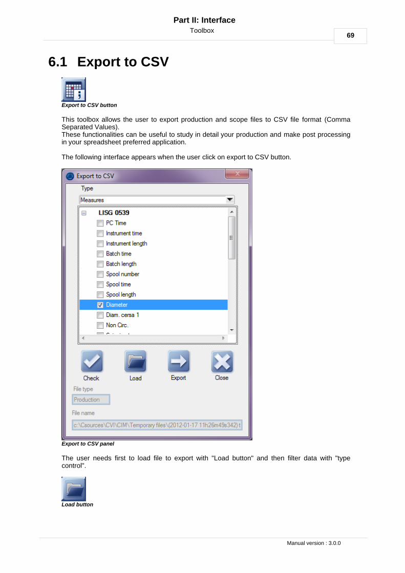
Export to CSV6.1
Export to CSV button
This toolbox allows the user to export production and scope files to CSV file format (CommaSeparated Values).These functionalities can be useful to study in detail your production and make post processingin your spreadsheet preferred application.
The following interface appears when the user click on export to CSV button.
Export to CSV panel
The user needs first to load file to export with "Load button" and then filter data with "typecontrol".
Load button

70
CIM. Cersa Instruments Manager. User's manual.
Part II: Interface
© 2012 CERSA-MCI
Manual version : 3.0.0
Toolbox
Type control
· For production files measures or events can be selected for export. They need to beexported in different files.
· For scopes files "type control" is hidden and the table shows available scopes in file.
To make export the user needs to select items with check button or by left clicking in item checkbox.To export data in CSV file you need to click in export button. Then file select pop up appears toask the name and location of the file to save.
Measure export
Export arrange measure values by columns. Measure 1, Measure 2, ...., Measure N
Measures export
Event export
Export arrange events by rows. For each event the following fields are specified:
· Event type: start or stop out of high/low tolerances.· Event type name: the name of event in interface.· Argument: for out of tolerances events, the argument corresponds to the extrema value.· PC time [hour:minutes:seconds]: time on which event occurs dated by PC relative to the
beginning of the batch.· Batch time [seconds]: the time when the event occurs from the beginning of the batch.· Batch position [meters]: the event position from the beginning of the batch.· Spool: the spool number in which the event was located.· Spool time [seconds]: the time when the event occurs from the beginning of the spool.· Spool position [meters]: the event position from the beginning of the spool.

71
Part II: Interface
Manual version : 3.0.0
Toolbox
Events export
Scope export
The exported file contains:
· Parameters related to the scope.· Results related to the scope.· Scope signals: (X axis signal 1, Y axis signal 1), (X axis signal 2, Y axis signal 2), ... , (X axis
signal N, Y axis signal N). For more details about scope structures please read scopemanager chapter.
Scope export
Because the scope files can contains multiples scope sequences, the export function willcreates multiple files with the following name structure.
Name of the file give by the user - Internal scope name - incremental value.csv

72
CIM. Cersa Instruments Manager. User's manual.
Part II: Interface
© 2012 CERSA-MCI
Manual version : 3.0.0
Connexions manager
Connexions manager7
Connexions manager button
Connexions manager interface gives the capability to add instruments in lines.
Connexions manager panel
Configuration fields
· Select instrument controls: display all the CERSA instruments offer.· Port number: CIM displays the list of all COM ports found by windows operating system.· Comm. period: The communication period between CIM and instrument in seconds. CERSA-
MCI recommends to set this period to 1 second to minimize the amount of recorded data andfree processor resources.
· Connexion prefix: Prefix used to display each measure and event names belonging to theconnexion.
· Connexion type: Physical type of connexion link. Validated only for RS232. · Baudrate: Baudrate configuration used by the instrument. By default set to 115200.· Network address: Address of connexion in network. By default set to 1.· Line number: If CIM instance manage only one line, the default value is 1. If CIM manage
several lines, the line number values must be different for each line. Please read linesmanager topic for more information about line names.
· Rel. position: Is the distance in meters between instrument and zero reference for lengthcounting system.
· Master instrument: Only one instrument in the line can have the master attribute. Thisattribute is used for display purposes only. For example: reset lines, spool time, spool lengthand spool number measures are displayed by default only for master instrument.
Please refer to the instrument manual for more details about the connexion type, baudrate and

73
Part II: Interface
Manual version : 3.0.0
Connexions manager
network adress settings.
Add connexion
Add connexion button
To add a new instrument to the current configuration, you first have to set all previousparameters and click on add button.
Delete connexion
Delete connexion button
To delete connexion, select the corresponding line in the table and click in delete button.
Any change in the user configuration requires a reset in the line. The following messageappears to prevent the user that all the data will be lost:
Reset line message
Start/Stop
Start stop button
This function will starts or stops the communication between CIM and the instrument. In thesame time CIM opens or closes the COM port. This function is very useful if another applicationneeds the same COM port to configure instrument.
Save Preset
Save preset button
Save the user configuration for connexions belonging to the line. The following data are storedfor each connexion:
· Display zone: the zone where measures and events are displayed. · Colors: colors used to display measures and events. · Offset and amplitude: offset and amplitude values used to display measures in graphs.· Position: position of measures and events in tables and graphs.
Load Preset

74
CIM. Cersa Instruments Manager. User's manual.
Part II: Interface
© 2012 CERSA-MCI
Manual version : 3.0.0
Connexions manager
Load preset button
This function load preset in empty line. To use it you need to select the empty line with "Linenumber" field.

75
Part II: Interface
Manual version : 3.0.0
Lines manager
Lines manager8
Lines manager button
All the general and production configuration of your line is available in this interface.
Lines manager panel
Remark:
· The parameters in this interface can not be modified during the production (production status:green).
Here below are listed the detail of options available in line manager interface:
· Line number: the line number is the line identifier. It doesn't represent the line number in yourfactory but an unique internal identifier, used to make the difference between lines controlledwith the same CIM instance.
· Line name: use this field to enter the names of your lines in your factory. For example if youhave 3 lines: Machine 1, Machine 2 and Machine 3.
· Default X mode: the default X mode used to display measures and events in productiongraphs.
· Default X reference: the default X reference used to display measures and events inproduction graphs.
· Default current time [minutes]: the default time used to display measures and events inproduction graphs when the current mode is selected.
· Default current length [meters]: the default length used to display measures and events in
76
CIM. Cersa Instruments Manager. User's manual.
Part II: Interface
© 2012 CERSA-MCI
Manual version : 3.0.0
Lines manager
production graphs when the current mode is selected. When the user makes changes of X axis settings in production interface, the user can restorethe default configuration listed above. Read more details about mode and reference settingsmanagement in production x axis chapter.· Production configuration: specifies the way in which product orders are launched. Read
product configuration chapter for more details. · Database report: indicates if database report is required. Read data logging chapter for more
details. · Data file record: indicates if file data logging is required. Read data logging chapter for more
details. · Start and stop production: these fields configure trigger used by CIM to detect production
start and stop. Read start and stop production chapter for more details.· PLC: this interface displays communication settings for programmable logical controller. Read
PLC topic for more details.· Product features: this interface defines features used for product specifications. Read
product features topic for more details.· Product specification: the user can defines with this interface specification for products.
Read product specification topic for more details.· Feature link: makes relationships between features and instruments belonging to the line.
Read feature link topic for more details.· Product order: this interface gives the possibility to launch production in any CIM registered
system. Read product order topic for more details.

77
Part II: Interface
Manual version : 3.0.0
Lines manager
Production configuration8.1
The production can be managed in two modes:
· Programmed mode, the product order is read from CIM_PRODUCT database. o You can write the order with CIM product order interfaceo Or you can develop an external system to program the orders in your factory.
· In manual mode the product order is requested by the software at the end of previousproduction. The operator have to indicate the product type and the batch name manually.
Remark:
· When the production configuration is enabled, product features, product specification andfeature link interfaces are not available. You need to disable the production configuration inorder to specify your products.
Production configuration disabled icon.
Manual production configuration enabled icon.
Programmed production configuration enabled icon.
Chose database path icon

78
CIM. Cersa Instruments Manager. User's manual.
Part II: Interface
© 2012 CERSA-MCI
Manual version : 3.0.0
Lines manager
Data logging8.2
Database report
All the results of your production can be stored in distant or local database. To get databasereport you have to:
· Enable product configuration.· Define specifications of your products in product specification interface. · You need also to set links (see feature links for more details).
Database report disabled / enabled icons.
Chose database path icon
Remark:
· In order to enable production configuration and the database report, you need to choosesources database. You can use database models located at c:\ProgramFiles\Cersa\CIM\Database folder.
Data file record
Enable this option to record automatically your batch data in a CIM production file. The createdfile name has the following format:
RecordPath/Time LineName BatchName.ext
· Time: in YEAR-MONTH-DAY HOUR:MINUTE:SECONDS format.· LineName: the name of the line.· BatchName: specified by operator in manual product configuration or by external system in
automatic external configuration.· ext: extension for production files. cimzip for compressed files and cimprd for uncompressed
files. See more details about extensions in Load file topic.
For example: C:\Program Files\Cersa\CIM\Records\2010-05-30 20:53:59 Machine_1 PREF1.cimprd
CIM data file record disabled / enabled icons.
Chose path icon

79
Part II: Interface
Manual version : 3.0.0
Lines manager
Start and stop production8.3
The production can be started and stoped automatically with different criteria:
Start with speed
This option defines if the production will refer to the line speed conditions to start (start speedtrigger and start during time).
Start with speed disabled / enabled icons.
· Start speed trigger: determines the speed in meters per seconds to be exceeded to start theproduction.
· Start during time: determines the time in seconds needed to start production when the startspeed trigger condition has been exceeded.
Stop with speed
This option defines if the production will refer to the line speed conditions to stop (stop speedtrigger and stop during time).
Stop with speed disabled / enabled icons.
· Stop speed trigger: determines the speed in meters per seconds below which the productionis stopped.
· Stop during time: determines the time in seconds needed to stop production when the stoptrigger condition has been reached.
Remark:
· The start speed trigger must have a superior value than the stop trigger.
Start on reset spool
This option defines if the production will refer to the reset signal to start.
Start with reset disabled / enabled icons
Start on date (Not available yet.)
Start with date disabled / enabled icons.
Stop on date (Not available yet.)

80
CIM. Cersa Instruments Manager. User's manual.
Part II: Interface
© 2012 CERSA-MCI
Manual version : 3.0.0
Lines manager
Stop with date disabled / enabled icons.

81
Part II: Interface
Manual version : 3.0.0
Lines manager
Product features8.4
Product features panel
To better understand the product configuration we need to define the following concepts:
Feature classesDefines the physical magnitude to control with instruments (for example the diameter). Thisconcept takes in account the measure, the events and the tolerances. Thus feature classestable lists all the magnitudes to control.
Feature typesDefines the types of tolerances to configure for each magnitude (for example: nominal diameter,high diameter and low diameter). The feature types table lists all the tolerances than can beconfigured.
All these features are stored in CIM_PRODUCT database (global to the factory or specific forseveral lines) and are needed to build report in CIM_REPORT database. These features are thebases to build product specifications and are completely customizable in order to cover the needof your factory.
A default list is already present in CIM interface and, normally, covers customer needs. Ifadditional features are needed you can use Add, Delete and Update buttons to build newconfiguration.

82
CIM. Cersa Instruments Manager. User's manual.
Part II: Interface
© 2012 CERSA-MCI
Manual version : 3.0.0
Lines manager
Product specification8.5
Product specification panel
This interface defines the tolerances for your products.
· Product type: select current product to modify.· Add product type: will create new product and corresponding default features in
CIM_PRODUCT database.· Delete product type: will delete the selected product type.· Update product type: give you the possibility to change the name of your product.
The product specification table display all the tolerances for the selected product.
· Add new feature from your feature list: select in feature types ring control the feature andclick on add feature button to enter the correspondent value.
· Delete feature type: will delete feature from current product.· Update feature type: gives the capability to modify the current value of the feature.

83
Part II: Interface
Manual version : 3.0.0
Lines manager
Feature link8.6
Feature link panel
To finish the configuration of products in your factory you need to make links between thefeatures and the instrument that will control these features. You have to repeat this procedurefor each production line.
Feature tables display all the features, in the first column, and the corresponding link with theinstrument, in the second column. You need to link feature types with tolerances and featureclasses with events.
For example:· Cladding diameter is controlled with LIS-G for the current line. o You need to select LIS-G instrument in select instrument control.o Select Nominal diameter tolerance in Tolerances table.o Select Cladding diameter nominal in Feature types table.o Push link button.o The link appears in second column of feature types table.
· Make the same actions for all the features. Change the instrument when necessary.· Make also the links for feature classes.
Remark:
· Your configuration is completed if all features types and features classes are linked.

84
CIM. Cersa Instruments Manager. User's manual.
Part II: Interface
© 2012 CERSA-MCI
Manual version : 3.0.0
Lines manager
Product order8.7
Product order panel
This interface gives the capability to send an order to any line sharing your productconfiguration. To share the same product configuration you need to declare the sameCIM_PRODUCT database path. Read lines manager topic for more information about how toselect database path.
You need to:
· Select the line.· Select the product to produce.· Click on Add button, Then the batch name will be requested.
A new line appears in order table with red status. When the status changes to green color theline has taken in account the order. When the production is finished the status of the orderbecomes red.
You can delete orders only when the status of the order is red by clicking on delete button.

85
Part II: Interface
Manual version : 3.0.0
Preferences
Preferences9
Preferences button
Preferences interface contains options related to the software.
· Change password: See change password topic for more details.· File compression: This option will compress CIM files automatically when the user make
save selection, save scopes, save sequence or in automatic cim data file record. Compressedfiles have .cimzip extension.
· Cim Id: Unique identifier for CIM instance in your factory. This parameter is absolutelynecessary in case of external database architecture. Please refer to line manager topic formore details about line production configuration.

86
CIM. Cersa Instruments Manager. User's manual.
Part II: Interface
© 2012 CERSA-MCI
Manual version : 3.0.0
Preferences
Change password9.1
Change password panel
This interface allows you to change password for customer levels. To make this please followthis procedure:
· Select the level to change.· Enter the new password.· Confirm the new password.· Apply changes.
To modify supervisor and user password you need to know supervisor password in order todisplay preferences and change password interfaces.

87
Part II: Interface
Manual version : 3.0.0
Touchpad panel
Touchpad panel10
Touchpad interface
Touchpad interface appears when the user needs to enter text or numeric value by touching thecontrol.Restore button gives the capability to restore the source value.
Here below is presented the available configuration of touchpad:
Numeric pad
Uppercase pad
Lowercase pad
Symbols pad

88
CIM. Cersa Instruments Manager. User's manual.
Part III: Client databases
© 2012 CERSA-MCI
Manual version : 3.0.0
Part III: Client databasesTwo client’s databases CIM_REPORT and CIM_PRODUCT will be hosted in local or distantmachine (ethernet access). See required PC specifications for more details about networkconfiguration.The database type is SQLITE3. (Used by Symbian, Mozilla, Adobe, Bloomberg…).
SQLITE3 general information:
· The ODBC driver for windows NT/2000/XP will be provided by CERSA. It is conform toSQL-92 standard (ISO 9075).
· For more information about SQLITE3 please visit:http://www.sqlite.orghttp://www.ch-werner.de/sqliteodbc/

89
Part III: Client databases
Manual version : 3.0.0
Database relationships
Database relationships1

90
CIM. Cersa Instruments Manager. User's manual.
Part III: Client databases
© 2012 CERSA-MCI
Manual version : 3.0.0
CIM product database
CIM product database2
This database contains the features (measurements parameters) for different products, and theproduction orders. See lines manager topic for more details about features.
CIM_PRODUCT database contains 8 tables described here below.

91
Part III: Client databases
Manual version : 3.0.0
CIM product database
TB_CIM_LINE_STATEMENT2.1
This table contains statements for every line using CIM_PRODUCT database in factory.
Field Description Datatype
Units R/W
INT_StatementId(Primary key)
Identifier for statement. INTEGER
Nounits
Read/Write
INT_CimId Identifier for CIM target application thatcontrols the line in which you want toproduce.
INTEGER
Nounits
Read/Write
INT_LineNumber Line identifier given by CIM when line iscreated.
INTEGER
Nounits
Read/Write
CHR_LineName Client line name. CHAR(96)
Nounits
Read/Write
Remark:
· Every CIM application must have a unique identifier (INT_CimId) which can be set by userinterface (See preferences topic for more details). Line number and line name can be set alsoby user interface (See lines manager topic for more details).
· This table is completely managed by CIM.

92
CIM. Cersa Instruments Manager. User's manual.
Part III: Client databases
© 2012 CERSA-MCI
Manual version : 3.0.0
CIM product database
TB_FEATURE_CLASS2.2
This table lists all features classes that can be controlled and managed by CERSA instrumentsin production process. These features classes are associated with instrument events andmeasures. See Product features topic for more detail about features.
Field Description Datatype
Units R/W
INT_FeatureClass(Primary key)
Feature class identifier. INTEGER
Nounits
Read/Write
CHR_FeatureClassName
Client feature class name. CHAR(96)
Nounits
Read/Write

93
Part III: Client databases
Manual version : 3.0.0
CIM product database
TB_FEATURE_CLASS_EVENT_LINK2.3
This table contains links between feature classes, instrument events and measures.
Field Description Datatype
Units R/W
INT_CodeConnexionsNumber
Identifier code of instrument event andmeasure in CIM interface
INTEGER
Nounits
Read
INT_FeatureClass Feature class identifier. INTEGER
Nounits
Read
INT_LineNumber Line identifier given by CIM when line iscreated.
INTEGER
Nounits
Read
CHR_LineName Client line name. CHAR(96)
Nounits
Read
Remark:
· This table is completely managed by CIM user interface and is accessible only for reading.

94
CIM. Cersa Instruments Manager. User's manual.
Part III: Client databases
© 2012 CERSA-MCI
Manual version : 3.0.0
CIM product database
TB_FEATURE_TYPE2.4
This table lists all features types necessaries to whole characterize products in your factory.These features types will configure instrument tolerances. See Product features topic for moredetail about features.
Field Description Datatype
Units R/W
INT_FeatureType(Primary key)
Feature type identifier. INTEGER
Nounits
Read/Write
CHR_FeatureTypeName
Client feature type name. CHAR(96)
Nounits
Read/Write

95
Part III: Client databases
Manual version : 3.0.0
CIM product database
TB_FEATURE_TYPE_TOLERANCE_LINK2.5
This table contains links between feature types and instrument tolerances.
Field Description Datatype
Units R/W
INT_CodeConnexionsNumber
Identifier code of instrument toleranceparameter.
INTEGER
Nounits
Read
INT_FeatureType Feature class identifier. INTEGER
Nounits
Read
INT_LineNumber Line identifier given by CIM when line iscreated.
INTEGER
Nounits
Read
CHR_LineName Client line name. CHAR(96)
Nounits
Read
Remark:· This table is managed by CIM user interface and is read-only accessible.

96
CIM. Cersa Instruments Manager. User's manual.
Part III: Client databases
© 2012 CERSA-MCI
Manual version : 3.0.0
CIM product database
TB_PRODUCT_TYPE2.6
In this table, the customer lists the product types used in the factory.
Field Description Datatype
Units R/W
INT_ProductType(Primary key)
Product identifier. INTEGER
Nounits
Read/Write
CHR_ProductName Client product name. CHAR(96)
Nounits
Read/Write
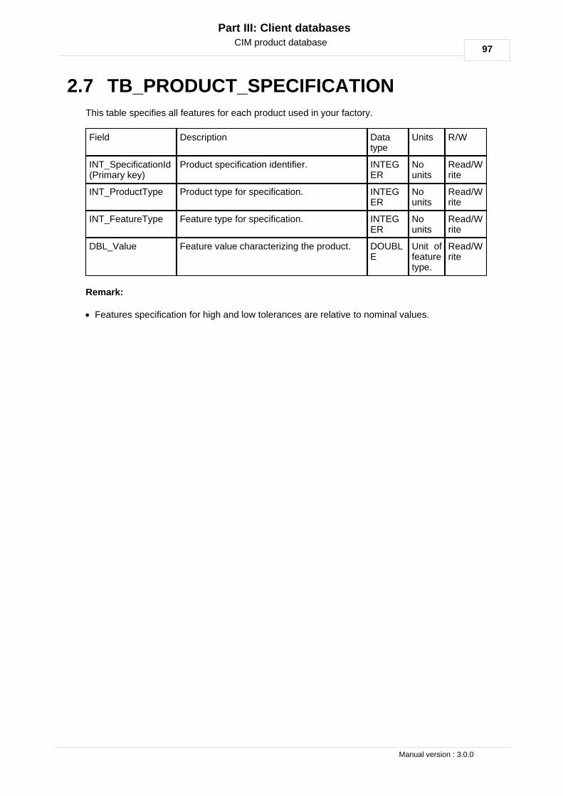
97
Part III: Client databases
Manual version : 3.0.0
CIM product database
TB_PRODUCT_SPECIFICATION2.7
This table specifies all features for each product used in your factory.
Field Description Datatype
Units R/W
INT_SpecificationId(Primary key)
Product specification identifier. INTEGER
Nounits
Read/Write
INT_ProductType Product type for specification. INTEGER
Nounits
Read/Write
INT_FeatureType Feature type for specification. INTEGER
Nounits
Read/Write
DBL_Value Feature value characterizing the product. DOUBLE
Unit offeaturetype.
Read/Write
Remark:
· Features specification for high and low tolerances are relative to nominal values.

98
CIM. Cersa Instruments Manager. User's manual.
Part III: Client databases
© 2012 CERSA-MCI
Manual version : 3.0.0
CIM product database
TB_PRODUCT_ORDER2.8
This table will register all production orders make by the external database system. When theclient wants to produce specific product, client database application or CIM user interface mustwrite in this table the product to draw and set INT_StartOrder flag to 0. As soon as CIM will readit, it will switch to 1. When production of the current order is finished, CIM store the last spoolnumber and change flag "INT_StartOrder" to 2.
Field Description Data type Units R/W
INT_OrderId(Primary key)
Product order identifier. INTEGER
Nounits
Read
CHR_DateTimeOrder
Date and time at which the order has beenrequested.
CHAR(260)
YYYY-MM-DDHH:MM:SS.SSS
Write
INT_CimId Identifier for CIM target application thatcontrols the line in which you want toproduce.
INTEGER
Nounits
Write
INT_LineNumber Line number in which you want to produce. INTEGER
Nounits
Write
CHR_BatchName Name of batch to produce. CHAR(96)
Nounits
Write
INT_ProductType Type of product to produce. INTEGER
Nounits
Write
INT_StartOrder This flag permits CIM to know which orderhas been take in account.
INTEGER
Nounits
Write
INT_LastSpool The number of last spool produced forcurrent order.
INTEGER
Nounits
Read

99
Part III: Client databases
Manual version : 3.0.0
CIM report database
CIM report database3
When starting the production or when changing a preform (batch), a new CIM data file iscreated automatically. This data file contains all measurements and events from theinstruments.
Because the CIM data file is not readable by other software, we store the summarised data foreach spool in this client’s database.
CIM_REPORT database contains 4 tables.
Remark:
· The maintenance of these 4 tables has to be done by the client. In order to limit the size ofthose tables, we recommend you to erase the records periodically.

100
CIM. Cersa Instruments Manager. User's manual.
Part III: Client databases
© 2012 CERSA-MCI
Manual version : 3.0.0
CIM report database
TB_SPOOL3.1
This table contains necessary information to identify spools in production management.
Field Description Data type Units R/W
INT_SpoolId (Primarykey)
CIM_REPORT database spoolidentifier.
INTEGER
No units Read
INT_SpoolNumber Spool number for specific batch. INTEGER
No units Read
DBL_SpoolLength Spool length. DOUBLE meters Read
CHR_SpoolDateTimeStart
Start date and time of the spool. CHAR(32)
YYYY-MM-DDHH:MM:SS.SSS
Read
CHR_SpoolDateTimeEnd
End date and time of the spool. CHAR(32)
YYYY-MM-DDHH:MM:SS.SSS
Read
INT_CimId Identifier for CIM target applicationthat controls the line in which youwant to produce.
INTEGER
No units Read
INT_LineNumber Line number in which you want toproduce.
INTEGER
No units Read
INT_ProductType Product type for spool. Producttypes are defined inCIM_PRODUCT database inTB_CLIENT_PRODUCT_TYPEtable.
INTEGER
No units Read
CHR_BatchName In optical fibre configuration thisfield corresponds to preform name.
CHAR(96)
No units Read
CHR_CimDataFileRecordPath
CIM data file record path. CHAR(260)
No units Read

101
Part III: Client databases
Manual version : 3.0.0
CIM report database
TB_SPOOL_FEATURE_CLASS_EVENTS3.2
Contains summary information about events detected for each spool. Instrument events areassociated with feature classes (defined in CIM_PRODUCT database in TB_FEATURE_CLASStable).
Field Description Data type Units R/W
INT_SpoolEventId(Primary key)
Event type identifier. INTEGER
No units Read
INT_SpoolId CIM_REPORT database spool identifier. INTEGER
No units Read
INT_FeatureClass Feature class. It represents event types(diameter tolerances, defects, …)
INTEGER
No units Read
INT_HighLowToleranceSign
If positive specifies high out of tolerance.If negative specifies low out of tolerance.
INTEGER
No units Read
INT_NumberOfEvents
Number of occurrences for event inspool.
INTEGER
No units Read
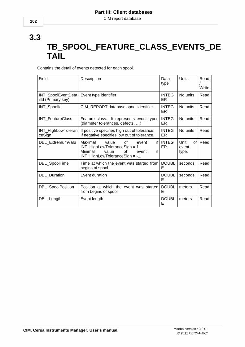
102
CIM. Cersa Instruments Manager. User's manual.
Part III: Client databases
© 2012 CERSA-MCI
Manual version : 3.0.0
CIM report database
TB_SPOOL_FEATURE_CLASS_EVENTS_DETAIL
3.3
Contains the detail of events detected for each spool.
Field Description Datatype
Units Read/Write
INT_SpoolEventDetailId (Primary key)
Event type identifier. INTEGER
No units Read
INT_SpoolId CIM_REPORT database spool identifier. INTEGER
No units Read
INT_FeatureClass Feature class. It represents event types(diameter tolerances, defects, …)
INTEGER
No units Read
INT_HighLowToleranceSign
If positive specifies high out of tolerance.If negative specifies low out of tolerance.
INTEGER
No units Read
DBL_ExtremumValue
Maximal value of event ifINT_HighLowToleranceSign = 1. Minimal value of event ifINT_HighLowToleranceSign = -1.
INTEGER
Unit ofeventtype.
Read
DBL_SpoolTime Time at which the event was started frombegins of spool.
DOUBLE
seconds Read
DBL_Duration Event duration DOUBLE
seconds Read
DBL_SpoolPosition Position at which the event was startedfrom begins of spool.
DOUBLE
meters Read
DBL_Length Event length DOUBLE
meters Read

103
Part III: Client databases
Manual version : 3.0.0
CIM report database
TB_SPOOL_FEATURE_CLASS_STATISTICS3.4
This table gives necessary statistic information to qualify and certify the spool production.
Field Description Data type Units Read/Write
INT_SpoolStatisticId (Primary key)
Statistic identifier for this table. INTEGER
No units Read
INT_SpoolId CIM_REPORT database spool identifier. INTEGER
No units Read
INT_FeatureClass Feature class. It represents measuretypes (diameter , tension …)
INTEGER
No units Read
DBL_ErrorPercentage
Percentage of invalid measures (due todefects, fibre out of position…)*
DOUBLE % Read
DBL_ProcessCapabilityCp
Process capability Cp index. ** DOUBLE No units Read
DBL_ProcessCapabilityCpk
Process capability Cpk index. ** DOUBLE No units Read
DBL_Average Measure of “middle” or “expected value”of process. Obtained by arithmetic mean,geometric mean…***
DOUBLE Unit ofmeasuretype.
Read
DBL_StandardDeviation
Measure of process spread. Obtained bycomputing square root of variance. ***
DOUBLE Unit ofmeasuretype.
Read
DBL_MinimalValue Minimal value of measure in process. DOUBLE Unit ofmeasuretype.
Read
DBL_MaximalValue Maximal value of measure in process. DOUBLE Unit ofmeasuretype.
Read
Remarks:
* Statistics includes only valid measures.
** Process capability:
USL = Upper set limit.LSL = Lower set limit.s = Standard deviation.m = Nominal value of specifications.µ = Process average.
*** Average:

104
CIM. Cersa Instruments Manager. User's manual.
Part III: Client databases
© 2012 CERSA-MCI
Manual version : 3.0.0
CIM report database
xi = Data set.n = number of measures.
**** Standard deviation:


