
P/N 10096880 REV A © Hydro Systems Company, Inc. 2014 HydroSystemsCo.com Toll Free: 1.800.543.7184 1
Reference Manual Antares Series
Preface
This manual has been written and illustrated to present the basic installation, operation, and servicing instructions of the Antares Warewash Dispensing System. Guidelines will be suggested in reference to the preferred method of installation, however, the variety of equipment and the surrounding environment will dictate the actual installation of the Antares.
Antares Warewash Dispensing System
Online and downloadable Product Manuals and Quick Start Guides are available at www.HydroSystemsCo.com Please check online for the latest version of this Reference Manual.
!WARNING:The Antares dispensing system is intended to be installed by experienced installers, inaccordance with all applicable electrical and plumbing codes.
All dish machine and dispenser power must be disconnected during installation and/orany time the dispenser cabinet is opened.
NOTE: Always use proper lockout tagout procedures when servicing the dispenser.
Antares DM-6000

P/N 10096880 REV A © Hydro Systems Company, Inc. 2014 HydroSystemsCo.com Toll Free: 1.800.543.7184 2
Table of Contents
1 Product Benefits ....................................................................................................................................4 2 System Specifications ..........................................................................................................................4 3 Mechanical Installation Overview ..........................................................................................................................................5 Wall Mounting ..................................................................................................................................6 Probe Mounting ...............................................................................................................................6 Rinse Injection Fitting .......................................................................................................................7 Detergent Bulkhead Fitting ..............................................................................................................7
Probe Kit Wiring Guides ...................................................................................................................8 Rinse and Detergent Supply and Discharge Tubes .........................................................................9
Solenoid Water Feed ........................................................................................................................9 4 Electrical Installation Overview ........................................................................................................................................10 Probe Wiring ..................................................................................................................................10 Electrical Connections ...................................................................................................................11 Main Power Wiring .........................................................................................................................11 Detergent Signal Wiring .................................................................................................................11 Rinse Signal Wiring ........................................................................................................................12 5 Operating Modes .................................................................................................................................12 Overview ........................................................................................................................................12 6 Operating Modes: Probe Operation Mode Detergent Control ...........................................................................................................................12 Rinse Control .................................................................................................................................12 Conveyor Machines .......................................................................................................................13 Door Machines ...............................................................................................................................13 Pulse Feed .....................................................................................................................................13 7 Operating Modes: Probeless Operation Mode Initial Charge ..................................................................................................................................14 Detergent Dose ..............................................................................................................................14 Low Detergent Alarm Threshold ....................................................................................................15 Rinse Control .................................................................................................................................15 Rack Counts ..................................................................................................................................15 Rinse Delay Time (Door Machines Only) ........................................................................................15 Rinse Saver (Door Machines Only) ................................................................................................15 Rinse Feed Option (Door Machines Only) ......................................................................................15 Tank Change Interval .....................................................................................................................15 8 Programming Menus, Screens, and Setup Start-up Splash Screen ..................................................................................................................16 Language Selection .......................................................................................................................16 Date and Time Set .........................................................................................................................16 Home Screen .................................................................................................................................17 Keypad, Menus, and Symbols .......................................................................................................17 Navigation to User/Program Menus ..............................................................................................18 Power Saver ...................................................................................................................................18 User Menus ....................................................................................................................................18 User Prime Pumps .........................................................................................................................18 De-Lime Cycle ...............................................................................................................................19 Max Detergent Time .......................................................................................................................19 Manual Initial Charge .....................................................................................................................19 Manager Reports ...........................................................................................................................20 Download Productivity Report .......................................................................................................20 Installer Password ..........................................................................................................................20 Configuration Settings ...................................................................................................................21 Detergent Control ...........................................................................................................................21 Machine Type .................................................................................................................................21 Detergent Type ...............................................................................................................................21 Pulse Feed Settings .......................................................................................................................21 Alarm Options ................................................................................................................................22 Set Units of Measure .....................................................................................................................22 Auto Switch Mode .........................................................................................................................22 Conveyor Rack Time ......................................................................................................................22 Initial Charge ..................................................................................................................................22 Display Live Conductivity ...............................................................................................................23 Display Live Rinse Temperature .....................................................................................................23 Third Product Run ..........................................................................................................................23 User Prime .....................................................................................................................................23 Program Settings (Probe Mode Only) ............................................................................................24 Detergent Set Point ........................................................................................................................24 Manually Add Product ...................................................................................................................24 Enter Set Point ...............................................................................................................................24 Use Tank Reading ..........................................................................................................................24 Rinse Pump Speed (Probe Mode) .................................................................................................25 Third Product Pump Speed (Probe Mode) .....................................................................................25 Rinse Feed Option (Probe Mode)...................................................................................................25 Rinse Delay Time (Door Machines Only) ........................................................................................26 Program Settings (Probeless Mode Only) ......................................................................................26

P/N 10096880 REV A © Hydro Systems Company, Inc. 2014 HydroSystemsCo.com Toll Free: 1.800.543.7184 3
Table of Contents
8 Programming Menus, Screens, and Setup (cont’d.) Detergent Initial Charge .................................................................................................................26 Detergent Dose ..............................................................................................................................27 Detergent Dose Interval .................................................................................................................27 Rinse Pump Speed (Probeless Mode) ...........................................................................................27 Third Product Pump Speed (Probeless Mode) ..............................................................................28 Rinse Feed Option (Probeless Mode) ............................................................................................28 Rinse Delay Time (Door Machines Only) ........................................................................................28 Low Detergent Alarm Threshold ....................................................................................................28 Alarm Settings Menu ......................................................................................................................29 Low Detergent Alarm Delay/Detergent Overfeed ..........................................................................29 Stop Alarm .....................................................................................................................................29 Machine Clean Alarm Setting (Probed and Probeless) ..................................................................29 Conductivity Probe Range Setting (Probe Mode Only) ..................................................................30 Change Tank Alarm ........................................................................................................................30 Change Squeeze Tube Time ..........................................................................................................30 Low Rinse Temp Setting ................................................................................................................30 Installer Service ..............................................................................................................................30 Service Pumps ...............................................................................................................................31 View Pump Configuration ..............................................................................................................31 Name Pumps .................................................................................................................................31 Prime Pumps..................................................................................................................................31 Pump Calibration ...........................................................................................................................32 View Calibration .............................................................................................................................32 Calibrate Pumps (Non-Solenoid) ...................................................................................................32 Calibrate Pumps (Solenoid) ...........................................................................................................32 Enter Product Cost ........................................................................................................................33 Tube Replacement Date .................................................................................................................33 Set Pump Type ...............................................................................................................................34 Set Pump Product..........................................................................................................................34 Set Pump Install .............................................................................................................................34 View Amount Pumped ...................................................................................................................34 Clear Data Log ...............................................................................................................................35 Initial System Setup .......................................................................................................................35 Edit Installer Password ..................................................................................................................35 Edit Manager Password .................................................................................................................35 Edit Account Name/Edit Machine Name/Edit ................................................................................36 Company Name .............................................................................................................................36 Set LCD Contrast ...........................................................................................................................36 Set Date & Time .............................................................................................................................36 Clear Settings.................................................................................................................................36 View Software ID ............................................................................................................................37 View Serial Number ........................................................................................................................37 Signal Display Enable ....................................................................................................................37 External Solenoid Enable ...............................................................................................................37 Electric Cost/KWH .........................................................................................................................37 Water Unit Cost ..............................................................................................................................37 Full KW Power Usage ....................................................................................................................37 Idle KW Power Usage ....................................................................................................................38 Water Volume/Wash .......................................................................................................................38 Data Transfer ..................................................................................................................................38 Write Reports .................................................................................................................................39 Read Setup ....................................................................................................................................39 Write Setup ....................................................................................................................................40 Update Firmware ...........................................................................................................................40 9 Alarm Messages Detergent Overfeed Stop Alarm .....................................................................................................41 Machine Clean Alarm .....................................................................................................................41 Conductivity Probe Faulty Alarm ...................................................................................................41 Squeeze Tube Change Alarm.........................................................................................................41 Change Tank Alarm (Probeless Mode) ...........................................................................................41 Low Rinse Temperature Alarm .......................................................................................................41 Pump Jam Alarm ...........................................................................................................................42 Probe Not Calibrated Alarm ...........................................................................................................42 10 Reports Productivity Report ........................................................................................................................43 Settings Report ..............................................................................................................................44 Activity Report................................................................................................................................46 Diagnostic Report ..........................................................................................................................48 11 Maintenance and Service Spare Parts Listing ........................................................................................................................49 12 Specifications and Warrant Specifications ................................................................................................................................51 13 Index ....................................................................................................................................................52

P/N 10096880 REV A © Hydro Systems Company, Inc. 2014 HydroSystemsCo.com Toll Free: 1.800.543.7184 4
Product Benefits
Advanced DesignThe Antares uses surface mount electronic components to provide powerful features in a small package. A multi-line LCD screen allows intuitive programming of all options.
ReliabilityThe gasket-enclosed Antares Warewash Dispenser is highly water resistant and the electronics are protected within the enclosure. The readout gives confirmation of detergent and rinse signals.
VersatilityThe Antares can be configured as a conductivity probe controlled unit or as a probeless, time-baseddispenser. It can accept a 100-249VAC nominal (+/- 10% fluctuation) main power input at 50 or 60 Hz. Rinse and Detergent control signals are universal “machine interface” types that are capable of accepting any voltage from 24 to 240 VAC nominal (+/- 10% fluctuation) or 24 VDC (+/- 10% fluctuation). Antares can control either capsule or liquid detergents.
Cost SavingsA special Rinse Saver Feature prevents rinse additive waste during fills of the washer. Digital electronicsensure accurate detergent control and minimize overuse. The Antares contains energy management features which can be used to track water and power usage and cost per rack over time. Reports indicate percentage of racks washed successfully and racks where alarms occurred.
IntelligenceThe Antares includes a rack counter as a “standard” feature. A unique “De-Lime” mode allows forsafe washer cleaning without detergent waste.
Choice of OptionsA full range of programmable options are included, such as Rinse Delay, Variable Alarm Volume, and Manual Prime for both rinse and detergent. Hardware options include detergent tank and rinse probe temperature.
Easy Service/RepairThe Antares features convenient front access for all services. No internal access to the cabinet is required for installation and routine maintenance. Spare parts are available in modular form for fast, convenient repairs.
System SpecificationsDetergent input signal 24 to 250VAC 50/60 HZ 20mARinse input signal 24 to 250VAC 50/60 HZ 20mATank fill input signal 24 to 250VAC 50/60 HZ 20mA
Motor/solenoid drive outputs for detergent and rinseExternal solenoid output signal for rinse dissolver 24v DC Out
Conductivity probe for tank IncludedOptional temperature probe for rinse and wash tank Separate kit(s) required
Audible alarm within controller (single volume level) and external output for alarm (On/Off, no levels)USB type A, used for USB drive storage and Flash programming LCD display, 8 line by 20 character with adjustable contrast.
Multiple system configurations are available. Contact Hydro Systems customer service for more information.

P/N 10096880 REV A © Hydro Systems Company, Inc. 2014 HydroSystemsCo.com Toll Free: 1.800.543.7184 5
Mechanical Installation
Overview
This chapter describes the hardware installation of the Antares. In this chapter, you will:
• Wall-mount the Antares• Mount and install the probe (if applicable)• Mount and install the rinse injection fitting• Mount and install the detergent bulkhead fitting• Probe kit wiring guides• Install rinse and detergent supply and discharge tubes• Install solenoid (if applicable)

P/N 10096880 REV A © Hydro Systems Company, Inc. 2014 HydroSystemsCo.com Toll Free: 1.800.543.7184 6
Mechanical Installation
Wall Mounting
1. Choose an installation location that is: • Close to the product containers. • At a reasonable height for easy maintenance access and does
not interfere with opening of doors. • Away from any direct sources of steam, water spray, and high
temperatures. • Close enough to the dish machine electrical control panel to
allow dispenser wiring without use of an external junction box (not provided) wherever possible. Wire harness is 11.5 feet.
2. Using mounting bracket as a template, mark holes to drill into mounting surface. For sheet metal mounting with screws and nuts, drill 1/4” (6 mm) holes. For wall anchors, drill holes as appropriate for anchors used.
3. Attach mounting bracket to mounting surface with hardware provided.
4. Hang unit on bracket.
Probe Mounting (Probe Operation and Out of Product Alarm in Probeless Mode only)
The probe senses the detergent concentration. Correct probe placement is critical for accurate detergent concentration control. Always use the new probe provided with the dispenser.
1. Choose a mounting location that will allow the probe to be completely immersed in the wash tank solution, in an area that has a good flow of solution.
2. Check for a probe hole. Many dish machines will have knockouts provided for probe installation and/or will have existing probes. Previously punched probe holes may be suitable, but always confirm that the probe will be immersed in the wash tank solution before installing
3. If no suitable probe hole is present, drill a 3/8” hole in the center of the probe location. Use a Greenlee (or similar) 7/8” hole punch to cut the final hole.
4. Remove the probe retaining nut.
5. From inside the dish machine tank wall, insert probe (with rubber gasket) into hole.
6. From outside the dish machine tank wall, install second rubber gasket, plastic washer and probe retaining nut. Tighten finger-tight only. Using a wrench, snug retaining nut without over tightening.
!WARNING:The Antares dispensing system is intended to be installed by experienced installers inaccordance with all applicable electrical and plumbing codes.
All dish machine and dispenser power must be disconnected during installation and/orany time the dispenser cabinet is opened.
Mounting Bracket
Back of UnitHang unit from this lip on to Mounting Bracket
Figure 3-3 Mounting Bracket
Figure 3-4 Probe Mounting
!WARNING:Do not over-tighten the retaining nut!
Retaining Nut
Plastic WasherDish MachineTank Wall
LockWasher
NutRing
Terminal
Nut
Rubber Gasket
Rubber Gasket

P/N 10096880 REV A © Hydro Systems Company, Inc. 2014 HydroSystemsCo.com Toll Free: 1.800.543.7184 7
Compression Fitting(tube from pump)
Threads intorinse plumbing
Mechanical Installation
Rinse Injection Fitting
1. Choose a location to install the rinse injection fitting at least 6” below the dish machine rinse plumbing vacuum breaker to conform to plumbing codes. The injection fitting threads into 1/8” NPT female threads. If the dish machine rinse plumbing is thin-wall pipe, use a saddle clamp with a 1/8” NPT threaded hole. If an optional pressure switch will be used, thread the injection fitting into one side of the pressure switch water source fitting pipe tee.
2. Check for a tapped hole to accommodate the fitting. A suitable hole must be at least 6” downstream from the solenoid valve and vacuum breaker. On continuous rack, flight, or conveyor machines, be sure this location is downstream from any rinse by-pass water pipe.
3. If no suitable hole exists, drill an 11/32” hole in the rinse plumbing injection location.
4. Tap the hole with a 1/8” NPT tap. 5. Install the injection fitting. Use thread sealant to ensure a leak-free
assembly.
Detergent Bulkhead Fitting (Liquid Detergent Only)
Correct placement of the detergent bulkhead fitting is critical for accurate detergent concentration control (in probe mode only).
1. Choose a mounting location that ensures the detergent bulkhead fitting is:
• Above the water line in the tank. • Close to the probe location (when possible). • Discharging detergent directly into the wash tank and not on top of
any shelf areas or other obstacles that could prevent detergent from falling directly into the wash tank.
2. Previously punched holes may be suitable, but always confirm that the fitting is correctly placed.
3. If no suitable hole is available, drill a 3/8” hole in the center of the detergent inlet location. Use a Greenlee (or similar) 7/8” hole punch to cut the final hole.
4. Remove the detergent bulkhead fitting retaining nut. 5. From outside the machine, insert the detergent bulkhead fitting (with
rubber gasket) into hole.6. From inside the machine, install the second rubber gasket, plastic
washer and plastic retaining nut. Tighten finger-tight, then snug using wrench.
Figure 3-4 Rinse Injection Fitting
!WARNING:Follow the instructions provided with your solid, powder, or slurry feed system for solenoid equipped units instead of using the following section.
Figure 3-5 Detergent Bulkhead Fitting
!WARNING:Do not over-tighten the retaining nut! The installation instructions for the detergent bulkhead fitting are for liquid detergent feed systems only. Follow the instructions provided with your solid, powder, or slurry feed system for solenoid equipped units.

P/N 10096880 REV A © Hydro Systems Company, Inc. 2014 HydroSystemsCo.com Toll Free: 1.800.543.7184 8
Mechanical Installation
Rinse Probe Kit Wiring Guide
Disconnect all power to the unit before opening the front cover. Connect the other end of the cable to the 10096829 rinse probe assembly using the crimp-on spade connectors. Attach the two smaller connectors to the rinse probe wires, and the two larger connectors to the 2-conductor cable. (Polarity is not important).
T/C Probe Kit Wiring Guide
Connect the end of the cable to the 10096824 rinse probe assembly using the crimp-on spade connectors and ring terminals included in the kit. Attach the two smaller spade connectors to the white thermistor wires, and the two larger connectors to the green & white wires of the 4-conductor cable. (Polarity is not important).
Crimp the ring terminals to the black & red wires of the 4-conductor cable and attach the ring terminals to the threaded studs of the 10096824 probe, using the nuts and lock washers provided. (Polarity is not important)
Figure 3-6 Rinse Probe Kit
Figure 3-7 T/C Probe Kit

P/N 10096880 REV A © Hydro Systems Company, Inc. 2014 HydroSystemsCo.com Toll Free: 1.800.543.7184 9
Mechanical Installation
Rinse and Detergent Supply and Discharge Tubes
1. Route the pump supply tubes from supply containers to the inlet (left) sides of each pump. Slip the tube fully through the compression nut into fitting and tighten.
2. Route the pump discharge tubes to the outlet (right) sides of each pump. Slip the tube fully through compression nut into fitting and tighten.
3. Route other end of the rinse pump discharge tube to the rinse injection. Slip the tube fully through compression nut into the fitting and tighten.
4. Route the other end of the detergent pump discharge tube to the detergent bulkhead fitting. Slip tube fully through compression nut into fitting and tighten.
NOTE: Supply and discharge tubes are not included with the standard unit.
DM-6221 DM-6220
Figure 3-8 Product Pickup and Discharge tubing Connections Connection
Solenoid Water Feed (Solenoid Equipped Units Only)
If you are using a solid, powder or slurry feed system, you will need a water source for the dispenser solenoid valve. This water supply may be hot or cold but, for safety reasons, should not come from the boosted temperature rinse water line on high temperature dish machines.
The dispenser solenoid valve fittings are 1/4” (6mm) compression. Typically, a saddle clamp is used for the solenoid valve water source. If the plumbing is steel or brass, drill an 11/32” hole and tap for 1/8” NPT threads.
1. Install petcock valve to water source plumbing. Connect 1/4” copper or plastic tube to the valve.
2. Route tube to dispenser solenoid valve. Slide tube into water inlet side compression fitting and tighten.
3. Connect another 1/4” tube to the outlet side of the dispenser solenoid valve and route to the water inlet connection for the feed system.
4. Confirm that all compression fittings are tight. 5. Be sure to turn on water source valve prior to adjusting dispenser
settings.
!WARNING:If the water source is hot, use only copper tubing. DO NOT use poly tubing.
fromwater source
pump discharge tube connectionpump supply tube connection
to detergent feed bowl

P/N 10096880 REV A © Hydro Systems Company, Inc. 2014 HydroSystemsCo.com Toll Free: 1.800.543.7184 10
Electrical Installation
Overview
This chapter describes the electrical connections of the Antares. In this chapter, you will connect: • Probe wiring • Electrical connections • Main power wiring • Detergent signal wiring (probe and probeless modes) • Rinse Signal Wiring
NOTE: All electrical connections (except the probe) must be in either the dish machine control circuit panel or an external junction box. Power cable (Type Y) is not field replaceable.
The dispenser is pre-wired with a multi-conductor electrical cable that must be run through a conduit to the location where hard-wired connections are made on the dish machine.
Use a 1/2” (13 mm) ID water tight conduit meeting all local and national codes. A threaded fitting is present on the bottom of the dispenser where the power cable exits to connect a 1/2” conduit fitting.
The probe wire is also pre-wired and should be routed to the probe location and cut to length if a probe is used.
NOTE: The AC Mains are disconnected from the dispenser when the ON/OFF is in the OFF position. This is a Type 1.A application.
Probe Wiring
1. Route the probe wire to the probe location. If you need to extend the probe wire, use high quality corrosion resistant (waterproof is best) butt splices with a good quality crimping tool.
2. Strip wire ends and crimp on the ring lugs provided. 3. Connect the ring lugs to the probe with nuts and star washers provided. Be sure that connections are tight
and secure.4. For optional rinse temperature probe, connect Black and Red wires from probe to internal interface
terminals Sensor 2, channel 1.5. Connect Black and Red wires from probe to internal interface terminals Sensor 1, channel 1.6. For optional tank temperature probe, connect Green and White wires from probe to internal interface
terminals Sensor 1, channel 2.
Figure 4-1 Probe Wiring Sequence
Retaining Nut
Plastic WasherDish MachineTank Wall
LockWasher
NutRing
Terminal
Nut
Rubber Gasket
Rubber Gasket

P/N 10096880 REV A © Hydro Systems Company, Inc. 2014 HydroSystemsCo.com Toll Free: 1.800.543.7184 11
Electrical Installation
Electrical Connections
Table 4-1
Wire Colors Circuit Voltage Function Internal Connector
Blue 100-250 VAC 50/60 Hz Main AC Power
Brown 100-250 VAC 50/60 Hz Main AC Power
Green/Yellow --- Earth Ground
Yellow +24-VDC or 24-250 VAC, 50/60 Hz Detergent Signal Trigger 1+
Yellow/White 24 VDC Negative or 24-250 VAC, 50/60 Hz Detergent Signal Trigger 1-
Purple +24-VDC or 24-250 VAC, 50/60 Hz Rinse Signal Trigger 2+
Purple/White 24 VDC Negative or 24-250 VAC, 50/60 Hz Rinse Signal Trigger 2-
Main Power WiringConnect the blue wire to one side of the voltage source. Connect the brown wire to the other line of the voltage source.
Detergent Signal WiringThe detergent signal input is an optically isolated signal input, include in table internal terminal locations that draws no more than 20 mA. It is a universal voltage input that accepts any voltage listed in Table 4-1.
Detergent Signal Wiring – Probe ModeTypical wiring locations are dispenser detergent power supply (DPS1 & DPS2) or the wash motor contacts in the dish machine control panel. This power source is on when the dishwasher is running the wash pump.
• Connect Yellow (+DC or AC) and Yellow/White (-DC or AC) colored wires to detergent power supply.
Detergent Signal Wiring – Probeless ModeOn conveyor type dishwashers, the detergent signal must occur only once per dish machine fill/drain occurrence–beginning when the dish machine fills. Typical wiring locations are an “on light,” an on/off switch if present, or an electrical tank heat circuit between the tank heater switch and the thermostat. Each time this power source comes on and stays on for 10 seconds, the dispenser will feed the detergent initial charge amount.
On door-type dishwashers, connect this signal input to the dispenser detergent power supply or the wash motor contacts in the dish machine control panel. This power source is on when the dishwasher is running the wash pump.
To facilitate Automatic Initial Charge on alternate machines or machines that do not provide a rinse signal during the fill, connect the detergent signal wires to a power source that occurs only once per fill/drain occurrence beginning when the dish machine fills. Typical wiring locations are a main ON/OFF switch or an on light.
• Connect Yellow (+DC or AC) and Yellow/White (-DCor AC) colored wires to initial charge power source.
Line Brown
Main Power
BlueLine
Figure 4-2 Main Power Connections
Detergent Signal 24-240 VAC~50/60Hzor 24 VDC
Line
(+)Yellow
(-) White/Yellow
Figure 4-3 Detergent Signal Wiring Diagram—Probe or Probeless Mode

P/N 10096880 REV A © Hydro Systems Company, Inc. 2014 HydroSystemsCo.com Toll Free: 1.800.543.7184 12
Electrical Installation
Rinse Signal WiringThe rinse signal input is an optically isolated signal input that draws no more than 20 mA. It is a universal voltage input that accepts any voltage listed in Table 4-1. Typical wiring locations are dispenser rinse power supply (RPS1 & RPS2) or the rinse solenoid valve circuit in the dish machine control panel. This power source is live whenever the dishwasher is rinsing. When no suitable rinse signal connection is available, an optional pressure switch may be used with a constant power source instead.
• Connect Purple (+DC or AC) and Purple/White (-DC or AC) colored wires to rinse power supply (or constant power for pressure switch installations).
• Interface board Output Wiring (internal Solenoid + options) 24V DC Red = +DC, Black = -DC
• 6211 Output 1 - Int Solenoid, Output 2 - Ext Sol, Output 3 - Ext Alarm• 6220 Output 1 - unused, Output 2 - Ext Sol, Output 3 - Ext Alarm• 6321 Output 1 - Int Solenoid, Output 2 - Ext Sol 1, Output 3 - Ext Alarm,
Output 4 - Ext Sol 2• 6330 Output 1 - Ext Sol 1, Output 2 - Ext Sol 2, Output 3 - Ext Alarm,
Output 4 -unused
OverviewThe Antares allows detergent control using two different modes:
1. Probe Mode—This mode requires a conductivity probe be mounted in the wash tank to measure detergent concentration. Detergent is dispensed automatically when measured concentration levels fall below the programmed set point.
2. Probeless Mode—No probe is required. An initial charge of detergent is dispensed when the machine is filled and upon a specified signal from the dishwasher. Detergent dose is dispensed for a fixed programmed time each time.
Rinse control and Rack counts are handled differently for each mode as described below.
Detergent ControlIn Probe Operating Mode, the controller begins monitoring the conductivity probe to determine detergent concentration.
The detergent feed is activated as soon as the concentration calculated from the conductivity signal has gone below the programmed set point and there is a detergent signal present. When the set point is reached the detergent feed is de-activated.
The detergent signal from the washer should remain on while the wash tank motor is on, otherwise the detergent feed will not activate. The detergent signal is typically wired to a power source that is on when wash pump is running.
Low Detergent AlarmIf the conductivity is below the set point and has not increased by 10% within a programmed number of racks, a visible and audible alarm will be activated. The alarm will sound at the end of each rack until the conductivity rises by 10%. If the conductivity has not increased by 10% for twice the preset number of racks, an alarm will be activated and the detergent feed will stop. Operator intervention is required to restart the detergent feed.
(-) White/Violet
(+) Violet
Rinse Signal 24-240 VAC~50/60Hzor 24 VDC
Line
Figure 4-4 Rinse Signal Wiring Diagram
Operating Modes
Operating Modes: Probe Operation Mode
NOTE: If an external optional device will be used, you must supply your own wire.

P/N 10096880 REV A © Hydro Systems Company, Inc. 2014 HydroSystemsCo.com Toll Free: 1.800.543.7184 13
Rinse ControlIn Probe Operating Mode, rinse signal input controls the rinse output. When the rinse signal is present, the rinse pump will run at the programmed speed until the rinse signal goes off. This varies depending on the selected rinse feed option for door machines.
Conveyor MachinesRack CountsFor conveyor machines, conveyor time is defined as the time it takes to move one rack length. A programmed conveyor time setting is used to count the number of racks on a conveyor machine. A rack is counted when the rinse on time equals the programmed conveyor time.
Tank Change IntervalTo signal an alarm when it is time to change the tank water, a tank change interval can be used in conjunction with number of racks run since the initial charge. (In Probe Mode, this will require a separate initial fill signal to determine the initial charge.)
Rinse PumpRinse Saver is not a feature of conveyor machines. Instead, the rinse pump will run continuously as long as the rinse signal is active. However, the rinse pump will only operate if a detergent signal has occurred within the previous 90 seconds.
Door MachinesRack CountsFor door machines, a rack count will be registered each time the rinse signal toggles from Off to On.
Tank Change IntervalTo signal an alarm when it is time to change the tank water, a tank change interval can be used in conjunction with number of racks run since the initial fill.
Rinse Delay TimeA rinse delay of 0-19 seconds can be programmed for door machines. The rinse delay will occur at the beginning of each rinse signal input.
Rinse SaverThe pump will only be allowed to operate continuously for a maximum of 20 seconds. After 20 seconds, the rinse signal input must toggle Off and back On again. Please note, this will also cause the rack count to be incremented
The Rinse Pump will only operate if a detergent signal has occurred within the previous 90 seconds.
Rinse Feed OptionThere are two options for the Rinse Pump to activate. Option 1 (Rinse on Rinse) will run the Rinse Pump each time the Rinse Signal activates (for the duration of time the signal is present). Option 2 (Rinse on Det) will run the rinse pump for a fixed time of 12 seconds each time the Detergent Signal activates. Please note, the Detergent Signal must be toggled On/Off for the rinse pump to run again. With each toggle, the rack count will be incremented.
Pulse FeedPulse Feed is used only with capsule-type detergent in Probe Operating Mode. If the conductivity reading is within the set point by a user-specified percentage, the detergent feed will be cycled On and Off (pulsed) at a user-selected frequency. Otherwise, the detergent feed will be on continuously. This allows the controller to gradually reach the set point without overshooting. If it is turned on, the user must choose between one of seven different fixed options for frequency and percentage with the set point. (For example, if the reading is within 80% of the set point, the default option is 2 seconds on, 6 seconds off.
Operating Modes: Probe Operation Mode

P/N 10096880 REV A © Hydro Systems Company, Inc. 2014 HydroSystemsCo.com Toll Free: 1.800.543.7184 14
Initial ChargeDoor MachinesWhenever the dispenser receives a rinse signal that was not preceded by a detergent signal within 90 seconds prior (as in an initial fill), an automatic initial charge occurs. The automatic initial charge consists of disabling the rinse feed and feeding detergent for the preset amount of time programmed for detergent initial charge. Normal rinse signal activations within 90 seconds after a detergent signal will not trigger an initial charge.
A five minute lockout timer begins at the start of the initial charge to prevent additional triggering if multiple rinse signals are detected during fill.
Alternate Door MachinesAn Automatic Initial Charge in a Alternate Door machine occurs each time the dispenser receives a detergent signal input (with 2 second qualification). The detergent feeds for the programmed time for initial charge.
Conveyor MachinesEach time the dispenser in a conveyor machine receives a detergent signal input (with 3 second qualification) that remains on for 10 seconds continuously, an automatic initial charge occurs. The detergent feeds for the programmed time for detergent initial charge.
The rinse pump is locked out during the detergent initial charge if the rinse signal was previously on. When the initial charge is complete, the rinse pump will not turn back on until the rinse signal is toggled Off to On.
Because the initial charge will occur each time a detergent signal occurs, the source of the detergent signal must remain on for the duration of time the tank is full, or must not occur more than one time per machine fill. If the detergent signal is toggled and qualified for 3 seconds, then continuously on for 10 seconds, the dispenser will receive another signal. If this happens before the initial charge completes, it will run the detergent for another initial charge cycle.
The initial charge will run the full charge time regardless if the detergent signal is turned off prior to completion.
On a conveyor machine, the detergent signal is typically wired to an “on light” or an electrical tank heat on/off switch. Each time the power source comes on, the dispenser feeds the detergent initial charge amount.
If Manual Initial Charge is selected, there is no automatic initial charge.
Detergent DoseDoor MachinesWhen the detergent signal on a door machine is activated with (3 second qualification) a detergent dose of a programmed time will occur once per programmed detergent dose rack interval. The rinse signal must then activate to run the rinse pump before detergent can run again.
Door Machines with No Rinse Signal on Fill (Alternate Door machines)If a door machine has no rinse signal upon fill, select this option. In an Alternate Door Type dishwasher Detergent is dispensed when the Rinse Signal is activated based on the detergent dose interval and detergent dose time.
Conveyor MachinesOn a conveyor machine, a detergent dose of a programmed time will occur when the accumulated Rinse On signal time reaches the conveyor rack time multiplied by a programmed detergent dose interval (1, 2, or 3 racks). The rinse signal does not need to be toggled off and on for another dose to occur.
Operating Modes: Probeless Operation Mode

P/N 10096880 REV A © Hydro Systems Company, Inc. 2014 HydroSystemsCo.com Toll Free: 1.800.543.7184 15
Low Detergent Alarm ThresholdA low detergent alarm is available for Probeless Operating Mode if a conductivity probe is installed in the same manner as for Probe Operating Mode. When the probe is connected, it senses detergent conductivity at 20 different preset threshold values (0-19). Each setting is equivalent to a calibrated conductivity value divided by 10 (i.e., the default setting of 5 is equal to a conductivity setting of 50). If the conductivity goes below the setting and remains there without rising at least 10% for a programmed number of racks, a visible and audible alarm will be activated. The alarms will remain on until the conductivity rises above the threshold point. If the conductivity has not increased for twice the preset number of racks, an Overfeed Alarm will be activated and the detergent feed will stop. Operator intervention is required to restart detergent feed.
Rinse ControlIn Probeless Operating Mode, rinse signal input controls the rinse output. When the rinse signal is present, the rinse pump will run at the programmed speed until the rinse signal goes off. This varies depending on the selected rinse feed option for door machines.
Rack CountsDoor MachinesFor door machines, a rack count will be registered each time the rinse signal toggles from Off to On. Door machines include a rinse feed option which, when set to Rinse on Det, increases the rack count when the detergent signal toggles from Off to On.
Alternate Door Machinesa rack count will be registered each time the rinse signals toggles from Off to On.
Conveyor Machines For conveyor machines, conveyor time is defined as the time it takes to move one rack length. A programmed conveyor time setting is used to count the number of racks on a conveyor machine. A rack is counted when the rinse on time equals the programmed conveyor time.
Rinse Delay Time (Door Machines Only)A rinse delay of 0-19 seconds can be programmed for door machines. The rinse delay will occur at the beginning of each rinse signal input.
Rinse Saver (Door Machines Only)The pump will only be allowed to operate continuously for a maximum of 20 seconds. After 20 seconds, the rinse signal input must toggle Off and back On again. Please note, this will also cause the rack count to be incremented
The Rinse Pump will only operate if a detergent signal has occurred within the previous 90 seconds.
Rinse Feed Option (Door Machines Only)There are two options for when the Rinse Pump will activate. Option 1 (Rinse on Rinse) will run the Rinse Pump each time the Rinse Signal activates (for the duration of time the signal is present). Option 2 (Rinse on Rinse) will run the rinse pump for a fixed time of 12 seconds each time the Detergent Signal activates. Please note, the Detergent Signal must be toggled On/Off for the rinse pump to run again. With each toggle, the rack count will be incremented.
Tank Change IntervalTo signal an alarm when it is time to change the tank water, a preset tank change interval can be used in conjunction with accumulated racks since the initial fill.
Operating Modes: Probeless Operation Mode

P/N 10096880 REV A © Hydro Systems Company, Inc. 2014 HydroSystemsCo.com Toll Free: 1.800.543.7184 16
Start-up Splash ScreenAt start-up, the controller displays a splash animation consisting of a short series of bitmap images that identify the manufacturer and device. Upon the initial start-up, this screen defaults to allow selection for language of operation. Additional language choices can be selected if a USB Language Key is available and selectable from the menu at power up.
Pressing any key during boot-up skips the splash screen and takes the user to the date and time input screen.
Language SelectionThe language selection screen follows the splash screen at the first power-up or when a USB drive is in place at power-up. After that, the splash screen leads to the Date and Time Set screen.
The language selection screen provides a selectable menu for the languages that are available on the device (or on a language key if one is installed prior to power-up). The screens will always include English and one additional language as default selections. In North America, the additional default language option is Spanish. In Europe, it is German. Language files have an .LNG extension. Additional languages may be downloaded from a USB Language Key.
To load, power must be turned off. Connect the Language Key and start up. Select a language from the list and load onto the controller. Once a language has been selected, it replaces the second default language choice and becomes the selected language for this controller. English will always remain one of the available default languages. The USB Language Key can be removed as soon as the Date and Time Set screen appears.
Date and Time SetThe start-up continues with the Date and Time Set screen. The date follows the ISO 8601 standard format with four digits for the year followed by two digits for the month and two digits for the day. (e.g. 2013/02/15). The time also follows an ISO 8601 standard, but is limited to hours and minutes on a 24-hour clock (for example, instead of 8:00pm, you would enter 20:00).
If a date is entered that is not valid, an error message will appear. Select Enter or Back to return to the Date and Time Set screen.
Programming Menus, Screens, and Setup
Default No USB Key Installed
With USB Key Installed
Date and Time
Error
LANGUAGEENGLISHSPANISH
LANGUAGEENGLISHSPANISHFRANCAISDEUTSCHSVENSKAPORTUGUESE
DATE & TIME
< 2013-02-15 > <20:00>
YYY-MM-DD HH:MM
ERROR
INVALIDDATE/TIME
▼
▼

P/N 10096880 REV A © Hydro Systems Company, Inc. 2014 HydroSystemsCo.com Toll Free: 1.800.543.7184 17
Home ScreenThe home screen displays information during periods of activity, including company name, rack count, operating mode, tank conductivity and temperature, rinse temperature, pump activity, and signal activity. Two distinct options for additional features can be accessed by the press of a button.
The display is in ready state when a pump is enabled in the configuration and the pump name is shown. The display is in active state when a pump is running and the pump name is inversely displayed. Pump names show the first three characters of the pump’s name. (Keep this in mind when naming pumps.) If a pump is not enabled, the three character pump name will be blank.
If enabled in the installer setup menu, signal states are displayed as either 0 or 1.
Most recent alarms will be displayed in the alarm status line, when there is an active alarm. If there is no active alarm, this area is blank. (See the section on Alarms for a list of all possible alarms.)
The rack count is displayed in five digits.
If enabled at system setup, conductivity, wash tank temperature, and rinse temperature are all options for display.
Keypad, Menus, and SymbolsThe keypad is designed for easy operation. Directional keys (Up, Down, Left, Right) let you navigate through menus. The Enter key allows you to enter commands and choices as well as start or stop actions, and the Back key takes you to your previous screen.
Within the display, the selection box highlights your current menu selection. You can change this by using the directional keys on the keypad. Additionally, there are two types of arrows that you may see on the display--Edit Value and Scroll arrows. When the display shows the Edit Value arrows, use the directional keys to adjust the given value shown. When the Scroll arrow is present, you can use the directional keys to view additional items or options. Flashing black bars indicate when the pump is running.
Programming Menus, Screens, and Setup
NOVA CONTROLSRacks: 00000 PROBECond: 000 WTemp:000Setpt: 000 RTemp:000Signl: 1 0Pump: DET RIN SANAlarm: ** LOWDET **
Keypad Buttons
BACK ENTER
UP/DOWN LEFT/RIGHT
Selection Box Edit Value Arrows Scroll Arrows Flashing Bars

P/N 10096880 REV A © Hydro Systems Company, Inc. 2014 HydroSystemsCo.com Toll Free: 1.800.543.7184 18
Navigation to User/Program MenusPress Back to immediately access the user menu. If no selection is made within 15 seconds, the home screen will return.
Press any navigation key to access the program menu. Additional menus provide access to features available to the installer and manager. If no selection is made within 15 seconds, the home screen will return.
Power SaverThe power saver feature activates after fifteen minutes of inactivity. In Power Saver Mode, the backlight turns off but the display and green power-on LED remain active. Pressing any button returns the controller to normal operation.
User MenusUser menus are available to the operator/user in the kitchen facility and do not require a password. They allow menu selection as well as inputs. They will typically be in the format of a double-height header with information or menu selections in single lines below.
When the user menu option is selected from the home screen, the user menu screen is displayed. Each line in this screen (aside from the heading) is a menu item and can be selected.
User Prime Pumps This screen allows the user to prime one or more pumps (not simultaneously) from a selection. This screen is only available if it has been enabled from the programming menu. The number of pumps in the list will be determined by the total number of pumps available within the system. The list will consist of a pump number and name (if a name has been input). The pump name will display in the language of input.
Once you have selected the appropriate pump, press Enter to start priming. Press Enter again to stop. Press Back to exit.
When priming a pump, an animation will appear on the pump line and will stop once priming is finished. Prime speed for peristaltic pumps is 110 RPM (full speed).
If the user prime has not been enabled, a message screen will appear noting that it has been disabled. Enter or Back will return you to the previous menu.
NOTE: The pump name will not appear unless input by the installer or as part of a setup upload and will appear in the language in whgich created.
Flash animation (moving black bars) will indicate pump running.
Programming Menus, Screens, and Setup
USER MENUUSER PRIME PUMPSDE-LIME CYCLEMAX DETERGENT TIMEMANUAL INITIAL CHRG
PROGRAM MENU
MANAGER REPORTSINSTALLER MENU
Keypad Buttons
BACK ENTER
UP/DOWN LEFT/RIGHT
SET PRIME PUMP
P1 DETERGENTP2 RINSEP3 SANITIZER
PRIME
P1 DETERGENT
<EXIT START/STOP>
SET PRIME PUMP
DISABLED
<EXIT

P/N 10096880 REV A © Hydro Systems Company, Inc. 2014 HydroSystemsCo.com Toll Free: 1.800.543.7184 19
De-Lime Cycle You can de-lime from the De-Lime Cycle screen by selecting Enter to begin. The de-lime cycle is ten minutes. During this time all dispenser operation stops. Select Back to return to user settings.
After starting the cycle, the screen will change as shown and begin counting down the ten-minute interval. To cancel early, select Exit. Otherwise, the screen will return to the home screen and restore normal operation of the dispenser upon completion.
Max Detergent Time In Probe Operating Mode, the Max Detergent Time screen displays the longest time in minutes and seconds that the detergent feed has had to run to satisfy the set point. Press Enter to reset the value to “0”, or select Exit to return to the user settings menu.
Manual Initial Charge Manual initial charge is available in Probeless Mode only. Set the dispensing time for detergent from the program menu. All dispenser operation is stopped. Select Enter to start the charge or Back to return to user settings.
Once the cycle begins, the screen will change as shown and begin counting down the charge time interval. To cancel the cycle early and return to the user mode menu, select Exit. When the cycle is complete, the display will return to the home screen and restore normal operation of the dispenser.
Programming Menus, Screens, and Setup
START DE-LIMETHIS WILL STOP ALL OPERATION
CONTINUE?
<EXIT START/STOP>
DE-LIME CYCLE
TIME REMAINING: 09:59
<EXIT
MAX DET TIME
05:00 MM:SS
<EXIT RESET>
MANUAL CHARGEDO YOU WISH
TO START MANUAL INITIAL CHARGE?
<BACK ENTER>
MANUAL CHARGETIME REMAINING:
199 SEC
<EXIT

P/N 10096880 REV A © Hydro Systems Company, Inc. 2014 HydroSystemsCo.com Toll Free: 1.800.543.7184 20
Programming menus are password protected. The default passwords (0123 - Manager, 01234 - Installer) are shipped with the device and works until a new password is selected by the installer or technician.
Manager ReportsThe kitchen manager can download a summary report to a USB key using the 4-digit password set at installation. This password can be changed in the installer menus.
Download Productivity ReportThis screen prompts the manager to install a USB key. Once the report has been downloaded, the screen reverts to the user settings menu. The report is based on formula run data stored in the controller’s memory. Once the files have finished writing, the user is returned to the main menu. The last file name entered will be shown upon entering the report name screen (unless the controller is reset to factory defaults).
The data generated in the reports is based on a date range. The default date range is from the last entered from date to the current date. The installer may change the default range if desired. Once the date range and name have been entered, all reports are written to the drive. If an invalid date/time has been entered, the error screen will appear. The only report that the manager is allowed to download is the Productivity Report. See the installer menu for additional reports available.
Installer PasswordThe installer uses this screen to input the appropriate 5-digit password for operation. This password is either the default password shipped with the device, or a password programmed in a previous operation.
Once the password is entered, the installer main menu screen appears. From here, the installer will adjust settings, input values, or perform data functions.
NOTE: To input a password, use the Up/Down keypad buttons to change character (shown on screen display with “Edit Value Arrows”) and Left/Right keypad buttons to change digit.
WARNING: The password must be remembered or the controller must be shipped back to the factory to be reset.
Programming Menus, Screens, and Setup
Mnnager Password
Report Date (From)
Report Date (To)
Report Name
Installer Password
Installer Main Menu
PROGRAM MENU
MANAGER REPORTSINSTALLER MENU
MGR PASSWORD
<0123>
<BACK ENTER>
REPORT DATE FROM:
<2012-01-01>
<BACK ENTER>
REPORT DATE TO:
<2012-05-28>
<BACK ENTER>
REPORT NAME
<REPORT>
<BACK ENTER>
INSTL PASSWORD
<01234>
<BACK ENTER>
INSTALLER MENUCONFIG SETTINGSPROGRAM SETTINGSALARM SETTINGSINSTALLER SERVICEINITIAL SYSTEM SETUPDATA TRANSFER
!

P/N 10096880 REV A © Hydro Systems Company, Inc. 2014 HydroSystemsCo.com Toll Free: 1.800.543.7184 21
Configuration SettingsThe configuration settings allow the installer to provide service operations or view details of the system. When programming the dispenser for a new installation always set the configuration settings first. Conveyor rack time appears only for conveyor machines and alternate door machines. Initial charge appears only in Probeless Mode. Pulse feed only appears for capsule detergent types.
Detergent ControlThe detergent control menu is where the installer sets the operating mode (Probe Mode or Probeless Mode). Whichever mode is selected determines which settings are available under the program menu.
Use the Up and Down arrow buttons to select the mode and select Enter to accept the setting. Select Back to return to the previous menu.
Machine TypeThe machine type menu is where you select the machine type (Door, Conveyor or Alternate Door). Alternate Door refers to those door machines that do not provide a rinse signal during the fill.Whichever mode you select determines which settings are available under the program menu.
Use the Up and Down arrow buttons to select the mode and select Enter to accept the setting. Select Back to return to the previous menu.
Detergent TypeThe machine type menu is where you specify which type of detergent you will use (liquid or capsule). Whichever detergent type you select determines which settings are available under the program menu.
Use the Up and Down arrow buttons to select the mode and select Enter to accept the setting or Back to return to the previous menu.
Pulse Feed SettingsWhen the detergent type selected is capsule, you can set the pulse feed to adjust the length of time the detergent feeds (that is, the pulse) and the interval between each pulse. These settings will vary depending upon the strength of your detergent and the distance between the product container and the machine. (The default setting is 2-ON, 6-OFF, 80% Setpoint.) Select Off to turn the pulse feed option off.
Use the Up and Down arrow buttons to select the and select Enter to accept the setting or Back to return to the previous menu.
Programming Menus, Screens, and Setup
Configuration Settings
Detergent Control
Machine Type
Detergent Type
Pulse Feed Settings
CONFIG SETTINGSDETERGENT CNTRLMACHINE TYPEDETERGENT TYPEALARM OPTIONUNITS OF MEASURE<AUTO SWITCH MODE>
DISP LIVE CONDDISP RINSE TEMPUSER PRIME PUMPSINITIAL CHARGE<CONV RACK TIME><PULSE FEED><THIRD PRODUCT>
DETERGENT CNTRL PROBE PROBELESS
<BACK ENTER>
MACHINE TYPE
DOOR CONVEYOR ALTERNATE DOOR
<BACK ENTER>
DETERGENT TYPE
LIQUID CAPSULE
<BACK ENTER>
PULSE FEEDOFF -NO PULSE FEED 1-ON 9-OFF 50% SPT 1-ON 9-OFF 70% SPT 2-ON 6-OFF 50% SPT 2-ON 6-OFF 80% SPT (DEFAULT)
4-ON 4-OFF 70% SPT 6-ON 4-OFF 80% SPT 6-ON 1-OFF 90% SPT

P/N 10096880 REV A © Hydro Systems Company, Inc. 2014 HydroSystemsCo.com Toll Free: 1.800.543.7184 22
Alarm OptionsThis alarm options menu specifies the options for the internal audible alarm and external alarm signal.
Use the Up and Down arrow buttons to select the mode and and select Enter to accept the setting or Back to return to the previous menu.
Set Units of MeasureThe device defaults to pounds and ounces (standard, or imperial units of measure), but can be changed to kilograms and milliliters (metric units).
Auto Switch ModeUse the auto switch mode menu to specify the conditions under which you wish the machine to signal a switch from Probe Mode to Probeless Mode. In the event the probe fails to provide valid conductivity readings for a specified number of racks due to fouling or other issues. The controller prompts the user to switch to Probeless Mode.
Before enabling the auto switch, you should first set the controller for Probeless Mode, enter the desired programming and verify the dishwasher runs correctly. If the user does not acknowledge the auto switch alert within one minute, the controller will dismiss the alert and continue operating in Probe Mode. The Mode will never switch to Probeless Mode without the user accepting the change.
The auto switch is tied to the probe faulty alarm. This alarm allows a minimum and maximum range of conductivity which, if exceeded, triggers the alarm. This will prompt a switch to Probeless Mode.
Conveyor Rack TimeIn the conveyor machine setting, the conveyor rack time menu lets you set the number of seconds it takes for the conveyor to move one rack at a single rack length’s distance. The range of adjustment is 1-29 seconds. The default is 10 seconds. When the machine type is set to the alternate door setting, enter the final rinse time for proper rack counting.
Press Up and Down to adjust each digit and Right to move to the next digit. Select Enter to accept the setting or Back to cancel and return to the previous menu.
Initial ChargeIn Probeless Mode, use the initial charge menu to set whether you want the initial detergent charge to be manual or automatic.
Press Up and Down to select an option. Select Enter to accept the setting or Back to return to the previous menu.
Programming Menus, Screens, and Setup
Alarm Options
Set Units of Measure
Auto Switch Mode
Conveyor Rack Time
Initial Charge
ALARM OPTION OFF INTERNAL EXTERNAL BOTH
<BACK ENTER>
UNITS - MEASURE
SAE/IMPERIAL (LB/OZ)METRIC (KG/ML)
<BACK ENTER>
CONVEYOR TIME
<00 SEC>
<BACK ENTER>
INITIAL CHARGE
AUTOMATIC MANUAL
<BACK ENTER>
AUTO SWITCH MODE
ENABLE DISABLE
<BACK ENTER>

P/N 10096880 REV A © Hydro Systems Company, Inc. 2014 HydroSystemsCo.com Toll Free: 1.800.543.7184 23
Programming Menus, Screens, and Setup
Initial Charge (continued)Door MachinesFor door machines, automatic initial charge is triggered by the rinse signal. Whenever the dispenser receives a rinse signal without first receiving a detergent signal within 90 seconds prior, as it would on initial fill, the automatic initial charge is triggered. This consists of disabling the rinse feed and feeding the detergent for the preset initial charge time. There will be a one-second signal qualification prior to the activation of the auto initial charge. A five-minute lockout timer begins at the start of the initial charge to prevent additional triggering.
Conveyor MachinesFor conveyor machines, automatic initial charge is triggered by the detergent signal. Whenever the dispenser receives a detergent signal input that remains on continuously for 10 seconds, the automatic initial charge is triggered. This consists of disabling the rinse pump for 90 seconds (or longer, depending on the detergent initial charge time) and feeding the detergent for the preset initial charge time. There will be a three-second signal qualification prior to the activation of the auto initial charge. Because this occurs each time there is a detergent signal, the source of the signal must remain on for the duration of the time the tank is full. Otherwise, there must not be more than one detergent signal per machine fill.
Display Live ConductivityYou can use the display live conductivity menu to enable or disable the display of the live conductivity tank reading on the home screen.
Press Up and Down to select an option. Select Enter to accept the setting or Back to return to the previous menu.
Display Live Rinse TemperatureYou can use the display live conductivity menu to enable or disable the display of the live rinse temperature reading on the home screen. Optional Rinse Temperature probe kit is required.
Press Up and Down to select an option. Select Enter to accept the setting or Back to return to the previous menu.
Third Product RunThe third product run menu can be used to specify when the third product pump should run. Choose to run the third product pump either with the rinse pump or the detergent pump.
Press Up and Down to select an option. Select Enter to accept the setting or Back to return to the previous menu.
User PrimeYou can use the user prime menu to enable or disable user prime. The default setting is disabled. Only one item can be selected as “on,” and when one is selected, all others turn off.
Press Up and Down to select an option. Select Enter to accept the setting or Back to return to the previous menu.
Display Live Conductivity
Display Live Rinse Temperature
Third Production Run
User Prime
DISP LIVE COND
ENABLE DISABLE
<BACK ENTER>
DISP RINSE TEMP
ENABLE DISABLE
<BACK ENTER>
3RD PRODUCT RUN
RINSE DETERGENT
<BACK ENTER>
USER PRIME DISABLEENABLE LIMITED 30 SEC
<BACK ENTER>

P/N 10096880 REV A © Hydro Systems Company, Inc. 2014 HydroSystemsCo.com Toll Free: 1.800.543.7184 24
Program Settings (Probe Mode Only)The program settings menu contains all adjustment options for operating in Probe Mode. (The rinse feed option and rinse delay time only appear when the system is configured for a door machine.)
Detergent Set PointWhen operating in Probe Mode, the detergent set point menu displays the current tank reading and programmed set point. From this menu, you can choose to manually add more detergent, set the set point value, or use the current tank reading as the set point.
Press Up and Down to select an option. Select Enter to accept the setting or Back to return to the previous menu.
Manually Add ProductThe installer can increase the product and view the live tank reading simultaneously by selecting the manually add product option from the detergent set point menu. Press Enter to start detergent output. This will add detergent until the Enter button is pressed again to stop output. If not pressed, detergent output stops automatically after 30 seconds. Select Exit to return to the previous menu.
Enter Set PointTo manually enter a value for the detergent set point, use the Up and Down arrows to scroll through the digits, and Right to move to the next digit. (The range of adjustment is 0-100.) Select Enter to accept the setting or Back to cancel and return to the previous menu.
Use Tank ReadingSelecting the use tank reading option from the detergent set point menu will change the set point value to the current tank reading. Press Enter to confirm your selection. After the set point is set, the display automatically returns to the detergent set point menu.
Program Settings (Probe Mode Only)
Detergent Set Point
Manually Add Product
Enter Set Point
Programming Menus, Screens, and Setup
PROG SETTINGS DETERGENT SETPNTDETERGENT SPEEDRINSE PUMP SPEEDRINSE FEED OPTIONRINSE DELAY TIME THIRD PROD SPEED
DET SETPOINTMANUAL ADD PROD ENTER SET POINTUSE TANK READING
TANK READING: 000SET POINT: 000
MANUAL ADD
TANK READING: 000
<EXIT START/STOP>
ENTER SETPNT
<000>
<BACK ENTER>

P/N 10096880 REV A © Hydro Systems Company, Inc. 2014 HydroSystemsCo.com Toll Free: 1.800.543.7184 25
Detergent Pump SpeedDetergent Pump Speed (optional) Selecting detergent pump speed allows you to view and adjust the detergent pump speed (Non-solenoid). Select Enter to change the speed. (The range of adjustment is 0.5 to 110.0 RPMS).
To manually enter a value for the detergent pump speed, use the Up and Down arrows to scroll through the digits, Right to move to the next digit, and Enter to accept the setting. (The range of adjustment is 0.5 to 90.0 RPMs. Adjustments are in intervals of 0.5.) Select Exit to cancel and return to the previous menu.
Selecting To Test from the detergent pump speed menu displays the test pump menu (below). Press Enter to start and stop the pump at the current speed set. After 30 seconds the pump stops automatically.
Rinse Pump Speed (Probe Mode)Selecting the rinse pump speed option from the menu allows you to view and adjust the rinse pump speed. Select Enter to change the speed.
To manually enter a value for the rinse pump speed, use the Up and Down arrows to scroll through the digits, Right to move to the next digit, and Enter to accept the setting. (The range of adjustment is 0.5 to 90.0 RPMs. Adjustments are in intervals of 0.5.) Select Exit to cancel and return to the previous menu.
Selecting To Test from the rinse pump speed menu displays the test pump menu (below). Press Enter to start and stop the pump at the current speed set. After 30 seconds the pump stops automatically.
Rinse Feed Option (Probe Mode)Selecting the rinse feed option from the program settings menu allows you to view and adjust the settings that determine when the rinse feed is activated. Choosing the rinse on rinse option will run the rinse pump each time the rinse signal activates, for the duration of the signal. Choosing the rinse on detergent option will run the rinse pump for each time the detergent signal activates, a fixed time of twelve seconds.
Use the Up and Down arrows to make your selection and Enter to accept the setting. Press the Back button to return to the previous menu.
Detergent Pump Speed
Detergent Pump Speed (Enter Value)
Detergent Pump Speed (Test Pump)
Rinse Pump Speed
Rinse Pump Speed (Enter Value)
Rinse Pump Speed (Test Pump)
Rinse Feed Option
RINSE PUMP SPD
00.0 RPM
<BACK ENTER>
RINSE PUMP SPD 20.5 RPM
TO TEST
<BACK ENTER>
TEST PUMP
20.5 RPM
<EXIT START/STOP>
Programming Menus, Screens, and Setup
DETERGENT PUMP SPD
00.0 RPM
<BACK ENTER>
DETERGENT PUMP SPD
20.5 RPMTO TEST
<BACK ENTER>
TEST PUMP
20.5 RPM
<EXIT START/STOP>
RINSE FEED OPT
RINSE ON RINSE RINSE ON DET
<BACK ENTER>

P/N 10096880 REV A © Hydro Systems Company, Inc. 2014 HydroSystemsCo.com Toll Free: 1.800.543.7184 26
Rinse Delay Time (Door Machines Only)When the rinse feed option is set to rinse on rinse for door machines, you the rinse delay time menu allows you to minimize rinse product waste by injecting product only during the final specified seconds of each rack.
Select Enter to change the rinse delay time. Use the Up and Down arrows to scroll through the digits, Right to move to the next digit, and Enter to accept the setting. (The range of adjustment is 0 to 19 seconds.) Select Back to cancel and return to the previous menu.
Third Product Pump Speed (Probe Mode)Selecting the third product pump speed option from the program settings menu allows you to view and adjust the third product pump speed. Select Enter to change the speed.
To manually enter a value for the third product pump speed, use the Up and Down arrows to scroll through the digits, Right to move to the next digit, and Enter to accept the setting. (The range of adjustment is 2 to 110 RPMs. Adjustments are in intervals of 1.) Select Exit to cancel and return to the previous menu.
Selecting To Test from the third product pump speed menu displays the test pump menu (below). Press Enter to start and stop the pump at the current speed set. After 30 seconds the pump stops automatically.
Program Settings (Probeless Mode Only)The program settings menu contains all adjustment options for operating in Probeless Mode. (The rinse feed option and rinse delay time only appear when the system is configured for a door machine.)
Detergent Initial ChargeSelecting the detergent initial charge option from the program settings menu allows you to set the detergent feed time in seconds. Select Enter to change the charge time. Use the Up and Down arrows to scroll through the digits, Right to move to the next digit, and Enter to accept the setting. (The range of adjustment is 0 to 199 seconds and the default is 12 seconds.) Select Back to cancel and return to the previous menu.
Programming Menus, Screens, and Setup
Rinse Delay Time
Third Product Pump Speed
Third Product Pump Speed (Enter Value)
Third Product Pump Speed (Test Pump)
Program Settings
Detergent Initial Charge
RINSE DELAY TIME
<000 SEC>
<BACK ENTER>
PROG SETTINGSDET INITIAL CHARGEDETERGENT DOSEDET DOSE INTRVALLOW DET THRSHLDRINSE PUMP SPEED
RINSE FEED OPTIONRINSE DELAY TIME3RD PROD PUMP SPEED
3RD PRODUCT SPD 110 RPM
TO TEST
<BACK ENTER>
3RD PRODUCT SPD
00.0 RPM
<BACK ENTER>
TEST PUMP
110 RPM
<EXIT START/STOP>
DET INIT CHARGE
012 SEC
<BACK ENTER>

P/N 10096880 REV A © Hydro Systems Company, Inc. 2014 HydroSystemsCo.com Toll Free: 1.800.543.7184 27
Programming Menus, Screens, and Setup
Detergent DoseSelecting the detergent dose option from the program settings menu allows you to set the amount of detergent dispensed in each dose. (The amount of dose time required depends on the detergent dose interval, which is set from the detergent dose interval option on the settings menu.)
Select Enter to change the charge time. Use the Up and Down arrows to scroll through the digits, Right to move to the next digit, and Enter to accept the setting. (The range of adjustment is 0 to 19 seconds and the default is 2 seconds.) Select Back to cancel and return to the previous menu.
Detergent Dose IntervalSelecting the detergent dose interval option from the program settings menu allows you to determine when a detergent dose occurs. In a conveyor machine, the detergent dose occurs when the accumulated rinse time (either continuous or with interruptions) is equivalent to the rack time multiplied by the detergent dose interval you set here.
In a door machine, a rack is counted each time the door is opened and closed.
The available dose intervals are every rack, every second rack, or every third rack, so the range for this setting is 1-3.
Rinse Pump Speed (Probeless Mode)Selecting the rinse pump speed option from the detergent set point menu allows you to view and adjust the rinse pump speed. Select Enter to change the speed.
To manually enter a value for the rinse pump speed, use the Up and Down arrows to scroll through the digits, Right to move to the next digit, and Enter to accept the setting. (The range of adjustment is 0.5 to 59.5 RPMs. Adjustments are in intervals of 0.5.) Press Back to cancel and return to the previous menu.
Selecting To Test from the rinse pump speed menu displays the test pump menu (below). Press Enter to start and stop the pump at the current speed set. After 30 seconds the pump stops automatically.
Rinse Pump RPM Settings Guide
MLS DESIRED PER RACK1 1.5 2 2.5 3 3.5 4 4.5 5
6 20 30 40 50 60
8 15 23 30 38 45 53 60
10 12 18 24 30 36 42 48 54 60
12 10 15 20 25 30 35 40 45 50
14 9 13 17 21 26 30 34 39 43
15 8 12 16 20 24 28 32 36 40
16 8 11 15 19 23 26 30 34 38
18 7 10 13 17 20 23 27 30 33
20 6 9 12 15 18 21 24 27 30
PUMP RMP SETTINGS
Detergent Dose
Detergent Dose Interval
Rinse Pump Speed
Rinse Pump Speed (Enter Value)
Rinse Pump Test (Test Pump)
DET DOSE
02 SEC
<BACK ENTER>
DET DOSE INTRVL
1 RACKS
<BACK ENTER>
RINSE PUMP SPD 20.5 RPM
TO TEST
<BACK ENTER>
RINSE PUMP SPD
00.0 RPM
<BACK ENTER>
TEST PUMP
20.5 RPM
<EXIT START/STOP>
FIN
AL
RIN
SE
TIM
E

P/N 10096880 REV A © Hydro Systems Company, Inc. 2014 HydroSystemsCo.com Toll Free: 1.800.543.7184 28
Programming Menus, Screens, and Setup
Rinse Feed Option
Rinse Delay Time
Third Product Pump Speed
Third Product Pump Speed (Enter Value)
Third Product Pump Speed (Test Pump)
Low Detergent Alarm Threshold
3RD PRODUCT SPD 110 RPM
TO TEST
<BACK ENTER>
3RD PRODUCT SPD
00.0
<BACK ENTER>
TEST PUMP
110 RPM
<EXIT START/STOP>
RINSE FEED OPT
RINSE ON RINSE RINSE ON DET
<BACK ENTER>
RINSE DELAY TIME
<000 SEC>
<BACK ENTER>
LOW DET THRSHLD
00
<BACK ENTER>
Rinse Feed Option (Probeless Mode)Selecting the rinse feed option from the program settings menu allows you to view and adjust the settings that determine when the rinse feed is activated. Choosing the rinse on rinse option will run the rinse pump each time the rinse signal activates, for the duration of the signal. Choosing the rinse on detergent option will run the rinse pump for each time the detergent signal activates, a fixed time of twelve seconds.
Use the Up and Down arrows to make your selection and Enter to accept the setting. Press the Back button to return to the previous menu.
Rinse Delay Time (Door Machines Only)When the rinse feed option is set to rinse on rinse for door machines, you the rinse delay time menu allows you to minimize rinse product waste by injecting product only during the final specified seconds of each rack.
Select Enter to change the rinse delay time. Use the Up and Down arrows to scroll through the digits, Right to move to the next digit, and Enter to accept the setting. (The range of adjustment is 0 to 19 seconds.) Select Back to cancel and return to the previous menu.
Third Product Pump Speed (Probeless Mode)Selecting the third product pump speed option from the program settings menu allows you to view and adjust the third product pump speed. Select Enter to change the speed.
To manually enter a value for the third product pump speed, press Up and Down to scroll through the digits and Right to move to the next digit. (The range of adjustment is 2 to 110 RPMs. Adjustments are in intervals of 1.) Select Enter to accept the setting or Back to cancel and return to the previous menu.
Selecting To Test from the third product pump speed menu displays the test pump menu (below). Press Enter to start and stop the pump at the current speed set. After 30 seconds the pump stops automatically.
Low Detergent Alarm Threshold If a conductivity probe is installed (as for detergent conductivity control), a low detergent alarm is available in Probeless Mode. When the probe is connected, it senses detergent conductivity at ten different preset values (0-9).
Each setting is equivalent to a calibrated conductivity value divided by 10. (For example, a setting of 5 is equivalent to a conductivity setting of 50.) When the probe senses reduced conductivity for a selected period of time, it activates the low detergent alarm. This feature does not operate if the probe leads are left open or shorted. To turn the alarm off, set the threshold to 0.
Select Enter to change the value for the low detergent alarm threshold. Use the Up and Down arrows to scroll through the digits, Right to move to the next digit, and Enter to accept the setting. Select Back to cancel and return to the previous menu.

P/N 10096880 REV A © Hydro Systems Company, Inc. 2014 HydroSystemsCo.com Toll Free: 1.800.543.7184 29
Programming Menus, Screens, and Setup
Alarm Settings Menu
Degtergent Overfeed Alarm
Machine Clean Alarm Setting
ALARM SETTINGSLOW DET/OVERFEEDMACHINE CLEANPROBE FAULTYCHANGE SQZ TUBECHANGE TANKLOW RINSE TEMP
ENABLE ALARM
DISABLE ENABLE
<BACK ENTER>
LOW DET ALARM
RACKS RUN LOW: 0ALARM SETTING: 0
<BACK ENTER>
LOW DET ALARM
0 RACKS
<BACK ENTER>
ENABLE ALARM
DISABLE ENABLE
<BACK ENTER>
MACH CLEAN RK
100 RACKS
<BACK ENTER>
Alarm Settings MenuThe installer can determine which alarms are enabled in the system, as well as any associated settings, from the alarm settings menu. This menu lists the alarm types available and allows the installer to turn settings on or off. Disabling an alarm means it will not trigger.
Low Detergent Alarm Delay/Detergent Overfeed Stop AlarmSelecting the low detergent alarm delay/detergent overfeed stop alarm option from the alarm settings menu allows you to determine how many racks can run before the low detergent alarm is activated. The range for this setting is 1-9 racks. The alarm will trigger only if there is no increase in detergent concentration and the unit is below the set point for the number of racks set. The low detergent alarm rack count resets itself when it detects a rise in detergent concentration > 10%.
The home screen will indicate the visual alarm as LOWDET. The audible alarm beeps three times per rack.
If the low detergent alarm condition continues for twice the preset number of racks, the detergent feed stops and the audible and visual alarm changes to indicate that the detergent feed has stopped (DETOFD). The audible alarm sounds continuously in three sets of three beeps. A separate alarm dialog will appear on the screen and cannot be cleared until you change the product container.
The menu will display the current count of racks run while the concentration is below the set point value of the alarm setting.
This alarm’s default setting is Enable. The menu will advance to the next screen allowing the settings to be viewed or changed by pressing Enter or Right.
Machine Clean Alarm Setting (Probe and Probeless)Use this menu to determine after how many racks to trigger the machine clean alarm. The default setting for this alarm is Disable.
To change the rack interval that triggers the machine clean alarm, use the Up and Down arrows to scroll through the digits, Right to move to the next digit, and Enter to accept the setting. (The range of adjustment is 0 to 999 racks with a preset value of 100.) Select Back to cancel and return to the previous menu.

P/N 10096880 REV A © Hydro Systems Company, Inc. 2014 HydroSystemsCo.com Toll Free: 1.800.543.7184 30
Conductivity Probe Range Setting
Change Tank Alarm Setting
Low Rinse Temp Setting
Installer Service
LOW RINSE TEMP
150 DEG F
<BACK ENTER>
CHG TUBE TIME
180 DAYS
<BACK ENTER>
CHG TANK RACK
00 RACKS
<BACK ENTER>
PROBE FAULT RACK
000 RACKS
<BACK ENTER>
Programming Menus, Screens, and Setup
COND PROBE MIN
000
<BACK ENTER>
COND PROBE MAX
000
<BACK ENTER>
INSTALLER SERVICE SERVICE PUMPSVIEW AMOUNT PUMPEDCLEAR DATA LOG
Conductivity Probe Range Setting (Probe Mode Only)When the conductivity probe faulty alarm is enabled, you can access the conductivity probe range setting menu to set the operating range of the conductivity probe. This setting is only applicable when operating in Probe Mode.
The first screen allows you to set the minimum value (which defaults to 10), and the second screen allows you to set the maximum value (which defaults to 90). Use the Up and Down arrows to scroll through the digits, Right to move to the next digit, and Enter to accept the setting. Upon setting minimum and maximum value, a third screen allows you to specify the number of racks that may run outside the range set before the alarm is triggered.
Change Tank AlarmUse this menu to determine after how many racks washed since the last initial fill before triggering the change tank alarm. The default setting for this alarm is Disable. Use the Up and Down arrows to scroll through the digits, Right to move to the next digit, and Enter to accept the setting. The range for adjustment is 0-999 days. The preset value is 00 racks.
Note: Should be disabled when using Probe operation unless there is a dish machine signal available for initial fill.
Change Squeeze Tube TimeUse this menu to determine the run time in days since the last squeeze tube change before triggering an alarm to change the squeeze tubes. The default setting is Disable. The range for the setting is 0- 365. Use the Up and Down arrows to scroll through the digits, Right to move to the next digit, and Enter to accept the setting. The range for adjustment is 0-365 days. The preset value is 180.
Low Rinse Temp SettingThis menu is displayed only when the rinse probe temperature alarm is enabled. You can use it to determine the low temperature alarm setting. The default setting is Disable and the preset value is 150 degrees F. Use the Up and Down arrows to scroll through the digits, Right to move to the next digit, and Enter to accept the setting. The range for adjustment is 95-212 degrees F (35-100 degrees C).
Installer ServiceThe installer can provide service operations or view details of the system from the installer service menu.

P/N 10096880 REV A © Hydro Systems Company, Inc. 2014 HydroSystemsCo.com Toll Free: 1.800.543.7184 31
Programming Menus, Screens, and Setup
Service Pumps
View Pump Configuration
Name Pumps
NOTE: Pump names are limited to 15 characters for all languages.
Prime Pumps
SERVICE PUMPS VIEW PUMP CONFIG NAME PUMPS PUMP CALIBRATION PRIME PUP ENTER PRODUCT COSTS TUBE REPLACEMENT SET PUMP TYPESET PUMP PRODUCT SET PUMP INSTALL
VIEW PUMP CONFIG TYPE PROD INST
P1 SOL DET YESP2 PUMP RIN YESP3 PUMP SAN NO
NAME PUMP (P1)
<DETERGENT>
<BACK ENTER>
SELECT PUMP
P1 DETERGENTP2 RINSE
SET PRIME PUMP
P1 DETERGENTP2 RINSEP3 SANITIZER
PRIME
P1 DETERGENT
<EXIT START/STOP>
Service PumpsThe installer can service pump components of the system from the service pumps menu.
View Pump ConfigurationSelecting view pump configuration from the service pumps menu allows the installer to view the number and type of pumps installed, as well as their status. (The number and type of pumps installed was initialized at build time based on the model number/customer number.)
Name PumpsFor easy reference in identifying the product being pumped, the installer can set names for the different pumps from the name pump menu. (The name will always display in the language in which it was programmed.) Use the Up and Down arrows to scroll through the letters, Right to move to the next letter, and Enter to accept the setting.
Prime PumpsThe installer can select which pump to prime from the set prime pump menu. Scroll the cursor to highlight the appropriate pump, then press Enter to select. This displays a prime screen. From here, press Enter to start and stop priming. Selecting Exit will stop the pump and return to the previous menu.
When priming a pump, an animation will appear on the pump line and will stop once priming is finished.

P/N 10096880 REV A © Hydro Systems Company, Inc. 2014 HydroSystemsCo.com Toll Free: 1.800.543.7184 32
Programming Menus, Screens, and Setup
Pump Calibration
View Calibration
Calibrate Pumps
NOTE: Flash animation will indicate pump is running.
Calibrate Non-Solenoid
PUMP CALIBRATION
VIEW CALIBRATIONCALIBRATE
PUMP CALIBRATION P1 DETERGENT 0.300P2 RINSE 0.125P3 SANITIZER 0.200
PUMP CALIBRATION P1 DETERGENT P2 RINSE P3 SANITIZER
CALIBRATE P1 DETERGENT STOP PUMP AT 8 OZ. WARNING! PLACE CONTAINER AT OUTPUT!<EXIT START/STOP>
CALIBRATE ML REV
P1 DETERGENT
000.00
<BACK ENTER>
Pump CalibrationThe installer can access the pumps for calibration from the pump calibration menu. Use calibration to determine an accurate calculation for the amount of product dispensed as shown in the reports. Calibrating pumps does not affect how much product is actually pumped, since that depends on programmed settings for pump speed, dosage times, and set point values.
View CalibrationSelecting view calibration from the pump calibration menu allows the installer to view current pump calibration information.
Calibrate Pumps (Non-Solenoid)Selecting calibrate from the pump calibration menu allows the installer to calibrate pumps using the volume method, which involves starting the pump and measuring the time it takes to dispense a set amount of chemical (8oz./250ml). The pump runs at a fixed speed of 50 RPM. The device records the time required for dispensing that amount. Calibration is shown as ml/rev. This value can be used to calculate the total amount of product dispensed.
To begin calibration, scroll the cursor to highlight the appropriate pump, then press Enter to select. This displays a calibration screen. From here, press Enter to start the pump, and then press Enter again to stop the pump once the amount has been dispensed into a container. Once the pump stops, the screen returns to the calibrate pump menu. Selecting Exit will stop the pump and return to the pump calibration menu.
Calibrate Pumps (Solenoid)Solenoid pumps require a user-entered value for calibrating the true grams/sec. measurement of chemical delivered. Use the Up and Down arrows to scroll through the digits, Right to move to the next digit, and Enter to accept the setting. This value can be used along with the number of seconds of pump operation to calculate the amount of chemical dispensed.

P/N 10096880 REV A © Hydro Systems Company, Inc. 2014 HydroSystemsCo.com Toll Free: 1.800.543.7184 33
Programming Menus, Screens, and Setup
Enter Product Cost
NOTE: Cost digits will be limited to 6 characters including a decimal.
Display is determined by units of measure.
Tube Replacement Date
P3 COSTS/GAL
<0000.00>
<BACK ENTER>
PRODUCT COSTS
P1 DETERGENT P2 RINSE P3 SANITIZER
TUBE REPLACEMENT P2 RINSEP3 SANITIZER
P3 DATE CHANGED
<2013-01-05>
<OK EXIT>
Enter Product CostThe installer can input a product costs associated with each pump by selecting enter product cost from the service pumps menu. Costs are based in the units set for the controller during installation. (US units may be dollars and cents, European units may be euros or pounds, etc.)
Tube Replacement DateThe tube replacement date is reflected in reports and should be kept current. The installer can view the tube replacement date by selecting tube replacement from the service pumps menu. This takes you to a menu to select a pump tube. Once a tube is selected by highlighting and pressing Enter, the display shows a screen with the last replacement date. The installer may change this date if desired. An error screen appears if an invalid date is entered.

P/N 10096880 REV A © Hydro Systems Company, Inc. 2014 HydroSystemsCo.com Toll Free: 1.800.543.7184 34
Programming Menus, Screens, and Setup
Set Pump Type
Set Pump Product
Set Pump Install
View Amount Pumped
SELECT PUMP P1 DETERGENT P2 RINSEP3 SANITIZER
SET PUMP TYPE SOLENOIDPUMP
<BACK ENTER>
SELECT PUMP P1 DETERGENT P2 RINSEP3 SANITIZER
SET PRODUCT DET RIN SAN
<BACK ENTER>
PUMP INSTALL NOYES
<BACK ENTER>
SELECT PUMP P1 DETERGENT P2 RINSEP3 SANITIZER
PUMPED (GAL.)
P1 DETERGENT 18.5P2 RINSE 26.2P3 SANITIZER 38.0
Set Pump TypeThe installer can set pump types for solenoid or peristaltic (pump) by selecting set pump type from the service pumps menu. This takes you to a menu to select a pump. Once a pump is selected by highlighting and pressing Enter, the display shows a screen with options for both pump types. Scroll the cursor to highlight the appropriate pump, then press Enter to select.
Note: If the type selected is peristaltic (pump), and the unit is actually a solenoid valve, the pump will trigger a jam alarm and will not activate the solenoid valve.
Set Pump ProductThe installer can set pump products (detergent, rinse, or sanitizer) by selecting set pump product from the service pumps menu. The default settings are P1=detergent, P2=rinse, P3=sanitizer (three-product model only). To change the product associated with a given pump, use the Up and Down arrows to scroll to the selected pump and press Enter. This takes you to a new screen. Scroll the cursor to highlight the product you want, then press Enter to select.
Set Pump InstallThe installer can configure the number of pumps installed in the system by selecting set pump install from the service pumps menu. To change the configuration, use the Up and Down arrows to scroll to the selected product and press Enter. This takes you to a new screen which asks if you want to install a pump. Scroll the cursor to highlight yes or no, then press Enter to select.
View Amount PumpedThe installer can use the view amount pumped menu to review up-to-date pumped volume information from the rack run log. The volume information is displayed in units set for the device (gallons or liters). Amounts are displayed with one place after the decimal for tenths.
Note: Longer product names will be truncated to allow the volume digits.

P/N 10096880 REV A © Hydro Systems Company, Inc. 2014 HydroSystemsCo.com Toll Free: 1.800.543.7184 35
Programming Menus, Screens, and Setup
Zero Data Log
Initial System Setup
Edit Installer Password
Edit Manager Password
CLEAR DATA LOG
WARNING! ALL LOGS WILL BE CLEARED
<BACK ENTER>
SYSTEM SETUP EDIT INST PASSWORD ____
EDIT MGR PASSWORDEDIT ACCOUNT NAMEEDIT MACHINE NAMEEDIT COMPANY NAME
MACH NAMECONTACT NAMESET LCD CONTRASTSET DATE & TIMECLEAR SETTINGSVIEW SOFTWARE IDVIEW SERIAL NUMSIGNAL DSP ENABLEEXIT SOL ENABLEELECTRIC COST/KWHWATER UNIT COSTFULL KW PWR USAGEIDLE KW PWR USAGEWATER VOL/WASH
INSTL PASSWORD
<0123>
<BACK ENTER>
MGR PASSWORD
<0123>
<BACK ENTER>
Clear Data LogBy selecting clear data log from the installer menu, the installer can clear the data log for all activity from the zero data log screen. Select Enter to clear all logs, or Back to return to the previous menu.
Initial System SetupSelecting initial system setup from the installer menu allows the installer to set up the control system (including installer and manager passwords, accounts, site info, contact name, parameters for cost assessment, etc.).
Edit Installer PasswordSelecting edit installer password from the system setup menu allows the installer to set a new password for access to the program menus. Use the Up and Down arrows to scroll through the digits, Right to move to the next digit, and Enter to accept the setting. The default password is 01234.
Edit Manager PasswordSelecting edit manager password from the system setup menu allows the installer to set a new password for the laundry manager to use to download reports. Use the Up and Down arrows to scroll through the digits, Right to move to the next digit, and Enter to accept the setting. The default password is 0123.

P/N 10096880 REV A © Hydro Systems Company, Inc. 2014 HydroSystemsCo.com Toll Free: 1.800.543.7184 36
Programming Menus, Screens, and Setup
Edit Account Name
Edit Machine Name
Edit Company Name
Set LCD Contrast
Set Date and Time
Clear Settings
ACCOUNT NAME
<RESTAURANT-087>
<BACK ENTER>
MACHINE NAME
<KITCHEN 01>
<BACK ENTER>
COMPANY NAME
<NOVA CONTROLS>
<BACK ENTER>
LCD CONTRAST
5 0
<BACK ENTER>
DATE & TIME
<0000-00-00> <00:00>
YYYY-MM-DD HH:MM
<BACK ENTER>
CLEAR SETTINGS
WARNING! ALL SETUPS WILL BE CLEARED TO FACTORY DEFAULTS!
<BACK ENTER>
CLEAR SETTINGS ARE YOU SURE?
<BACK ENTER>
Edit Account Name/Edit Machine Name/Edit Company NameSelecting edit account name, edit machine name, or edit company name from the system setup menu allows the installer to customize the installer. Use the Up and Down arrows to scroll through the letters, Right to move to the next letter place, and Enter to accept the setting. Each name is limited to 15 characters.
Set LCD ContrastSelecting set LCD contrast from the system setup menu allows the installer to change the contrast of the display to suit the location and viewing needs of the user. Use the Up and Down arrows to adjust by increments of approximately 1%. Select Enter to accept the setting.
Set Date & TimeSelecting set date and time from the system setup menu allows the installer to change the date and time displayed. The date follows the ISO 8601 standard format with four digits for the year followed by two digits for the month and two digits for the day. (e.g. 2013/02/15). The time also follows an ISO 8601 standard, but is limited to hours and minutes on a 24-hour clock (for example, instead of 8:00pm, you would enter 22:00).
Clear SettingsSelecting clear settings from the system setup menu allows the installer to clear all settings (passwords, mode of operation, formulas, trigger assignments, flush, etc.) and restore the controller to the factory default settings. Select Enter to clear all settings, or Back to return to the previous menu.

P/N 10096880 REV A © Hydro Systems Company, Inc. 2014 HydroSystemsCo.com Toll Free: 1.800.543.7184 37
Programming Menus, Screens, and Setup
View Software ID
View Serial Number
Signal Display Enable
External Solenoid Enable
Electric Cost/KWH
Water Unit Cost
Full KW Power Usage
SOFTWARE IDAntares DM6000 P/N: NN-NNNNN-NNN REVN NNNN
<BACK ENTER>
SERIAL NUMBER
12345678901234
SIGNAL DSP ENABLE DISABLE
ENABLE
<BACK ENTER>
EXT SOL ENABLE
0
<BACK ENTER>
ELECTRIC CST/KWH
0000.00
<BACK ENTER>
WATER CST/K UNITS
0000.00
<BACK ENTER>
FULL KW PWR
000
<BACK ENTER>
View Software IDSelecting view software ID from the system setup menu displays the current version of firmware on the device and the device’s name. Use this screen for troubleshooting and for checking to make sure the device has the latest firmware version before updating.
View Serial NumberSelect view serial number from the system setup menu to view the serial number of the main board inside the controller.
Signal Display EnableSelect signal display enable from the system setup menu to specify whether the input signals status is displayed on the home screen. The default setting is Disable.
External Solenoid EnableSelect external solenoid enable from the system setup menu to enable the external outputs for controlling one or two solenoids (3-pump model only). This feature is designed for use with a solid rinse dissolver. If enabled, the output will register 24 volts DC whenever the rinse pump is running. Otherwise, the output will register 0 volts.
Electric Cost/KWHSelecting electric cost/KWH from the system setup menu allows the installer to calculate the total cost per rack by entering the cost value for one KWH of electricity. The default value is 0, which shows a total electric cost of 0 in the productivity report. To enter a cost value, use the Up and Down arrows to scroll through the digits, Right to move to the next digit, and Enter to accept the setting.
Water Unit CostSelecting water unit cost from the system setup menu allows the installer to calculate the total cost per rack by entering the cost value for 1000 units of water (gallon or litre). The default value is 0, which shows a total electric cost of 0 in the productivity report. To enter a cost value, use the Up and Down arrows to scroll through the digits, Right to move to the next digit, and Enter to accept the setting.
Full KW Power UsageSelecting full KW power usage from the system setup menu allows the installer to calculate the total cost per rack by entering the number of KW the washer uses when running at full power. The default value is 0, which shows a total electric cost of 0 in the productivity report. To enter a new number, use the Up and Down arrows to scroll through the digits, Right to move to the next digit, and Enter to accept the setting.

P/N 10096880 REV A © Hydro Systems Company, Inc. 2014 HydroSystemsCo.com Toll Free: 1.800.543.7184 38
Programming Menus, Screens, and Setup
Idle KW Power Usage
Water Volume/Wash
Data Transfer
DATA TRANSFER WRITE REPORTSREAD SETUPWRITE SETUPUPDATE FIRMWARE
IDLE KW PWR
000
<BACK ENTER>
WATER VOL/WASH
000
<BACK ENTER>
Idle KW Power UsageSelecting idle KW power usage from the system setup menu allows the installer to calculate the total cost per rack by entering the number of KW the washer uses when running at idle power. The default value is 0, which shows a total electric cost of 0 in the productivity report. To enter a new number, use the Up and Down arrows to scroll through the digits, Right to move to the next digit, and Enter to accept the setting.
Power Consumption: Power consumption is measured in both KW for full power and KW for idle power. The controller tracks the runtime for each. When the rinse pump is running or on initial startup prior to receiving a detergent signal, as on initial fill, the system is running on full power. Otherwise, the system is running on idle power as long as the control is powered. Using the accumulated runtime for both idle and full power, along with the parameter for cost of electricity, allows the installer to calculate a total electric cost.
Water Volume/WashSelecting water volume/wash from the system setup menu allows the installer to calculate the total cost per rack by entering the number of gallons or litres of water used per rack and multiplying this number by the cost of water. The default value is 0, which shows a total electric cost of 0 in the productivity report. To enter a new number, use the Up and Down arrows to scroll through the digits, Right to move to the next digit, and Enter to accept the setting.
Total Cost: Determine the total cost by adding the total electric cost, the total water cost, and the total chemical cost.
Cost per Rack: Divide the total cost by the number of racks run to calculate the cost per rack.
Data TransferSelecting data transfer from the installer menu allows the installer to transfer data to and from the controller via a USB drive and update firmware with a direct connection to a PC. Press the Up and Down arrows to scroll through options and Enter to select.

P/N 10096880 REV A © Hydro Systems Company, Inc. 2014 HydroSystemsCo.com Toll Free: 1.800.543.7184 39
Programming Menus, Screens, and Setup
Write Reports
Read Setup
REPORT DATE FROM:
2013-01-01
<BACK ENTER>
REPORT DATE TO:
2013-05-28
<BACK ENTER>
WARNING NAME EXISTS OVERWRITE EXISTING FILE NAME?
<BACK ENTER>
REPORT NAME
<UVWXYZ>
INSERT USB DRIVE
<BACK ENTER>
SETUP FILE STD DOOR SETUPSTD CONVEYORBOBS BURGERSPUB AND GRUBJOES CAFE
WARNING THIS WILL OVERWRITE
EXISTING SETTINGS AND FORMULAS
<BACK ENTER>
ERROR UNABLE TO
READ FILE
<BACK ENTER>
Write ReportsSelecting write reports from the data transfer menu allows the installer to write all report files to a USB drive. To begin, enter a “from” date by using the Up and Down arrows to scroll through digits, Right to move to the next digit, and Enter to accept the entry. This takes you to a similar screen where you can enter a “to” date following the same procedure. On the next screen, you will be asked to name the report. Once you’ve done so, insert the USB drive and select Enter. Selecting Back returns to the previous screen. Once this step is complete, all reports are written to the USB drive. The yellow indicator light will flash while reports are writing. To reset report data after writing reports, go to clear data log from the installer menu.
Read SetupSelecting read setup from the data transfer menu allows the installer to select a controller setup file to read from a USB device. The setup file menu will display a list of all available files from which to choose. Select from the available files by using the Up and Down arrows to scroll through the options and pressing Enter to make your selection. Once a setup file is selected, a screen will appear warning that all settings in the controller will be overwritten. Select Enter to continue or Back to return to the previous screen.

P/N 10096880 REV A © Hydro Systems Company, Inc. 2014 HydroSystemsCo.com Toll Free: 1.800.543.7184 40
Programming Menus, Screens, and Setup
WARNING
NAME EXISTS! OVERWRITE EXISTING
FILE?
<BACK ENTER>
ERROR
UNABLE TO OPEN FILE
<BACK ENTER>
SETUP FILE < V W X Y Z > INSERT USB DRIVE <BACK ENTER>
UPDATE FIRMWARE STOP!!! DO NOT
PROCEED WITHOUT PC UPDATE PROGRAM
<BACK ENTER>
UPDATE FIRMWARE CONNECT PC AND BEGIN UPDATE
<BACK ENTER>
Write Setup
Update Firmware
Write SetupSelecting write setup from the data transfer menu allows the installer to write a controller setup file for individual controller settings (mode of operation, triggers, formulas, flush settings, etc.) to a USB device. Selecting write setup takes you to the setup name screen. This screen defaults to the last file name entered. Change the name by pressing Up and Down to scroll through the letters, Right to move to the next letter place, and Enter to accept the name. If the chosen name already exists on the USB drive, a screen will appear warning that all settings in the controller will be overwritten. Select Enter to continue or Back to return to the previous screen. Once the file has been successfully written to the USB Drive, the screen returns to the Data Transfer menu.
Update FirmwareSelecting update firmware from the data transfer menu allows the installer to update controller firmware via the USB port. Selecting update firmware allows an external application to make the update. If the system does not detect an external application upon power cycling, the controller reverts to normal operation.

P/N 10096880 REV A © Hydro Systems Company, Inc. 2014 HydroSystemsCo.com Toll Free: 1.800.543.7184 41
During operation certain alarms may display which require the operator to manually clear them. In some cases, the machine will stop operation until the alarm is acknowledged.
Detergent Overfeed Stop AlarmIf a low detergent alarm condition continues for twice the preset number of racks set in the low detergent alarm menu, the detergent feed stops and the audible and visual alarm changes to indicate that the detergent feed has stopped. The audible alarm sounds continually in three sets of three beeps. Press Enter to clear the alarm after changing the product container.
Machine Clean Alarm If the difference in total rack count and the rack count since the last de-lime cycle reaches the programmed setting for machine clean rack count, the machine clean alarm will trigger. Press Enter to clear the alarm. The rack count since last de-lime resets when a de-lime cycle is performed.
Conductivity Probe Faulty Alarm If the measured conductivity falls outside of the range as specified in the probe conductivity range settings, the conductivity probe faulty alarm triggers. When this alarm occurs, normal Probe Mode operation stops. Call service to correct the problem. Once the probe is reading in the correct range, normal operation will continue. In the interim, the dispenser can be changed to operate in Probeless Mode.
If the auto-switch option is enabled, the following screen displays instead:Select Yes to automatically switch to Probeless Mode. Select No to stop normal operation until the probe has been corrected and is operating in the proper conductivity range.
Squeeze Tube Change Alarm If the date interval or run time set in the squeeze tube settings menu are exceeded, the squeeze tube change alarm triggers. The alarm displays on the screen until the change date in the squeeze tub settings menu is reset.
Change Tank Alarm (Probeless Mode)If the number of racks run since last initial fill exceeds the value set in the change tank settings menu, the change tank alarm triggers. The alarm displays on the screen until the next manual initial charge.
Low Rinse Temperature Alarm If the rinse temperature sensor does not reach the value set in the rinse temperature settings menu at least once while the rinse pump is running, but not during a fill, the low rinse temperature alarm triggers.
Alarm Messages
Detergent Overfeed Stop Alarm
Machine Clean Alarm
Conductivity Probe Faulty Alarm
Conductivity Probe Faulty Alarm
Squeeze Tube Change Alarm
Change Tank Alarm
Low Rinse Temperature Alarm
ALARM DETERGENT OVERFEED STOP! – CHANGE THE PRODUCT CONTAINERBEFORE CLEARING
< CLEAR
ALARM MACHINE CLEAN! – PERFORM A DE-LIMECYCLE ON THE WASHER
< CLEAR
ALARM COND PROBE FAULTY! –CHECK DET PROBE FORDAMAGE OR FOULING
< CLEAR
ALARM COND PROBE FAULTY! –DO YOU WISH TO SWITCH TO PROBELESS MODE
< YES NO>
ALARM SQUEEZE TUBES NEED TO BE CHANGED!
< CLEAR
ALARM CHANGE TANK! RACKS RUNSINCE LAST INITIAL FILL HAS BEEN EXCEEDED
< CLEAR
ALARM LOW RINSE TEMPERATURE
< CLEAR

P/N 10096880 REV A © Hydro Systems Company, Inc. 2014 HydroSystemsCo.com Toll Free: 1.800.543.7184 42
Pump Jam AlarmIf a motor doesn’t move within ten seconds of being commanded to do so, the pump jam alarm triggers.
Probe Not Calibrated AlarmIf either the conductivity probe, temperature probe, or rinse temperature probe is not properly calibrated at startup, the probe not calibrated alarm triggers. This alarm will also trigger if the the display live conductivity or rinse temperature parameter is enabled and there is no correspoinding daughterboard installed in the controller.
Alarm Messages
Pump Jam Alarm
Probe Not Calibrated Alarm
ALARM PUMP 1 JAM CHECK DISPENSER
< CLEAR
ALARM CONDUCTIVITY PROBE NOT CALIBRATED
< CLEAR

P/N 10096880 REV A © Hydro Systems Company, Inc. 2014 HydroSystemsCo.com Toll Free: 1.800.543.7184 43
Report From: 2012-01-01
To: 2012-01-01ACCOUNT NAME SITE NAME MACHINE NAME CONTACT NAME
Chemicals DETERGENT RINSE SANITIZER
Amount Pumped Gal 22 4 9.0
Cost/Gal 15.00 150.00 13.00
Total Cost Per Chem 330 600 117
Total Chem Cost 1047
Electric Usage (KWH 200
Total Electric Cost 150.00
Water Usage GAL 800
Total Water Cost 80.00
Total Cost 1277
Total Racks 600
Avg Cost Per Rack 2.13
Antares DM-6000P/N: TBDREV: TBDCopyright © 2014 Hydrosystems Company
Reports
Productivity ReportThe productivity report contains a summary of the total cost to run the dish machine over the specified date range. It itemizes the chemical cost vs. the electric cost and averages it over the total racks run during the period. This file will have “_P” appended to the name provided when writing the reports. This report can be generated with manager access. Units for chemical usage will be shown as liters or gallons.

P/N 10096880 REV A © Hydro Systems Company, Inc. 2014 HydroSystemsCo.com Toll Free: 1.800.543.7184 44
Account: NOVA CONTROLS Report Created: 2012-02-15Machine:
Configuration Settings: DETERGENT CONTROL PROBE
MACHINE TYPE DOOR
DETERGENT TYPE CAPSULE
PULSE FEED 2-ON 6-OFF 80% SPT
ALARM OPTION INTERNAL
UNITS-MEASURE SAE/IMPERIAL (LB/OZ)
AUTO SWITCH MODE ENABLE
CONVEYOR TIME 10 SECONDS
INITIAL CHARGE AUTO
DISP LIVE COND ENABLE
3RD PROD RUN RINSE
USER PRIME DISABLE
Program Settings:DETERGENT SETPOINT 400
DETERGENT SPEED 110 RPM
RINSE PUMP SPEED 10 RPM
3RD PROD SPEED 10 RPM
LOW DET ALARM DELAY 9 RACKS
RINSE FEED OPTION RINSE ON RINSE
RINSE DELAY TIME 0 SEC
DET INITIAL CHARGE 12 SEC
DET DOSE 2 SEC
DET DOSE INTERVAL 2 RACKS
LOW DET THRESHOLD 5 RACKS
Alarm Settings:LOW DETERGENT 5 RACKS
MACH CLEAN HRS 720
COND PROBE MIN 100
CONF PROBE MAX 600
CHANGE TANK RACK 100 RACKS
CHANGE SQZ TUBES 180 DAYS
LOW RINSE TEMP 160
Reports
Settings ReportThe settings report contains all of the entered parameters to setup the controller including configuration, program settings and installer settings. This file will have “_S” appended to the name provided when writing the reports. This report can only be generated with installer access. Note: Not all of the settings listed here will appear on every report.

P/N 10096880 REV A © Hydro Systems Company, Inc. 2014 HydroSystemsCo.com Toll Free: 1.800.543.7184 45
PROBE FAULT RACK 15 RACKS System Settings:ACCOUNT NAME
MACHINE NAME
MACH MANUFACT
COMPANY NAME
CONTACT NAME
SOFTWARE ID
SERIAL NUMBER
EXT SOL ENABLE
ELECTRIC COST /KWH
WATER COST/K UNITS
FULL KW PWR USAGE
IDLE KW PWR USAGE
WATER VOL/WASH
Installed Pumps:
# PUMP NAME TYPE CALIB COST/GAL TUBE CHANGE DATE
% TUBE LIFE REMAIN
1 DETERGENT SOL 1.0 g/sec 15.00 -
2 RINSE PUMP 0.3 ml/rev 150.00 2011-01-01 95%
3 SANITIZER PUMP 0.8 ml/rev 13.00 2011-01-01 98%
Antares DM-6000P/N: TBDREV: TBDCopyright © 2014 Hydrosystems Company
Reports
Settings Report (continued)

P/N 10096880 REV A © Hydro Systems Company, Inc. 2014 HydroSystemsCo.com Toll Free: 1.800.543.7184 46
Reports
Activity ReportThe activity report contains an entry for every rack, listing all pump run times and amounts during the user specified date range. The last line also lists the pump prime run time and amounts. This file will have “_A” appended to the name provided when writing the reports. This report can only be generated with installer access. Units shown will either be in ounces or liters.
The first section of the Activity Report will show the Daily Rack summary records for the specified date range. Note that the log will only hold a maximum of 180 days of summary records, one for each day, after which records will roll off the list.
The last line also lists the pump prime run time and amount totals.
This table will show for each Daily entry the Time Stamp, completed racks for that day , cumulative Total Run Time and Pump Amounts for the day, Average Tank Cond, Average Tank Temp, Average Rinse Temp, Total Idle Power Time and Total Full Power Time for the day. It will show Totalized or Averages for these values over the entire date range.
For each daily record it will also show the number of Racks that recorded exceptions for each type of alarms.
The Time stamp of a daily entry record will be the date and time of the last rack run for that day. A day represents completed racks run from 00 midnight – 23:59:59.
The second half of the Activity report contains time stamped entries for the last 100 racks where alarms occurred i.e. the exception list. And the last 1000 wash loads (Racks) listing all pump run times and amounts during the user specified date range. For the 1000 rack list, red text is used to highlight faults. Each of these logs will roll over once the limit is reached.
This file will have the _A appended to the name provided when writing the reports. This report can only be generated with Installer access. Units shown will either be in oz and gallons or ml and liters.
Activity Log Report
Daily HistoryAccount: Report From: 2012-11-19Machine: To: 2012-11-19
Detergent Rinse Racks Cond Tank Temp
RinseTemp
Idle Power Time
Full Power Time
TIME STAMP
RUN TIME MM: SS
AMOUNT RUN TIME MM:SS
AMOUNT
2012-11-1909:30:31
00:42 62.55 g 00:21 3.460 OZ 5 14 150 0 00:22 01:37
TOTALS/AVG
00:42 62.55 g 00:21 3.460 OZ 5 14.0 150.0 0.0 00:20 01:37
USER PRIME
00:00 0.00 g 00:00 0.000 OZ
0 % Racks Washed with Low Tank Temp: 020 % Racks Washed with Low Detergent: 1# of Low Detergent Stop Alarms: 00 % Racks Washed with Tank Chg Alarm: 00 % Racks Washed with Machine Clean Alarm: 0
Alarm Rack History
Detergent Rinse Cond Tank Temp
Rinse Temp
Low Det
Det Stop
Mach Clean
Cond Fault
Chg Tubes
Chg Tank
Low Rinse Temp
Low Tank Temp
Pump Jam
TIME STAMP
RUN TIME MM: SS
AMOUNT RUN TIME MM:SS
AMOUNT
2012-11-1909:30:31
00:12 18.00 g 00:05 0.812 OZ 14 150 0 1 - - - - - - - -

P/N 10096880 REV A © Hydro Systems Company, Inc. 2014 HydroSystemsCo.com Toll Free: 1.800.543.7184 47
Reports
Activity Report (cont’d)
Rack History
Detergent Rinse Tank Temp
RinseTemp
Idle Power Time
Full Power Time
TIME STAMP
RUN TIME MM: SS
AMOUNT RUN TIME MM:SS
AMOUNT
2012-11-1909:29:52
00:02 3.45 g 00:00 0.000 OZ 150 0 00:04 01:16
2012-11-1909:29:59
00:08 11.85 g 00:05 0.877 OZ 150 0 00:03 00:05
2012-11-1909:30:10
00:11 16.50 g 00:07 1.056 OZ 150 0 00:05 00:07
2012-11-1909:30:19
00:09 12.75 g 00:04 0.715 OZ 150 0 00:04 00:04
2012-11-1909:30:31
00:12 18.00 g 00:05 0.812 OZ 150 0 00:07 00:05
Antares DM-6000P/N: TBDREV: 202*Copyright © 2014 Hydro Systems Company

P/N 10096880 REV A © Hydro Systems Company, Inc. 2014 HydroSystemsCo.com Toll Free: 1.800.543.7184 48
Reports
Diagnostic ReportThe diagnostic report (also referred to as a strip chart report) can help diagnose issues with a washer/controller interface. The log will hold the last 1500 recorded entries. Unlike the other reports, the date range does not use the user specified range. A time stamped entry is recorded whenever an input signal, pump, or alarm changes state. It lists the current state of all inputs, pump On/Off status, alarm, conductivity and rack count.
S1 is the detergent signal; S2 is the rinse signal. S3 and S4 are reserved for other possible inputs from the washer. If there are temperature inputs for tank or rinse, these are also included. This file will have “_D” appended to the name provided when writing the reports. This report can only be generated with installer access.
Trig/Pumps Alarms
Time Stamp T1 T2 T3 T4 P1 P2 P3 XA XS1 LD OV MC CF SQ CT LR J1 J2 J3 Racks
2012-04-20 08:40:13
- 1 - - - - - - - - - - - - - - - - - 0
2012-04-20 08:40:13
1 1 - - - - - - - - - - - - - - - - - 0
2012-04-20 08:40:14
1 1 - - - 1 1 - 1 - - - - - - - - - - 0
2012-04-20 08:40:14
1 1 - - 1 1 1 - 1 - - - - - - - - - - 0
2012-04-20 08:40:16
1 1 - - - 1 1 - 1 - - - - - - - - - - 0
2012-04-20 08:40:19
1 1 - - 1 1 1 - 1 - - - - - - - - - - 0
2012-04-20 08:40:21
1 1 - - - 1 1 - 1 - - - - - - - - - - 0
2012-04-20 08:40:27
1 1 - - 1 1 1 - 1 - - - - - - - - - - 1
2012-04-20 08:40:29
1 1 - - - 1 1 - 1 - - - - - - - - - - 1
2012-04-20 08:40:35
1 1 - - 1 1 1 - 1 - - - - - - - - - - 1
2012-04-20 08:40:37
1 1 - - - 1 1 - 1 - - - - - - - - - - 2
2012-04-20 08:40:43
1 1 - - 1 1 1 - 1 - - - - - - - - - - 2
2012-04-20 08:40:45
1 1 - - - 1 1 - 1 - - - - - - - - - - 2
2012-04-20 08:40:52
1 1 - - 1 1 1 - 1 - - - - - - - - - - 3
2012-04-20 08:40:54
1 1 - - - 1 1 - 1 - - - - - - - - - - 3
2012-04-20 08:41:00
1 1 - - 1 1 1 - 1 - - - - - - - - - - 4
2012-04-20 08:41:02
1 1 - - - 1 1 - 1 - - - - - - - - - - 4
2012-04-20 08:41:08
1 1 - - 1 1 1 - 1 - - - - - - - - - - 4
2012-04-20 08:41:09
1 1 - - 1 1 1 - 1 1 - - - - - - - - - 5
Antares DM-6000P/N: TBDREV: 64*Copyright © 2014 Hydrosystems Company
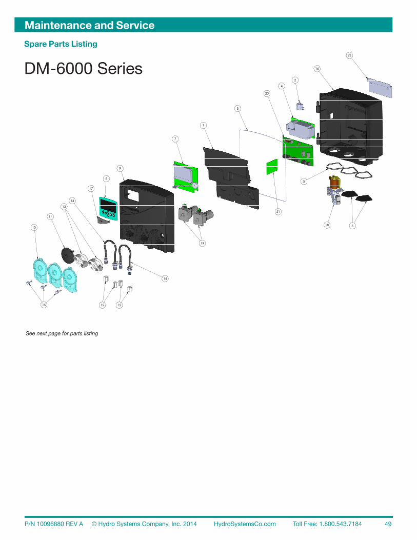
P/N 10096880 REV A © Hydro Systems Company, Inc. 2014 HydroSystemsCo.com Toll Free: 1.800.543.7184 49
Maintenance and Service
Spare Parts Listing
10
11
13
14
8
9
7
1
3
21
20
2
16
4
5
18 6
19
14
12
22
17
15 12
ITEM NO. PART NUMBER DESCRIPTION QTY.
1 10096809 PARTITION, POWER SUPPLY, 3 PUMP 1
2 10096233 Switch, Rocker, SPST 1
3 10096817 GASKET, DOOR, 3 PUMP 1
4 10096864 POWER SUPPLY, SBU58-108-H4 1
5 10096816-1 GASKET, SOLENOID 3
6 10096817 Cover, solenoid, black 27 10096853 PCB, Assy, DM Controller 1
8 10096857 Membrane switch, DM-6000, Teal 1
9 10096813 ENCLOSURE, FRONT, DM-6000, 3 PUMP 1
10 37-08602-06 Cover, pump, CP200, Teal 3
11 37-07098-05 Plug, Motor, Blank, Black 1
12 41-05567-00 Compression Nut & Sleeve, 1/4" 4
13 55-06281-03 Spinner, SST Shaft, Purchased 2
14 10096897 Rinse Tube, EPDM, 6.75", 1/4" Fixed X 1/4" Unfixed 2
15 27-08008-00 Screw, Captive 3
16 10096814 ENCLOSURE, REAR, DM-6000, 3 PUMP 1
17 10096811 COVER, USB, DM-6300, NA 118 03-06462-00 solenoid assembly with fittings 1
19 55-07308-01 Rinse motor, w/ HE and EMC 220 10096877 PCB, Assy, DM IC4 1
21 10096855 PCB, Assy, DM, Conductivity 1
22 37-08680-00 Hanger, Wall, Sprite, 400-Series 1
DM-6321DM-6000 Series
See next page for parts listing

P/N 10096880 REV A © Hydro Systems Company, Inc. 2014 HydroSystemsCo.com Toll Free: 1.800.543.7184 50
Maintenance and Service
Reference Number
Part Number Description
1 10096809 Partition Power Supply, 3 Product10096806 Partition Power Supply, 2 Product
2 10096233 Switch, Rocker, SPST3 10096817 Gasket, Door 3 Product
10096808 Gasket, Door 2 Product4 10097687 Kit, Power Supply Board5 10096816-1 Gasket, Solenoid6 10096817 Cover, Solenoid Port7 10097694 Kit, PCB Controller Board8 10096857 Membrane Switch, DM 6000 Teal9 10096813 Enclosure, Front DM 6000, 3 Product
10096847 Enclosure, Front DM 6000, 2 Product10 13-08706-06 Pump Cover, Front, Teal 11 37-07098-05 Plug, Motor, Blank, Black12 13-06563-00 Pump Tube Compression Nut w/ Sleeve, 1/4, (10 Pack)
13-06563-01 Pump Tube Compression Nut w/ Sleeve, 6 mm (10 Pack)13-06563-02 Pump Tube Compression Nut w/ Sleeve, 1/8, (10 Pack)
13 13-06396-00 Kit, Pump Spinner 14 13-06395-10 Pump Tube, Rinse, EPDM (Includes 1/4” Barb Fittings), 10 pack
13-06395-20 Pump Tube, Rinse, EPDM (Includes 1/4” and 1/8” Barb Fittings), 10 pack13-06395-30 Pump Tube, Rinse, EPDM (Includes 1/8” Barb Fittings), 10 pack13-06928-10 Pump Tube, Rinse, Silicone (Includes 1/4” Barb Fittings), 10 pack13-06928-20 Pump Tube, Rinse, Silicone (Includes 1/4” and 1/8” Barb Fittings), 10 pack13-06928-30 Pump Tube, Rinse, Silicone (Includes 1/8” Barb Fittings), 10 pack13-06399-10 Pump Tube, Detergent, EPDM (Includes 1/4” Barb Fittings), 10 pack
15 27-08008-00 Screw, Captive16 10096814 Enclosure, Rear, DM 6000, 3 Product
10096842 Enclosure, Rear, DM 6000, 2 Product17 10096811 Cover, USB Port, DM 6000, 3 Product
10096812 Cover, USB Port, DM 6000, 2 Product18 13-06397-00 Solenoid Valve Kit, 1/4” Fittings
13-06397-01 Solenoid Valve Kit, 6 mm Fittings13-06397-02 Solenoid Valve Kit, 5/16” (8 mm) Fittings
19 13-06523-01 Pump Motor, Rinse13-06524-01 Pump Motor, Detergent
20 10097690 Kit Interconnect Board DM 6000, 3 Product10097688 Kit Interconnect Board DM 6000, 2 Product
21 10097686 Kit, Conductivity Board Assy. DM600022 13-06647-00 Kit, Wall Bracket w/ Screws* 13-06529-00 Rinse Injection Fitting, Straight, Kynar, 1/8” NPT x 1/4” Tube* 13-06529-01 Rinse Injection Fitting, Straight, Kynar, 1/8” NPT x 1/8” (3mm) Tube* 13-06529-02 Rinse Injection Fitting, Straight, Kynar, 1/8” NPT x 6 mm Tube* 13-06531-00 Rinse Injection Fitting, 90° Elbow, Kynar, 1/8” NPT x 1/4” Tube* 13-06531-01 Rinse Injection Fitting, 90° Elbow, Kynar, 1/8” NPT x 1/8” (3 mm) Tube* 13-06531-02 Rinse Injection Fitting, 90° Elbow, Kynar, 1/8” NPT x 6mm” Tube* 13-03585-00 Detergent Injection Bulkhead connector 7/8” x 1/4 tube.
* Denotes items not shown

P/N 10096880 REV A © Hydro Systems Company, Inc. 2014 HydroSystemsCo.com Toll Free: 1.800.543.7184 51
Specifications and Warranty
Specifications
Dimensions
Size DM6200 series: 6.25”x9.00”x5.63” Size DM6300 series:8.57”x8.00”x5.63”
Weight DM6200 series: 4.69-5.23 lbs. Weight DM6300 series: 5.89-6.43 lbs
Power Requirements
Total Amperage draw during operation 60W Max.
General
Rinse Pump Flow Rate 11 oz/M
Detergent Pump Flow Rate 12 oz/M
Environmental
Pollution Degree 2
Temperature 10° - 50° C
Humidity 95% Relative Humidity
Ingress Protection Rating IP54
NOTE: Specifications subject to change without notice.
Limited Warranty Seller warrants solely to Buyer the Products will be free from defects in material and workmanship under normal use and service for a period of one year from the date of completion of manufacture. This limited warranty does not apply to (a) hoses; (b) and products that have a normal life shorter than one year; or (c) failure in performance or damage caused by chemicals, abrasive materials, corrosion, lightning, improper voltage supply, physical abuse, mishandling or misapplication. In the event the Products are altered or repaired by Buyer without Seller’s prior written approval, all warranties will be void. No other warranty, oral, express or implied, including any warranty of merchantablilty or fitness for any particular purpose, is made for these products, and all other warranties are hereby expressly excluded.
Seller’s sole obligation under this warranty will be, at Seller’s option, to repair or replace F.O.B. Seller’s facility in Cincinnati, Ohio any Products found to be other than as warranted.
Limitation of Liability Seller’s warranty obligations and Buyer’s remedies are solely and exclusively as stated herein. Seller shall have no other liability, direct or indirect, of any kind, including liability for special, incidental, or consequential damages or for any other claims for damage or loss resulting from any cause whatsoever, whether based on negligence, strict liability, breach of contract or breach of warranty.

P/N 10096880 REV A © Hydro Systems Company, Inc. 2014 HydroSystemsCo.com Toll Free: 1.800.543.7184 52
Index
AActivity Report .......................... 46–47Alarm Messages ....................... 41–42 See also entries for specific alarm typesAlarm Options ................................. 22Alarm Settings Menu ....................... 29Audible Alarm .................................... 4Automatic Initial Charge .................. 11BBenefits, product .............................. 4CCalibrate Pumps (Solenoid and Non-Solenoid) ......... 32Calibration ...................................... 32Change Squeeze Tube Time .......... 30Change Tank Alarm .................. 30, 41Clear Data Log ............................... 35Clear Setting, ................................. 36Compression Fitting ......................... 8Conductivity and Temperature Probe, for tank ................................. 4Conductivity Probe Faulty Alarm .... 41Conductivity Probe Range Setting (Probe Mode Only) ......................... 30Configuration Settings ................... 21Conveyor Machines ........ 7, 9, 12–14, 20–22, 25, 38, 43Conveyor Rack Time ...................... 21Cost per Rack ................................ 37DData Transfer ................................... 38Date and Time Set .................... 16, 36De-Lime Cycle ................................. 19Detergent Bulkhead Fitting ............... 7Detergent Control .................. 7, 12, 21Detergent Dose ......................... 14, 27Detergent Dose Interval ................... 27Detergent Feed................................ 12Detergent Initial Charge ................... 26Detergent Input Signal ...................... 4Detergent Overfeed Stop Alarm ...... 41Detergent Pump Speed ................... 24Detergent Set Point ......................... 24Detergent Signal .............................. 12Detergent Signal Wiring (probe and Probeless modes) ........................... 12Detergent Supply Tube ...................... 9Detergent Type ................................ 21Diagnostic Report ........................... 48Discharge Tube ................................. 8Display Live Conductivity ................ 23Display Live Rinse Temperature ...... 23Door Machines ...10–14, 20–26, 38, 43Download Productivity Report, ....... 20EEdit Account Name ......................... 36Edit Company Name ...................... 36Edit Installer Password .................... 35Edit Machine Name ......................... 36Edit Manager Password .................. 35Electrical Connections .................... 11Electric Cost/KWH .......................... 37Enter Product Cost .......................... 33Enter Set Point ................................ 24External Solenoid Enable ................ 37External Solenoid Output Signal, for rinse dissolver ................................... 4FFlush Manifold Connection ............... 9Full KW Power Usage ..................... 37HHome Screen, ................................. 17
IIdle KW Power Usage ..................... 38Initial Charge ............................. 14, 22Initial System Setup ........................ 35Installation diagram for ...................... 5 electrical ................................ 10–12 mechanical ................................ 6–9Installer Password ........................... 20Installer Service ............................... 30KKeypad ............................................ 17LLanguage Selection......................... 16LCD Display ...................................... 4Low Detergent Alarm ...................... 12Low Detergent Alarm Delay/Detergent Overfeed Stop Alarm ....................... 29Low Detergent Alarm Threshold 15, 28Low Rinse Temperature Alarm ........ 41Low Rinse Temp Setting ................. 30MMachine Clean Alarm ...................... 41Machine Clean Alarm Setting (Probe and Probeless) ..................... 29Machine Type .................................. 21Main Power Wiring .......................... 11Maintenance and Service ................ 49Manager Reports ............................ 20Manual Initial Charge....................... 19Manually Add Product ..................... 24Max Detergent Time ........................ 19Menus ............................................. 18Motor/solenoid drive outputs for detergent and rinse ........................... 4Mounting Bracket .............................. 6NName Pumps .................................. 31Names, edit account, machine, and company ......................................... 36Navigation to User/Program Menus 18OOperating Modes Probe Operation Mode ........ 12–13 Probeless Operation Mode .. 14–15PParts, list of ................................49-50See also entries for specific partsPassword .................................. 20, 35Poly tubing ........................................ 9Power Consumption ....................... 38Power Saver .................................... 18Prime Pumps ................................... 31See also User PrimeProbe Mounting ................................ 6 (Probe Operation Only)Probe Not Calibrated Alarm ............ 42Probe Operation Mode .............. 12–13Probe Wiring .................................... 10Product Benefits ............................... 4Productivity Report ................... 20, 43Programming Menus, Screens, and Setup ......................................... 16–40Program Settings ............................ 24(Probe Mode Only) Program Settings ............................ 26(Probeless Mode Only) Pulse Feed ...................................... 13Probeless Operation Mode ........14-15Pulse Feed Settings ........................ 21Pump Alarm .................................... 42Pump Calibration ...................... 30–31Pump Jam Alarm ............................. 42Pump Supply Tubes .......................... 9
RRack Counts .............................. 13, 15Read Setup ..................................... 39Reports activity ................................. 46–47 diagnostic .................................. 48 productivity ................................ 43 settings ................................ 44–45 write ........................................... 39Rinse and Detergent Supply ............. 9Rinse Control ............................. 12, 15Rinse Delay Time .......... 13, 15, 25, 28Rinse Feed Option ........ 13, 15, 25, 28Rinse Injection Fitting ........................ 7Rinse input signal .............................. 4Rinse Pump ..................................... 13Rinse Pump Speed ................... 24, 27Rinse Saver ............................... 13, 15Rinse Signal Wiring ......................... 12SService Pumps ................................ 31Set LCD Contrast ............................ 35Set Pump Install .............................. 34Set Pump Product ........................... 34Set Pump Type ................................ 34Sets Units of Measure ..................... 22Settings Report ......................... 44–45Signal Display Enable ...................... 37Solenoid Water Feed ......................... 7Spare Parts Listing .....................49-50Specifications, system ...................... 4Specifications and Warranty ........... 51Squeeze Tube Change Alarm .......... 41Start-up Splash Screen ................... 16Supply Tube ...................................... 9Symbols .......................................... 18TTank Change Interval ................. 13, 15Tank fill input signal ........................... 4Third Product Pump Speed ...... 26, 28Third Product Run ........................... 23Time ................... See Date and Time SetTotal Cost ........................................ 38Tube Replacement Date .................. 33UUpdate Firmware ............................. 40USB type A ........................................ 4User Menus ..................................... 18User Prime ...................................... 23User Prime Pumps .......................... 18Use Tank Reading ........................... 24VView Amount Pumped ..................... 34View Calibration .............................. 32View Pump Configuration................ 31View Serial Number ......................... 37View Software ID ............................. 37WWall Mounting ................................... 6Warranty, Specifications and........... 51Water Unit Cost ............................... 37Water Volume/Wash ........................ 38Write Reports .................................. 39Write Setup ..................................... 40

DE
TE
RG
EN
T C
NT
RL
PR
OB
E
PR
OB
ELE
SS
<B
AC
K
EN
TER
>
2.2
.1.1
.1
2.2
.1.1
.5
2.2
.1.1
.9
Hom
e S
cree
n
AC
CE
SS
ED
BY
PR
ES
SIN
G
AN
Y O
THE
R N
AV
IGAT
ION
K
EY
1.0
1.1
1.2
1.3
1.4
2.0
2.1
2.2
NO
VA C
ON
TR
OLS
Rac
ks:
0000
0 P
RO
BE
Con
d:
000
WTe
mp
:000
Set
pt:
00
0 R
Tem
p:0
00S
ignl
: 1
0
Pum
p:
DE
T
R
IN S
AN
Ala
rm:
*
*
LO
WD
ET
**
US
ER
ME
NU
US
ER
PR
IME
PU
MP
SD
E-L
IME
CY
CLE
MA
X D
ETE
RG
EN
T TI
ME
MA
NU
AL
INIT
IAL
CH
RG
AC
CE
SS
ED
BY
PR
ES
SIN
G
BA
CK
KE
Y
SE
T P
RIM
E P
UM
P
P1
DE
TER
GE
NT
P2
RIN
SE
P3
SA
NIT
IZE
R
PR
IME
P1
DE
TER
GE
NT
<E
XIT
S
TAR
T/S
TOP
>
SE
T P
RIM
E P
UM
P
DIS
AB
LED
<E
XIT
STA
RT
DE
-LIM
ETH
IS W
ILL
STO
P
ALL
OP
ER
ATIO
N
CO
NTI
NU
E?
<E
XIT
S
TAR
T/S
TOP
>
DE
-LIM
E C
YC
LE
TIM
E R
EM
AIN
ING
: 09
:59
<E
XIT
MA
X D
ET
TIM
E
05:0
0 M
M:S
S
<E
XIT
R
ES
ET>
MA
NU
AL
CH
AR
GE
DO
YO
U W
ISH
TO
STA
RT
MA
NU
AL
INIT
IAL
CH
AR
GE
?
<B
AC
K
EN
TER
>
MA
NU
AL
CH
AR
GE
TIM
E R
EM
AIN
ING
: 19
9 S
EC
<E
XIT
1.1.
1
1.2.
1
1.4.
1
1.1.
2
PR
OG
RA
M M
EN
UM
AN
AG
ER
RE
PO
RTS
INS
TALL
ER
ME
NU
MG
R P
AS
SW
OR
D
<01
23>
<B
AC
K
EN
TER
>
RE
PO
RT
DA
TE
FR
OM
: <20
12-0
1-01
>
<B
AC
K
EN
TER
>
RE
PO
RT
DA
TE
TO
:
<20
12-0
5-28
>
<B
AC
K
EN
TER
>
RE
PO
RT
NA
ME
<R
EP
OR
T>
<B
AC
K
EN
TER
>
INS
TL
PAS
SW
OR
D
<01
234>
<B
AC
K
EN
TER
>
INS
TALL
ER
ME
NU
CO
NFI
G S
ETT
ING
SP
RO
GR
AM
SE
TTIN
GS
ALA
RM
SE
TTIN
GS
INS
TALL
ER
SE
RV
ICE
INIT
IAL
SY
STE
M S
ETU
PD
ATA
TR
AN
SFE
R
CO
NFI
G S
ET
TIN
GS
DE
TER
GE
NT
CN
TRL
MA
CH
INE
TY
PE
DE
TER
GE
NT
TYP
EA
LAR
M O
PTI
ON
UN
ITS
OF
ME
AS
UR
E<
AU
TO S
WIT
CH
MO
DE
>
DIS
P L
IVE
CO
ND
DIS
P R
INS
E T
EM
PU
SE
R P
RIM
E P
UM
PS
INIT
IAL
CH
AR
GE
<C
ON
V R
AC
K T
IME
><
PU
LSE
FE
ED
><
THIR
D P
RO
DU
CT>
MA
CH
INE
TY
PE
DO
OR
C
ON
VE
YO
R
ALT
ER
NAT
E D
OO
R<
BA
CK
E
NTE
R>
DE
TE
RG
EN
T T
YP
E
LIQ
UID
C
AP
SU
LE
<B
AC
K
EN
TER
>
2.1.
1
2.2.
1
2.2.
1.1
2.1.
22.
1.3
2.2.
1.1.
2 2.
2.1.
1.3
2.2.
1.1.
4
ALA
RM
OP
TIO
N
OFF
IN
TER
NA
L E
XTE
RN
AL
BO
TH
<B
AC
K
EN
TER
>
UN
ITS
- M
EA
SU
RE
SA
E/I
MP
ER
IAL
(LB
/OZ
)M
ETR
IC (K
G/M
L)
<B
AC
K
EN
TER
>
CO
NV
EY
OR
TIM
E
<00
SE
C>
<B
AC
K
EN
TER
>
DIS
P L
IVE
CO
ND
EN
AB
LE
DIS
AB
LE
<B
AC
K
EN
TER
>
DIS
P R
INS
E T
EM
P
EN
AB
LE
DIS
AB
LE
<B
AC
K
EN
TER
>
2.2.
1.1.
6 2.
2.1.
1.7
2.2.
1.1.
8
US
ER
PR
IME
D
ISA
BLE
EN
AB
LE
LIM
ITE
D 3
0 S
EC
___
_
<B
AC
K
EN
TER
>
INIT
IAL
CH
AR
GE
AU
TOM
ATIC
M
AN
UA
L
<B
AC
K
EN
TER
>
PU
LSE
FE
ED
OFF
-N
O P
ULS
E F
EE
D
1-O
N
9-O
FF 5
0% S
PT
1-O
N
9-O
FF 7
0% S
PT
2-O
N
6-O
FF 5
0% S
PT
2-O
N
6-O
FF 8
0% S
PT
(DE
FAU
LT)
4-O
N
4-O
FF 7
0% S
PT
6-O
N
4-O
FF 8
0% S
PT
6-O
N
1-O
FF 9
0% S
PT
3RD P
RO
DU
CT
RU
N
RIN
SE
D
ETE
RG
EN
T
<B
AC
K
EN
TER
>
2.2.
1.1.
10
2.2.
1.1.
11
2.2.
1.1.
12
2.2
.1.1
.13
2.2.
1.2,
2.2
.1.3
, 2.2
.1.4
, 2.2
.1.5
, 2.2
.1.6
>
>>
CO
NT
INU
E O
N F
OL
LO
WIN
G P
AG
ES
AU
TO
SW
ITC
H M
OD
E
EN
AB
LE
DIS
AB
LE
<B
AC
K
EN
TER
>

2.2.
1.2.
1 P
L
2.2.
1.2.
2 P
L
2.2.
1.2.
3 P
L
2.2.
1.2.
4 P
L
2.2.
1.2.
5 P
L 2.
2.1.
2.5.
1 P
L 2.
2.1.
2.5.
2 P
L
2.2.
1.2.
6 P
L
2.2.
1.2.
7 P
L
2.2.
1.2.
8 P
L 2.
2.1.
2.8.
1 P
L 2.
2.1.
2.8.
2 P
L
DE
T IN
IT C
HA
RG
E
012
SE
C
<B
AC
K
EN
TER
>2.
2.1.
2.2
2.2.
1.2.
2.1
2.2.
1.2.
2.2
2.2.
1.2.
3
2.2.
1.2.
4
2.2.
1.2.
5 2.
2.1.
2.5.
1 2.
2.1.
2.5.
2
2.2.
1.2
P (
PR
OB
E D
ETE
RG
EN
T C
ON
TRO
L)
PR
OG
SE
TT
ING
S D
ETE
RG
EN
T S
ETP
NT
DE
TER
GE
NT
SP
EE
D
RIN
SE
PU
MP
SP
EE
DR
INS
E F
EE
D O
PTI
ON
RIN
SE
DE
LAY
TIM
E TH
IRD
PR
OD
SP
EE
D
DE
T S
ET
PO
INT
MA
NU
AL
AD
D P
RO
D
EN
TER
SE
T P
OIN
TU
SE
TA
NK
RE
AD
ING
TAN
K R
EA
DIN
G:
000
SE
T P
OIN
T:
00
0
MA
NU
AL
AD
DTA
NK
RE
AD
ING
: 0
00
<E
XIT
S
TAR
T/S
TOP
>
EN
TE
R S
ET
PN
T
<00
0>
<B
AC
K
EN
TER
>
RIN
SE
PU
MP
SP
D
20.5
RP
M
TO T
ES
T
<B
AC
K
EN
TER
>
RIN
SE
PU
MP
SP
D
00.0
RP
M
<B
AC
K
EN
TER
>
TE
ST
PU
MP
20
.5 R
PM
<E
XIT
S
TAR
T/S
TOP
>
2.2.
1.2.
1 2.
2.1.
2.1.
1 2.
2.1.
2.1.
2
RIN
SE
FE
ED
OP
T
RIN
SE
ON
RIN
SE
R
INS
E O
N D
ET
<B
AC
K
EN
TER
>
RIN
SE
DE
LAY
TIM
E
<00
0 S
EC
>
<
BA
CK
EN
TER
>
3RD P
RO
DU
CT
SP
D
110
RP
M
TO T
ES
T
<B
AC
K
EN
TER
>
3RD P
RO
DU
CT
SP
D
00.0
RP
M
<B
AC
K
EN
TER
>
3RD P
RO
DU
CT
SP
D
110
RP
M
TO T
ES
T
<B
AC
K
EN
TER
>
PR
OG
SE
TT
ING
SD
ET
INIT
IAL
CH
AR
GE
DE
TER
GE
NT
DO
SE
DE
T D
OS
E IN
TRVA
LLO
W D
ET
THR
SH
LDR
INS
E P
UM
P S
PE
ED
RIN
SE
FE
ED
OP
TIO
NR
INS
E D
ELA
Y T
IME
3RD P
RO
D P
UM
P S
PE
ED
2.2.
1.2
PL
(PR
OB
ELE
SS
DE
TER
GE
NT
CO
NTR
OL)
DE
T D
OS
E
02 S
EC
<B
AC
K
EN
TER
>
DE
T D
OS
E IN
TR
VL
1 R
AC
KS
<B
AC
K
EN
TER
>
LOW
DE
T T
HR
SH
LD
00 R
AC
KS
<B
AC
K
EN
TER
>
RIN
SE
PU
MP
SP
D
20.5
RP
M
TO T
ES
T
<B
AC
K
EN
TER
>
RIN
SE
PU
MP
SP
D
00.0
RP
M
<B
AC
K
EN
TER
>
TE
ST
PU
MP
20
.5 R
PM
<E
XIT
S
TAR
T/S
TOP
>
RIN
SE
FE
ED
OP
T
RIN
SE
ON
RIN
SE
R
INS
E O
N D
ET
<B
AC
K
EN
TER
>
RIN
SE
DE
LAY
TIM
E
<00
0 S
EC
>
<
BA
CK
EN
TER
>
3RD P
RO
DU
CT
SP
D
110
RP
M
TO T
ES
T
<B
AC
K
EN
TER
>
3RD P
RO
DU
CT
SP
D
00.0
RP
M
<B
AC
K
EN
TER
>
TE
ST
PU
MP
11
0 R
PM
<E
XIT
S
TAR
T/S
TOP
>

2.2.
1.3
2.2.
1.3.
1.
2.2.
1.3.
1.1
2.2.
1.3.
1.1.
1
2.
2.1.
3.2
2.2.
1.3.
2.1
2.
2.1.
3.3
2.2.
1.3.
3.1
2.2.
1.3.
3.2
2.
2.1.
3.4
2.
2.1.
3.5
2.
2.1.
3.6
ALA
RM
SE
TT
ING
SLO
W D
ET/
OV
ER
FEE
DM
AC
HIN
E C
LEA
NP
RO
BE
FA
ULT
YC
HA
NG
E S
QZ
TU
BE
CH
AN
GE
TA
NK
LOW
RIN
SE
TE
MP
EN
AB
LE A
LAR
M
DIS
AB
LE
EN
AB
LE
<B
AC
K
EN
TER
>
LOW
DE
T A
LAR
M
RA
CK
S R
UN
LO
W:
0A
LAR
M S
ETT
ING
: 0
<B
AC
K
EN
TER
>
LOW
DE
T A
LAR
M
0
<B
AC
K
EN
TER
>
EN
AB
LE A
LAR
M
DIS
AB
LE
EN
AB
LE
<B
AC
K
EN
TER
>
MA
CH
CLE
AN
RK
10
0
<B
AC
K
EN
TER
>
CO
ND
PR
OB
E M
IN
00
0
<B
AC
K
EN
TER
>
CO
ND
PR
OB
E M
AX
00
0
<B
AC
K
EN
TER
>
PR
OB
E F
AU
LT R
AC
K
00
0 R
AC
KS
<B
AC
K
EN
TER
>
CH
G T
AN
K R
AC
K
00
RA
CK
S
<B
AC
K
EN
TER
>
CH
G T
UB
E T
IME
18
0 D
AYS
<B
AC
K
EN
TER
>
LOW
RIN
SE
TE
MP
15
0 D
EG
F
<B
AC
K
EN
TER
>

2.2.
1.4.
1.1
2.2.
1.4.
1.2
2.2.
1.4.
1.2.
1
2.2.
1.4.
1.3
2.2.
1.4.
1.3.
1 2.
2.1.
4.1.
3.2
2.2.
1.4.
1.3.
2.1
2.2.
1.4.
1.3.
2.1.
1
2.2.
1.4.
1.4
2.2.
1.4.
1.4.
1
2.2.
1.4.
1.5
2.2.
1.4.
1.5.
1
2.2.
1.4.
1.6
2.2.
1.4.
1.6.
1
2.2.
1.4.
1.7
2.2.
1.4.
1.7.
1
2.2.
1.4.
1.8
2.2.
1.4.
1.8.
1
2.2.
1.4.
1.9
2.2.
1.4.
1.9.
1
INS
TALL
ER
SE
RV
ICE
S
ER
VIC
E P
UM
PS
VIE
W A
MO
UN
T P
UM
PE
DC
LEA
R D
ATA
LO
G
SE
RV
ICE
PU
MP
S
VIE
W P
UM
P C
ON
FIG
N
AM
E P
UM
PS
P
UM
P C
ALI
BR
ATIO
N
PR
IME
PU
MP
E
NTE
R P
RO
DU
CT
CO
STS
TU
BE
RE
PLA
CE
ME
NT
SE
T P
UM
P T
YP
ES
ET
PU
MP
PR
OD
UC
T S
ET
PU
MP
INS
TALL
VIE
W P
UM
P C
ON
FIG
TYP
E
PR
OD
IN
ST
P1
SO
L D
ET
YE
SP
2 P
UM
P
RIN
Y
ES
P3
PU
MP
S
AN
N
O
NA
ME
PU
MP
(P1)
<
DE
TER
GE
NT>
<B
AC
K
EN
TER
>
SE
LEC
T P
UM
P
P1
DE
TER
GE
NT
P2
RIN
SE
PU
MP
CA
LIB
RA
TIO
N
V
IEW
CA
LIB
RAT
ION
CA
LIB
RAT
E
PU
MP
CA
LIB
RA
TIO
N
P1
DE
TER
GE
NT
0.30
0P
2 R
INS
E
0.12
5P
3 S
AN
ITIZ
ER
0.
200
PU
MP
CA
LIB
RA
TIO
N
P1
DE
TER
GE
NT
P2
RIN
SE
P
3 S
AN
ITIZ
ER
CA
LIB
RA
TE
P
1 D
ETE
RG
EN
T
STO
P P
UM
P A
T 8
OZ
. W
AR
NIN
G! P
LAC
E
CO
NTA
INE
R A
T O
UTP
UT!
<E
XIT
S
TAR
T/S
TOP
>
CA
LIB
RAT
E M
L R
EV
P1
DE
TER
GE
NT
00
0.00
<B
AC
K
EN
TER
>
SE
T P
RIM
E P
UM
P
P1
DE
TER
GE
NT
P2
RIN
SE
P3
SA
NIT
IZE
R
PR
IME
P
1 D
ETE
RG
EN
T
<E
XIT
S
TAR
T/S
TOP
>
P3
CO
ST
S/G
AL
<
0000
.00>
<B
AC
K
EN
TER
>
PR
OD
UC
T C
OS
TS
P1
DE
TER
GE
NT
P
2 R
INS
E
P3
SA
NIT
IZE
R
TU
BE
RE
PLA
CE
ME
NT
P
2 R
INS
EP
3 S
AN
ITIZ
ER
P3
DA
TE
CH
AN
GE
D
<
2013
-01-
05>
<O
K
EX
IT>
SE
LEC
T P
UM
P P
1 D
ETE
RG
EN
T P
2 R
INS
EP
3 S
AN
ITIZ
ER
SE
T P
UM
P T
YP
E S
OLE
NO
IDP
UM
P
<B
AC
K
EN
TER
>
SE
LEC
T P
UM
P P
1 D
ETE
RG
EN
T P
2 R
INS
EP
3 S
AN
ITIZ
ER
SE
T P
RO
DU
CT
DE
T R
INS
E
SA
N
<B
AC
K
EN
TER
>
PU
MP
INS
TALL
N
OY
ES
<B
AC
K
EN
TER
>
SE
LEC
T P
UM
P P
1 D
ETE
RG
EN
T P
2 R
INS
EP
3 S
AN
ITIZ
ER
PU
MP
ED
(GA
L.)
P1
DE
TER
GE
NT
18.5
P2
RIN
SE
26.2
P3
SA
NIT
IZE
R
38.0
CLE
AR
DA
TA L
OG
WA
RN
ING
! ALL
LO
GS
W
ILL
BE
CLE
AR
ED
<B
AC
K
EN
TER
>
2.2.
1.4
2.2
.1.4
.1.
2.
2.1.
4.2
2.
2.1.
4.3

2.2.
1.5.
1 2.
2.1.
5.9
2.
2.1.
17
2.2.
1.5.
2 2.
2.1.
5.10
2.
2.1.
5.10
.1
2.2.
1.18
2.2.
1.5.
3 2.
2.1.
5.11
2.2.
1.19
2.2.
1.5.
4 2.
2.1.
5.12
2.2.
1.5.
5 2.
2.1.
5.13
2.2.
1.5.
6 2.
2.1.
5.14
2.2.
1.5.
7 2.
2.1.
5.15
2.2.
1.5.
8 2.
2.1.
5.16
SY
ST
EM
SE
TU
P E
DIT
INS
T PA
SS
WO
RD
___
_
ED
IT M
GR
PA
SS
WO
RD
ED
IT A
CC
OU
NT
NA
ME
ED
IT M
AC
HIN
E N
AM
EE
DIT
CO
MPA
NY
NA
ME
ED
IT M
AC
H N
AM
EE
IDIT
CO
NTA
CT
NA
ME
SET
LC
D C
ON
TRA
ST
SET
DAT
E &
TIM
EC
LEA
R S
ETTI
NG
SV
IEW
SO
FTW
AR
E ID
VIE
W S
ER
IAL
NU
MS
IGN
AL
DS
P E
NA
BLE
EXI
T S
OL
ENA
BLE
ELE
CTR
IC C
OS
T/K
WH
WAT
ER C
ST/
K U
NIT
SFU
LL K
W P
WR
US
AG
EID
LE K
W P
WR
US
AG
EW
ATER
VO
L/W
AS
HC
ON
D R
AN
GE
MA
X
INS
TL
PAS
SW
OR
D
<01
23>
<B
AC
K
EN
TER
>
MG
R P
AS
SW
OR
D
<01
23>
<B
AC
K
EN
TER
>
AC
CO
UN
T N
AM
E
<R
ES
TAU
RA
NT-
087>
<B
AC
K
EN
TER
>
MA
CH
INE
NA
ME
<K
ITC
HE
N 0
1>
<B
AC
K
EN
TER
>
CO
MPA
NY
NA
ME
<N
OVA
CO
NTR
OLS
>
<B
AC
K
EN
TER
>
2.2.
1.5
ED
IT M
AN
F N
AM
E
<
>
<B
AC
K
EN
TER
>
ED
IT C
ON
TAC
T N
AM
E
<
>
<B
AC
K
EN
TER
>
LCD
CO
NT
RA
ST
5 0
<B
AC
K
EN
TER
>
DA
TE
& T
IME
<00
00-0
0-00
> <
00:0
0>
YY
YY-
MM
-DD
H
H:M
M
<B
AC
K
EN
TER
>
CLE
AR
SE
TT
ING
S
WA
RN
ING
! ALL
SE
TUP
S
WIL
L B
E C
LEA
RE
D T
O
FAC
TOR
Y D
EFA
ULT
S!
<B
AC
K
EN
TER
>
CLE
AR
SE
TT
ING
S
AR
E Y
OU
SU
RE
?
<B
AC
K
EN
TER
>
SO
FTW
AR
E ID
Ant
ares
DM
6000
P
/N: N
N-N
NN
NN
-NN
N
RE
VN
NN
NN
<B
AC
K
EN
TER
>
SE
RIA
L N
UM
BE
R
1234
5678
9012
34
SIG
NA
L D
SP
EN
AB
LE
DIS
AB
LE
EN
AB
LE
<B
AC
K
EN
TER
>
EX
T S
OL
EN
AB
LE
0
<B
AC
K
EN
TER
>
ELE
CTR
IC C
ST/
KW
H
000
0.00
<B
AC
K
EN
TER
>
WAT
ER
CS
T/K
UN
ITS
000
0.00
<B
AC
K
EN
TER
>
FULL
KW
PW
R
000
<B
AC
K
EN
TER
>
IDLE
KW
PW
R
000
<B
AC
K
EN
TER
>
WAT
ER
VO
L/W
AS
H
000
<B
AC
K
EN
TER
>

2.2.
1.6
2.2.
1.6.
1 2.
2.1.
6.1.
1 2.
2.1.
6.1.
2 2.
2.1.
6.1.
2
2.2.
1.6.
2 2.
2.1.
6.2.
1 2.
2.1.
6.2.
2
2.2.
1.6.
3 2.
2.1.
6.3.
1
2.2.
1.6.
4 2.
2.1.
6.4.
1
DA
TA T
RA
NS
FER
W
RIT
E R
EP
OR
TSR
EA
D S
ETU
PW
RIT
E S
ETU
PU
PD
ATE
FIR
MW
AR
ER
EP
OR
T D
AT
E
FRO
M: 20
13-0
1-01
<B
AC
K
EN
TER
>
RE
PO
RT
DA
TE
TO
:
2013
-05-
28
<B
AC
K
EN
TER
>
WA
RN
ING
N
AM
E E
XIS
TS
OV
ER
WR
ITE
EX
ISTI
NG
FI
LE N
AM
E?
<B
AC
K
EN
TER
>
RE
PO
RT
NA
ME
<U
VW
XY
Z>
INS
ER
T U
SB
DR
IVE
<B
AC
K
EN
TER
>
SE
TU
P F
ILE
S
TD D
OO
R S
ETU
PS
TD C
ON
VE
YO
RB
OB
S B
UR
GE
RS
PU
B A
ND
GR
UB
JOE
S C
AFE
WA
RN
ING
TH
IS W
ILL
OV
ER
WR
ITE
E
XIS
TIN
G S
ETT
ING
S
AN
D F
OR
MU
LAS
<B
AC
K
EN
TER
>
ER
RO
R
UN
AB
LE T
O
RE
AD
FIL
E
<B
AC
K
EN
TER
>
WA
RN
ING
NA
ME
EX
ISTS
! O
VE
RW
RIT
E E
XIS
TIN
G
FILE
?
<B
AC
K
EN
TER
>
SE
TU
P F
ILE
<
V W
X Y
Z >
IN
SE
RT
US
B D
RIV
E <
BA
CK
E
NTE
R>
UP
DAT
E F
IRM
WA
RE
S
TOP
!!! D
O N
OT
PR
OC
EE
D W
ITH
OU
T P
C U
PD
ATE
PR
OG
RA
M
<
BA
CK
EN
TER
>
UP
DAT
E F
IRM
WA
RE
C
ON
NE
CT
PC
AN
D
BE
GIN
UP
DAT
E
<
BA
CK
EN
TER
>
3.0
ALA
RM
SE
CT
ION
ALA
RM
D
ETE
RG
EN
T O
VE
RFE
ED
S
TOP
! – C
HA
NG
E T
HE
P
RO
DU
CT
CO
NTA
INE
RB
EFO
RE
CLE
AR
ING
<
CLE
AR ALA
RM
M
AC
HIN
E C
LEA
N!
– P
ER
FOR
M A
DE
-LIM
EC
YC
LE O
N T
HE
WA
SH
ER
<
CLE
AR ALA
RM
C
ON
D P
RO
BE
FA
ULT
Y! –
CH
EC
K D
ET
PR
OB
E F
OR
DA
MA
GE
OR
FO
ULI
NG
<
CLE
AR ALA
RM
C
ON
D P
RO
BE
FA
ULT
Y! –
DO
YO
U W
ISH
TO
SW
ITC
H
TO P
RO
BEL
ESS
MO
DE
<
YE
S
NO
>
ALA
RM
S
QU
EE
ZE
TU
BE
S N
EE
D
TO B
E C
HA
NG
ED
!
<
CLE
AR ALA
RM
C
HA
NG
E T
AN
K!
RA
CK
S R
UN
SIN
CE
LA
ST
INIT
IAL
FILL
HA
S B
EE
N
EX
CE
ED
ED
<
CLE
AR
ALA
RM
LO
W R
INS
E
TEM
PE
RAT
UR
E
<
CLE
AR
3.1
3.2
3.3.
3.4
3.5
3.6
ALA
RM
P
UM
P 1
JA
M
CH
EC
K D
ISP
EN
SE
R
<
CLE
AR ALA
RM
C
ON
DU
CTI
VIT
Y P
RO
BE
N
OT
CA
LIB
RAT
ED
<
CLE
AR
3.7
3.8
3.9


