1
AN AC COUPLED PV/WIND/DIESEL MICROGRID SYSTEM IMPLEMENTED IN A REMOTE ISLAND
IN THE REPUBLIC OF MALDIVES

2
The President inaugurates the Hybrid Renewable Energy Pilot Project implemented at North Thiladhunmathi Atoll Uligamu in the Republic of Maldives.
Monday, January 7, 2008
The President today inaugurated the Hybrid Renewable Energy Pilot Project implemented at North Thiladhunmathi Atoll Uligamu. Speaking at the official launching of the project, the President noted that this was the world’s first Hybrid AC Coupled Renewable Energy Micro Grid, and said that the Government appreciated the initiative taken by STO and Maldive Gas to invest in the project. He also emphasized the importance of such a project, considering the global concerns of climate change and rising fuel prices.
The President thanked Daily Life Renewable Energy of Singapore and the US Government for the technical expertise and material support they contributed to this project. The President noted that Uligamu was a historically significant island and that it had been isolated and re-populated several times over the past.
At the ceremony, the President was presented with an honorary plaque to symbolize the importance he attaches to the environment by the Chairman of STO’s Board of Directors, Mr. Ahmed Mohamed. In his welcome address, Mr. Ahmed Mohamed noted that the President attaches a high priority to sustainable development and environmental conservation.
Professor C.V Nayar of Australia’s Curtin University of Technology and Director of Regen Power presented practical information on the project.
Speaking at the ceremony, the Deputy Minister of Environment, Energy and Water, Mr. Abdul Razzaq Idrees highlighted that Uligamu was the first island to implement such a project.
The US Ambassador, Mr. Robert Blake Jr. emphasized the necessity of this project at such a time as now when fuel prices are on the rise. He also said that this project would give the people of Maldives an opportunity to utilize solar energy.

3
Contents 1. Introduction ...................................................................................................................................... 4
2. Wind and Solar Resources ............................................................................................................... 4
2.1. Wind Resource Information ................................................................................................................................. 4
2.2. Solar Resource Information ................................................................................................................................. 5
3. Existing Electrical System ................................................................................................................ 5
4. System Sizing .................................................................................................................................. 7
5. System Performance ........................................................................................................................ 9
6. Conclusion ........................................................................................................................................ 9
7. References ..................................................................................................................................... 11
7. Contact Us ...................................................................................................................................... 11
4
1. Introduction Most small islands around the world today are dependent on imported fossil fuels for most of their energy requirements. The Republic of Maldives is one such island nation with 1,192 islands with a land area of about 300 km2, formed on a chain of 26 coral reef atolls in the Indian Ocean. The electricity in the Maldives is exclusively produced by diesel generators run on every inhabited island. The use of diesel generators to provide electricity is one of the most expensive and environmentally detrimental ways of generating electricity. Although these islands produce only a tiny fraction of global greenhouse gas emissions, they are among the most vulnerable to the effects of climate change since around 80 percent of the total landmass of the Maldives is less than 1 meter above sea level. The authors were involved in a feasibility study to survey and then design an electricity generation system for three islands selected for the pilot phase of a long term program of deployment of solar and wind systems in stand alone diesel generators. The names and location of the islands are given in Table 1.
Table -1. Location information.
Location Latitude LongitudeUligam 7’ 05” N 72’ 55” W
Raimandhoo 3’05” N 73’40” WKondey 0’40” N 73’50’W
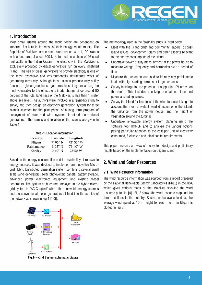
Based on the energy consumption and the availability of renewable energy sources, it was decided to implement an innovative Micro-grid Hybrid Distributed Generation system combining several small scale wind generators, solar photovoltaic panels, battery storage, advanced power electronics equipment and existing diesel generators. The system architecture employed in the hybrid micro-grid system is “AC Coupled” where the renewable energy sources and the conventional diesel generators all feed into the ac side of the network as shown in Fig.1 [1-3].
Fig.1-Hybrid System schematic diagram
The methodology used in the feasibility study is listed below: • Meet with the island chief and community leaders, discuss
island issues, development plans and other aspects relevant to the energy consumption of the island
• Undertake power quality measurement at the power house to measure voltage, frequency and harmonics over a period of time
• Measure the instantaneous load to identify any problematic loads with high starting currents or large demands
• Survey buildings for the potential of supporting PV arrays on the roof. This includes checking orientation, slope and potential shading issues.
• Survey the island for locations of the wind turbines taking into account the most prevalent wind direction onto the island, the distance from the power house, and the height of vegetation around the turbines.
• Undertake renewable energy system planning using the software tool HOMER and to analyse the various options paying particular attention to the cost per unit of electricity consumed, fuel saved and initial capital requirements.
This paper presents a review of the system design and preliminary results based on the implementation on Uligam Island.
2. Wind and Solar Resources
2.1. Wind Resource Information
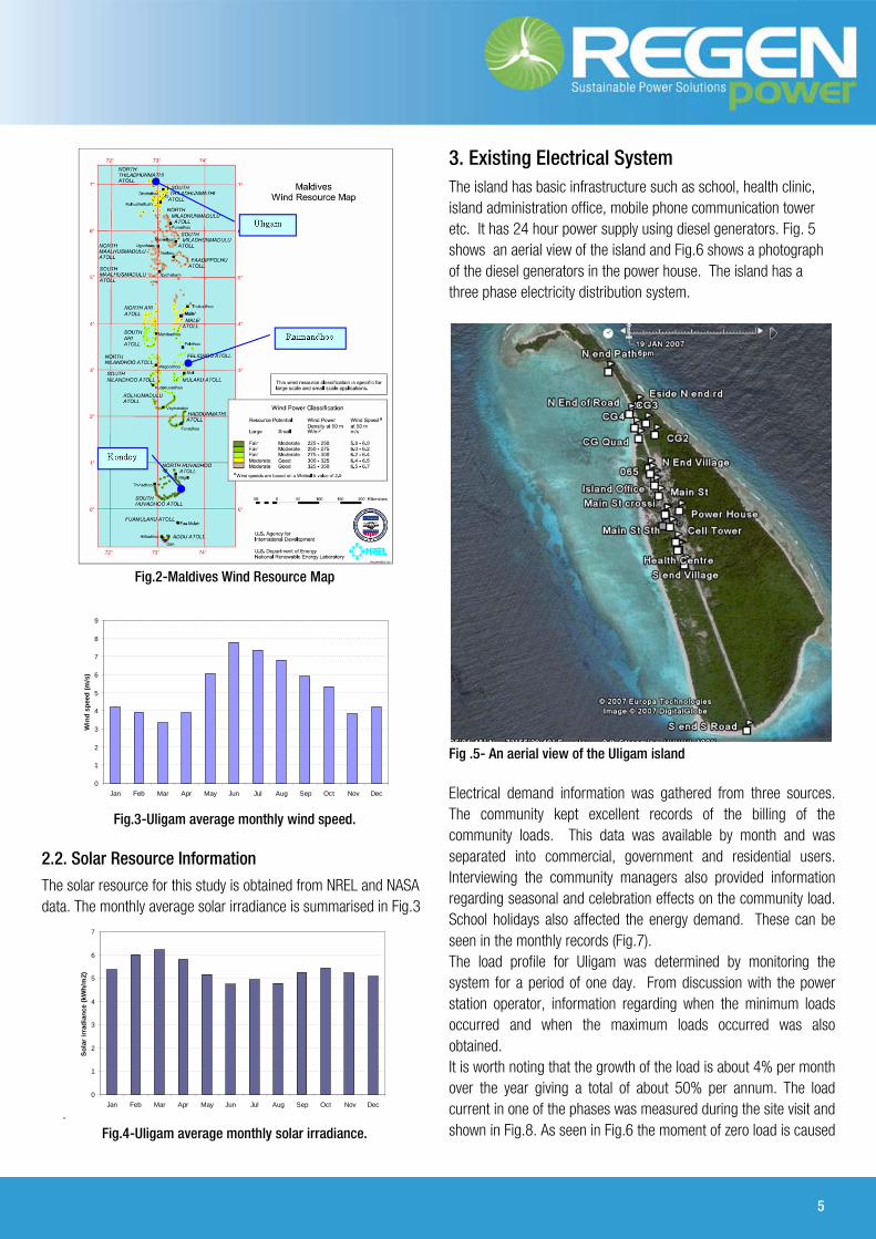
The wind resource information was sourced from a report prepared by the National Renewable Energy Laboratories (NREL) in the USA which gives various maps of the Maldives showing the wind resource potential [4]. Fig.2 shows the wind resource map and the three locations in the country. Based on the available data, the average wind speed at 10 m height for each month in Uligam is plotted in Fig.3.
5
Fig.2-Maldives Wind Resource Map
Fig.3-Uligam average monthly wind speed.
2.2. Solar Resource Information The solar resource for this study is obtained from NREL and NASA data. The monthly average solar irradiance is summarised in Fig.3
. Fig.4-Uligam average monthly solar irradiance.
3. Existing Electrical System The island has basic infrastructure such as school, health clinic, island administration office, mobile phone communication tower etc. It has 24 hour power supply using diesel generators. Fig. 5 shows an aerial view of the island and Fig.6 shows a photograph of the diesel generators in the power house. The island has a three phase electricity distribution system.
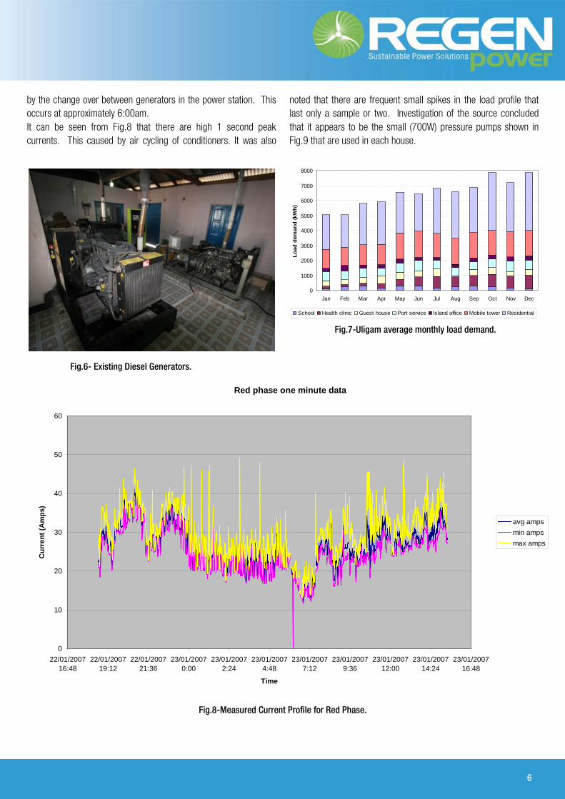
Fig .5- An aerial view of the Uligam island Electrical demand information was gathered from three sources. The community kept excellent records of the billing of the community loads. This data was available by month and was separated into commercial, government and residential users. Interviewing the community managers also provided information regarding seasonal and celebration effects on the community load. School holidays also affected the energy demand. These can be seen in the monthly records (Fig.7). The load profile for Uligam was determined by monitoring the system for a period of one day. From discussion with the power station operator, information regarding when the minimum loads occurred and when the maximum loads occurred was also obtained. It is worth noting that the growth of the load is about 4% per month over the year giving a total of about 50% per annum. The load current in one of the phases was measured during the site visit and shown in Fig.8. As seen in Fig.6 the moment of zero load is caused
0
1
2
3
4
5
6
7
8
9
Jan Feb Mar Apr May Jun Jul Aug Sep Oct Nov Dec
Win
d sp
eed
(m/s
)
0
1
2
3
4
5
6
7
Jan Feb Mar Apr May Jun Jul Aug Sep Oct Nov Dec
Sola
r irr
adia
nce
(kW
h/m
2)
6
by the change over between generators in the power station. This occurs at approximately 6:00am. It can be seen from Fig.8 that there are high 1 second peak currents. This caused by air cycling of conditioners. It was also
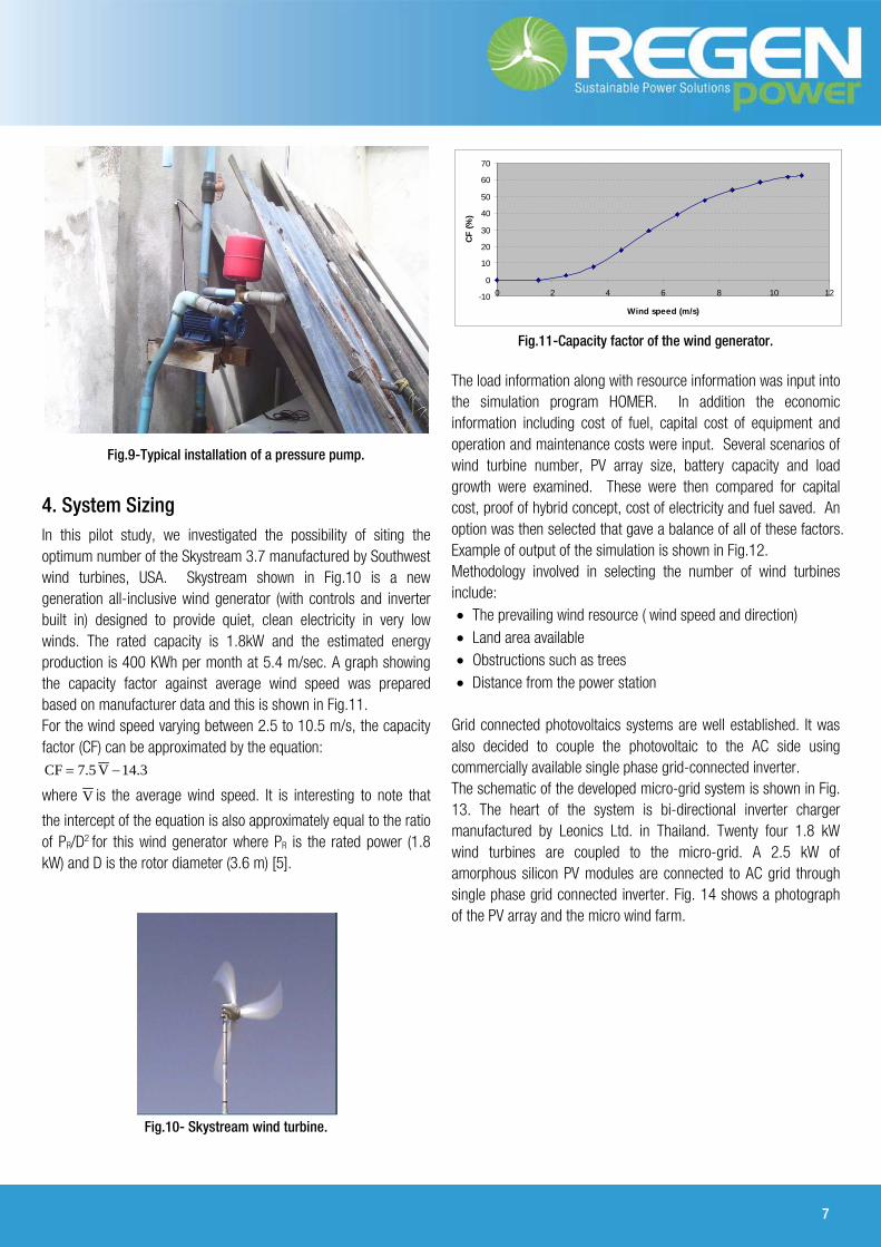
noted that there are frequent small spikes in the load profile that last only a sample or two. Investigation of the source concluded that it appears to be the small (700W) pressure pumps shown in Fig.9 that are used in each house.
Fig.7-Uligam average monthly load demand.
Fig.6- Existing Diesel Generators.
Fig.8-Measured Current Profile for Red Phase.
Red phase one minute data
0
10
20
30
40
50
60
22/01/200716:48
22/01/200719:12
22/01/200721:36
23/01/20070:00
23/01/20072:24
23/01/20074:48
23/01/20077:12
23/01/20079:36
23/01/200712:00
23/01/200714:24
23/01/200716:48
Time
Cur
rent
(Am
ps)
avg ampsmin ampsmax amps
0
1000
2000
3000
4000
5000
6000
7000
8000
Jan Feb Mar Apr May Jun Jul Aug Sep Oct Nov DecLo
ad d
eman
d (k
Wh)
School Health clinic Guest house Port service Island office Mobile tower Residential
7
Fig.9-Typical installation of a pressure pump.
4. System Sizing In this pilot study, we investigated the possibility of siting the optimum number of the Skystream 3.7 manufactured by Southwest wind turbines, USA. Skystream shown in Fig.10 is a new generation all-inclusive wind generator (with controls and inverter built in) designed to provide quiet, clean electricity in very low winds. The rated capacity is 1.8kW and the estimated energy production is 400 KWh per month at 5.4 m/sec. A graph showing the capacity factor against average wind speed was prepared based on manufacturer data and this is shown in Fig.11. For the wind speed varying between 2.5 to 10.5 m/s, the capacity factor (CF) can be approximated by the equation:
3.14V5.7CF −=
where V is the average wind speed. It is interesting to note that
the intercept of the equation is also approximately equal to the ratio of PR/D2 for this wind generator where PR is the rated power (1.8 kW) and D is the rotor diameter (3.6 m) [5].
Fig.10- Skystream wind turbine.
Fig.11-Capacity factor of the wind generator.
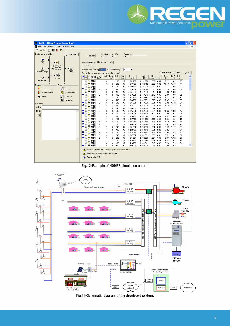
The load information along with resource information was input into the simulation program HOMER. In addition the economic information including cost of fuel, capital cost of equipment and operation and maintenance costs were input. Several scenarios of wind turbine number, PV array size, battery capacity and load growth were examined. These were then compared for capital cost, proof of hybrid concept, cost of electricity and fuel saved. An option was then selected that gave a balance of all of these factors. Example of output of the simulation is shown in Fig.12. Methodology involved in selecting the number of wind turbines include: • The prevailing wind resource ( wind speed and direction) • Land area available • Obstructions such as trees • Distance from the power station
Grid connected photovoltaics systems are well established. It was also decided to couple the photovoltaic to the AC side using commercially available single phase grid-connected inverter. The schematic of the developed micro-grid system is shown in Fig. 13. The heart of the system is bi-directional inverter charger manufactured by Leonics Ltd. in Thailand. Twenty four 1.8 kW wind turbines are coupled to the micro-grid. A 2.5 kW of amorphous silicon PV modules are connected to AC grid through single phase grid connected inverter. Fig. 14 shows a photograph of the PV array and the micro wind farm.
-10
0
10
20
30
40
50
60
70
0 2 4 6 8 10 12
Wind speed (m/s)
CF (%
)
8
Fig.12-Example of HOMER simulation output.
Fig.13-Schematic diagram of the developed system.

9
Fig.14 PV and part of wind turbine installation in Uligam.
Fig.15 Bidirectional Minigrid Inverter and the Distribution Control panels.
5. System Performance
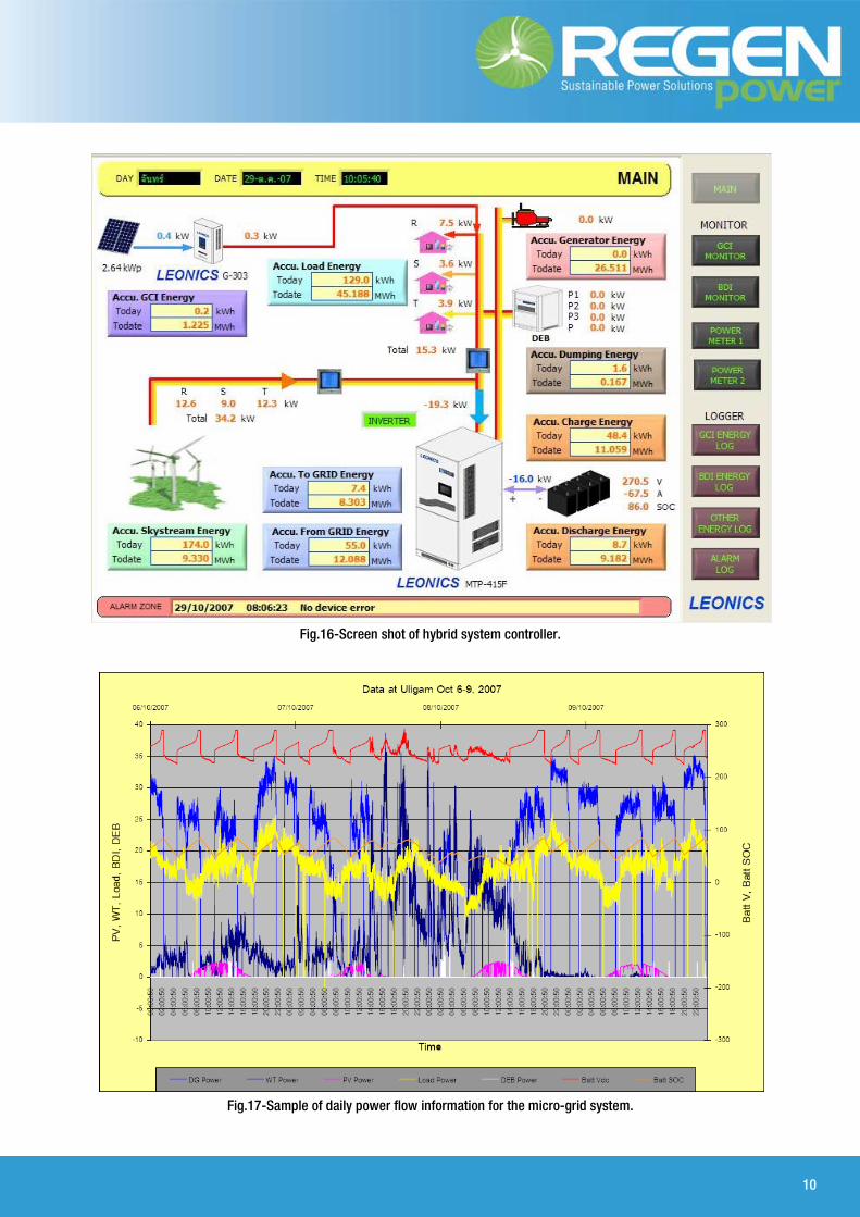
The hybrid system was installed and commissioned in August 2007. Preliminary performance data of this system was accessed through a remote monitoring system. Fig . 15 shows a photograph of the bidirectional mini grid inverter and the distribution control panels. Fig. 16 shows a real time captured information of the system on 29th October 2007. It can be seen that the combined of the output of the wind farm on the morning of the day is around 34.2 kW out of which 15.3 kW goes into the island load and 19.3 kW goes into the battery. The grid is provided by the bi-directional inverter with the diesel generator is not running. Fig. 17 shows recording of the power contribution from solar, wind and diesel generator for 4 days.
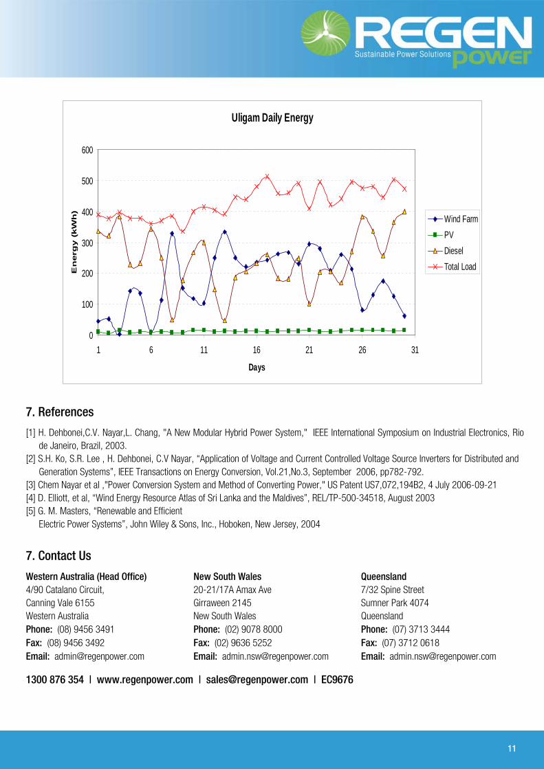
From the recorded data daily energy output from wind, PV and diesel was plotted in the first month of the installation (Fig. 18). The normalized capacity factor of wind farm and PV array were computed and shown in Fig. 19. The Microgrid system in Uligam was officially attended by the President of the Maldives on 7th January 2008..
6. Conclusion
Islands represent a big niche market for the application of renewable energy technologies and are very important when it comes to the promotion of renewable energy worldwide. The newly developed and installed system will provide very good opportunities to showcase high penetration of renewable energies using state of the art wind turbines, photovoltaic modules and advanced power electronics and control technology and the future possibilities of distributed generation in remote locations.
10
Fig.16-Screen shot of hybrid system controller.
Fig.17-Sample of daily power flow information for the micro-grid system.
11
7. References
[1] H. Dehbonei,C.V. Nayar,L. Chang, "A New Modular Hybrid Power System," IEEE International Symposium on Industrial Electronics, Rio de Janeiro, Brazil, 2003.
[2] S.H. Ko, S.R. Lee , H. Dehbonei, C.V Nayar, “Application of Voltage and Current Controlled Voltage Source Inverters for Distributed and Generation Systems”, IEEE Transactions on Energy Conversion, Vol.21,No.3, September 2006, pp782-792.
[3] Chem Nayar et al ,"Power Conversion System and Method of Converting Power," US Patent US7,072,194B2, 4 July 2006-09-21 [4] D. Elliott, et al, “Wind Energy Resource Atlas of Sri Lanka and the Maldives”, REL/TP-500-34518, August 2003 [5] G. M. Masters, “Renewable and Efficient Electric Power Systems”, John Wiley & Sons, Inc., Hoboken, New Jersey, 2004
7. Contact Us
Western Australia (Head Office) 4/90 Catalano Circuit, Canning Vale 6155 Western Australia Phone: (08) 9456 3491 Fax: (08) 9456 3492 Email: [email protected]
New South Wales 20-21/17A Amax Ave Girraween 2145 New South Wales Phone: (02) 9078 8000 Fax: (02) 9636 5252 Email: [email protected]
Queensland 7/32 Spine Street Sumner Park 4074 Queensland Phone: (07) 3713 3444 Fax: (07) 3712 0618 Email: [email protected]
1300 876 354 | www.regenpower.com | [email protected] | EC9676
Uligam Daily Energy
0
100
200
300
400
500
600
1 6 11 16 21 26 31
Days
En
erg
y (
kW
h)
Wind FarmPVDieselTotal Load


