00-02-0709 04-26-2010 Section 40
AFR-9R Air/Fuel Ratio Controller Installation and Operations Manual
Please read manual for hazard and safety advisement.
Read this entire manual and any other publications relevant to this project prior to installing, modifying or operating the equipment described herein. Follow safe practice standards. Observe all local, state and federal codes. Use this manual for safe, effective operation. Improper installation, operation or other use of this product could result in any combination of poor performance, equipment damage, human injury or possible death.
This manual is the sole property of FW Murphy/Compliance Controls. Copying, faxing, e-mailing, altering or in any way reproducing this manual in whole or in part is forbidden without the express written consent of FW Murphy/Compliance Controls.
FW Murphy and Compliance Controls reserves the right to change or alter any and all specifications at anytime without prior notification and without incurring any obligation to such changes. The information included in this publication is believed to be accurate at the time of publication; however, no responsibility is taken by FW Murphy/Compliance Controls unless expressly given.
04-26-10 i 00-02-0709 Section 40
Table of Contents SAFETY ..................................................................................................................................................................... 1
INTRODUCTION ....................................................................................................................................................... 3
PRODUCT OVERVIEW ............................................................................................................................................... 3 Single Set Point vs. Multi-set point Controllers ................................................................................................................... 3 Post Catalyst Oxygen Sensor ............................................................................................................................................. 4 The Choice of Fuel Valves Used with the AFR-9R ............................................................................................................. 4
PARTS AND SUPPLIES ........................................................................................................................................... 5
SYSTEMS PARTS CHECK LIST................................................................................................................................... 5 AFR-WD-R-9R-10-TK## (Single Bank - Pre Catalyst Control with Supplemental Fuel Valve) ........................................... 5 AFR-WD-R-9R-20-TK## (Dual Bank - Pre Catalyst Control with Supplemental Fuel Valve) .............................................. 5 AFR-WD-R-9R-10-FA## (Single Bank - Pre Catalyst Control with Full Authority Fuel Valve) ............................................ 6 AFR-WD-R-9R-20-FA## (Dual Bank - Pre Catalyst Control with Full Authority Fuel Valve) ............................................... 7 AFR-WD-R-9R-10-ICV75 (Single Bank – Pre Catalyst Control with In-Line Control Fuel Valve) ....................................... 8 AFR-WD-R-9R-20-ICV75 (Dual Bank - Pre Catalyst Control with In-Line Control Fuel Valve) ........................................... 8 Spare/ Loose Parts ............................................................................................................................................................. 9
PARTS IDENTIFICATION .......................................................................................................................................... 11
INSTALLATION ...................................................................................................................................................... 15
INSTALLATION CHECKLIST ...................................................................................................................................... 15 SAFEGUARDING ELECTRONICS ............................................................................................................................... 16 MATCHING THE KIT TO THE APPLICATION AND PARTS VERIFICATION ......................................................................... 17
Verify Package Contents .................................................................................................................................................. 17 GENERAL GUIDELINES FOR MOUNTING THE TK VALVE ............................................................................................ 18
TK Valve Mounting Foot Print ........................................................................................................................................... 20 General Guidelines for Mounting the Full Authority (FA) Valve......................................................................................... 21 General Guidelines for Mounting the In-Line Control (ICV) Valve..................................................................................... 24
HEGO SENSOR INSTALLATION GENERAL GUIDELINES ............................................................................................. 26 Pre-Catalyst HEGO Sensor .............................................................................................................................................. 26 Post Catalyst HEGO Sensor (optional) ............................................................................................................................. 26 HEGO Sensor Mounting ................................................................................................................................................... 28 HEGO Sensor Mounting Using HEGO Sensor Block ....................................................................................................... 30 MAP Sensor Installation ................................................................................................................................................... 33
MOUNTING OPTIONAL THERMOCOUPLES ................................................................................................................. 34 MOUNTING OPTIONAL MAGNETIC PICKUP ............................................................................................................... 34 ENCLOSURE MOUNTING AND CONDUIT ENTRIES ...................................................................................................... 35
Conduit Considerations .................................................................................................................................................... 35 WIRE TERMINATION ............................................................................................................................................... 36
AFR-9R Wiring Termination .............................................................................................................................................. 38
AFR-9R CONTROLLER OPERATION ................................................................................................................... 39
DISPLAY FEATURES ............................................................................................................................................... 39 AFR-9R MENUS .................................................................................................................................................... 41
Home Menu ...................................................................................................................................................................... 41 Help Menu ........................................................................................................................................................................ 41
NAVIGATION .......................................................................................................................................................... 42 Short-cut Buttons .............................................................................................................................................................. 42 Selecting and Editing Menu Options ................................................................................................................................. 42
INITIAL SETUP ....................................................................................................................................................... 43
CONTROLLER CONFIGURATION ............................................................................................................................... 43
INITIAL TUNING ..................................................................................................................................................... 44
FUEL PRESSURE CHECK ........................................................................................................................................ 45 INITIAL TUNING WHEN USING TK VALVE(S) ............................................................................................................. 48
04-26-10 ii 00-02-0709 Section 40
ADJUSTING THE CARBURETOR(S) AND FUEL PRESSURE FOR TK VALVE ................................................................... 48 INITIAL TUNING WHEN USING FULL AUTHORITY (FA) BUTTERFLY VALVE(S) .............................................................. 50 ADJUSTING THE CARBURETOR(S) AND FUEL PRESSURE FOR FULL AUTHORITY (FA) BUTTERFLY VALVE .................... 50
Determine FA Valve Cranking Position ............................................................................................................................. 52 INITIAL TUNING WHEN USING ICV VALVE(S) ............................................................................................................ 53 ADJUSTING THE CARBURETOR(S) AND FUEL PRESSURE FOR IN-LINE CONTROL (ICV) VALVE .................................... 53
TUNING FOR EMISSIONS ..................................................................................................................................... 55
TUNING FOR EMISSIONS - WITHOUT OPTIONAL POST CATALYST SENSOR ................................................................. 55 Determine Target Value .................................................................................................................................................... 55 Refine Target Values ........................................................................................................................................................ 56
TUNING FOR EMISSIONS WITH A POST CATALYST SENSOR. ...................................................................................... 57 Determine Target Value .................................................................................................................................................... 57 Refine Target Values ........................................................................................................................................................ 58
POST TUNING FOR EMISSIONS ................................................................................................................................ 59
TROUBLESHOOTING, MAINTENANCE AND REPLACEMENT .......................................................................... 60
PRODUCT SUPPORT .............................................................................................................................................. 60 VISUAL TROUBLESHOOTING AND METER CHECKING ................................................................................................ 61
Optional Type K Thermocouple – mV vs Temperature ..................................................................................................... 66 HEGO Sensor Milli-Volt vs. Estimated O2 Content ........................................................................................................... 67
TROUBLESHOOTING ACTION STEPS ........................................................................................................................ 68 TROUBLESHOOTING GUIDE .................................................................................................................................... 69 MAINTENANCE AND REPLACEMENT ......................................................................................................................... 73
Replacement Information .................................................................................................................................................. 73
SYSTEM SPECIFICATIONS ................................................................................................................................... 74
INSTALLATION DRAWINGS ................................................................................................................................. 76
AFR-WD-R-9R-10-TK## ⎯ SINGLE HIGH PRESSURE CARBURETOR .................................................................... 76 AFR-WD-R-9R-10-TK## ⎯ SINGLE LOW PRESSURE CARBURETOR ...................................................................... 77 AFR-WD-R-9R-20-TK## ⎯ DUAL HIGH PRESSURE CARBURETORS ...................................................................... 78 AFR-WD-R-9R-20-TK## ⎯ DUAL CARBURETORS / COMMON EXHAUST MANIFOLD ............................................... 79 AFR-WD-R-9R-10-TK## ⎯DUAL LOW PRESSURE CARBURETORS/SINGLE PRE CAT SENSOR ............................... 80 AFR-WD-R-9R-10-TK## ⎯SINGLE CARBURETOR / DUAL BANK ENGINE ................................................................ 81 AFR-WD-R-9R-10-FA## ⎯SINGLE HIGH PRESSURE CARBURETOR ...................................................................... 82 AFR-WD-R-9R-10-FA## ⎯SINGLE LOW PRESSURE CARBURETOR ....................................................................... 83 AFR-WD-R-9R-20-FA## ⎯DUAL HIGH PRESSURE CARBURETOR ......................................................................... 84 AFR-WD-R-9R-20-FA## ⎯DUAL CARBURETOR / COMMON EXHAUST MANIFOLD ................................................... 85 AFR-WD-R-9R-20-FA## ⎯DUAL HIGH PRESSURE CARBURETOR/SINGLE PRE CAT SENSOR ................................ 86 AFR-WD-R-9R-10-FA## ⎯SINGLE HIGH PRESSURE CARBURETOR / DUAL BANK ENGINE ..................................... 87 AFR-WD-R-9R-10-ICV-75 ⎯ SINGLE HIGH PRESSURE CARBURETOR ................................................................... 88 AFR-WD-R-9R -10- ICV-75 ⎯ SINGLE LOW PRESSURE CARBURETOR .................................................................. 89 AFR-WD-R-9R -20- ICV-75 ⎯ DUAL HIGH PRESSURE CARBURETOR .................................................................... 90 AFR-WD-R-9R-20- ICV-75 ⎯ DUAL CARBURETOR / COMMON EXHAUST MANIFOLD ............................................... 91 AFR-WD-R-9R-20- ICV-75 ⎯ DUAL LOW PRESSURE CARBURETOR/SINGLE PRE CAT SENSOR .............................. 92 AFR-WD-R-9R-10- ICV-75 ⎯ SINGLE HIGH PRESSURE CARBURETOR / DUAL BANK ENGINE .................................. 93
04-26-10 1 00-02-0709 Section 40
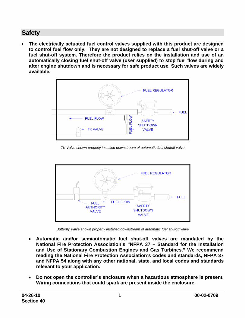
Safety • The electrically actuated fuel control valves supplied with this product are designed
to control fuel flow only. They are not designed to replace a fuel shut-off valve or a fuel shut-off system. Therefore the product relies on the installation and use of an automatically closing fuel shut-off valve (user supplied) to stop fuel flow during and after engine shutdown and is necessary for safe product use. Such valves are widely available.
FUEL REGULATOR
SHUTDOWNSAFETY
VALVE
FUEL FLOW
FUE
L FL
OW
FUEL
TK VALVE
TK Valve shown properly installed downstream of automatic fuel shutoff valve
FUEL REGULATOR
SHUTDOWNSAFETY
VALVE
FUEL FLOWFULLAUTHORITY
VALVE
FUEL
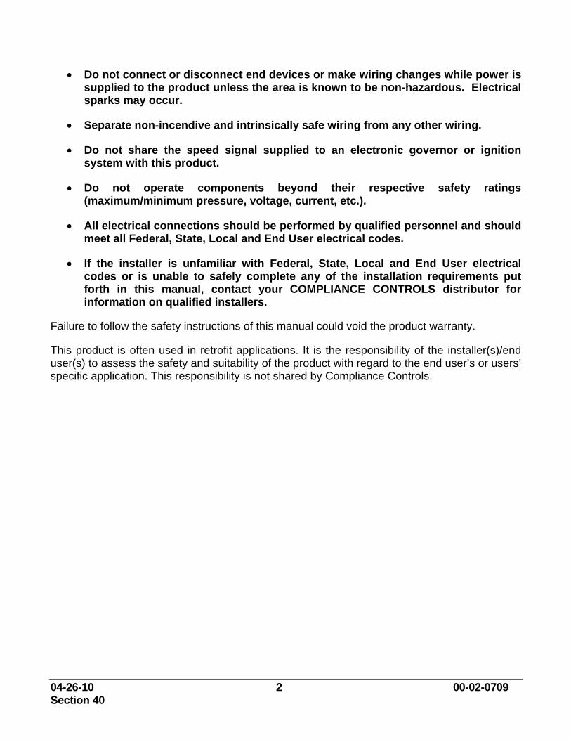
Butterfly Valve shown properly installed downstream of automatic fuel shutoff valve
• Automatic and/or semiautomatic fuel shut-off valves are mandated by the National Fire Protection Association’s “NFPA 37 – Standard for the Installation and Use of Stationary Combustion Engines and Gas Turbines.” We recommend reading the National Fire Protection Association’s codes and standards, NFPA 37 and NFPA 54 along with any other national, state, and local codes and standards relevant to your application.
• Do not open the controller’s enclosure when a hazardous atmosphere is present. Wiring connections that could spark are present inside the enclosure.
04-26-10 2 00-02-0709 Section 40
• Do not connect or disconnect end devices or make wiring changes while power is supplied to the product unless the area is known to be non-hazardous. Electrical sparks may occur.
• Separate non-incendive and intrinsically safe wiring from any other wiring.
• Do not share the speed signal supplied to an electronic governor or ignition system with this product.
• Do not operate components beyond their respective safety ratings (maximum/minimum pressure, voltage, current, etc.).
• All electrical connections should be performed by qualified personnel and should meet all Federal, State, Local and End User electrical codes.
• If the installer is unfamiliar with Federal, State, Local and End User electrical codes or is unable to safely complete any of the installation requirements put forth in this manual, contact your COMPLIANCE CONTROLS distributor for information on qualified installers.
Failure to follow the safety instructions of this manual could void the product warranty.
This product is often used in retrofit applications. It is the responsibility of the installer(s)/end user(s) to assess the safety and suitability of the product with regard to the end user’s or users’ specific application. This responsibility is not shared by Compliance Controls.
04-26-10 3 00-02-0709 Section 40
Introduction The AFR-9R is often sold as a retrofit product. As with all retrofit products, it is not possible for the manual to address every “bend and turn” users may encounter with their particular application. Consequently, it is important for both installers and users alike to understand the underlying concepts of the AFR-9R to increase their odds of success when circumstances deviate from those anticipated herein. Keep in mind your distributor’s purpose is to help in this regard.
Product Overview It is a common misconception that air/fuel ratio controllers (AFRC's) reduce emissions. Only catalysts reduce emissions. However, for every 3-way catalyst, there is a specific air/fuel ratio at which the catalyst performs best. This "sweet spot" is found by adjusting the fuel delivery to the carburetor. Maintaining this "sweet spot" is the job of an air/fuel ratio controller.
The AFR-9R controller uses a heated oxygen sensor mounted in the engine’s exhaust (upstream of the catalyst) to detect drift in the engine’s air/fuel ratio over time. As an engine drifts "Lean" there is less fuel to combine with oxygen during combustion leaving more “leftover” oxygen passing into the exhaust. An engine drifting "Rich" is the opposite. More fuel requires more oxygen to burn, leaving less pure oxygen passing into the exhaust.
To determine the oxygen sensor value corresponding to your catalyst’s "sweet spot," you must use an Exhaust Gas Analyzer. You will then enter this sensor value into the controller as a "target." From that point on, the controller will:
1. Measure the oxygen sensor's value.
2. Compare it with the target to determine if the engine is drifting rich or lean and calculate how much.
3. Decide what action to take and how severe (controlled by the GAIN) it should be.
4. Act using a valve to change the fuel flow to the engine so as to bring the air/fuel ratio back to your target.
These steps are repeated infinitely to maintain control.
Single Set Point vs. Multi-set point Controllers
The AFR-9R is a multi-set point controller which adds a degree of complexity to its setup and operation. To understand the AFR-9R, it is helpful to first consider a single set point controller. With a single set point controller, the same air/fuel set point is used regardless of engine load. This style of controller is sufficient for many applications. However, in some applications the optimum air/fuel value for one operating load may not be the optimum value for a different load.
04-26-10 4 00-02-0709 Section 40
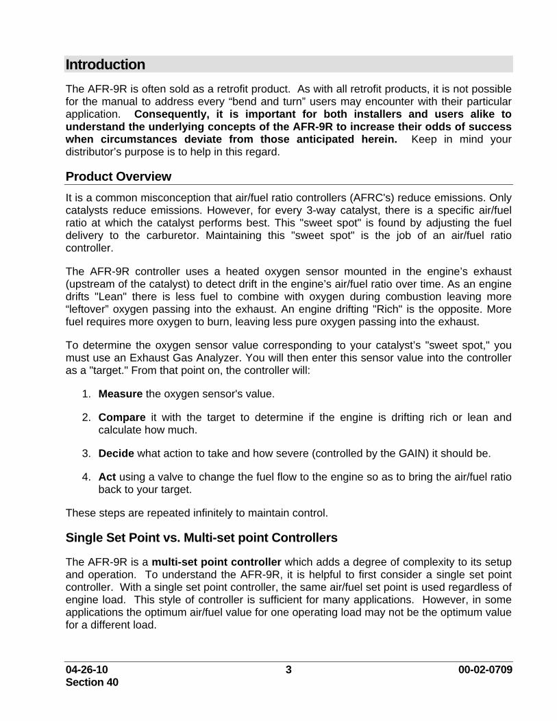
In areas where emission limits are particularly tight, the AFR-9R provides a means for entering multiple air/fuel targets to be matched with specific engine loads. The AFR-9R does this by providing the user with a two dimensional table consisting of three RPM points and three manifold pressure points creating nine possible air/fuel targets.
During operation, the controller determines engine load by monitoring both manifold pressure and engine speed. Using these, the AFR-9R interpolates an air/fuel set point from among the nearest corresponding points of the table.
Post Catalyst Oxygen Sensor
As an additional option, the AFR-9R offers the ability to run a post catalyst oxygen sensor. In many cases, a post catalyst oxygen sensor can enable the AFR-9R to compensate for slight changes in the system over time.
Post catalyst control may be thought of as a separate controller unto itself. The post catalyst control loop compares the reading from the post catalyst sensor with the user set target (interpolated from another 9 point table not to be confused with the pre-catalyst table) and biases the pre catalyst target rich or lean depending upon the error.
In short, the post catalyst control loop adjusts the pre catalyst targets in order to richen or lean the engine. The point to remember is that its ability to adjust the pre catalyst target is limited to + or - .010. Therefore during setup and tuning, richening or leaning the air/fuel ratio of the engine by solely adjusting the post catalyst set points can only have a limited effect. In practice BOTH pre and post catalyst tables must be adjusted.
One may know if it is time to adjust the pre catalyst target by looking at the Pre Catalyst Offset value located on the Main View page. If it is at .010 or -.010, then the post catalyst loop has done all it can and the pre catalyst target must be adjusted in the desired direction to cause further change.
Fuel Valves Used with the AFR-9R
The AFR-9R is a multi set point controller that may be used with three different fuel control strategies: a proportional solenoid valve (the TK Valve) mounted in an auxiliary fuel line, a full authority (FA) butterfly valve mounted in the main fuel line, or the ICV-75 valve mounted in the main fuel line. Due to the differences among these fuel control strategies, for convenience much of this manual is divided to address these separately. Those sections not involving the reader’s valve selection may be skipped.
04-26-10 5 00-02-0709 Section 40
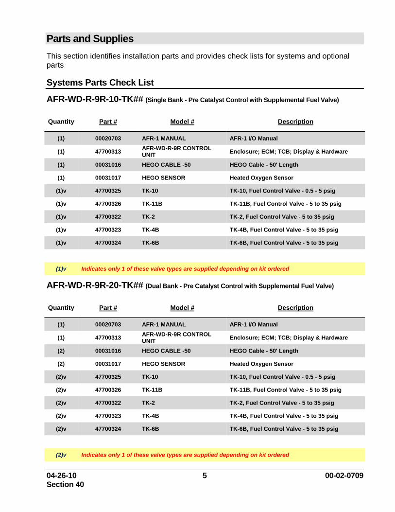
Parts and Supplies This section identifies installation parts and provides check lists for systems and optional parts
Systems Parts Check List
AFR-WD-R-9R-10-TK## (Single Bank - Pre Catalyst Control with Supplemental Fuel Valve)
Quantity Part # Model # Description
(1) 00020703 AFR-1 MANUAL AFR-1 I/O Manual
(1) 47700313 AFR-WD-R-9R CONTROL UNIT Enclosure; ECM; TCB; Display & Hardware
(1) 00031016 HEGO CABLE -50 HEGO Cable - 50' Length
(1) 00031017 HEGO SENSOR Heated Oxygen Sensor
(1)v 47700325 TK-10 TK-10, Fuel Control Valve - 0.5 - 5 psig
(1)v 47700326 TK-11B TK-11B, Fuel Control Valve - 5 to 35 psig
(1)v 47700322 TK-2 TK-2, Fuel Control Valve - 5 to 35 psig
(1)v 47700323 TK-4B TK-4B, Fuel Control Valve - 5 to 35 psig
(1)v 47700324 TK-6B TK-6B, Fuel Control Valve - 5 to 35 psig
(1)v Indicates only 1 of these valve types are supplied depending on kit ordered
AFR-WD-R-9R-20-TK## (Dual Bank - Pre Catalyst Control with Supplemental Fuel Valve)
Quantity Part # Model # Description
(1) 00020703 AFR-1 MANUAL AFR-1 I/O Manual
(1) 47700313 AFR-WD-R-9R CONTROL UNIT Enclosure; ECM; TCB; Display & Hardware
(2) 00031016 HEGO CABLE -50 HEGO Cable - 50' Length
(2) 00031017 HEGO SENSOR Heated Oxygen Sensor
(2)v 47700325 TK-10 TK-10, Fuel Control Valve - 0.5 - 5 psig
(2)v 47700326 TK-11B TK-11B, Fuel Control Valve - 5 to 35 psig
(2)v 47700322 TK-2 TK-2, Fuel Control Valve - 5 to 35 psig
(2)v 47700323 TK-4B TK-4B, Fuel Control Valve - 5 to 35 psig
(2)v 47700324 TK-6B TK-6B, Fuel Control Valve - 5 to 35 psig
(2)v Indicates only 1 of these valve types are supplied depending on kit ordered
04-26-10 6 00-02-0709 Section 40
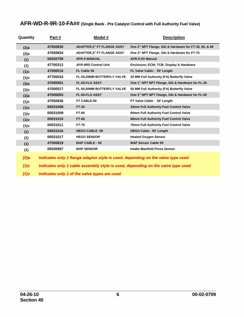
AFR-WD-R-9R-10-FA## (Single Bank - Pre Catalyst Control with Full Authority Fuel Valve)
Quantity Part # Model # Description
(2)a 47050835 ADAPTER,2" FT FLANGE ASSY One 2" NPT Flange, Gkt & Hardware for FT-33, 60, & 68
(2)a 47050834 ADAPTER,3" FT FLANGE ASSY One 3" NPT Flange, Gkt & Hardware for FT-75
(1) 00020709 AFR-9 MANUAL AFR-9 I/O Manual
(1) 47700312 AFR-9RD Control Unit Enclosure; ECM; TCB; Display & Hardware
(1)c 47000016 FL Cable 50 FL Valve Cable - 50' Length
(1)v 47700033 FL-25,25MM BUTTERFLY VALVE 25 MM Full Authority (FA) Butterfly Valve
(2)a 47000001 FL-25-FLG ASSY One 1" NPT NPT Flange, Gkt & Hardware for FL-25
(1)v 47000017 FL-50,50MM BUTTERFLY VALVE 50 MM Full Authority (FA) Butterfly Valve
(2)a 47000003 FL-50-FLG ASSY One 2" NPT NPT Flange, Gkt & Hardware for FL-50
(1)c 47050836 FT CABLE-50 FT Valve Cable - 50' Length
(1)v 00031008 FT-33 33mm Full Authority Fuel Control Valve
(1)v 00031009 FT-60 60mm Full Authority Fuel Control Valve
(1)v 00031010 FT-68 68mm Full Authority Fuel Control Valve
(1)v 00031011 FT-75 75mm Full Authority Fuel Control Valve
(1) 00031016 HEGO CABLE -50 HEGO Cable - 50' Length
(1) 00031017 HEGO SENSOR Heated Oxygen Sensor
(1) 47050819 MAP CABLE - 50 MAP Sensor Cable 50'
(1) 00030997 MAP SENSOR Intake Manifold Press Sensor
(2)a Indicates only 1 flange adaptor style is used, depending on the valve type used
(1)c Indicates only 1 cable assembly style is used, depending on the valve type used
(1)v Indicates only 1 of the valve types are used
04-26-10 7 00-02-0709 Section 40
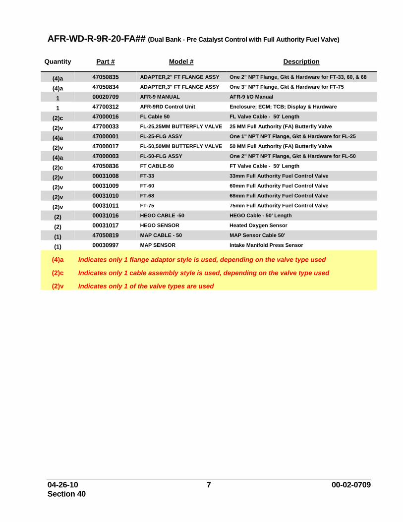
AFR-WD-R-9R-20-FA## (Dual Bank - Pre Catalyst Control with Full Authority Fuel Valve)
Quantity Part # Model # Description
(4)a 47050835 ADAPTER,2" FT FLANGE ASSY One 2" NPT Flange, Gkt & Hardware for FT-33, 60, & 68
(4)a 47050834 ADAPTER,3" FT FLANGE ASSY One 3" NPT Flange, Gkt & Hardware for FT-75
1 00020709 AFR-9 MANUAL AFR-9 I/O Manual
1 47700312 AFR-9RD Control Unit Enclosure; ECM; TCB; Display & Hardware
(2)c 47000016 FL Cable 50 FL Valve Cable - 50' Length
(2)v 47700033 FL-25,25MM BUTTERFLY VALVE 25 MM Full Authority (FA) Butterfly Valve
(4)a 47000001 FL-25-FLG ASSY One 1" NPT NPT Flange, Gkt & Hardware for FL-25
(2)v 47000017 FL-50,50MM BUTTERFLY VALVE 50 MM Full Authority (FA) Butterfly Valve
(4)a 47000003 FL-50-FLG ASSY One 2" NPT NPT Flange, Gkt & Hardware for FL-50
(2)c 47050836 FT CABLE-50 FT Valve Cable - 50' Length
(2)v 00031008 FT-33 33mm Full Authority Fuel Control Valve
(2)v 00031009 FT-60 60mm Full Authority Fuel Control Valve
(2)v 00031010 FT-68 68mm Full Authority Fuel Control Valve
(2)v 00031011 FT-75 75mm Full Authority Fuel Control Valve
(2) 00031016 HEGO CABLE -50 HEGO Cable - 50' Length
(2) 00031017 HEGO SENSOR Heated Oxygen Sensor
(1) 47050819 MAP CABLE - 50 MAP Sensor Cable 50'
(1) 00030997 MAP SENSOR Intake Manifold Press Sensor
(4)a Indicates only 1 flange adaptor style is used, depending on the valve type used
(2)c Indicates only 1 cable assembly style is used, depending on the valve type used
(2)v Indicates only 1 of the valve types are used
04-26-10 8 00-02-0709 Section 40
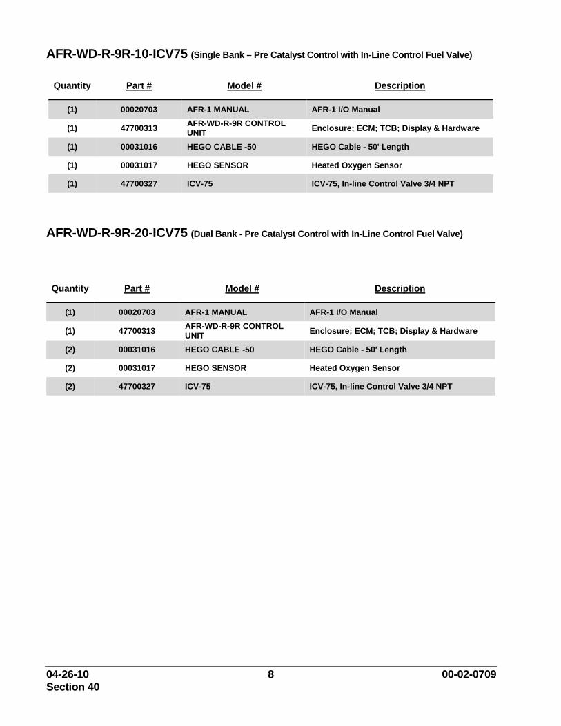
AFR-WD-R-9R-10-ICV75 (Single Bank – Pre Catalyst Control with In-Line Control Fuel Valve)
Quantity Part # Model # Description
(1) 00020703 AFR-1 MANUAL AFR-1 I/O Manual
(1) 47700313 AFR-WD-R-9R CONTROL UNIT Enclosure; ECM; TCB; Display & Hardware
(1) 00031016 HEGO CABLE -50 HEGO Cable - 50' Length
(1) 00031017 HEGO SENSOR Heated Oxygen Sensor
(1) 47700327 ICV-75 ICV-75, In-line Control Valve 3/4 NPT
AFR-WD-R-9R-20-ICV75 (Dual Bank - Pre Catalyst Control with In-Line Control Fuel Valve)
Quantity Part # Model # Description
(1) 00020703 AFR-1 MANUAL AFR-1 I/O Manual
(1) 47700313 AFR-WD-R-9R CONTROL UNIT Enclosure; ECM; TCB; Display & Hardware
(2) 00031016 HEGO CABLE -50 HEGO Cable - 50' Length
(2) 00031017 HEGO SENSOR Heated Oxygen Sensor
(2) 47700327 ICV-75 ICV-75, In-line Control Valve 3/4 NPT
04-26-10 9 00-02-0709 Section 40
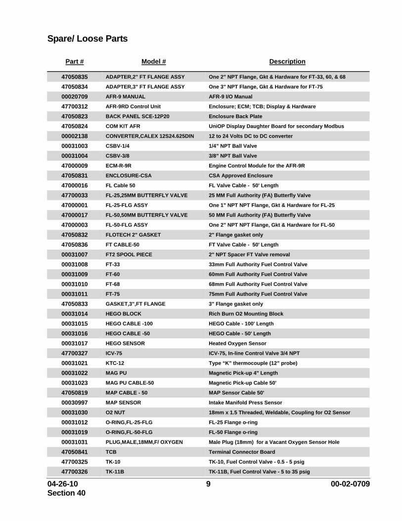
Spare/ Loose Parts
Part # Model # Description
47050835 ADAPTER,2" FT FLANGE ASSY One 2" NPT Flange, Gkt & Hardware for FT-33, 60, & 68
47050834 ADAPTER,3" FT FLANGE ASSY One 3" NPT Flange, Gkt & Hardware for FT-75
00020709 AFR-9 MANUAL AFR-9 I/O Manual
47700312 AFR-9RD Control Unit Enclosure; ECM; TCB; Display & Hardware
47050823 BACK PANEL SCE-12P20 Enclosure Back Plate
47050824 COM KIT AFR UniOP Display Daughter Board for secondary Modbus
00002138 CONVERTER,CALEX 12S24.625DIN 12 to 24 Volts DC to DC converter
00031003 CSBV-1/4 1/4” NPT Ball Valve
00031004 CSBV-3/8 3/8” NPT Ball Valve
47000009 ECM-R-9R Engine Control Module for the AFR-9R
47050831 ENCLOSURE-CSA CSA Approved Enclosure
47000016 FL Cable 50 FL Valve Cable - 50' Length
47700033 FL-25,25MM BUTTERFLY VALVE 25 MM Full Authority (FA) Butterfly Valve
47000001 FL-25-FLG ASSY One 1" NPT NPT Flange, Gkt & Hardware for FL-25
47000017 FL-50,50MM BUTTERFLY VALVE 50 MM Full Authority (FA) Butterfly Valve
47000003 FL-50-FLG ASSY One 2" NPT NPT Flange, Gkt & Hardware for FL-50
47050832 FLOTECH 2" GASKET 2" Flange gasket only
47050836 FT CABLE-50 FT Valve Cable - 50' Length
00031007 FT2 SPOOL PIECE 2" NPT Spacer FT Valve removal
00031008 FT-33 33mm Full Authority Fuel Control Valve
00031009 FT-60 60mm Full Authority Fuel Control Valve
00031010 FT-68 68mm Full Authority Fuel Control Valve
00031011 FT-75 75mm Full Authority Fuel Control Valve
47050833 GASKET,3",FT FLANGE 3" Flange gasket only
00031014 HEGO BLOCK Rich Burn O2 Mounting Block
00031015 HEGO CABLE -100 HEGO Cable - 100' Length
00031016 HEGO CABLE -50 HEGO Cable - 50' Length
00031017 HEGO SENSOR Heated Oxygen Sensor
47700327 ICV-75 ICV-75, In-line Control Valve 3/4 NPT
00031021 KTC-12 Type “K” thermocouple (12” probe)
00031022 MAG PU Magnetic Pick-up 4" Length
00031023 MAG PU CABLE-50 Magnetic Pick-up Cable 50'
47050819 MAP CABLE - 50 MAP Sensor Cable 50'
00030997 MAP SENSOR Intake Manifold Press Sensor
00031030 O2 NUT 18mm x 1.5 Threaded, Weldable, Coupling for O2 Sensor
00031012 O-RING,FL-25-FLG FL-25 Flange o-ring
00031019 O-RING,FL-50-FLG FL-50 Flange o-ring
00031031 PLUG,MALE,18MM,F/ OXYGEN Male Plug (18mm) for a Vacant Oxygen Sensor Hole
47050841 TCB Terminal Connector Board
47700325 TK-10 TK-10, Fuel Control Valve - 0.5 - 5 psig
47700326 TK-11B TK-11B, Fuel Control Valve - 5 to 35 psig
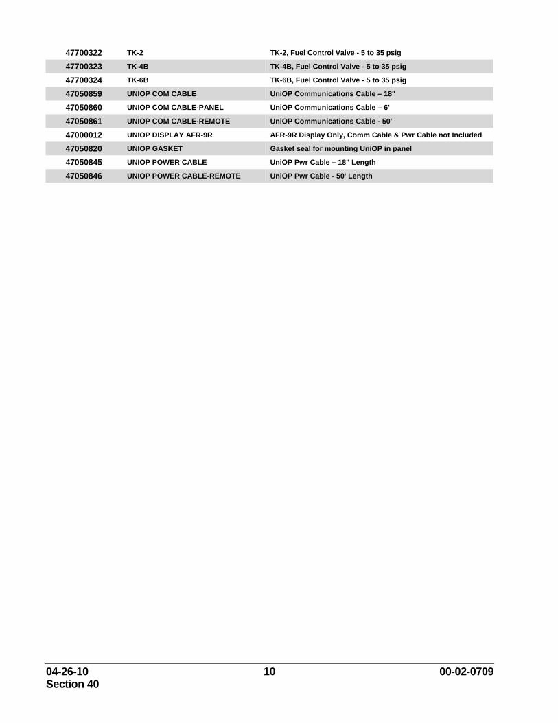
04-26-10 10 00-02-0709 Section 40
47700322 TK-2 TK-2, Fuel Control Valve - 5 to 35 psig
47700323 TK-4B TK-4B, Fuel Control Valve - 5 to 35 psig
47700324 TK-6B TK-6B, Fuel Control Valve - 5 to 35 psig
47050859 UNIOP COM CABLE UniOP Communications Cable – 18"
47050860 UNIOP COM CABLE-PANEL UniOP Communications Cable – 6'
47050861 UNIOP COM CABLE-REMOTE UniOP Communications Cable - 50'
47000012 UNIOP DISPLAY AFR-9R AFR-9R Display Only, Comm Cable & Pwr Cable not Included
47050820 UNIOP GASKET Gasket seal for mounting UniOP in panel
47050845 UNIOP POWER CABLE UniOP Pwr Cable – 18" Length
47050846 UNIOP POWER CABLE-REMOTE UniOP Pwr Cable - 50' Length
04-26-10 11 00-02-0709 Section 40
Parts Identification Please remember your specific kit may not include all of these parts. Refer to the Installation section of this manual for a parts listing of each kit.
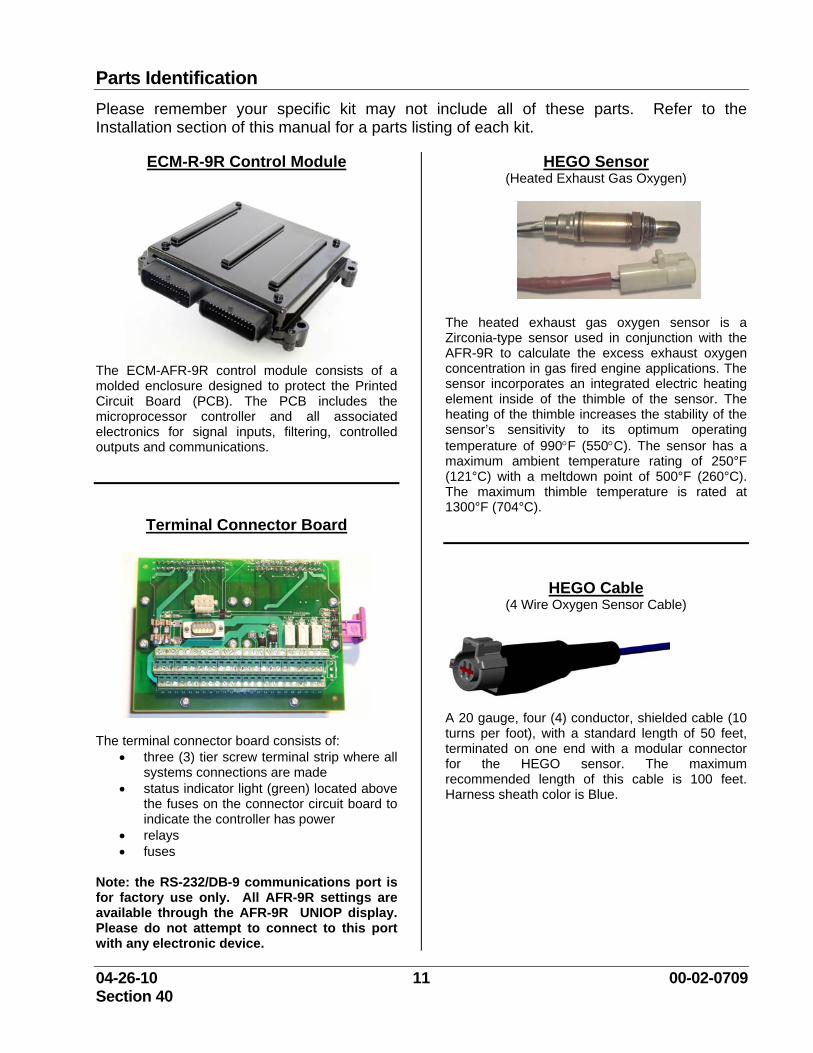
ECM-R-9R Control Module
The ECM-AFR-9R control module consists of a molded enclosure designed to protect the Printed Circuit Board (PCB). The PCB includes the microprocessor controller and all associated electronics for signal inputs, filtering, controlled outputs and communications.
Terminal Connector Board
The terminal connector board consists of: • three (3) tier screw terminal strip where all
systems connections are made • status indicator light (green) located above
the fuses on the connector circuit board to indicate the controller has power
• relays • fuses
Note: the RS-232/DB-9 communications port is for factory use only. All AFR-9R settings are available through the AFR-9R UNIOP display. Please do not attempt to connect to this port with any electronic device.
HEGO Sensor (Heated Exhaust Gas Oxygen)
The heated exhaust gas oxygen sensor is a Zirconia-type sensor used in conjunction with the AFR-9R to calculate the excess exhaust oxygen concentration in gas fired engine applications. The sensor incorporates an integrated electric heating element inside of the thimble of the sensor. The heating of the thimble increases the stability of the sensor’s sensitivity to its optimum operating temperature of 990°F (550°C). The sensor has a maximum ambient temperature rating of 250°F (121°C) with a meltdown point of 500°F (260°C). The maximum thimble temperature is rated at 1300°F (704°C).
HEGO Cable
(4 Wire Oxygen Sensor Cable)
A 20 gauge, four (4) conductor, shielded cable (10 turns per foot), with a standard length of 50 feet, terminated on one end with a modular connector for the HEGO sensor. The maximum recommended length of this cable is 100 feet. Harness sheath color is Blue.
04-26-10 12 00-02-0709 Section 40
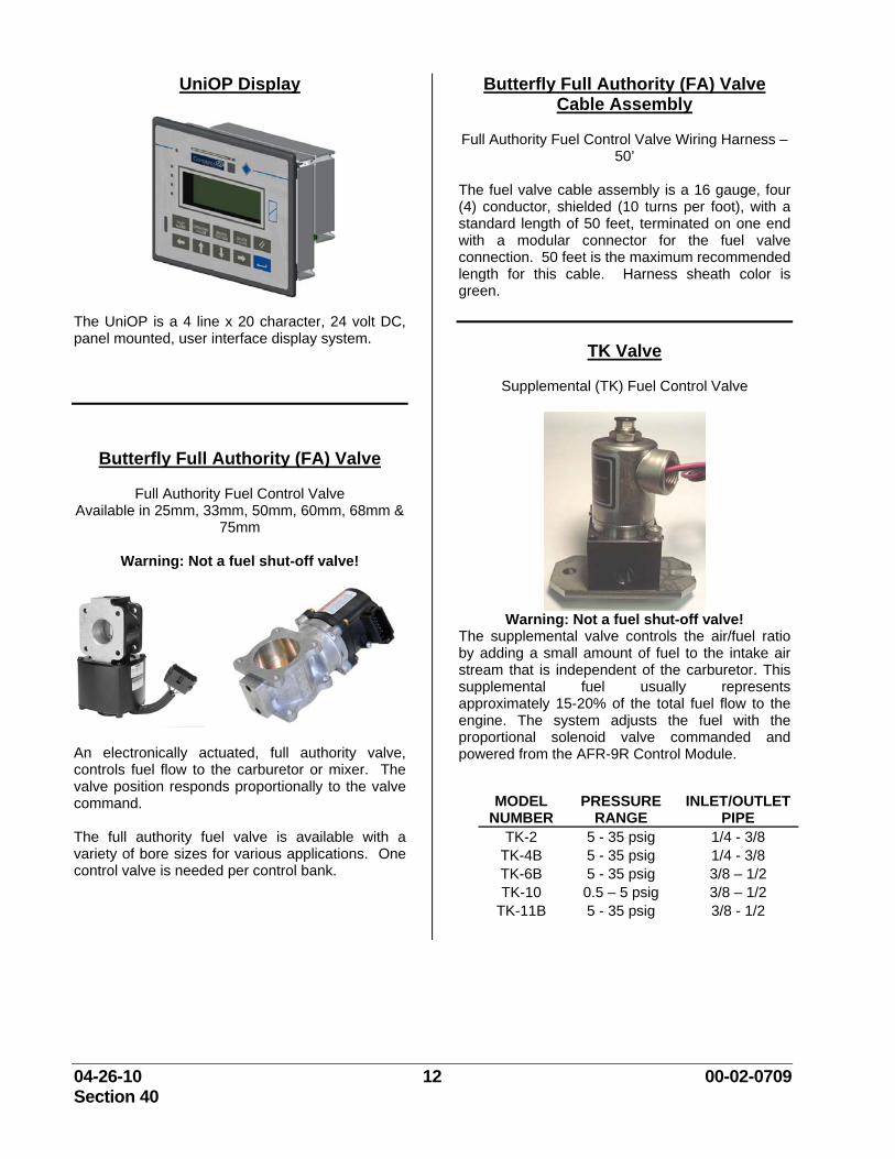
UniOP Display
The UniOP is a 4 line x 20 character, 24 volt DC, panel mounted, user interface display system.
Butterfly Full Authority (FA) Valve
Full Authority Fuel Control Valve Available in 25mm, 33mm, 50mm, 60mm, 68mm &
75mm
Warning: Not a fuel shut-off valve!
An electronically actuated, full authority valve, controls fuel flow to the carburetor or mixer. The valve position responds proportionally to the valve command. The full authority fuel valve is available with a variety of bore sizes for various applications. One control valve is needed per control bank.
Butterfly Full Authority (FA) Valve Cable Assembly
Full Authority Fuel Control Valve Wiring Harness –
50’
The fuel valve cable assembly is a 16 gauge, four (4) conductor, shielded (10 turns per foot), with a standard length of 50 feet, terminated on one end with a modular connector for the fuel valve connection. 50 feet is the maximum recommended length for this cable. Harness sheath color is green.
TK Valve
Supplemental (TK) Fuel Control Valve
Warning: Not a fuel shut-off valve!
The supplemental valve controls the air/fuel ratio by adding a small amount of fuel to the intake air stream that is independent of the carburetor. This supplemental fuel usually represents approximately 15-20% of the total fuel flow to the engine. The system adjusts the fuel with the proportional solenoid valve commanded and powered from the AFR-9R Control Module.
MODEL NUMBER
PRESSURE RANGE
INLET/OUTLET PIPE
TK-2 5 - 35 psig 1/4 - 3/8 TK-4B 5 - 35 psig 1/4 - 3/8 TK-6B 5 - 35 psig 3/8 – 1/2 TK-10 0.5 – 5 psig 3/8 – 1/2
TK-11B 5 - 35 psig 3/8 - 1/2
04-26-10 13 00-02-0709 Section 40
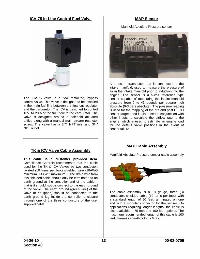
ICV-75 In-Line Control Fuel Valve
The ICV-75 valve is a flow restricted, bypass control valve. This valve is designed to be installed in the main fuel line between the final cut regulator and the carburetor. The ICV is designed to control 10% to 20% of the fuel flow to the carburetor. The valve is designed around a solenoid actuated orifice along with a manual main stream restrictor screw. The valve has a 3/4” NPT inlet and 3/4” NPT outlet.
TK & ICV Valve Cable Assembly This cable is a customer provided item. Compliance Controls recommends that the cable used for the TK & ICV Valves be two conductor, twisted (10 turns per foot) shielded wire (18AWG minimum, 14AWG maximum). The drain wire from this shielded cable should only be terminated to an earth ground at the controller end of the cable – that is it should not be connect to the earth ground of the valve. The earth ground (green wire) of the valve (if equipped) should be connected to the earth ground lug inside the controller enclosure through one of the three conductors of the user supplied cable.
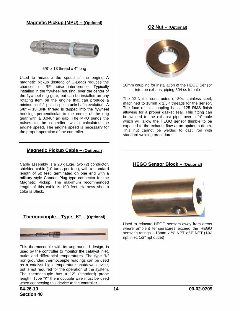
MAP Sensor
Manifold Absolute Pressure sensor
A pressure transducer that is connected to the intake manifold, used to measure the pressure of air in the intake manifold prior to induction into the engine. The sensor is a 5-volt reference type sensor capable of measuring the intake manifold pressure from 0 to 43 pounds per square inch absolute (0-3 bars absolute). The pressure reading is used for the mapping of the pre and post HEGO sensor targets and is also used in conjunction with other inputs to calculate the airflow rate to the engine, which is used to estimate an engine load for the default valve positions in the event of sensor failure.
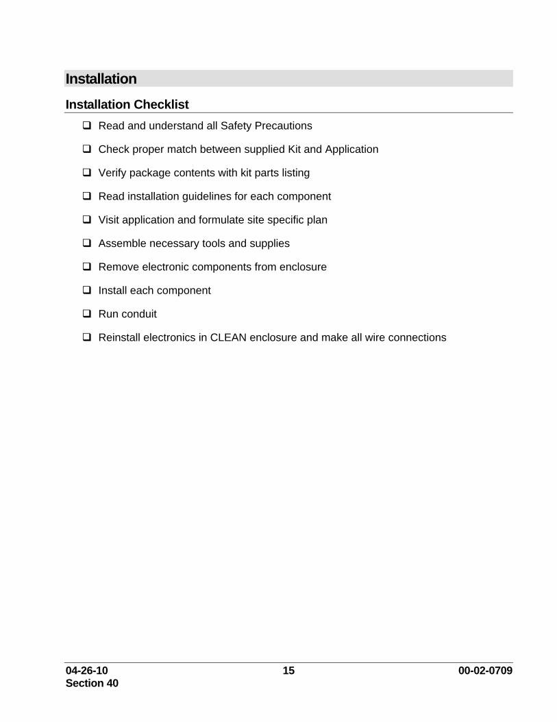
MAP Cable Assembly
Manifold Absolute Pressure sensor cable assembly
The cable assembly is a 18 gauge, three (3) conductor, shielded cable (10 turns per foot), with a standard length of 50 feet, terminated on one end with a modular connector for the sensor. On applications requiring longer lengths, the cable is also available in 75 feet and 100 feet options. The maximum recommended length of this cable is 100 feet. Harness sheath color is Gray.
04-26-10 14 00-02-0709 Section 40
Magnetic Pickup (MPU) – (Optional)
5/8” x 18 thread x 4” long
Used to measure the speed of the engine A magnetic pickup (instead of G-Lead) reduces the chances of RF noise interference. Typically installed in the flywheel housing, over the center of the flywheel ring gear, but can be installed on any rotating item on the engine that can produce a minimum of 2 pulses per crankshaft revolution. A 5/8” – 18 UNF thread is tapped into the flywheel housing, perpendicular to the center of the ring gear with a 0.040” air gap. The MPU sends the pulses to the controller, which calculates the engine speed. The engine speed is necessary for the proper operation of the controller.
Magnetic Pickup Cable – (Optional)
Cable assembly is a 20 gauge, two (2) conductor, shielded cable (10 turns per foot), with a standard length of 50 feet, terminated on one end with a military style Cannon Plug type connector for the Magnetic Pickup. The maximum recommended length of this cable is 100 feet. Harness sheath color is Black.
Thermocouple – Type “K” – (Optional)
This thermocouple with its ungrounded design, is used by the controller to monitor the catalyst inlet, outlet and differential temperatures. The type “K” non-grounded thermocouple readings can be used as a catalyst high temperature shutdown device, but is not required for the operation of the system. The thermocouple has a 12” (standard) probe length. Type “K” thermocouple wire must be used when connecting this device to the controller.
O2 Nut – (Optional)
18mm coupling for installation of the HEGO Sensor into the exhaust piping 304 ss female
The 02 Nut is constructed of 304 stainless steel, machined to 18mm x 1.5P threads for the sensor. The face of this coupling has a 125 RMS finish allowing for a proper gasket seal. This fitting can be welded to the exhaust pipe, over a ¾” hole which will allow the HEGO sensor thimble to be exposed to the exhaust flow at an optimum depth. This nut cannot be welded to cast iron with standard welding procedures.
HEGO Sensor Block – (Optional)
Used to relocate HEGO sensors away from areas where ambient temperatures exceed the HEGO sensor’s ratings – 18mm x ¼” NPT x ½” NPT (1/4” npt inlet; 1/2” npt outlet)
04-26-10 15 00-02-0709 Section 40
Installation Installation Checklist
Read and understand all Safety Precautions
Check proper match between supplied Kit and Application
Verify package contents with kit parts listing
Read installation guidelines for each component
Visit application and formulate site specific plan
Assemble necessary tools and supplies
Remove electronic components from enclosure
Install each component
Run conduit
Reinstall electronics in CLEAN enclosure and make all wire connections
04-26-10 16 00-02-0709 Section 40
Safeguarding Electronics All electronic equipment is sensitive to static electricity and magnetic fields, some components more than others. To protect these components from damage, you must take special precautions to minimize or eliminate electrostatic discharges and electromagnetic pulses (EMP).
Follow these precautions when working with or near the control.
1. Before welding on engine skid, the AFR-9R Control Module and the Terminal Connector Board (TCB) should be removed from the enclosure and placed in an antistatic protective bag.
2. Before touching electronics, discharge the static electricity on your body to ground by touching and holding a grounded metal object (pipes, cabinets, equipment, etc.).
3. Avoid the build-up of static electricity on your body by not wearing clothing made of synthetic materials. Wear cotton or cotton-blend materials as much as possible because these do not store static electric charges as much as synthetics.
4. Keep plastic, vinyl, and Styrofoam materials (such as plastic or Styrofoam cups, cup holders, cigarette packages, cellophane wrappers, vinyl books or folders, plastic bottles, and plastic ash trays) away from the control, the modules, and the work area as much as possible.
5. Avoid unnecessary removal of the Terminal Connector Board (TCB). If you must remove the TCB from the control cabinet, follow these precautions:
o Do not touch any part of the printed circuit board (PCB) except the edges.
o Do not touch the electrical conductors, the connectors, or the components with conductive devices or with your hands.
o When replacing a TCB, keep the new TCB in the plastic antistatic protective bag it comes in until you are ready to install it. Immediately after removing the old TCB from the control cabinet, place it in the antistatic protective bag.
o If shipping the AFR-9R Control Module (ECM) and/or Terminal Connector Board, the Module (ECM) and Terminal Connector Board should be placed in an antistatic protective bag and packed with static free Styrofoam material.
04-26-10 17 00-02-0709 Section 40
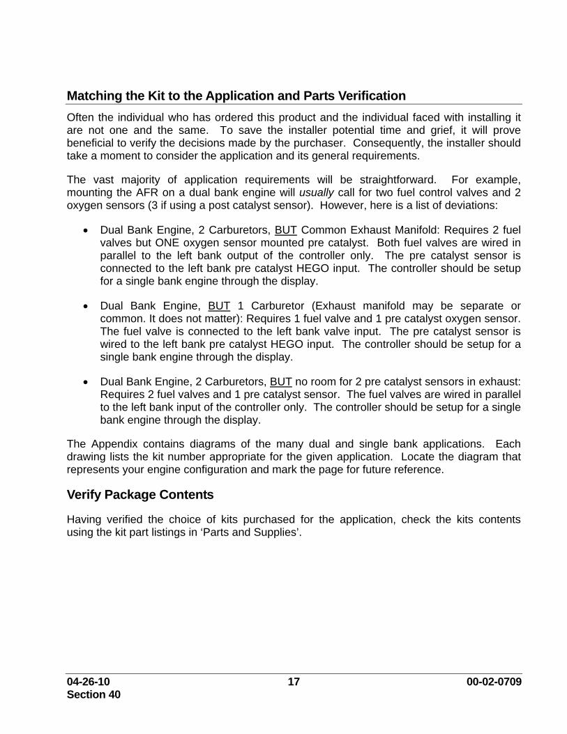
Matching the Kit to the Application and Parts Verification Often the individual who has ordered this product and the individual faced with installing it are not one and the same. To save the installer potential time and grief, it will prove beneficial to verify the decisions made by the purchaser. Consequently, the installer should take a moment to consider the application and its general requirements.
The vast majority of application requirements will be straightforward. For example, mounting the AFR on a dual bank engine will usually call for two fuel control valves and 2 oxygen sensors (3 if using a post catalyst sensor). However, here is a list of deviations:
• Dual Bank Engine, 2 Carburetors, BUT Common Exhaust Manifold: Requires 2 fuel valves but ONE oxygen sensor mounted pre catalyst. Both fuel valves are wired in parallel to the left bank output of the controller only. The pre catalyst sensor is connected to the left bank pre catalyst HEGO input. The controller should be setup for a single bank engine through the display.
• Dual Bank Engine, BUT 1 Carburetor (Exhaust manifold may be separate or common. It does not matter): Requires 1 fuel valve and 1 pre catalyst oxygen sensor. The fuel valve is connected to the left bank valve input. The pre catalyst sensor is wired to the left bank pre catalyst HEGO input. The controller should be setup for a single bank engine through the display.
• Dual Bank Engine, 2 Carburetors, BUT no room for 2 pre catalyst sensors in exhaust: Requires 2 fuel valves and 1 pre catalyst sensor. The fuel valves are wired in parallel to the left bank input of the controller only. The controller should be setup for a single bank engine through the display.
The Appendix contains diagrams of the many dual and single bank applications. Each drawing lists the kit number appropriate for the given application. Locate the diagram that represents your engine configuration and mark the page for future reference.
Verify Package Contents
Having verified the choice of kits purchased for the application, check the kits contents using the kit part listings in ‘Parts and Supplies’.
04-26-10 18 00-02-0709 Section 40
General Guidelines for Mounting the TK Valve Required tools and hardware:
• Necessary tools for the removal of air and fuel piping and associated supports (pipe wrenches; hand tools, tubing bending and cutting tools)
• Drill and pipe taps to install fuel piping into fuel and air inlet system
• Required pipe nipples, fittings and tubing to modify fuel piping
• Necessary pipe fitting in the high pressure fuel piping to accept connections to the fuel control valve
• Pipe thread sealant
• OEM gaskets and/or o-rings for engine’s air and fuel system
• Support bracket (if required) for TK fuel control valve The connections required for the TK Valve will require tubing fittings, tubing, and possibly a bracket. Fittings may need to be added to the fuel plumbing, and intake air plumbing, or pipes in the fuel plumbing and intake air plumbing will need to be drilled and tapped for pipe threads for the tubing connections for the supply pressure to the TK Valve, and the outlet of the TK Valve into the intake air piping going into the carburetor / mixer.
The TK valve controls the flow of an auxiliary stream of high pressure fuel, obtained by tapping into the fuel line before the “final cut” or “ounce” regulator. This auxiliary fuel is injected into the engine before the carburetor/mixer on the air-inlet side. Do not tie injection point into any balance lines. This statement also includes balance lines on naturally aspirated engines when equipped. (Please Note: Some naturally aspirated engines now use a balance line to compensate for pressure drop across the air intake filter. Do not tie into these.) Such a strategy relies on you to "ballpark" the desired air/fuel ratio by adjusting the carburetor load screw. Thereafter, the controller fine tunes the air/fuel ratio about this point.
WARNING: Fuel flow into the engine when not running or during shutdown by using the ignition system (thereby allowing the engine to pull fuel though the engine as it spins down) can result in fuel filling the intake manifold where it could be ignited by a backfire or flowing to the exhaust system and catalytic converter (if present). This fuel could be ignited by the high temperatures found in the exhaust and could result in damage to the engine, associated equipment and could cause personal injury or death. It may also escape to atmosphere either through the air intake or through the exhaust thereby creating a hazardous atmosphere in the area.
04-26-10 19 00-02-0709 Section 40
The electrically actuated fuel control valves supplied with this product are designed to control fuel flow only. They are not designed to replace a fuel shut-off valve or a fuel shut-off system. Therefore the product relies on the installation and use of an automatically closing fuel shut-off valve (user supplied) to stop fuel flow during and after engine shutdown and is necessary for safe product use. Such valves are widely available.
Automatic/semi-automatic fuel shut-off valve(s) are mandated by National Fire Protection Association’s “NFPA 37 – Standard for the Installation and Use of Stationary Combustion Engines and Gas Turbines.”
To prevent catalyst and/or engine damage, most engine manufactures recommend a specific engine shutdown procedure. Consult your engine manufacture for these procedures. If the procedures are not available, a general rule to follow would be to 1st turn off the engine’s fuel system and then turn off the ignition system 5 to 10 seconds later. This would allow any remaining air/fuel mixture to be combusted in the cylinders rather than in the exhaust system.
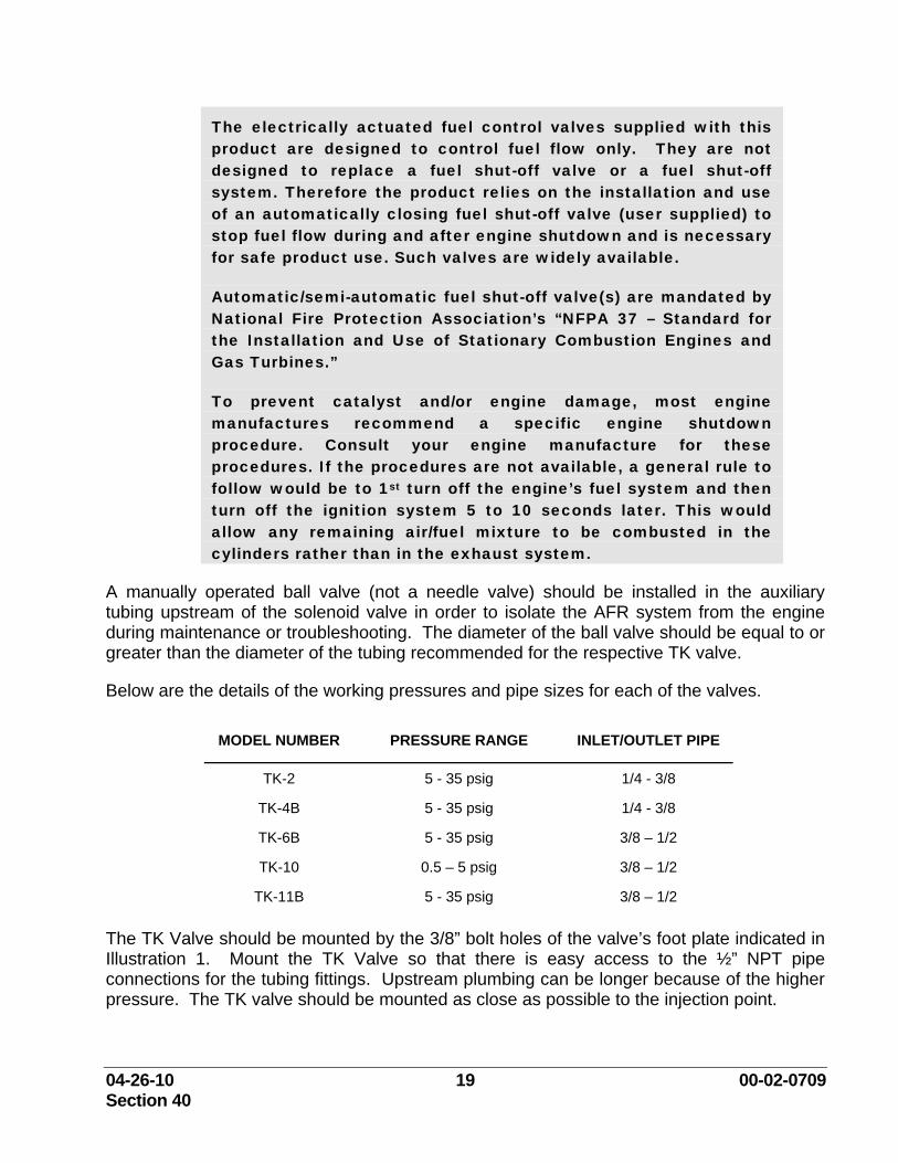
A manually operated ball valve (not a needle valve) should be installed in the auxiliary tubing upstream of the solenoid valve in order to isolate the AFR system from the engine during maintenance or troubleshooting. The diameter of the ball valve should be equal to or greater than the diameter of the tubing recommended for the respective TK valve.
Below are the details of the working pressures and pipe sizes for each of the valves.
MODEL NUMBER PRESSURE RANGE INLET/OUTLET PIPE
TK-2 5 - 35 psig 1/4 - 3/8
TK-4B 5 - 35 psig 1/4 - 3/8
TK-6B 5 - 35 psig 3/8 – 1/2
TK-10 0.5 – 5 psig 3/8 – 1/2
TK-11B 5 - 35 psig 3/8 – 1/2 The TK Valve should be mounted by the 3/8” bolt holes of the valve’s foot plate indicated in Illustration 1. Mount the TK Valve so that there is easy access to the ½” NPT pipe connections for the tubing fittings. Upstream plumbing can be longer because of the higher pressure. The TK valve should be mounted as close as possible to the injection point.
04-26-10 20 00-02-0709 Section 40
It is import to remember that the valve’s coil should be mounted in an upright position (12 o’clock position) to prevent damage to the coil caused by normal engine vibration.
The outlet tubing (piping) should never be connected to the regulator’s balance line. The location of the fuel inlet to the plumbing and the outlet to the intake air stream should not be in the bottom of those pipes, so any incidental liquids will not enter the tubing. The tubing used is typically stainless steel, with the appropriate fittings. The tubing should be properly de-burred, and free of debris. Any debris can damage the TK Valve.
The electrical connection is by a short pigtail of wire coming out of a ½” female conduit fitting. The upper housing with the conduit fitting can be rotated in any orientation.
Prior to the installation of any conduit or piping, remove the coil from the valve by removing the “E” clip from the top of the valve. Do not apply any lateral force to the coil or coil tower during the installation of the piping. Do not disassemble the valve any further than removal of the coil. Any further disassembly of the valve will void the warranty of the valve.
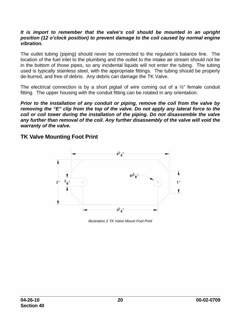
TK Valve Mounting Foot Print
414"
314"
2" 38" 1"
Ø38"
Illustration 2 TK Valve Mount Foot Print
04-26-10 21 00-02-0709 Section 40
General Guidelines for Mounting the Full Authority (FA) Valve
Required tools and hardware:
• Necessary tools for the removal of piping and associated supports (pipe wrenches; hand tools)
• Required pipe nipples and fittings to modify fuel piping
• Necessary pipe cutting and threading equipment
• Pipe thread sealant
• OEM gaskets and/or o-rings for engine’s fuel system
• Support bracket (if required) for Full Authority fuel control valve
WARNING: Fuel flow into the engine when not running or during shutdown by using the ignition system (thereby allowing the engine to pull fuel though the engine as it spins down) can result in fuel filling the intake manifold where it could be ignited by a backfire or flowing to the exhaust system and catalytic converter (if present). There it could be ignited by the high temperatures sometimes present. It may also escape to atmosphere either through the air intake or through the exhaust thereby creating a hazardous atmosphere in the area.
The electrically actuated fuel control valves supplied with this product are designed to control fuel flow only. They are not designed to replace a fuel shut-off valve or a fuel shut-off system. Therefore the product relies on the installation and use of an automatically closing fuel shut-off valve (user supplied) to stop fuel flow during and after engine shutdown and is necessary for safe product use. Such valves are widely available.
Automatic/semi-automatic fuel shut-off valve(s) are mandated by National Fire Protection Association’s “NFPA 37 – Standard for the Installation and Use of Stationary Combustion Engines and Gas Turbines.”
04-26-10 22 00-02-0709 Section 40
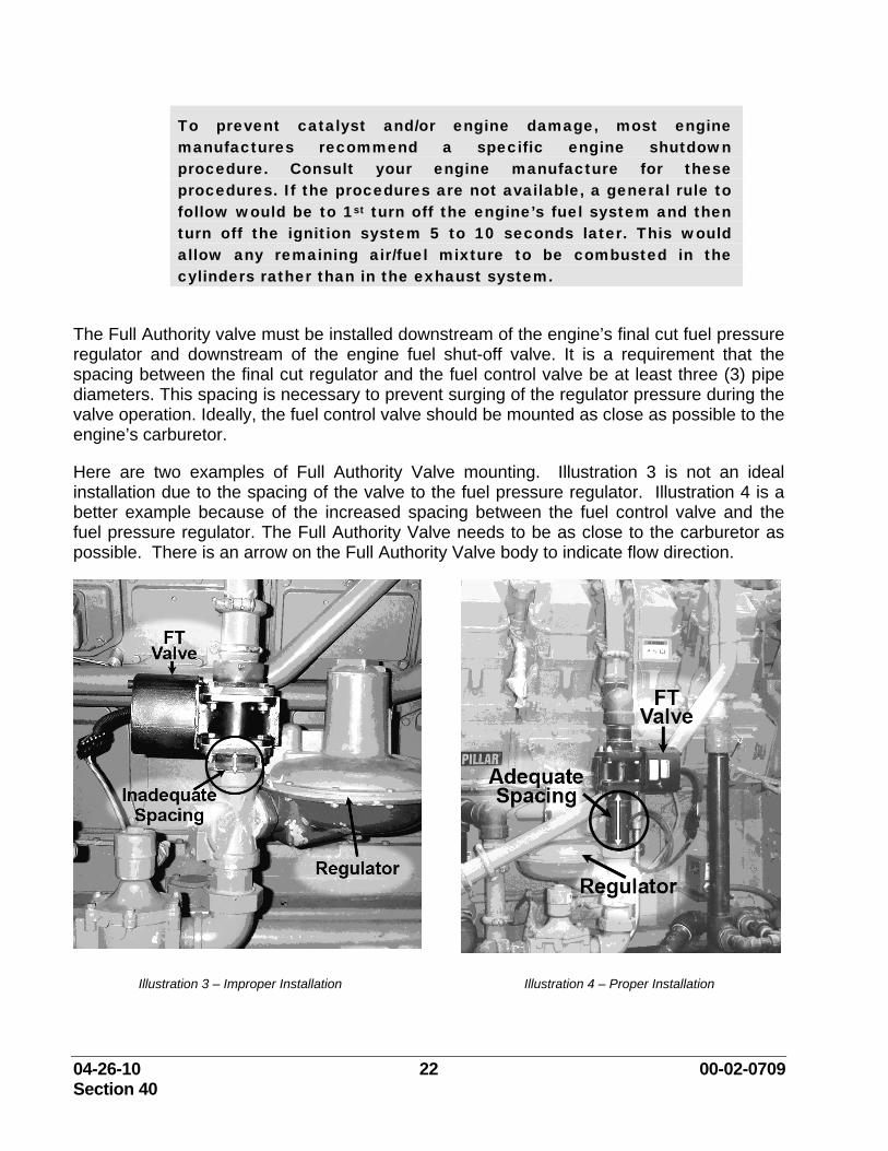
To prevent catalyst and/or engine damage, most engine manufactures recommend a specific engine shutdown procedure. Consult your engine manufacture for these procedures. If the procedures are not available, a general rule to follow would be to 1st turn off the engine’s fuel system and then turn off the ignition system 5 to 10 seconds later. This would allow any remaining air/fuel mixture to be combusted in the cylinders rather than in the exhaust system.
The Full Authority valve must be installed downstream of the engine’s final cut fuel pressure regulator and downstream of the engine fuel shut-off valve. It is a requirement that the spacing between the final cut regulator and the fuel control valve be at least three (3) pipe diameters. This spacing is necessary to prevent surging of the regulator pressure during the valve operation. Ideally, the fuel control valve should be mounted as close as possible to the engine’s carburetor.
Here are two examples of Full Authority Valve mounting. Illustration 3 is not an ideal installation due to the spacing of the valve to the fuel pressure regulator. Illustration 4 is a better example because of the increased spacing between the fuel control valve and the fuel pressure regulator. The Full Authority Valve needs to be as close to the carburetor as possible. There is an arrow on the Full Authority Valve body to indicate flow direction.
Illustration 3 – Improper Installation Illustration 4 – Proper Installation
04-26-10 23 00-02-0709 Section 40
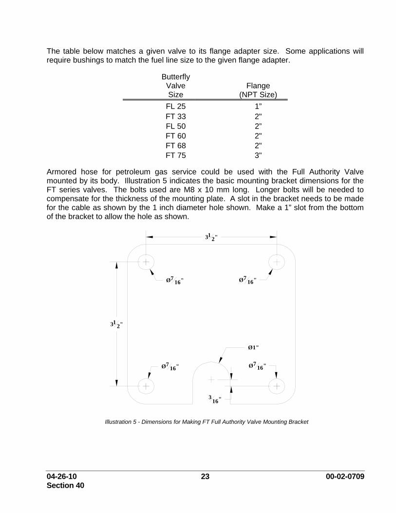
The table below matches a given valve to its flange adapter size. Some applications will require bushings to match the fuel line size to the given flange adapter.
Butterfly Valve Size
Flange (NPT Size)
FL 25 1” FT 33 2" FL 50 2” FT 60 2" FT 68 2" FT 75 3"
Armored hose for petroleum gas service could be used with the Full Authority Valve mounted by its body. Illustration 5 indicates the basic mounting bracket dimensions for the FT series valves. The bolts used are M8 x 10 mm long. Longer bolts will be needed to compensate for the thickness of the mounting plate. A slot in the bracket needs to be made for the cable as shown by the 1 inch diameter hole shown. Make a 1” slot from the bottom of the bracket to allow the hole as shown.
Ø716"
Ø716"
312"
Ø716"
Ø1"
Ø716"
312"
316"
Illustration 5 - Dimensions for Making FT Full Authority Valve Mounting Bracket
04-26-10 24 00-02-0709 Section 40
General Guidelines for Mounting the In-Line Control (ICV) Valve
Required tools and hardware:
• Necessary tools for the removal of piping and associated supports (pipe wrenches; hand tools)
• Required pipe nipples and fittings to modify fuel piping
• Necessary pipe cutting and threading equipment
• Pipe thread sealant
• OEM gaskets and/or o-rings for engine’s fuel system
• Support bracket (if required) for Full Authority fuel control valve
WARNING: Fuel flow into the engine when not running or during shutdown by using the ignition system (thereby allowing the engine to pull fuel though the engine as it spins down) can result in fuel filling the intake manifold where it could be ignited by a backfire or flowing to the exhaust system and catalytic converter (if present). There it could be ignited by the high temperatures sometimes present. It may also escape to atmosphere either through the air intake or through the exhaust thereby creating a hazardous atmosphere in the area.
The electrically actuated fuel control valves supplied with this product are designed to control fuel flow only. They are not designed to replace a fuel shut-off valve or a fuel shut-off system. Therefore the product relies on the installation and use of an automatically closing fuel shut-off valve (user supplied) to stop fuel flow during and after engine shutdown and is necessary for safe product use. Such valves are widely available.
Automatic/semi-automatic fuel shut-off valve(s) are mandated by National Fire Protection Association’s “NFPA 37 – Standard for the Installation and Use of Stationary Combustion Engines and Gas Turbines.”
04-26-10 25 00-02-0709 Section 40
To prevent catalyst and/or engine damage, most engine manufactures recommend a specific engine shutdown procedure. Consult your engine manufacture for these procedures. If the procedures are not available, a general rule to follow would be to 1st turn off the engine’s fuel system and then turn off the ignition system 5 to 10 seconds later. This would allow any remaining air/fuel mixture to be combusted in the cylinders rather than in the exhaust system.
The In-Line Control (ICV) valve must be installed downstream of the engine’s final cut fuel pressure regulator and downstream of the engine fuel shut-off valve. It is a requirement that the spacing between the final cut regulator and the fuel control valve be at least three (3) pipe diameters. This spacing is necessary to prevent surging of the regulator pressure during the valve operation. Ideally, the fuel control valve should be mounted as close as possible to the engine’s carburetor.
It is import to remember that the valve’s coil should be mounted in a downward position (6 o’clock position) to prevent damage to the coil caused by normal engine vibration.
The electrical connection is by a short pigtail of wire coming out of a ½” female conduit fitting. The upper housing with the conduit fitting can be rotated in any orientation.
Prior to the installation of any conduit or piping, remove the coil from the valve by removing the “E” clip from the top of the valve. Do not apply any lateral force to the coil or coil tower during the installation of the piping. Do not disassemble the valve any further than removal of the coil. Any further disassembly of the valve will void the warranty of the valve.
04-26-10 26 00-02-0709 Section 40
HEGO Sensor Installation General Guidelines
Pre-Catalyst HEGO Sensor
• See ‘Installation Suggestion on Various Engine Types’.
• The pre catalyst HEGO sensor(s) should be mounted as close as practical to the engine exhaust manifold(s), after any turbo charger system.
• On any engine installation where there is a common intake or exhaust manifold, only one pre catalyst HEGO sensor will be needed.
• On applications where only one (1) pre-catalyst HEGO sensor is used, the wiring should be connected to the Left Bank connectors only.
• On engine applications with dual carburetors and dual exhaust manifolds, one pre catalyst HEGO sensor will be used for each control bank.
• The maximum allowable shell temperature (melt down point) on the sensors is 500 °F (260°C). The sensors should never be installed in areas where the ambient air is stagnant and/or where the ambient air conditions exceed 250°F (121°C). The maximum thimble temperature is 1300°F.
• When the exhaust piping is insulated, the insulation should be removed from around the sensors to prevent overheating, a minimum of 3” diameter or 3 times the thickness of the insulation, whichever is greatest.
• When the exhaust pipe is installed horizontally, sensors should only be mounted between the 1:00 and 5:00 positions or the 7:00 to 11:00 positions. If the sensor is mounted vertically at the 12:00 & 6:00 positions, premature sensor failure will occur due to excessive shell temperatures and condensation build up in the exhaust pipe after shutdown. When the exhaust pipe is mounted vertically, orientation of the sensor should be to give the sensor the best chance for the lowest ambient air temperatures.
• Sensors should be installed with a light coat of anti-seize thread lubricant and torque to 30 lb-ft (40 Nm). Care should be taken that no excess anti-seize lubricant will come in contact with the sensor thimble.
Post Catalyst HEGO Sensor (optional)
• See the Installation Layout Examples section for suggestion on various engine types
• The HEGO sensor should be mounted after the catalytic converter, as close as practical to the outlet of the converter element.
• The maximum allowable shell temperature (melt down point) on the sensors is 500 °F (260°C). The sensors should never be installed in areas where the ambient air is stagnant and/or where the ambient air conditions exceed 250°F (121°C).
04-26-10 27 00-02-0709 Section 40
• When the exhaust piping is insulated, the insulation should be removed from around the sensors to prevent overheating, a minimum of 3” diameter or 3 times the thickness of the insulation or whichever is greatest.
• The sensors should only be mounted between the 1:00 and 5:00 positions or the 7:00 to 11:00 positions. If the sensor is mounted vertically at the 12:00 or 6:00 positions, premature sensor failure will occur due to excessive shell temperatures and condensation build up in the exhaust pipe after shutdown.
• Sensors should be installed with a light coat of anti-seize thread lubricant and torque to 30 lb-ft (40 Nm). Care should be taken that no excess anti-seize lubricant will come in contact with the sensor thimble.
04-26-10 28 00-02-0709 Section 40
HEGO Sensor Mounting
For ambient temperatures less than 250°F.
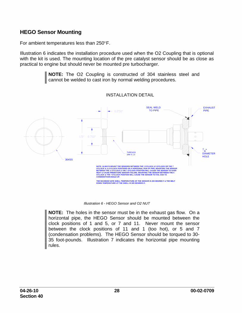
Illustration 6 indicates the installation procedure used when the O2 Coupling that is optional with the kit is used. The mounting location of the pre catalyst sensor should be as close as practical to engine but should never be mounted pre turbocharger.
NOTE: The O2 Coupling is constructed of 304 stainless steel and cannot be welded to cast iron by normal welding procedures.
INSTALLATION DETAIL
304SS
THREADS18M X 1.5
EXHAUSTPIPE
78"
DIAMETERHOLE
SEAL WELDTO PIPE
NOTE: ALWAYS MOUNT THE SENSORS BETWEEN THE 1 O'CLOCK & 5 O'CLOCK OR THE 7 O'CLOCK & 11 O'CLOCK POSITIONS ON A HORIZONAL RUN OF PIPE. MOUNTING THE SENSOR BETWEEN THE 11 O'CLOCK & THE 1 O'CLOCK POSITION WILL CAUSE THE SENSOR TO OVER HEAT & CAUSE PREMATURE SENSOR FAILURE. MOUNTING THE SENSOR BETWEEN THE 5 O'CLOCK & THE 7 O'CLOCK POSITION WILL CAUSE THE SENSOR TO FAIL DUE TO CONDENSTAION BUILD UP.
THE MAXIMUM SAFE SHELL TEMPERATURE OF THE SENSOR IS 250 DEGREE F & THE MELT DOWN TEMPERATURE AT THE SHELL IS 500 DEGREES F.
Illustration 6 - HEGO Sensor and O2 NUT
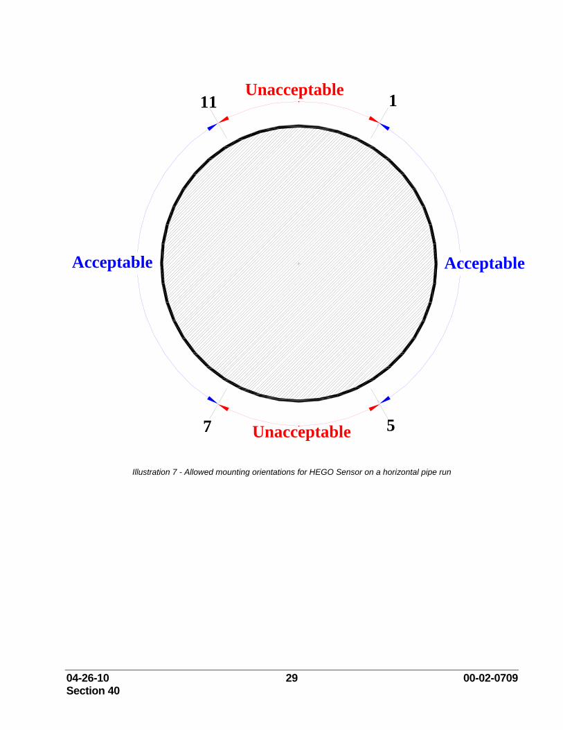
NOTE: The holes in the sensor must be in the exhaust gas flow. On a horizontal pipe, the HEGO Sensor should be mounted between the clock positions of 1 and 5, or 7 and 11. Never mount the sensor between the clock positions of 11 and 1 (too hot), or 5 and 7 (condensation problems). The HEGO Sensor should be torqued to 30-35 foot-pounds. Illustration 7 indicates the horizontal pipe mounting rules.
04-26-10 29 00-02-0709 Section 40
AcceptableAcceptable
Unacceptable
Unacceptable 1
7 5
11
Illustration 7 - Allowed mounting orientations for HEGO Sensor on a horizontal pipe run
04-26-10 30 00-02-0709 Section 40
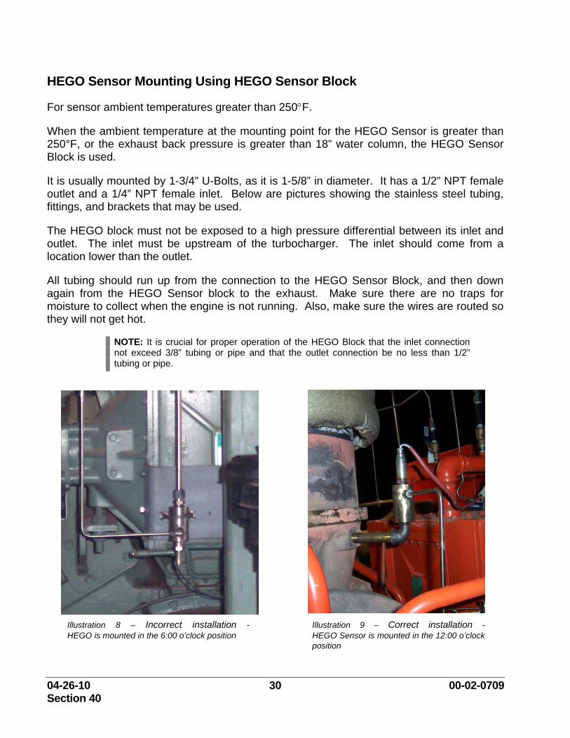
HEGO Sensor Mounting Using HEGO Sensor Block
For sensor ambient temperatures greater than 250°F.
When the ambient temperature at the mounting point for the HEGO Sensor is greater than 250°F, or the exhaust back pressure is greater than 18” water column, the HEGO Sensor Block is used.
It is usually mounted by 1-3/4” U-Bolts, as it is 1-5/8” in diameter. It has a 1/2” NPT female outlet and a 1/4” NPT female inlet. Below are pictures showing the stainless steel tubing, fittings, and brackets that may be used.
The HEGO block must not be exposed to a high pressure differential between its inlet and outlet. The inlet must be upstream of the turbocharger. The inlet should come from a location lower than the outlet.
All tubing should run up from the connection to the HEGO Sensor Block, and then down again from the HEGO Sensor block to the exhaust. Make sure there are no traps for moisture to collect when the engine is not running. Also, make sure the wires are routed so they will not get hot.
NOTE: It is crucial for proper operation of the HEGO Block that the inlet connection not exceed 3/8” tubing or pipe and that the outlet connection be no less than 1/2” tubing or pipe.
Illustration 8 – Incorrect installation - HEGO is mounted in the 6:00 o’clock position
Illustration 9 – Correct installation - HEGO Sensor is mounted in the 12:00 o’clock position
04-26-10 31 00-02-0709 Section 40
In Illustration 8, this is an example of an incorrect installation due to the orientation of the sensor. The sensor should never be mounted below the horizontal plane. Illustration 9 is an example of a properly installed HEGO Block.
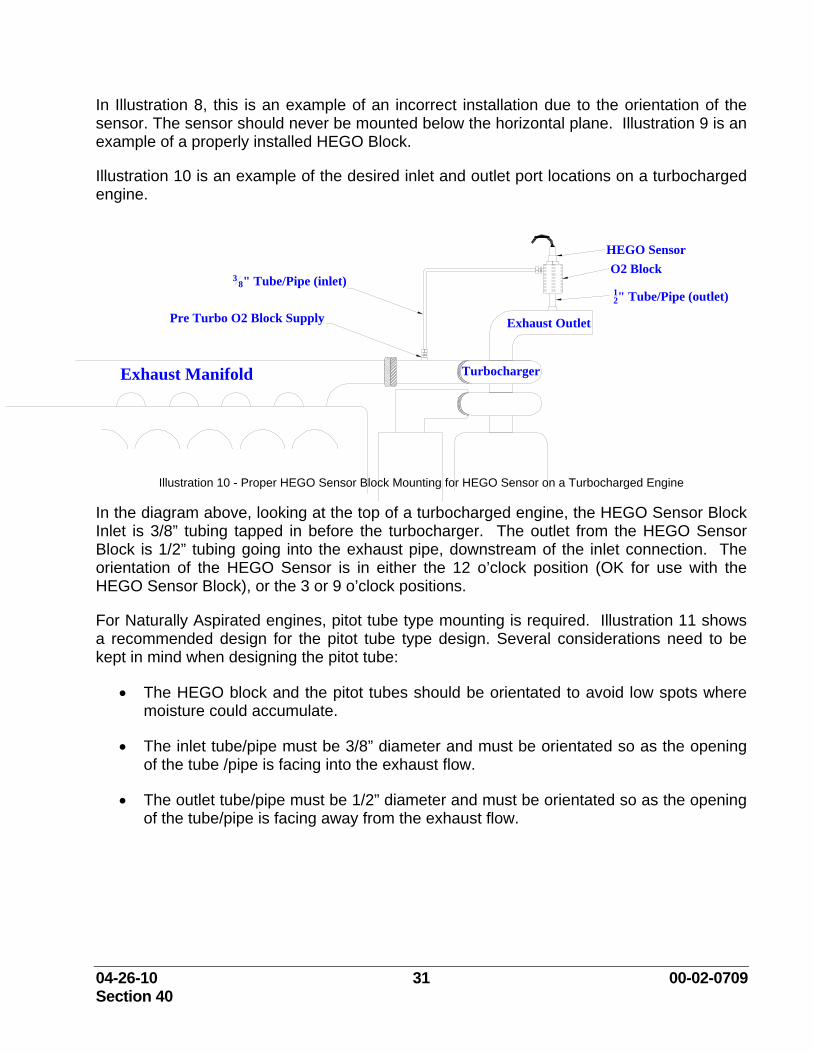
Illustration 10 is an example of the desired inlet and outlet port locations on a turbocharged engine.
Exhaust Manifold
Exhaust Outlet
O2 Block
12" Tube/Pipe (outlet)
HEGO Sensor
Pre Turbo O2 Block Supply
38" Tube/Pipe (inlet)
Turbocharger
Illustration 10 - Proper HEGO Sensor Block Mounting for HEGO Sensor on a Turbocharged Engine In the diagram above, looking at the top of a turbocharged engine, the HEGO Sensor Block Inlet is 3/8” tubing tapped in before the turbocharger. The outlet from the HEGO Sensor Block is 1/2” tubing going into the exhaust pipe, downstream of the inlet connection. The orientation of the HEGO Sensor is in either the 12 o’clock position (OK for use with the HEGO Sensor Block), or the 3 or 9 o’clock positions.
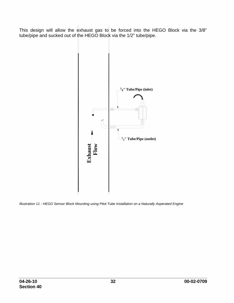
For Naturally Aspirated engines, pitot tube type mounting is required. Illustration 11 shows a recommended design for the pitot tube type design. Several considerations need to be kept in mind when designing the pitot tube:
• The HEGO block and the pitot tubes should be orientated to avoid low spots where moisture could accumulate.
• The inlet tube/pipe must be 3/8” diameter and must be orientated so as the opening of the tube /pipe is facing into the exhaust flow.
• The outlet tube/pipe must be 1/2” diameter and must be orientated so as the opening of the tube/pipe is facing away from the exhaust flow.
04-26-10 32 00-02-0709 Section 40
This design will allow the exhaust gas to be forced into the HEGO Block via the 3/8” tube/pipe and sucked out of the HEGO Block via the 1/2” tube/pipe.
Exh
aust
Fl
ow3
8" Tube/Pipe (inlet)
12" Tube/Pipe (outlet)
Illustration 11 - HEGO Sensor Block Mounting using Pitot Tube Installation on a Naturally Asperated Engine
04-26-10 33 00-02-0709 Section 40
MAP Sensor Installation
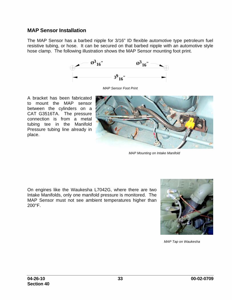
The MAP Sensor has a barbed nipple for 3/16” ID flexible automotive type petroleum fuel resistive tubing, or hose. It can be secured on that barbed nipple with an automotive style hose clamp. The following illustration shows the MAP Sensor mounting foot print.
3916"
Ø316" Ø3
16"
MAP Sensor Foot Print
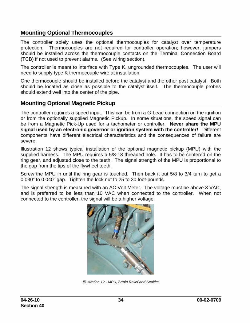
A bracket has been fabricated to mount the MAP sensor between the cylinders on a CAT G3516TA. The pressure connection is from a metal tubing tee in the Manifold Pressure tubing line already in place.
MAP Mounting on Intake Manifold
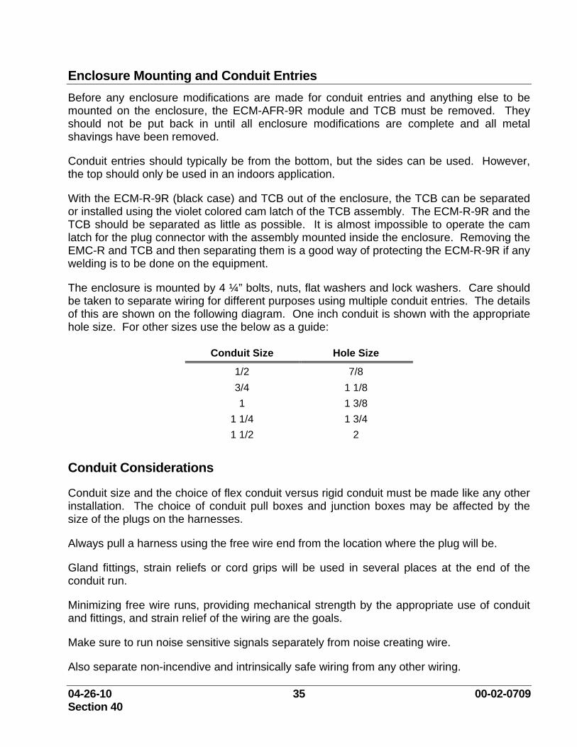
On engines like the Waukesha L7042G, where there are two Intake Manifolds, only one manifold pressure is monitored. The MAP Sensor must not see ambient temperatures higher than 200°F. MAP Tap on Waukesha
04-26-10 34 00-02-0709 Section 40
Mounting Optional Thermocouples The controller solely uses the optional thermocouples for catalyst over temperature protection. Thermocouples are not required for controller operation; however, jumpers should be installed across the thermocouple contacts on the Terminal Connection Board (TCB) if not used to prevent alarms. (See wiring section). The controller is meant to interface with Type K, ungrounded thermocouples. The user will need to supply type K thermocouple wire at installation. One thermocouple should be installed before the catalyst and the other post catalyst. Both should be located as close as possible to the catalyst itself. The thermocouple probes should extend well into the center of the pipe.
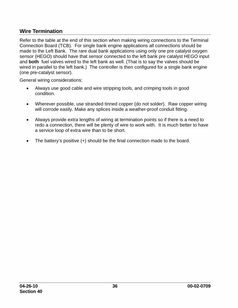
Mounting Optional Magnetic Pickup The controller requires a speed input. This can be from a G-Lead connection on the ignition or from the optionally supplied Magnetic Pickup. In some situations, the speed signal can be from a Magnetic Pick-Up used for a tachometer or controller. Never share the MPU signal used by an electronic governor or ignition system with the controller! Different components have different electrical characteristics and the consequences of failure are severe. Illustration 12 shows typical installation of the optional magnetic pickup (MPU) with the supplied harness. The MPU requires a 5/8-18 threaded hole. It has to be centered on the ring gear, and adjusted close to the teeth. The signal strength of the MPU is proportional to the gap from the tips of the flywheel teeth. Screw the MPU in until the ring gear is touched. Then back it out 5/8 to 3/4 turn to get a 0.030” to 0.040” gap. Tighten the lock nut to 25 to 30 foot-pounds. The signal strength is measured with an AC Volt Meter. The voltage must be above 3 VAC, and is preferred to be less than 10 VAC when connected to the controller. When not connected to the controller, the signal will be a higher voltage.
Illustration 12 - MPU, Strain Relief and Sealtite
04-26-10 35 00-02-0709 Section 40
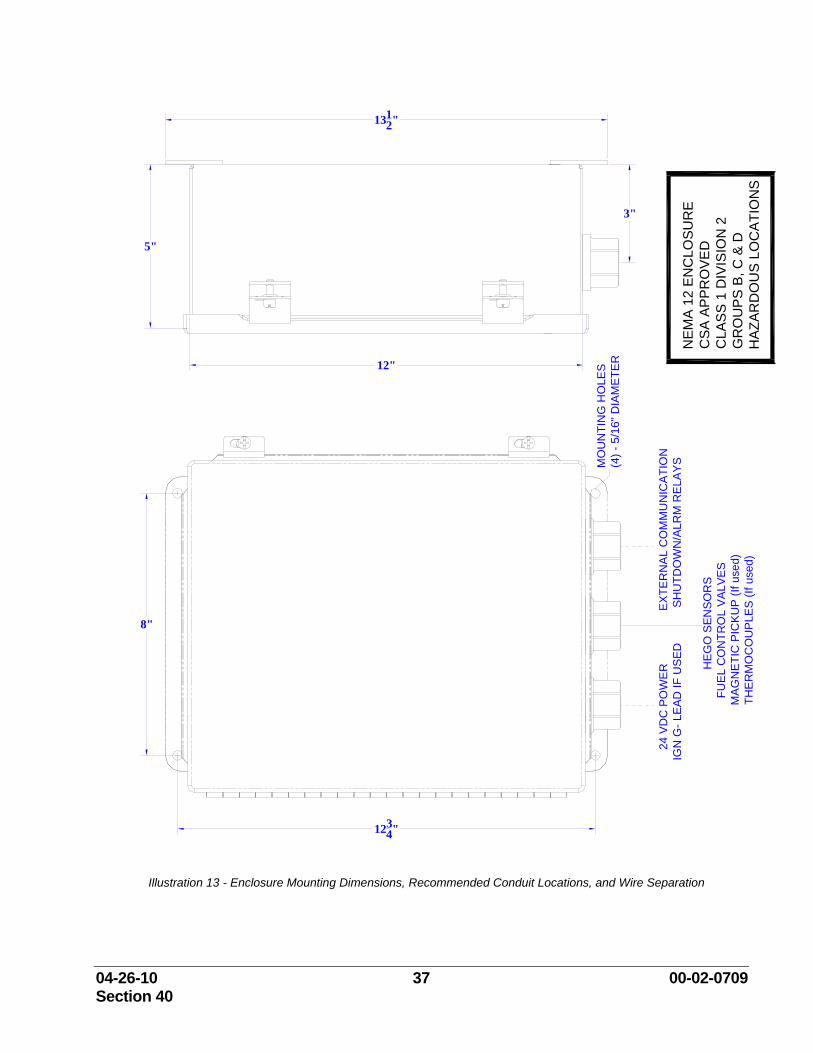
Enclosure Mounting and Conduit Entries Before any enclosure modifications are made for conduit entries and anything else to be mounted on the enclosure, the ECM-AFR-9R module and TCB must be removed. They should not be put back in until all enclosure modifications are complete and all metal shavings have been removed.
Conduit entries should typically be from the bottom, but the sides can be used. However, the top should only be used in an indoors application.
With the ECM-R-9R (black case) and TCB out of the enclosure, the TCB can be separated or installed using the violet colored cam latch of the TCB assembly. The ECM-R-9R and the TCB should be separated as little as possible. It is almost impossible to operate the cam latch for the plug connector with the assembly mounted inside the enclosure. Removing the EMC-R and TCB and then separating them is a good way of protecting the ECM-R-9R if any welding is to be done on the equipment.
The enclosure is mounted by 4 ¼” bolts, nuts, flat washers and lock washers. Care should be taken to separate wiring for different purposes using multiple conduit entries. The details of this are shown on the following diagram. One inch conduit is shown with the appropriate hole size. For other sizes use the below as a guide:
Conduit Size Hole Size
1/2 7/8 3/4 1 1/8 1 1 3/8
1 1/4 1 3/4 1 1/2 2
Conduit Considerations
Conduit size and the choice of flex conduit versus rigid conduit must be made like any other installation. The choice of conduit pull boxes and junction boxes may be affected by the size of the plugs on the harnesses.
Always pull a harness using the free wire end from the location where the plug will be.
Gland fittings, strain reliefs or cord grips will be used in several places at the end of the conduit run.
Minimizing free wire runs, providing mechanical strength by the appropriate use of conduit and fittings, and strain relief of the wiring are the goals.
Make sure to run noise sensitive signals separately from noise creating wire.
Also separate non-incendive and intrinsically safe wiring from any other wiring.
04-26-10 36 00-02-0709 Section 40
Wire Termination Refer to the table at the end of this section when making wiring connections to the Terminal Connection Board (TCB). For single bank engine applications all connections should be made to the Left Bank. The rare dual bank applications using only one pre catalyst oxygen sensor (HEGO) should have that sensor connected to the left bank pre catalyst HEGO input and both fuel valves wired to the left bank as well. (That is to say the valves should be wired in parallel to the left bank.) The controller is then configured for a single bank engine (one pre-catalyst sensor). General wiring considerations:
• Always use good cable and wire stripping tools, and crimping tools in good condition.
• Wherever possible, use stranded tinned copper (do not solder). Raw copper wiring will corrode easily. Make any splices inside a weather-proof conduit fitting.
• Always provide extra lengths of wiring at termination points so if there is a need to redo a connection, there will be plenty of wire to work with. It is much better to have a service loop of extra wire than to be short.
• The battery’s positive (+) should be the final connection made to the board.
04-26-10 37 00-02-0709 Section 40
MO
UN
TIN
G H
OLE
S(4
) - 5
/16"
DIA
ME
TER
24
VD
C P
OW
ER
IGN
G- L
EAD
IF U
SE
D
EX
TER
NA
L C
OM
MU
NIC
ATI
ON
S
HU
TDO
WN
/ALR
M R
ELA
YS
H
EG
O S
EN
SO
RS
FU
EL
CO
NTR
OL
VALV
ESM
AG
NET
IC P
ICK
UP
(If u
sed)
THE
RM
OC
OU
PLE
S (I
f use
d)
1234"
8"
5"
12"
1312"
3"
NE
MA
12 E
NC
LOS
UR
EC
SA
APP
RO
VED
C
LAS
S 1
DIV
ISIO
N 2
GR
OU
PS
B, C
& D
HA
ZAR
DO
US
LO
CA
TIO
NS
Illustration 13 - Enclosure Mounting Dimensions, Recommended Conduit Locations, and Wire Separation
04-26-10 38 00-02-0709 Section 40
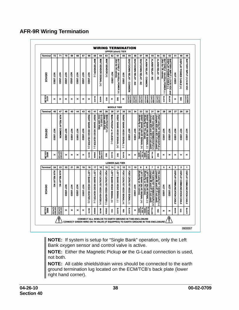
AFR-9R Wiring Termination
NOTE: If system is setup for “Single Bank” operation, only the Left Bank oxygen sensor and control valve is active. NOTE: Either the Magnetic Pickup or the G-Lead connection is used, not both. NOTE: All cable shields/drain wires should be connected to the earth ground termination lug located on the ECM/TCB’s back plate (lower right hand corner).
04-26-10 39 00-02-0709 Section 40
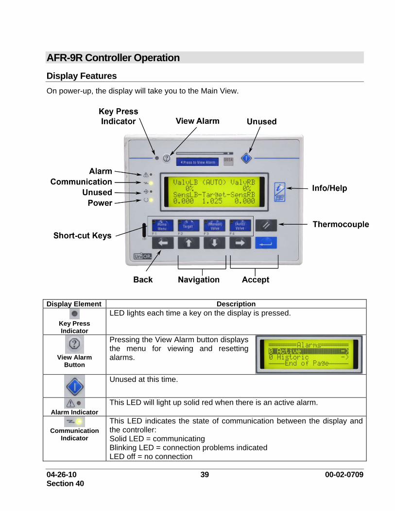
AFR-9R Controller Operation Display Features On power-up, the display will take you to the Main View.
Display Element Description
Key Press Indicator
LED lights each time a key on the display is pressed.
View Alarm
Button
Pressing the View Alarm button displays the menu for viewing and resetting alarms.
Unused at this time.
Alarm Indicator
This LED will light up solid red when there is an active alarm.
Communication
Indicator
This LED indicates the state of communication between the display and the controller: Solid LED = communicating Blinking LED = connection problems indicated LED off = no connection
04-26-10 40 00-02-0709 Section 40
Display Element Description
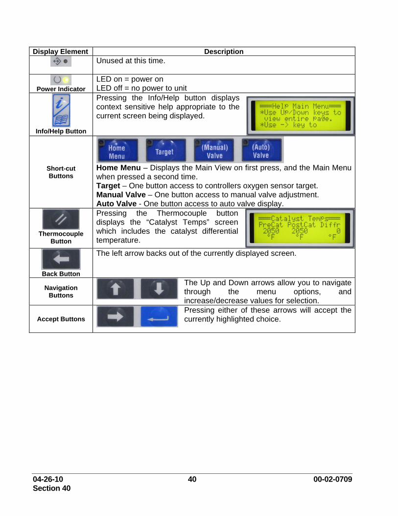
Unused at this time.
Power Indicator
LED on = power on LED off = no power to unit
Info/Help Button
Pressing the Info/Help button displays context sensitive help appropriate to the current screen being displayed.
Short-cut Buttons
Home Menu – Displays the Main View on first press, and the Main Menu when pressed a second time. Target – One button access to controllers oxygen sensor target. Manual Valve – One button access to manual valve adjustment. Auto Valve - One button access to auto valve display.
Thermocouple
Button
Pressing the Thermocouple button displays the “Catalyst Temps” screen which includes the catalyst differential temperature.
Back Button
The left arrow backs out of the currently displayed screen.
Navigation Buttons
The Up and Down arrows allow you to navigate through the menu options, and increase/decrease values for selection.
Accept Buttons Pressing either of these arrows will accept the currently highlighted choice.
04-26-10 41 00-02-0709 Section 40
AFR-9R Menus
Home Menu
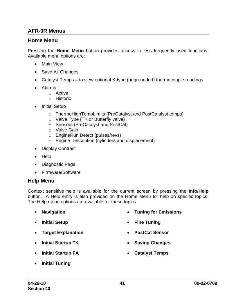
Pressing the Home Menu button provides access to less frequently used functions. Available menu options are:
• Main View
• Save All Changes
• Catalyst Temps – to view optional K-type (ungrounded) thermocouple readings
• Alarms o Active o Historic
• Initial Setup
o ThermoHighTempLimits (PreCatalyst and PostCatalyst temps) o Valve Type (TK or Butterfly valve) o Sensors (PreCatalyst and PostCat) o Valve Gain o EngineRun Detect (pulses/revs) o Engine Description (cylinders and displacement)
• Display Contrast
• Help
• Diagnostic Page
• Firmware/Software
Help Menu
Context sensitive help is available for the current screen by pressing the Info/Help button. A Help entry is also provided on the Home Menu for help on specific topics. The Help menu options are available for these topics:
• Navigation
• Initial Setup
• Target Explanation
• Initial Startup TK
• Initial Startup FA
• Initial Tuning
• Tuning for Emissions
• Fine Tuning
• PostCat Sensor
• Saving Changes
• Catalyst Temps
04-26-10 42 00-02-0709 Section 40
Navigation
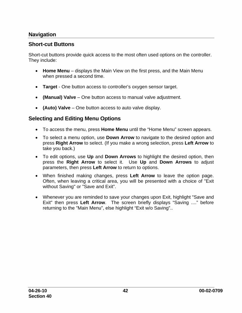
Short-cut Buttons
Short-cut buttons provide quick access to the most often used options on the controller. They include:
• Home Menu – displays the Main View on the first press, and the Main Menu when pressed a second time.
• Target - One button access to controller’s oxygen sensor target.
• (Manual) Valve – One button access to manual valve adjustment.
• (Auto) Valve – One button access to auto valve display.
Selecting and Editing Menu Options
• To access the menu, press Home Menu until the “Home Menu” screen appears.
• To select a menu option, use Down Arrow to navigate to the desired option and press Right Arrow to select. (If you make a wrong selection, press Left Arrow to take you back.)
• To edit options, use Up and Down Arrows to highlight the desired option, then press the Right Arrow to select it. Use Up and Down Arrows to adjust parameters, then press Left Arrow to return to options.
• When finished making changes, press Left Arrow to leave the option page. Often, when leaving a critical area, you will be presented with a choice of "Exit without Saving" or "Save and Exit”.
• Whenever you are reminded to save your changes upon Exit, highlight "Save and Exit" then press Left Arrow. The screen briefly displays “Saving ....” before returning to the "Main Menu”, else highlight “Exit w/o Saving”..
04-26-10 43 00-02-0709 Section 40
Initial Setup Controller Configuration Using the display and keypad to configure the controller, press Home Menu, then scroll down and select “Initial Setup”. Follow the guidelines below to edit the configuration options.
• ThermoHighTempLimits: Set Pre Catalyst and Post Catalyst thermocouple temperature trip points. We recommend the default value (1250°F) for the optional thermocouples. Ignore these settings if not using. Note: If thermocouples are not used, the thermocouple connections on the Terminal Connection Board must be jumpered together to avoid alarms. (See wiring section for details.)
• Valve Type: Select TK Valve if using small solenoid valve mounted in an auxiliary fuel line or FA Valve if using large butterfly valve mounted in main fuel line.
1. If FA Valve is selected, enter the Cranking POS (position) and Minimum Limit. Start with factory default of 0% for Minimum Limit and 50% for cranking position. The cranking position may need to be adjusted to suit engine. (See starting engine with FA Valve)
• Sensors: If you are on a dual bank engine, change the “# of Pre Catalyst” sensors to (2). If on a dual bank engine, but using only one pre catalyst sensor, set this to a value of (1). The latter type of application is treated as a single bank engine. (The left and right bank valves should both be connected to the left bank.)
• Leave the “PostCatSens” (off) for initial setup even if using this optional feature.
• Gain: The "Valve Gain" comes factory set at 20% -- a suitable value for most applications. We recommend trying the factory setting before making any adjustments.
Note: The gain controls how severe the controller corrects for the error from the target. If it is set too high, the controller becomes heavy-handed and will over-correct and may cause engine oscillation.
• EngineRun Detect: “Pulses-per-revolution” is an important parameter: Calculate the pulses-per-revolution the controller will see and change this value accordingly. The controller uses the engine RPM to determine the engine status: Engine Stopped: Less than 25 RPM Engine Cranking: 25-450 RPM Engine Running: Greater than 450 RPM Once the engine is running, RPM is used in conjunction with manifold pressure to determine engine load.
04-26-10 44 00-02-0709 Section 40
• Engine Description: Enter “# Cylinders” and “Displacement” in Liters. To convert from cubic inch displacement to liter displacement divide cubic inch displacement by 61.
Initial Tuning Verify Engine Condition First!
IMPORTANT! It cannot be overly stressed that an Air/Fuel ratio controller will not solve engine related issues. Moreover, Air/Fuel ratio controllers, in general, can actually magnify underlying engine problems such as slight misfires. Tuning for emission with a problematic engine is futile. Simply put, proceeding beyond this section with a poorly running engine is a waste of your time.
Verify the engine and all of its components are in good working order:
• all cylinders have good compression
• valves are adjusted to factory specifications
• spark plugs are in good condition, properly gapped and torqued
• gaskets are good
• ignition timing is set at factory specifications
• carburetor/mixer & regulators are in good working order and the fuel pressures are set to factory specifications.
Finally, keep in mind that all catalyst manufacturers recommend new or freshly overhauled engines to be run through a break in period before installing the catalysts.
04-26-10 45 00-02-0709 Section 40
Fuel Pressure Check 1. As a reference, the fuel pressure supplied to the regulator(s) and carburetor(s)
should be checked prior to the commissioning of the system. In most cases, the fuel pressures should be adjusted to the engine manufacturer’s recommendations. There will be instances where the fuel pressure may need to deviate from the OEM settings in order to better meet the desired exhaust emissions control. These pressure readings will be read at different points depending on whether the Butterfly (full authority) or the TK (supplemental) valves are used.
a. If the Butterfly – Full Authority (FA) Valve is used, the fuel pressure will be measured between the final cut regulator and the Butterfly (FA) Valve. The fuel pressure will always be measured between the fuel pressure and the air pressure applied to the regulator. On turbocharged engine, the manometer will be connected to the regulator’s outlet side and the air side will be connected to the carburetor’s inlet air somewhere between the turbocharger and the carburetor air horn, refer to illustration 13. On naturally aspirated engines (non-turbo charged), there are two possible measurement styles depending on whether the regulator is equipped with a balance line between the carburetor’s air inlet and the air side of the regulator or whether the engine is equipped with a non-balanced regulator. If a naturally aspirated engine is using a balanced regulator, refer to illustration 14 for the recommended measuring method. For non balanced regulators, refer to illustration 14 for the recommended measuring method.
b. If the TK Valve is used, several different measurement methods can be used depending on whether the engine is turbocharged, naturally aspirated with balanced regulator or naturally aspirated without a balanced regulator. On turbocharged engine, the manometer will be connected to the regulator’s outlet side and the air side will be connected to the carburetor’s inlet air somewhere between the turbocharger and the carburetor air horn, refer to illustration 15. On naturally aspirated engines (non-turbo charged), there are two possible measurement styles depending on whether the regulator is equipped with a balance line between the carburetor’s air inlet and the air side of the regulator or whether the engine is equipped with a non-balanced regulator. If a naturally aspirated engine is using a balanced regulator, refer to illustration 16 for the recommended measuring method. For non balanced regulators, refer to illustration 16 for the recommended measuring method.
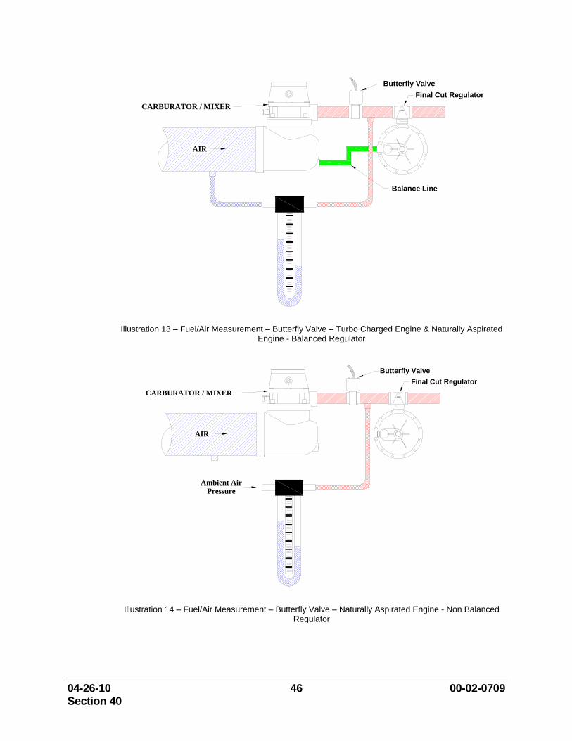
04-26-10 46 00-02-0709 Section 40
CARBURATOR / MIXER
AIR
Final Cut RegulatorButterfly Valve
Balance Line
Illustration 13 – Fuel/Air Measurement – Butterfly Valve – Turbo Charged Engine & Naturally Aspirated Engine - Balanced Regulator
CARBURATOR / MIXER
AIR
Final Cut RegulatorButterfly Valve
Ambient Air Pressure
Illustration 14 – Fuel/Air Measurement – Butterfly Valve – Naturally Aspirated Engine - Non Balanced Regulator
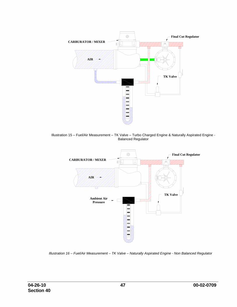
04-26-10 47 00-02-0709 Section 40
Final Cut Regulator
AIR
CARBURATOR / MIXER
TK Valve
Illustration 15 – Fuel/Air Measurement – TK Valve – Turbo Charged Engine & Naturally Aspirated Engine - Balanced Regulator
Final Cut Regulator
AIR
CARBURATOR / MIXER
TK ValveAmbient Air
Pressure
Illustration 16 – Fuel/Air Measurement – TK Valve – Naturally Aspirated Engine - Non Balanced Regulator
04-26-10 48 00-02-0709 Section 40
Initial Tuning When Using TK Valve(s) When the controller is correctly tracking the targeted air/fuel set point, the TK valve must have sufficient travel to open and close in order to compensate for variations in the engine, operation, load and ambient conditions.
For example, if the controller were to determine the engine was drifting lean, it would try to open the valve(s). This would not be possible if the valve(s) was already fully open, and would result in an alarm for Left (or Right) Bank Rich Limit. In a case where the controller might need to close the valve(s) (lean out the engine) resulting in the valve(s) being fully closed, the controller will display the alarm Left (or Right) Bank Lean Limit. In either case, the carburetor(s) and/or fuel pressure are out of the range of control. The procedure given below seeks to avoid this scenario.
Adjusting the Carburetor(s) and Fuel Pressure for TK Valve The following instructions will guide you through adjusting the carburetor(s) and fuel pressure (if necessary) so that the TK valve(s) operate around 70% open with a target of 1.025 at full load. (1.025 is a good starting value). If the engine cannot be brought to full load then this 70% valve position should be adjusted down 5% for every 20% the engine is operated less than full load. (i.e. If engine at 60% load then use a valve position of 60%.)
• With the post catalyst sensor off, and manual ball valve(s) closed, start engine and bring to maximum load.
• Adjust the engine’s fuel pressure to the manufacture’s specification. In some cases, the fuel pressure may need to be adjusted slightly higher than OEM specification in order to achieve the proper excess exhaust oxygen concentration required.
• Press “Manual” Valve and set TK valve(s) to 0% open.
• Open manual ball valve(s).
• Gradually open the TK valve(s) until they are at 70% open. It may be necessary to lean the carburetors if the engine becomes too rich.
• Adjust carburetor(s) until pre-cat sensor values on Main View screen are equal to approximately 1.025 (a good ballpark target) with the valve(s) at 70% open.
NOTE: Richening carburetor will increase sensor reading. Leaning carburetor will decrease sensor reading. If adjusting the carburetor does not yield a sufficient change, it may be necessary to adjust the fuel pressure as well.
• Once satisfied, adjust the pre catalyst target to the default value to the desired setting.
• Press (Auto) Valve and wait for valve(s) to begin tracking in stable position.

04-26-10 49 00-02-0709 Section 40
• If valve(s) do not remain at approximately 70%, adjust carburetor(s) with controller in Auto mode until valve(s) track near 70%.
NOTE: Richening carburetor(s) will cause the controller to compensate by closing the valve(s) while leaning carburetor(s) will cause the opposite effect.
• When finished, select "Save All Changes" from Home Menu.
• When a catalyst and emissions analyzer are both available read "Tuning for Emissions".
04-26-10 50 00-02-0709 Section 40
Initial Tuning When Using Full Authority (FA) Butterfly Valve(s) The cranking position for the Butterfly valve must be determined in order for the engine to start. Next, the engine's fuel system must be brought into the operating range of the controller.
When the controller is correctly tracking the targeted air/fuel set point, the FA valve(s) must have sufficient travel to open and close in order to compensate for variations in the engine. If the controller were to determine the engine was drifting lean it would normally open the valve(s) to richen the fuel mixture. However, this would not be possible if the valve(s) were already fully open, resulting in an alarm for Left (or Right) Bank Rich Limit. Thus the controller would be outside its range of control and the carburetor and/or fuel pressure would require adjustment. (Such alarms can be ignored during the setup procedure.) The following procedures for determining valve cranking position and adjusting the carburetors and fuel pressure, seek to avoid this scenario.
Adjusting the Carburetor(s) and Fuel Pressure for Full Authority (FA) Butterfly Valve The following instructions will guide you through adjusting the carburetor(s) and fuel pressure (if necessary) so that the Full Authority (FA) valve(s) operate around 70% open with a target of 1.025 at full load. (1.025 is a good starting value). If the engine cannot be brought to full load then this 70% valve position should be adjusted down 5% for every 20% the engine is operated less than full load. (i.e. If engine at 60% load then use a valve position of 60%.)
• With the engine running, press “Manual” Valve.
• Adjust the engine’s fuel pressure to the manufacture’s specification. In some cases, the fuel pressure may need to be adjusted slightly higher than OEM specification in order to achieve the proper excess exhaust oxygen concentration required.
• Adjust the valve(s) to 70% open.
• Gradually increase the load on the engine until maximum load has been achieved.
• With the valve(s) manually set at 70%, adjust the carburetor(s) until the pre catalyst sensor values on the Main View screen are approximately 1.025 (A good ballpark value).
NOTE: Richening carburetor(s) will increase sensor reading. Leaning carburetor(s) will decrease sensor reading. If adjusting the carburetor(s) does not yield a sufficient change, it may be necessary to adjust the fuel pressure as well.
• Once satisfied, adjust the pre catalyst target to the default value to the desired setting.
• Press (Auto) Valve and wait for valve(s) to begin tracking in stable position.
04-26-10 51 00-02-0709 Section 40
• If valve(s) do not remain at approximately 70%, adjust carburetor(s) with controller in Auto mode until valve(s) track near 70%.
NOTE: Richening carburetor(s) will cause the controller to compensate by closing the valve(s), while leaning carburetor(s) will cause the opposite effect.
• When finished, select "Save All Changes" from Home Menu.
• When a catalyst and emissions analyzer are both available read "Tuning for Emissions".
04-26-10 52 00-02-0709 Section 40
Determine FA Valve Cranking Position
While the engine is cranking (considered to be 25-450 rpm) the controller positions the FA Valve at the user set cranking position. To determine or modify the cranking position of the FA Valve, do the following:
• Go to "Initial Setup" and select FA Valve as the “Valve Type” and adjust the cranking position to read 50% (the default position). The cranking position is only accessible after selecting FA Valve for the valve type.
• Try to start the engine. If it seems to be starving for fuel, increase the cranking position in 5% increments. If engine is flooding decrease the cranking value in 5% decrements. To modify the cranking position, you must reselect the FA Valve for “Valve Type”.
• Once the engine starts, save these settings when exiting the “Initial Configuration” page.
• The FA Valve cranking position should not need to be adjusted during normal operation from this point forward.
04-26-10 53 00-02-0709 Section 40
Initial Tuning When Using ICV Valve(s) Next, the engine's fuel system must be brought into the operating range of the controller.
When the controller is correctly tracking the targeted air/fuel set point, the In-Line Control (ICV) valve(s) must have sufficient travel to open and close in order to compensate for variations in the engine. If the controller were to determine the engine was drifting lean it would normally open the valve(s) to richen the fuel mixture. However, this would not be possible if the valve(s) were already fully open, resulting in an alarm for Left (or Right) Bank Rich Limit. Thus the controller would be outside its range of control and the carburetor and/or fuel pressure would require adjustment. (Such alarms can be ignored during the setup procedure.) The following procedures for determining valve cranking position and adjusting the carburetors and fuel pressure, seek to avoid this scenario.
Adjusting the Carburetor(s) and Fuel Pressure for In-Line Control (ICV) Valve The following instructions will guide you through adjusting the carburetor(s) and fuel pressure (if necessary) so that the In-Line Control (ICV) valve(s) operate around 50% open with a target of 1.025 at full load. (1.025 is a good starting value). If the engine cannot be brought to full load then this 50% valve position should be adjusted down 5% for every 25% the engine is operated less than full load. (i.e. If engine at 75% load then use a valve position of 45%.)
• Prior to starting the engine, adjust the main adjusting screw to full open (extending from valve block approximately 1” and lock down the adjusting screw using the lock nut.
• Adjust the engine’s fuel pressure to the manufacture’s specification. In some cases, the fuel pressure may need to be adjusted slightly higher than OEM specification in order to achieve the proper excess exhaust oxygen concentration required. When using this valve, Compliance Controls recommends that the fuel pressure be adjusted 3” to 5” above the engine’s required fuel pressure in order to give the valve the widest control range possible.
• With the engine running, press “Manual” Valve. • Adjust the valve(s) to 50% open.
• Gradually increase the load on the engine until maximum load has been achieved.
• With the valve(s) manually set at 50%, adjust the carburetor’s load screw to approximately midpoint between rich and lean.
• Adjust the valve’s main adjusting screw until the pre catalyst sensor values on the Main View screen are approximately 1.025 (A good ballpark value).
04-26-10 54 00-02-0709 Section 40
NOTE: Richening carburetor(s) will increase sensor reading. Leaning carburetor(s) will decrease sensor reading. If adjusting the carburetor(s) does not yield a sufficient change, it may be necessary to adjust the fuel pressure as well.
• Once satisfied, adjust the pre catalyst target to the default value to the desired setting.
• Press (Auto) Valve and wait for valve(s) to begin tracking in stable position.
• If valve(s) do not remain at approximately 50%, adjust the valve’s main adjusting screw with controller in Auto mode until valve(s) track near 50%.
NOTE: Screwing out the adjusting screw will cause the controller to compensate by closing the valve(s), while screwing in on the adjusting screw will cause the opposite effect.
• When finished, select "Save All Changes" from Home Menu.
• When a catalyst and emissions analyzer are both available read "Tuning for Emissions".
04-26-10 55 00-02-0709 Section 40
Tuning for Emissions Tuning for Emissions - Without Optional Post Catalyst Sensor Skip to next section if using optional post catalyst sensor.
The controller is first treated as a single setpoint controller by determining the proper target for optimum catalyst performance at maximum load. All targets in the nine point pre catalyst table are set equal to this value. (The optimum target at other loads will not be far from this value.)
Next, the proper targets for mid and low loads are determined. Simultaneously, the Nominal Valve positions for these load points are entered into the Nominal Valve Table in order increase the speed of the controller's response to step changes in engine load.
Determine Target Value
Using a catalyst and emissions analyzer, follow these instructions to determine an overall target value yielding best catalyst performance at maximum load.
• Bring engine to maximum operating load.
• Select the target in the right, bottom portion of the table. Highlight RPM3 (the highest rpm setting) and adjust this to be approx 50 rpm more than the maximum engine speed.
• Next, read the engine manifold pressure to the left of the table. Add 2 psi to this and enter this value into the table for MAP3 (the highest MAP pressure that will be seen.)
• With controller in Auto mode, and using an analyzer, begin to adjust the 4 targets in the lower right corner of the table always keeping them equal to each other.
NOTE: Richening the engine (opening the valve(s)) decreases NOx but increases CO. Leaning the engine (closing the valve(s)) increases NOx, but decreases CO.
• Having found the proper target, set all targets of the table to this value.
• If necessary, adjust the carburetor(s) to make the valve(s) track at 70% once again with this new target.
• Next, press Target and select “NominalValvePos”.
• Read the current mass air flow rate (in this case this would be your engine's maximum mass air flow rate) add 2 to this value and enter this into the 3rd (last) point of the table.
• Read the actual valve command being sent by the controller in the lower left portion of the screen (if dual bank split the difference of the two) and enter this value for the nominal valve position of slot 3. This is the “ballpark” valve position when the controller is tracking the optimum target at this mass air flow rate.
04-26-10 56 00-02-0709 Section 40
Refine Target Values
The following instructions will guide you through refining target values of the table in order to achieve best catalyst performance at midrange and low loads.
• If possible bring engine down to a midrange load.
• Give the controller time to stabilize.
• Press Target and select “Adjust Targets”. Read the engine RPM and MAP values, pick a value slightly less than these and enter them into the table for RPM2 and MAP2 respectively.
• Using the readouts for the engine's RPM and manifold pressure, determine those targets bracketing your current engine’s operating point. While using the analyzer, adjust these target values to achieve best catalyst performance at this midrange load.
• Once ideal conditions are met, switch to the “NominalValvePos” table, read current mass airflow and enter a value into the table for slot 2 that is slightly below this. Next, read the controller's current valve command and enter this into the table.
• Finally bring engine to a minimum load. Set the RPM1 and MAP2 values on the table accordingly. Please note, engine operation below the values you have set for RPM1 and MAP1 will result in the controller leaving closed loop mode and setting the valve to a position based solely on that entered into the NominalValvePos table.
• Navigate to "Save All Settings" on the Home Menu and select.
• For future reference you may want to record all table values. To make this easier, the table may be viewed "at a glance" by pressing Target and scrolling to "ViewPreCat Targets” table.
04-26-10 57 00-02-0709 Section 40
Tuning for Emissions with a Post Catalyst Sensor. The controller is first treated as a single set point controller with the post catalyst sensor switched off. The optimum pre catalyst target value is found for maximum load and all targets are set to this value. Next the post catalyst sensor is turned on. The optimum value for the post catalyst sensor is found and all post catalyst targets are set equal to this value.
Finally, the targets for pre and post catalyst sensors are optimized for mid and low engine loads while simultaneously populating the nominal valve table for fast controller response.
Determine Target Value
Using a catalyst and emissions analyzer, follow these instructions to determine an overall target value yielding best catalyst performance at maximum load.
• With the post catalyst sensor switched off (accessed through the Initial Configuration page), bring engine to maximum operating load.
• Select the target in the right, bottom portion of the table. Highlight RPM3 (the highest rpm setting) and adjust this to be approx 50 rpm more than the maximum engine speed.
• Next read engine manifold pressure, add 2 psi to this and enter this value into the table for MAP3 (the highest MAP pressure that will be seen.)
• With the controller in Auto mode, and using an analyzer, begin to adjust the 4 targets in the lower right corner of the table always keeping them equal to each other. Note that richening the engine (opening the valve(s)) decreases NOx, but increases CO. Leaning the engine (closing the valve(s)) increases NOx, but decreases CO.
• Having found the proper target, set all targets of the table to this value.
• Now turn on the post catalyst sensor (accessed through the Initial Configuration page).
• Look at the Main View screen to see the post catalyst sensor reading, and enter this value as the post catalyst target value for the four point in the lower right section of the table. (Same as was done for the pre catalyst target.)
• Using the analyzer, adjust these four post catalyst targets rich or lean (keeping them equal) to achieve best catalyst performance. Between each adjustment, switch to the Main View screen to determine the affect of the post catalyst control loop bias on the pre catalyst set point by glancing at the Pre Catalyst offset value. This shows how much the post catalyst control loop is adding too or subtracting from the pre catalyst target. The post catalyst control loop is only allowed a maximum offset of + or - .010. When the offset value has reached these limits, further adjustment of the post catalyst target in the respective direction will have no further effect, at which point it is necessary to adjust the pre catalyst target value. If any pre catalyst adjustment is made, be sure to keep all pre catalyst target values equal at this stage.
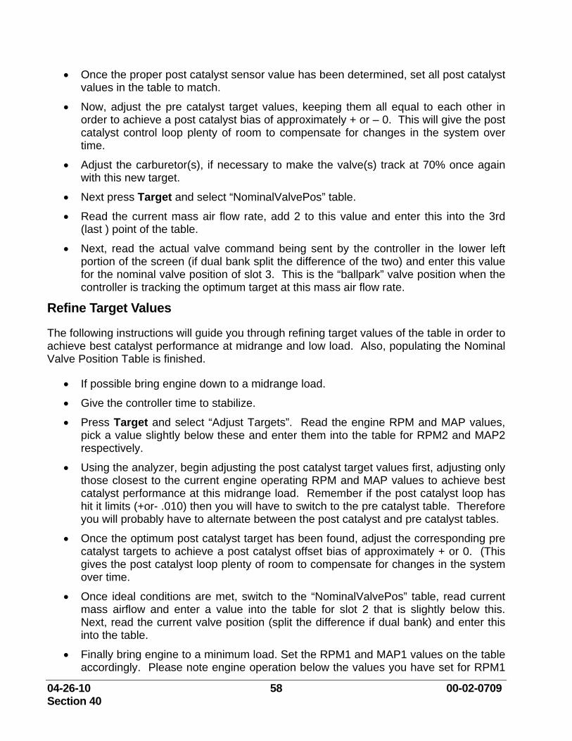
04-26-10 58 00-02-0709 Section 40
• Once the proper post catalyst sensor value has been determined, set all post catalyst values in the table to match.
• Now, adjust the pre catalyst target values, keeping them all equal to each other in order to achieve a post catalyst bias of approximately + or – 0. This will give the post catalyst control loop plenty of room to compensate for changes in the system over time.
• Adjust the carburetor(s), if necessary to make the valve(s) track at 70% once again with this new target.
• Next press Target and select “NominalValvePos” table.
• Read the current mass air flow rate, add 2 to this value and enter this into the 3rd (last ) point of the table.
• Next, read the actual valve command being sent by the controller in the lower left portion of the screen (if dual bank split the difference of the two) and enter this value for the nominal valve position of slot 3. This is the “ballpark” valve position when the controller is tracking the optimum target at this mass air flow rate.
Refine Target Values
The following instructions will guide you through refining target values of the table in order to achieve best catalyst performance at midrange and low load. Also, populating the Nominal Valve Position Table is finished.
• If possible bring engine down to a midrange load.
• Give the controller time to stabilize.
• Press Target and select “Adjust Targets”. Read the engine RPM and MAP values, pick a value slightly below these and enter them into the table for RPM2 and MAP2 respectively.
• Using the analyzer, begin adjusting the post catalyst target values first, adjusting only those closest to the current engine operating RPM and MAP values to achieve best catalyst performance at this midrange load. Remember if the post catalyst loop has hit it limits (+or- .010) then you will have to switch to the pre catalyst table. Therefore you will probably have to alternate between the post catalyst and pre catalyst tables.
• Once the optimum post catalyst target has been found, adjust the corresponding pre catalyst targets to achieve a post catalyst offset bias of approximately + or 0. (This gives the post catalyst loop plenty of room to compensate for changes in the system over time.
• Once ideal conditions are met, switch to the “NominalValvePos” table, read current mass airflow and enter a value into the table for slot 2 that is slightly below this. Next, read the current valve position (split the difference if dual bank) and enter this into the table.
• Finally bring engine to a minimum load. Set the RPM1 and MAP1 values on the table accordingly. Please note engine operation below the values you have set for RPM1
04-26-10 59 00-02-0709 Section 40
and MAP1 will result in the controller leaving closed loop mode and setting the valve to a position based solely on the value entered into the Nominal Valve table.
• Adjust the post catalyst and pre catalyst targets until optimum emissions are met.
• Switch to the Nominal Valve table and read the mass air flow rate and enter a value slightly less than this into the table.
• Save all setting after you finish.
Post Tuning for Emissions Before you leave the site:
• Navigate to the “Main Menu” and select “Save All Changes”. Otherwise they will be lost when power is cycled to the unit.
• Leave the controller with the “Main View” or “Catalyst Temps” visible.
• Verify the valve(s) are tracking on average around 70%.
• Communicate to all others the importance of not adjusting the carburetor or the fuel pressure now that the controller has been tuned.
04-26-10 60 00-02-0709 Section 40
Troubleshooting, Maintenance and Replacement Product Support The following troubleshooting guidelines are provided for you to use when corrective action is needed. However, if you need technical assistance please contact your distributor.
To find a COMPLIANCE CONTROLS Distributor in your area, please visit our web site at
www.ComplianceControls.com
CORPORATE OFFICE Tulsa, Oklahoma
5311 So. 122nd East Ave. Tulsa, OK 74146-6006 Phone – (918) 317-4100
Fax – (918) 317-4266
www.ComplianceControls.com
Email at: [email protected]
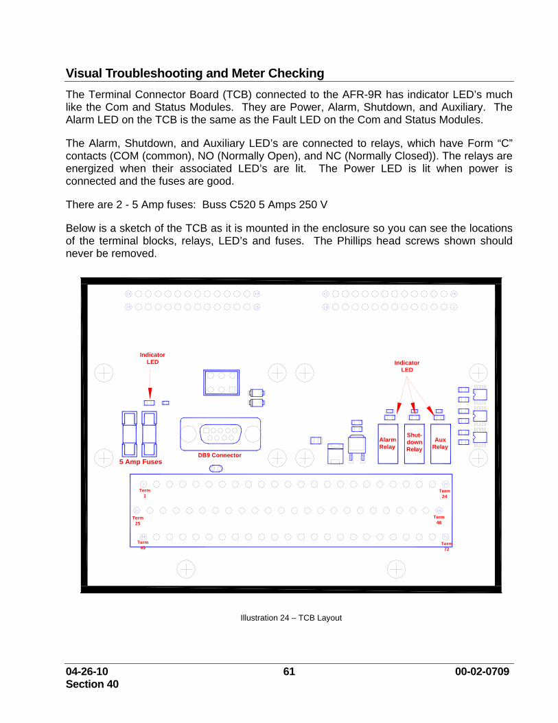
04-26-10 61 00-02-0709 Section 40
Visual Troubleshooting and Meter Checking The Terminal Connector Board (TCB) connected to the AFR-9R has indicator LED’s much like the Com and Status Modules. They are Power, Alarm, Shutdown, and Auxiliary. The Alarm LED on the TCB is the same as the Fault LED on the Com and Status Modules.
The Alarm, Shutdown, and Auxiliary LED’s are connected to relays, which have Form “C” contacts (COM (common), NO (Normally Open), and NC (Normally Closed)). The relays are energized when their associated LED’s are lit. The Power LED is lit when power is connected and the fuses are good.
There are 2 - 5 Amp fuses: Buss C520 5 Amps 250 V
Below is a sketch of the TCB as it is mounted in the enclosure so you can see the locations of the terminal blocks, relays, LED’s and fuses. The Phillips head screws shown should never be removed.
Shut-down Relay
Alarm Relay
Aux Relay
5 Amp Fuses
Term 24
Term 25
Term 1
Term 48
Term 49
Term 72
DB9 Connector
Indicator LED Indicator
LED
Illustration 24 – TCB Layout
04-26-10 62 00-02-0709 Section 40
If the Power LED is not lit, and DC power is measured with a meter at terminals 49 (Battery Input +) and 52 (Battery Input -), then check the fuses. Both fuses used are connected together. Try measuring with the red probe of the volt meter at the bottom end of the fuses, the end away from the terminal blocks and the black probe of the meter at terminal 52 or 53.
If the fuses are blown, turn off the power, remove the fuses, remove any wires from terminal 52, and use your meter measuring Ohms between the bottom end of the fuse clips and terminal 52 or 53. You should measure 20 k to 30 k Ohms.
If the reading is much lower (less than 10 Ohms), then remove any wires from terminals 16, 18, 42, and 61. If the reading goes up to the 20 k to 30 k region, then check each of the wires that were disconnected from terminals 16, 18, 42, and 61 versus earth ground.
The wires that were connected to terminals 16 (Post Cat HEGO Heater +), 18 (Left Bank HEGO Heater +) and 42 (Right Bank HEGO Heater +) should read in the neighborhood of 100 k Ohms when reading back to terminal 52 or 53.
The wire connected to terminal 61 should read in the neighborhood of 30 M Ohms when reading back to terminal 52 or 53.
If any of these wires reads low, like the reading from the fuses, then that wire, harness, or device is suspect. With those wires disconnected, again measure from the bottom of the fuses to terminal 52. If the reading is in the neighborhood of 20 k to 30 k Ohms, then the problem has been found and replacing the fuses will cure the problem after the wire, harness, or end device has been replaced.
If the low ohms reading are still present, then the ECM-AFR-9R and TCB should be returned for repair, and a new ECM-AFR-9R and TCB installed.
If the Power LED is lit, and the Shutdown LED is lit, then there are several steps to go through if a PC is not available to connect to read the problem from the Fault Display as shown below from the Display_R1, Screen No. 1, below.
With the unit powered, and running, the following list of voltage ranges are normal for the terminals listed:
NOTE: All Voltages have a tolerance of measurement. These values are given as a guideline, and are not expected to be exact. These are ball park values unless specified otherwise. 0 VDC means Power Supply minus (-). The values were measured with the black probe of the meter on terminal 52.)
04-26-10 63 00-02-0709 Section 40
1. RS-485 – 0 VDC not connected, 2 to 3 VDC and jumping when connected (polling device dependent)
2. RS-485 + 4 VDC not connected, 2 to 3 VDC and jumping when connected (polling device dependent)
3. 0 VDC 4. -5.6 VDC when not communicating, -3 to -6 and jumping when communicating with a
PC RS-232 5. -4.2 VDC when not communicating, -2 to -4 and jumping when communicating with a
PC RS-232 6. 0 VDC 7. < 40 mVDC for less than 1800 F, see chart for mV vs. deg. F voltage created by TC –
Pre Cat 8. 0 VDC 9. 0.15 VDC when below 25 RPM -- LB TK
6 VAC, 2 VDC, 312.5 Hz at 0%, running 7.6 VAC, 23 VDC, 312.5 Hz at 85 % running
11. 0 VDC 12. 0.5 to 0.8 VDC - Post Cat HEGO Signal 13. 0 VDC 14. 0.5 to 0.8 VDC - LB HEGO Signal 15. Pulse Width Modulated 100 Hz, DC reading will vary from Power Supply Plus to near
Power Supply Minus depending on duty cycle (90 % will give close to minus, and 10% will give close to plus) this is the transistor output for the PWM for the HEGO heater. When it turns off, it is Power Supply (+). When it turns on, it is close to Power Supply (-).
16. Power Supply + (9-32 VDC) -- Post Cat HEGO Heater 17. Pulse Width Modulated 100 Hz, DC reading will vary from Power Supply Plus to near
Power Supply Minus depending on duty cycle (90 % will give close to minus, and 10% will give close to plus) this is the transistor output for the PWM for the HEGO heater. When it turns off, it is Power Supply (+). When it turns on, it is close to Power Supply (-).
18. Power Supply + ( 9-32 VDC ) -- LB HEGO Heater 23. AUX RELAY NC – when relay not energized COM volts, when relay energized,
connected device not connected voltage 24. AUX RELAY NO – when relay not energized, connected device not connected voltage,
when relay energized, COM volts 25. CAN Link – 2.4 VDC not connected 26. CAN Link + 2.4 VDC not connected
04-26-10 64 00-02-0709 Section 40
30. 0 VDC 31. < 40 mVDC for less than 1800 F, see chart for mV vs. deg. F voltage created by TC –
Post Cat 32. 0 VDC 33. 0.15 VDC when below 25 RPM – RB TK l
6 VAC, 2 VDC, 312.5 Hz at 0%, running 7.6 VAC, 23 VDC, 312.5 Hz at 85 % running
38. 0 VDC 39. Mag Pick-Up +, 0.2 1- 100 VAC rms, 8 – 10,000 Hz (10 kHz) 40. 0 – 250 VDC pulsing, G Lead for Ignition Speed Signal 41. Pulse Width Modulated 100 Hz, DC reading will vary from Power Supply Plus to near
Power Supply Minus depending on duty cycle (90 % will give close to minus, and 10% will give close to plus) this is the transistor output for the PWM for the HEGO heater. When it turns off, it is Power Supply (+). When it turns on, it is close to Power Supply (-).
42. Power Supply + ( 9-32 VDC ) -- RB HEGO Heater 47. AUX RELAY COM – Power Supply +, Power Supply -, connected device common,
connected device voltage 49. Power Supply + 9 – 32 VDC Customer Power Supply Connect 50. Power Supply + 9 – 32 VDC 52. 0 VDC Customer Power Supply Connect 53. 0 VDC 54. ALARM RELAY NC – when relay not energized COM volts, when relay energized,
connected device not connected voltage 55. ALARM RELAY NO – when relay not energized, connected device not connected
voltage, when relay energized, COM volts 56. ALARM RELAY COM – Power Supply +, Power Supply -, connected device common,
connected device voltage 57. SHUTDOWN RELAY NC – when relay not energized COM volts, when relay
energized, connected device not connected voltage 58. SHUTDOWN RELAY NO – when relay not energized, connected device not connected
voltage, when relay energized, COM volts 59. SHUTDOWN RELAY COM – Power Supply +, Power Supply -, connected device
common, connected device voltage
04-26-10 65 00-02-0709 Section 40
61. Power Supply 63. 5 VDC 64. MAP signal 0 -5 DVC 65. 0 VDC
See Charts for mV vs. deg. F for Type K thermocouples and VDC vs. % Excess O2 for HEGO Sensor.
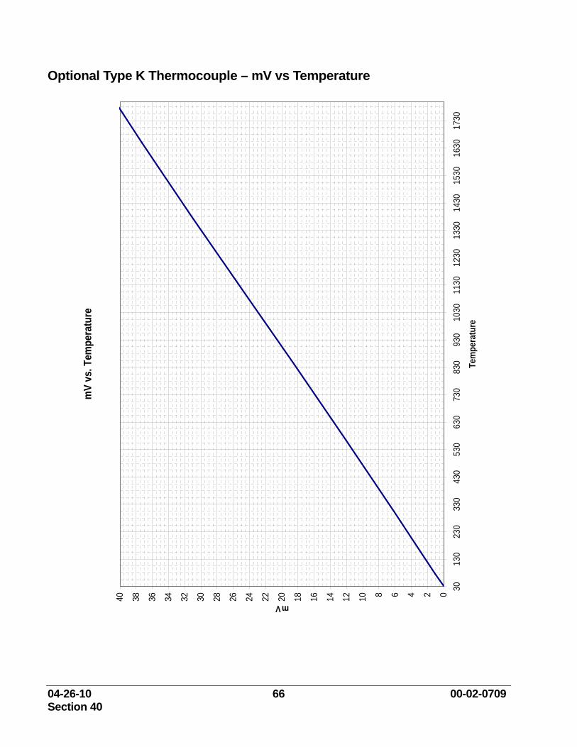
04-26-10 66 00-02-0709 Section 40
Optional Type K Thermocouple – mV vs Temperature m
V vs
. Tem
pera
ture
0246810121416182022242628303234363840
3013
023
033
043
053
063
073
083
093
010
3011
3012
3013
3014
3015
3016
3017
30
Tem
pera
ture
mV
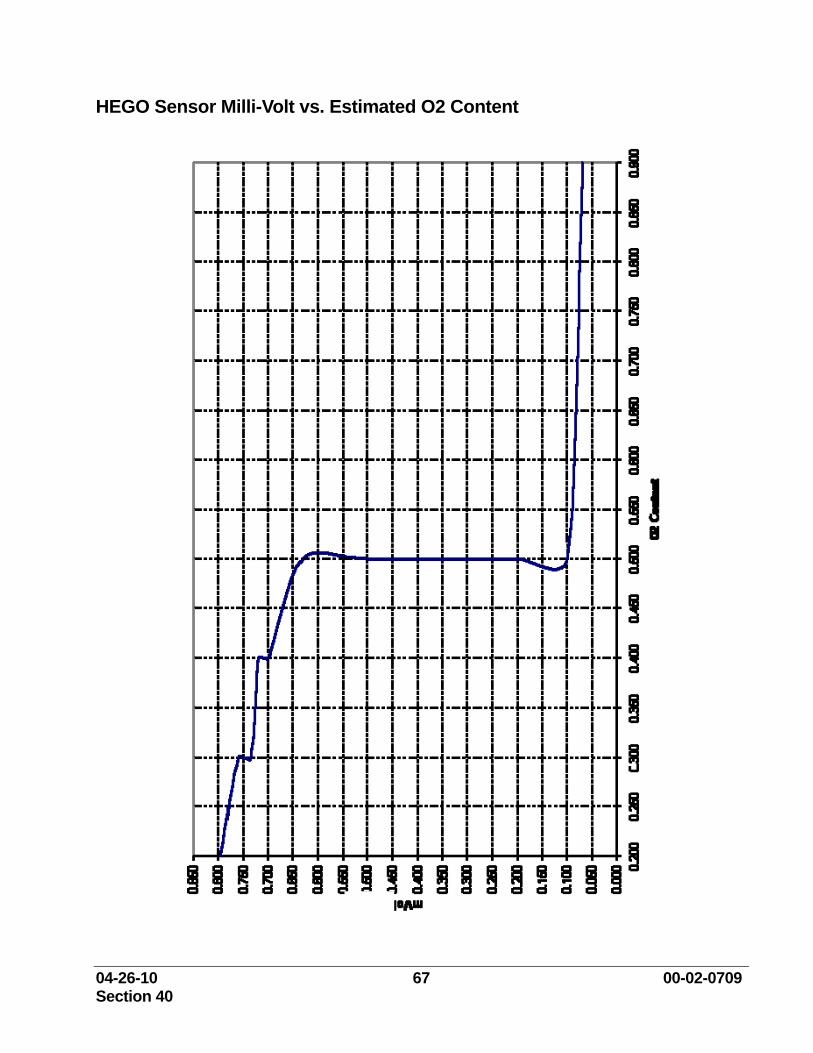
04-26-10 67 00-02-0709 Section 40
HEGO Sensor Milli-Volt vs. Estimated O2 Content
04-26-10 68 00-02-0709 Section 40
Troubleshooting Action Steps When values are read at the terminal block different than what was listed, follow these steps:
1. Disconnect the wiring at the TCB for the trouble points.
2. Disconnect the device at the other end of the wires.
3. Measure Ohms between the disconnected wires at the controller end and ground. There should never be any reading except Open Lead, or open circuit. If there are any readings showing Ohms, then that wiring, harness, or cable is shorted to ground and needs to be replaced.
4. Measure Ohms between individual wires of wiring, a harness, or a cable. The readings should always be Open Lead, or open circuit. If there are any readings of Ohms, then that wiring, harness, or cable has shorts between the wires and needs to be replaced.
If the wiring harnesses or cables pass the tests above, then the devices that were connected to the wiring harness or cable should be checked with a meter. At this point, the device is the most likely suspect. But there are a few things that can be checked.
1. Thermocouples – Check the thermocouple wire versus the metal of the sheath, or skid ground for Ohms. Ungrounded (the only kind recommended) thermocouples must show open circuit Use an independent device to read the thermocouple to get temperature readings from it to check the accuracy of the Thermocouple. Use a thermocouple simulator to put a calibrated signal into the unit. MilliVolts can be read from the thermocouple, but the reading is subject to Cold Junction Compensation, and can have large errors as compared to a thermocouple table, or the chart already shown.
2. HEGO checking The Ohms between Heater (+) and Heater (–) should be approximately 7.
3. Magnetic Pick-up 1000 Ohms
4. TK Valve Coil should measure 15 Ohms ± 1.5 Ohms.
04-26-10 69 00-02-0709 Section 40
Troubleshooting Guide Problem/Fault Trigger Point Possible Cause Correction Thermocouple 1 or 2 Open
Exhaust temperature exceeds 1800 degrees F for more than 1 second
Open or broken thermocouple wiring
Replace or repair wiring
Open or broken thermocouple probe
Replace thermocouple probe
Open connection on TCB Replace TCB
Faulty AFR control module Call Compliance Controls local support
Firmware corrupted Call Compliance Controls local support
Thermocouple 1 or 2 High Temp
Exhaust temperature exceeds user defined set point for greater than 5 seconds
Cylinder misfire Check ignition system Change spark plugs Check cylinder compression
Thermocouple bad Replace thermocouple probe Faulty AFR control module Call Compliance Controls local
support Thermocouple 1 or 2 Low Temp
Exhaust temperature less than 500 degrees F for greater than 300 seconds
Faulty thermocouple Replace thermocouple Shorted thermocouple wire Replace thermocouple wire Incorrect wire type Replace wire with type “K”
compatible wire Shorted TCB connection Replace TCB Faulty AFR control module Replace controller Firmware corrupted Call Compliance Controls local
support CJC High Voltage CJC voltage greater
than 4.95 volts DC Faulty AFR control module Call Compliance Controls local
support Firmware corrupted Call Compliance Controls local
support CJC Low Voltage CJC voltage less
than 0.050 volts DC Faulty AFR control module Call Compliance Controls local
support Firmware corrupted Call Compliance Controls local
support BP High Pressure
Barometric Pressure greater than 16.0 psia
Faulty AFR control module Replace controller Firmware corrupted Call Compliance Controls local
support BP Low Pressure Barometric Pressure
less than 8.30 psia Faulty AFR control module Replace controller Firmware corrupted Call Compliance Controls local
support Voltage High Supply voltage
greater than 32.0 volts DC - Disables Adaptive Learn - Cycle power to reset
Power supply Replace power supply Cross connection Check for cross connection with
other power supply Faulty AFR control module Replace controller Firmware corrupted Call Compliance Controls local
support
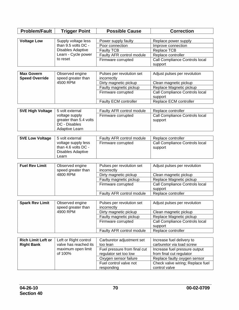
04-26-10 70 00-02-0709 Section 40
Problem/Fault Trigger Point Possible Cause Correction Voltage Low Supply voltage less
than 9.5 volts DC - Disables Adaptive Learn - Cycle power to reset
Power supply faulty Replace power supply Poor connection Improve connection Faulty TCB Replace TCB Faulty AFR control module Replace controller Firmware corrupted Call Compliance Controls local
support Max Govern Speed Override
Observed engine speed greater than 4500 RPM
Pulses per revolution set incorrectly
Adjust pulses per revolution
Dirty magnetic pickup Clean magnetic pickup Faulty magnetic pickup Replace Magnetic pickup Firmware corrupted Call Compliance Controls local
support Faulty ECM controller Replace ECM controller
5VE High Voltage 5 volt external
voltage supply greater than 5.4 volts DC - Disables Adaptive Learn
Faulty AFR control module Replace controller Firmware corrupted Call Compliance Controls local
support
5VE Low Voltage 5 volt external
voltage supply less than 4.6 volts DC - Disables Adaptive Learn
Faulty AFR control module Replace controller Firmware corrupted Call Compliance Controls local
support
Fuel Rev Limit Observed engine
speed greater than 4800 RPM
Pulses per revolution set incorrectly
Adjust pulses per revolution
Dirty magnetic pickup Clean magnetic pickup Faulty magnetic pickup Replace Magnetic pickup Firmware corrupted Call Compliance Controls local
support Faulty AFR control module Replace controller
Spark Rev Limit Observed engine
speed greater than 4900 RPM
Pulses per revolution set incorrectly
Adjust pulses per revolution
Dirty magnetic pickup Clean magnetic pickup Faulty magnetic pickup Replace Magnetic pickup Firmware corrupted Call Compliance Controls local
support Faulty AFR control module Replace controller
Rich Limit Left or Right Bank
Left or Right control valve has reached its maximum open limit of 100%
Carburetor adjustment set too lean
Increase fuel delivery to carburetor via load screw
Fuel pressure from final cut regulator set too low
Increase fuel pressure output from final cut regulator
Oxygen sensor failure Replace faulty oxygen sensor Fuel control valve not responding
Check valve wiring; Replace fuel control valve
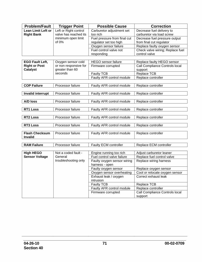
04-26-10 71 00-02-0709 Section 40
Problem/Fault Trigger Point Possible Cause Correction Lean Limit Left or Right Bank
Left or Right control valve has reached its minimum open limit of 0%
Carburetor adjustment set too rich
Decrease fuel delivery to carburetor via load screw
Fuel pressure from final cut regulator set too high
Decrease fuel pressure output from final cut regulator
Oxygen sensor failure Replace faulty oxygen sensor Fuel control valve not responding
Check valve wiring; Replace fuel control valve
EGO Fault Left, Right or Post Catalyst
Oxygen sensor cold or non responsive for greater than 60 seconds
HEGO sensor failure Replace faulty HEGO sensor Firmware corrupted Call Compliance Controls local
support Faulty TCB Replace TCB Faulty AFR control module Replace controller
COP Failure Processor failure Faulty AFR control module Replace controller Invalid interrupt Processor failure Faulty AFR control module Replace controller A/D loss Processor failure Faulty AFR control module Replace controller RT1 Loss Processor failure Faulty AFR control module Replace controller RT2 Loss Processor failure Faulty AFR control module Replace controller RT3 Loss Processor failure Faulty AFR control module Replace controller Flash Checksum Invalid
Processor failure Faulty AFR control module Replace controller
RAM Failure Processor failure Faulty ECM controller Replace ECM controller High HEGO Sensor Voltage
Not a coded fault - General troubleshooting only
Engine running too rich Adjust carburetor leaner Fuel control valve failure Replace fuel control valve Faulty oxygen sensor wiring harness - open
Replace wiring harness
Faulty oxygen sensor Replace oxygen sensor Oxygen sensor overheating Cool or relocate oxygen sensor Exhaust leak / oxygen intrusion
Correct exhaust leak
Faulty TCB Replace TCB Faulty AFR control module Replace controller Firmware corrupted Call Compliance Controls local
support
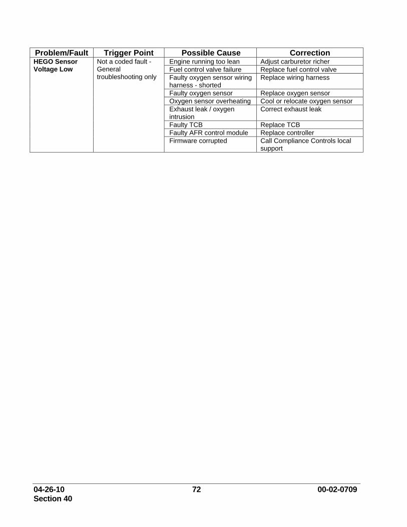
04-26-10 72 00-02-0709 Section 40
Problem/Fault Trigger Point Possible Cause Correction HEGO Sensor Voltage Low
Not a coded fault - General troubleshooting only
Engine running too lean Adjust carburetor richer Fuel control valve failure Replace fuel control valve Faulty oxygen sensor wiring harness - shorted
Replace wiring harness
Faulty oxygen sensor Replace oxygen sensor Oxygen sensor overheating Cool or relocate oxygen sensor Exhaust leak / oxygen intrusion
Correct exhaust leak
Faulty TCB Replace TCB Faulty AFR control module Replace controller Firmware corrupted Call Compliance Controls local
support
04-26-10 73 00-02-0709 Section 40
Maintenance and Replacement The AFR-9R controller and system components were designed to be very reliable in operation. Very few of the components require any maintenance; however the heated exhaust gas oxygen sensors (HEGO) and the optional thermocouple sensors have a limited life and will require regular replacement.
A regular program for engine maintenance should continue after the AFR-9R system is installed. To provide emissions compliance, the original engine systems need to be in proper working order.
Please review the warning statements, and any warnings associated with the exhaust system components. The use of certain gasket sealers (RTV), thread sealers and high temperature thread lubricants can cause poisoning of the oxygen sensors. Contact your COMPLIANCE CONTROLS distributor for a list of possible sensor poisons. The frequent replacement required for the oxygen sensor can cause these contaminants to build up relatively quickly. Excessive engine oil consumption can also cause these effects over longer periods of time.
The AFR-9R system will relieve the operator of constant carburetor tuning for emissions compliance, but consistent engine maintenance is still required. Also, if the engine is operated at widely varying loads, a single target controller may not provide adequate control. The AFR-9R can be easily upgraded to a load following, multi-target controller. Please inquire at your Compliance Controls distributor for details.
Replacement Information
The replacement of sensors will depend mainly on engine operating hours. Below is an estimated life expectancy of the AFR-9R end devices:
• HEGO Sensors – The health of the HEGO sensors are monitored by the controller and are reported as a percentage.
o These health reports may be found on the Diagnostic page of the controller.
o The HEGO sensor should be replaced once the health drops below 50%.
o If the engine is not run for a period greater than 12 months the sensor should be replaced due to the possibility of moisture saturation.
• Optional Thermocouple – 36,000 hours of engine operation or 48 months installed, whichever occurs first.
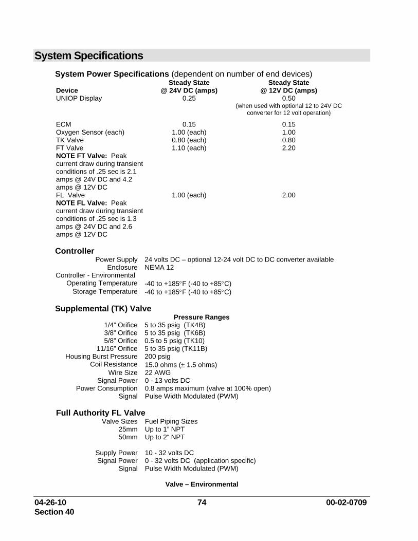
04-26-10 74 00-02-0709 Section 40
System Specifications System Power Specifications (dependent on number of end devices)
Device Steady State
@ 24V DC (amps) Steady State
@ 12V DC (amps) UNIOP Display 0.25 0.50
(when used with optional 12 to 24V DC converter for 12 volt operation)
ECM 0.15 0.15 Oxygen Sensor (each) 1.00 (each) 1.00 TK Valve 0.80 (each) 0.80 FT Valve NOTE FT Valve: Peak current draw during transient conditions of .25 sec is 2.1 amps @ 24V DC and 4.2 amps @ 12V DC
1.10 (each) 2.20
FL Valve NOTE FL Valve: Peak current draw during transient conditions of .25 sec is 1.3 amps @ 24V DC and 2.6 amps @ 12V DC
1.00 (each) 2.00
Controller
Power Supply 24 volts DC – optional 12-24 volt DC to DC converter available Enclosure NEMA 12
Controller - Environmental Operating Temperature -40 to +185°F (-40 to +85°C)
Storage Temperature -40 to +185°F (-40 to +85°C)
Supplemental (TK) Valve Pressure Ranges
1/4” Orifice 5 to 35 psig (TK4B) 3/8” Orifice 5 to 35 psig (TK6B) 5/8” Orifice 0.5 to 5 psig (TK10)
11/16” Orifice 5 to 35 psig (TK11B) Housing Burst Pressure 200 psig
Coil Resistance 15.0 ohms (± 1.5 ohms) Wire Size 22 AWG
Signal Power 0 - 13 volts DC Power Consumption 0.8 amps maximum (valve at 100% open)
Signal Pulse Width Modulated (PWM)
Full Authority FL Valve Valve Sizes Fuel Piping Sizes
25mm Up to 1” NPT 50mm Up to 2“ NPT
Supply Power 10 - 32 volts DC Signal Power 0 - 32 volts DC (application specific)
Signal Pulse Width Modulated (PWM)
Valve – Environmental
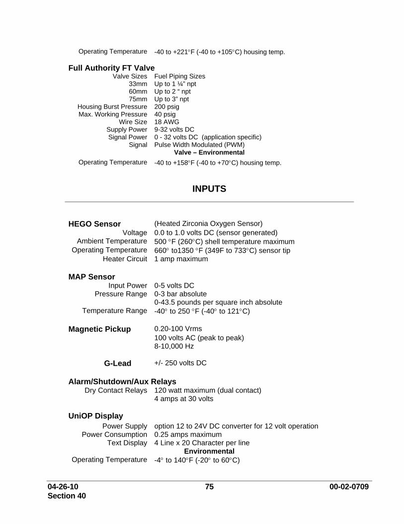
04-26-10 75 00-02-0709 Section 40
Operating Temperature -40 to +221°F (-40 to +105°C) housing temp.
Full Authority FT Valve Valve Sizes Fuel Piping Sizes
33mm Up to 1 ¼” npt 60mm Up to 2 “ npt 75mm Up to 3” npt
Housing Burst Pressure 200 psig Max. Working Pressure 40 psig
Wire Size 18 AWG Supply Power 9-32 volts DC Signal Power 0 - 32 volts DC (application specific)
Signal Pulse Width Modulated (PWM) Valve – Environmental
Operating Temperature -40 to +158°F (-40 to +70°C) housing temp.
INPUTS
HEGO Sensor (Heated Zirconia Oxygen Sensor) Voltage 0.0 to 1.0 volts DC (sensor generated)
Ambient Temperature 500 °F (260°C) shell temperature maximum Operating Temperature 660° to1350 °F (349F to 733°C) sensor tip
Heater Circuit 1 amp maximum MAP Sensor
Input Power 0-5 volts DC Pressure Range 0-3 bar absolute
0-43.5 pounds per square inch absolute Temperature Range -40° to 250 °F (-40° to 121°C)
Magnetic Pickup 0.20-100 Vrms
100 volts AC (peak to peak) 8-10,000 Hz
G-Lead +/- 250 volts DC Alarm/Shutdown/Aux Relays
Dry Contact Relays 120 watt maximum (dual contact) 4 amps at 30 volts
UniOP Display Power Supply option 12 to 24V DC converter for 12 volt operation
Power Consumption 0.25 amps maximum Text Display 4 Line x 20 Character per line
Environmental Operating Temperature -4° to 140°F (-20° to 60°C)
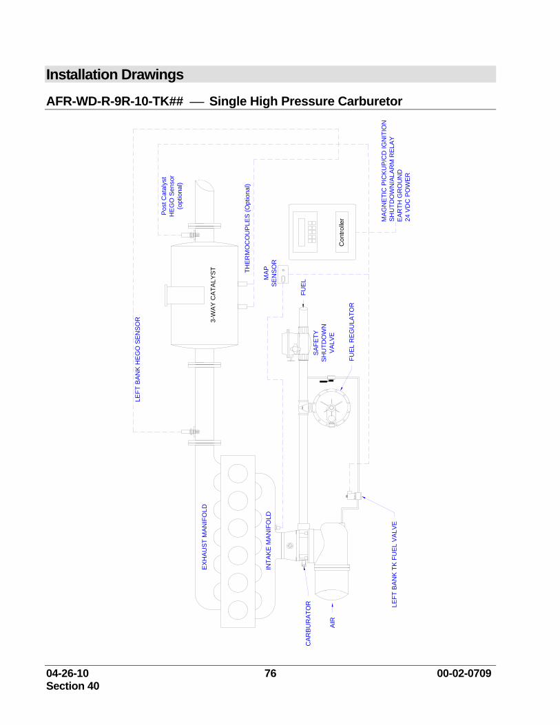
04-26-10 76 00-02-0709 Section 40
Installation Drawings
AFR-WD-R-9R-10-TK## ⎯ Single High Pressure Carburetor
FUEL
CAR
BUR
ATO
R
AIR
INTA
KE
MAN
IFO
LD
EXH
AUS
T M
ANIF
OLD
SH
UTD
OW
NS
AFE
TY
VALV
EC
ontro
ller
FUEL
RE
GU
LATO
R
THER
MO
CO
UP
LES
(Opt
iona
l)
LEFT
BA
NK
HE
GO
SEN
SOR 3-
WAY
CA
TALY
ST
LEFT
BA
NK
TK
FU
EL V
ALVE
MA
GN
ETI
C P
ICK
UP/
CD
IGN
ITIO
NS
HU
TDO
WN
/ALA
RM
RE
LAY
EAR
TH G
RO
UN
D24
VD
C P
OW
ER
MAP
SEN
SOR
Pos
t Cat
alys
tH
EG
O S
enso
r(o
ptio
nal)
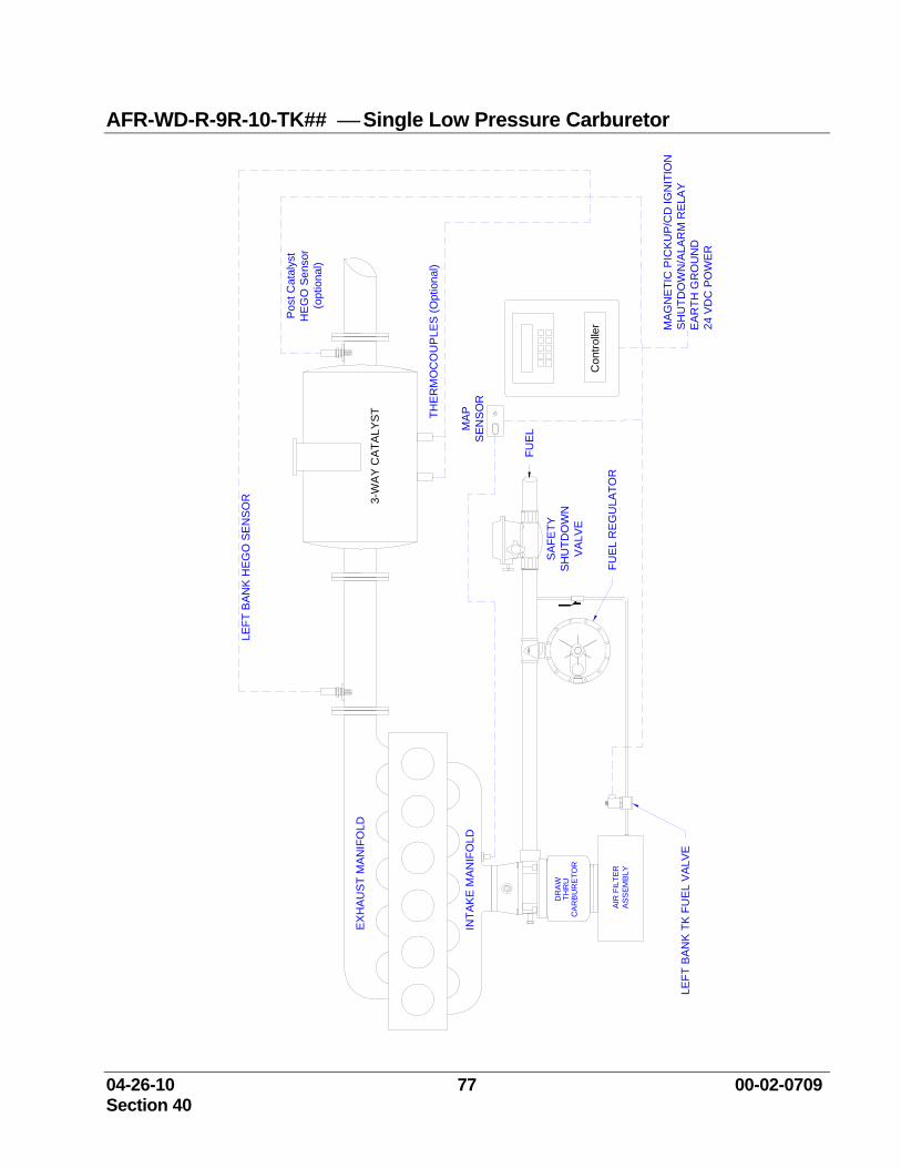
04-26-10 77 00-02-0709 Section 40
AFR-WD-R-9R-10-TK## ⎯ Single Low Pressure Carburetor
FUEL
INTA
KE
MA
NIF
OLD
EX
HA
US
T M
ANIF
OLD
SH
UTD
OW
NS
AFE
TY
VA
LVE
Con
trolle
rFU
EL
RE
GU
LATO
R
THE
RM
OC
OU
PLE
S (O
ptio
nal)
LEFT
BA
NK
HE
GO
SE
NS
OR 3-
WA
Y C
ATA
LYS
T
LEFT
BA
NK
TK
FU
EL
VALV
EM
AG
NE
TIC
PIC
KU
P/C
D IG
NIT
ION
SH
UTD
OW
N/A
LAR
M R
ELA
YE
AR
TH G
RO
UN
D24
VD
C P
OW
ER
MA
PS
ENS
OR
Pos
t Cat
alys
tH
EG
O S
enso
r(o
ptio
nal)
CA
RB
UR
ETO
R
AIR
FIL
TER
AS
SEM
BLY
THR
UD
RA
W
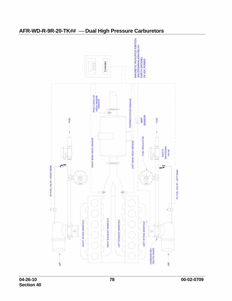
04-26-10 78 00-02-0709 Section 40
AFR-WD-R-9R-20-TK## ⎯ Dual High Pressure Carburetors
FUE
L R
EG
ULA
TOR
SH
UTD
OW
NS
AFE
TY
VA
LVE
CA
RB
UR
ETO
R /
DE
LTE
C M
IXER
AIR
LEFT
EXH
AU
ST
MAN
IFO
LD
LEFT
INTA
KE
MAN
IFO
LD
RIG
HT
EX
HA
US
T M
ANIF
OLD
RIG
HT
INTA
KE
MAN
IFO
LD
AIR
FUEL
FUEL
THE
RM
OC
OU
PLE
S (O
ptio
nal)
HE
GO
SEN
SOR
POS
T C
ATAL
YST
RIG
HT
BA
NK
HEG
O S
ENSO
R
TK F
UE
L V
ALV
E -
RIG
HT
BAN
K
LEFT
BA
NK
HE
GO
SEN
SOR
TK F
UE
L VA
LVE
- LE
FT B
ANK
Con
trolle
r
MAG
NET
IC P
ICK
UP
/CD
IGN
ITIO
NS
HU
TDO
WN
/ALA
RM
REL
AYE
AR
TH G
RO
UN
D24
VD
C P
OW
ER
(Opt
iona
l)
MA
PS
EN
SO
R
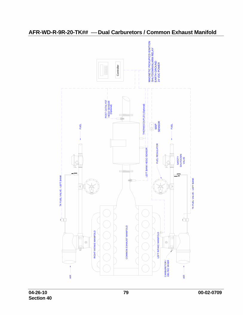
04-26-10 79 00-02-0709 Section 40
AFR-WD-R-9R-20-TK## ⎯ Dual Carburetors / Common Exhaust Manifold
FUE
L R
EG
ULA
TOR
SH
UTD
OW
NS
AFET
Y
VAL
VE
CAR
BU
RE
TOR
/ D
ELTE
C M
IXER
AIR
CO
MM
ON
EXH
AUS
T M
ANIF
OLD
LEFT
INTA
KE
MAN
IFO
LD
RIG
HT
INTA
KE
MA
NIF
OLD
AIR
FUEL
FUEL
THE
RM
OC
OU
PLE
S (O
ptio
nal)
HEG
O S
EN
SO
RP
OS
T C
ATA
LYST
TK F
UEL
VAL
VE
- LE
FT B
ANK LE
FT B
AN
K H
EG
O S
ENSO
R
TK F
UEL
VA
LVE
- LE
FT B
ANK
Con
trolle
r
MAG
NET
IC P
ICKU
P/C
D IG
NIT
ION
SH
UTD
OW
N/A
LAR
M R
ELA
YE
AR
TH G
RO
UN
D24
VD
C P
OW
ER
(Opt
iona
l)
MAP
SE
NSO
R
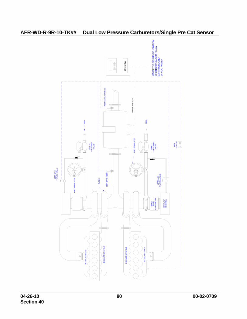
04-26-10 80 00-02-0709 Section 40
AFR-WD-R-9R-10-TK## ⎯Dual Low Pressure Carburetors/Single Pre Cat Sensor
LEFT
BAN
KTK
FU
EL V
ALVE
LEFT
BA
NK
TKL
FUE
L VA
LVE
LEFT
BA
NK
HEG
O
MAP
SE
NSO
R
INTA
KE M
ANIF
OLD
AIR
FIL
TER
ASS
EMBL
Y
CA
RB
UR
ETO
R
DR
AW
THR
U
EX
HA
US
T M
ANIF
OLD
TUR
BO
FUEL
REG
ULA
TOR
FUEL
FUEL
REG
ULA
TOR
VAL
VE
SAF
ETY
SH
UTD
OW
N
THE
RM
OC
OU
PLE
S
FUEL
SAF
ETY
SH
UTD
OW
NV
ALVE
POST
CA
TALY
ST H
EGO
Con
trolle
r
MA
GN
ETI
C P
ICK
UP/
CD
IGN
ITIO
NS
HU
TDO
WN
/ALA
RM
RE
LAY
EAR
TH G
RO
UN
D24
VD
C P
OW
ER
EX
HA
US
T M
ANIF
OLD
INTA
KE
MA
NIF
OLD
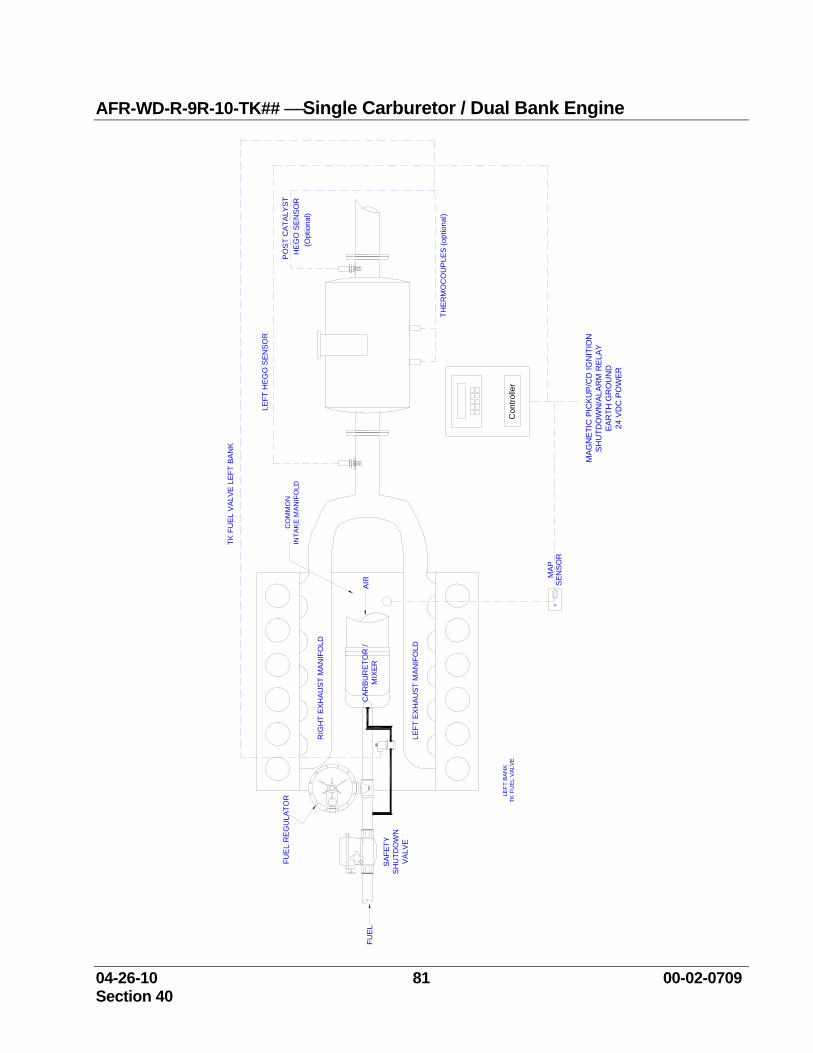
04-26-10 81 00-02-0709 Section 40
AFR-WD-R-9R-10-TK## ⎯Single Carburetor / Dual Bank Engine
FUE
L R
EG
ULA
TOR
SH
UTD
OW
NS
AFE
TY
VA
LVE
TK F
UE
L V
ALV
E L
EFT
BAN
K
CA
RB
UR
ETO
R /
MIX
ER
LEFT
EX
HA
US
T M
AN
IFO
LD
RIG
HT
EX
HA
UST
MA
NIF
OLD
FUE
L
LEFT
HE
GO
SE
NS
OR
MAP
SEN
SOR
THE
RM
OC
OU
PLE
S (o
ptio
nal)
AIR
PO
ST
CA
TALY
ST
Con
trolle
r
MAG
NE
TIC
PIC
KU
P/C
D IG
NIT
ION
SH
UTD
OW
N/A
LAR
M R
ELA
YE
AR
TH G
RO
UN
D24
VD
C P
OW
ER
CO
MM
ON
INTA
KE
MAN
IFO
LDH
EG
O S
EN
SO
R
LEFT
BAN
KTK
FU
EL V
ALVE
(Opt
iona
l)
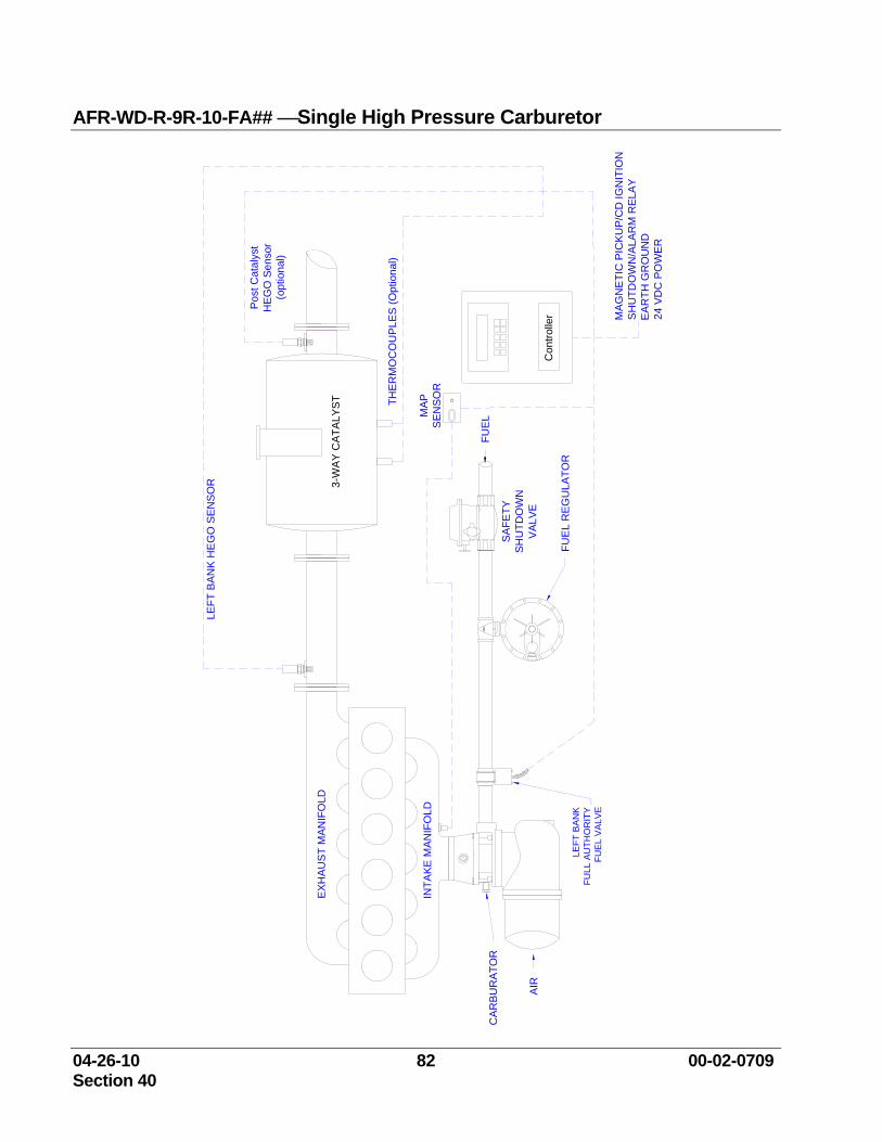
04-26-10 82 00-02-0709 Section 40
AFR-WD-R-9R-10-FA## ⎯Single High Pressure Carburetor
FUEL
CA
RB
UR
ATO
R
AIR
INTA
KE M
ANIF
OLD
EX
HA
UST
MAN
IFO
LD
SHU
TDO
WN
SA
FETY
VAL
VEC
ontro
ller
FUE
L R
EG
ULA
TOR
THE
RM
OC
OU
PLES
(Opt
iona
l)
LEFT
BA
NK
HE
GO
SEN
SOR 3-
WAY
CAT
ALY
ST
MA
GN
ETI
C P
ICKU
P/C
D IG
NIT
ION
SH
UTD
OW
N/A
LAR
M R
ELAY
EA
RTH
GR
OU
ND
24 V
DC
PO
WER
MAP
SEN
SOR
Pos
t Cat
alys
tH
EGO
Sen
sor
(opt
iona
l)
LEFT
BA
NK
FULL
AU
THO
RIT
Y
FUE
L V
ALV
E
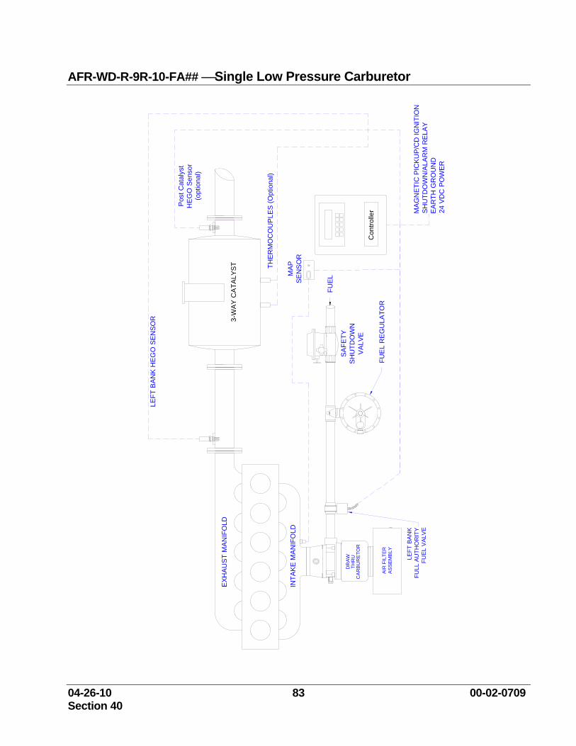
04-26-10 83 00-02-0709 Section 40
AFR-WD-R-9R-10-FA## ⎯Single Low Pressure Carburetor
FUEL
INTA
KE
MA
NIF
OLD
EXH
AU
ST M
AN
IFO
LD
SH
UTD
OW
NS
AFE
TY
VA
LVE
Con
trolle
rFU
EL
RE
GU
LATO
R
THE
RM
OC
OU
PLE
S (O
ptio
nal)
LEFT
BA
NK
HE
GO
SEN
SOR 3-
WAY
CA
TALY
ST
MA
GN
ETIC
PIC
KU
P/C
D IG
NIT
ION
SH
UTD
OW
N/A
LAR
M R
ELAY
EA
RTH
GR
OU
ND
24 V
DC
PO
WER
MAP
SEN
SO
R
Pos
t Cat
alys
tH
EG
O S
enso
r(o
ptio
nal)
CA
RB
UR
ETO
R
AIR
FIL
TER
ASS
EM
BLY
THR
UD
RA
W LEFT
BA
NK
FULL
AU
THO
RIT
Y
FUE
L V
ALV
E
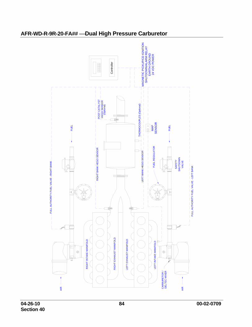
04-26-10 84 00-02-0709 Section 40
AFR-WD-R-9R-20-FA## ⎯Dual High Pressure Carburetor
FUE
L R
EG
ULA
TOR
SH
UTD
OW
NS
AFE
TY
VA
LVE
CAR
BUR
ETO
R /
DEL
TEC
MIX
ER
AIR
LEFT
EX
HA
US
T M
ANIF
OLD
LEFT
INTA
KE
MA
NIF
OLD
RIG
HT
EX
HA
US
T M
ANIF
OLD
RIG
HT
INTA
KE
MAN
IFO
LD
AIR
FUEL
FUEL
THE
RM
OC
OU
PLES
(Opt
iona
l)
HEG
O S
EN
SOR
POS
T C
ATA
LYST
RIG
HT
BA
NK
HEG
O S
ENSO
R
FULL
AU
THO
RIT
Y F
UEL
VAL
VE -
RIG
HT
BAN
K
LEFT
BA
NK
HEG
O S
ENSO
R
FULL
AU
THO
RIT
Y F
UE
L VA
LVE
- LE
FT B
ANK
Con
trolle
r
(Opt
iona
l)
MAP
SEN
SOR
MAG
NE
TIC
PIC
KUP
/CD
IGN
ITIO
NS
HU
TDO
WN
/ALA
RM
REL
AYE
AR
TH G
RO
UN
D24
VD
C P
OW
ER

04-26-10 85 00-02-0709 Section 40
AFR-WD-R-9R-20-FA## ⎯Dual Carburetor / Common Exhaust Manifold
FUE
L R
EG
ULA
TOR
SH
UTD
OW
NS
AFE
TY
VAL
VE
CA
RB
UR
ETO
R /
DE
LTE
C M
IXER
AIR
CO
MM
ON
EX
HA
US
T M
AN
IFO
LD
LEFT
INTA
KE
MA
NIF
OLD
RIG
HT
INTA
KE
MA
NIF
OLD
AIR
FUE
L
FUE
L
THE
RM
OC
OU
PLE
S (O
ptio
nal)
HE
GO
SE
NS
OR
PO
ST
CA
TALY
ST
FULL
AU
THO
RIT
Y F
UE
L VA
LVE
- LE
FT B
AN
K
LEFT
BA
NK
HEG
O S
EN
SOR
FULL
AU
THO
RIT
Y F
UE
L V
ALV
E - L
EFT
BAN
K
Con
trolle
r
(Opt
iona
l)
MA
PS
EN
SO
R
MAG
NE
TIC
PIC
KU
P/C
D IG
NIT
ION
SH
UTD
OW
N/A
LAR
M R
ELA
YE
ARTH
GR
OU
ND
24 V
DC
PO
WE
R
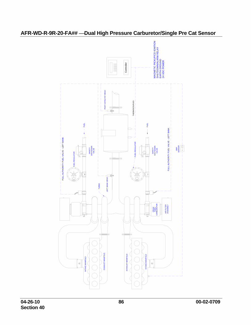
04-26-10 86 00-02-0709 Section 40
AFR-WD-R-9R-20-FA## ⎯Dual High Pressure Carburetor/Single Pre Cat Sensor
LEFT
BA
NK
HEG
O
MA
PS
EN
SOR
INTA
KE
MAN
IFO
LD
AIR
FIL
TER
AS
SE
MBL
Y
CA
RB
UR
ETO
R
DR
AWTH
RU
EX
HA
UST
MA
NIF
OLD
TUR
BO
FUE
L R
EG
ULA
TOR
FUEL
FUE
L R
EG
ULA
TOR
VA
LVE
SAF
ETY
SH
UTD
OW
N
THE
RM
OC
OU
PLE
S
FUEL
SAF
ETY
SH
UTD
OW
NV
ALV
E
POS
T C
ATA
LYS
T H
EGO
Con
trolle
r
MAG
NE
TIC
PIC
KUP
/CD
IGN
ITIO
NS
HU
TDO
WN
/ALA
RM
RE
LAY
EA
RTH
GR
OU
ND
24 V
DC
PO
WER
EXH
AU
ST
MAN
IFO
LD
INTA
KE
MAN
IFO
LD
FULL
AU
THO
RIT
Y F
UEL
VAL
VE -
LEFT
BAN
K
FULL
AU
THO
RIT
Y FU
EL
VAL
VE -
LEFT
BAN
K
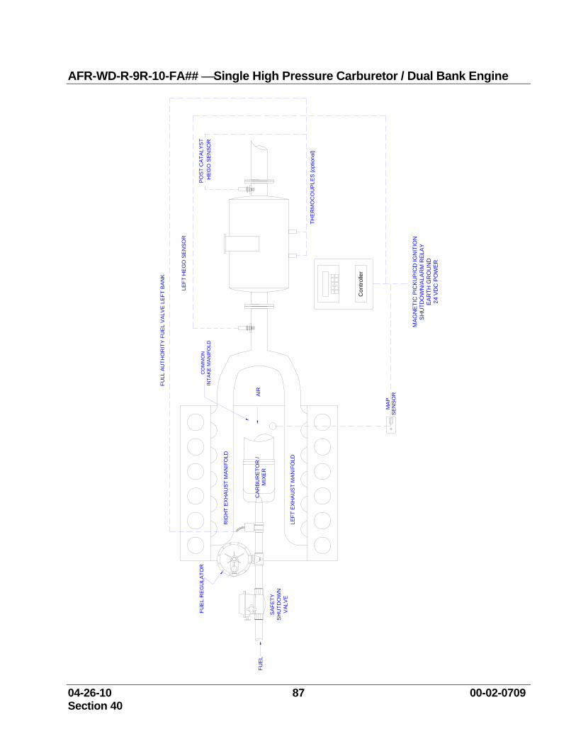
04-26-10 87 00-02-0709 Section 40
AFR-WD-R-9R-10-FA## ⎯Single High Pressure Carburetor / Dual Bank Engine
FUE
L R
EG
ULA
TOR
SH
UTD
OW
NS
AFE
TY
VAL
VE
FULL
AU
THO
RIT
Y FU
EL
VAL
VE
LE
FT B
AN
K
CA
RBU
RE
TOR
/ M
IXE
R
LEFT
EX
HA
US
T M
AN
IFO
LD
RIG
HT
EX
HAU
ST
MAN
IFO
LD
FUE
L
LEFT
HE
GO
SEN
SO
R
MA
PS
ENS
OR
THE
RM
OC
OU
PLE
S (o
ptio
nal)
AIR
PO
ST C
ATA
LYS
T
Con
trolle
r
MAG
NE
TIC
PIC
KU
P/C
D IG
NIT
ION
SH
UTD
OW
N/A
LAR
M R
ELA
YE
AR
TH G
RO
UN
D24
VD
C P
OW
ER
CO
MM
ON
INTA
KE
MA
NIF
OLD
HE
GO
SEN
SOR
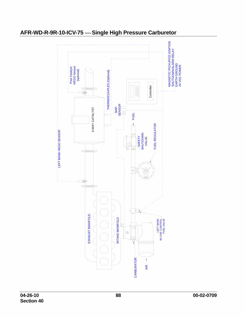
04-26-10 88 00-02-0709 Section 40
AFR-WD-R-9R-10-ICV-75 ⎯ Single High Pressure Carburetor
MAP
SE
NSO
R
FUEL
CAR
BUR
ATO
R
AIR
INTA
KE
MA
NIF
OLD
EXH
AUST
MAN
IFO
LD
SH
UTD
OW
NS
AFET
Y
VAL
VEC
ontro
ller
FUE
L R
EGU
LATO
R
THER
MO
CO
UPL
ES
(Opt
iona
l)
LEFT
BA
NK
HEG
O S
ENSO
R 3-W
AY C
ATA
LYST
MA
GN
ETIC
PIC
KUP/
CD
IGN
ITIO
NSH
UTD
OW
N/A
LAR
M R
ELA
YE
ARTH
GR
OU
ND
24 V
DC
PO
WER
Pos
t Cat
alys
tH
EGO
Sen
sor
(opt
iona
l)
LEFT
BA
NK
IN-L
INE
CO
NTR
OL
FUE
L V
ALV
E
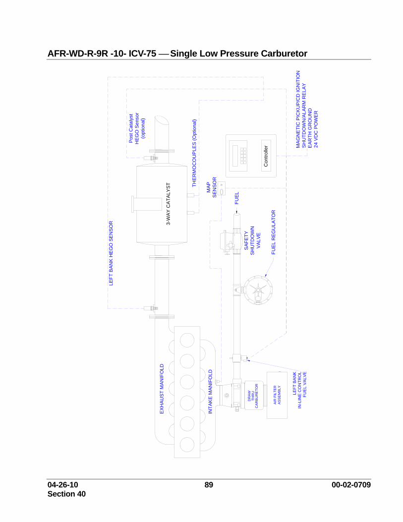
04-26-10 89 00-02-0709 Section 40
AFR-WD-R-9R -10- ICV-75 ⎯ Single Low Pressure Carburetor
FUEL
INTA
KE
MA
NIF
OLD
EXH
AUST
MAN
IFO
LD
SH
UTD
OW
NS
AFET
Y
VA
LVE
Con
trolle
rFU
EL
RE
GU
LATO
R
THE
RM
OC
OU
PLE
S (O
ptio
nal)
LEFT
BA
NK
HE
GO
SEN
SOR 3-
WAY
CA
TALY
ST
MA
GN
ETI
C P
ICK
UP/
CD
IGN
ITIO
NS
HU
TDO
WN
/ALA
RM
RE
LAY
EAR
TH G
RO
UN
D24
VD
C P
OW
ER
Pos
t Cat
alys
tH
EG
O S
enso
r(o
ptio
nal)
CA
RB
UR
ETO
R
AIR
FIL
TER
AS
SE
MBL
Y
THR
UD
RA
W LEFT
BA
NK
IN-L
INE
CO
NTR
OL
FUE
L VA
LVE
MAP
SE
NSO
R
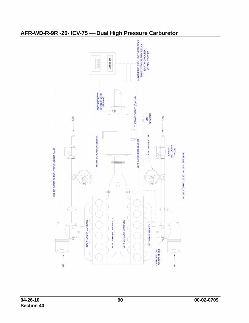
04-26-10 90 00-02-0709 Section 40
AFR-WD-R-9R -20- ICV-75 ⎯ Dual High Pressure Carburetor
FUE
L R
EG
ULA
TOR
SH
UTD
OW
NS
AFE
TY
VA
LVE
CA
RB
UR
ETO
R /
DEL
TEC
MIX
ER
AIR
LEFT
EX
HA
US
T M
AN
IFO
LD
LEFT
INTA
KE
MA
NIF
OLD
RIG
HT
EX
HA
UST
MA
NIF
OLD
RIG
HT
INTA
KE
MA
NIF
OLD
AIR
FUE
L
FUE
L
THE
RM
OC
OU
PLES
(Opt
iona
l)
HE
GO
SE
NSO
RP
OS
T C
ATA
LYST
RIG
HT
BA
NK
HEG
O S
EN
SOR
IN-L
INE
CO
NTR
OL
FUE
L VA
LVE
- R
IGH
T B
ANK
LEFT
BA
NK
HE
GO
SE
NS
OR
IN-L
INE
CO
NTR
OL
FUE
L VA
LVE
- LE
FT B
AN
K
Con
trolle
r
(Opt
iona
l)
MA
GN
ETI
C P
ICK
UP/
CD
IGN
ITIO
NS
HU
TDO
WN
/ALA
RM
RE
LAY
EA
RTH
GR
OU
ND
24 V
DC
PO
WER
MA
PS
EN
SOR
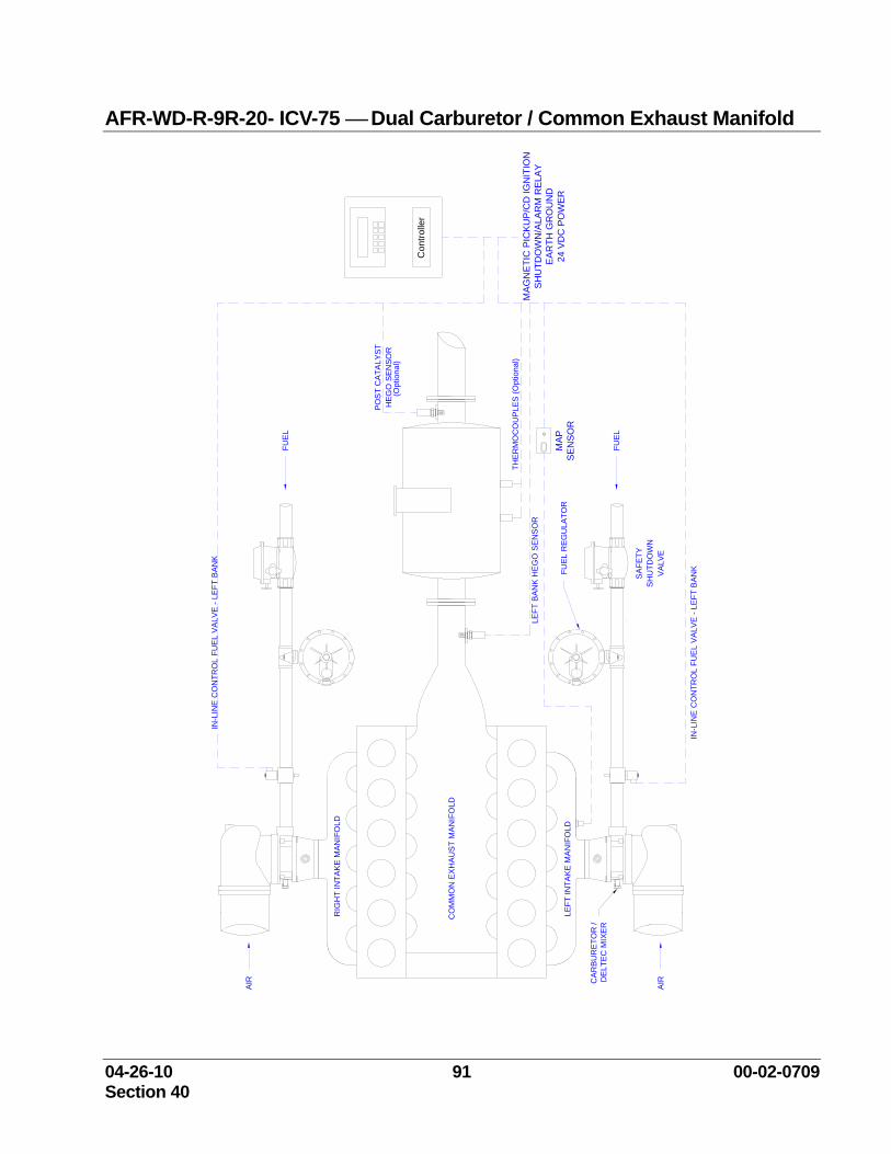
04-26-10 91 00-02-0709 Section 40
AFR-WD-R-9R-20- ICV-75 ⎯ Dual Carburetor / Common Exhaust Manifold
FUE
L R
EG
ULA
TOR
SH
UTD
OW
NS
AFE
TY
VAL
VE
CA
RB
UR
ETO
R /
DE
LTE
C M
IXE
R
AIR
CO
MM
ON
EX
HA
US
T M
AN
IFO
LD
LEFT
INTA
KE
MA
NIF
OLD
RIG
HT
INTA
KE
MA
NIF
OLD
AIR
FUEL
FUEL
THE
RM
OC
OU
PLE
S (O
ptio
nal)
HE
GO
SEN
SOR
PO
ST
CA
TALY
ST
IN-L
INE
CO
NTR
OL
FUE
L V
ALV
E - L
EFT
BAN
K
LEFT
BA
NK
HE
GO
SE
NS
OR
IN-L
INE
CO
NTR
OL
FUE
L V
ALV
E - L
EFT
BAN
K
Con
trolle
r
(Opt
iona
l)
MA
GN
ETIC
PIC
KU
P/C
D IG
NIT
ION
SHU
TDO
WN
/ALA
RM
REL
AYE
ARTH
GR
OU
ND
24 V
DC
PO
WER
MAP
SEN
SOR
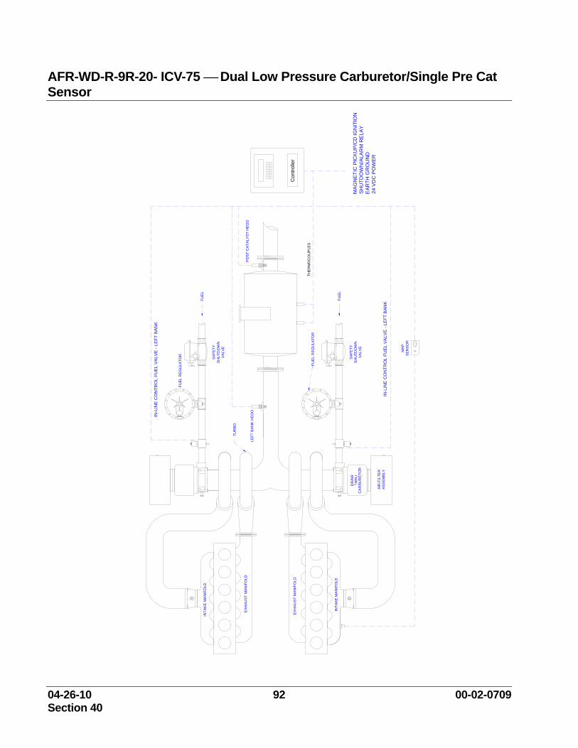
04-26-10 92 00-02-0709 Section 40
AFR-WD-R-9R-20- ICV-75 ⎯ Dual Low Pressure Carburetor/Single Pre Cat Sensor
LEFT
BA
NK
HE
GO
INTA
KE
MA
NIF
OLD
AIR
FIL
TER
ASS
EM
BLY
CAR
BU
RE
TOR
DR
AWTH
RU
EX
HA
US
T M
ANIF
OLD
TUR
BO
FUE
L R
EG
ULA
TOR
FUE
L
FUE
L R
EG
ULA
TOR
VALV
E
SA
FETY
SH
UTD
OW
N
THE
RM
OC
OU
PLE
S
FUE
L
SAF
ETY
SH
UTD
OW
NVA
LVE
PO
ST
CA
TALY
ST H
EGO
Con
trolle
r
MA
GN
ETIC
PIC
KU
P/C
D IG
NIT
ION
SH
UTD
OW
N/A
LAR
M R
ELA
YE
AR
TH G
RO
UN
D24
VD
C P
OW
ER
EXH
AUST
MA
NIF
OLD
INTA
KE
MA
NIF
OLD
IN-L
INE
CO
NTR
OL
FUEL
VA
LVE
- LEF
T BA
NK
IN-L
INE
CO
NTR
OL
FUEL
VA
LVE
- LEF
T BA
NK
MAP
SEN
SO
R
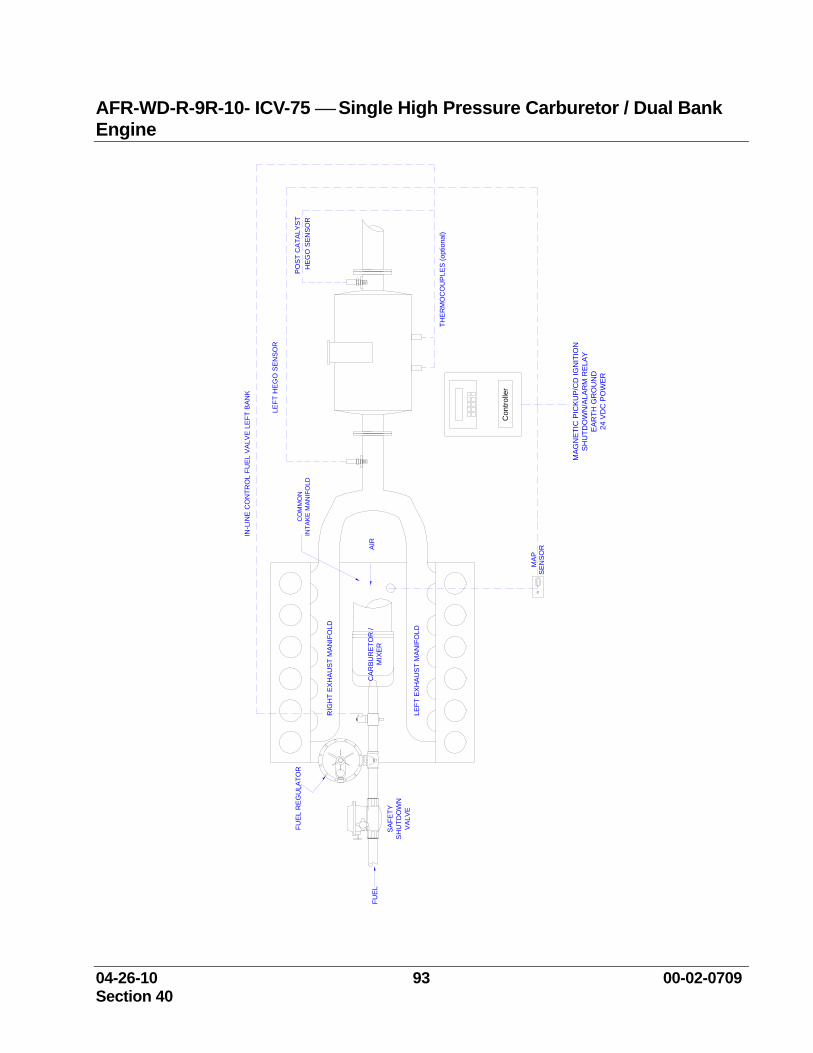
04-26-10 93 00-02-0709 Section 40
AFR-WD-R-9R-10- ICV-75 ⎯ Single High Pressure Carburetor / Dual Bank Engine
FUE
L R
EG
ULA
TOR
SH
UTD
OW
NS
AFE
TY
VAL
VE
IN-L
INE
CO
NTR
OL
FUE
L VA
LVE
LEFT
BAN
K
CAR
BUR
ETO
R /
MIX
ER
LEFT
EX
HA
US
T M
AN
IFO
LD
RIG
HT
EX
HA
US
T M
AN
IFO
LD
FUEL
LEFT
HE
GO
SE
NSO
R
THE
RM
OC
OU
PLE
S (o
ptio
nal)
AIR
PO
ST
CA
TALY
ST
Con
trolle
r
MA
GN
ETIC
PIC
KU
P/C
D IG
NIT
ION
SHU
TDO
WN
/ALA
RM
REL
AYE
AR
TH G
RO
UN
D24
VD
C P
OW
ER
CO
MM
ON
INTA
KE
MA
NIF
OLD
HE
GO
SEN
SOR
MA
PS
EN
SOR

04-26-10 94 00-02-0709 Section 40
04-26-10 95 00-02-0709 Section 40
This manual is the sole property of FW Murphy and Compliance Controls. Copying, faxing, e-mailing, altering or in any way reproducing this manual in whole or in part is forbidden without the express written consent of FW Murphy and Compliance Controls. FW Murphy and Compliance Controls reserves the right to change or alter any and all specifications at anytime without prior notification and without incurring any obligation to such changes. The information included in this publication is believed to be accurate at the time of publication; however, no responsibility is taken by FW Murphy and Compliance Controls unless expressly given.