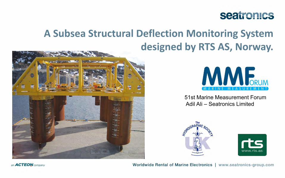
A Subsea Structural Deflection Monitoring System
designed by RTS AS, Norway.
51st Marine Measurement Forum Adil Ali – Seatronics Limited

Seatronics and RTS • Seatronics Limited : Established: 1978, Aberdeen-based
Marine Technology Specialists with an overseas presence in 5 continents.
• Core business is equipment rental ( sectors incl. positioning, geophysical, subsea construction, hydrography, Metocean, ROV tooling).
• RTS AS - technology partners based in Norway. • Innovation, integration and installation. • Technical liaison with construction companies (e.g. Subsea7,
Tecnip, Saipem etc.) using existing technology for specialist monitoring and subsea structural measurement and assessment.

Why monitor subsea structures ? • Larger template structures – heavy (100’s to few 1000’s
tons, sizes between 20-60m) . Balance between strength and weight. Avoid over-engineering . Cost !
• Reduced risk and time. Standard procedure in Norwegian Sector.
• Structures flex on lowering to seafloor, both through water column and on seabed settling using suction piles.
• Keep any flexing within the engineered tolerances. • Lifespan between 10 and 40 years on seabed, ensures
structural integrity.

Why SDM ?
• Problem:
• Lightweight structures with a tendency to twist during deployment • Deflection needs to be monitored with set limits dictating inspection
regime following installation. (more flexing = more rigorous inspection regime throughout structure lifespan).
• Client Specification:
• Design, supply & support a “Subsea Deflection Monitoring” (SDM) package to provide:-
• High accuracy heading, pitch, and roll • Four high precision depth sensors simultaneously polled • Acoustic modem link to surface • Subsea data logger for post install reply and analysis

Structures – manifolds, riser bases, PLEMS, templates

Principles of Operation
• POSITION of Structure is determined by Compatts, LBL array , beacons. (e.g. Kongsberg MPTs)
• HEADING is determined by Gyro compass installation structure (Fibro Option Gyro, e.g. Ixblue ROVINS or Octans
• DEPTH is determined by use of pressure sensors or digiquartz sensors at each corner.
• Powered by internal batteries and data transmitted acoustically to modem on an ROV, with Hotstab comms as back-up.
• Data displayed , stored and monitored on main installation vessel.

Equipment • Seatronics/RTS - SDM packages each comprise
• iXBlue Octans FOG • Four 700m Paroscientific Digiquartz pressure sensors (Accuracy +/-0.005% FS 0.0001% Resolution) • Dual underwater CDL Mini Txt displays (H and P & R) • Benthos LF Modem – data transmittal. • DeepSea Power & Light Batteries (48hrs ops) • Subsea Data Logger (16Gb) with time stamping of data • Log file dumping via Ethernet • Back-up system, 100% redundancy • Inclinometers
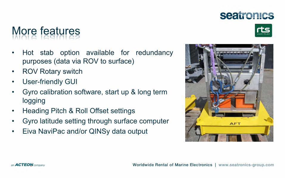
More features
• Hot stab option available for redundancy purposes (data via ROV to surface)
• ROV Rotary switch • User-friendly GUI • Gyro calibration software, start up & long term
logging • Heading Pitch & Roll Offset settings • Gyro latitude setting through surface computer • Eiva NaviPac and/or QINSy data output

Survey equipment Digiquartz depth sensors (Z)
MPT beacon (x,y)
SDM Gyro packs incl. subsea batteries, subsea displays. (heading)

Gyro display and position on structure…
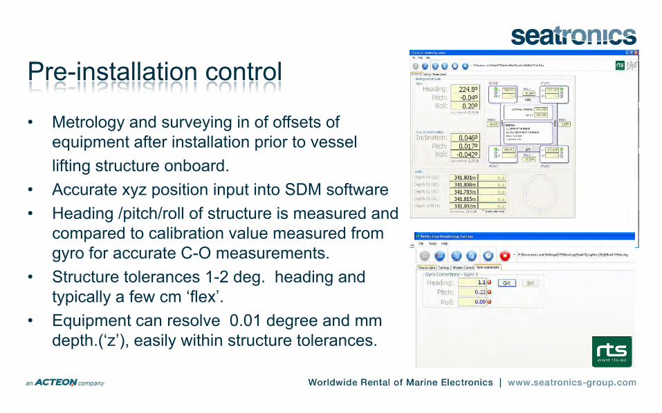
Pre-installation control
• Metrology and surveying in of offsets of equipment after installation prior to vessel
lifting structure onboard. • Accurate xyz position input into SDM software • Heading /pitch/roll of structure is measured and
compared to calibration value measured from gyro for accurate C-O measurements.
• Structure tolerances 1-2 deg. heading and typically a few cm ‘flex’.
• Equipment can resolve 0.01 degree and mm depth.(‘z’), easily within structure tolerances.

Display and monitoring
•All survey equipment surveyed in and interconnected/integrated. •Data presented real time in vessel lift control room for key personnel : Barge Captain project engineer, surveyor client rep., geologist, rep. from structure manufacturer, RTS technician •Data stored and logged in subsea logger , a at surface data can be sent via RS232 to survey package e.g. Qinsy, or Eiva NaviPac etc for post installation analysis.

Surface display and ROV view of the SDM display

Real-time deflection graphs
• Each corner graphically displayed
• Inclination, pitch and roll measured , logged and displayed.
SDM benefits, case study
• • 5 templates successfully installed in 320m of water • • 4 of the templates were 380 tonnes each 25 x 15 x 16m • Client estimated that the project would take 25 days • Project completed in 18 days • This allowed for 36 hours crane breakdown and 48 hours weather • SDM has been used on the Tyrihans and Norne projects for Acergy,
Skarv for SS7 and most recently the Sequoia project for Saipem.

Finally…
• Deliverables to client are screen shots, log file, and a safe, deflection- free installation of an
extremely large and heavy structure. • Future development - laser scanned structures can
be represented 3D data files, giving a full 3D graphical representation of the structure being lowered through the water column and being sucked down onto the seabed ?
• Real time feedback from SDM software to crane or suction piles to speed up, stop or slow down the lowering process ? Depends on individual strops and blocks for each corner.