dot/faa/tc-16/57 commercial off-the-shelf …. report no. dot/faa/tc-16/57 2. government accession...
TRANSCRIPT

DOT/FAA/TC-16/57 Federal Aviation Administration William J. Hughes Technical Center Aviation Research Division Atlantic City International Airport New Jersey 08405
Commercial Off-The-Shelf Airborne Electronic Hardware Issues and Emerging Solutions: Authority for Expenditure No. 75 Report September 2017 Final Report This document is available to the U.S. public through the National Technical Information Services (NTIS), Springfield, Virginia 22161. This document is also available from the Federal Aviation Administration William J. Hughes Technical Center at actlibrary.tc.faa.gov.
U.S. Department of Transportation Federal Aviation Administration

NOTICE
This document is disseminated under the sponsorship of the U.S. Department of Transportation in the interest of information exchange. The U.S. Government assumes no liability for the contents or use thereof. The U.S. Government does not endorse products or manufacturers. Trade or manufacturers’ names appear herein solely because they are considered essential to the objective of this report. The findings and conclusions in this report are those of the author(s) and do not necessarily represent the views of the funding agency. This document does not constitute FAA policy. Consult the FAA sponsoring organization listed on the Technical Documentation page as to its use. This report is available at the Federal Aviation Administration William J. Hughes Technical Center’s Full-Text Technical Reports page: actlibrary.tc.faa.gov in Adobe Acrobat portable document format (PDF).

Technical Report Documentation Page 1. Report No. DOT/FAA/TC-16/57
2. Government Accession No. 3. Recipient's Catalog No.
4. Title and Subtitle COMMERCIAL OFF-THE-SHELF AIRBORNE ELECTRONIC HARDWARE ISSUES AND EMERGING SOLUTIONS: AUTHORIZATION FOR EXPENDITURE NO. 75
5. Report Date September 2017 6. Performing Organization Code
7. Author(s) Condra, Lloyd1, Horan, Gary2, Forsberg, Håkan3, Matthews, Dave4, Peterson, James5, Martin, Avelino6, Barbagelata, Serge6, Lillestolen, Kirk7, Redman, Dave8, Petre, Brian9, Kilgore, Charles10, Strasburger, John11, Manners, Robert12, and Gregory, Bob13
8. Performing Organization Report No.
9. Performing Organization Name and Address 1Boeing PO Box 3707 Seattle, WA 98124-2207
2Federal Aviation Administration E&PD Standards Staff, Engine Controls Burlington, MA 01803
3Saab SE-58188 Linkoping Sweden
4Rockwell Collins 400 Collins Road NE Cedar Rapids, IA 52498
5Honeywell Aerospace 9201 San Mateo Blvd, NE, MS C01 Albuquerque, NM 87113
6Airbus Group 12 Rue Pasteur, BP76 92150 Suresnes France
7UTC Aerospace Systems 1 Hamilton Road Windsor Locks, CT 06096
8Texas A&M Engineering Experiment Station 3126 TAMU College Station, TX 77843-3126
9GE Aviation Systems 3290 Patterson Ave, SE Grand Rapids, MI 49512
10Federal Aviation Administration Software and Electronics Section Atlantic City Int’l. Airport, NJ 08405
11Federal Aviation Administration Systems Integration Section Fort Worth, TX 76137
12Hi-Tec Systems, Inc. (FAA contractor) 6727 Delilah Road Egg Harbor Township, NJ 08234
13Rolls-Royce plc P.O. Box 2000, Raynesway, Derby, DE21 7XX England
10. Work Unit No. (TRAIS)
11. Contract or Grant No.
12. Sponsoring Agency Name and Address U.S. Department of Transportation, Federal Aviation Administration Aircraft Certification Service—Design, Manufacturing, and Airworthiness FAA National Headquarters 950 L’Enfant Plaza, S.W., Washington, D.C. 20024
13. Type of Report and Period Covered Final Report 14. Sponsoring Agency Code AIR-134
15. Supplementary Notes The FAA William J. Hughes Technical Center Aviation Research Division COR was Charles Kilgore. 16. Abstract This report, based on global industry and regulatory expert experience and knowledge, illustrates only the top level of elemental aspects regarding commercial off-the-shelf (COTS) components embedded in airborne electronic hardware (AEH) issues and provides possibilities for COTS AEH solutions development including: 1) the use of existing standards and guidance documents as a structure for future evolution of COTS standards, 2) possible future COTS standards to implement this structure, 3) the need for combined industry/regulatory/manufacturing research to develop COTS AEH issues mitigations, including the development of COTS standards and guidance, 4) mechanisms to shorten the slow evolution of standards, 5) a candidate structure for relevant and emerging COTS standards linked to evolving development assurance standards, and 6) the identification of standard bodies responsible for the implementation of the ongoing COTS solution(s). This report provides a COTS AEH assurance framework, including a common structured approach to evaluate COTS AEH issues. This approach is applied to the 22 issues addressed in the report and is recommended for application to future issues not addressed herein. The approach is presented in a manner that supports development of project-level COTS AEH mitigations that can be rolled into development, design assurance, and a practical compliance solution for FAA engineers, delegates, and standards administrators. There is a stand-alone treatment of each issue and a five-step suggested evolution of COTS and development assurance standards and guidelines. The research (1) includes detailed technical information about the issues, (2) introduces research required to provide new knowledge needed to implement solutions for the COTS AEH issues, (3) explores required tools, standards, and guidance needed for COTS-based systems development assurance, certification, and maintenance, and (4) considers certification-process and assessment criteria as well as methods for the given issues. The approach may be used to evaluate and develop emerging COTS AEH issues. This report also addresses design, component selection, development assurance, and certification-process issues for AEH COTS electronics product items, such as hybrids, multichip modules, microprocessors, field-programmable gate arrays, application-specific integrated circuits, and small assemblies including printed wiring assemblies and disk drives. All organizations and individuals who work with COTS AEH in avionics are encouraged to read and understand this report — and those who address these COTS AEH issues should use the AFE 75 research approach and results described. 17. Key Words Commercial off-the-shelf, COTS, Airborne electronic hardware, Avionics, Aircraft certification, Regulatory standards and guidance, System qualification, Avionics safety, Hybrids, Multichip modules, Microprocessors, Field programmable gate arrays, Application-specific integrated circuits, COTS assemblies, Derating, Uprating, Sparing reliability, Complementary metal-oxide semiconductor, Single event effects, Atmospheric radiation, Limited-life semiconductors, Reliability, Lead-free electronics, Errata, Counterfeit parts, Undocumented features, Usage, Production, Unknown changes, Embedded controllers, Packaging and mounting, Obsolescence management, Compliance, Design assurance, System on chip
18. Distribution Statement This document is available to the U.S. public through the National Technical Information Service (NTIS), Springfield, Virginia 22161. This document is also available from the FAA William J. Hughes Technical Center at actlibrary.tc.faa.gov.
19. Security Classif. (of this report) Unclassified
20. Security Classif. (of this page) Unclassified
21. No. of Pages 152
22. Price
Form DOT F 1700.7 (8-72) Reproduction of completed page authorized

iii
ACKNOWLEDGEMENTS
The project management committee (PMC) chairman for this commercial off-the-shelf airborne electronic hardware assurance project, Brian Petre, would like to thank the following people for their direct contributions to the research detailed in this report and persistent efforts throughout the course of this project: Serge Barbagelata, Airbus Group Andrew Berner, BAE Systems Lloyd Condra, The Boeing Company Chris Eckert, GE Aviation Håkan Forsberg, SAAB Bob Gregory, Rolls Royce Dan Higgins, BF Goodrich Gary Horan, FAA Charles Kilgore, FAA Kirk Lillestolen, UTC Bob Manners, Hi-Tec Systems, FAA contractor Avelino Martin, Airbus Group Dave Mathews, Rockwell Collins James Peterson, Honeywell William Scofield, Boeing Ingemar Söderquist, SAAB John Strasburger, FAA The PMC chairman would also like to acknowledge the following individuals and organizations for providing support to the project: Bob Chobot, BAE Systems Chantel Gil, Airbus Group/Eurocopter Barbara Lingberg, FAA Dave Redman, AVSI Director Jordan Smith, Texas A&M University

iv
TABLE OF CONTENTS
EXECUTIVE SUMMARY xvii
1. INTRODUCTION 1
1.1 Principles 1 1.2 Scope 2 1.3 AFE 75 Project Structure 2 1.4 Document Structure 3 1.5 COTS AEH Assurance Objective 4 1.6 COTS AEH Issues 4
2. ISSUE DEFINITIONS AND RECOMMENDATIONS 5
2.1 COTS Assemblies 6
2.1.1 Description of the Issue 6 2.1.2 Relationship to Safety and Certification 7 2.1.3 Existing Activity 7 2.1.4 Technology Weakness/Deficiency 8 2.1.5 Process Weakness/Deficiency 8 2.1.6 Recommendations/Desired Outcome 8 2.1.7 References 9 2.1.8 Acronyms 10
2.2 Derating 10
2.2.1 Description of the Issue 10 2.2.2 Relationship to Safety and Certification 10 2.2.3 Existing Activity 11 2.2.4 Technology Weakness/Deficiency 11 2.2.5 Process Weakness/Deficiency 12 2.2.6 Recommendation/Desired Outcome 12 2.2.7 References 14 2.2.8 Abbreviations and Acronyms 14
2.3 Sparing Reliability 16
2.3.1 Description of the Issue 16 2.3.2 Relationship to Safety and Certification 16 2.3.3 Existing Activity 17 2.3.4 Technology Weakness/Deficiency 18 2.3.5 Process Weakness/Deficiency 18 2.3.6 Recommendation/Desired Outcome 18 2.3.7 References 19 2.3.8 Acronyms 19

v
2.4 Commodity Memory 20
2.4.1 Description of the Issue 20 2.4.2 Relationship to Safety and Certification 20 2.4.3 Existing Activity 20 2.4.4 Technology Weakness/Deficiency 21 2.4.5 Process Weakness/Deficiency 21 2.4.6 Recommendation/Desired Outcome 21 2.4.7 References 22 2.4.8 Acronyms 22
2.5 Increased Susceptibility to Atmospheric Radiation 23
2.5.1 Description of the Issue 23 2.5.2 Relationship to Safety and Certification 23 2.5.3 Existing Activity 23 2.5.4 Technology Weakness/Deficiency 24 2.5.5 Process Weakness/Deficiency 26 2.5.6 Recommendation/Desired Outcome 29 2.5.7 References 31 2.5.8 Acronyms and Abbreviations 32
2.6 Limited-life Semiconductors Issue Overview 34
2.6.1 Limited-Life Semiconductors Issue Details 34 2.6.2 Relationship to Safety and Certification 35 2.6.3 Existing Activity 36 2.6.4 Technology Weakness/Deficiency 36 2.6.5 Process Weakness/Deficiency 37 2.6.6 Recommendations/Desired Outcome 37 2.6.7 References 37 2.6.8 Acronyms and Abbreviations 38
2.7 Outdated Reliability Assessment Methods 39
2.7.1 Description of the Issue 39 2.7.2 Relationship to Safety and Certification 40 2.7.3 Existing Activity 40 2.7.4 Technology Weakness/Deficiency 40 2.7.5 Process Weakness/Deficiency 41 2.7.6 Recommendations /Desired Outcome 41 2.7.7 References 42 2.7.8 Acronyms 43
2.8 Transition to Lead-free Electronics 44

vi
2.8.1 Description of the Issue 44 2.8.2 Relationship to Safety and Certification 45 2.8.3 Existing Activity 46 2.8.4 Technology Weakness/Deficiency 47 2.8.5 Process Weakness/Deficiency 48 2.8.6 Recommendations/Desired Outcome 48 2.8.7 References 48 2.8.8 Acronyms and Abbreviations 49
2.9 Availability and Updates of Errata 50
2.9.1 Description of the Issue 50 2.9.2 Relationship to Safety and Certification 50 2.9.3 Existing Activity 51 2.9.4 Technology Weakness/Deficiency 51 2.9.5 Process Weakness/Deficiency 51 2.9.6 Recommendations/Desired Outcome 51 2.9.7 References 52 2.9.8 Acronyms and Abbreviations 53
2.10 Counterfeit Electronic Parts 53
2.10.1 Counterfeit Parts Issue Details 53 2.10.2 Relationship to Safety and Certification 54 2.10.3 Existing Activity 54 2.10.4 Technology Weakness/Deficiency 55 2.10.5 Process Weakness/Deficiency 55 2.10.6 Recommendation/Desired Outcome 55 2.10.7 References 56 2.10.8 Abbreviations and Acronyms 56
2.11 Undocumented Features 57
2.11.1 Description of the issue 57 2.11.2 Relationship to Safety and Certification 57 2.11.3 Existing activity 57 2.11.4 Technology Weakness/Deficiency 58 2.11.5 Process Weakness/Deficiency 58 2.11.6 Recommendation/Desired Outcome 58 2.11.7 References 59 2.11.8 Acronyms 59
2.12 Multiple AND Global Electronic Supply Chains 60
2.12.1 Description of the Issue 60 2.12.2 Relationship to Safety and Certification 60

vii
2.12.3 Existing Activity 61 2.12.4 Technology Weakness/Deficiency 61 2.12.5 Process Weakness/Deficiency 61 2.12.6 Recommendation/Desired Outcome 61 2.12.7 References 62 2.12.8 Acronyms 62
2.13 Usage Domain Analysis 62
2.13.1 Description of the Issue 62 2.13.2 Relationship to Safety and Certification 62 2.13.3 Existing Activity 62 2.13.4 Technology Weakness/Deficiency 63 2.13.5 Process Weakness/Deficiency 63 2.13.6 Recommendation/Desired Outcome 64 2.13.7 References 66 2.13.8 Acronyms 66
2.14 Production Follow-up 67
2.14.1 Description of the Issue 67 2.14.2 Relationship to Safety and Certification 68 2.14.3 Existing Activity 68 2.14.4 Technology Weakness/Deficiency 68 2.14.5 Process Weakness/Deficiency 69 2.14.6 Recommendations/Desired Outcome 69 2.14.7 References 69 2.14.8 Abbreviations and Acronyms 70
2.15 Intellectual Property 71
2.15.1 Description of the Issue 71 2.15.2 Relationship to Safety and Certification 71 2.15.3 Existing Activity 71 2.15.4 Technology Weakness/Deficiency 72 2.15.5 Process Weakness/Deficiency 72 2.15.6 Recommendation/Desired Outcome 73 2.15.7 References 73 2.15.8 Acronyms 73
2.16 Unknown Changes 74
2.16.1 Description of the Issue 74 2.16.2 Relationship to Safety and Certification 74 2.16.3 Existing Activity 74 2.16.4 Technology Weakness/Deficiency 75

viii
2.16.5 Process Weakness/Deficiency 75 2.16.6 Recommendations/Desired Outcome 75 2.16.7 References 75 2.16.8 Acronyms 76
2.17 Embedded Controllers 76
2.17.1 Description of the Issue 76 2.17.2 Relationship to Safety and Certification 77 2.17.3 Existing Activity 78 2.17.4 Technology Weakness/Deficiency 78 2.17.5 Process Weakness/Deficiency 78 2.17.6 Recommendation/Desired Outcome 78 2.17.7 References 79 2.17.8 Acronyms 79
2.18 Technology and Component Maturity 80 2.19 Component Packaging and Mounting Reliability 80
2.19.1 Description of the Issue 80 2.19.2 Relationship to Safety and Certification 80 2.19.3 Existing Activity 80 2.19.4 Technology Weakness/Deficiency 81 2.19.5 Process Weakness/Deficiency 81 2.19.6 Recommendation/Desired Outcome 81 2.19.7 References 82 2.19.8 Abbreviations and Acronyms 82
2.20 Device Uprating 83
2.20.1 Description of the Issue 83 2.20.2 Relationship to Safety and Certification 83 2.20.3 Existing Activity 84 2.20.4 Technology Weakness/Deficiency 84 2.20.5 Process Weakness/Deficiency 84 2.20.6 Recommendation/Desired Outcome 85 2.20.7 References 86 2.20.8 Acronyms and Abbreviations 86
2.21 Additional FAA Handbook Considerations 87
2.21.1 Description of the Issue 87 2.21.2 Relationship to Safety and Certification 89 2.21.3 Existing Activity 89 2.21.4 Technology Weakness/Deficiency 89 2.21.5 Process Weakness/Deficiency 90

ix
2.21.6 Recommendation/Desired Outcome 90 2.21.7 References 92 2.21.8 The following acronyms were used in section 2.21. 93
2.22 Obsolescence Management 93
2.22.1 Description of the Issue 93 2.22.2 Relationship to Safety and Certification 94 2.22.3 Existing Activity 94 2.22.4 Technology Weakness/Deficiency 95 2.22.5 Process Weakness/Deficiency 95 2.22.6 Recommendations/Desired Outcome 96 2.22.7 References 96 2.22.8 Acronyms 96
2.23 Acceptable Level of Compliance Evidence 97 2.24 Multiple Supply Chains 97 2.25 Demonstration Methods for Safe Use of Complex Commercial off-the-Shelf
Equipment in Airborne Electronics Hardware 97 2.26 System On Chip Devices 98
2.26.1 Description of the Issue 98 2.26.2 Relationship to Safety and Certification 99 2.26.3 Existing Activity 99 2.26.4 Technology Weakness/Deficiency 100 2.26.5 Process Weakness/Deficiency 100 2.26.6 Recommendation/Desired Outcome 100 2.26.7 References 100 2.26.8 Acronyms 101
3. AFE 75 RESULTS AND CONCLUSIONS 101
APPENDICES A—COMPOSITE AFE 75 FINAL REPORT REFERENCES
B—CANDIDATE COMPREHENSIVE GUIDANCE DOCUMENT STRUCTURE
C—COTS ISSUES, PROBLEMS, SOLUTIONS OVERVIEW
D—ISSUES SIMILARITY CHART BY GROUPINGS
x
LIST OF FIGURES
Figure Page 1 Energy spectrum of atmospheric neutrons at 40,000 feet and 45 degrees latitude 25
2 As feature sizes become smaller, a larger range of atmospheric neutron energies can cause SEE 28
3 Semiconductor wearout mechanisms 35
4 Spectrum of devices with embedded controllers or processors 77
5 Example of a traditional compared with an SoC-based system 98
xi
LIST OF TABLES
Table Page 1 AFE 75 candidate issues – selected and not-selected 5
2 SEE types 27
3 Acceleration models 36
4 Standards and handbooks for lead-free transition 47
5 Evaluating errata document quality 52
6 Questions for complex COTS components without errata 52

xii
LIST OF SYMBOLS, ABBREVIATIONS, AND ACRONYMS nm Nanometers Pb Lead SnPb Tin-lead Tambient Ambient temperature Tcase Maximum (outer case) temperature a component can stand Tjunction Junction temperature AC Advisory Circular ADHP Aerospace, defense, and high performance AEH Airborne electronic hardware AFE Authority for Expenditure (for AVSI projects) AFE 17 Methods to Account for Accelerated Semiconductor Wearout R&D Project AFE 43 Selection and Evaluation of Microprocessors for Critical Airborne Systems
R&D Project AFE 70 Integrated Reliability Processes R&D Project AFE 71 Reliability Prediction Software R&D Project AFE 72 Mitigating Radiation Effects R&D Project AFE 80 Integrated Reliability R&D Project AFE 83 Semiconductor Reliability R&D Project AFO Overall acceleration factor AFT Temperature acceleration factor AFV Voltage acceleration factor AIA Aerospace Industries Association ALU Arithmetic logic unit AMC Avionics Maintenance Conference ANADEF ANAlyse de DEFaillance (French Association specializing in failure
analysis) AND AND logic operation ANSI American National Standards Institute APMC Avionics Process Management Committee AQEC Aerospace Qualified Electronic Components AR Aviation research ARP Aeronautical recommended practice AS Aerospace Standard ASD AeroSpace and Defense Industries Association of Europe ASIC Application-specific integrated circuit ASSP Application specific standard product ATC Air traffic control AVSI Aerospace Vehicle System Institute BIST Built-in-self-test C Centigrade CA California CAF Conductive anodic filament CALCE Center for Advance Life Cycle Engineering (University of Maryland) CAMP COTS assembly management plan

xiii
CEH Complex electronic hardware CM EASA certification memorandum CMOS Complementary-metal-oxide-semiconductor CNES Centre national d'études spatiales (National Centre for Space Studies) COTS Commercial off-the-shelf COTS AEH Airborne electronic hardware available as COTS components COTS in AEH COTS components embedded in AEH CPU Central processing unit CRC Cyclic redundancy code CRI Certification review item CTE Coefficient of thermal expansion D&R Design & reuse DDECS Design and diagnostics of electronic circuits and systems DED Double error detection DRAM DfR DfR Solutions DFT Design for test DMS Diminishing manufacturing sources DMSMS Diminishing manufacturing sources and material shortages DO Document DoD Department of Defense DOT Department of Transportation DRAM Dynamic random-access memory DSPO Defense Standardization Program Office EASA European Aviation Safety Agency EC European Council ECC Error correcting code ECMP Electronic components management plan ECSS European cooperation for space standardization ED EUROCAE document EDA Electronic design automation EDFAS Electronic Device Failure Analysis Society EEE Electrical, electronic, and electromechanical (parts used in space systems) EIA Electronic Industries Alliance EM Electromigration eMMC Embedded multimedia card EPC European passive component EPCIA European Passive Component Industry Association EU European Union EUROCAE European Organisation for Civil Aviation Equipment FADEC Full authority digital engine control FIDES Latin root of the French word “fiabilité”—“reliability” in English FMEA Failure modes and effect analysis FMECA Failure mode effects and criticality analysis FPGA Field-programmable gate array FR-4 Circuit board material grade designator FTA Fault tree analysis

xiv
GAMA General Aviation Manufacturer Association GAO Government Accountability Office GEIA Government Electronics and Information Technology Association GHz Gigahertz GPD Graceful performance degradation H.R. House Resolution HCI Hot carrier injection HMI Human machine interface I/O Input/output IBM International Business Machines IC Integrated circuit IEC International Electrotechnical Commission IEEE Institute of Electrical and Electronics Engineers IMAPS International Microelectronics Assembly and Packaging Society INST Instructions IP Intellectual property IPC Association Connecting Electronics Industries IRPS International Reliability Physics Symposium ISCA International Symposium on Computer Architecture, ISTFA International Symposium for Testing and Failure Analysis JEDEC Joint Electronic Device Engineering Council JEPP Joint Electronic Device(s) Engineering Council Publication JESD JEDEC standard JTAG Joint Test Action Group KNC Knights Corner LCD Liquid crystal display LEAP Lead-Free Electronics in Aerospace Project LRU Line replaceable unit MAC Media access control MBU Multiple bit upset MCFA MultiCore for Avionics (Industry Group) MeV Million-electron-volts MIC Many independent core MIL Military MMC Multimedia card (flash memory card) NAND Not AND, i.e. negation of logical “AND” NASA National Aeronautics and Space Administration NBTI Negative bias temperature instability NSEU Neutron single-event upset NSWC Naval Surface Warfare Center OCM Original component manufacturer OEM Original equipment manufacturer ORNL Oak Ridge National Laboratory OSCI Open SystemC Initiative PAS Publically available specifications PBTI Positive bias temperature instability

xv
PCB Printed circuit board PCIe Peripheral Component Interconnect Express PCN Product change notice PERM Pb-free electronics risk management PHY Physical layer PLD Programmable logic device PMC Project Management Committee ppm Parts per million Q Quality (of the ECSS Space Product Assurance Branch) R&D Research & development RAS Reliability, availability, serviceability RoHS Restriction of Hazardous Substances RNC Referential Normatif du CNES ROM Read-only memory RTCA RTCA, Inc. (Radio Technical Commission for Aeronautics) SCD Specification control drawing SD Secure data SEB Single event burnout SEC Single error correction SEE Single event effects SEFI Single event functional interrupt SEGR Single event gate rupture SEL Single event latchup SET Single event transient SEU Single event upset SIB Safety Information Bulletin SM Surface mount SMT Surface mount technology SoC System on chip SoCCER SoC from Civilian to Armament Re-use SOW Statement of Work SPE Synergistic processing element SPIRIT Structure for Packaging, Integrating and Re-using IP within Tool-flows SRAM Static random access memory sRIO Serial rapid input/output SW Software SWCEH Software and complex electronic hardware TB Technical Bulletin TC Technical Committee TDDB Time dependent dielectric breakdown TP Technical Publication TR Technical Report TS Technical Specification U.S. United States UAV Unmanned aerial vehicle USB Universal serial bus

xvi
UTE French standard V Volts V&V Verification and validation VHDL VHSIC hardware description language VME Virtual machine environment WCET Worst case execution time WG Working group
xvii
EXECUTIVE SUMMARY
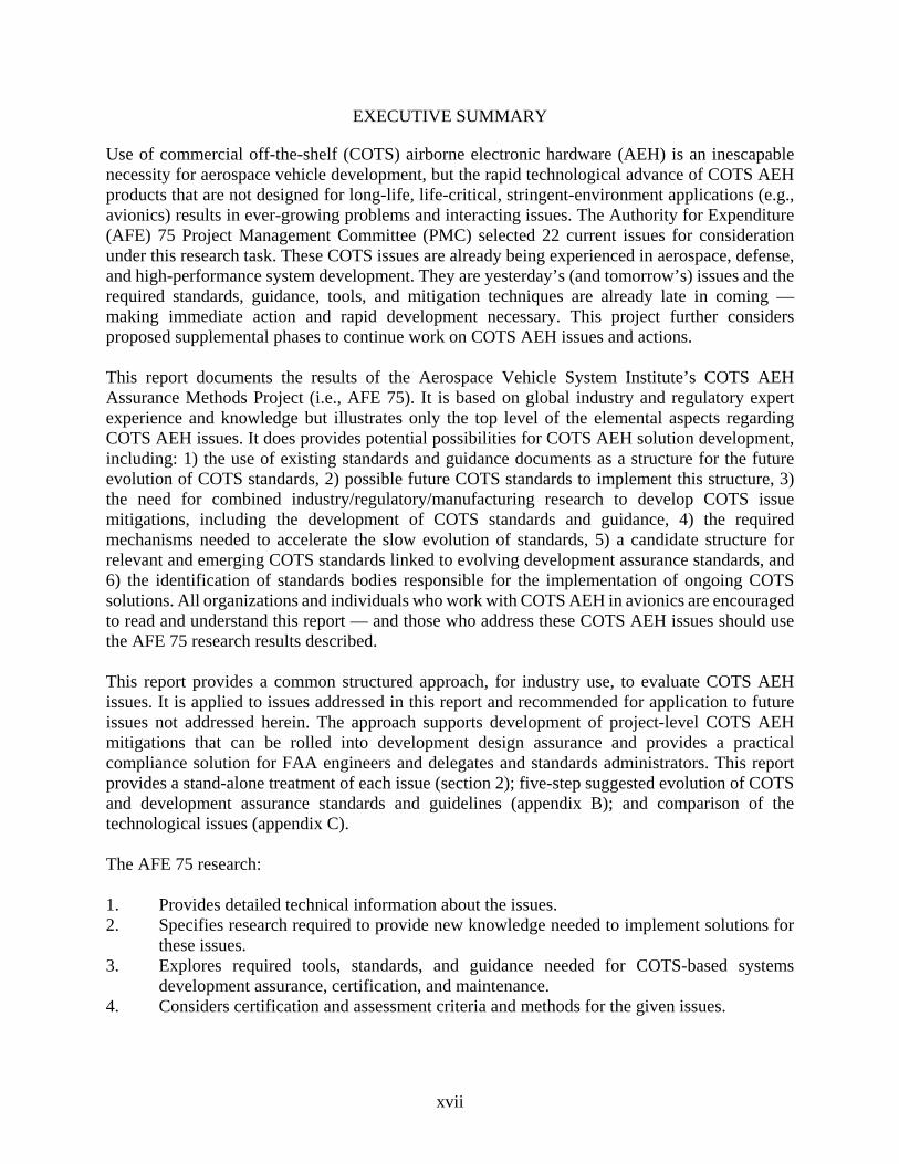
Use of commercial off-the-shelf (COTS) airborne electronic hardware (AEH) is an inescapable necessity for aerospace vehicle development, but the rapid technological advance of COTS AEH products that are not designed for long-life, life-critical, stringent-environment applications (e.g., avionics) results in ever-growing problems and interacting issues. The Authority for Expenditure (AFE) 75 Project Management Committee (PMC) selected 22 current issues for consideration under this research task. These COTS issues are already being experienced in aerospace, defense, and high-performance system development. They are yesterday’s (and tomorrow’s) issues and the required standards, guidance, tools, and mitigation techniques are already late in coming — making immediate action and rapid development necessary. This project further considers proposed supplemental phases to continue work on COTS AEH issues and actions. This report documents the results of the Aerospace Vehicle System Institute’s COTS AEH Assurance Methods Project (i.e., AFE 75). It is based on global industry and regulatory expert experience and knowledge but illustrates only the top level of the elemental aspects regarding COTS AEH issues. It does provides potential possibilities for COTS AEH solution development, including: 1) the use of existing standards and guidance documents as a structure for the future evolution of COTS standards, 2) possible future COTS standards to implement this structure, 3) the need for combined industry/regulatory/manufacturing research to develop COTS issue mitigations, including the development of COTS standards and guidance, 4) the required mechanisms needed to accelerate the slow evolution of standards, 5) a candidate structure for relevant and emerging COTS standards linked to evolving development assurance standards, and 6) the identification of standards bodies responsible for the implementation of ongoing COTS solutions. All organizations and individuals who work with COTS AEH in avionics are encouraged to read and understand this report — and those who address these COTS AEH issues should use the AFE 75 research results described. This report provides a common structured approach, for industry use, to evaluate COTS AEH issues. It is applied to issues addressed in this report and recommended for application to future issues not addressed herein. The approach supports development of project-level COTS AEH mitigations that can be rolled into development design assurance and provides a practical compliance solution for FAA engineers and delegates and standards administrators. This report provides a stand-alone treatment of each issue (section 2); five-step suggested evolution of COTS and development assurance standards and guidelines (appendix B); and comparison of the technological issues (appendix C). The AFE 75 research: 1. Provides detailed technical information about the issues. 2. Specifies research required to provide new knowledge needed to implement solutions for
these issues. 3. Explores required tools, standards, and guidance needed for COTS-based systems
development assurance, certification, and maintenance. 4. Considers certification and assessment criteria and methods for the given issues.

xviii
This structured approach is suitable for evaluating and developing solutions for emerging COTS AEH issues. This AFE 75 report addresses design, component selection, development assurance, and certification issues for AEH COTS and COTS in AEH electronics product items, such as hybrids, multichip modules, microprocessors, field-programmable gate arrays, application-specific integrated circuits, and small assemblies including printed wiring assemblies and disk drives. Of note, COTS electronics products are almost unanimously targeted for markets other than aerospace, and their designs, configuration-control processes, qualification methods, and reliability-assurance practices are developed and implemented without regard for the needs of aerospace users. The AFE 75 PMC subject-matter experts identified 26 categories of candidate issues unique to the incorporation of COTS electronics in aerospace systems design and selected 22 issues to be addressed in this research. Some candidate issues did not meet the AFE 75 criteria for COTS issues, and one — intellectual property — was beyond the resources available in this first AFE 75 phase. Each selected COTS issue was evaluated to determine their technical characteristics and impact on aerospace design, component selection, implementation, validation, certification, and life cycle maintenance. Special attention was given to the need for awareness of these issues by both industry and regulatory agencies to attain a level playing field based on consistent application of safety and reliability guidance and mitigation of the risks associated with the issues. Although both the commercial and military segments of the aerospace market are increasingly dependent on COTS, there is no consensus within the aerospace industry on methods to assure their safety and airworthiness in AEH or on criteria to verify that those methods are used properly in design, production, or support. A major characteristic of the COTS electronics market is the rapidity with which it changes and the regular emergence of new issues that can affect avionics safety and airworthiness. The COTS issues identified in this report are seen as a baseline set of issues. They may be modified as needed, and additional issues may be added in the future. This report explains how the issues can impact safety and airworthiness of aircraft and how they can be addressed in the certification process. To the extent possible, existing industry handbooks, standards, reports, and technical publications are leveraged in recommended design guidance document structure (appendix B) and in future work beyond the scope of AFE 75. Where additional knowledge is required, research to produce that knowledge and the candidate responsible organizations are identified. The nature of the COTS challenge is that the methods to demonstrate safe application of COTS AEH within the certification process are difficult, if not impossible, to define in any objective way. Furthermore, the methods that might be used are likely to be expensive and time consuming. A consensus is necessary within the aerospace industry and regulatory agencies regarding the methods, documents, and tools to be used in the development assurance and certification processes and the criteria and methods to verify compliance. The results of this report are designed to be actionable, including the detailed descriptions and recommendations for the 22 issues, the roadmap for the development of COTS AEH standards and guidelines, and the structured approach for the evaluation of COTS AEH issues. These results

xix
further offer a baseline for industry and regulatory action to achieve implemented solutions for current and future COTS AEH issues. Future system and aircraft development projects will need to address COTS AEH issues. Some of these COTS issues will be beyond the resources of a single project or single development organization. This project demonstrates that the AVSI is a viable research environment to enable multiple industry and regulatory partners to address those COTS issues too large, complex, and unresolved to be addressed by single projects or single organizations. Aerospace management must become aware of the serious nature and scope of COTS AEH issues and support the communal research necessary to avoid project roadblocks, achieve required safety, and avoid potential liabilities and mitigate risks associated with breaches of operational safety.

1
1. INTRODUCTION
The term “commercial off-the-shelf (COTS) airborne electronic hardware (AEH)” identifies AEH considered to be COTS, whereas the term “COTS components in AEH” indicates that there are COTS components contained within AEH. Combinations at multiple levels are not only possible, but probable. This report will refer to either case (either COTS AEH or COTS components in AEH) as simply COTS AEH. Use of COTS AEH is an inescapable necessity for aerospace vehicle development, but the rapid technological advances of COTS AEH products that are not designed for long-life, life-critical, stringent-environment applications (e.g., avionics) result in ever-growing problems and interacting issues. The COTS AEH Assurance Methods Project (i.e., Authority for Expenditure (AFE) 75) identifies 22 current issues related to the use of COTS AEH in aircraft design and describes each issue and its related risks and impact. These COTS issues are already being experienced in aircraft development. They are prevalent issues and the required standards, guidance, tools, and mitigation techniques are already late in coming. Immediate action and rapid development are required. The COTS AEH Assurance Methods cooperative research project was performed by industry and regulatory members of the Aerospace Vehicle Systems Institute (AVSI) under the AFE 75 Project. The research addresses design, component selection, and certification issues for AEH that incorporate COTS items, such as hybrids, multichip modules, microprocessors, FPGAs, ASICs, and small assemblies (e.g., printed wiring assemblies and disk drives). COTS electronics products are almost unanimously targeted for markets other than aerospace, and their designs, configuration-control processes, qualification methods, and reliability-assurance practices are developed and implemented without regard to the needs of aerospace users. In addition, the term COTS assembly is important for understanding the issues at hand. In this report, the definition of COTS assembly, as stated in the “Standard for Preparing a COTS Assembly Management Plan” (ANSI/EIA-933) [1], will be used: “An assembly developed by a supplier for multiple customers, whose design and configuration is controlled by the supplier’s or an industry specification.” The subject of COTS assembly will be more fully addressed and described in section 2.1. 1.1 PRINCIPLES
This report is based on the following principles: • Solutions or guidance that is too limited or rigid may be too prescriptive or specific, which,
in turn, reduce its ability to meet application needs. • Solutions or guidance that is too general may fail to provide usable solutions or provide
limited solutions that require significant further research and development (R&D). • If solutions to issues already exist, attempt to locate them, determine if they are available
to this project, and attempt development for a current solution therefrom. • If solutions are unknown, hypothesize possible solutions based on knowledge of the issues.
Research available information, technologies, processes, methods, and tools to formulate potential solutions.
• Establish a draft COTS AEH Assurance Framework for the continued research of these issues and development of issue solutions and guidance.
2
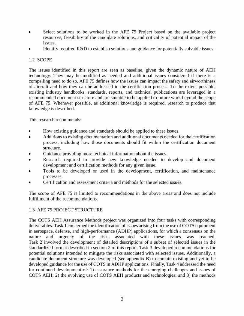
• Select solutions to be worked in the AFE 75 Project based on the available project resources, feasibility of the candidate solutions, and criticality of potential impact of the issues.
• Identify required R&D to establish solutions and guidance for potentially solvable issues. 1.2 SCOPE
The issues identified in this report are seen as baseline, given the dynamic nature of AEH technology. They may be modified as needed and additional issues considered if there is a compelling need to do so. AFE 75 defines how the issues can impact the safety and airworthiness of aircraft and how they can be addressed in the certification process. To the extent possible, existing industry handbooks, standards, reports, and technical publications are leveraged in a recommended document structure and are suitable to be applied to future work beyond the scope of AFE 75. Whenever possible, as additional knowledge is required, research to produce that knowledge is described. This research recommends: • How existing guidance and standards should be applied to these issues. • Additions to existing documentation and additional documents needed for the certification
process, including how those documents should fit within the certification document structure.
• Guidance providing more technical information about the issues. • Research required to provide new knowledge needed to develop and document
development and certification methods for any given issue. • Tools to be developed or used in the development, certification, and maintenance
processes. • Certification and assessment criteria and methods for the selected issues. The scope of AFE 75 is limited to recommendations in the above areas and does not include fulfillment of the recommendations. 1.3 AFE 75 PROJECT STRUCTURE
The COTS AEH Assurance Methods project was organized into four tasks with corresponding deliverables. Task 1 concerned the identification of issues arising from the use of COTS equipment in aerospace, defense, and high-performance (ADHP) applications, for which a consensus on the nature and urgency of the risks associated with these issues was reached. Task 2 involved the development of detailed descriptions of a subset of selected issues in the standardized format described in section 2 of this report. Task 3 developed recommendations for potential solutions intended to mitigate the risks associated with selected issues. Additionally, a candidate document structure was developed (see appendix B) to contain existing and yet-to-be developed guidance for the use of COTS in ADHP applications. Finally, Task 4 addressed the need for continued development of: 1) assurance methods for the emerging challenges and issues of COTS AEH; 2) the evolving use of COTS AEH products and technologies; and 3) the methods

3
for verifying compliance to the recommended COTS AEH assurance. Additionally, Task 4 outlined suggestions for future work required to implement the potential solutions. 1.4 DOCUMENT STRUCTURE
This report is organized into three major sections with supplemental appendices and is structured to provide parallel results and conclusions to allow this single document to provide documentation for each distinct issue. Section 1 introduces the AFE 75 Aerospace Vehicle System Institute Project and identifies the project’s objective, principles, structure, issue set, and document structure. Section 2 lists the candidate issues and specifies the issues selected for AFE 75 research; describes each issue and defines the relationship to safety and certification and existing activities, as well as technology and process weaknesses and deficiencies, recommendations, and desired outcomes; and includes a separate reference and acronym list, thus enabling each issue section to be a stand-alone segment. Section 3 defines how AFE 75 results and conclusions are embedded in the document structure. Appendix A provides the combined references from the entire report designed in a manner that provides a synchronized view of how the 22 issues relate to each other and to existing references and guidance documents. Appendix B (Candidate Comprehensive Guidance Document Structure) addresses a five-step evolution of Candidate Comprehensive Guidance Documents to project implementation of standards and guidance documents required to address the COTS issues to the level of accomplished AFE 75 research Appendix C contains a spreadsheet that provides a comparative matrix summary of the issues and aspects, which allows a detailed comparison in an abbreviated format. The spreadsheet identifies each of the selected issues within a column and a row for each of the following aspects of the issues: • References relevant sections in section 2.n • Identifies current standards • Does the current standard adequately address the issue defined? • Should a new standard be created? • Identifies standard owners • What additional work is needed for regulatory use? • Wherever possible, summarizes what additional research is needed Appendix D categorizes similarities in COTS AEH issues, which may support planning for additional research.

4
1.5 COTS AEH ASSURANCE OBJECTIVE
The COTS electronics products industry is characterized by relentless pressure to expand and improve functions, reduce costs, and reduce design and development time. These concerns are accelerating rather than abating. Since aerospace is only a small part of this market, this market is inevitably driven by forces that are beyond the control of the aerospace sector—and are often counter to the best interests of aerospace users of COTS products. Because of the dynamic nature of the COTS industry, the issues that impact aerospace continually change, and any attempt to capture them must be viewed only as a snapshot of any given timeframe. Furthermore, the issues are interrelated and difficult to organize. Nevertheless, the issues described here represent the best good-faith efforts of aerospace technical professionals in dealing with them. The AFE 75 Project Management Committee (PMC) has developed a consensus set of issues that existed at the time of this research project and has attempted to identify the needs and approaches of these issues to ensure safety and airworthiness of aircraft and to determine how they can be addressed in the certification process. 1.6 COTS AEH ISSUES
This research established 26 categories of candidate issues and selected 22 issues to be researched in AFE 75. Some candidate issues did not meet the AFE 75 criteria for COTS issues, whereas one (intellectual property) was beyond the resources available to the AFE 75 Project. Each selected COTS issue was evaluated to determine its technical characteristics and impact on aerospace design, component selection, implementation, validation, certification, and life-cycle maintenance. Special attention was given to the need for awareness of these issues by both industry and regulatory agencies to attain a level playing field based on an agreement regarding the required quality of systems and aircraft, and mitigation of the issue characteristics. Table 1 identifies the issues and non-issues identified and addressed in this report. A total of 22 issues were selected and four issues were not selected. In addition, the topic of “Multiple, Global Electronic Supply Chains” (section 2.12) was determined to not be a technological issue and, therefore, was not included in appendix C, but remains in section 2 for the purpose of completeness.

5
Table 1. AFE 75 candidate issues – selected and not-selected
Section Issue Issue/Non-Issue 2.1 COTS Assemblies Issue 2.2 Derating Issue 2.3 Sparing Reliability Issue 2.4 Commodity Memory Issue 2.5 Increased Susceptibility to Atmospheric Radiation Issue 2.6 Limited Life Semiconductors Issue 2.7 Outdated Reliability Assessment Methods Issue 2.8 Transition to Lead-Free Electronics Issue 2.9 Availability and Updates of Errata Issue 2.10 Counterfeit Electronic Parts Issue 2.11 Undocumented Features Issue 2.12 Multiple, Global Electronic Supply Chains Non-
Technological Issue
2.13 Usage Domain Analysis Issue 2.14 Production Follow-up Issue 2.15 Intellectual Property Issue 2.16 Unknown Changes Issue 2.17 Embedded Controllers Issue 2.18 Technology and Component Maturity Non-Issue 2.19 Component Packaging & Mounting Reliability Issue 2.20 Device Uprating Issue 2.21 Additional Handbook Considerations Issue 2.22 Obsolescence Management Issue 2.23 Acceptable Level of Compliance Evidence Non-Issue 2.24 Multiple Supply Chains See section 2.12 2.25 Demonstration Methods for Safe Use of Complex COTS in AEH Non-Issue 2.26 System on Chip Devices Issue
2. ISSUE DEFINITIONS AND RECOMMENDATIONS
This report provides a commercial off-the-shelf (COTS) AEH assurance framework including a common structured approach for industry use to evaluate COTS AEH issues. It is applied to the 22 issues and is recommended for application to future issues to support the development of COTS AEH mitigations on a project level that can be rolled into development design assurance and practical aircraft certification compliance solutions for FAA engineers, delegates, and standards administrators. Each section 2 issue is structured to include:

6
2.n.1 Description of the issue. 2.n.2 Relationship of issue to safety and certification. 2.n.3 Existing activity. 2.n.4 Technology weakness/deficiency. 2.n.5 Process weakness/deficiency. 2.n.6 Recommendation/desired outcome. 2.n.7 References. 2.n.8 Acronyms and abbreviations. This structured approach can be used to evaluate and process emerging COTS AEH issues. The subsections below (i.e., sections 2.1–2.26) are intended to be stand-alone resources for further work on each issue; each issue subsection contains a complete set of acronym definitions and references for this purpose. Reference numbering is self-inclusive within each subsection. A full, cross-referenced list of references is provided in appendix A. 2.1 COTS ASSEMBLIES
For the purposes of this project, COTS assemblies are viewed as small electronic assemblies, such as printed wiring assemblies, relays, disk drives, and liquid crystal display (LCD) matrices. Depending on the item, the aerospace user of the assembly may have varying levels of control, but never complete control, of the design, configuration control, and qualification of the COTS assembly; thus, a wide range of assurance methods may be used. This implies a wide range of costs, and there is a need for guidance for certification of systems that contain COTS assemblies. TechAmerica issued a COTS assembly management document (ANSI/EIA-933) [1] that may serve as a basis for that guidance. Recently, ownership of this and other aerospace documents has been transferred to SAE International (formerly the Society of Automotive Engineers); therefore, SAE International is used to designate such documents in this case. 2.1.1 Description of the Issue
Although there is no generally agreed-upon definition of a COTS assembly, the definition found in ANSI/EIA-933 is used here: “An assembly developed by a supplier for multiple customers, whose design and configuration is controlled by the supplier’s or an industry specification” [1]. There are many ways to categorize COTS assemblies, but for the purposes of this report, this categorization is best viewed as a spectrum. • At one end of the spectrum are COTS assemblies whose design, internal parts, materials,
configuration control, and qualification methods are at least partially or indirectly controllable by aerospace customers (either individually or collectively). An example at this end of the spectrum is a virtual machine environment (VME) circuit card assembly. While the design, internal parts, materials, configuration control, and qualification methods are controlled by the assembly manufacturers, the assemblies are targeted for aerospace applications and, thus, the manufacturers expend considerable effort to understand their customers’ needs—and they design, produce, and qualify their products accordingly. The VME assembly manufacturers are sensitive to feedback from their customers and are willing to make changes in response to that feedback. The response is only general,
7
however, and it is not likely that a specific change will be made unless the manufacturer determines it to be beneficial to the product’s overall market performance.
• At the other end of the spectrum are COTS assemblies whose design, internal parts, materials, configuration control, and qualification methods are not controlled, or controllable, in any way by aerospace customers (either individually or collectively). An example here is a disk drive targeted for an industry other than aerospace. Aerospace customers are not likely to obtain any information beyond the published data sheet; furthermore, the data sheet and other important information may be changed without notice. Typically, it is not possible for aerospace customers to purchase these assemblies by using a specific data sheet.
2.1.2 Relationship to Safety and Certification
In the typical developmental process, the manufacturer or supplier of any given COTS assembly is not within the control of the aerospace user of the assembly; therefore, it is the responsibility of the organization that integrates the COTS assembly into an aerospace system to assure the performance and reliability of the system. There is a wide range of approaches for assuring the performance and reliability of COTS assemblies in AEH systems. Unfortunately, and all too often, nothing is done to ensure performance and reliability because the user of the COTS assembly neither controls nor understands the design, parts, or materials used in the COTS assembly. However, it is possible for the user to conduct costly tests, analyses, and other activities to understand the design, performance, and configuration control of COTS assemblies. Clearly, there is significant potential for integrators of COTS assemblies to play on a field that is not level—and one way to level that field is with the certification process. The challenge, then, is for aerospace customers to have consensus on requirements and procedures to certify that all COTS assemblies placed into service in airborne electronics hardware have acceptable levels of reliability and performance. 2.1.3 Existing Activity
COTS assemblies and other forms of COTS have been discussed extensively in the aerospace, defense, and high-performance (ADHP) industries over the past two decades. A number of annual COTS-related conferences are held, and numerous books, journals, and technical papers related to COTS have been published. These activities have been largely application-specific and anecdotal, and there is a striking lack of consensus on any structured, systematic way to approach the challenge of COTS assemblies in AEH. The only known published standard for COTS assembly management is ANSI/EIA-933. Its scope states, in part: “The purpose of this document is to define the requirements for developing a COTS Assembly Management Plan (CAMP) to assure customers and regulatory agencies that all of the COTS (electronic) assemblies in the equipment of the plan owner are selected and applied in controlled processes; and that the technical requirements detailed in Clause 3 are accomplished. In general, the owners of a CAMP are electronics equipment and system manufacturers/integrators.”

8
Clause 3 of ANSI/EIA-933 includes the following requirements: • COTS assembly selection • COTS assembly application • Vendor selection • Configuration management and documentation • Life-cycle management Some of the requirements are applicable to the COTS assembly manufacturer and others must be accomplished by the user. ANSI/EIA-933 is published by SAE International, whereas the SAE Avionics Process Management Committee (APMC) [2] is responsible to maintain the document and any revisions to it. Recently, APMC began work to revise ANSI/EIA-933. The International Electrotechnical Commission (IEC) Technical Committee (TC) 107, Process Management for Avionics (TC 107) [3], has a COTS Assembly Management document in its current program of work, but nothing has yet been published on this topic. 2.1.4 Technology Weakness/Deficiency
There is no technology weakness or deficiency associated with this issue. 2.1.5 Process Weakness/Deficiency
There is no aerospace industry consensus on guidance for design or reliability assurance or the certification process for COTS assemblies in aerospace systems. 2.1.6 Recommendations/Desired Outcome
Although ANSI/EIA-933 is currently used by a variety of aerospace programs, in its current form it does not adequately address all the issues identified in AFE 75. It should be revised by determining the minimum set of requirements and procedures to certify that all COTS assemblies placed in service in airborne electronics hardware will have acceptable levels of reliability and performance and no adverse impact on safety. The introductory sub-clause to the requirements clause in the current draft of the proposed revision to ANSI/EIA-933 states:
A COTS Assembly Management Plan (CAMP) compliant to this document shall include documented processes that are available for use to accomplish the following, for the requirements listed in this clause:
(a) Understand the System requirements allocated to the COTS assembly;
(b) Understand the capability of the “as-received” COTS assembly, with respect to the allocated System requirements;

9
(c) Prepare a System risk analysis, based on a comparison of (a) and (b), above; and
(d) Document appropriate risk mitigation methods1 available for use to assure that the COTS assembly accomplishes its allocated System requirements reliably throughout the specified system lifetime.
The requirements in this Clause can be satisfied only by the Plan owner, and cannot be flowed down to a supplier, subcontractor, or other organization that is not responsible for the integration of the COTS assembly into the System.
The proposed revision also includes a “COTS Assembly Integration Report” to be used for each instance of integrating a COTS assembly into an aerospace system. It demonstrates that all the technical requirements of the proposed revision have been addressed and satisfied. Considerable work will be required to revise ANSI/EIA-933, and the SAE APMC has the capability to do so. The proposed revision satisfies the concerns expressed in this clause. IEC TC 107 also is preparing a COTS Assembly Management document. Because this document will address the same issues as does ANSI/EIA-933, IEC TC 107 and SAE APMC should be encouraged to work together on these two documents to assure not only that their requirements are consistent (identical if possible) but that they have the same look and feel so that users of the two documents will use the same processes to satisfy their requirements. The AFE 75 PMC endorses the work underway in IEC TC 107 and SAE APMC as part of Task 4 to address this issue and recommend that IEC and SAE consider producing a single document to avoid the inevitable divergence of two standards over time. The AFE 75 PMC recommends that certification authorities and avionics system customers (e.g., the Department of Defense and platform integrators) adopt IEC TC 107 and/or SAE APMC committee standards for COTS assemblies after they are released. 2.1.7 References
1. American National Standards Institute, Energy Information Administration, ANSI/EIA-933, Standard for Preparing a COTS Assembly Management Plan,” August 2001.
2. SAE International, “APMC Avionics Process Management,” available at http://www.sae.org/works/committeeHome.do?comtID=TEASSTCAPMC (accessed on 11/26/14).
1 The intent of this clause is for the plan owner to document the risk mitigation methods available to the plan owner, with the understanding that the risk mitigation methods actually employed on a given system depend on the application and criticality of that system. Examples of risk mitigation methods include modification of the COTS assembly, redundancy and other aystem design methods, modification of the COTS assembly’s local operating environment, increased maintenance, and planned replacement. More detail regarding these methods is included in appendix B.

10
3. International Electrotechnical Commission, Technical Committee 107, “Process Management for Avionics,” available at http://www.iec.ch/dyn/www/f?p=103:7:0::::FSP_ORG_ID:1304 (accessed on 11/26/14).
4. International Electrotechnical Commission/Technical Specification, IEC/TS 62239-1, “Process management for avionics - Management plan – Part 1: Preparation and maintenance of an electronic components management plan,” International Electrotechnical Commission, ed., Edition 1.0, July 2012.
2.1.8 Acronyms
The following acronyms were used in section 2.1. AEH Airborne electronic hardware AFE Authorization for Expenditure ANSI American National Standards Institute APMC Avionics Process Management Committee CAMP COTS Assembly Management Plan COTS Commercial off-the-shelf EIA Energy Information Administration IEC International Electrotechnical Commission LCD Liquid crystal display TC Technical Committee VME Virtual machine environment 2.2 DERATING
2.2.1 Description of the Issue
Most of the definitions of derating are similar and relate to enhanced components reliability. Tarr, for instance, describes derating as “operating a component well inside its normal operating limits, in order to reduce the rate at which the component deteriorates” [1]. The use of commercial off-the-shelf (COTS) components for safety-critical applications may require derating of the component. This derating serves to reduce stresses on the COTS component, which leads to longer service life and higher assessed reliability for the host assembly. The avionics guideline IEC/TS 62239 [2] states that if the manufacturer provides derating guidelines, they shall be used. If they are not provided, the applicant shall develop and document appropriate derating criteria. There are several concerns with derating of modern COTS components. 2.2.2 Relationship to Safety and Certification
Derating, from a reliability perspective, can be used to reduce the semiconductor component’s scaling-related internal stress. If the internal stress decreases, the likelihood of the component time

11
dependent wear-out and failure in long-life applications also decreases. However, to arbitrarily derate COTS components by following outdated derating rules might lead to decreased lifetime and reliability — and to properly derate COTS components requires knowledge of the internal design and manufacturing process, which in numerous cases may not be available for aerospace users. 2.2.3 Existing Activity
Derating of COTS components has been investigated and revealed by, for example, Forsberg and Månefjord [3]). The authors describe derating of voltage, frequency, temperature, current, noise and transients, time, and some combinations of these parameters, and they reveal parameter derating concerns for microcontrollers (e.g., voltage, frequency, input/output [I/O], and current). There are also other concerns, such as downbinning2, power-aware architectures3, and process-related scaling issues. More recent work has been performed by M. White [4], who also reveals some derating concerns (e.g., dynamic random-access memories [DRAMs], for which the internal voltage used for access transistors may be derived internally and cannot be affected by the external power supply voltage). 2.2.4 Technology Weakness/Deficiency
A typical wear-out mechanism in semiconductors is electromigration, which is the transport of material caused by the gradual movement of the ions in a conductor due to the momentum transfer between conducting electrons and diffusing metal atoms). By derating the frequency of a highly integrated circuit—such as a microprocessor or digital signal processor (running it at lower speeds at a given temperature)—the power consumption will decrease, which in turn reduces electromigration. Reference “Reliability implications of derating high-complexity microcircuits” [5]. Thus, it makes sense to derate the frequency of such components. However, some manufacturers may have used power-reduction techniques, such as advanced cutoff techniques, making the effect of frequency derating non-trivial concerning both performance and wear-out. In addition, in many COTS components, there are different frequencies on different parts on the chip; this presents problems as to what frequency to derate. There might also be relationships between different frequency regions that need to be maintained. Internal frequencies might also be tightly coupled to memory and I/O bus speeds. Therefore, it is very important to fully understand all frequency regions and their relationships to each other or other external environments before applying frequency derating of such components. Reference “Derating Concerns for Microprocessors Used in Safety-Critical Applications” [3].
2 A COTS manufacturer reserves the right to fulfill orders by delivering higher frequency components substituting for the original ones that were ordered. These faster components may have higher static power dissipation and faster edge rates. Faster edge rates can impact signal timing analysis, electromagnetic interference, and decoupling capacitors considerations.
3 Typical power-aware architectures are declocking of execution units, different power sleep modes, dynamic voltage/frequency switching, or power throttling (i.e., to cool down a device by turning off/slowing down execution units when a certain die temperature is reached).

12
2.2.5 Process Weakness/Deficiency
Several derating guidelines exist, but many of them are outdated. Also, when it comes to on-chip designs, where the knowledge of the internal design plays a big role, not much derating guidance exists. However, two standards—IEC/TS 62239-1 and ANSI/EIA-STD-4899-A-2009 [6]—require the applicant to follow the component manufacturer’s derating criteria and methods, if existent. The assumption behind this is that the manufacturer knows its own internal design and manufacturing process best and, therefore, develops the most accurate derating guidance based on this knowledge. Conversely, developers of today’s components may not be the same as the manufacturer of the components, which may not be the same as the ones producing the wafers with the integrated circuits that control the manufacturing process. Developers may also use purchased intellectual property functionality from other companies, thus having less control over the internal design. In addition, the avionics applicant may also have other conditions not typically valid for the mainstream users of the component, which make the manufacturer’s derating criteria difficult to use. In the end, however, it is most likely that the manufacturer has better control over the internal design and manufacturing process than the applicant. Other guidance addresses particular derating topics, for example, IEC/TS 62396-1 [7], which addresses single-event burnouts for high-voltage components and recommends voltage derating more than 50% for power components operated at > 300 volts (V). From the military side, standards and handbooks give some derating guidance: • The Military Standard, MIL-STD-1547B [8], requires a specific derating to be performed,
solely based on temperature, for space and launch vehicles. • The Military Handbook, MIL-HDBK-454B [9], states that the parts and materials selected
should be used within their electrical ratings and environmental capabilities. Derating should then be accomplished as necessary to ensure the required equipment reliability within the specified operating conditions. However, to do so requires knowledge of mapping derating parameters to reliability.
• The MIL-HDBK-338B [10] provides guidance on the specific parameters to be derated for each type of component. This handbook has, however, not been updated for several years, which affects its usefulness for new types of components.
2.2.6 Recommendation/Desired Outcome
It should be clear that the issue described in this section does not apply to components for which no derating is performed. The issue appears only when derating is applied. It should also be noted that derating is not mandatory for certification. If derating shall be applied, there are only two appropriate standards for avionics system applications. They are IEC/TS 62239-1 or ANSI/EIA-STD-4899-A-2009. Their recommendations for derating are: • When the component manufacturer provides derating criteria and methods, they shall be
used.

13
• If the component manufacturer does not provide this information, then the applicant shall develop and document appropriate4 derating criteria and methods.
• All instances in which a component is not used within the operating limits specified by the component manufacturer (uprating) shall be documented in the design records. In all such instances, either corrective action shall be taken or justification for not satisfying the criteria shall be documented. See also the specific topic Device Uprating (section 2.20) in this document.
By enforcing the use of the component manufacturer’s derating criteria and methods, the likelihood for unsuccessful derating of a component will likely decrease. If the component manufacturer does not provide derating criteria, both IEC/TS 62239-1 and ANSI/EIA-STD-4899-A-2009 recommend using derating methods described in JEP149 [11] for avionics applications. To be able to use JEP149, internal parameters and technical data used for component thermal modeling should be documented with the component manufacturer data. Also, for some processes to be performed, information from the component manufacturer not provided in published data sheets may be required. In these cases, the manufacturer shall be contacted to determine the data needed to support appropriate application of the part with regard to these issues. Because IEC/TS 62239-1 and ANSI/EIA-STD-4899-A-2009 reference JEP 149, these standards should be applied with caution when JEP149 is used for extending the service life of the component, since detailed component information is needed. Without detailed information of the component, it is not practical to apply JEP149. When using JEP149 with assumptions, these assumptions may be required to be explained to the certification authorities before use; and this use may be applied as the model and process when derating is used for design margins. It is recommended that when either IEC/TS 62239-1 or ANSI/EIA-STD-4899-A-2009 is the subject for other updates, these standards’ derating sections should be updated with a caution note regarding the use of JEP149 for extending the service life of the component, because detailed component information is needed, to include guidance concerning how JEP149 may be applied when derating is used for design margins. See above as it relates to explanation needed by certification authorities. If derating is performed, IEC/TS 62239-1 or ANSI/EIA-STD-4899-A-2009 should be adopted as the guidance document as soon as possible. The issue appears only when derating is applied. It should also be noted that derating is not mandatory for certification. The AFE 75 PMC has no further recommendations.
4 The authors are not aware of any criteria or standard defining appropriate derating criteria and methods. Thus, it is likely that the applicant needs to define and argue for what are appropriate means in this context and coordinate this with the certification authorities to ensure its appropriateness for aircraft certification.

14
2.2.7 References
1. Tarr, M., “Derating,” Online postgraduate courses for the electronics industry – Topics Library, Reliability issues and failure mechanisms, The University of Bolton, http://www.ami.ac.uk/courses/topics/0190_drat/index.html (accessed on 12/04/2014).
2. International Electrotechnical Commission/Technical Specification, IEC/TS 62239-1, “Process management for avionics – Management plan – Part 1: Preparation and maintenance of an electronic components management plan,” International Electrotechnical Commission, Edition 1.0, July 2012.
3. Forsberg, H. and Månefjord, T., “Derating Concerns for Microprocessors Used in Safety-Critical Applications,” IEEE Aerospace and Electronic Systems Magazine, March, 2009.
4. White, M., “Scaled CMOS reliability and considerations for spacecraft systems: Bottom-up and Top-down Perspectives,” Reliability Physics Symposium (IRPS), 2012 IEEE International, Anaheim, CA, April 15–19, 2012.
5. Biddle, S.R., “Reliability implications of derating high-complexity microcircuits,” COTS Journal, Vol. 2, No. 2, February 2001.
6. TechAmerica Standard, ANSI/EIA-STD-4899A-2009, “Standard for preparing an electronic components management plan,” February 2009.
7. International Electrotechnical Commission/Technical Specification, IEC/TS 62396-1, “Process Management for Avionics – Atmospheric Radiation Effects – Part 1: Accommodation of Atmospheric Radiation Effects within Avionics Electronic Equipment, Edition 1.0, March 2006.
8. Military Standard, MIL-STD 1547B, “Electronic parts, materials, and processes for space and launch vehicles,” December 1992.
9. Military Handbook, MIL-HDBK-454B, “General guidelines for electronic equipment,” APRIL 2007.
10. Military Handbook, MIL-HDBK 338 B, “Electronic reliability design handbook,” October 1998.
11. Joint Electronic Device(s) Engineering Council (JEDEC), Solid State Technology Association, JEP149, “Application thermal derating methodologies,” November 2004.
2.2.8 Abbreviations and Acronyms
The following abbreviations and acronyms were used in section 2.2. V Volts ANSI American National Standards Institute CA California CMOS Complementary-metal-oxide-semiconductor COTS Commercial off-the-shelf DRAM Dynamic random-access memory EIA Energy Information Administration HDBK Handbook IC Integrated circuit IEC International Electrotechnical Commission IEEE Institute of Electrical and Electronic Engineers I/O Input/output

15
IRPS International Reliability Physics Symposium JEP JEDEC Publication MIC Many Independent Core MIL Military TS Technical Specification

16
2.3 SPARING RELIABILITY
2.3.1 Description of the Issue
As feature sizes decrease and processes and materials change continuously, the potential for on-chip defects increases. Device manufacturers can counter this with “sparings” (i.e., on-chip redundancy to improve wafer yield). Sparings can also be used for lifetime reliability enhancement, for which spare structures are turned on when the original structures fail. On-chip redundancy to improve wafer yield has been used for a long time by manufacturers of commercial off-the-shelf (COTS) electronics products aimed at the consumer market. Intel presented ideas for improving wafer yield using on-chip redundancy for static random access memory (SRAM) in 1997 [1]. A well-known example of sparings is Sony’s PlayStation 3. The PlayStation 3’s Cell microprocessor—designed by Sony, Toshiba, and IBM—is its CPU; it is made up of one PowerPC-based power processing element and eight synergistic processing elements (SPE). To increase fabrication yields, Sony ships PlayStation 3 Cell processors with only seven working SPEs [2]. Another recent multicore device, Intel’s Knights Corner (KNC), also uses on-chip redundancy to improve wafer yield. But in this case, the number of usable cores also depends on other factors such as clock speed. T.P. Morgan [3] writes, “Intel has been cagey in public talking about how many cores are physically on the Knights Corner coprocessor, and has only committed to saying that it is going to be larger than 50. The real answer is that there are 64 cores on the die, and depending on yields and the clock speeds that Intel can push on the chip, it will activate somewhere between 50 and 64 of those cores and run them at 1.2 GigaHertz (GHz) to 1.6 GHz.” 2.3.2 Relationship to Safety and Certification
It is known that at least one embedded microcontroller suitable for the avionics industry is sold as a single core but is in fact a defective dual core. The manufacturer has revealed that both cores must be powered even though only one should be used. To avoid accidental execution of the incorrect working core, a “core disable” pin must be set to ground. Execution of “unknown cores,” defective or not, may affect shared resources, such as common cache memories, such that the expected working core experiences unwanted undeterministic behavior. Another concern is that if one core is only slightly defective, this microcontroller may be potentially remarked and sold as a working dual core. For the avionics industry—in which frequency derating is more common than other industries—both cores may work well at the derated frequency, but the margins for failure are much closer than were originally calculated. Furthermore, researchers have proposed ideas to use redundancy at finer granularities to achieve more efficient use of redundant hardware. The extent of that concern for the certification process is not fully understood.

17
2.3.3 Existing Activity
Srinivasan et al. [4] have studied two techniques of sparings that leverage microarchitectural structural redundancy for lifetime reliability enhancement. The first technique, structural duplication, uses redundant microarchitectural structures in the processor, which are designated as spares. Spare structures can be turned on when the original structure fails (in extreme cases already at shipment to counteract on-chip defects during manufacturing), increasing the processor’s lifetime without loss of performance—but adds to the cost because of increased die size. The suggested solution relies on power gated spare structures; thus, it is not expected that the effect of single-event upsets will change during the lifetime of the device. Using this technique, however, leads to another challenge—the assured shutting down of the failed structure. The technique should ensure that units that are shut down do not become active again and that units cannot be shut down by false failure indications, thus possibly causing other units to cascade into a shut-down condition. The other described technique is called graceful performance degradation (GPD). It is a technique that exploits existing microarchitectural redundancy for reliability. Redundant structures that fail are shut down while still maintaining functionality but at a lower performance. As long as the manufacturer reveals the eventual performance loss due to this technique, it still may be possible to maintain a controlled behavior. It may, however, be harder to evidence and create safety nets for them. Pan et al. [5] have proposed a similar technique as the GPD but on a coarser granularity. Their approach improves reliability on chip multiprocessors and at the same time improves the yield but at the cost of some performance loss. They exploit the natural redundancy that already exists in multi-core systems by using services from other cores for functional units that are defective in a faulty core. To make it work, they use a micro-architectural modification that allows a core on a chip multiprocessor to use another core as a coprocessor to service any instruction that the former cannot execute correctly. Through a simulation of a dual-core system with one or two cores sustaining partial failure, Pan et al. have shown that large and sparingly used units, such as floating point arithmetic units, can run each faulty core with help from companion cores with low impact to their performance and little increase to the overhead of the area occupied by the cores. Their simulation shows that significant yield recovery is possible with only 10%–15% performance degradation in the worst case. However, through normal maintenance activities, the margin of performance available may become small enough to allow even low impact to cause degraded performance. In addition, to predict worst-case execution times on these types of devices, the manufacturer has to provide built-in test features for which it is possible to simulate all kinds of faults that can be mitigated through delayed and shared (during faults) services from other cores. Still, it might be hard to understand the non-deterministic behavior in real applications with multicore processors that implement this microarchitectural modification. Another example of sparings is used in some IBM Power 7 servers. These servers provide a “self-healing capability” in memory—automatically moving data from failed dynamic random access memory chips to available spares [6].

18
2.3.4 Technology Weakness/Deficiency
Using redundancy to improve yield will become more evident in relation to the smaller geometries used by the manufacturer for several reasons. For example: higher transistor count, increased clock frequencies, reduced effectiveness of accelerated life tests (burn-ins), and new aging defect mechanisms, such as negative bias temperature instability, positive bias temperature instability, and time-dependent dielectric breakdown [5]. It could be argued that devices with redundancies be considered as part of the failsafe or operational safety net requiring additional capacity to counteract loss of performance due to repetitive failure. However, research [7] has shown a clear relationship between failure rates and technology scaling. This indicates that microarchitectural redundancy should preferably be seen as an enabler for using smaller geometry devices rather than as a part of an operational safety net (unless it is purposely used for fault-tolerance purposes such as IBM’s Power6 microprocessor [8]). 2.3.5 Process Weakness/Deficiency
The authors are not aware of any process guidance for safety-critical systems dealing with devices using yield improvement technologies. It seems as if failures will occur in development and operation, thus changing the risks and characteristics of the devices. Accordingly, certain questions arise, such as: Should requirements for continuing evaluations in the operational environment be developed and required? Should devices containing such redundant architecture be used in avionics systems? What requirements are needed to reduce operational risks? 2.3.6 Recommendation/Desired Outcome
The AFE 75 PMC details that sparings are not yet ready for regulatory use and should not be used when it may affect performance and deterministic behavior. Professional-level research across the integrated circuit industry is needed to better understand the scope of this problem. The avionics industry should, however, be aware of this potential effect on performance and deterministic behavior because, in some examples, it is apparent that sparings may have uncontrolled impact on both of these. The AFE 75 PMC advises that university-level research be conducted to assess different types of sparings (e.g., coarse versus fine grain, with or without shared resources), to what extent they are used by the manufacturer today, and what potential impact they may have to the avionics industry. The results of the research would include the creation of specific processes and objectives that address these associated findings/issues. In addition, the AFE 75 PMC recommends that regulatory agencies issue guidance that incorporates those research results. Finally, the AFE 75 PMC recommends the generation and distribution of a white paper that describes the issues, along with recommended practices and direction, for the semiconductor industry. Sparings should preferably be divided into two problem domains: • When redundancy techniques are used for improving yields or extending the lifetime of the
device (with or without performance degradation) and are not visible to the customer.

19
• When these techniques are used and are visible to the customer. The focus should then be on understanding the extent to which sparings are used and are not visible to the customers. If the techniques are visible, usage domain analysis may be seen as alternative guidance material; see Usage Domain Analysis in this document’s section 2.13.
2.3.7 References
1. Ramadan, N.H., “Redundancy Yield Model for SRAMS,” Intel Technology Journal, 1997. 2. Linklater, M., “Optimizing Cell Code,” Game Developer Magazine, April 2007: pp. 15–
18. 3. Morgan, T.P., “Hot Intel teraflops MIC coprocessor action in a hotel,” The Register,
November 2011. 4. Jayanth, S. et al., “Exploiting structural duplication for lifetime reliability enhancement,”
ISCA ’05 Proceedings, 32nd International Symposium on Computer Architecture, June 2005, pp. 520–531.
5. Pan, A. et al., “Improving Yield and Reliability of Chip Multiprocessors,” 2009 Proceedings of the Conference on Design, Automation and Test in Europe, Nice, France, April 20–24, 2009, pp. 490–495.
6. Henderson, D. et al., “Power7 system RAS: Key aspects of power systems reliability, availability, and serviceability,” IBM Server and Technology Group, August 23, 2010.
7. Jayanth, S. et al., “Lifetime Reliability: Toward an Architectural Solution,” IEEE Micro, May–June 2005.
8. Reick, K. et al., “Fault-Tolerant Design of the IBM Power6 Microprocessor,” IEEE Micro, March–April 2008.
2.3.8 Acronyms
The following acronyms were used in section 2.3. AFE AVSI Authorization for Expenditure AVSI Aerospace Vehicles Systems Institute COTS Commercial off-the-shelf GPD Graceful performance degradation Ghz Gigahertz IEEE Institute of Electrical and Electronics Engineers ISCA International Symposium on Computer Architecture KNC Knights Corner MIC Many Independent Core NBTI Negative bias temperature instability PBTI Positive bias temperature instability RAS Reliability, availability, serviceability SPE Synergistic processing elements SRAM Static random access memory TDDB Time dependent dielectric breakdown

20
2.4 COMMODITY MEMORY
2.4.1 Description of the Issue
Modern dynamic random access memory (DRAM) and Not-AND (NAND) flash memories bring tremendous value to electronic products. Their high capacity, compact packaging, and modest costs make them attractive for product markets of all types, including safety-critical products such as avionics. Their use in the high-volume consumer electronics market has made them commodity devices because of pricing pressures. These devices contain billions of transistors. To achieve this level of capacity, memory suppliers use aggressive feature sizes and layout techniques, complex design approaches (e.g., multi-level cell NAND), smaller design margins, and smaller noise margins [1–3]. Because of commoditization, the need for high yield has pushed suppliers to use smaller test margins and adaptive test flows, which are based on the results of recently tested die [4, 5]. These practices reduce the robustness of these devices’ manufacturing tests. These techniques and approaches make modern memory devices less reliable than earlier-generation devices. Error detection and correction circuitry is needed to make modern commodity memory devices more reliable and thus suitable for use in avionics. For sufficient error detection and correction to be determined, fault distribution models will need to be developed that are adapted to the avionics environment (e.g., temperature and neutron single-event upset [NSEU]) and the avionics equipment lifetime (20 years or more). These models would provide failure distributions and rates for various failure modes, such as gate oxide degradation due to program/erase cycles and read disturb errors due to successive reads without intervening program/erase cycles. If provided by the device memory suppliers, the models would enable the development of more reliable avionics and allow consistent application of these devices by avionics suppliers. 2.4.2 Relationship to Safety and Certification
Error-detection and correction methods for both DRAM (i.e., Hamming codes) and NAND flash (i.e., cyclic codes) are well known, trusted, and extensively employed [6, 7]. These methods are heavily used in avionics. Their effectiveness can be quantified for bit errors of any size and used in the fault trees for high-integrity systems. If the methods are not used, DRAM and NAND flash present significant data integrity challenges for designers of avionics. If an appropriate level of error detection and correction is used, data integrity is ensured and the main concerns will be limited to reliability and availability. 2.4.3 Existing Activity
Within the aerospace industry, several activities within the Aerospace Vehicle Systems Institute (AVSI) are addressing integrated circuit reliability, including AFE 17, AFE 70, AFE 71, AFE 80, and AFE 83. Many individual aerospace companies are addressing commercial off-the-shelf (COTS) reliability, including commodity memories [8]. In addition, the integrated circuit industry addresses integrated circuit reliability [9].

21
2.4.4 Technology Weakness/Deficiency
Pressure to reduce test time for DRAM has opened the possibility for devices with “weak-bits” to escape from memory manufacturers and be used in high reliability products. Reference [10] is one of a few studies which attempts to gather and quantify real-world DRAM reliability results. The very high density and relatively high voltages in NAND flash make these devices susceptible to several “disturb” errors (“read,” “program,” and “pass” disturb errors) [3]. These errors are “soft” in the sense that they are not destructive. Note, however, that NAND flash is a non-volatile memory. The errors remain until the block is erased and the page is re-programmed. Program/erase wear-out is also a major concern for NAND flash. Error detection and correction, usually via cyclic codes, provide a safety net for these errors. However, the amount of correction necessary is growing at a rapid pace. Without accurate fault-distribution models, an accurate assessment of the amount of error correction necessary for a given application is difficult to determine. Other NAND reliability concerns include fast wear-out in cases where “wear-leveling” is not done, data retention (leakage from the floating gate), and the practice of selling NAND with defective cells (usually limited to 1% of the cells) [3, 9]. Note that the use of “integrated” solutions for NAND flash (e.g., multimedia card and variants) does not necessarily address this issue. These solutions integrate the NAND memory, an industry standard interface, and memory controller into one package [3]. While error detection and correction are usually included in the memory controller, the long-term reliability may or may not be properly addressed in these designs. For example, if the controller did not account for the avionics lifetime, or expected a certain wear-leveling algorithm to be used, the reliability of these solutions would be much less than expected. In addition, third-party design of the controller may present other design-assurance questions. 2.4.5 Process Weakness/Deficiency
There is no standardized process to obtain fault-distribution models from memory suppliers. For some suppliers and devices, development of fault distribution models based on source information from the suppliers would be acceptable. These models need to be adapted to the avionics environment (e.g., temperature, NSEU) and avionics equipment lifetime (20 years or more). Other devices will require additional information and assistance from the supplier to develop models suitable for the avionics environment. 2.4.6 Recommendation/Desired Outcome
The AFE 75 PMC recommends that further research be performed by a university on this issue. If the university approach proves unsuccessful, collaborative research with memory manufacturers is recommended. A desired outcome is the creation of an aerospace working group (WG), which builds a framework for collaboration between commodity memory suppliers and the aerospace industry. The WG (e.g., the Joint Electronic Device(s) Engineering Council) would address the development and use of fault distribution models and the required error detection and correction for commodity memories suitable for the lifetime and environments of avionics equipment.
22
In addition, the commodity memory industry could benefit from additional research to further describe the problems, explain the reasons for concern, and provide recommendations to assist the aerospace community when using these memories in their products. 2.4.7 References
1. Keeth, B., Baker, R.J., Johnson, B., and Feng, L., “DRAM Circuit Design: Fundamental and High-Speed Topics,” IEEE Press Series on Microelectronic Systems, Wiley-IEEE, 2007.
2. Baker, R.J., “DRAM Circuit Design, Layout, and Simulation,” 3rd Edition, IEEE Press Series on Microelectronic Systems,” Wiley-IEEE, 2010.
3. Micheloni, R., Crippa, L., and Marelli, A., “Inside NAND Flash Memories,” Springer, 2010.
4. “International Technology Roadmap for Semiconductors, Test and Test Equipment,” 2011, http://www.itrs.net/reports.html, 2012 Update (accessed on 11/04/2015).
5. “International Technology Roadmap for Semiconductors, Lithography,” 2011, http://www.itrs.net/links/reports.html, 2012 Update (accessed on 11/04/2015).
6. Hsiao, M.Y., “A Class of Optimal Minimum Odd-weight SEC-DED Codes,” IBM Journal of Research and Development, 1970.
7. Siewiorek, D.P. and Swarz, R.S., “Reliable Computer Systems Design and Evaluation,” 3rd Edition, AK Peters, 1998.
8. Moliere, F. et al., “A New Policy for COTS Selection: Overcome the DSM Reliability Challenge,” SAE International Journal of Aerospace, Vol. 4, No. 2, pp. 1475–1484, November 2011.
9. Joint Electronic Device(s) Engineering Council Publication JEPP122G, “Failure Mechanisms and Models for Semiconductor Devices,” October 2011.
10. Schroeder, B., Pinheirom, E., Weber, W.D., “DRAM Errors in the Wild: A Large-Scale Field Study,” SIGMETRICS/Performance ’09, June 15–19, 2009, http://dl.acm.org/citation.cfm?doid=1555349.1555372 (accessed on 12/04/2014).
2.4.8 Acronyms
The following acronyms were used in section 2.4. AFE 17 Methods to Account for Accelerated Semiconductor Wearout AFE 70 Integrated Reliability Processes AFE 71 Reliability Prediction Software AFE 80 Integrated Reliability AFE 83 Semiconductor Reliability AVSI Aerospace Vehicle System Institute COTS Commercial off-the-shelf DED Double error detection DRAM DRAM Dynamic random-access memory IBM International Business Machine IC Integrated circuit IEEE Institute of Electrical and Electronics Engineers NAND Not AND, i.e. negation of Logical “AND”

23
NSEU Neutron single event upset SEC Single error correction 2.5 INCREASED SUSCEPTIBILITY TO ATMOSPHERIC RADIATION
2.5.1 Description of the Issue
Logic, memory, field-programmable gate array (FPGA), and other complementary metal-oxide semiconductor (CMOS) devices are susceptible to a broad class of atmospheric radiation effects called single event effects (SEE) that can result in data corruption and system faults. These phenomena are the result of the interaction of high-energy cosmic rays with the earth’s atmosphere, which produces high-energy neutrons that can cause SEE. SEE are more likely to occur at the altitudes in which commercial aircraft operate than at sea level, where most commercial off-the-shelf (COTS) electronics products are targeted for operation. The critical charge required to cause SEE decreases as feature sizes shrink and the likelihood of multiple-bit and multiple-cell events increases; thus, the effects of atmospheric radiation on avionics systems become more troublesome. 2.5.2 Relationship to Safety and Certification
There always will be a need for more information, data, and understanding of the nature of atmospheric radiation and its impact on avionics systems; however, the most immediate need is to synthesize currently available knowledge into a set of requirements or guidelines that normalize the process for certification analysis with respect to the impact of SEE on safety. This is necessary to ensure that the proper steps are being taken to mitigate the effects of SEE and to ensure that all providers of avionics systems are operating with the same set of rules consistently applied. 2.5.3 Existing Activity
There is currently no consensus on how to address SEE in AEH safety and certification processes. There is no consistency among various aerospace system stakeholders (e.g., platform integrators or system manufacturers) regarding how, or even whether, to require avionics system manufacturers to address the effects of atmospheric radiation in their products. The result is that the “solutions” used by the manufacturers range from completely ignoring the issue to conducting extensive, costly, and time-consuming tests and analyses at various stages in the design, production, operation, and support of avionics systems — and at various indenture levels within the systems. The result of this situation is that system manufacturers often are not operating with the same set of rules in system development — and certification analysts do not have a consistent set of rules to follow when evaluating certification applications with respect to SEE. The result is that a wide range of certification methods (up to and including ignoring the issue altogether) are being used inconsistently. In addition, this nonstandard approach to SEE can result in a wide range of costs and performance of AEH. This issue is also the focus of another Aerospace Vehicle Systems Institute (AVSI) project, AFE 72, which has issued additional technical reports [1]. AFE 72 also has recommended certification guidance for mitigating the effects of atmospheric radiation, but that guidance has not yet been

24
accepted by SAE S-18 nor EUROCAE WG-63 [2], the committees responsible for the development of the standards. AFE 72 is currently contributing to the following standards: • IEC TS 62396 series [3–7]. • There is a sixth part of this series under consideration. This additional part will address the
extreme space weather impact on airborne systems. • A draft revision to ARP4761 [8], through a draft Aerospace Information Report [9] to
address SEE. • Plans to support updates to JEDEC Standard JESD89 [10]. Currently underway via an IEC
TC47 WG. Both the FAA and European Aviation Safety Agency (EASA) have begun to take steps to require applicants to address SEE. In addition, the FAA and EASA are supporting the AFE 72 group working with WG-63 in the development of the above ARP4761 and draft Aerospace Information Report. RTCA DO-248C [11] also discusses SEE and mitigation techniques but does not recommend any action. 2.5.4 Technology Weakness/Deficiency
Logic, memory, FPGA, and other CMOS devices are susceptible to a broad class of atmospheric radiation effects called SEE that can result in data corruption and system faults. These phenomena are the result of the interaction of high-energy cosmic rays with the earth’s atmosphere, which produces high-energy neutrons that can cause SEE. In the approximately 20 years since aircraft electronics were first observed to be susceptible to errors induced by neutrons generated by cosmic rays within the atmosphere, the topic of SEE has become increasingly important and difficult to manage. The issue is especially critical to aerospace electronics because the flux density of atmospheric neutrons at an altitude of 40,000 feet is approximately 300 times that at sea level. As technology trends continue toward smaller feature sizes and lower voltages, CMOS devices are becoming more susceptible to atmospheric radiation effects. Government and customer specifications increasingly require assessments of the probability of SEE and their impacts to the safety and reliability of avionics systems. The actual number of these documents is growing very quickly. In addition, the level of details in the documents is also accelerating. It is important to distinguish between the effects on electronics caused by atmospheric radiation and those effects caused by radiation found in space. For electronics operating in space, the radiation of most concern is that of heavy ions and protons. Radiation’s intensity is usually described in terms of total dose. For electronics operating within the earth’s atmosphere (from sea level up to about 80,000 feet), atmospheric neutrons are the dominant cause of concern. Over the past several decades, considerable effort has been exerted to address and mitigate the effects of space radiation, such as the use of radiation-hardened devices and extensive testing and selection

25
of semiconductor devices used in space applications. Generally, the cost of the methods used to address space radiation cannot be justified for electronics operating within the earth’s atmosphere. Cosmic rays, which generate high-energy neutrons, are constantly bombarding the earth. The flux varies with global position, altitude, and solar activity, but all surface locations are exposed to this radiation. At the altitudes seen by aircraft, neutrons are the main area of concern and have been shown to be most responsible for causing SEE in avionics. Interactions of neutrons with semiconductor device active charge regions cause SEE and can take on various forms, such as upsets, functional interrupts, and latch up. When cosmic rays penetrate the magnetic fields of the earth and reach the earth’s atmosphere, they collide with atomic nuclei and create secondary radiation, which leads to a high flux of energetic particles. These secondary particles include neutrons, protons, and pions—with the neutron being most prevalent. Neutron energies range from 1–1,000 million-electron-volts (MeV) and are able to interact with silicon-based technologies. Figure 1 (reproduced from [3]) shows the energy spectrum at 40,000 feet and 45 degrees latitude.
Figure 1. Energy spectrum of atmospheric neutrons at 40,000 feet and 45 degrees latitude
1×10²
Neutron energy (MeV)
Neu
tron
diffe
rent
ial f
lux
(n/
cm2 ×
s M
eV)
Boeing model - Fit to 1974 NASA Ames flight data Hess measured spectrum, 1959 Armstrong calculated spectrum, 1973 1997 ER-2 measurements, Bonner spheres
1×101
1×100
1×10⁻¹
1×10⁻²
1×10⁻³
1×10⁻⁴
1×10⁻⁵ 1×10⁻³ 1×10⁻² 1×10⁻¹ 1×100 1×101 1×10² 1×10³ 1×10⁴

26
The flux density of the neutrons depends on both latitude and altitude; the largest single variant is altitude. Typical commercial airliners operate up to 40,000 feet when the flux density is approximately 300 times greater than that at sea level. There are several reasons why the risk of SEE in avionics electronics systems is increasing: • Technology is trending toward smaller feature sizes, higher densities, and lower voltages,
resulting in greater susceptibility to atmospheric neutrons. • The number of memory bits and registers are greatly increasing. • The number of flights at higher altitudes is increasing because of better fuel efficiency. • The number of polar flights is increasing. The result of having SEE occur in avionics ultimately can become a design issue for all airborne and high-reliability ground-based systems. While most neutrons passing through a semiconductor device will have no impact, those that do strike silicon atoms can flip bits. They can cause systematic functional operational errors on complex semiconductor microcircuits including devices such as memories, microprocessors, and programmable devices. SEE are caused when a radiation-generated ionization charge exceeds a device critical charge. Because secondary neutrons are uncharged, they do not generate ionization directly. Rather, the neutrons collide with atoms in the electronic device—normally silicon atoms—momentum is transferred, and the recoil generates ionization. Deposited charges, through the recoils they create within a sensitive portion of a device, result in malfunction of the device. The probability for a SEE to occur at a particular energy is determined by the device’s cross section for that effect. SEE can cause various failure conditions, such as data corruption or even system failure. Additional types of undesirable effects include: • Damage to hardware. • Corrupted logic residing in volatile memory. • Corrupted data in memory. • Microprocessor halts and interrupts. • Writing over critical data tables. • Unplanned events, including loss of mission.
2.5.5 Process Weakness/Deficiency
The International Electrotechnical Commission (IEC) has issued a series of documents that provide extensive technical background and guidance on this issue [3–7]; however, this and other knowledge in the field have not been translated into formal guidance that is available and easy to use by device manufacturers, AEH users, and regulatory agencies. The different types of SEE, and the associated circuit response, are defined in table 2. When measuring a system’s SEE susceptibility, the devices, probability of exposure, and functional unit criticality all need to be taken into account.

27
Table 2. SEE types
SEE Type Definition Circuit Response Single Event Upset (SEU)
In a semiconductor device when the radiation absorbed by the device is sufficient to change a cell’s logic state. Note: After a new write cycle, the original state can be recovered.
A change of state in a memory or latch in a device induced by the energy deposited by an energetic particle.
Multiple Bit Upset (MBU)
The energy deposited in the silicon of an electronic device by a single ionizing particle causes upset to more than one bit in the same word.
Occurs when the energy deposited in the silicon of an electronic device by a single ionizing particle causes upset to more than one bit in the same logical word.
Multiple Cell Upset (MCU)
The energy deposited in the silicon of an electronic device by a single ionizing particle induces several bits in an integrated circuit (IC) to upset at one time.
Occurs when the energy deposited in the silicon of an electronic device by a single ionizing particle induces bit upsets in more than one physically adjacent bit in an IC.
Single Event Latchup (SEL)
In a four layer semiconductor device, when the radiation absorbed by the device is sufficient to cause a node within the powered semiconductor device to be held in a fixed state whatever input is applied until the device is de-powered, such latch up may be destructive or non-destructive.
A condition that causes the loss of gate or device function or control because of a single-event induced high current state. May or may not cause permanent failure, but requires power cycling to return IC to normal operations if undamaged. Latchup can cause circuit lockup and/or device failure.
Single Event Transient (SET)
Spurious signal or voltage induced by the deposition of charge by a single particle that can propagate through the circuit path during one clock cycle.
A spurious signal or voltage propagating through a circuit path during a single clock cycle. Note: For frequency above 100 MHz, the potential for SET in digital devices increases. Produces transients, which may affect subsequent circuits if not well filtered in design.
Single Event Functional Interrupt (SEFI)
Occurrence of an upset, usually in a complex device (e.g., a microprocessor), such that a control path is corrupted, leading the part to cease functioning properly. Note: This effect has sometimes been referred to as lockup, indicating that sometimes the part can go into a “frozen” state.
An SEU in a complex device such that a control path is corrupted, leading the IC to cease functioning properly. Often induced from SEU in control registers of a complex device and recovered by reset or power cycle.
Single Event Gate Rupture (SEGR)
In the gate of a powered insulated gate device, when the radiation charge absorbed by the device is sufficient to cause gate rupture, which is destructive.
An SEGR is manifested by an increase in gate leakage current and can result in either the degradation or the complete failure of the device.
Single Event Burnout (SEB)
Burnout of a powered electronic device or part thereof as a result of the energy absorption triggered by an individual radiation event.
A condition which can cause device destruction due to a high-current state in a power semiconductor device.
These definitions were obtained from IEC62396-1 [3]. Not every SEE will result in a system fault (e.g., if a fault occurs in an unused part of the system and there is no physical destruction, then there is no resulting effect). Those faults that do propagate through the system result in either a detected or undetected error. Faults that can occur include:

28
• Hard error—not recoverable by software reset and requires removal of power to recover normal operation; an example of non-recoverable is an integrating system that cannot withstand removal of power and still recover during a flight.
• Hard failure—results in loss of function in the device and the need for device repair. An example of a hard failure in a memory cell is a gate or dielectric rupture, or latchup, which permanently damages the device.
• Soft error—nondestructive and recoverable; generally, affects storage elements, such as memory, latches, and registers. Worst case effect results in hazardous misleading information.
The SEE response of CMOS devices is complicated and has been shown to increase significantly with advancing integrated circuit technologies (e.g., reduced feature size). Current data indicate that the MBU rate rises significantly for feature sizes <90 nm. In a similar manner, different revisions of the same device (identical part number) incorporating modifications in their die-fabrication process can dramatically change from no sensitivity to a pronounced SEE sensitivity. As feature sizes become smaller, the ranges of the spectrum that can cause SEE increases, as shown in Figure 2. The range extends into lower energies where the flux densities are higher. There is an additional SEU rate in some devices contributed to by the low energy neutrons (called thermal neutrons) that exist within aircraft. Although the high-energy neutrons cause SEUs through interaction with the silicon atoms, thermal neutrons cause SEUs through their interaction with Boron-10 that is found in some microelectronics. This is further discussed in section 5.6 of IEC/TS 62396-1 and also generally in IEC/TS 62396-5. Where possible, parts containing Boron-10 or natural boron should be avoided. When assessing SEE rates, thermal neutron effects should be considered when appropriate.
Figure 2. As feature sizes become smaller, a larger range of atmospheric neutron energies can cause SEE
29
Aerospace industry specifications and standards currently exist to provide avionics system designers with background information on the atmospheric radiation environment, general information on SEE, and testing methods. Most notably for the avionics industry is the IEC TS/62396 series of documents [3–7], published by International Electrotechnical Commission Technical Committee 107, Process Management for Avionics (IEC TC 107) [12]. These documents inform avionics systems designers, manufacturers, and their customers of the kind of ionizing radiation environment that their semiconductor devices are subjected to in aircraft, the potential effects this radiation environment can have on these devices, and some general approaches for dealing with these effects. 2.5.6 Recommendation/Desired Outcome
The need for access to timely data and information for use in SEE analysis is critical. The two potential sources of such information are (1) a test facility capable of avionics applications and (2) data currently in the possession of CMOS device manufacturers. To address the former, it is recommended that the aerospace industry cooperate with AVSI project 72, Oak Ridge National Laboratory (ORNL) [13], and other concerned parties to pursue the development of SEE test capability at ORNL. To address the latter, AVSI Project 75 recommends the formation of an aerospace industry organization to communicate, on an industry-to-industry basis, with the semiconductor device industry to ensure the timely availability of data necessary to perform SEE analysis. Discussions of this nature are already occurring at the technical level through organizations like the Joint Electronic Device(s) Engineering Council (JEDEC) [14], but there is a need to communicate at higher management levels and institutionalize the agreements made from these communications. This approach also may be used to address other issues raised by this project, such as the life-limited-semiconductor issue addressed in section 2.6 of this document. There is no single, simple solution to the complex issue of SEE on avionics systems because of atmospheric radiation. Furthermore, the SEE problem that needs to be solved will continue to change as CMOS technology continues its relentless progression. Therefore, the proposed “solutions” discussed here should be considered as areas in which aerospace users of semiconductor devices should be concentrating their efforts to address SEE. Generally, the following areas should be considered: • Obtaining data and other information required for effective analysis at the device,
assembly, system, or platform level • Conducting analyses at the above levels to evaluate the impact of SEE • Implementing design, production, operation, or maintenance practices that reduce or
mitigate the effects of SEE Finally, information from the above areas must be synthesized into a comprehensive and sufficient set of requirements and guidelines that can be used for design, production, operation, support, and certification of avionics systems with respect to SEE. The guidelines must be implemented effectively and consistently by all stakeholders. Each of the three areas listed above is discussed briefly here:

30
• Obtaining data and information. The most obvious way to obtain data is by testing the device prior to use. Guidance for testing for SEE susceptibility is provided in [3]. Although the test itself is neither difficult nor expensive, it is complicated by the need for proper analysis equipment and the limited availability of test facilities that have the proper neutron spectrum. It is possible to test one device that is representative of a family of similar devices from the same manufacturer; but this must be done with caution. Many CMOS device manufacturers have information that is not published on their data sheets, which could prove useful in SEE analysis; however, the process for obtaining this information is not well-defined. Many manufacturers would be willing to make the information available on an industry-to-industry basis, but not company-to-company. In 2010, AVSI Project 72 worked with ORNL [13] to develop a proposal for a Cosmic Ray Neutron Simulation Facility at ORNL that would provide SEE testing capability for aerospace and other high-performance systems at an estimated cost of $44 million. The FAA is continuing to work with ORNL to better understand and define what the desired capabilities can and should be for such a facility. It is recommended that the AFE 75 PMC work with the AFE 72 PMC for further research input to support this capability
• Conducting analyses. A SEE analysis plan should be done for all new product developments, system upgrades, or parts replacements due to obsolescence or other design changes. The analysis begins with the assessment and classification of all devices included in the bill of materials. A review of the information results in either the need for an evaluation or a determination that the assessment is acceptable and can be directly incorporated into a safety assessment. If an evaluation is required, each susceptible part is analyzed and existing device and system mitigations are taken into account. If required, SEE susceptibility tests are conducted. The data are analyzed, cross-sections of the susceptible devices are determined, and an impact analysis on system operation is performed. With this information, the need for and degree of mitigation can be determined. When the evaluation is complete, SEE faults and system effects are summarized. ARP4761 [8] and the draft Aerospace Information Report [9] provide more detailed information on the SEE analysis process. It is recommended that the AFE 75 PMC work with AFE 72 to prepare a white paper containing (a) a list of required or recommended documents to define the SEE analysis process and (b) requests to the organizations that should develop and maintain the documents.
• Implementing solutions. Solutions may be implemented at various indenture levels in the system design and at various stages in the design, production, and use cycle. It is recommended that the AFE 75 PMC work with the AFE 72 PMC to (a) prepare a list of implementation documents to be used by AEH customers and regulatory agencies and (b) provide requests to the organizations who will develop and maintain the documents.
IEC TS 62239-1 [15] contains the following requirement to address the effects of atmospheric radiation (reproduced from section 4.3.7 of IEC TS 62239):
Avionics radiation environment The documented processes shall verify that the components will operate successfully in the application with regard to the effects of atmospheric radiation on them. These include various types of single event effects (SEE), such as single

31
event upset (SEU), single event latch-up (SEL), single event burn-out (SEB) and single event functional interrupt (SEFI). If radiation effects are accommodated by the equipment design, then the method of accommodation shall be documented in the equipment design records. Guidance on the effects of atmospheric radiation may be found in the IEC 62396 series [3–7]. The effects of atmospheric radiation and their accommodation shall be assessed and documented in accordance with the SEE compliance Clause 9 of IEC 62396-1:2012 and with reference to the other parts of the IEC 62396 series. The SEE assessment is achieved through quantifying the SEE rates in avionics systems in accordance with IEC 62396-1, based on:
a) the atmospheric neutron environment; b) the components in a given system; and c) the SEE response of those components to energetic neutrons.
IEC TS 62239-1 also contains an appendix that describes the various mitigations that could be applied at the following levels: 1. Component (e.g., microcircuit, diode, transistor, connector, etc.) 2. Module or PCB 3. Original Equipment Manufacturer (OEM) delivered unit 4. Aircraft, Unmanned Aerial Vehicle (UAV), or satellite bay 5. Aircraft, UAV, satellite, or space unit 6. Aircraft, UAV, satellite, or space unit external
IEC TS 62239-1 is a parts management requirements document that includes requirements for atmospheric radiation, parts obsolescence, lead-free electronics, and other related issues. It is recommended that the requirements and guidance to normalize the process for certification analysis, with respect to SEE, be incorporated into a high-level document used in the certification process. The atmospheric radiation section(s) of that document could, in turn, reference many of the standards and specifications references in this report. 2.5.7 References
1. Aerospace Vehicle Systems Institute, AFE 72 “Mitigating Radiation Effects,” Technical Reports, various dates.
2. SAE International, SAE S-18/EUROCAE WG 63 “Complex Aircraft Systems,” http://www.eurocae.net/working-groups/wg-list/35-wg-63.html (accessed on 11/05/2013).
3. International Electrotechnical Commission/Technical Specification, IEC/TS 62396-1, “Process Management for Avionics—Atmospheric Radiation Effects—Part 1: Accommodation of Atmospheric Radiation Effects within Avionics Electronic Equipment,” Edition 1.0, March 2006.
4. International Electrotechnical Commission/Technical Specification, IEC/TS 62396-2, “Process Management for Avionics—Atmospheric Radiation Effects—Part 2: Guidelines for Single Event Effects Testing for Avionics Systems,” Edition 1.0, August 2008.

32
5. International Electrotechnical Commission/Technical Specification, IEC/TS 62396-3, “Process Management for Avionics—Atmospheric Radiation Effects—Part 3: Optimising System Design to Accommodate the Single Event Effects (SEE) of Atmospheric Radiation,” Edition 1.0, August 2008.
6. International Electrotechnical Commission/Technical Specification, IEC/TS 62396-4, “Process Management for Avionics—Atmospheric Radiation Effects—Part 4: Guidelines for Designing with High Voltage Aircraft Electronics and Potential Single Event Effects,” Edition 1.0, July 2008.
7. International Electrotechnical Commission/Technical Specification, IEC/TS 62396-5, “Process Management for Avionics—Atmospheric Radiation Effects—Part 5: Guidelines for Assessing Thermal Neutron Fluxes and Effects in Avionics Systems,” Edition 1.0, March 2008.
8. Aeronautical Recommended Practice, ARP4761, “Appendix for Incorporation of Atmospheric Neutron Single Event Effects Analysis into Safety Assessment,” AVSI Project 72 Task Group, November 29, 2011.
9. Aerospace Vehicle Systems Institute AFE 72, “Incorporation of Atmospheric Neutron Single Event Effects Analysis into Safety Assessment,” Draft Aerospace Information Report 219, May 16, 2012.
10. Joint Electronic Device(s) Engineering Council, JESD89, “Measurement and Reporting of Alpha Particle and Terrestrial Cosmic Ray-Induced Soft Errors in Semiconductor Devices,” October 2006.
11. RTCA DO-248C, “Supporting Information for DO-178C and DO-278A, RTCA DO-248C,” December 13, 2011.
12. International Electrotechnical Commission Technical Committee 107, “Process Management for Avionics,” http://www.iec.ch/about/brochures/pdf/technology/avionics.pdf (accessed on 12/04/2014).
13. Oak Ridge National Laboratory (ORNL), http://www.ornl.gov (accessed on 12/04/2014). 14. Joint Electronic Device(s) Engineering Council, www.jedec.org (accessed on 12/04/2014). 15. International Electrotechnical Commission/Technical Specification, IEC/TS 62239-1,
“Process management for avionics—Management Plan—Part 1: Preparation and maintenance of an electronic components management plan,” International Electrotechnical Commission, ed., Edition 1.0, July 2012.
16. Aerospace Vehicles System Institute (AVSI), Commercial off-the-Shelf Issues and Challenges for Airborne Electronics Hardware, AVSI Project 75 Task 1 Report, May 7, 2012.
2.5.8 Acronyms and Abbreviations
The following abbreviations and acronyms were used in section 2.5. nm Nanometer AEH Airborne electronic hardware AFE Authorization for expenditure AFE 72 Mitigating Radiation Effects R&D Project ARP Aeronautical recommended practice AVSI Aerospace Vehicle Systems Institute CMOS Complementary-metal-oxide-semiconductor
33
COTS Commercial off-the-shelf EASA European Aviation Safety Agency FPGA Field-programmable gate array IC Integrated circuit IEC International Electrotechnical Commission JEDEC Joint Electron Devices Engineering Council JESD JEDEC Standard MBU Multiple bit upset MCU Multiple cell upset MeV Million-electron-volts NASA National Aeronautics and Space Administration OEM Original equipment manufacturer ORNL Oak Ridge National Laboratory PCB Printed circuit board RTCA RTCA, Inc. (Radio Technical Commission for Aeronautics) SEB Single event burn-out SEE Single event effects SEFI Single event functional interrupt SEGR Single event gate rupture SEL Single event latchup SET Single event transient SEU Single event upset TC Technical Committee TS Technical Specification UAV Unmanned aerial vehicle WG Working Group

34
2.6 LIMITED-LIFE SEMICONDUCTORS ISSUE OVERVIEW
Feature sizes of complex complementary-metal-oxide semiconductor (CMOS) devices, such as microprocessors, memories, and field-programmable gate arrays (FPGAs), are now in the range of 10–22 nanometers (nm) and continue to shrink. Traditionally, aerospace users of such devices have assumed that: • The devices have lifetimes that are essentially infinite with respect to the expected lifetimes
of the AEH in which they operate. • AEH applications would trail significantly behind the cutting edge of CMOS and other
semiconductor device technology. Those assumptions, however, are no longer accurate. Both the global electronics industry and aerospace industry now acknowledge that the service lifetimes of semiconductor devices are short enough to be of concern and must be accounted for in AEH system design and in the certification process [1–3]. 2.6.1 Limited-Life Semiconductors Issue Details
Semiconductor devices used in AEH hardware are targeted for markets other than aerospace and the designers and manufacturers of those devices are driven by forces such as lower costs, higher performance, and short time to market. This results in shorter production times and in-service lifetimes than would be desired by AEH users. AEH priority concerns, such as reliability and long service lives, are relatively less important to the majority of semiconductor manufacturers, for whom reliability and configuration control—and the methods to achieve them—are defined in terms of what is best for the target market and not what is best for AEH. One of the outcomes is that AEH designers and manufacturers are likely to use semiconductor devices with service lifetimes that are significantly shorter than the traditional design life of the AEH hardware. Some semiconductor devices can be expected to wear out in 5–10 years or less under AEH operating temperatures, duty cycles, and other operating conditions. This trend is becoming more troublesome as semiconductor device feature sizes continue to decrease below 50 nm. The major wearout mechanisms of concern at these deep sub-micron feature sizes are: • Electromigration (EM). • Hot carrier injection (HCI). • Time-dependent dielectric breakdown (TDDB). • Negative bias temperature instability (NBTI). EM results in either open circuit failures or unintentional short circuits because of movement of metal atoms in the conductors of the silicon device. HCI, TDDB, and NBTI are failures in the gate oxide, resulting in threshold voltage shift and performance degradation. Slow degradation in performance leads to decreased timing margins and, finally, incorrect functionality in the semiconductor device. The locations of these mechanisms are illustrated in figure 3.
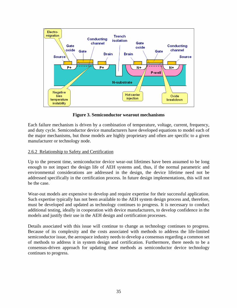
35
Figure 3. Semiconductor wearout mechanisms
Each failure mechanism is driven by a combination of temperature, voltage, current, frequency, and duty cycle. Semiconductor device manufacturers have developed equations to model each of the major mechanisms, but those models are highly proprietary and often are specific to a given manufacturer or technology node. 2.6.2 Relationship to Safety and Certification
Up to the present time, semiconductor device wear-out lifetimes have been assumed to be long enough to not impact the design life of AEH systems and, thus, if the normal parametric and environmental considerations are addressed in the design, the device lifetime need not be addressed specifically in the certification process. In future design implementations, this will not be the case. Wear-out models are expensive to develop and require expertise for their successful application. Such expertise typically has not been available to the AEH system design process and, therefore, must be developed and updated as technology continues to progress. It is necessary to conduct additional testing, ideally in cooperation with device manufacturers, to develop confidence in the models and justify their use in the AEH design and certification processes. Details associated with this issue will continue to change as technology continues to progress. Because of its complexity and the costs associated with methods to address the life-limited semiconductor issue, the aerospace industry needs to develop a consensus regarding a common set of methods to address it in system design and certification. Furthermore, there needs to be a consensus-driven approach for updating these methods as semiconductor device technology continues to progress.

36
2.6.3 Existing Activity
The models used by semiconductor device manufacturers are not normally available to the users of the devices. It is possible, however, to develop “generic” models based on published literature—this has been done by DfR Solutions, working under contract to AFE 71, supplement 1 [1, 2]. The models produced are shown in table 3. The work is continuing in AFE 83, which is developing spreadsheets containing “default” models that can be used by AEH system designers and certification specialists with a basic knowledge of the issue.
Table 3. Acceleration models
−∗
= 21
21
2
1
2
1 TTTT
kE
dd
dd
n
EM
a
eVV
ffAF
γ
−∗
−∗
= 21
21
21
21
TTTT
kE
VVVV
HCI
a
dsds
dsds
eeAFγ
−∗
= 21
21
2
1 TTTT
kE
gs
gsNBTI
a
eVV
AFγ
( )
( )
−+
−∗
+
+
=2
22
1
22
21
21
21
2
1 *
2
1 TTTTd
TTTTc
bTags
bTags
TDDB eVV
AF
In the early 2000s, some AEH manufacturers initiated discussion with some of the major commercial semiconductor device manufacturers, who indicated that they had information that would be useful to AEH users and would be willing to share such information if the proper vehicle for sharing such data, and incentives to do so, would be made available. In this regard, the aerospace industry published two documents [4, 5]. This effort produced no tangible results and the two documents currently do not adequately define the information needed to address this issue. AFE 71 initiated discussions with key semiconductor device manufacturers and semiconductor industry groups regarding the information needed from the device manufacturers to support AEH needs; these discussions are continuing in AFE 83. Aside from some very encouraging responses from a few semiconductor device manufacturers, no concrete results have yet been obtained on the scale necessary to support AEH needs. Based on the results of past efforts by AEH industries to communicate their needs to semiconductor device manufacturers, and on the relative unimportance of AEH customers to semiconductor device manufacturers, it is not likely that the current level of communication and data exchange between the two industries will satisfy all the needs of the AEH industries. These efforts will continue, but the most likely path for success in addressing this issue is for the AEH industries to develop, using their own generic models, based on the best technical information available. 2.6.4 Technology Weakness/Deficiency
Semiconductor technology is progressing at such a quick rate that it is difficult for AEH system designers and certification agencies to accommodate it. Because the issue of life-limited semiconductors is technically complex—and dynamic—the expertise to deal with it generally does not exist in the AEH industry.

37
2.6.5 Process Weakness/Deficiency
There currently is no consensus on a feasible set of methods to address the issue of life-limited semiconductor devices in the AEH system design and certification process. 2.6.6 Recommendations/Desired Outcome
The following “solution elements” need to be in place to address the limited-life semiconductor issue: • AEH System Design, Production, and Support—AEH manufacturers need to have access
to data and other information needed to address the limited-life semiconductor issue in the AEH system design, production, and support phases.
• AEH System Certification—Certification authorities need to have sufficient knowledge and information to evaluate applicants’ data submissions with regard to limited-life semiconductors; also, there needs to be adequate documentation to ensure that the certification process is conducted effectively and consistently for all AEH systems.
• AEH Procurement—AEH procurement documents, such as Specification Control Drawings (SCDs), Statements of Work, and other contract language documentation, need to include requirements to ensure that the life-limited semiconductor issue is addressed adequately by AEH manufacturers. If necessary, aerospace industry standards must be developed or revised for this purpose.
The AFE 75 PMC recommends that the International Electrotechnical Commission (IEC) TC107 [6] or SAE International’s (SAE) Avionics Process Management Committee (APMC) [7] develop standards to address life-limited semiconductor devices in AEH system design and that IEC and SAE consider producing a single document to avoid the inevitable divergence of two standards being produced. The AFE 75 PMC recommends that certification authorities and avionics system customers (e.g., the Department of Defense and platform integrators) adopt IEC TC 107 or SAE APMC committee standards after they are released. 2.6.7 References
1. Condra, L., Hillman, C., Redman, D., and Wyrwas, E., “Microcircuit Reliability Prediction Based on Physics of Failure Models,” IMAPS Advanced Technology Workshop on High Reliability for Military Applications, August 31, 2010.
2. Wyrwas, E.J. and Bernstein, J.B., “Quantitatively Analyzing the Performance of Integrated Circuits and Their Reliability,” IEEE Instrumentation & Measurement Magazine, February 2011, pp. 24–31.
3. Mesgarzadeh, B., Soderquist, I., and Alvandpour, A., “Reliability Challenges in Avionics due to Silicon Aging,” 15th IEEE International Symposium on Design and Diagnostics of Electronic Circuits and Systems, DDECS,” Tallinn, Estonia, April 18–20, 2012, pp. 342–347.
4. TechAmerica, GEIA-STD-0002-1, “Aerospace Qualified Electronic Component (AQEC) Requirements, Volume 1 – Integrated Circuits and Semiconductors,” August 1, 2005.

38
5. International Electrotechnical Commission/Technical Specification, IEC/TS 62564, “Process management for avionics – Aerospace qualified electronic components (AQEC) - Part 1: Integrated circuits and discrete semiconductors,” Edition 2.0, August 2011.
6. International Electrotechnical Commission (IEC) Technical Committee (TC) 107, “Process Management for Avionics,” http://www.iec.ch/dyn/www/f?p=103:7:0::::FSP_ORG_ID:1304 (accessed on 12/05/2014).
7. SAE International, “Avionics Process Management Committee” (APMC), http://www.sae.org/works/committeeHome.do?comtID=TEASSTCAPMC (accessed on 04/12/2014).
8. International Electrotechnical Commission/Technical Specification, IEC/TS 62239-1, “Process management for avionics - Management plan - Part 1: Preparation and maintenance of an electronic components management plan,” International Electrotechnical Commission, ed., Edition 1.0, July 2012.
9. Joint Electronic Device(s) Engineering Council Document, JESD 47 Revision 1, “Released for Stress-Test-Driven Qualification of Integrated Circuits,” July 2012.
10. Joint Electronic Device(s) Engineering Council Document, JEPP122G, “Failure Mechanisms and Models for Semiconductor Devices,” October 1, 2011.
2.6.8 Acronyms and Abbreviations
The following acronyms and abbreviations were used in section 2.6. nm Nanometers AEH Airborne electronic hardware AFE 71 Reliability prediction software AFE 83 Semiconductor reliability APMC Avionics Process Management Committee AQEC Aerospace qualified electronic components CMOS Complementary-metal-oxide-semiconductor DDECS Design and diagnostics of electronic circuits and systems DfR DfR Solutions EM Electromigration FPGAs Field-programmable Gate Arrays GEIA Government Electronics and Information Technology Association HCI Hot carrier injection IEC International Electrotechnical Commission IEEE Institute of Electrical and Electronics Engineers IMAPS International Microelectronics Assembly and Packaging Society JEDEC Joint Electronic Device Engineering Council JESD JEDEC Standard NBTI Negative bias temperature instability STD Standard TDDB Time dependent dielectric breakdown TC Technical Committee TS Technical Specification
39
2.7 OUTDATED RELIABILITY ASSESSMENT METHODS
2.7.1 Description of the Issue
Existing guidance for predicting the reliability of ADHP electronic systems is outdated and unmanaged. This can lead to inaccuracies in predictions and a variety of methodologies that interpret the available guidance. This applies to both custom and commercial off-the-shelf (COTS) electronics; however, COTS electronics are subject to the additional issue of avionics systems developers often not having a detailed knowledge of a COTS component or assembly. This can be hierarchical throughout the supply chain: subsystem suppliers may protect their intellectual property by supplying a “black box” while at the same time incorporating components for which they have incomplete knowledge of the detailed design. Thus, a set of reliability prediction methodologies is needed that (1) ensures consistent application of analyses, (2) is broadly adopted, (3) provides improved accuracy, (4) is comprehensive enough to maintain consistency for a broad range of avionics technologies that are integrated into systems, (5) is maintainable so as to keep pace with changes in commercial technologies, and (6) is applicable to both custom and COTS components. In the 1950s, electronics reliability models were developed and standardized by the Department of Defense (DoD) through the analysis of historical failure data. In 1961, the first edition of the military handbook, “Reliability Prediction of Electronic Equipment” MIL-HDBK-217 [1], was published, providing a basic reliability analysis tool that is still in use today (although it has undergone several revisions). In 1994, U.S. Secretary of Defense William Perry published his pivotal memorandum titled “Specifications & Standards - A New Way of Doing Business” [2]. This memo, and the changes in military acquisitions that followed, caused many military standards to be canceled in favor of commercial standards and practices. A consequence of this memo is that DoD stopped updating MIL-HDBK-217 and started looking to industry organizations to provide updated reliability prediction methods. The most recent revision of MIL-HDBK-217 is dated February 28, 1995 and, although clearly obsolete, some of the basic assumptions used for electronic components are still applicable. For this reason, a complete revision of every model in the handbook may not be necessary or cost-effective. It is important, however, to update some models—and perhaps the framework of the document itself—to accommodate the rapidly changing electronics supply chain, especially with respect to COTS components, assemblies, and equipment. A major weakness of MIL-HDBL-217 and other “bottom-up” reliability prediction methods is their total focus on part failures as causes of system failures, neglecting other causes, such as system design, maintenance practices, and operational misuse. In contrast, “Guidelines for Preparing Reliability Assessment Plans for Electronic Engine Controls,” SAE ARP 5890A [3], takes a “top-down” approach in which reliability data from a similar predecessor product in a similar application are analyzed to produce a system reliability assessment. If no sufficiently similar predecessor product is found, then the process uses successively lower-level assemblies, sub-assemblies, or components until some similar predecessor product is found. If no such lower-level predecessor products are found, the process becomes a “bottom-up” approach.

40
2.7.2 Relationship to Safety and Certification
Reliability predictions have been used by AEH system producers and users for many purposes, including system design, system architecture, reliability analysis, trade studies, safety analysis, availability analysis, spares planning, redundancy modeling, failure modes and effects analysis (FMEA), scheduled maintenance planning, and product warrantees and guarantees. Typical safety and certification analyses involve system-level methods such as fault tree analysis (FTA), FMEA, and failure mode effects and criticality analysis (FMECA). Most of these methods work with inputs regarding failure rates derived, if possible, from in-service experience. In view of today’s rapidly changing component technologies, it is unrealistic to expect that in-service data will be available in the timely manner required for certification and safety analysis of new systems. 2.7.3 Existing Activity
The Defense Standardization Program Office (DSPO), working through the Naval Surface Warfare Center (NSWC) Crane Division, is the preparing and maintenance authority for MIL-HDBK-217. In 2008, the NSWC Crane Division launched an effort to revise MIL-HDBK-217 and convened an industry WG to review and propose changes to the handbook. The initial phase of this effort was to provide an update to key reliability parameters but not include new models. It was anticipated that future phases of the NSWC Crane Division effort would develop a fundamentally new approach using physics of failure modeling methods. The DSPO also sponsored aerospace industry collaborative research through the Aerospace Vehicle Systems Institute (AVSI). Much of this research has been focused on mitigating the effects of atmospheric radiation and understanding and mitigating the effects on microcircuit reliability and service life, as semiconductor technology progresses below 100-nanometer feature sizes. This research resulted in advances in physics of failure-based modeling of semiconductor wear-out mechanisms and has produced results that should be captured in ADHP system reliability analyses. Subsequent AVSI research projects considered the need for a broader set of integrated issues than just the incorporation of semiconductor physics of failure models in the existing reliability guidance. These efforts led to an industry consensus reliability roadmap [4] that identified a number of perceived gaps in existing reliability methodologies. The features desired in an integrated set of reliability prediction methodologies were identified and prioritized by a broad representation of the U.S. aerospace industry using a quality functional deployment formalism to ensure that multiple perspectives were represented in the resulting roadmap. This roadmap has been presented at a number of conferences to continue with a representative, consensus-based approach for developing a broadly adopted, coherent, accurate, and integrated set of reliability-prediction methodologies for AEH suppliers and integrators. 2.7.4 Technology Weakness/Deficiency
The currently used methods for AEH system reliability predictions are outdated and inaccurate. Because of the long development cycle times for AEH compared to those for commercial electronics, it is increasingly unrealistic to accumulate sufficient in-service data in time to have it

41
available for the design and certification process. This is especially true of the commonly used “bottom-up” methods. 2.7.5 Process Weakness/Deficiency
Despite the widespread distrust of currently used methods, there is no consensus regarding any type of replacement for them. This has led to cynicism about any reliability prediction process or data, and it is often concluded there is no discernible process or data for a given product or program. 2.7.6 Recommendations /Desired Outcome
A current AVSI Project (AFE 80) is continuing the maintenance and update of the reliability roadmap. This project supports other projects with a detailed framework for the reliability modeling approach, including many of the features of the roadmap that are common to all reliability modeling approaches, such as common standards for establishing models, application of models, testing, data collection, and validation. AFE 80 explores ways to assure periodic maintenance and update of the models. In addition, AFE 80 investigates the feasibility of, and establishes ground rules for, implementing a reliability prediction methodology electronically rather than as a static, published document. This documented framework includes:
1. Establishing new reliability models a. Standards for the progress of subprojects b. Typical progression of tasks c. Common rules for engaging and proposing a model d. Checklist for subproject launch
2. Application of reliability models a. Common rules for using models b. Calibration c. Levels of detail needed for different applications d. Criteria for modeling environmental effects e. Address complexities in the natural environment
3. Validation a. Define what it means to be “validated” (versus “demonstrated”) b. Standards for testing and analyses c. How much field data is enough (agree on statistical tests)?
4. Mechanism for review and update of models a. Ongoing maintenance of models b. Ground rules for periodic updates c. Use of field data
5. Electronic-based methodology a. Issues to resolve (e.g., configuration control) to achieve an accelerated (over paper
publication) but still deliberate process b. Vetting of new contributions c. Processes for updating

42
d. Usage standards, user policy e. Defaults
The AFE 80 work described above is focused on the “bottom-up” approach. As noted earlier, SAE ARP 5890A takes a “top-down” approach and is being used successfully by a number of avionics manufacturers and users, particularly those in the electronic engine controls segment of the industry (ARP 5890A was published and is maintained by SAE committee E-36, electronic engine controls). Because of its inherently more-comprehensive and -logical approach to reliability assessment, ARP 5890A deserves greater consideration by a wider range of avionics manufacturers and customers and also for use in the certification process. Any solution to the inadequacy of existing reliability guidance and methodologies must provide incentives for ADHP stakeholders across the globe to work together to: 1. Provide a focus organization—preferably a standards organization, such as International
Electrotechnical Commission (IEC) or SAE—that includes all stakeholders to provide visibility into all reliability related work for the ADHP industries, including standards publication and maintenance and related research.
2. Work with ADHP customers and regulatory agencies to provide the incentives for manufacturers and suppliers of ADHP systems to develop and use consistent reliability methods.
3. Synchronize reliability methods on a global basis. 4. Encourage ADHP stakeholders to prioritize improvements in accuracy and consistency to
effect cost savings and improved designs. 5. Advise reliability engineers at all levels of the ADHP supply chain to adopt best practices
in implementing the reliability prediction methodologies. The AFE 75 PMC recommends the use of ARP-5890A for reliability assessment and certification process. The FAA’s Advisory Circular (AC) 20-157, “How To Prepare a Reliability Assessment Plan for Aircraft Systems and Equipment” [5] refers to ARP-5890. The AFE 75 PMC recommends that the FAA update AC 20-157 to recognize ARP-5890A. The AFE 75 PMC further recommends the ownership of the document be transferred from SAE Committee E-36 to SAE APMC [6]. 2.7.7 References
1. Military Handbook, MIL HDBK 217 F Military Handbook, Reliability Prediction of Electronic Equipment notice 2, February 28, 1995.
2. Perry, William, “Specifications & Standards - A New Way of Doing Business,” June 29, 1994, http://www.sae.org/standardsdev/military/milperry.htm (accessed on 12/08/2014).
3. SAE International, SAE ARP 5890A, “Guidelines for Preparing Reliability Assessment Plans for Electronic Engine Controls,” February 1, 2011.
4. “Reliability Roadmap and Proposed Projects,” AFE74S1 Final Report, Aerospace Vehicle Systems Institute, May 22, 2012 (not currently available to the public).
5. FAA Advisory Circular AC 20-157, “How to Prepare a Reliability Assessment Plans for Aircraft Systems and Equipment,” January 19, 2007.

43
6. SAE, International, “APMC – Avionics Process Management Committee,” http://www.sae.org/works/committeeHome.do?comtID=TEASSTCAPMC (accessed on 12/08/2014).
2.7.8 Acronyms
The following acronyms were used in section 2.7. AC Advisory Circular ADHP Aerospace, defense, and high performance AEH Airborne electronic hardware AFE Authorization for Expenditure AFE 80 Integrated reliability project APMC Avionics Process Management Committee ARP Aeronautical recommended practice AVSI Aerospace Vehicle System Institute COTS Commercial off-the-shelf DoD Department of Defense DSPO Defense Standardization Program Office FMEA Failure mode effects analysis FMECA Failure mode effects and criticality analysis FTA Fault tree analysis HDBK Handbook IEC International Electrotechnical Commission MIL Military NSWC Naval Surface Warfare Center

44
2.8 TRANSITION TO LEAD-FREE ELECTRONICS
The transition to a lead-free environment is clearly among the issues and threats that the AFE 75 Project has considered as potentially impacting safety. The transition to lead-free electronics throughout the globe has resulted in a serious increase in the threat to aviation electronics reliability, and it is difficult, if not impossible, to quantify the risk. To ensure that a system meets of all its safety and reliability requirements, potential system failures due to the transition to lead-free electronics should be considered as an element of the design. 2.8.1 Description of the Issue
In 2002, the European Union issued a directive (EU Directive 2002/95/EC) [1]) requiring that new electrical and electronics equipment and systems placed on the market after July 1, 2006 not contain lead (Pb) or other environmentally hazardous materials. In response to this directive, and legislation resulting from it, the global electronics industry is undergoing a transition from tin-lead (SnPb) to lead-free (Pb-free) assembly alloys and termination finishes. Although aerospace generally has been excluded from the directive and legislation, it has been “swept along” as the global electronics supply base makes the transition and, therefore, must accommodate the use of lead-free electronics. Traditionally, lead has been used as surface plating for soldering purposes (e.g., SnPb solder alloys) on discrete electrical and electronics components, including integrated circuits, semiconductors, capacitors, resistors, and other electronic circuitry. Currently, the largest volume of lead in many of these electronic assemblies is in the Sn-Pb eutectic and near-eutectic alloys used in wiring, printed circuit board assemblies, wiring harnesses, and electrical and electronic equipment and systems. Aerospace electronics, with their unique environmental and qualification requirements, is impacted in the following five key areas: 1. Solder Joint Reliability/Line Replaceable Units (LRU) Qualification: No consensus currently exists regarding assurance of reliability of solder joints made with the various lead-free assembly alloys commonly used in electronics assemblies. This is further complicated because a variety of alloys are currently in use, and new ones are being introduced as development continues. Aerospace electronics and electrical products can be critical elements in the safety of the aircraft. In addition, material changes in LRUs that may affect the reliability of the product can require re-qualification of the product. 2. Tin Whisker Susceptibility: In the near-term, particularly during the transition to lead-free electronics, one of the more significant threats to proper operation is tin whisker susceptibility. A common replacement for lead in electronic-component termination finishes is pure Sn, which is known to produce tin whiskers. Tin whiskers are conductive growths that can cause electrical shorts in aerospace

45
electronics equipment. At present, tin whisker growth is not clearly understood and no known solutions exist to completely preclude this phenomenon. 3. Maintenance/Repair Methodology: As the transition to lead-free electronics continues, it is vitally important to maintain proper maintenance procedures and materials. As of this writing, there is no single or universal material solution for the replacement of Sn-Pb solder and finish. In addition, at this point, it is not clear that the mixing of various materials results in a reliable solder joint. The manufacturer must clearly call out maintenance and repair methodologies so that all maintenance shops can follow proper steps in their processes. 4. Configuration Control: One of the more difficult issues identified at this time by the above-referenced WGs is that of configuration control. As the component manufacturers are transitioning to lead-free finishes, they are not consistently, if at all, identifying the new finish materials. This has led to a configuration-control difficulty for the aerospace industry. Aerospace has rather strict policies and procedures for configuration control, and these must be adhered to for part termination and assembly alloys. 5. Component Availability: The availability of components, as related to the transition to lead-free electrical/electronics components, appears to be a primary link to the configuration control issue. It is not obvious that the transition to lead-free electronics will in itself cause component obsolescence, but it will lead to unavailability of Sn-Pb based components. 2.8.2 Relationship to Safety and Certification
Methods to address the lead-free environment in the AEH design, development, and certification processes should be developed and incorporated into those processes. The methods should include tests, analyses, and other processes to determine the potential impact on the safety and airworthiness of the system. The certification process should be modified to assess the use and effectiveness of the methods. To ensure a system meets all its safety and reliability requirements, potential system failures resulting from the lead-free environment need to be considered as an element of the design. Test protocols that have been traditionally used in qualifications tests may or may not be appropriate protocols to determine if the new materials will withstand rigorous aerospace and avionics environments. Product performance needs to be reviewed periodically and supported by root cause analysis of any field failures to validate or improve test protocols. Pb-free solders and finishes may decrease the reliability of systems or subsystems. The following may impact safety and system performance:

46
• Pb-free solders may be common in commercial off-the-shelf (COTS) piece parts. • SnPb solders and finishes on assembly piece parts may be difficult to procure. • SnPb solders and finishes may not be available regardless of contract or specification. • SnPb versus Pb-free piece parts may be difficult to identify in pre-assembled subsystems. • System production and maintenance personnel may inadvertently mix potentially
incompatible SnPb and Pb-free solders.
2.8.3 Existing Activity
The Lead-Free Electronics in Aerospace Project WG (LEAP WG) [2] was formed in 2004, sponsored jointly by the Aerospace Industries Association (AIA), Avionics Maintenance Conference (AMC), and Government Electronics and Information Technology Association (GEIA). The task of the LEAP WG was to address aerospace issues related to the global elimination of Pb from electrical and electronic equipment placed on the market after July 1, 2006. The LEAP WG was superseded by the Pb-free Electronics Risk Management (PERM) Consortium, sponsored by the Institute for Interconnecting and Packaging Electronic Circuits (IPC) [3]. The major LEAP-PERM deliverables are standards and handbooks designed to assist and guide industry in the transition to Pb-free solder and finishes. These documents are currently the best resource for guidance in the transition to Pb-free avionics and are listed in table 4. The second reference number shown in the second column of table 4 for each GEIA document is a corresponding IEC reference.

47
Table 4. Standards and handbooks for lead-free transition
GEIA-STD-0005-1 Performance Standard for Aerospace and High Performance Electronic Systems Containing Lead-Free Solder [4][5]
Used by aerospace electronic system “customers” to communicate requirements to aerospace electronic system “suppliers”
GEIA-STD-0005-2 Standard for Mitigating the Effects of Tin Whiskers in Aerospace in High-Performance Electronic Systems [6][7]
Used by electronic system “suppliers” as a guide in the design and evaluation of designs that need to be robust to the effects of tin whiskers
GEIA-STD-0005-3 Performance Testing for Aerospace and High-Performance Electronic Interconnects Containing Lead-Free Solder and Finishes [8][9]
Used by aerospace electronic system “suppliers” to develop reliability test methods and interpret results for input to analyses
GEIA-HB-0005-1 Program Management/Systems Engineering Guidelines for Managing the Transition to Lead-Free Electronics [10][11]
Used by program managers to address all issues related to lead-free electronics (e.g., logistics, warranty, design, production, contracts, procurement, etc.)
GEIA-HB-0005-2 Technical Guidelines for Aerospace and High Performance Electronic Systems Containing Lead-Free Solder and Finishes [12][13]
Used by aerospace electronic system “suppliers” to select and use lead-free solder alloys, other materials, and processes. It may include specific solutions, lessons learned, test results, and data, etc.
GEIA-HB-0005-3 Repair and Rework of Aerospace and High-Performance Electronic Systems Containing Lead-Free Solder [14][15]
Used by technicians and the planners in the repair and rework end of the life cycle to assure that the proper techniques are followed
HB = handbook In 2009, the lead-free Manhattan Project convened a group of subject-matter experts from aerospace and defense to identify the key risks associated with lead-free solder in high-reliability and safety-critical systems. The cost to close the knowledge gaps for using lead-free electronics in these applications was estimated at $105 million [16, 17]. 2.8.4 Technology Weakness/Deficiency
To date, no single Pb-free alloy is a drop-in replacement for the SnPb eutectic alloys in widespread use in the electronic and electrical industry over the last 50 years. Eutectic Sn-Pb (melting point 183° C) and near-eutectic alloys have been predominantly used in electronics/electrical assemblies. Many of the proposed alternative materials have higher melting points than current eutectic Sn-Pb, whereas some of the lower-temperature materials will not be able to withstand the extreme operating environments encountered in aerospace and aviation applications. Most of the commonly used alloys require higher processing temperatures that can result in damage to the printed circuit board or components. Reliability testing methods for Pb-free alloys are still being developed. Results from thermal cycling reliability testing conducted to date comparing Pb-free to SnPb alloys have yielded inconclusive results for aerospace applications. The results have shown that some alloys in mild environmental conditions are more reliable, whereas the same alloys are much less reliable in harsher environments. Thus, depending upon the Pb-free alloy type and the application, tests have shown that their useful life may be shortened because of greater fatigue than the SnPb alloy for which it is substituted. In addition to the lack of consensus from Pb-free thermal cycling tests, there is little vibration and shock modeling or durability test data available for the Pb-free alloys. Another risk associated with the use of Pb-free components, especially on printed circuit boards, is the need for processing temperatures, which exacerbate the coefficient of thermal expansion

48
(CTE) mismatches, which could reduce component service life in comparison to SnPb components. Another risk is that Pb contamination can negatively influence the properties of Pb-free solders. For example, if a printed circuit board (PCB) was originally manufactured with SnPb solder and, during a repair operation, the SnPb solder was not adequately removed, then the introduction of Pb-free solder with certain alloys may result in a flawed solder joint. 2.8.5 Process Weakness/Deficiency
Some avionics products already contain components with pure Sn termination finishes and other Pb-free finishes. So far, there have been no identified failures related to the introduction of these Pb-free finishes. However, it is acknowledged that the test protocols traditionally used in these qualifications tests may or may not be appropriate protocols for determining if the new materials will withstand the rigorous aerospace and avionics environments. 2.8.6 Recommendations/Desired Outcome
The research to address the issues raised by the Lead-free Manhattan project [16, 17] has not been funded. The AFE 75 PMC supports the efforts of PERM and others to obtain this funding without taking the lead in the effort. The AFE 75 PMC endorses the cited references published by IEC TC107 [18] and SAE APMC [19] and recommends that the International Electrotechnical Commission (IEC) and SAE International consider producing a single set of documents pertaining to the development of electronics that require Pb-free solder be used. The AFE 75 PMC recommends that certification authorities and avionics system customers (e.g., the Department of Defense and platform integrators) adopt IEC TC 107 or the SAE Avionics Process Management Committee standard for Pb-free electronics. 2.8.7 References
1. Directive 2002/95/EC of the European Parliament and of the Council, “The Restriction of the use of certain Hazardous Substances in electrical and electronic equipment,” January 27, 2003.
2. Lead-free Electronics in Aerospace Project (Leap), Working Group (WG), Aerospace Industries Association (AIA), the Avionics Maintenance Conference (AMC), and the Government Electronics and Information Technology Associates, http://www.aia-aerospace.org/assets/wp_leap-wg_1106.pdf (accessed on 12/08/2014).
3. Pb-free Electronics Risk Management (PERM) Consortium, http://www.ipcoutlook.org/mart/51458F.shtml (accessed on 12/08/2014).
4. TechAmerica Standard, GEIA-STD-0005-1-A, “Performance Standard for Aerospace and High Performance Electronic Systems Containing Lead-free Solder,” March 1, 2012.
5. IEC/TS 62647-1 edition 1.0, “Process management for avionics - Aerospace and defense electronic systems containing lead-free solder - Part 1: Preparation for a lead-free control plan,” August 2012.
6. TechAmerica Standard, GEIA-STD-0005-2A, “Standard for Mitigating the Effects of Tin Whiskers in Aerospace In High Performance Electronic Systems,” May 1, 2012.

49
7. IEC/TS 62647-2 edition 1.0, “Process management for avionics - Aerospace and defense electronic systems containing lead-free solder - Part 2: Mitigation of deleterious effects of tin,” November 2012.
8. TechAmerica Standard, GEIA-STD-0005-3-A, “Performance Testing for Aerospace and High Performance Electronic Interconnects Containing PB-free Solder and Finishes,” March 1, 2012.
9. International Electrotechnical Commission/Publically Available Specification, IEC/PAS 62647-3 edition 1.0, “Process management for avionics - Aerospace and defense electronic systems containing lead-free solder - Part 3: Performance testing for systems containing lead-free solder and finishes,” July 2011.
10. TechAmerica Handbook, GEIA-HB-0005-1, “Program Management/Systems Engineering Guidelines for Managing the Transition to Lead-Free Electronics,” June 20, 2006.
11. International Electrotechnical Commission/Publically Available Specification, IEC/PAS 62647-21 edition 1.0, “Process management for avionics - Aerospace and defense electronic systems containing lead-free solder - Part 21: Program management - Systems engineering guidelines for managing the transition to lead-free electronics,” July 2011.
12. TechAmerica Handbook, GEIA-HB-0005-2, “Technical Guidelines for Aerospace and High Performance Electronic Systems Containing Lead-Free Solder and Finishes,” November 2007.
13. International Electrotechnical Commission/Publically Available Specification, IEC/PAS 62647-22 edition 1.0, “TC/SC 107, Process management for avionics - Aerospace and defense electronic systems containing lead-free solder - Part 22: Technical guidelines,” July 2011.
14. TechAmerica Handbook, GEIA-HB-0005-3, “Rework/Repair Handbook to Address the Implications of Lead-Free Electronics and Mixed Assemblies in Aerospace and High Performance Electronic Systems,” September 1, 2008.
15. International Electrotechnical Commission/Publically Available Specification, IEC/PAS 62647-23 edition 1.0, “Process management for avionics - Aerospace and defense electronic systems containing lead-free solder - Part 23: Rework and repair guidance to address the implications of lead-free electronics and mixed assemblies,” July 2011.
16. “The Lead-free Electronics Manhattan Project Reports,” Phase 1, U.S. Government Contract No. N00014-08-D-0758, Benchmark Center of Excellence, ACI Technologies, 2009.
17. “The Lead-free Electronics Manhattan Project Reports,” Phase 2, U.S. Government Contract No. N00014-08-D-0758, Benchmark Center of Excellence, ACI Technologies, 2010.
18. International Electrotechnical Commission (IEC) Technical Committee (TC) 107, “Process Management for Avionics,” http://www.iec.ch/dyn/www/f?p=103:7:0::::FSP_ORG_ID:1304, (accessed on 12/08/2014).
19. SAE International, “APMC – Avionics Process Management Committee,” http://www.sae.org/works/committeeHome.do?comtID=TEASSTCAPMC (accessed on 12/08/2014).
2.8.8 Acronyms and Abbreviations
The following acronyms and abbreviations were used in section 2.8.
50
AEH Airborne electronic hardware AFE Authorization for Expenditure AIA Aerospace Industries Association AMC Avionics Maintenance Conference COTS Commercial off-the-shelf CTE Coefficient of thermal expansion EC European Council EU European Union GEIA Government Electronics and Information Technology Association HB Handbook IEC International Electrotechnical Commission IPC Institute for Interconnecting and Packaging Electronic Circuits LEAP Lead-Free Electronics in Aerospace Project LRU Line replaceable unit Pb Lead PAS Publically available specifications PCB Printed circuit board PERM Pb-free electronics risk management SnPb Tin-lead STD Standard TC Technical Committee TS Technical Specification WG Working group 2.9 AVAILABILITY AND UPDATES OF ERRATA
2.9.1 Description of the Issue
Complex commercial-off-the-shelf (COTS) components can have unseen functional behavior that may not be revealed until their actual usage in industry. As a result, component manufacturers need to notify their customers of issues and provide suggested workarounds by publishing an errata document. A component’s well-maintained errata document allows a new product design to capitalize on the previous industry usage of a complex COTS component. Most processor manufacturers have a well-defined errata practice and format that has evolved over years of development. This same approach is expected for other types of complex COTS components. Because there is no guiding standard for what constitutes a good errata document, this section will be used to establish expectations for a complex COTS component’s errata using existing processor errata as a guide. 2.9.2 Relationship to Safety and Certification
A regularly updated errata document for a complex COTS component is important for the safe operation of avionics equipment because it notifies users of bugs and fixes found by other users. Errata updates and the notification process continue well after the avionics system is in production and in service. For example, errata updates for a processor typically continue for years after the part is productionized.

51
2.9.3 Existing Activity
The European Aviation Safety Agency (EASA) Certification Memorandum (EASA CM – SWCEH – 001) - Section 9.3.4 [1] mentions that the applicant should show how the component manufacturer captures, maintains, and publishes errata. It also wants to see trending evidence of a decrease in rate of occurrence of new errata updates over time (to establish component maturity). 2.9.4 Technology Weakness/Deficiency
Whenever a COTS component becomes so complex that it cannot be completely tested before production, it also uses customer in-use validation. These types of components should have an errata policy to support and track this continued validation. In the past, mainly processors fell into this group, but now many other complex COTS components should be included (and in many cases they already have errata being published). Peripheral Component Interconnect Express (PCIe) switches, Serial Rapid Input/Output (sRIO) switches, Universal Serial Bus (USB) or Secure Data (SD) Card controller chips, and Ethernet Media Access Controls (MACs) are examples of complex COTS components that need an errata document. 2.9.5 Process Weakness/Deficiency
It is obvious that processors need an errata document, but when do other COTS components become complex enough to require a published and regularly updated errata? Further, there is no formal guidance on what constitutes a well written and complete errata document. There should be a list of minimum content necessary in a published errata document. The frequency of updates to the errata document and how long it takes before a known issue gets incorporated into the next errata revision are also important in assessing the errata of a COTS component. 2.9.6 Recommendations/Desired Outcome
The AFE 75 PMC recommends a revision to SAE EIA-4899 [2] and IEC/TS 62239-1 [3] standards. The revision should contain an evaluation of the quality of the errata document as discussed in the tables below. Table 5 shows the expected content of an errata document and the associated questions, whereas table 6 shows the questions we recommend be addressed when a given complex COTS component does not have an errata document.
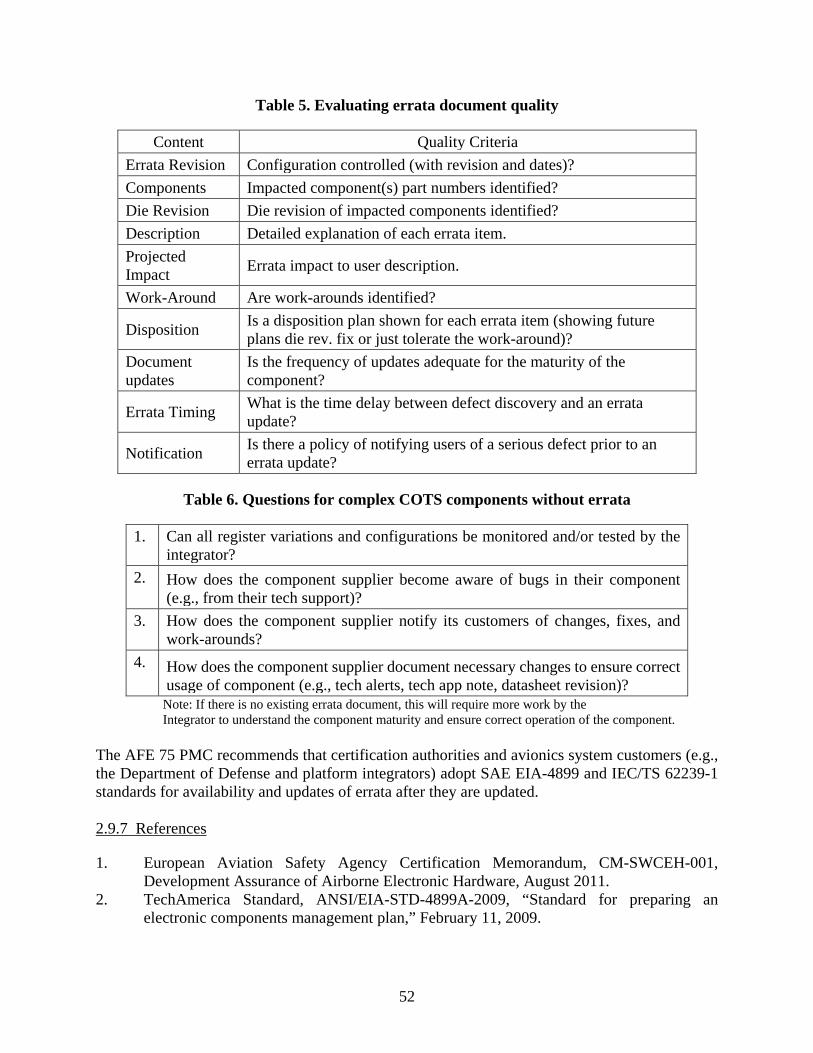
52
Table 5. Evaluating errata document quality
Content Quality Criteria Errata Revision Configuration controlled (with revision and dates)? Components Impacted component(s) part numbers identified? Die Revision Die revision of impacted components identified? Description Detailed explanation of each errata item. Projected Impact Errata impact to user description.
Work-Around Are work-arounds identified?
Disposition Is a disposition plan shown for each errata item (showing future plans die rev. fix or just tolerate the work-around)?
Document updates
Is the frequency of updates adequate for the maturity of the component?
Errata Timing What is the time delay between defect discovery and an errata update?
Notification Is there a policy of notifying users of a serious defect prior to an errata update?
Table 6. Questions for complex COTS components without errata
1. Can all register variations and configurations be monitored and/or tested by the integrator?
2. How does the component supplier become aware of bugs in their component (e.g., from their tech support)?
3. How does the component supplier notify its customers of changes, fixes, and work-arounds?
4. How does the component supplier document necessary changes to ensure correct usage of component (e.g., tech alerts, tech app note, datasheet revision)?
Note: If there is no existing errata document, this will require more work by the Integrator to understand the component maturity and ensure correct operation of the component.
The AFE 75 PMC recommends that certification authorities and avionics system customers (e.g., the Department of Defense and platform integrators) adopt SAE EIA-4899 and IEC/TS 62239-1 standards for availability and updates of errata after they are updated. 2.9.7 References
1. European Aviation Safety Agency Certification Memorandum, CM-SWCEH-001, Development Assurance of Airborne Electronic Hardware, August 2011.
2. TechAmerica Standard, ANSI/EIA-STD-4899A-2009, “Standard for preparing an electronic components management plan,” February 11, 2009.

53
3. International Electrotechnical Commission/Technical Specification, IEC/TS 62239-1, “Process management for avionics - management plan - Part 1: Preparation and maintenance of an electronic components management plan,” International Electrotechnical Commission, ed., Edition 1.0, July 2012.
2.9.8 Acronyms and Abbreviations
The following acronyms and abbreviations were used in section 2.9. ANSI American National Standards Institute CEH Complex Electronic Hardware CM Certification Memorandum COTS Commercial off-the-shelf EASA European Aviation Safety Agency EIA Energy Information Administration IEC International Electrotechnical Commission MAC Media access control PCIe Peripheral Component Interconnect Express SD Secure data sRIO Serial rapid input/output STD Standard SW Software TS Technical Specification USB Universal serial bus
2.10 COUNTERFEIT ELECTRONIC PARTS Manufacturing technologies are increasingly advanced and standardized as globalization of all markets continues. As a result, the opportunities and potential rewards for counterfeit items in all markets has increased. The risks associated with counterfeiting include (1) risk to life and safety for those who depend on a product that may include a counterfeit part, (2) loss of revenue and damage to the reputation of a manufacturer whose products are counterfeited, and (3) financial loss to the purchaser or user of a counterfeit part. All of these risks, and others, may be present in AEH, but the first one detailed is clearly of most concern. 2.10.1 Counterfeit Parts Issue Details
Of all the items that may be counterfeited, electronics parts are among the most difficult to deal with: • They are often difficult to detect without expensive and complex test equipment. • They may perform adequately until certain stresses are applied at critical stages of
operation. • Their designs and production processes can change rapidly, and COTS components are
constantly being revised (e.g., dies shrink, or the processes are being updated, or the fabrication, assembly, and tests are being shifted from one location to another). All this noted churning provides an opportunity for counterfeiters to exact their trouble making.
54
• They are typically used in very small volumes for any given application, and they often pass through many “links” in a supply chain beyond the control and visibility of the AEH user
The counterfeit issue includes purchasing, quality, and engineering aspects. The quality aspect is focused on detection and disposition of counterfeit parts. The purchasing aspect is focused on avoidance of counterfeit parts. If electronic parts are purchased from the original component manufacturer (OCM) or from an authorized distributor, the risk of receiving a counterfeit part is low; if not, the risk can be very high. The engineering aspect includes steps to analyze and mitigate risks in the application. Often, because of obsolescence or other shortage situations, it is necessary to procure electronic parts from sources other than OCMs or authorized distributors. In such cases, it is necessary for engineering to conduct application-specific risk analyses. For applications that are critical for performance and safety, the cost to evaluate the risk and minimize the impact of a potential counterfeit part may be easier to justify than it is in less-critical applications. 2.10.2 Relationship to Safety and Certification
Almost all AEH systems are highly integrated and technically complex: • They must operate successfully for long periods of time (often decades) under highly
stressful conditions • The consequences of failure include loss of life and risk to national security • They are subject to extremely high financial impact for any failure The electronic parts used in AEH systems include memories and logic components with billions of transistors. They are almost always designed and produced for target markets other than AEH and, therefore, are not evaluated thoroughly by the manufacturer for any AEH applications. It may be possible for counterfeit parts to operate without system failure until the system is required to operate in certain ways or under certain environmental conditions; when either of these occurs, the system may fail. Therefore, it is often difficult to determine the impact of an undetected counterfeit part in the AEH design and certification stage. The costs to detect, analyze, and mitigate the risks of counterfeit parts can vary widely, so the AEH community must have consensus on the methods, processes, and data to be used in the certification process with respect to the risk of counterfeit electronic parts and disposition of such parts when detected. 2.10.3 Existing Activity
In recent years, the issue of counterfeit parts has been the subject of considerable attention in the commercial and military aerospace industries and in other similar industries. The U.S. Government Accountability Office summarized the issue in its report to the Senate Armed Services Committee in 2012 [1] and the U.S. Department of Commerce published the results of a counterfeit parts assessment in 2009 [2]. The U.S. Congress has addressed counterfeit parts in its 2013 National
55
Defense Authorization Act [3]. The European Aviation Safety Agency (EASA) has issued a safety information bulletin regarding counterfeit parts [4]. Aerospace integrators, avionics manufacturers, and operators have conducted many meetings and seminars and published information related to counterfeit electronic parts. The standards organizations also have been active, and references [5–11] are representative of their work. The standard that is most widely used by the AEH industries to address counterfeit parts is SAE AS5553A [8], which is a product of a large and widely ranging list of aerospace participants. It is currently undergoing revision. Although it addresses the quality, purchasing, and engineering aspects of the counterfeit parts issue, its emphasis is clearly on quality and purchasing and less on engineering. Therefore, there may be a need for further standards work to address engineering issues. A major task of the Aerospace Vehicle System Institute’s (AVSI) AFE 75 is to evaluate the large volume of information that has been generated about counterfeit electronic parts and published in a wide range of fora, then extract what is useful for safety and certification. There currently is no recognized AEH organization that is responsible for this task. 2.10.4 Technology Weakness/Deficiency
In a sense, there is no major technology weakness because the counterfeit parts issue is simply the result of untrustworthy activities on the part of those individuals and organizations that have chosen to deceive their customers and violate laws. In another sense, however, the technology weakness is our limited ability to detect counterfeit parts in all their forms and variations and develop countermeasures to make counterfeiting more difficult. Considerable research is being done in these areas, and progress is being made. However, counterfeiters also continue to develop their methods and it will always be a struggle for those who are trying to thwart them. 2.10.5 Process Weakness/Deficiency
The process weakness, or deficiency, is in our as yet unachieved consensus of how to conduct application-specific risk analyses for suspect counterfeit parts and how to evaluate such analyses for the certification process. 2.10.6 Recommendation/Desired Outcome
Of all the industry standards referenced in this report for mitigating the effects of counterfeit electronic parts, SAE AS5553 [8] and SAE AS6462 [9] are widely used and referenced by producers and users of AEH. The AFE 75 PMC acknowledges the growing consensus for using SAE AS5553 and AS6462 as the baseline requirement for certification with respect to counterfeit electronic parts. The AFE 75 PMC recommends that certification authorities and avionics system customers (e.g., the Department of Defense, platform integrators, and equipment developers) adopt SAE AS5553 and SAE AS6462 standards.

56
2.10.7 References
1. United States Government Accountability Office Report to the Committee on Armed Services, U.S. Senate, “DoD Supply Chain – Suspect Counterfeit Electronic Parts Can Be Found on Internet Purchasing Platforms,” GAO-12-375, February 2012.
2. United States Department of Commerce, Bureau of Industry and Security, Office of Technology Evaluation, “Defense Industrial Base Assessment: Counterfeit Electronics,” November 2009.
3. “National Defense Authorization Act for Fiscal Year 2013,” 112th Congress, 2nd Session, H.R. 4310.
4. European Aviation Safety Agency Safety Information Bulletin, SIB 2011-27, “Suspect (Bogus - Counterfeit) Integrated Circuits,” November 18, 2011.
5. International Electrotechnical Commission/Publically Available Specification, IEC/PAS 62668-1, “Process management for avionics – Counterfeit prevention – Part 1: Avoiding the use of counterfeit, fraudulent and recycled electronic components,” Edition 1.0, May 2012.
6. TechAmerica Technical Bulletin, TB-0003, “Counterfeit Parts & Materials Risk Mitigation,” February 2009.
7. SAE International, SAE AS6174, “Counterfeit Materiel; Assuring Acquisition of Authentic and Conforming Material,” May 2012.
8. SAE International, SAE AS5553A, “Counterfeit Electronic Parts; Avoidance, Detection, Mitigation, and Disposition,” January 2013.
9. SAE International, SAE AS6462, “Counterfeit Electronic Parts; Avoidance, Detection, Mitigation, and Disposition Verification Criteria,” November 2012.
10. SAE International, “Fraudulent/Counterfeit Electronic Parts; Tool for Risk Assessment of Distributors,” December 2011.
2.10.8 Abbreviations and Acronyms
The following abbreviations and acronyms were used in section 2.10. U.S. United States AEH Airborne electronic hardware AFE Authorization for expenditure AS Aerospace Standard AVSI Aerospace Vehicle System Institute DoD Department of Defense EASA European Aviation Safety Agency GAO Government Accountability Office H.R. House Resolution IEC International Electrotechnical Commission OCM Original component manufacturer PAS Publically available specifications SIB Safety Information Bulletin TB Technical Bulletin

57
2.11 UNDOCUMENTED FEATURES
2.11.1 Description of the issue
Integrated circuit (IC) manufacturers often include circuitry in their production devices that is not intended for use by the end user [1–4]. Documentation for these circuits is rarely provided. This circuitry falls into one or more of the following categories: • Manufacturing test support. As part of a design-for-test (DFT) methodology, these circuits
provide controllability and observability of functional circuitry to improve fault detection during manufacturing testing. The manufacturer and its manufacturing partners (fabrication and packaging houses) use these circuits to test newly fabricated devices. Examples include scan and memory built-in-self-test (bist).
• Debug and diagnostic support. These circuits provide controllability and observability of functional circuits to assist circuit debug. Examples include observation points and multiplexers, clock control, and function isolation.
• Function test support. These circuits increase the testability of the device. This category is intended to go beyond traditional features, like JTAG 1149.1 (boundary scan [5]), which is usually well documented. Instead, this category is meant to describe advanced features like register and memory access, run control, and debug support. Documentation for these features is usually provided to eco-system (everything that exists in a particular environment) partners who provide test equipment for the device but not to end users. Examples include microprocessor emulators, which use extensions to boundary scan to provide register and cache access, breakpoint capability, and run control for microprocessors.
• Performance monitoring. These circuits are used to monitor functional circuit operation, to count events, and to optionally take some kind of action based on the results. Some manufacturers provide documentation for these circuits to end users. Examples include event counters for L2 cache accesses and hits.
• Debug and test of new chip functions in real silicon. These circuits may require fabrication and test in production silicon before release to end-users.
2.11.2 Relationship to Safety and Certification
If an undocumented feature were to become activated, the device’s functionality could be changed, degraded, or defeated. If activated during flight, aircraft safety could be negatively affected because the equipment in which the device is used could have its availability, its output data integrity, or its ability to perform its intended function adversely affected. In addition, the certification process approval could be affected because the undocumented feature diminishes the applicants’ ability to understand the device and ensure the equipment in which it is used performs its intended function(s). 2.11.3 Existing activity
There is one known activity in this area. The ad hoc “MultiCore for Avionics” (MCFA) [6] group is working to establish a process to exchange design- and process-related information between the

58
aerospace and semiconductor (specifically microprocessor) industries. The intent of this information exchange is to provide source information to facilitate the avionics manufacturers’ development and certification processes. 2.11.4 Technology Weakness/Deficiency
If sufficient “interlocks” (i.e., mechanisms to positively disable the undocumented features) are not provided, the undocumented features could be activated during flight. In many cases, sufficient interlocks may be present even though details about the features are not known. For example, features initiated through extended boundary scan commands could be disabled through appropriate control of the pins in the boundary scan interface. In other cases, the type of interlocks is not known, and this issue needs to be addressed through a process-oriented approach. 2.11.5 Process Weakness/Deficiency
Process weaknesses and deficiencies include (1) insufficient access to the minimal set of semiconductor supplier information needed to analyze undocumented features and (2) insufficient guidance to perform a quantitative analysis of undocumented features. 2.11.6 Recommendation/Desired Outcome
This is a business issue for the semiconductor suppliers, not a technology issue. It would be possible for the suppliers to provide documentation for all the features in a device. However, the limited usefulness of this information for most customers, the proprietary nature of the information, and the high support costs associated with this solution make it impractical. Note that the documentation and guidance weaknesses identified in this section do not represent the complete documentation for the undocumented feature. It could be just the set needed to address the problem analytically or quantitatively. Addressing these weaknesses would help applicants develop: • Strategies and techniques to minimize the probability that an undocumented feature
becomes activated in flight. • Methods to detect errant device behavior when an undocumented feature becomes
activated in flight and affects device operation. • Architectures and implementations that mitigate potentially errant system operation should
an undocumented feature become activated in flight. • Analyses which estimate the likelihood of undocumented feature activation. The AFE 75 PMC recommends that coordinated research within the semiconductor industry be performed on this issue. A desired outcome is the creation of an aerospace, WG which builds a framework for collaboration between device suppliers and the aerospace industry. The framework would include objectives, planning, examples, and required documentation for addressing undocumented features. This guidance may be restricted to certain classes of devices, such as system on chip processors, multicore processors, and graphics processors.

59
Creation of this framework is expected to require research that elaborates the categories of the undocumented features listed above. An assessment of the mechanisms used to disable the undocumented features and the effects of feature activation would also be beneficial. In addition, the semiconductor industry could benefit from a white paper that describes the problem, explains the reasons for concern, provides design guidance to minimize the effects of the undocumented features, and lists the minimal documentation needed by the aerospace community. 2.11.7 References
1. European Aviation Safety Agency (EASA) Certification Memorandum, CM-SWCEH-001, “Development Assurance of Airborne Electronic Hardware,” August 2011.
2. Wang, L., Stroud, C.E., Touba, N.A., “System-on-Chip Test Architectures: Nanometer Design for Testability (Systems on Silicon),” Morgan Kaufmann, 2007.
3. Weste, N., Harris, D., “CMOS VLSI Design: A Circuits and Systems Perspective,” 4th Edition, Addison Wesley, 2011.
4. Colwell, R.P., “Pentium Chronicles: The People, Passion, and Politics Behind Intel’s Landmark Chips,” Wiley-IEEE, 2005.
5. Institute of Electrical and Electronics Engineers Standard 1149.1, “Standard Test Access Port and Boundary Scan Architecture,” IEEE, July 2001.
6. Multi-Core for Avionics (MCFA), http://onboard.thalesgroup.com/2013/successful-multi-core-for-avionics-working-group-meeting-with-authorities/ (accessed on 12/08/2014).
2.11.8 Acronyms
The following acronyms were used in section 2.11. BIST Built-in-self-test CEH Complex electronic hardware CM EASA Certification Memorandum DFT Design for test EASA European Aviation Safety Agency IC Integrated circuit

60
2.12 MULTIPLE AND GLOBAL ELECTRONIC SUPPLY CHAINS
This issue was determined not to have a technological base, so it was omitted from the comparative analyses provided in appendices B, C, and D. The project members did not believe this topic was appropriate for additional research; however, it was felt that there was a benefit to maintain visibility of this issue and retain this summary in the final report. 2.12.1 Description of the Issue
While it may not be accurate to characterize the aerospace, defense, and high-performance (ADHP) supply chain as an issue itself, it is a reality that presents a number of issues. Some of these stem from the fact that the ADHP supply chain is, in reality, a blend of multiple supply chains that primarily support markets other than ADHP. Additionally, the ADHP supply chain is increasingly global and, as such, less subjected to control by system integrators than a supply chain focused on serving ADHP system development. As a result of global economic forces, there are many new entrants into the electronic and aerospace supply chains. Even though the new entrants might be producing products that are compliant with existing specifications, the products may or may not have the same quality or reliability that the aerospace industry has come to expect. Visibility into lower levels of the supply chain has disappeared. The sites and facilities used for fabrication, assembly, and testing are often transferred without notification to other sites, facilities, and even companies. Unstable economic, political, infrastructures of suppliers, and natural disasters can affect availability of components. Another feature of the global electronics supply chain is its “compartmentalization” according to the end-item markets for which components that are expected to provide the bulk of their sales are “targeted” (e.g., computers, telecommunications, and consumer electronics). Commercial-off-the-shelf components, small assembly designs, production processes, configuration control processes, and quality and reliability methods are based on the needs of these target markets. The target market customers can be confident that all of the components and sub-assemblies that they use in their products have been targeted for them. By contrast, except for niche markets like satellites, aerospace is largely underserved, and aerospace users must purchase their components from a variety of other target-marketed industries, such as telecommunications, automotive, and consumer electronics. Furthermore, the drivers for these various other markets often are at variance with each other. As a result, aerospace users must accommodate a variety of design, production, and support practices. 2.12.2 Relationship to Safety and Certification
The ADHP market “culture” has disappeared. That culture included not only the visible and documented requirements, such as specifications and drawings (quite often military standards, specifications, and handbooks) but also an understanding of the market’s end-item needs and how to meet them. In many cases, supplier products far exceeded specifications, but because of the deliberate, even ponderous, processes used to update them, military standards, handbooks, and specifications did not always keep pace with state-of-the-art industry developments.

61
Two examples illustrate this issue: 1. The conductive anodic filament (CAF) issue first emerged in the ADHP industries in the
1990s and those industries responded vigorously with research and development work that essentially eliminated the issue by controlling the glass fiber materials and process used to produce printed circuit boards. As a result of globalization, new entrants into the electronic supply chain were unaware of this issue and the CAF issue has therefore re-emerged.
2. For decades, the “standard” document used to predict the reliability of ADHP equipment was MIL-HDBK-217. Because of the Department of Defense’s move toward commercial standards in lieu of military documents, this handbook has not been updated for almost two decades. As a result, rapid changes in electronics have significantly diminished the applicability of this document, and there is no consensus alternative to replace it.
In general, ADHP system design, production, maintenance, support, and certification processes have not kept up with the fast pace of change in the global electronics industry, and many of the assumptions built into those processes are no longer applicable. 2.12.3 Existing Activity
There is currently no coordinated activity to address this issue. There are, however, organizations that have missions and charters that could position them to deal with it. Examples are the SAE Avionics Process Management Committee, SAE G-12 Committee, and various committees and organizations within the American Industries Association (AIA), SAE International, and other aerospace organizations. 2.12.4 Technology Weakness/Deficiency
This is not a technology issue. 2.12.5 Process Weakness/Deficiency
The ADHP industries do not currently have processes or organizations in place to address the issues associated with multiple and global supply chains. The current “system” (if it can be so described) is to address specific issues on ad hoc bases as they arise and cause problems for the ADHP industries. The issues associated with multiple and global supply chains will never be easy to address, and they are even more difficult if each ADHP company is left to address them on its own individual basis. 2.12.6 Recommendation/Desired Outcome
The ADHP industries need to have a structured, coordinated approach to (1) identify specific issues associated with multiple and global supply chains, (2) develop ADHP requirements to respond to the challenges, (3) implement the requirements in statements of work, contracts, and policies, and (4) verify compliance with the requirements. A coordinating organization that can represent the ADHP industries, such as the AIA, is in a position to assume the coordinating role.

62
2.12.7 References
No specific references are cited here. 2.12.8 Acronyms
The following acronyms were used in section 2.12. ADHP Aerospace, defense, and high performance AIA American Industries Association CAF Conductive anodic filament COT Commercial off-the-shelf 2.13 USAGE DOMAIN ANALYSIS
2.13.1 Description of the Issue
Many commercial off-the-shelf (COTS) components are tailor-made for prioritized customers, such as for consumer or telecommunication applications. These tailor-made components have internal elements that have been streamlined to fulfill other purposes, which are not needed in the avionics industry. The functionality in many COTS components also exceeds what is typically required by avionics applications. Therefore, there is a need to understand how the COTS components behave for the intended application and how they can be controlled (i.e., a usage domain analysis should be performed). In certain cases, it may also be of interest to validate the usage domain with respect to safety and system requirements. 2.13.2 Relationship to Safety and Certification
Incomplete or inaccurate knowledge of how a COTS component behaves for the intended application can lead to erroneous behavior or improper data processing. Erroneous behavior or improper data processing could result from incorrect settings of configuration registers; inadvertent changes of used functions or activation of unused functions; or incorrect environmental usage. 2.13.3 Existing Activity
Guidance for the avionics industry already exists but is not synchronized. RTCA/DO-254 [1], section 11.2.1, states that certification credit for COTS components may be gained by establishing that the components have been selected on the basis of technical suitability of the intended application, such as component temperature range, power or voltage rating, or that additional testing or other means has been used to establish these elements. The European Aviation Safety Agency’s (EASA) Certification Memorandum (CM) [2] expects that usage domain aspects are dealt with. For all digital COTS integrated circuits (IC) except for simple ones, the usage domain should be determined. For used functions, they should be documented for such items as description, configuration characteristics, and mode of operation

63
and should provide the means to deactivate them. For unused functions, there should be a means to control any inadvertent activation. Also, a means to manage component resets; power on and clocking configuration; and usage conditions has to be understood. The EASA CM also requires validating the usage domain for components having low product service experience or for components that are highly complex. For those components, use of features should be justified, validation of the usage domain through tests or analysis should be performed, and the determinism of a component (required by the system) should be ensured (e.g., bus throughput, data latency, worst-case execution time, and stack activity). For some complex components where non-deterministic behavior is apparent (e.g., dependent complex interfaces and multiple internal buses used dynamically), additional assessment may be required (unless it is shown that the system’s behavior can deal with that type of non-deterministic behavior). Also, an assessment of all specific multi-core functionalities should be performed for multi-core processors. In the Aerospace Vehicle System Institute (AVSI) AFE 43 project a handbook, “Handbook for the Selection and Evaluation of Microprocessors for Airborne Systems,” DOT/FAA/AR-11/2 [3] was developed. This handbook—referenced hereafter as the FAA’s Handbook—discusses several usage domain aspects. More importantly, it specifies the possible application of a “safety net” in the avionics operational environment to detect and handle failures in a non-deterministic system (or component) and addresses system architecture, flexible configurations, and the monitoring process required to make the safety net approach feasible. The handbook also discusses incorrect settings of pullup/pulldown pins, configuration registers, and inadvertent changes. In addition, it describes that care must be taken to provide assurance that unused capabilities are properly disabled and deactivation of unused features has become an additional consideration. 2.13.4 Technology Weakness/Deficiency
This topic is not directly related to technology weaknesses or deficiencies, but the smaller the geometries become, the more prevealent the corresponding technologies needed to cope with these geometries become. This, together with the continuously increasing on-chip complexity, makes it harder to validate the usage domain. Moreover, existing policy and guidance do not address the subject of non-determinism related to the technical characteristics described. 2.13.5 Process Weakness/Deficiency
EASA’s guidance in the CM and FAA’s Handbook are overlapping. However, there are some topics in the FAA’s Handbook that have not been considered in the CM and vice versa. A brief comparison between the two documents has been performed in [4] and the activities not included in the CM are briefly discussed in the FAA’s Handbook comparison in section 2.21 in this document.

64
Other sections in this document (e.g., Undocumented Features–2.11) have identified that complete documentation for ICs is frequently not provided to the end user; thus, the usage domain may not be fully determined. Validating the usage domain for highly complex components can be an extremely large task, and insufficient information may be provided by the component manufacturer to accomplish it. 2.13.6 Recommendation/Desired Outcome
The following suggested usage domain analysis guidance process is extracted from EASA’s CM and the FAA Handbook. This suggested guidance should be added to a new standard to be developed. Usage Domain Analysis Guidance Process: 1. Collect data of the component to determine appropriateness of use, usage limitations, and
the functions associated with the component: a. Data to be collected may be specifications, data sheets, user manuals, installation
manuals, application notes, service bulletins, user correspondence, and errata notices5.
Note: Insufficient data might lead to inappropriate determination or incorrect validation of the usage domain.
2. Determine the usage domain for complex COTS components (recommended minimum
determination level): a. Used functions of the component b. Unused functions of the component c. The means used to deactivate functions d. External means to control any inadvertent activation of unused functions e. External means to control any inadvertent deactivation of used functions f. Means to manage component resets g. Power-on configuration h. All clock domains i. Usage conditions (such as clock frequency, power range, temperature, and voltage) j. Integrated development environment suitability k. Correct settings of pullup/pulldown pins l. Suitability against the manufacturer’s published performance data
5 Collected information could also be data requested from or purchased from the manufacturer, results from test and analyses, service history (if any), evaluation of software to be used in the devices, system functionality and requirements, operational use cases, evaluation of partition dynamics (including configuration pattern resets), dependency pairs supporting data integrity, forensic analyses, and safety and system requirements modeled and refined to consider architecture and design.

65
Note: Complexity should be defined before determining the usage domain. 3. Validate the usage domain with respect to safety and system requirements for new or highly
complex components a. Use of features should be justified and consistent with the system, hardware,
software, and safety requirements. b. The validity of the usage domain should be ensured through:
i. Test and/or analyses of used functions.
ii. Verification of support for fault tolerance (including detection and real-time repair or reconfiguration).
iii. Effectiveness of unused function deactivation and methods of detecting unused function activation.
iv. Verification of errata workarounds. v. Validity of the usage conditions defined by the component manufacturer
vi. Design margin analysis. vii. Identification and analysis of previous and current usage domains.
viii. Analysis of the impact of the inadvertent activation of unused functions.
c. The determinism of the component should be ensured—additional assessment may be required for complex architectures—or safety net design validated to ensure that requirements are met.
d. An assessment of all specific multi-core functionalities should be performed for multi-core processors.
Note: Newness and high complexity should be defined before validating the usage domain. 4. Use the safety net approach for areas where the determination or validation of the usage
domain is insufficient or too complicated to perform. The AFE 75 PMC recommends the applicant fulfill two objectives: 1) determine the usage domain, and 2) validate the usage domain. If the applicant cannot fulfill these two objectives with their own processes, it is suggested they use the guidance in EASA’s CM (see section 9.3.3 of that material) and the FAA’s Handbook (see section 4 of that material); see suggested guidance process directly above in items 1–4. The AFE 75 PMC recommends a new standard be developed, which should have a main focus that addresses usage domain analysis. In the long-term, the AFE 75 PMC recommends that RTCA, Inc. create new COTS guidance material to include the above issues and activities. The new guidance material should also include a section that addresses usage domain analysis.

66
2.13.7 References
1. RTCA/DO-254 (EUROCAE ED-80), “Design assurance guidance for airborne electronic hardware,” April 19, 2000.
2. European Aviation Safety Agency (EASA), Certification Memorandum, EASA CM – SWCEH – 001, “Development assurance of airborne electronic hardware,” Issue 01, Revision 01, March 2012.
3. Aerospace Vehicle Systems Institute, AFE 43, “Handbook for the selection and evaluation of microprocessors for airborne systems,” FAA Report DOT/FAA/AR-11/2, February 2011.
4. Forsberg, H., “Comparison Between The Handbook for the Selection and Evaluation of Microprocessors for Airborne Systems and EASA’s Certification Memorandum SWCEH – 001,” October 2012.
5. International Electrotechnical Commission/Technical Specification, IEC/TS 62239-1, “Process management for avionics - management plan - Part 1: Preparation and maintenance of an electronic components management plan,” International Electrotechnical Commission, ed., Edition 1.0, July 2012.
2.13.8 Acronyms
The following acronyms were used in section 2.13. AVSI Aerospace Vehicle System Institute CM EASA Certification Memorandum COTS Commercial off-the-shelf EASA European Aviation Safety Agency EUROCAE European Organisation for Civil Aviation Equipment IC Integrated circuit IEC International Electrotechnical Commission RTCA RTCA, Inc. (Radio Technical Commission for Aeronautics)

67
2.14 PRODUCTION FOLLOW-UP
2.14.1 Description of the Issue
The component market is led by consumer electronics. One of the key drivers of this market is the decrease in cost of more expensive highly reliable products. Passive components represent 80% of the components used on electronic circuit boards today. Manufacturers tend to reduce efforts in research and development, investment, and process controls at production lines for low-cost electronics. These efforts are normally done on production lines for high reliability products. The passive component industry is composed of a large number of small manufacturers merged into companies that are major players in the field. This makes achieving effectiveness of investment and research & development (R&D) even more difficult. In recent years, the passive component market turnover and volume have risen sharply. This situation has the potential consequence of causing a loss of effective control of production quality. In fact, the strong growth in this market calls for comprehensive control of these components at all levels of companies and manufacturers. 2.14.1.1 Low-Cost Components
Another factor affecting production is the cost of passive components, which is very low compared to the high cost of an active component that has an intrinsic higher added value than passive components. The issue arises regarding how to maintain the production quality of these low-cost components. In the world of active components, the major suppliers invest considerable budgets in major R&D projects that require the production lines to provide large quantities and achieve high quality. Some products are used in applications characterized by high availability requirements for operation (e.g., 24 hours per day, 7 days a week), whereas for other products, customer satisfaction is the major criterion. All of these factors (i.e., high-quality production, high availability, and high customer satisfaction) are better planned for implementation for active components than for passive components. 2.14.1.2 Reliability and Failures Analysis
Recent studies addressing accelerated life testing in vibration and temperature showed that passive components compatible with restriction of hazardous substances (RoHS) are less reliable than active ones after the Pb-free soldering processes. Refer to section 2.8 for additional information. One of the root causes is that (in some cases) necessary modifications mandatory for RoHS soldering temperature compatibility have not been correctly done (e.g., higher soldering temperature than with SnPb alloy). Other studies launched by U.S. or European labs show that a great deal of equipment failures are due to passive components.

68
2.14.2 Relationship to Safety and Certification
All these parameters (RoHS, high production volume, quick increase, and low value and/or low cost components) could contribute to low reliability/quality of passive components. Reliability handbooks are taking into account component reliability and performances generally based on feedback or models—and because of the low frequency of updates, may not be able to take into account variations in production lines and reliability drifts through time. Designers have to establish safety margins at design levels based on reliability figures provided by databases (such as MIL HDBK 217 [2] or FIDES [3]) and their knowledge of the component market. Today, capacitors seem to be the main cause of failures. Evaluation of returns due to passive component failures show that bad soldering (caused by wettability issues from contamination of soldering finishes), cracks in components (due to thermal-mechanical constraints), and internal delamination are the main root causes. 2.14.3 Existing Activity
Major aerospace companies are conducting studies on component reliability, which demonstrate that passive components are contributors to relative poor reliability at equipment or subassembly levels. Meetings and workshops between equipment and component manufacturers are being organized in the U.S. and Europe through the following professional associations and unions: • CALCE (Center for Advanced Life Cycle Engineering–University of Maryland, College
Park) [4] • ANADEF (ANAlyse de DEFaillance French Association working on electronic
component failure analysis) [5] • EDFAS (Electronic Device Failure Analysis Society) [6] • ISTFA (International Symposium for Testing and Failure Analysis) [7] • EPCIA (European Passive Component Industry Association) [1] 2.14.4 Technology Weakness/Deficiency
There are few evolutions or innovations in the passive component domain. For example: • Numerous ceramic or metallic packages are still in use with a high thermal expansion
coefficient difference with solder and printed circuit board. • Customer pressure to reduce cost does not encourage innovation. • RoHS changes have not always taken into account the materials used for passive
components. • Component manufacturer technology assessment tests are, in some cases, not adequate for
harsh avionics environments.

69
2.14.5 Process Weakness/Deficiency
In several cases, the passive component industry uses small manufacturing units. These small units present some issues such as manual operations or lack of rigorous process control. Another weakness is linked to internationalization; the same component being referenced can come from different countries or production lines, thus adding to the difficulty in tracking the integrity of the component from the different sources. Sometimes deficiencies can originate from a lack of investment or insufficient qualification batches at the component manufacturer’s level. 2.14.6 Recommendations/Desired Outcome
The AFE 75 PMC recommends aviation system suppliers use IEC 62239-1 [8] at the equipment level to define component selection and criteria for use of passive components in manufacturing (production follow up). The AFE 75 PMC recommends that the General Aviation Manufacturer Association (GAMA) [9] or AeroSpace and Defense Industries Association of Europe (ASD) [10] develop common procedures to help component manufacturers assess their products. A way to achieve these common procedures would be to involve equipment supplier industry associations like GAMA or ASD and then open discussions with component manufacturer representatives. If successful, these discussions could effectively disseminate recommendations for aeronautic field requirements that could result in procedures leading to product improvements and more acceptable costs. Mutually beneficial solutions should be found with minimum impact on COTS passive components, including increase of quality, reproducibility, and justifiable costs. The AFE 75 PMC recommends that avionics system customers (e.g., platform integrators and equipment developers) adopt IEC 62239-1 standards after initial production has started. 2.14.7 References
1. European Electronic Component Manufacturers Industry Association, EPCIA, http://acronyms.thefreedictionary.com/European+Electronic+Component+Manufacturers+Association (accessed on 12/09/2014).
2. MIL HDBK 217 F Military Handbook, “Reliability Prediction of Electronic Equipment notice 2,” July 28, 1995.
3. FIDES: “A Methodology for Components Reliability,” http://fides-reliability.org (accessed on 11/03/2013).
4. Center for Advanced Life Cycle Engineering, CALCE (Maryland University), http://www.calce.umd.edu/general/center/consortium.htm (accessed on 12/09/2014).
5. ANADEF (ANAlyse de DEFaillance French Association working on electronic component failure analysis), http://www.anadef.org/lanadef.html (accessed on 12/09/2013).

70
6. Electronic Device Failure Analysis Society, EDFAS, http://edfas.asminternational.org/portal/site/edfas/MyEDFAS/Home/ (accessed on 10/27/2014).
7. International Symposium for Testing and Failure Analysis, ISTFA, http://www.asminternational.org/content/Events/istfa/ (accessed on 12/09/2014).
8. IEC 62239-1 Process management for avionics - Management plan - Part 1: Preparation and maintenance of an electronic components management plan, International Electrotechnical Commission, ed. (July 2012).
9. General Aviation Manufacturer Association (GAMA), http://www.ask.com/wiki/General_Aviation_Manufacturers_Association (accessed 12/09/2014).
10. AeroSpace and Defense Industries Association of Europe (ASD), http://www.asd-europe.org/ (accessed on 12/09/2014)
11. UTE-80811-Edition A: Fides Methodology Guide (January 2011). 2.14.8 Abbreviations and Acronyms
The following abbreviations and acronyms were used in section 2.14. Pb Lead SnPb Tin-lead COTS Commercial off-the-shelf EDFAS Electronic Device Failure Analysis Society EPC European passive component HDBK Handbook IEC International Electrotechnical Commission ISTFSA International Symposium for Testing and Failure Analysis MIL Military R&D Research & development RoHS Restriction of hazardous substances

71
2.15 INTELLECTUAL PROPERTY
2.15.1 Description of the Issue
For integrating an intellectual property (IP) core in a DO-254 [1] compliant design, the IP user needs to establish whether the IP: 1) has been managed, designed, and verified with the same level of rigor as an implementation, such as would be performed on a programmable logic device (PLD); 2) has been developed to comply with DO-254, or 3) needs additional information to include regenerated data through additional activities to meet the objectives of DO-254. As AEH becomes more complex and technology evolves, experience is gained in the application and use of the procedures described in DO-254. Therefore, it is important to fully consider the certification aspects when adopting the relatively new techniques of intellectual property usage and system-on-a-chip (SoC) design architectures for an airborne application. 2.15.2 Relationship to Safety and Certification
Digital and mixed-signal devices that possess IP (integrated circuits, application specific standard products [ASSP], application specific integrated circuits [ASIC], field programmable gate arrays [FPGA], and PLDs) are heavily used in electronic equipment. When used on aircraft, these devices may have functions that can affect the safety of the aircraft. Therefore, it has become necessary to ensure that potential design errors in these devices are taken into account—and the design and maintenance processes (including configuration management) mastered. Because of the nature and complexity of systems containing digital devices, adherence to a structured design approach may, and should be, used to show compliance with certification objectives. The most common means of showing such compliance for complex PLDs is adherence to the guidelines of RTCA document DO-254/ED-80, “Design Assurance Guidance for Airborne Electronic Hardware.” The design process is affected by a safety classification and complexity of the design. DO-254/ED-80 addresses IP devices as a commercial off-the-shelf (COTS) subject. General considerations about COTS within this document are included in section 11.2 as follows: “COTS components are used extensively in hardware designs and typically the COTS components design data is not available for review. The certification process does not specifically address individual components, modules, or subassemblies, as these are covered as part of the specific aircraft function being certified. As such, the use of COTS components will be verified through the overall design process, including the supporting processes, as defined in this document. The use of an electronic component management process, in conjunction with the design process, provides the basis for COTS components usage.” 2.15.3 Existing Activity
There is currently no coordinated activity to address the need for safety assurance while using IP and gaining subsequent certification process approval. However, there are a number of groups dealing with IP and SoC, which have been in the commercial electronics market for more than 10

72
years. It is worth mentioning the following organizations, information sources, regulatory authority documents, user groups, activities, and initiatives: • Spirit Consortium [2], now known as Accellera Systems Initiative [3], was integrated into
the original Accellera: Accellera was founded in 2000 from the merger of Open Verilog International [4] and VHSIC6 Hardware Description Language (VHDL) International [5]. In June 2009, a merger was announced of Accellera and another major EDA organization identified as the Structure for Packaging, Integrating and Re-using IP within Tool-flows (SPIRIT) Consortium, which is a standards organization focused on developing standards for IP deployment and reuse. Further, in December 2011, Accellera and Open SystemC Initiative (OSCI) [6] approved their merger, adopting the name Accellera Systems Initiative. Information about Accellera Systems Initiative can be found on the Internet atwww.accellera.org
• Design & Reuse (D&R) [7], http://www.design-reuse.com • FAA Order 8110.105, Chg. 1 [8], sections 2.8 (g) and 4.9. • SoC from Civilian to Armament Re-use (SoCCER) project [9] completed in 2005 but with
a lot of concepts which are still valid. • The DO-254 User Group document “Use of Intellectual Property (IP) Cores in Airborne
Electronic Hardware” [10], was completed on May 25, 2011 • The European Aviation Safety Agency (EASA) Certification Memorandum (CM), EASA
CM – SWCEH – 001, “Development assurance of airborne electronic hardware,” Issue 01, Revision 01, March 2012 [11], sections 1.4, 4.6 (7), 8.4.2.1, 8.4.4, and 9.2 (final line)
From the preceding list and descriptions of IP-related concerns, it is clear that the use of IP should be required while one plans for and adapts for complexity, especially when dealing with safety issues in the certification process. As a justification for using IP for development of electronic systems, rather than using numerous discrete devices without IP, consider the following hypothetical comparison: imagine requiring software developers to write their applications at the code, or even assembly language level, and not allowing these developers to take advantage of reusing the myriad available software COTS modules. 2.15.4 Technology Weakness/Deficiency
There are difficulties handling the complexity and integrating IP in a component. 2.15.5 Process Weakness/Deficiency
There is a lack of sufficient certification requirements. Reference 8, section 4.9, and section 8.4.4 of reference [11] gives guidance for the use of IP cores and provides a starting point, but the industry considers this certification guidance to be insufficient. Also, there is confusion on what is to be done regarding the certification process for the IP core.
6 VHSIC = Very high-speed integrated circuit

73
2.15.6 Recommendation/Desired Outcome
The AFE 75 PMC recommends that when there is functionality (commonly termed as hard intellectual property) integrated into silicon as purchased, that portion of the silicon should be treated as a COTS component. The AFE 75 PMC has determined that the intellectual property subject is beyond the scope of AFE 75, but it will be recommended for further research. 2.15.7 References
Some of the following references have additional points of information for the reader to consider in understanding the scope of the reference: 1. RTCA/DO-254 (EUROCAE ED-80), “Design assurance guidance for airborne electronic
hardware,” April 19, 2000. 2. SPIRIT Consortium, Structure for Packaging, Integrating and Re-using IP Within Tool-
flows, integrated into Accellera [3] in June 2009. 3. Accellera Systems Initiative, independent, not-for profit organization dedicated to create,
support, promote, and advance system-level design, modeling, and verification standards for use by the worldwide electronics industry; www.accellera.org (accessed on 12/09/2014).
4. Open Verilog International, integrated in Accellera [3] in 2000. 5. VHDL International, integrated in Accellera [3], in 2000. 6. Open SystemC Initiative (OSCI), integrated in Accellera [3] in December 2011. The Open
SystemC Initiative (OSCI) used to be a collaborative effort to support and advance SystemC as a defacto standard for system-level design. SystemC is an interoperable, C++ SoC/IP modeling platform for fast system-level design and verification.
7. Design & Reuse (D&R) [7], http://www.design-reuse.com (accessed on 12/09/2014). Web portal for disseminating value-added information on electronic virtual components, specifically IP (intellectual property), SoCs (systems-on-chips), and also providing enterprise-level IP management platforms. At the time the research for this report was conducted, D&R managed 12,000 IP cores from 400 vendors.
8. Federal Aviation Administration (FAA), FAA Order 8110.105 Chg 1, Simple and Complex Electronic Hardware Approval Guidance, September 23, 2008.
9. SoCCER, SoC from Civilian to Armament Re-use. Project born from the idea of European leading industries in defense and aerospace and excellence academia and design houses with common interest for using IP in SoCs. Completed in 2005.
10. RTCA/DO-254 Users Group Position Paper DO254-UG-002 “Use of Intellectual Property (IP) Cores in Airborne Electronic Hardware,” Rev 1, May 25, 2011.
11. EASA Certification Memorandum, EASA CM – SWCEH – 001, “Development assurance of airborne electronic hardware,” Issue 01, Revision 01, March 2012.
2.15.8 Acronyms
The following acronyms were used in section 2.15. AFE Authorization for expenditure ASIC Application specific integrated circuit

74
ASSP Application specific standard product CEH Complex electronic hardware CM EASA Certification Memorandum COTS Commercial off-the-shelf DO Document EASA European Aviation Safety Agency ED EUROCAE document EDA Electronic design automation FPGA Field programmable gate array OSCI Open SystemC Initiative PLD Programmable logic device RTCA RTCA, Inc. (Radio Technical Commission for Aeronautics) SoC System on chip SoCCER SoC from Civilian to Armament Re-use SPIRIT Structure for packaging, integrating and re-using ip within tool-flows 2.16 UNKNOWN CHANGES
2.16.1 Description of the Issue
Traditional understanding has been that, once a commercial off-the-shelf (COTS) component was qualified for production, its design, production, quality, and reliability assurance processes would remain stable throughout its lifetime. This is not the case in the modern electronics industry. Electronic component manufacturers routinely change designs, materials, production processes, and even the performance of their components. If a COTS component has a major change, the avionics supplier must be notified so that it can understand the impact of the change to its system. This section will define what a major change to a COTS component comprises and establish an approach for notification. 2.16.2 Relationship to Safety and Certification
If a major change is made to a COTS part without the notification to the avionics supplier, the part could impact the correct operation of safety-critical hardware (either in production tests or flight). 2.16.3 Existing Activity
There is a Joint Electron Devices Engineering Council standard, JESD46D [1], which states component manufacturers are required to notify its customers of any major change to a component. This standard establishes procedures to notify customers of these changes to electronic components and their associated processes. It provides a general definition of a major change to an electronic component as any change that affects the form, fit, and function of a component—or degrades the quality or reliability of a component. It also provides a suggested detailed definition of a major change in the annex A section of the document. It contains both a time limit for the notification to customers (i.e., the product change notice [PCN]) and a time limit for the customer’s response to be received by the COTS supplier. It also defines the minimum content of the PCN. Several avionics suppliers are already referencing/using this standard as part of their electronic

75
component management plan (ECMP). (Note that an avionics supplier’s ECMP is based on the objectives documented in IEC/TS 62239-1 [2].) 2.16.4 Technology Weakness/Deficiency
This topic does not have a technology weakness or deficiency. 2.16.5 Process Weakness/Deficiency
Annex A of the JESD46D specification contains a suggested detailed definition for what should be considered a major change to a component. Because it is only a suggestion, COTS component suppliers are not required to abide by this definition. COTS assemblies (such as a Secure Data [SD] card) may not be covered by JESD46D. The reason a major change to a component may slip through is because the manufacturer/supplier of the COTS assembly may not have imposed JESD46D as a requirement with their own COTS component suppliers. The avionics supplier would be unaware of these changes. For example, a major change to a flash component that is used inside an SD card purchased by an avionics supplier may go unnoticed until it fails in test or flight. This potential deficiency is covered in the COTS Assemblies section of this document. Avionics suppliers and manufacturers still need to provide resources and processes that support and respond to PCNs from their COTS component suppliers. This includes monitoring for PCNs and their resulting internal notification to key product groups. It also includes evaluation, qualification, and analysis of these changes. 2.16.6 Recommendations/Desired Outcome
The AFE 75 PMC believes avionics suppliers’ ECMP should require its COTS component suppliers to adhere to JESD46D. The ECMP should include, as a minimum requirement, any major change as defined in JESD46D, annex A. The AFE 75 PMC believes that avionics suppliers need to provide resources and processes that support and respond to PCNs from their COTS components suppliers. This should be covered in their ECMP and include monitoring for PCNs and their resulting internal notification to key product groups. It should also include the requirement of evaluation, qualification, and analysis of these changes. The aerospace industry would benefit from improved exchange of data between the semiconductor and aerospace industry to accomplish these recommendations. 2.16.7 References
1. Joint Electronic Device(s) Engineering Council, Solid State Technology Association, JESD46D (Customer Notification of Product/Process Changes by Solid-State Suppliers).

76
2. International Electrotechnical Commission/Technical Specification, IEC/TS 62239-1, “Process management for avionics - management plan - Part 1: Preparation and maintenance of an electronic components management plan,” International Electrotechnical Commission, ed., Edition 1.0, July 2012.
2.16.8 Acronyms
The following acronyms were used in section 2.16. COTS Commercial off-the-shelf ECMP Electronic component management plan PCN Product change notice SD Secure data 2.17 EMBEDDED CONTROLLERS
2.17.1 Description of the Issue
Controllers and sequencers are often embedded into integrated circuits to implement complex hardware functions. These controllers fetch and execute code like other processors; however, the code is often fetched from internal read-only memory (ROM) or flash, programs are relatively small, code or “sequence” is often written by the commercial off-the-shelf (COTS) integrated circuit (IC) supplier, and code is generally not modifiable by the end user. Figure 4 shows a spectrum of devices containing embedded processors, controllers, or sequencers. Note that this issue is focusing on the controllers embedded within these devices (e.g., the controller implementing wear-leveling, error correcting code [ECC], and bad block management within an embedded multimedia card [eMMC] device), not the external controllers interfacing with an eMMC device (e.g., a system on chip (SoC) microprocessor containing an “eMMC controller”). The spectrum in the figure ranges from “Microprocessor (μP)” to “Logic,” which are used to provide context and are described as follows: • “uP”: those devices which clearly host avionics applications and whose verification
activities are well known, such as DO-178B/C [1, 2] target-based testing • “Logic”: those devices which clearly implement hardware functionality and whose
development activities would typically be performed using the guidance of DO-254 [3] if done by an applicant
The examples shown along the spectrum are a small sampling of real-world devices. Other devices exist which, if added to the figure, would fill in the spectrum much more completely.

77
Figure 4. Spectrum of devices with embedded controllers or processors
The concerns with embedded controllers are multifaceted: • With the rich spectrum of devices available and on the horizon, it is often not clear how to
treat a given device. Specifically, the applicability of DO-178B/C, DO-254, or other COTS guidance may not be clear.
• Often the existence of the embedded controller is not known by the end user or discovered late in the product life cycle.
• It may not be feasible to perform traditional avionics development assurance steps for the system in which the device is to be used. For example, if a disk drive is to be used that contains embedded controller code (which may be proprietary to the supplier), the DO-178B/C verification artifacts may not be available, and the code may not be available to the applicant
2.17.2 Relationship to Safety and Certification
Existing guidance (and the guidance forthcoming from other issues described in this document) is sufficient for many COTS devices containing embedded controllers. For example, the use of a cyclic redundancy code (CRC) may be a sufficient data integrity check for eMMC device data. With additional clarification, existing guidance could cover many more devices. However, even with additional clarification, there will be cases of devices containing embedded controllers having inadequate development assurance. Because the code for the controllers is often written by the integrated circuit supplier, software development issues need to be considered, such as verification rigor, change management, and configuration control. Specific concerns relating embedded controllers to certification include: • Embedded controller implementation details are usually not described in IC supplier
documentation. Information such as soft error detection, error response capabilities, and configuration modes are not available to the applicant.

78
• Embedded controller operation and results are usually not monitored as would typically be done by a microprocessor.
• The code executed by embedded controllers, or the tool used to generate the code, is usually written by COTS IC suppliers. Thus, the code is not developed per DO-178B/C (so verification artifacts are not available) or the tool used to generate the code is not qualified. The source code executed by embedded controllers is not available to applicants (since it is proprietary) or the binary code generated by the tool is not verifiable.
2.17.3 Existing Activity
No existing activities exist for this issue. 2.17.4 Technology Weakness/Deficiency
This issue does not have a technology weakness or deficiency. 2.17.5 Process Weakness/Deficiency
Development assurance for many embedded controllers cannot be done using DO-178B/C or DO-254 processes. 2.17.6 Recommendation/Desired Outcome
The AFE 75 PMC recommends that semiconductor industry coordinated research be performed on this issue. The results of the research would include defining categories of embedded controllers based on their characteristics, identifying methods to categorize a given device into an appropriate category, and creating development assurance processes for these categories. Possible categorization could be done along criteria such as: • Controller Function: Is the controller dedicated to a particular hardware function, or is it
capable of controlling general purpose outputs and buses? • Controller Complexity: Is the controller a simple sequencer, an arithmetic logic unit
(ALU), or reconfigurable hardware? • Controller Instruction Storage: Are the controller instructions (or sequences) held in
internal or external memory? • Controller Instruction Availability: Is the controller source code available to or generated
by the end user? • Controller Instruction Type: Is the controller source code available in a high-level
language, a sequence, or parameters entered into a tool? • Controller Instruction Modifiability: Are the controller instructions (or sequences)
modifiable by the end user? Once a particular part has been classified, that classification could be stored in a database maintained by the certification agencies or a related organization. Subsequent applicants could access the classification of a given device, whereas a change management process would be used to modify a classification.

79
The AFE 75 PMC also recommends the generation and distribution of a white paper that describes this issue, along with recommended practices and direction for the semiconductor industry. 2.17.7 References
1. RTCA/DO-178B, “Software Considerations in Airborne Systems and Equipment Certification,” December 1, 1992.
2. RTCA/DO-178C, “Software Considerations in Airborne Systems and Equipment Certification,” December 13, 2011.
3. RTCA/DO-254, “Design Assurance Guidance for Airborne Electronic Hardware,” April 19, 2000.
2.17.8 Acronyms
The following acronyms were used in section 2.17. ALU Arithmetic logic unit COTS Commercial off-the-shelf CRC Cyclic redundancy code ECC Error correcting code eMMC Embedded multimedia card FPGA Field programmable gate array IC Integrated circuit ROM Read-only memory RTCA RTCA, Inc. (Radio Technical Commission for Aeronautics) SoC System on chip

80
2.18 TECHNOLOGY AND COMPONENT MATURITY
This subject was identified in the AFE 75 Project, but was considered to be embedded in other issues, and was not viewed to be an independent topic nor an issue. Therefore, no research effort was expended during task 1 or task 2 and will not be carried forward to task 3. The purpose of this entry is solely for completeness purposes. 2.19 COMPONENT PACKAGING AND MOUNTING RELIABILITY
2.19.1 Description of the Issue
Increasing component transistor counts and area reduction pressures have pushed commercial off-the-shelf (COTS) integrated circuit suppliers to use new packaging techniques, such as higher pin counts, new package styles, new materials, and new manufacturing processes. Of particular concern with these new packaging techniques is how they affect the components’ long-term solder joint reliability. Long-term reliability issues will generally not be caught during standard DO-160 [1] qualification testing; therefore, additional criteria must be enforced to ensure new package types have been adequately characterized for use in their target environments to ensure their safe operation for the life of the product. 2.19.2 Relationship to Safety and Certification
Packaging and mounting technologies, materials, and assembly processes that have proven historical data result in solder joint reliability predictions that exceed the expected life of the equipment and therefore are not a factor in the equipment failure rates. Unproven package types or mounting technologies that do not have historical data to ensure their solder joint reliability may exceed the life expectancy of the equipment. Recent industry experience with these newer technologies has shown that they have significantly lower solder joint life expectancy than legacy products. If these new package types and mounting technologies are used without first determining the solder joint reliability and factoring that into the architecture of the design and manufacturing processes, the failure rate calculations for the equipment will be invalid, resulting in unknown failures and failure rates. Typically, these types of components are used for the larger, more complex components that provide control and monitoring types of functions. 2.19.3 Existing Activity
The Institute for Interconnecting and Packaging Electronic Circuits (IPC) [2] has published two standards that provide guidelines for design (IPC-D-279) [3] and reliability testing (IPC-SM-785) [4] of surface mount (SM) technology components. Reliability prediction is often done with the aid of MIL-HDBK-217 [5]. Accelerated testing for solder joint reliability usually includes the use of the Arrhenius equation to derive the “acceleration factor” between life-cycle testing and real-world temperature cycles [6]. It has been recognized that these standards are dated and in need of updates and enhancements, but until more up-to-date guidance has been developed, it is understood they do provide some valid guidance that reduces the risk of introducing immature products into safety-critical applications.

81
2.19.4 Technology Weakness/Deficiency
Many plastics exist with a coefficient of thermal expansion (CTE) that matches that of a standard FR-4 printed circuit board (PCB) (which is approximately 14 ppm/degree C). However, matching the CTE of the component and PCB is not always possible. There are cases when plastic packaging is not suited for an application, such as high-power components that use ceramic packages for power-dissipation purposes. “Under fill” can be used to bond the component to the PCB to reduce the stress on the solder joints. There are several types of underfill materials in use with differing properties relative to workability and thermal transfer. Use of underfill material may affect manufacturing test flow and equipment-repair processes. 2.19.5 Process Weakness/Deficiency
The IPC guidelines (IPC-D-279 and IPC-SM-785) give users two options for assessing solder joint reliability: • Compare test data against pre-determined mission profiles • Calculate the probability of solder joint crack failures at component end-of-life and assume
it is less than the probability of component random failures at end-of-life Data necessary to perform either assessment option is frequently not available and extensive testing may be needed to gather the data. The tests are composed of accelerated temperature tests using a special version of the package, which enables continuity detection at each pin, or some other test setup that is capable of performing this function. 2.19.6 Recommendation/Desired Outcome
Applicants need guidance for a process that addresses component packaging and mounting reliability. Guidance would include objectives, planning, examples, and required documentation. We recommend, in the short-term, that the program electronic component management plan (ECMP) require that a plan be developed for addressing the mounting of surface mount technology (SMT) components based on the existing guidance provided in the IPC guidelines and MIL-HDBK-217 and require applicants to include solder joint failures in equipment fault trees when it is warranted. The AFE 75 PMC recommends, for the long-term, that revisions to the current IPC guidelines and MIL-HDBK-217 need to be performed to incorporate new information and address technology advances. Recommended updates to MIL-HDBK-217 are discussed in section 2.7 of this document, Outdated Reliability Assessment Methods. Updates to the IPC documents are recommended to address gaps for many avionics components that are unable to fully use the information presented in the IPC documents for assessing durability for reasons such as: • Many components have mission profiles that do not fit into the pre-defined mission-profile
use categories identified in the IPC.

82
• Many components have significantly longer service life requirements than identified in the pre-defined mission-profile use categories in the IPC.
• Many components have significantly larger delta temperatures than identified in the pre-defined mission-profile use categories in the IPC.
The AFE 75 PMC recommends that the referenced IPC documents be updated to include data and guidance for the identified mission profiles and other relevant avionics mission profiles. In addition, it is recommended that a method be provided to extrapolate from documented data to other mission profiles that may not be documented. 2.19.7 References
1. RTCA, DO-160, “Environmental Conditions and Test Procedures for Airborne Equipment,” December 8, 2010.
2. Institute for Interconnecting and Packaging Electronic Circuits (IPC), https://acc.dau.mil/CommunityBrowser.aspx?id=22385&lang=en-US (accessed on 12/09/2014).
3. Institute for Interconnecting and Packaging Electronic Circuits, IPC-D-279, “Design Guidelines for Reliable Surface Mount Technology Printed Wiring Board Assemblies,” July 1996.
4. Institute for Interconnecting and Packaging Electronic Circuits, IPC-SM-785, “Guidelines for Accelerated Reliability Testing of Surface Mount Solder Attachments,” November 1992.
5. Military Handbook (MIL-HDBK-217F) Notice 2, “Reliability Prediction of Electronic Equipment,” February 28, 1995.
6. Siewiorek, D., Swarz, R., and Siewiorek, D., “Reliable Computer Systems: Design and Evaluation,” 3rd Edition, AK Peters, 1998.
2.19.8 Abbreviations and Acronyms
The following abbreviations and acronyms were used in section 2.19. C Centigrade COTS Commercial off-the-shelf CTE Coefficient of thermal expansion DO Document ECMP Electronic component management plan FR-4 Grade designation assigned to glass-reinforced items HDBK Handbook IPC Association Connecting Electronics Industries MIL Military PCB Printed circuit board ppm Parts per million RTCA RTCA, Inc. (Radio Technical Commission for Aeronautics) SM Surface mount SMT Surface mount technology

83
2.20 DEVICE UPRATING
2.20.1 Description of the Issue
The use of commercial off-the-shelf (COTS) devices for safety-critical applications may require uprating of the device. Section §5.1 (“using components outside the manufacturer’s specified temperature range)” of the avionics guideline IEC62239 [1] refers to IEC 62240 [2] to specifically manage uprating. There are additional concerns with uprating of modern COTS devices (e.g., faster wear-out as the technology shrinks). A typical temperature range for devices in AEH is -40° Centigrade (C) (-55° C at times) to +125° C, but most COTS devices are bracketed for temperature ranges of -40° C to +85° C, 0° C to +85° C, or even less. 2.20.2 Relationship to Safety and Certification
Uprating is discouraged, but it is necessary at times for the devices to undergo more extreme conditions than those stated in data sheets. If uprating is performed without control, this can lead to unpredictable behavior of the uprated device, which can progressively or suddenly degrade and, in turn, potentially fail in an unknown mode, either subtly (inadvertently) or dramatically. AEH designers who have been forced to use COTS devices outside of the data sheet ranges have made use of various techniques collectively known as “uprating” to confirm that the devices are fit for the intended purpose. The concern with uprating is that the device was most likely to have originally been developed with design rules governing, for example, the maximum current density at a defined maximum temperature to achieve a reliability goal that is acceptable for the target market, but not typically satisfactory for AEH. To justify the use of a device outside of its data sheet range, detailed information is needed about that device. Control of the uprating practice has typically been left to the individual AEH designer, although there is one industry standard that purports to control the process [2]. There is, however, no aerospace consensus regarding how, or whether, the techniques detailed in the standard should be used in AEH designs or how to assess the resulting design implementation in the certification process [3]. Uprating increases the semiconductor device’s scaling-related internal stress. If the internal stress increases, the likelihood of the device’s time-dependent wear-out and failure in long-life applications also increases. For safety-critical avionics, uprating decreases the design margins and therefore decreases the probability that the device functions properly during unexpected conditions. To properly uprate complex COTS devices requires detailed knowledge of their internal design and the associated manufacturing process. Unfortunately, this level of detail is frequently unavailable for COTS products.

84
In aircraft engine applications, complex COTS devices typically work at temperatures above 100° C. Full authority digital engine control (FADEC) units, for example, operate outside the margin of COTS device temperature ratings, with no options to do otherwise. The IEC TR 62240 “Use of semiconductor devices outside manufacturers’ specified temperature range” [2] is the standard for addressing the topic and referenced by the IEC TS 62239 “Preparation of an electronic components management plan” [1]. Uprating solutions are considered exceptions when no reasonable alternatives are available. Under other or “normal” conditions, devices are to be used only within the manufacturer’s specifications (IEC/TS62239-1 [1] Electronic Components Management Plan [ECMP] statement). 2.20.3 Existing Activity
There is currently no coordinated activity to address this issue. IEC TR 62240 [2] is used directly or as a starting point by major avionics suppliers. Very few aftermarket test houses have the required hardware implementation to perform parts uprating, and even fewer can reproduce the original part manufacturer’s methodology. Complex devices can be damaged by the application of inappropriate configuration fields, voltage, or current stresses. Any third party attempting to test other foundry devices must have intimate knowledge of their architecture, circuit implementation, and design methodology. Without this expertise, it is practically impossible to write efficient test code (without the device vendor’s test vectors and all of its knowledge about the device and the silicon process). Another practice is to test and approve commercial products outside the manufacturer’s maximum ratings. This practice is extremely dangerous. Electronic devices should, in principle, not be used outside of their published design ratings. Any such use will void any associated manufacturer’s warranty. 2.20.4 Technology Weakness/Deficiency
Typical wear-out mechanisms in semiconductors are gate-oxide wear-out, electromigration, and hot-carrier injection. These mechanisms can, to some extent, be accelerated by uprating. These and other wear-out mechanisms can be non-progressive and, therefore, not predictable in time or failure mode. Some unshrinkable parameters prevent the power supply voltage from proportionally scaling with the physical devices. Therefore, the process of technology scaling impacts the noise and voltage uprating for each new generation of COTS in a non-linear fashion. 2.20.5 Process Weakness/Deficiency
The aerospace, defense, and high-performance (ADHP) industries do not currently have processes, or organizations, in place to address the issues associated with uprating.

85
Uprating guidelines exist: The IEC TR 62240, “Use of semiconductor devices outside manufacturers’ specified temperature range” [2], is the standard for addressing the topic and is referenced in the IEC TS 62239, “Preparation of an electronic components management plan” [1]. IEC TR 62240 is considered to be a very complete and correct document. A lot of avionics manufacturers do some type of uprating. However, they do not all use the IEC TR 62240 document—or they use it as a starting point or for reference only. There are ongoing efforts to tackle the topic at the physics level (i.e., for reliability), but when it comes to on-chip complex designs, not much guidance exists within open literature. 2.20.6 Recommendation/Desired Outcome
The uprating of modern electronic devices is often overlooked and treated lightly in many cases in the industry. There are companies that just put the chips on the boards/equipment and undertake qualification tests and, if no errors are detected, they consider the design (uprated devices included) qualified without taking into account any manufacturing variations. The AFE 75 PMC’s recommendations for a future document, regarding COTS devices assurance methods for certification, are: • To use IEC TR 62240 [2] as the basis for uprating. • To develop a common format for reporting the results of each instance of uprating. For
each device that is uprated in a given application, an “Uprating Report” should be generated. The report will show how each provision of IEC TR 62240 has been applied in the specific instance. The format could be standardized in the form of a blank form and published within an annex of IEC TR 62240.
The main points identified within IEC TR 62240 are summarized below. For device capability, one of the following strategies should be followed: • Device parameter recharacterization. • Stress management. See whether Tjunction is the only device temperature to consider,
according to the datasheet; or, contact the manufacturer to find out the need to consider other temperatures, such as Tambient + Tcase.
• Parameter conformance assessment + higher assembly level testing. For device reliability, see, primarily, clause 5.2.3 of IEC TR 62240. The clause, titled “Device reliability assurance” considers this: “... qualify electrical performance of the devices over the intended range of operating and environmental conditions after a reliability stress conditioning exposure that reflects the life cycle of the application; and determine a margin, supported by analysis using adequate data from the intended application, between the maximum normal operating junction temperature and the absolute maximum rated junction temperature.” That is, do not forget to cycle the device thermally to the expected equivalent life:

86
• Temperature Acceleration Factor AFT, according to the Arrhenius equation • Voltage Acceleration Factor AFV • Overall Acceleration Factor AFO = AFV × AFT • And then implement continuous device quality assurance The AFE 75 PMC’s position is that uprating should be avoided if possible, but if it cannot avoided, it should be done following the guidance given in IEC/TR 62240:2005, which presents process management for avionics [2]. The guidance is in a process step format; it does not include “shalls,” but a manufacturer can be required to follow the steps therein. Many avionics manufacturers implement some type of device uprating in a minimum number of cases, but they may or may not make use of the IEC TR 62240 [2] document. It should be noted that, as with all such documents, IEC TR 62240 [2] has to be updated continuously to stay in sync with the electronics industry. To include IEC TR 62240 [2] in the certification process, it should be mentioned as a requirement in the next design assurance guidance for AEH. 2.20.7 References
1. IEC/TS 62239-1, “Technical Specification, Process management for avionics – Management plan – Part 1: Preparation and maintenance of an electronic components management plan,” Edition 1, July 2012.
2. International Electrotechnical Commission/Technical Report, IEC/TR 62240, “Process management for avionics - Use of semiconductor devices outside manufacturers’ specified temperature range,” Edition 1.0.
3. Biddle, S.R., “Reliability implications of derating high-complexity microcircuits,” COTS Journal, Vol. 2, No. 2, February 2001.
4. National Aeronautics and Space Administration/Technical Publication, NASA/TP — 2003–212242, May 2003, EEE-INST-002: “Instructions for EEE Parts Selection, Screening, Qualification, and Derating.” Last update: April 2008, incorporating addendum 1.
5. RNC-CNES-Q-60-522, Issue 1, “Transformation of the environmental constraints into components requirements,” April 14, 2003
6. ECSS-Q-ST-30-11C Rev. 1, “Space product assurance, Derating - EEE components,” October 4, 2011.
2.20.8 Acronyms and Abbreviations
The following acronyms and abbreviations were used in section 2.20. C Centigrade Q Quality (of the ECSS Space Product Assurance Branch) Tambient Ambient temperature Tcase Maximum (outer case) temperature a component can stand

87
Tjunction Junction temperature ADHP Aerospace, defense, and high performance AEH Airborne electronic hardware AFE Authority for expenditure AFO Overall acceleration factor AFT Temperature acceleration factor AFV Voltage acceleration factor COTS Commercial off-the-shelf CNES Centre national d'études spatiales (National Centre for Space Studies) ECSS European Cooperation for Space Standardization ECMP Electronic Components Management Plan EEE Electrical, electronic, and electromechanical (parts used in space systems) FADEC Full authority digital engine control IEC International Electrotechnical Commission INST Instructions NASA National Aeronautics and Space Administration RNC Referential Normatif du CNES TP Technical Publication TR Technical Report TS Technical Specification 2.21 ADDITIONAL FAA HANDBOOK CONSIDERATIONS
2.21.1 Description of the Issue
During the Aerospace Vehicle Systems Institute’s (AVSI) AFE 75 Project work, section 9 in the European Aviation Safety Agency’s (EASA) Certification Memorandum (CM) [1] was taken into account. The activities in the EASA CM were reviewed and the potential issues behind them identified. Finally, these identified issues were matched with the issues listed in this project. If they were not covered with the work performed by this project, they were added either as new issues or as part of other issues; or, in some cases, if they were considered too small and did not fit into any other issue, they were addressed in this section. Subsequent to identifying new issues, the AVSI AFE 43 FAA Handbook [2] that was dedicated to the selection and evaluation of microprocessors for airborne systems was compared with EASA’s CM. This comparison was done to make sure that additional handbook considerations not covered by the AVSI AFE 43 Project would be covered by either an expansion of the current AFE 43 FAA Handbook, or at least included in this AFE 75 report. Issues that were found to be missing from the AFE 43 FAA Handbook are included in this section. The missing subjects were related to visibility and debugging, simulated computer environments, and safety-net monitors. See [3] for identified specific suggestions covered by the AFE 43 FAA Handbook but not by EASA’s CM. Specifically, the identified suggestions were: • System developers should work closely with the integrated circuit component
manufacturer when setting up the development environment.
88
• Applicants should be aware of the integrated development environment’s suitability with respect to their specific project requirements.
• Care should be taken if hardware performance monitors will be used to provide insight into the internal operation of a microprocessor.
• The limitations of industry benchmarks to fully exercise microprocessor behavior should be understood and augmented with other tests/analyses.
• The differences between the simulated computer environment and target computer should be documented by the system developer as part of the test environment.
• The timing and cycle accuracy of the simulated target computer should be assessed. • Safety-net monitors should be used to detect and handle failures that cannot be thoroughly
evaluated through test and evaluation methodologies (e.g., non-deterministic behavior). System architecture should be designed to allow the safety nets to handle detected failures in the aircraft operational environment
Comparing the Handbook with EASA’s CM was not straightforward. The Handbook addresses the selection and evaluation of microprocessors without specific activities identified, whereas the Certification Memorandum gives guidance for all types of digital commercial off-the-shelf (COTS) integrated circuits (ICs) and identifies up to 16 explicit activities to be performed. These activities are also dependent on the design assurance level and specific component service experience. The following list shows EASA’s 16 activities, as detailed in section 9 of the EASA CM, and indicates how we have addressed these in this project: 1. COTS classification—This is not an issue and has not been addressed in this report. In
EASA’s CM, COTS classification is used to help the applicant to classify COTS components into different complexity classes and then perform different amounts of activities for each component given the corresponding class to which it has been assigned.
2. Identification and storage of component data—This activity has been addressed in this report’s section 2.9 and section 2.13.
3. Design data/manufacturer control—This activity is expected to ensure the applicant that the manufacturer has a documented quality-management process, a deterministic and repeatable manufacturing process, and an internal component approval process. This activity is addressed in section 2.21.
4. Usage domain determination—This activity has been addressed in section 2.13 of this report.
5. Usage domain validation—This activity has been addressed in section 2.13 of this report. 6. Evidence of component manufacturer errata sheets—This activity has been addressed in
section 2.9 of this report. 7. Assessment of errata sheets—This activity has been addressed in section 2.9 of this report. 8. Documentation of past experience and experience during development—This activity is
addressed in section 2.21. 9. Manufacturer configuration management—This activity has been addressed in section 2.16
of this report. 10. Change impact analysis—This activity is addressed in section 2.16 of this report.

89
11. Validation and verification (V&V) against the requirements of the component—No issue explicitly addresses this topic. To extract design requirements from component metadata, such as data sheets, and then perform verification against these requirements (which often presents as derived on both the software and hardware side) is considered common practice. Datasheet information that is considered implementation is not typically converted to requirements. Verification against the requirements of the component is therefore not further described in this report. However, to validate these requirements may not be common practice. This activity is therefore addressed in section 2.21.
12. Includes three different subtasks: a) Analysis at component level to refine the failure modes, b) performance assessment and functional safety assessment takes into account the used configuration of the component, and c) insurance that the programmed configuration that is used (configuration via hardware and software pin-programming) actually configures the component as expected. It is considered that b) and c) are implicitly addressed in section 2.13 of this report. Subtask “a,” however, is addressed in section 2.21.
13. COTS service experience—This is not an issue and has not been addressed in this report. In EASA’s CM, COTS service experience is used to help the applicant to classify COTS components into low or sufficient product service experience and then perform different amounts of activities for each component based on its product service experience.
14. Stability and maturity of the component—Section 2.18 of this report refers to other sections in this document. This activity is considered to be covered in section 2.9.
15. Architectural mitigation should be implemented for components that could cause catastrophic events. This activity is not considered an issue. This architectural mitigation is assumed to be covered by the requirements of the mandatory safety assessment that includes a related common mode analysis. This safety assessment requires that there be no common mode failures leading to catastrophic events.
16. Robust partitioning (for which hardware mechanisms are used to implement partitioning)—This activity is addressed in section 2.21
2.21.2 Relationship to Safety and Certification
Use of safety-net monitors is, in fact, related to safety. The safety-net methodology presumes the monitored components will misbehave during their service life. The responsibility for defining and using safety-net monitors belongs to the integrator developing the application-specific architecture. All suggestions in the previous bulleted (not numbered) list are derived from the Federal Aviation Administration (FAA) Handbook and relate in some way to safety and certification. 2.21.3 Existing Activity
Guidance for the avionics industry already exists in EASA’s CM, the AFE 43 FAA Handbook, and the other AFE 43 FAA research reports [4–8]. 2.21.4 Technology Weakness/Deficiency
Some highly integrated, complex components can be very difficult, if not impossible, to test or analyze completely, either in development and integration or service in the operational

90
environment. The safety-net concept was intended to handle failures in the operational environment by a combination of architecture design and failure detection and handling in the operational environment. 2.21.5 Process Weakness/Deficiency
The FAA Handbook and AVSI AFE 43 research reports describe the subjects related to visibility and debug, simulated computer environment, and safety-net monitors. However, because the Handbook and AFE 43 reports do not constitute accepted formal guidance by either the FAA or EASA, work will be required to establish guidance in those areas. 2.21.6 Recommendation/Desired Outcome
Because this section addresses several different leftover suggestions and activities from both the AFE 43 FAA Handbook and EASA’s CM, the certification recommendations have been grouped together to address the two different origins separately. Four of the seven identified suggestions in the AFE 43 FAA Handbook, as described above, can be grouped together because they all address tools supporting the integration of the COTS component. To address the adequacy of tools and tool suites supporting this integration, research & development (R&D) is suggested. R&D should establish the technical baselines (modeled and implemented) for escalating systems complexity and meet the needs of component manufacturing, aerospace development, regulatory certification, and aircraft/air traffic control (ATC) maintenance. If any tool is used to support the integration of a COTS component, it is proposed at this time (without accomplished R&D) that the following activities be performed: • A short description should be written to explain how system/hardware developers will
work with the integrated circuit component manufacturer when setting up the development environment, including any information-sharing with intellectual property protection between the above parties or third-party tool vendors.
• The applicant should briefly describe the integrated development environment’s suitability with respect to their specific project requirements.
• If a simulated component environment is used to simulate a COTS component’s behavior,
and this tool is used for formal verification of requirements: – The differences between the simulated component environment and the component
itself should be documented by the system/hardware developer as part of the test environment.
– The timing and cycle accuracy of the simulated target component should be assessed.
Of the three remaining suggestions, at least two of them can be written as activities to be performed. Therefore, the suggested certification recommendation for these two is:

91
• If any on-chip hardware performance monitor will be used to provide insight into the internal operation of a component, this should be carefully documented, including any limitations with respect to the specific project requirements.
• Industry benchmarks cannot be used alone to exercise the behavior of a microprocessor. If industry benchmarks are used to exercise any behavior of a microprocessor, this should be documented and coordinated with the certification authorities to ensure its appropriateness.
The last suggestion from the Handbook is safety-net monitors, which has been included in the guidance recommendations of the COTS usage domain, as shown in section 2.13. However, it will be hard to write general certification recommendations for the concept of safety-net monitors because the nets must be based on the unique architecture, design, and behavior (including human machine interface [HMI]) of each application. Therefore, the general recommendation for those implementing safety-net monitors is to read and understand the guidance written in the FAA Handbook [2] and to then apply it to the unique aspects of each application, as follows: • Safety-net monitors should be used to detect and handle failures that cannot be thoroughly
evaluated through test and evaluation methodologies (e.g., non-deterministic behavior, inadequate HMI, operational problems, error and fault detection, consistency checking, automated safety analysis, degradation measurement during maintenance, and support during technical refreshment). System architecture should be designed to allow the safety-nets to handle detected failures in the aircraft operational environment. The safety nets and supporting tools, technologies, and information-sharing mechanisms should be designed to support component manufacturing, aerospace development, regulatory certification, and aircraft/ATC maintenance.
Safety-net monitors can also be developed as part of the system design and used for additional purposes (e.g., monitoring the developing system design, which includes using HMI concepts that result in a system that monitors and prioritizes the system/human interface during development, certification, operation, and maintenance). In EASA’s CM, five activities were considered issues that should be addressed in this section. The certification recommendation for these activities is to directly use the CM: • When the design data for a new (with low service experience) complex7 component is not
available for review, the applicant should ensure that the manufacturer has a documented quality-management process, a deterministic and repeatable manufacturing process, and an internal component-approval process.
• For new complex components, past experience (if any) and experience during development should be documented.
7 The difference in complexity of digital COTS ICs ranges from extremely simple logic gates such as AND and NAND up to very complex multicore microcontrollers. The certification aspects associated with those components may therefore differ. Adopting a standardized classification method for digital COTS ICs will aid the applicant/equipment supplier to identify the design assurance strategies required by the applicable certification basis. EASA describes one way to classify digital COTS ICs into three different complexity classes: simple, complex, or highly complex.
92
• Validation against the requirements of the component should be performed for all complex components. Documents from the manufacturer should be used when the requirements are validated.
• Failure modes and failure rates of all components should be assessed in a failure mode and effect analysis (FMEA). The FMEA also includes effects and detection mechanisms. If a new complex component is used for which all failure modes might not be known or detectable, the worst-case effect with respect to usage of the component must be assumed. Operational safety nets may then be used to detect and handle these worst-case effects.
• When a COTS component is used in an implementation that requires robust partitioning, a partitioning analysis (including spatial and temporal assessments) should be performed to show that the COTS component can provide robust partitioning. If robust partitioning is not confirmed by the partitioning analysis, a means of mitigation external to the COTS component may need to be implemented (e.g., a periodic reset of configuration controls to each partitioned software to establish a pattern of component configuration).
In the long-term, it is advised that RTCA create new COTS guidance materials to include the above issues and activities. Depending on the outcome of the suggested R&D for tools supporting the integration of COTS components, it might be possibility to update IEC/TS 62239 [9] with a new section addressing these tools. 2.21.7 References
1. European Aviation Safety Agency Certification Memorandum, CM – SWCEH – 001, Development assurance of airborne electronic hardware, Issue 01, Revision 01, March 2012.
2. Aerospace Vehicle Systems Institute, AFE 43, “Handbook for the selection and evaluation of microprocessors for airborne systems,” FAA Report DOT/FAA/AR-11/2, February 2011.
3. Forsberg H., Saab, “Comparison Between The Handbook for the Selection and Evaluation of Microprocessors for Airborne Systems and EASA’s Certification Memorandum SWCEH – 001,” October 2012.
4. Aerospace Vehicle Systems Institute AFE 43 Phase 1 Report, “Microprocessor Evaluations for Safety-Critical, Real-Time Applications,” FAA Report DOT/FAA/AR-06/34, December 2006.
5. Aerospace Vehicle Systems Institute AFE 43 Phase 2 Report, “Microprocessor Evaluations for Safety-Critical, Real-Time Applications,” FAA Report DOT/FAA/AR-08/14, June 2008.
6. Aerospace Vehicle Systems Institute AFE 43 Phase 3 Report, “Microprocessor Evaluations for Safety-Critical, Real-Time Applications,” FAA Report DOT/FAA/AR-08/55, February 2009.
7. Aerospace Vehicle Systems Institute AFE 43 Phase 4 Report, “Microprocessor Evaluations for Safety-Critical, Real-Time Applications,” FAA Report DOT/FAA/AR-10/21, September 2010.
8. Aerospace Vehicle Systems Institute AFE 43 Phase 5 Report, “Microprocessor Evaluations for Safety-Critical, Real-Time Applications,” FAA Report DOT/FAA/AR-11/5, May 2011.

93
9. International Electrotechnical Commission/Technical Specification, IEC/TS 62239-1, “Process management for avionics – Management plan – Part 1: Preparation and maintenance of an electronic components management plan,” International Electrotechnical Commission, ed., Edition 1.0, July 2012.
2.21.8 Acronyms
The following acronyms were used in section 2.21: AFE Authorization for expenditure AFE 43 Selection and Evaluation of Microprocessors and SoC R&D Project AND AND logic form AR Aviation research ATC Air traffic control AVSI Aerospace Vehicle Systems Institute CEH Complex electronic hardware CM EASA certification memorandum COTS Commercial off-the-shelf DOT Department of Transportation EASA European Aviation Safety Agency FMEA Failure modes and effect analysis HMI Human machine interface IC Integrated circuit IEC International Electrotechnical Commission NAND Not AND, i.e. negation of logical “AND” R&D Research & development V&V Verification & validation
2.22 OBSOLESCENCE MANAGEMENT 2.22.1 Description of the Issue
Obsolescence, also called diminishing manufacturing sources (DMS) or diminishing manufacturing sources and material shortages (DMSMS), has been a fact of life for all products since manufacturing began. It has, however, been especially vexing for the AEH industry since the 1990s, when most manufacturers of electronic components, sub-assemblies, and equipment exited the military and aerospace markets to concentrate on larger and more lucrative markets, such as computers, telecommunications, and consumer electronics. With the exceptions of the virtual machine environment, card industry, and very small niches—such as the space electronic equipment market—there are virtually no suppliers of electronic components and subassemblies devoted to military and aerospace customers. A major outcome of this situation is that obsolescence represents a major concern for avionics manufacturers, operators, and maintainers. Avionics products typically are intended to operate successfully, in defined configurations, for several decades in contrast to products for other markets, for which the design and operating lifetimes are often less than 5 years. Furthermore, designs and configurations of electronic products

94
targeted for other markets evolve continuously throughout their lifetimes in response to technological progress and relentless customer demands for better performance and lower costs. In its most extreme form, obsolescence occurs when a given product no longer is available because the manufacturer abruptly discontinues production with no substitute available. This rarely happens for electronic components and sub-assemblies because they are superceded by similar products with slightly different features or specifications. These changes may be recognized by the manufacturer as having potential impact on the user, and a new part number is issued. If the product is targeted for a large market, the manufacturer may perform extensive testing and analysis to evaluate the product’s performance in the intended application. With few exceptions, this is not done for AEH applications. Because of the way our electronics’ supply chains and markets are structured, it has become the responsibility of the AEH users of electronic components, sub-assemblies, and equipment to manage and mitigate the risks of those products in their own applications. The methods and processes used to address obsolescence can vary widely. Accordingly, there is a need to ensure the associated costs and efforts required to accomplish this task are agreed upon so that a level playing field among the various aerospace participants is facilitated. The aircraft certification process that approves electronics and software for inclusion onboard a certificated aircraft provides this assurance via the fundimental processes. The regulatory organization, such as the FAA, provides that aircraft certification process in a well-organized and repeatable manner to determine the safety assurance of each particular application by an applicant for its electronics and software. This issue may share some traits with other issues described in this report (e.g., counterfeit electronic parts, undocumented features, and undocumented changes [section 2.10]). 2.22.2 Relationship to Safety and Certification
As early as 1996, the impact of obsolescence was recognized as having a significant impact on avionics certificaion, when a report to the Administrator of the FAA stated that systems employing commercial electronic components “will be in a continuous state of recertification throughout the life cycle” [1]. To this date, there has been no aerospace industry consensus on how to recognize and evaluate the efforts of avionics producers to account for obsolescence in system design, operation, and support throughout the aircraft life cycle in the continuing airworthiness process and within the replacement of obsolete components in the technical refresh processes. 2.22.3 Existing Activity
Throughout the past 2 decades, the aerospace industry has devoted considerable effort, activity, and resources to address the issue of component obsolescence. The U.S. Department of Defense (DoD) has conducted an annual DMSMS Conference and Aging Aircraft Conference for many years and published a DMSMS Guidebook [2]. In Europe, the Component Obsolescence Group has conducted an annual conference to address and mitigate the effects of obsolescence, and published a number of guidebooks. Most DoD programs require a program-specific DMSMS plan as a deliverable.

95
A number of obsolescence prediction and life-cycle management software tools have been developed and are in use by aerospace manufacturers to aid them in anticipating and responding to obsolescence issues. Many organizations have emerged over the years to acquire inventories of remaining electronic parts as they are made obsolete by their manufacturers. They then make them available for sale to customers who need them to continue manufacturing or support existing products into which they have been designed. Some such organizations have also acquired intellectual property (IP) for obsolete parts and possess the capability to manufacture limited volumes of otherwise obsolete parts. Most of the AEH responses have been program-, product-, or application-specific. The majority of presentations at the various obsolescence conferences have been ad hoc descriptions of how a given program or aerospace manufacturer has identified and addressed a specific obsolescence risk. Typical responses include last-time buys of parts inventories, obtaining parts from after-market suppliers, and system redesign. Two aerospace industry documents have been published to address obsolescence at the organizational level rather than as application specific; both of them include requirements for a corporate-level obsolescence management plan that can then be applied to specific products, programs, or applications. IEC TS 62239-1 [3] describes requirements for an obsolescence management plan, including (1) organizational structure and interfaces, (2) subcontractor DMSMS management, (3) sustainment DMSMS strategy, (4) design concepts to minimize DMSMS risk and impact, (5) DMSMS monitoring and surveillance, (6) resolving DMSMS issues, and (7) DMSMS risk assessment. TechAmerica GEIA-STD-0016 [4] is receiving widespread acceptance in the aerospace industry. 2.22.4 Technology Weakness/Deficiency
The major technology activity with respect to obsolescence is the development of software tools for predicting obsolesence and managing the life cycle of products with respect to obsolescence. To the extent that these tools have not yet been perfected, this is a technology weakness. Another potential technology weakness is the inability to evaluate the performance of “successor” products in aerospace applications as electronics parts become obsolete. This is not a problem for target market users (i.e., the major customers for whom the products are designed) because the evaluation is conducted by the part manufacturer. 2.22.5 Process Weakness/Deficiency
There currently is no AEH industry consensus on an approach to dealing with obsolescence; typical responses to obsolescence are application-specific and not applicable to more than individual occurrences of obsolescence. This is both a technical issue (i.e., performance and reliability) and a financial one based on the actual cost of dealing with obsolescence.

96
IEC TS 62239-1 and TechAmerica GEIA-STD-0016 are directed at an organizational approach to obsolescence and contain requirements for organizations to prepare obsolescence management plans applicable to all obsolescence issues encountered by the organization. 2.22.6 Recommendations/Desired Outcome
IEC TS 62239-1 and TechAmerica GEIA-STD-0016 should be viewed as aerospace industry consensus documents for preparing organizational level obsolescence management plans; such plans should be the basis for evaluating applications with respect to obsolescence management. Although no standard can ever be considered truly final, these documents are usable in their current form. They will be revised, as necessary, in the future. The AFE 75 PMC recommends that the requirement to address obsolescence management through TechAmerica GEIA-STD-0016 be incorporated into the system design and certification processes through a higher-level document. 2.22.7 References
1. “Report of the Challenge 2000 Subcommittee of the FAA Research, Engineering, and Development Advisory Committee to the Administrator of the FAA,” March 6, 1996.
2. “Diminishing Manufacturing Sources and Material Shortages,” Defense Standardization Program Office, August 2012.
3. IEC TS 62239-1, International Electrotechnical Commission, edition 1.0, “Process Management for Avionics – Management Plan – Part 1: Preparation and maintenance of an electronic components management plan,” July 2012.
4. TechAmerica GEIA-STD-0016, “Standard for Preparing a DMSMS Management Plan,” August 2011.
2.22.8 Acronyms
The following acronyms were used in section 2.22. AEH Airborne electronic hardware DMS Diminishing manufacturing sources DMSMS Diminishing manufacturing sources and material shortages DoD Department of Defense GEIA Government Electronics and Information Technology Association IEC International Electrotechnical Commission IP Intellectual property VME Virtual machine environment

97
2.23 Acceptable Level of Compliance Evidence
This subject was identified at the beginning of the AFE 75 Project. It was determined to be an outcome of the discussion conducted during the plan for the Task 1 effort and not a topic or an issue for the overall project. Therefore, no research was expended during the Task 1 or Task 2 effort. Further, the subject was not carried forward to Task 3. The purpose of this section is solely for showing completeness of the AFE 75 PMC efforts. 2.24 Multiple Supply Chains
This subject was combined with “Globalization of the Electronic Supply Chains” in the AFE 75 COTS AEH Task 2 and is documented in section 2.12 as Multiple and Global Electronic Supply Chains. 2.25 Demonstration Methods for Safe Use of Complex Commercial Off-the-Shelf Equipment in Airborne Electronics Hardware
This subject was identified at the beginning of the AFE 75 Project and determined to be an outcome of the research conducted during Task 1 discussions and not viewed to be a topic or an issue. Therefore, no research effort was expended during Task 1 or Task 2 and the subject was not carried forward to Task 3. The purpose of this entry is solely for showing completeness.
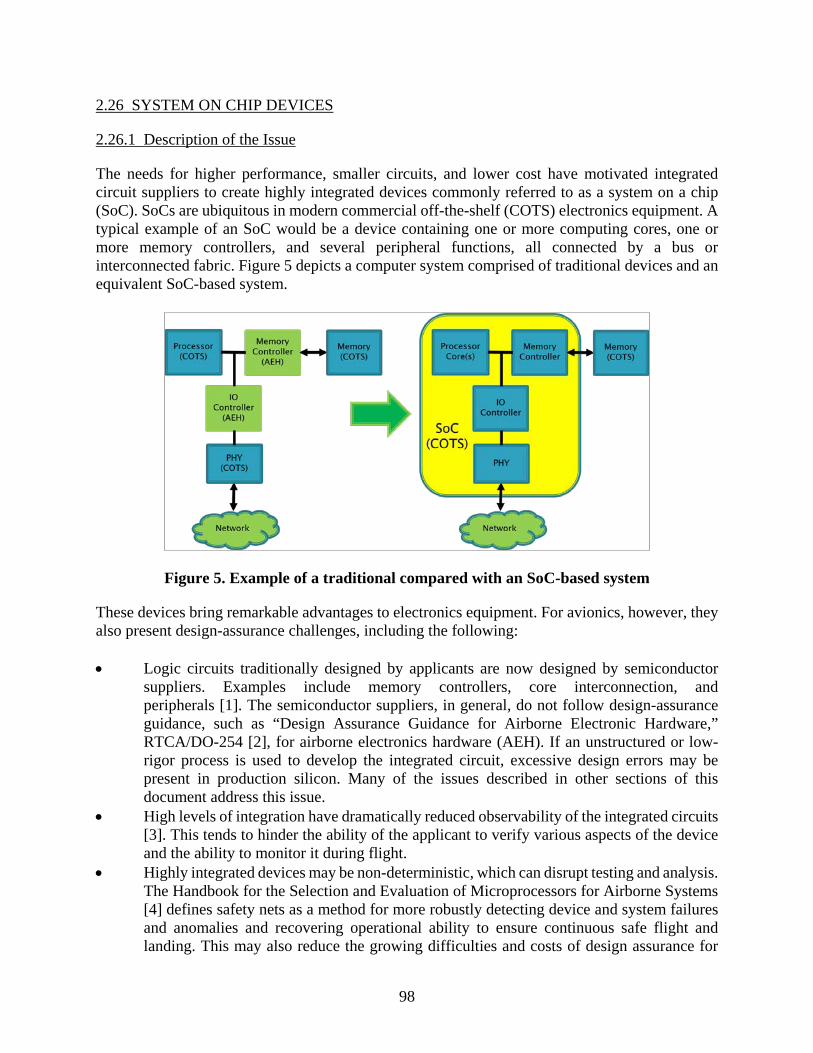
98
2.26 SYSTEM ON CHIP DEVICES
2.26.1 Description of the Issue
The needs for higher performance, smaller circuits, and lower cost have motivated integrated circuit suppliers to create highly integrated devices commonly referred to as a system on a chip (SoC). SoCs are ubiquitous in modern commercial off-the-shelf (COTS) electronics equipment. A typical example of an SoC would be a device containing one or more computing cores, one or more memory controllers, and several peripheral functions, all connected by a bus or interconnected fabric. Figure 5 depicts a computer system comprised of traditional devices and an equivalent SoC-based system.
Figure 5. Example of a traditional compared with an SoC-based system
These devices bring remarkable advantages to electronics equipment. For avionics, however, they also present design-assurance challenges, including the following: • Logic circuits traditionally designed by applicants are now designed by semiconductor
suppliers. Examples include memory controllers, core interconnection, and peripherals [1]. The semiconductor suppliers, in general, do not follow design-assurance guidance, such as “Design Assurance Guidance for Airborne Electronic Hardware,” RTCA/DO-254 [2], for airborne electronics hardware (AEH). If an unstructured or low-rigor process is used to develop the integrated circuit, excessive design errors may be present in production silicon. Many of the issues described in other sections of this document address this issue.
• High levels of integration have dramatically reduced observability of the integrated circuits [3]. This tends to hinder the ability of the applicant to verify various aspects of the device and the ability to monitor it during flight.
• Highly integrated devices may be non-deterministic, which can disrupt testing and analysis. The Handbook for the Selection and Evaluation of Microprocessors for Airborne Systems [4] defines safety nets as a method for more robustly detecting device and system failures and anomalies and recovering operational ability to ensure continuous safe flight and landing. This may also reduce the growing difficulties and costs of design assurance for

99
highly integrated, complex, non-deterministic AEH and software within aircraft systems and the labor burden for FAA regulation compliance and design assurance
Since an SoC may implement a substantial portion of a system, there exists a broader concern that architectural decisions are also made by the suppliers of COTS SoCs. This means that higher-level aspects of the system (e.g., integration of functionality; allocation of communication channels and bandwidth between portions; and power distribution nets) that use the COTS SoC are determined by the SoC supplier. For example, the determinism of a computing system could be highly influenced by the architectural choices made by the COTS SoC supplier. 2.26.2 Relationship to Safety and Certification
Insufficient development assurance for a COTS SoC could lead to design errors in fundamental devices of safety-critical systems. Problems such as reduced availability, loss of function, misleading information, common-mode faults, or inability to continue safe flight and landing could result. In addition, certification could be affected if a supplier’s development processes diminish the applicant’s ability to properly understand and use the device. This, in turn, reduces the ability to ensure that the equipment in which it is incorporated performs its intended function. A highly integrated, complex device that exhibits non-deterministic behavior can be extremely difficult to completely assure system design and be exhaustively tested and/or analyzed. The safety-net approach is an alternative way to mitigate the risks associated with COTS SoCs via both passive and active methods designed into aircraft systems. If it is not feasible to show that complex aircraft systems are sufficiently free of anomalous behavior by evaluating system devices, the safety-net alternative can mitigate unforeseen or undesirable COTS operation by detecting and recovering from anomalous behavior at the operational system level. This approach requires the safety net be designed as a function within the aircraft system. The safety net can include passive monitoring functions, active fault-avoidance functions, and control functions for recovery of system operations. System architecture and control and recovery functions should be designed to facilitate effective system recovery from anomalous events. Certification of systems using COTS SoCs is complicated by the potential lack of design artifacts for the SoC and the reduced ability to monitor and control SoC functions. 2.26.3 Existing Activity
The European Aviation Safety Agency (EASA) Certification Memorandum (CM)-SWCEH-001 [1], EASA research project EASA.2008/1 [5], and AFE 43-developed Handbook for the Selection and Evaluation of Microprocessors for Airborne Systems [3] all address this issue of insufficient development assurance for COTS SoCs in varying degrees. EASA CM-SWCEH-001 addresses many other aspects of COTS SoCs. Upcoming documents from EASA (Multicore Certification Review Item) and the FAA (Multicore Issue Paper and Policy Statements) are expected to address multicore devices in more detail.

100
2.26.4 Technology Weakness/Deficiency
Limited observability and controllability of SoC devices inhibit the ability to monitor and debug these devices. These limitations affect the ability to perform design assurance for systems containing non-deterministic devices and inhibit complexity management in systems that use SoC devices. 2.26.5 Process Weakness/Deficiency
As evidenced by their success in bringing reliable devices to market, most COTS SoC suppliers competently design and verify their products. However, these suppliers rarely follow the structured development processes described in DO-254 [2]. A process for aerospace companies to obtain COTS SoC supplier design and verification information for use as source information in certification activities is not well-accepted or established. 2.26.6 Recommendation/Desired Outcome
The AFE 75 PMC recommends that further basic level research involving semiconductor industry collaboration be performed on this issue. One desired outcome is the creation of an aerospace WG, which builds a framework for collaboration between COTS SoC suppliers and the aerospace industry. This group would: • Establish processes for COTS SoC suppliers to efficiently and securely disclose source
information to aerospace customers. • Establish recommended lists for “disclosed” and “assessed” data from integrated circuit
suppliers to the aerospace industry. Disclosed data would be securely disseminated to aerospace customers; assessed data would be assessed one time, and the assessment results would be made part of the disclosed data.
• Create guidance for the COTS SoC industry which describe development practices (e.g., structured processes, requirements-driven development) and design practices (e.g., undocumented feature interlocks) that would be of benefit to applicants.
• Share process and guidance information with the silicon industry. Safety nets could show that systems are sufficiently impervious to anomalous behavior by ensuring continuous functional availability and reliability, satisfying applicable regulations, and meeting airworthiness requirements. However, research and development should be performed to determine methods and standards to support modified design assurance and certification requirements for the safety net approach. 2.26.7 References
1. “Development Assurance of Airborne Electronic Hardware,” EASA CM-SWCEH-001, March 2012.
2. “Design Assurance Guidance for Airborne Electronic Hardware,” DO-254/ED-80, RTCA/EUROCAE, April 19, 2000.
3. Wang, T., Stroud, C., and Touba, N., “System-on-Chip Test Architectures: Nanometer Design for Testability (Systems on Silicon),” Morgan Kaufmann, 2007.

101
4. Aerospace Vehicle Systems Institute, AFE 43, “Handbook for the selection and evaluation of microprocessors for airborne systems,” FAA Report DOT/FAA/AR-11/2, February 2011.
5. European Aviation Safety Agency Research Project, EASA.2008/1, “Safety Implications of the use of System-on-Chip (SoC) on Commercial off-the-Shelf (COTS) Devices in Airborne Critical Applications,” 2008.
2.26.8 Acronyms
The following acronyms were used in section 2.26. AEH Airborne electronic hardware (DO-254 developed ASICs and FPGAs) AFE Authorization for expenditure AFE 43 Selection and Evaluation of Microprocessors for Critical Airborne Systems CEH Complex electronic hardware CM Certification memorandum COTS Commercial off-the-shelf DOT Department of Transportation EASA European Aviation Safety Agency ED EUROCAE document EUROCAE European Organisation for Civil Aviation Equipment RTCA RTCA, Inc. (formerly Radio Technical Commission for Aeronautics) SoC System on chip 3. AFE 75 RESULTS AND CONCLUSIONS
This AFE 75 report, based on global industry and regulatory expert experience, illustrates only the elemental aspects concerning COTS AEH issues (i.e., known issues) and provides information and methods for COTS AEH solution development, including: • Use of existing standards and guidance documents as a structure for future evolution of
COTS standards. • Future COTS standards to implement this structure. • Use of the Aerospace Vehicle Systems Institute as a mechanism for combined
industry/regulatory/manufacturing research and development of COTS issues related to the development of COTS standards and guidance.
• Mechanisms to shortcut the slow evolution of standards. • A candidate vision of the eventual COTS standards linked to evolving development of
assurance standards. • Identification of standard bodies responsible for the implementation of the ongoing COTS
solutions. All organizations and individuals who work with COTS AEH in avionics should read and understand this report. Further, those who address these COTS AEH issues should use AFE 75 research results to address current and future COTS AEH issues.

102
Although both the commercial and military segments of the aerospace market are increasingly dependent on COTS, there is no aerospace consensus on methods to ensure their safety and airworthiness in AEH, nor on criteria to verify that those methods are used properly in design, production, or support. A major characteristic of the COTS electronics market is the rapidity with which it changes and the regular emergence of new issues that can affect avionics safety and airworthiness. The COTS issues identified in this report are seen as a baseline set of issues. They may be modified, as needed, and additional issues added in the future. AFE 75 explains how the issues can impact safety and airworthiness of aircraft and how they can be addressed in the certification process. To the extent possible, existing industry handbooks, standards, reports, and technical publications were leveraged in the recommended document structure and will be in future work beyond the scope of AFE 75. Where additional knowledge is required, research to produce that knowledge and the candidate organizations responsible, are identified. This report provides a common structured approach for industry use to evaluate COTS AEH issues. It is applied to issues addressed in this report and is recommended for application to future issues not addressed herein. The approach is presented in a manner that supports the development of project-level COTS AEH mitigations that can be rolled into development design assurance and a practical compliance solution for FAA engineers and delegates and standards administrators. This report provides a stand-alone treatment of each issue (section 2), a five-step suggested evolution of COTS and development assurance standards and guidelines (appendix B), and a comparison of the 21 technological issues (appendix C). The structured approach provides: • Details regarding technical information about each issue. • Research required to provide new knowledge needed to implement solutions for the issues. • Required tools, standards, and guidance needed for COTS-based systems development
assurance, certification, and maintenance. • Recommended certification and assessment criteria and methods for the given issues. This structured approach can be used to evaluate and address emerging COTS AEH issues. System/aircraft development projects will be required to deal with COTS AEH issues. Some of these COTS issues will be beyond the resources of a single project or development organization. AFE 75 demonstrates that the Aerospace Vehicle Systems Institute (AVSI) is a viable research environment to enable multiple industry and regulatory partners to address COTS issues that are too large, too complex, and unresolved to be addressed by individual projects or single organizations. Aerospace management must become aware of the serious nature and scope of COTS AEH issues and support the communal research necessary to avoid project roadblocks, achieve required safety, and avoid potential liabilities associated with breaches of operational safety. The nature of the COTS AEH challenge is that the methods to certify safety and airworthiness are difficult, if not impossible, to define in an objective way. Furthermore, the methods that might be used are likely to be expensive and time-consuming. It is necessary, therefore, to achieve a consensus within the aerospace industry and regulatory agencies regarding the methods,

103
documents, and tools to be used in the development assurance and certification processes, along with the criteria and methods to verify compliance. The results of this report are designed to be actionable, including the detailed descriptions and recommendations for the issues, the roadmap for the development of COTS AEH standards and guidelines, and the structured approach for the evaluation of COTS AEH issues. The results offer a baseline for industry and regulatory action to achieve implemented solutions for current and future COTS AEH issues. This report provides complete results and conclusions for the selected COTS AEH issues. It provides the final recommended structure shown in appendix B (see figure B-5). Further, this report provides a brief description of project results and conclusions for each issue in table C-1 of appendix C, which enables rapid comparison of any subset of issues. Table C-1 also provides a structured approach for the evaluation of additional COTS AEH issues. In each section, this report is structured to provide consistently organized results and conclusions for each issue. Each section 2.n contains a separate reference list and acronym/abbreviation list for each issue. Further, this report includes a composite reference list, as shown in appendix A, and a composite acronym/abbreviation list. Therefore, because of this report’s structure, it may be understood fully from a total report standpoint and from an individual issue standpoint. Each section 2 issue is structured to include each of the following sections, where “n” represents one representative section number of the report (e.g., section 2.1.1 is the “Description of the issue” section for the COTS Assemblies’ issue): 2.n.1 Description of the issue 2.n.2 Relationship to safety and certification 2.n.3 Existing activity 2.n.4 Technology weakness/deficiency 2.n.5 Process weakness/deficiency 2.n.6 Recommendation/desired outcome 2.n.7 References 2.n.8 Acronyms and Abbreviations Appendix B addresses a five-step evolution of Candidate Comprehensive Guidance Documents to project implementation of standards and guidance documents required to address the COTS issues to the level of accomplished AFE 75 research. Appendix C, “COTS Issues, Problems, Solutions Overview,” provides a matrix of the following aspects of each of the selected technological issues, thus allowing detailed comparisons: • Identifies each issue (columns in the matrix and rows for each of the following aspects):
– References each issue in section 2.n. – Identifies current standards, if existing. – Does the standard adequately address the issue defined?

104
– Should the current standard be revised? – Should a new standard be created? – Identifies standard owners only for standards identified. – What additional work is needed for regulatory use? – What additional research is needed? – Will issue be addressed if the AFE 75 PMC publishes the report and does nothing
further? Appendix D: categorizes similarities in AEH COTS issues that may support planning for additional research.

A-1
APPENDIX A—COMPOSITE AFE 75 FINAL REPORT REFERENCES
The following references, in alphabetic order, list all references used in this document and identify the issue section (2.X) and reference number [#] in each section. Accellera Systems Initiative, independent, not-for profit organization dedicated to create, support, promote, and advance system-level design, modeling, and verification standards for use by the worldwide electronics industry, www.accellera.org (accessed on 12/11/2014). 2.15[3]. Aeronautical Recommended Practice, ARP4761, “Appendix for Incorporation of Atmospheric Neutron Single Event Effects Analysis into Safety Assessment,” AVSI Project 72 Task Group, November 29, 2011. 2.5[8]. AeroSpace and Defense Industries Association of Europe (ASD), http://www.asd-europe.org/ (accessed on 12/11/2014). 2.14[10]. Aerospace Vehicle Systems Institute AFE 72, “Incorporation of Atmospheric Neutron Single Event Effects Analysis into Safety Assessment,” Draft Aerospace Information Report 219, May 16, 2012. 2.5[9]. Aerospace Vehicle Systems Institute, AFE 43, “Handbook for the selection and evaluation of microprocessors for airborne systems,” FAA Report DOT/FAA/AR-11/2, February 2011. 2.13[3], 2.21[2], 2.26[4]. Aerospace Vehicle Systems Institute, AFE 43 Phase 1 Report, “Microprocessor Evaluations for Safety-Critical, Real-Time Applications,” FAA Report DOT/FAA/AR-06/34, December 2006. 2.21[4]. Aerospace Vehicle Systems Institute, AFE 43 Phase 2 Report, “Microprocessor Evaluations for Safety-Critical, Real-Time Applications,” FAA Report DOT/FAA/AR-08/14, June 2008. 2.21[5]. Aerospace Vehicle Systems Institute, AFE 43 Phase 3 Report, “Microprocessor Evaluations for Safety-Critical, Real-Time Applications,” FAA Report DOT/FAA/AR-08/55, February 2009. 2.21[6]. Aerospace Vehicle Systems Institute, AFE 43 Phase 4 Report, “Microprocessor Evaluations for Safety-Critical, Real-Time Applications,” FAA Report DOT/FAA/AR-10/21, September 2010. 2.21[7] Aerospace Vehicle Systems Institute, AFE 43 Phase 5 Report, “Microprocessor Evaluations for Safety-Critical, Real-Time Applications,” FAA Report DOT/FAA/AR-11/5, May 2011. 2.21[8]. Aerospace Vehicle Systems Institute, AFE 72, “Mitigating Radiation Effects,” Technical Reports, various dates. 2.5[1]. Aerospace Vehicles System Institute, Commercial off-the-Shelf Issues and Challenges for Airborne Electronics Hardware, AVSI Project 75 Task 1 Report, May 7, 2012. 2.5[16].

A-2
American National Standards Institute, Electronic Industries Alliance, ANSI/EIA-933, “Standard for Preparing a COTS Assembly Management Plan,” August 2001. 2.1[1]. ANADEF (ANAlyse de DEFaillance French Association working on electronic component failure analysis), http://www.anadef.org/lanadef.html (last accessed 10/27/2013). 2.14[5]. Baker, R.J., “DRAM Circuit Design, Layout, and Simulation,” 3rd Edition (IEEE Press Series on Microelectronic Systems), Wiley-IEEE, 2010. 2.4[2]. Biddle, S.R., “Reliability implications of derating high-complexity microcircuits,” COTS Journal, Vol. 2, No. 2, February 2001. 2.2[5], 2.20[3]. Center for Advanced Life Cycle Engineering, CALCE (Maryland University), http://www.calce.umd.edu/general/center/consortium.htm (last accessed 12/11/2014). 2.14[4]. Colwell, R.P., “Pentium Chronicles: The People, Passion, and Politics Behind Intel’s Landmark Chips,” pp. 87-89, Wiley-IEEE, 2005. 2.11[4]. Condra, L., Hillman, C., Redman, D., and Wyrwas, E., “Microcircuit Reliability Prediction Based on Physics of Failure Models,” IMAPS Advanced Technology Workshop on High Reliability for Military Applications, August 31, 2010. 2.6[1]. Design & Reuse (D&R) [7], http://www.design-reuse.com (last accessed 12/11/2014). Web portal for disseminating value-added information on electronic virtual components, specifically intellectual property (IP), systems-on-chips (SoCs), and provides enterprise-level IP management platforms. At present, D&R manages 12,000 IP cores from 400 vendors. 2.15[7]. “Diminishing Manufacturing Sources and Material Shortages,” Defense Standardization Program Office, August 2012. 2.22[2]. Directive 2002/95/EC of the European Parliament and of the Council, “The Restriction of the use of certain Hazardous Substances in electrical and electronic equipment,” January 27, 2003. 2.8[1]. ECSS-Q-ST-30-11C Rev 1, “Space product assurance, Derating - EEE components,” October 4, 2011 , http://www.ecss.nl/forums/ecss/_templates/default.htm?target=http://www.ecss.nl/forums/ecss/dispatch.cgi/standards/docProfile/100807/d20111006072316/No/t100807.htm (last accessed 12/11/2014). 2.20[6]. Electronic Device Failure Analysis Society, EDFAS, http://edfas.asminternational.org/portal/site/edfas/MyEDFAS/Home/ (last accessed 12/11/2014). 2.14[6]. European Aviation Safety Agency (EASA), Certification Memorandum, CM – SWCEH – 001, Development assurance of airborne electronic hardware, Issue 01, Revision 01, March 2012. 2.13[2], 2.15[11], 2.21[1], 2.26[1].
A-3
European Aviation Safety Agency Certification Memorandum, CM-SWCEH-001, “Development Assurance of Airborne Electronic Hardware,” August 2011. 2.9[1], 2.11[1]. European Aviation Safety Agency Research Project, EASA.2008/1, “Safety Implications of the use of System-on-Chip (SoC) on Commercial off-the-Shelf (COTS) Devices in Airborne Critical Applications,” 2008. 2.26[5]. European Aviation Safety Agency Safety Information Bulletin, SIB 2011-27, “Suspect (Bogus - Counterfeit) Integrated Circuits,” November 18, 2011. 2.10[4]. European Electronic Component Manufacturers Industry Association, EPCIA, http://acronyms.thefreedictionary.com/European+Electronic+Component+Manufacturers+Association (last accessed 11/03/2014). 2.14[1]. Federal Aviation Administration (FAA), Advisory Circular AC 20-157, “How to Prepare Reliability Assessment Plans for Aircraft Systems and Equipment,” January 19, 2007. 2.7[5]. Federal Aviation Administration (FAA), FAA Order 8110.105 Chg 1, SIMPLE AND COMPLEX ELECTRONIC HARDWARE APPROVAL GUIDANCE, September 23, 2008. 2.15[8]. FIDES: A Methodology for Components Reliability, http://fides-reliability.org/ (last accessed 12/11/2014). 2.14[3]. Forsberg, H., Månefjord, T., “Derating Concerns for Microprocessors Used in Safety-Critical Applications,” IEEE Aerospace and Electronic Systems Magazine, March 2009. 2.2[3]. Forsberg, H., (Saab), “Comparison Between The Handbook for the Selection and Evaluation of Microprocessors for Airborne Systems and EASA’s Certification Memorandum SWCEH – 001,” October 2012. 2.13-4, 2.21[3]. General Aviation Manufacturer Association (GAMA), http://www.ask.com/wiki/General_Aviation_Manufacturers_Association (last accessed 12/11/2014). 2.14[9]. Henderson, D. et al., “Power7 System RAS: Key aspects of Power Systems Reliability, Availability, and Serviceability,” IBM Systems and Technology Group, October 3, 2012. 2.3[6]. Hsiao, M.Y., “A Class of Optimal Minimum Odd-weight SEC-DED Codes,” IBM Journal of Research and Development, 1970. 2.4[6]. Institute for Interconnecting and Packaging Electronic Circuits (IPC), https://acc.dau.mil/CommunityBrowser.aspx?id=22385&lang=en-US (last accessed 12/11/2014). 2.19[2].

A-4
Institute for Interconnecting and Packaging Electronic Circuits, IPC-D-279, “Design Guidelines for Reliable Surface Mount Technology Printed Wiring Board Assemblies,” July 1996. 2.19[3]. Institute for Interconnecting and Packaging Electronic Circuits, IPC-SM-785, “Guidelines for Accelerated Reliability Testing of Surface Mount Solder Attachments,” November 1992. 2.19[4]. Institute of Electrical and Electronics Engineers Standard 1149.1, “Standard Test Access Port and Boundary Scan Architecture,” IEEE, July 2001. 2.11[5]. International Electrotechnical Commission (IEC) Technical Committee (TC), TC 107, “Process Management for Avionics,” http://www.iec.ch/dyn/www/f?p=103:7:0::::FSP_ORG_ID:1304 (last accessed 12/11/2014). 1[3], 2.5[12], 2.6[6], 2.8[12]. International Electrotechnical Commission/Publically Available Specification, IEC/PAS 62668-1, “Process management for avionics – Counterfeit prevention – Part 1: Avoiding the use of counterfeit, fraudulent and recycled electronic components,” Edition 1.0, May 2012. 2.10[5]. International Electrotechnical Commission/Publically Available Specification, IEC/PAS 62647-21 “Process management for avionics - Aerospace and defense electronic systems containing lead-free solder - Part 21: Program management - Systems engineering guidelines for managing the transition to lead-free electronics,” Edition 1.0, July 2011. 2.8[7]. International Electrotechnical Commission/Publically Available Specification, IEC/PAS 62647-22, edition 1.0, “TC/SC 107, Process management for avionics - Aerospace and defense electronic systems containing lead-free solder - Part 22: Technical guidelines,” July 2011. 2.8[8]. International Electrotechnical Commission/Publically Available Specification, IEC/PAS 62647-23, edition 1.0, “Process management for avionics - Aerospace and defense electronic systems containing lead-free solder - Part 23: Rework and repair guidance to address the implications of lead-free electronics and mixed assemblies,” July 2011. 2.8[9]. International Electrotechnical Commission/Publically Available Specification, IEC/PAS 62647-3, edition 1.0, “Process management for avionics - Aerospace and defense electronic systems containing lead-free solder - Part 3: Performance testing for systems containing lead-free solder and finishes,” July 2011. 2.8[6]. International Electrotechnical Commission/Technical Report, IEC/TR 62240, “Process management for avionics - Use of semiconductor devices outside manufacturers’ specified temperature range,” Edition 1.0, 2005. 2.20[2]. International Electrotechnical Commission/Technical Specification, IEC/TS 62239-1, “Process management for avionics - Management plan - Part 1: Preparation and maintenance of an electronic components management plan,” International Electrotechnical Commission, ed.,
A-5
Edition 1.0, July 2012. 2.1[4], 2.2[2], 2.5[15], 2.6[8], 2.9[3], 2.13[5], 2.14[8], 2.16[2], 2.20[1], 2.21[9], 2.22[3]. International Electrotechnical Commission/Technical Specification, IEC/TS 62396-1, “Process Management for Avionics – Atmospheric Radiation Effects – Part 1: Accommodation of Atmospheric Radiation Effects within Avionics Electronic Equipment,” Edition 1.0, March 2006. 2.2[7], 2.5[3]. International Electrotechnical Commission/Technical Specification, IEC/TS 62396-2, “Process Management for Avionics – Atmospheric Radiation Effects – Part 2: Guidelines for Single Event Effects Testing for Avionics Systems,” Edition 1.0, August 2008. 2.5[4]. International Electrotechnical Commission/Technical Specification, IEC/TS 62396-3, “Process Management for Avionics – Atmospheric Radiation Effects – Part 3: Optimising System Design to Accommodate the Single Event Effects (SEE) of Atmospheric Radiation,” Edition 1.0, August 2008. 2.5[5]. International Electrotechnical Commission/Technical Specification, IEC/TS 62396-4, “Process Management for Avionics – Atmospheric Radiation Effects – Part 4: Guidelines for Designing with High Voltage Aircraft Electronics and Potential Single Event Effects,” Edition 1.0, July 2008. 2.5[6]. International Electrotechnical Commission/Technical Specification, IEC/TS 62396-5, “Process Management for Avionics – Atmospheric Radiation Effects – Part 5: Guidelines for Assessing Thermal Neutron Fluxes and Effects in Avionics Systems,” Edition 1.0, March 2008. 2.5[7]. International Electrotechnical Commission/Technical Specification, IEC/TS 62564, “Process management for avionics – Aerospace qualified electronic components (AQEC) - Part 1: Integrated circuits and discrete semiconductors,” Edition 2.0, August 2011. 2.6[5]. International Electrotechnical Commission/Technical Specification, IEC/TS 62647-1, “Process management for avionics - Aerospace and defense electronic systems containing lead-free solder - Part 1: Preparation for a lead-free control plan,” Edition 1.0, August 2012. 2.8[4] Alt. International Electrotechnical Commission/Technical Specification, IEC/TS 62647-2, “Process management for avionics - Aerospace and defense electronic systems containing lead-free solder - Part 2: Mitigation of deleterious effects of tin,” Edition 1.0, November 2012. 2.8[5] Alt. International Symposium for Testing and Failure Analysis, ISTFA, http://www.asminternational.org/content/Events/istfa/ (last accessed 12/11/2014). 2.14[7]. International Technology Roadmap for Semiconductors, Lithography, 2011, http://www.itrs.net/links/2011ITRS/Home2011.htm (last accessed 12/11/2014). 2.4[5].

A-6
Jayanth, S. et al., “Exploiting structural duplication for lifetime reliability enhancement,” ISCA ’05 Proceedings, 32nd International Symposium on Computer Architecture, June 4–8. 2005, pp. 520–531. 2.3[4]. Jayanth, S. et al., “Lifetime Reliability: Toward an Architectural Solution,” IEEE Micro, May–June 2005. 2.3[7]. Joint Electronic Device(s) Engineering Council Document, JESD 47, Revision 1 Released for Stress-Test-Driven Qualification of Integrated Circuits, July 2012. 2.6[9]. Joint Electronic Device(s) Engineering Council Publication JEPP122G, “Failure Mechanisms and Models for Semiconductor Devices,” October 2011. 2.4[9], 2.6[10]. Joint Electronic Device(s) Engineering Council, JESD89, “Measurement and Reporting of Alpha Particles and Terrestrial Cosmic Ray Induced Soft Errors in Semiconductor Devices,” October 2006. 2.5[10]. Joint Electronic Device(s) Engineering Council, Solid State Technology Association, JEP149, “Application thermal derating methodologies,” November 2004. 2.2[11]. Joint Electronic Device(s) Engineering Council, Solid State Technology Association, JESD46D, “Customer Notification of Product/Process Changes by Solid-State Suppliers,” December 1, 2011. 2.16[1]. Joint Electronic Device(s) Engineering Council, www.jedec.org (last accessed 12/11/2014). 2.5[14]. Keeth, B., Baker, R.J., Johnson, B., and Lin, F., “DRAM Circuit Design: Fundamental and High-Speed Topics,” (IEEE Press Series on Microelectronic Systems), Wiley-IEEE, 2007. 2.4[1]. Lead-free Electronics in Aerospace Project Working Group (LEAP WG) formed in 2004, http://www.aciusa.org/leadfree/LFS_SUMMIT-PDF/12_TOUW_AIA-AMC-GEIA_LEAP_WG_Brief.pdf (last accessed 11/02/2013). 2.8[2] “Lead-free Electronics Manhattan Project Reports,” Phase 1, U.S. Government Contract No. N00014-08-D-0758, Benchmark Center of Excellence, ACI Technologies, 2009. 2.8[10]. “Lead-free Electronics Manhattan Project Reports,” Phase 2, U.S. Government Contract No. N00014-08-D-0758, Benchmark Center of Excellence, ACI Technologies, 2010. 2.8[11]. Linklater, M., “Optimizing Cell Code,” Game Developer Magazine, April 2007: pp. 15–18. 2.3[2]. Mesgarzadeh, B., Soderquist, I., and Alvandpour, A., “Reliability Challenges in Avionics due to Silicon Aging,” 15th IEEE International Symposium on Design and Diagnostics of Electronic Circuits and Systems, DDECS,” Tallinn, Estonia, April 18–20, 2012, pp. 342–347. 2.6[3].

A-7
Micheloni, R., Crippa, L., Marelli, A., “Inside NAND Flash Memories,” Springer, 2010. 2.4[3]. Military Handbook, MIL-HDBK 217F, “Reliability Prediction of Electronic Equipment,” notice 2, February 28, 1995. 2.7[1], 2.14[2], 2.19[5]. Military Handbook, MIL-HDBK 338B, “Electronic reliability design handbook,” October 1998. 2.2[10]. Military Handbook, MIL-HDBK 454B, “General guidelines for electronic equipment,” April 15, 2007. 2.2[9]. Military Standard, MIL-STD 1547B, “Electronic parts, materials, and processes for space and launch vehicles,” December 1, 1992. 2.2[8]. Moliere et al., “A New Policy for COTS Selection: Overcome the DSM Reliability Challenge,” SAE International Journal of Aerospace, vol. 4, no. 2, pp. 1475–1484, November 2011. 2.4[8]. Morgan, T.P., “Hot Intel teraflops MIC coprocessor action in a hotel,” The Register, November 16, 2011. 2.3[3]. MultiCore for Avionics (MCFA) group, http://onboard.thalesgroup.com/2013/successful-multi-core-for-avionics-working-group-meeting-with-authorities/ (last accessed 12/11/2014). 2.11[6]. National Aeronautics and Space Administration/Technical Publication, NASA/TP—2003–212242, “Instructions for EEE Parts Selection, Screening, Qualification, and Derating,” May 2003; EEE-INST-002: Last update: April 2008, Incorporated Addendum 1. 2.20[4]. “National Defense Authorization Act for Fiscal Year 2013,” 112th Congress, 2nd Session, H.R. 4310. 2.10[3]. Oak Ridge National Laboratory (ORNL), http://www.ornl.gov/ (last accessed 12/11/2014). 2.5[13]. Open SystemC Initiative (OSCI), integrated in Accellera [3] in December 2011. The Open SystemC Initiative (OSCI) used to be a collaborative effort to support and advance SystemC as a de facto standard for system-level design. SystemC is an interoperable, C++ SoC/IP modeling platform for fast system-level design and verification. 2.15[6]. Open Verilog International, integrated in Accellera [3] in 2000. 2.15[4]. Pan, A. et al, “Improving Yield and Reliability of Chip Multiprocessors,” ’09 Proceedings of the Conference on Design, Automation and Test in Europe,” Nice, France, April 20–24, 2009, pp. 490–495. 2.3[5]. Pb-free Electronics Risk Management (PERM) Consortium, http://www.ipcoutlook.org/mart/51458F.shtml (last accessed 12/11/2014). 2.8[3].

A-8
Perry, W., “Specifications & Standards - A New Way of Doing Business,” June 29, 1994, http://www.sae.org/standardsdev/military/milperry.htm (last accessed 12/11/2014). 2.7[2]. Ramadan, N.H., “Redundancy Yield Model for SRAMS,” Intel Technology Journal Q4 ’97. 2.3[1]. Reick, K. et al., “Fault-Tolerant Design of the IBM Power6 Microprocessor,” IEEE Micro, March–April 2008. 2.3[8]. “Reliability Roadmap and Proposed Projects,” AFE74S1 Final Report, Aerospace Vehicle Systems Institute, May 22, 2012 (not currently available to the public). 2.7[4]. Report of the Challenge 2000 Subcommittee of the FAA Research, Engineering, and Development Advisory Committee to the Administrator of the FAA,” March 6, 1996. 2.22[1]. RNC-CNES-Q-60-522, “Transformation of the environmental constraints into components requirements,” Issue 1, April 14, 2003. 2.20[5]. RTCA, DO-160, “Environmental Conditions and Test Procedures for Airborne Equipment,” December 8, 2010. 2.19[1]. RTCA, DO-178B, “Software Considerations in Airborne Systems and Equipment Certification, December 1, 1992,”; DO-178C, January 5, 2012. 2.17[1]. RTCA, DO-248C “Supporting Information for DO-178C and DO-278A, RTCA DO-248C,” December 13, 2011. 2.5[11]. RTCA, DO-254 (EUROCAE ED-80), “Design assurance guidance for airborne electronic hardware,” April 19, 2000. 2.13[1], 2.15[1], 2.17[2], 2.26[2]. Schroeder, B., Pinheiro, E., Weber, W.D., “DRAM Errors in the Wild: A Large-Scale Field Study,” SIGMETRICS/Performance ’09, June 15–19, 2009, http://dl.acm.org/citation.cfm?doid=1555349.1555372, (last accessed 12/11/2014). 2.4[10]. Siewiorek, D.P. and Swarz, R.S., “Reliable Computer Systems Design and Evaluation,” 3rd Edition, AK Peters, 1998. 2.4[7], 2.19[6]. SoCCER, SoC from Civilian to Armament Re-use. Project born from the idea of European leading industries in defense and aerospace and excellence academia and design houses with common interest for using Intellectual Property in Systems-on-Chip. Completed by 2005. 2.15[9]. SAE, International, SAE AS5553A, “Counterfeit Electronic Parts; Avoidance, Detection, Mitigation, and Disposition,” January 2013. 2.10[8]. SAE, International, SAE AS6174, “Counterfeit Materiel; Assuring Acquisition of Authentic and Conforming Material,” May 2012. 2.10[7].

A-9
SAE, International, SAE AS6462, AS5553, “Counterfeit Electronic Parts; Avoidance, Mitigation, and Disposition Verification Criteria,” November 2012. 2.10[9]. SAE International “Avionics Process Management Committee” (APMC), http://www.sae.org/works/committeeHome.do?comtID=TEASSTCAPMC (last accessed 12/11/2014). 2.1[2], 2.6[7], 2.7[6], 2.8[13]. SAE International, SAE ARP 5890A, “Guidelines for Preparing Reliability Assessment Plans for Electronic Engine Controls,” February 1, 2011. 2.7[3]. SAE International, SAE S18/Eurocae WG 63 “Complex Aircraft Systems,” http://www.eurocae.net/working-groups/wg-list/35-wg-63.html (last accessed 11/05/2013). 2.5[2]. SPIRIT Consortium, Structure for Packaging, Integrating and Re-using IP within Tool-flows, integrated in Accellera [3] in June 2009. 2.15[2]. Tarr, M., “Derating,” Online postgraduate courses for the electronics industry - Topics Library, Reliability issues and failure mechanisms, The University of Bolton, available at http://www.ami.ac.uk/courses/topics/0190_drat/index.html (last accessed 12/11/2014). 2.2[1]. TechAmerica Handbook, GEIA-HB-0005-1, “Program Management/Systems Engineering Guidelines For Managing The Transition To Lead-Free Electronics,” June 20, 2006. 2.8[7]. TechAmerica Handbook, GEIA-HB-0005-2, “Technical Guidelines for Aerospace and High Performance Electronic Systems Containing Lead-Free Solder and Finishes,” November 2007. 2.8[8]. TechAmerica Handbook, GEIA-HB-0005-3, “Rework/Repair Handbook to Address the Implications of Lead-Free Electronics and Mixed Assemblies in Aerospace and High Performance Electronic Systems,” September 1, 2008. 2.8[9]. TechAmerica Standard, ANSI/EIA-STD-4899A-2009, “Standard for preparing an electronic components management plan,” February 11, 2009. 2.2[6], 2.9[2]. TechAmerica Standard, GEIA-STD-0002-1, “Aerospace Qualified Electronic Component (AQEC) Requirements, Volume 1 – Integrated Circuits and Semiconductors,” August 1, 2005. 2.6[4]. TechAmerica Standard, GEIA-STD-0005-1-A, “Performance Standard for Aerospace and High Performance Electronic Systems Containing Lead-free Solder,” March 1, 2012. 2.8[4]. TechAmerica Standard, GEIA-STD-0005-2-A, “Standard for Mitigating the Effects of Tin Whiskers in Aerospace In High Performance Electronic Systems,” May 1, 2012. 2.8[5].

A-10
TechAmerica Standard, GEIA-STD-0005-3-A, “Performance Testing for Aerospace and High Performance Electronic Interconnects Containing PB-free Solder and Finishes,” March 1, 2012. 2.8[6]. TechAmerica Standard, GEIA-STD-0016, “Standard for Preparing a DMSMS Management Plan,” August 2011. 2.22[4]. TechAmerica Technical Bulletin, TB-0003, “Counterfeit Parts & Materials Risk Mitigation,” February 2009. 2.10[6]. United States Department of Commerce, Bureau of Industry and Security, Office of Technology Evaluation, “Defense Industrial Base Assessment: Counterfeit Electronics,” November 2009. 2.10[2]. United States Government Accountability Office Report to the Committee on Armed Services, U.S. Senate, “DoD Supply Chain – Suspect Counterfeit Electronic Parts Can Be Found on Internet Purchasing Platforms,” GAO-12-375, February 2012. 2.10[1]. UTE-80811-Edition A: Fides Methodology Guide, January 2011. 2.14[11]. VHDL International, integrated in Accellera in 2000. 2.15[5]. Wang, L., Stroud, C.E., and Touba, N.A., “System-on-Chip Test Architectures: Nanometer Design for Testability (Systems on Silicon),” Morgan Kaufmann, 2007. 2.11[2], 2.26[3]. Weste, N. and Harris, D., “CMOS VLSI Design: A Circuits and Systems Perspective,” 4th Edition, Addison Wesley, 2011 (chapter 15). 2.11[3]. White, M., “Scaled CMOS reliability and considerations for spacecraft systems: Bottom-up and Top-down Perspectives,” Reliability Physics Symposium (IRPS), 2012 IEEE International, Anaheim, California, April 15–19, 2012. 2.2[4]. Wyrwas, E.J. and Bernstein, J.B., “Quantitatively Analyzing the Performance of Integrated Circuits and Their Reliability,” IEEE Instrumentation & Measurement Magazine, February 2011, pp. 24–31. 2.6[2].

B-1
APPENDIX B—CANDIDATE COMPREHENSIVE GUIDANCE DOCUMENT STRUCTURE
As this study was started, it was recognized that it would be important to envision how the standards and guidance that were to be identified or created would be delivered to the avionics industry. The need to get the standards integrated into the development process became obvious as issues were identified and the risks that they represented were outlined. Within the study group, the urgency of deployment reiterated the need for an early deployment of the standards that already exist to assist with providing consistent guidance to the industry and regulatory bodies. Some of the more obvious methods available for this delivery, such as RTCA DO-254/EUROCAE ED80, have historically taken long periods of time to get published. Therefore, alternative methods were explored and this appendix presents the methods agreed on to do this in the study. The remaining alternatives that were discussed were deliberately not captured in an effort to reduce potential confusion and conflicts that could occur from presenting multiple options. The recommended method includes a stepped approach to aid in the early deployment of existing bodies of work and to accommodate the further development of standards to address these and other issues. The figures illustrate a possible or recommended structure approach and are presented in the following phases: Current structure of development assurance standards: Step 1. Addition of COTS standards to the development assurance standards via ECMP Step 2. Alternative uses of ECMP standards Step 3. Addition of new COTS standards to the development assurance standards Step 4. Possible final step that could integrate all of the additional standards into the
development assurance standards Figures B-1–B-6 illustrate a recommended, structured approach and are presented in the following phases: Figure B-1. This figure, “Current Structure of Primary Development Assurance Standards,” shows three primary development assurance standards in use today. DO-160 is the most widely used environmental test standard. The other two documents shown are supporting documents. As noted, we are assuming that ARP4761 will be updated to 4761A. It should be noted that DO-160, which is of significant use in the development of systems and hardware, is not connected to the other development assurance standards. Figure B-2. Step 1—This figure shows the addition of COTS standards to the Primary Development Assurance Standards via an update of the current ECMP standards by using the recommendations provided for those respective standards by this AFE 75 Project. These are some of the key standards identified by AFE 75, as currently available and applicable to the issues raised in this study. It suggests that these standards are applicable via the inclusion of ECMP standards. Also note that we are illustrating the need to connect DO-160 and the ECMP to ARP4754A. This interaction may not be practical at this time through the industry standard committees; however, the airworthiness authorities are considering a possible means of creating a regulatory link between the DO-160, ECMP, and ARP4754A.
B-2
Figure B-3. Step 2—This figure, “Alternative Use of Two ECMP Standards,” shows a minor change to the industry organization of the ECMP standards and illustrates two very similar yet different standards for ECMP: 1) SAE EIA STD 4899B and 2) IEC/TS 62239-1. The standards owners have indicated that the standards are in review and revision processes. It appears at this time that the international standard IEC/TS 62239 will be taking on a broader role and covering more topics than the SAE EIA STD 4899. We have therefore included this relationship for completeness. Figure B-4. Step 3—This figure shows the addition of new COTS Standards to the Primary Development Assurance Standards and projects the future evolution of standards necessary to address other issues associated with COTS that were identified by AFE 75. It suggests that IEC/TS 62239-1 is the best vehicle for ECMP standards. The effective and consistent use of these standards for addressing COTS issues depends on the certification authorities recognizing these ECMP standards. Figure B-5. Step 4—This figure shows a possible final step that could integrate all of the additional standards into the Primary Development Assurance Standards, which suggests a possible future path to full implementation of the COTS standards. If and when DO-254/ED-80 is updated to revision A, a supplement dedicated to COTS could be created that could encompass COTS issues as a part of the relevant ECMP or directly within the supplement. Some current industry leaders believe that this should be accomplished now, whereas others are not yet ready to initiate an RTCA, Inc. Special Committee to modify DO-254. Based on recent history regarding initiating committees for updating the current development assurance standards and having the revisions published, the AFE 75 PMC believes that the identified COTS issues contained in this report need to be recognized in a more urgent path than the natural time frame currently being followed for these updates. In the absence of this more urgent path being followed, figure B-5 may provide the best available recommendation for a standards structure in COTS assurance management. Figure B-6 shows the ECMP standard related to issue subject standards.

B-3
Figure B-1. Current structure of primary development assurance standards

B-4
Figure B-2. Step 1—ECMP standards are updated with AFE 75 findings

B-5
Figure B-3. Step 2—alternative use of two ECMP standards

B-6
Figure B-4. Step 3—adding standards based on additional AFE 75 findings

B-7
Figure B-5. Step 4—once DO-254 is open for revision, implement COTS assurance via DO-254 supplement

B-8
Figure B-6. ECMP standard related to issue subject standards

C-1
APPENDIX C—COTS ISSUES, PROBLEMS, SOLUTIONS OVERVIEW
The research for this AFE 75 Project was conducted to identify and define common issues, problems, and emerging solutions with the use of COTS AEH assurance that will likely affect the industry and regulatory authorities. The overview table (table C-1) summarizes in a sense the discussions, conclusions, references, and means by which the regulatory authorities can utilize these research results and assist the reader to obtain a quick grasp of these results. Section 2 was constructed to enable each individual issue section to be used as a standalone report. The overview table provides the report section identification for each issue along with the issue title. The overview chart covers the following selected technological issues identified in the report. The multiple and global electronic supply chain issues (section 2.12) were found to have no technological basis and have been omitted from the overview chart. • COTS assemblies • Derating • Sparing reliability • Commodity memory • Increased susceptibility to atmospheric radiation • Limited life semiconductors • Outdated reliability assessment methods • Transition to lead-free electronics • Availability and updates of errata • Counterfeit electronic parts • Undocumented features • Usage domain analysis • Production follow-up • Intellectual property • Unknown changes • Embedded controllers • Component packaging and monitoring reliability • Device uprating • Additional handbook considerations • Obsolescence management • System-on- chip devices Eight questions were considered to aid the research in determining if the issue was of real concern and whether there were possible emerging solutions to address the issues. The questions were: • Do any current standards exist? • Does the current standard adequately address the issue defined? • Does the current standard need to be revised? • Does a new standard need to be created? • Who are the standard(s) owner(s) for those standards identified with each issue?
C-2
• What additional work is needed for regulatory use? • Is additional research needed? • Will the issue be addressed if the AFE 75 PMC publishes this report and does nothing
further?

C-3
Table C-1. COTS issues, problems, and solutions overview
Issues
Report Section
References Do any current standards exist?
Does the current standard
adequately address the issue
defined?
Does the current standard need to
be revised?
Does a new standard need to be
created?
Who are the standard(s)
owner(s) for those standards identified with
each issue.
What additional work is needed for regulatory
use? Is additional
research needed?
If the AFE 75 PMC publishes this report and
does nothing further, will the issue be
addressed?
COTS Assemblies 2.1 EIA 933A No
ANSI EIA 933A is being revised to B
ANSI EIA 933B will be very similar to IEC/TS62239-2, Ed.1
SAE & IEC
Authorities need to recognize the Standard. Via this report, Industry is recommending that the standard is appropriate for Certification assurance.See Para 2.1.6
No Yes
Derating 2.2
Directly usable IEC/TS62239-1 Or EIA-STD-4899 A-2009
No Future No SAE & IEC
Derating is not currently required for certification. Via this report Industry is recommending that the standard is appropriate for Certification assurance.See Para 2.2.6
No Yes
Sparing Reliability 2.3 None N/A N/A Yes
Unknown Further research will likely create a clearer possible standard owner.
Not ready for authority action yet. Needs research to reference.
Yes, University level research that includes semiconductor industry collaboration . This could be led by AVSI. See Para 2.3.6
No. Sparings issue is relatively new for the avionics industry. The issue may escalate in the future when smaller process geometry components are used. The scope of the problem is still unknown; no Guidance exists and no other standards address this or similar topics. Therefore, this issue is at risk of not being addressed in the future.
Commodity Memory 2.4 None N/A N/A Yes
Unknown Further research will likely create a clearer possible standard owner.
Not ready for authority action yet. Needs research or a standard to reference.
Yes, Type of research needs to be clarified and determination of a working group that can address this.
No. Resolution of this issue requires collaboration between the semiconductor and aerospace industries. The structure of that collaboration needs to be defined for this issue and other similar issues described in this report.

C-4
Table C-1. COTS issues, problems, and solutions overview (continued)
Issues
Report Section
References Do any current standards exist?
Does the current standard
adequately address the issue
defined?
Does the current standard need to
be revised?
Does a new standard need to be
created?
Who are the standard(s)
owner(s) for those standards identified
with each issue.
What additional work is needed for
regulatory use? Is additional
research needed?
If the AFE 75 PMC publishes this report and
does nothing further, will the issue be
addressed?
Increased Susceptibility to Atmospheric Radiation
2.5 Directly usable IEC/TS62396 Series
Yes N/A
AFE 72 has SAE AIR6219 and an Appx to SAE ARP4761A under development.
SAE & IEC FAA & EASA are preparing regulatory material.
Ongoing via AFE 72. Yes
Limited Life Semiconductors 2.6 JESD47
IEC/TS62239-1 No Yes to IEC/TS62239-1
Under Development AFE 83
SAE & IEC
Not ready for authority action yet. Needs research or a standard to reference.
Ongoing via AFE 83. Yes
Outdated Reliability Assessment Methods
2.7
Loosely MIL-HB-217 SAE ARP5890 FIDES
Yes. These standards are not fully adequate, but they are a basis for what is commonly done. The work underway by the US DoD and AFE 80 and AFE 83 are the basis for the future.
Revision of MIL-HDBK-217 F is being considered
Under Development in AFE 80 & AFE 83
SAE
AC20-157 is a starting point. This report recommends that this AC be more fully utilized until further research is completed.See Para 2.7.6.
Ongoing AFE 80/83.
Yes; however, it is best led by AFE 80 and AFE 83 rather than by AF E75.
Transition to Lead-free Electronics
2.8 Directly usable IEC/TS 62647 Series
Yes
Some of the current standards are being revised at this time
No SAE & IEC
FAA & EASA enforcement of their Policy or CRI with regard to this issue. This report recommends this action be taken.See Para 2.8.6.
Yes; however this is a massive project being addressed by PERM under IPC.
Yes
Availability and Updates of Errata
2.9 None N/A Revise IEC/TS62239-1 to add this issue
No SAE & IEC
Not ready for authority action yet. Needs a standard to reference.
No Yes
Counterfeit Electronic Parts 2.10
Directly Usable AS5553 & AS6462
No No No SAE
This report recommends that these standards be adopted. See Para 2.10.6.
Much additional work is being conducted on this issue. Adoption of the reference standards will benefit from that research.
Yes

C-5
Table C-1. COTS issues, problems, and solutions overview (continued)
Issues
Report Section
References Do any current standards exist?
Does the current standard
adequately address the issue
defined?
Does the current standard need to
be revised?
Does a new standard need to
be created?
Who are the standard(s)
owner(s) for those standards identified
with each issue.
What additional work is needed for
regulatory use? Is additional
research needed?
If the AFE 75 PMC publishes this report and does nothing further, will the issue be addressed?
Undocumented Features 2.11 None N/A N/A Yes
Unknown Further research will likely create a clearer possible standard owner.
Not ready for authority action yet. Needs research to reference.
Yes, research that includes semiconductor industry collaboration is preferred. This could be led by AVSI. See Para 2.11.6.
No. Resolution of this issue requires collaboration between the semiconductor and aerospace industries. The structure of that collaboration needs to be defined for this issue and other similar issues described in this report.
Usage Domain Analysis
2.13
EASA CM & FAA's Handbook do address this subject, but these are not standards.
N/A N/A Yes Possibly RTCA/EUROCAE
Note that the documents listed in the Current Standards are not standards. For the FAA to address this issue regulatory documents would need to be developed. This report recommends that this material be developed by RTCA / EUROCAE standardization bodies.See Para 2.13.6
No
Yes, EASA currently addresses this topic in their Certification Memorandum for airborne electronic hardware. EASA will therefore not remove this issue until other guidance exists taking care of it. However, the safety nets described in FAA's handbook, which is not addressed in EASA CM, will not be addressed anywhere.AFE 75 guidance material to include the above issues and activities.
Production Follow-Up 2.14 Directly usable
IEC/TS62239-1 Yes No No SAE & IEC
Regulatory documents need to call for an ECMP.to support certification. This report recommends this action be taken.See Para 2.14.6.
No
No, Resolution of this issue requires collaboration between the passive component manufacturers and aerospace industries. The structure of that collaboration needs to be defined for this issue and described in this report.

C-6
Table C-1. COTS issues, problems, and solutions overview (continued)
Issues
Report Section
References Do any current standards exist?
Does the current standard
adequately address the issue
defined?
Does the current standard need to be
revised?
Does a new standard need to
be created?
Who are the standard(s)
owner(s) for those standards identified with
each issue.
What additional work is needed for regulatory
use? Is additional
research needed?
If the AFE 75 PMC publishes this report and does nothing further, will the issue be addressed?
Intellectual Property 2.15 None N/A N/A Yes Possibly
RTCA/Eurocae
Certification Authorities Software Team is working on this.
Yes, member of AFE 75 are considering a supplemental project on this. See Para 2.15.6.
Yes, the member of the AFE 75 PMC will be looking at this issue further in a supplement to this initial research. In addition, the FAA is looking at this subject as well and plans to develop guidance on IP.
Unknown Changes 2.16
JESD46D with SAE EIA STD 4899B / IEC/TS62239-1
Yes, but there are problems with its use.
Yes, IEC/TS62239-1 No JEDEC and IEC
and APMC
If the referenced standard is updated to include this issue, then Regulatory call out is needed for an ECMP to support certification. This report recommends this action be taken.See Para 2.16.6.
No Yes
Embedded Controllers 2.17 None N/A N/A Yes
Unknown. Further research will likely create a clearer possible standard owner.
Not ready for authority action yet. Needs research to reference.
Yes. Basic level research that includes semiconductor industry collaboration. This is a very large task and more thought is needed to determine a path. See Para 2.17.6.
No, Resolution of this issue requires collaboration between the semiconductor and aerospace industries. The structure of that collaboration needs to be defined for this issue and other similar issues describin this report.
Component Packaging & Mounting Reliability
2.19
Directly usable MIL_HB_217 IPC Documents SM-785 & D-279
No
Yes. This assumes that IPC will accept our recommendations.
No DoD and IPC
Not ready for authority action yet. This is not ready for authority action yet because the referenced standard(s) needs to be updated.
No Yes, as long as IPC adopts our recommended changes.
Device Uprating 2.20 Directly usable
IEC/TR62240 Yes No No IEC
Development of a Policy Statement regarding this issue. This report recommends this action be taken.See Para 2.20.6.
No Yes

C-7
Table C-1. COTS issues, problems, and solutions overview (continued)
Issues
Report Section
References Do any current standards exist?
Does the current standard
adequately address the issue
defined?
Does the current standard need to
be revised?
Does a new standard need to
be created?
Who are the standard(s)
owner(s) for those standards identified
with each issue.
What additional work is needed for regulatory
use? Is additional
research needed?
If the AFE 75 PMC publishes this report and does nothing further, will the issue be addressed?
Additional Handbook Considerations
2.21
EASA CM & FAA's Handbook do address this subject, but these are not standards.
N/A N/A Yes Possibly RTCA/EUROCAE
Note that the documents listed in the Current Standards are not standards. For FAA to address this issue, regulatory documents would need to be developed. This report recommends that this material be developed by RTCA / EUROCAE standardization bodies.See Para 2.21.6.
No, except for the following section: To be able to address future escalating complex systems, R&D is suggested for tools and tool suites supporting COTS integration. See Para 2.21.6.
Yes, EASA currently addresses parts of this issue in their Certification Memorandum for airborne electronic hardware. EASA will therefore not remove these parts until other guidance exists taking care of it. However, issues covered in FAA's handbook addressed in EASA CM, will not be addressed anywhere. The AFE 75 PMC recommends the RTCA/EUROCAE associations to create new COTS guidance material to include the above issues and activities.
Obsolescence Management 2.22
Directly usable IEC/TS62402 & IEC/TS62239-1 & EIA STD 0016
Yes No No SAE & IEC
Regulatory documents need to call for an ECMP.to support certification. This report recommends this action be taken.See Para 2.22.6.
No Yes

C-8
Table C-1. COTS issues, problems, and solutions overview (continued)
Issues
Report Section
References Do any current standards exist?
Does the current standard
adequately address the issue
defined?
Does the current standard need to
be revised?
Does a new standard need to
be created?
Who are the standard(s)
owner(s) for those standards identified
with each issue.
What additional work is needed for regulatory
use? Is additional
research needed?
If the AFE 75 PMC publishes this report and does nothing further, will the issue be addressed?
System-on-Chip Devices
2.26 None N/A N/A Yes
Unknown. Further research will likely create a clearer possible standard owner.
Not ready for authority action yet. Needs research to reference.
Yes, basic level research that includes semiconductor industry collaboration. This is a very large task, and more thought is needed to determine a path. See Para 2.26.6.
No. System-on-chip devices issue is relatively new for the avionics industry. The issue may escalate in the future when smaller process geometry components are used. The scope of the problem is still that no avionics process guidance exists, and no other standards address this or similar topics. Therefore, this issue is at risk of not being addressed in the future.

D-1
APPENDIX D—ISSUES SIMILARITY CHART BY GROUPINGS
Table D-1 provides a listing of the topics and issues discussed during the research. The research started with identifying topics for consideration during task 1. Those topics were further investigated to determine whether or not they were items representing real issues to the industry and regulatory authorities. The outcome of task 2 carried forward those topics that were believed to be issues that the industry and regulatory authorities face today and will face into the future. The table column headers and their purpose are: No: Represent the section numbers assigned Description: Description of the topic/issue Docs: Indicates that existing standards are available which partially or fully
address the issues Grp #1–3: Represent a grouping of issues that are considered to be similar in nature
and could be collectively addressed at the same time Remove: Topics that were not considered issues and retired after task 2 was completed

D-2
Table D-1. Issues similarity
No. Description Docs. Grp #1 Grp #2 Grp #3 Remove 2.1 COTS Assemblies X 2.2 Derating X 2.3 Sparing Reliability X 2.4 Commodity Memory X 2.5 Atmospheric Radiation X 2.6 Limited-life Semiconductors X 2.7 Outdated Reliability Assessment Methods X 2.8 Transition to Lead-free Electronics X 2.9 Availability and Updates of Errata X 2.10 Counterfeit Electronic Parts X 2.11 Undocumented Features X 2.12 Multiple, Global Electronic Supply Chains X 2.13 Usage Domain Analysis X 2.14 Production Follow-up X 2.15 Intellectual Property X 2.16 Unknown Changes X 2.17 Embedded Controllers X 2.18 Technology and Component Maturity X 2.19 Component Packaging and Mounting Reliability X 2.20 Device Uprating X 2.21 Additional Handbook Considerations X 2.22 Obsolescence Management X 2.23 Acceptable Level of Compliance Evidence X 2.24 Multiple Supply Chains X 2.25 Safe Use of Complex COTS in AEH X 2.26 System on Chip Devices X