dot/faa/ar-06/61 commercial off-the-shelf wiring system ...commercial off-the-shelf wiring system...
TRANSCRIPT
DOT/FAA/AR-06/61 Air Traffic Organization Operations Planning Office of Aviation Research and Development Washington, DC 20591
Commercial Off-the-Shelf Wiring System Diagnostics Evaluations January 2007 Final Report This document is available to the public through the National Technical Information Service (NTIS), Springfield, Virginia 22161.
U.S. Department of Transportation Federal Aviation Administration
NOTICE
This document is disseminated under the sponsorship of the U.S. Department of Transportation in the interest of information exchange. The United States Government assumes no liability for the contents or use thereof. The United States Government does not endorse products or manufacturers. Trade or manufacturer's names appear herein solely because they are considered essential to the objective of this report. This document does not constitute FAA certification policy. Consult your local FAA aircraft certification office as to its use.
This report is available at the Federal Aviation Administration William J. Hughes Technical Center’s Full-Text Technical Reports page: actlibrary.tc.faa.gov in Adobe Acrobat portable document format (PDF).
Technical Report Documentation Page 1. Report No. DOT/FAA/AR-06/61
2. Government Accession No. 3. Recipient's Catalog No.
4. Title and Subtitle COMMERCIAL OFF-THE-SHELF WIRING SYSTEM DIAGNOSTICS EVALUATIONS
5. Report Date January 2007
6. Performing Organization Code
7. Author(s) Paul Werner
8. Performing Organization Report No.
9. Performing Organization Name and Address Sandia National Laboratories P.O. Box 5800 Albuquerque, NM 87185
10. Work Unit No. (TRAIS)
11. Contract or Grant No.
12. Sponsoring Agency Name and Address U.S. Department of Transportation Federal Aviation Administration Air Traffic Organization Operations Planning Office of Aviation Research and Development Washington, DC 20591
13. Type of Report and Period Covered
14. Sponsoring Agency Code ANM-111
15. Supplementary Notes The Federal Aviation Administration Airport and Aircraft Safety R&D Division COTR was Cesar Gomez. 16. Abstract The purpose of this research evaluation was to survey available commercial off-the-shelf wiring diagnostics systems. This included a review of previous surveys and an update on recent improvements and new technology. A number of systems were selected based on potential usefulness of the diagnostic for aircraft wiring systems, soundness of the technical approach based on engineering evaluation, the manufacturer’s qualifications and experience in wiring diagnostics, degree of user training required, cost, and availability (timeliness and schedule). 17. Key Words Wire checker, EWIS, Diagnostic tools, TDR, Open and short detection, NDI
18. Distribution Statement This document is available to the public through the National Technical Information Service (NTIS) Springfield, Virginia 22161
19. Security Classif. (of this report) Unclassified
20. Security Classif. (of this page) Unclassified
21. No. of Pages 34
22. Price
Form DOT F 1700.7 (8-72) Reproduction of completed page authorized
TABLE OF CONTENTS
Page
EXECUTIVE SUMMARY ix 1. INTRODUCTION 1
1.1 Purpose 1 1.2 Background 1 1.3 Test Plan 1
2. DISCUSSION 4
3. EQUIPMENT EVALUATIONS 4
3.1 Cable Test MPT5000L 4
3.1.1 Capabilities Versus Categorized Defects 5 3.1.2 Performance Data on Test Bed 5 3.1.3 Summary 6
3.2 Eclypse ESP Plus 7
3.2.1 Capabilities Versus Categorized Defects V1.07D 8 3.2.2 Performance Data on Test Bed 8 3.2.3 Summary 8 3.2.4 Performance Data on Test Bed V1.04A 9 3.2.5 Summary V1.04A 9
3.3 CKT1175-10 High-Voltage Circuit Analyzer 9
3.3.1 Capabilities Versus Categorized Defects 10 3.3.2 Performance Data on Test Bed 10 3.3.3 Summary 10
3.4 Jovial Test Equipment Shortstop 11
3.4.1 Capabilities Versus Categorized Defects 11 3.4.2 Performance Data on Test Bed 11 3.4.3 Summary 12
3.5 Phoenix Aviation ARCMAS 12
3.5.1 Capabilities Versus Categorized Defects 13 3.5.2 Performance Data on Test Bed 13 3.5.3 Summary 13
iii
3.6 The DIT-MCO Model 2135 14
3.6.1 Capabilities Versus Categorized Defects 14 3.6.2 Performance Data on Test Bed 14 3.6.3 Summary 14
3.7 The 3M Company 900AST 15
3.7.1 Capabilities Versus Categorized Defects 15 3.7.2 Performance Data on Test Bed 15 3.7.3 Summary 16
3.8 The Northrop Grumman AMWIT 1000 16
3.8.1 Capabilities Versus Categorized Defects 17 3.8.2 Performance Data on Test Bed 17 3.8.3 Summary 17
4. COMPARISONS AND EVALUATIONS 17
5. CONCLUSIONS 21
iv
LIST OF FIGURES Figure Page 1 Defect Types 2 2 Cable Test MPT5000l 5 3 Eclipse ESP Wiring Analyzer 7 4 CKT1175-10 High-Voltage Circuit Analyzer 10 5 Jovial Test Equipment Shortstop 11 6 Phoenix Aviation ARCMAS 12 7 DIT-MCO Model 2135 Wiring Analyzer 14 8 3M 900AST 15 9 The AMWIT 1000 16
v

LIST OF TABLES Table Page 1 Equipment Comparisons 18 2 Equipment Evaluation 19 3 Equipment Specification Comparison 20
vi
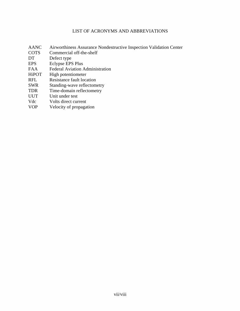
LIST OF ACRONYMS AND ABBREVIATIONS
AANC Airworthiness Assurance Nondestructive Inspection Validation Center COTS Commercial off-the-shelf DT Defect type EPS Eclypse EPS Plus FAA Federal Aviation Administration HiPOT High potentiometer RFL Resistance fault location SWR Standing-wave reflectometry TDR Time-domain reflectometry UUT Unit under test Vdc Volts direct current VOP Velocity of propagation
vii/viii
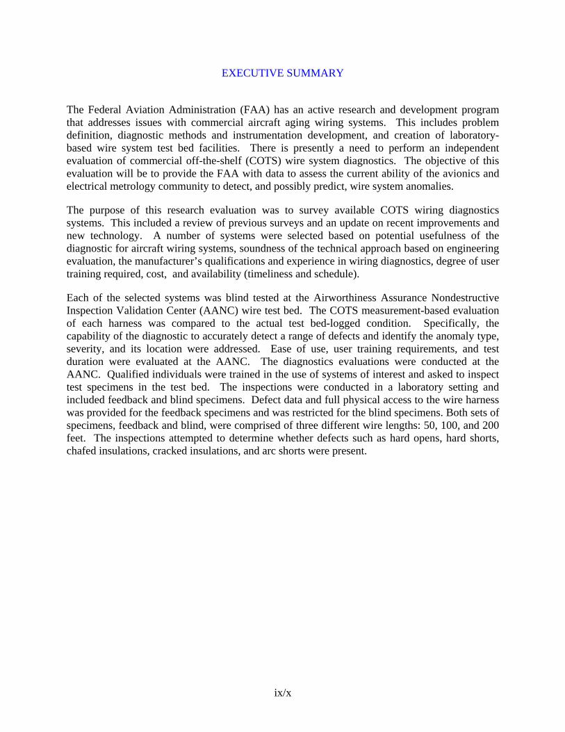
EXECUTIVE SUMMARY
The Federal Aviation Administration (FAA) has an active research and development program that addresses issues with commercial aircraft aging wiring systems. This includes problem definition, diagnostic methods and instrumentation development, and creation of laboratory-based wire system test bed facilities. There is presently a need to perform an independent evaluation of commercial off-the-shelf (COTS) wire system diagnostics. The objective of this evaluation will be to provide the FAA with data to assess the current ability of the avionics and electrical metrology community to detect, and possibly predict, wire system anomalies.
The purpose of this research evaluation was to survey available COTS wiring diagnostics systems. This included a review of previous surveys and an update on recent improvements and new technology. A number of systems were selected based on potential usefulness of the diagnostic for aircraft wiring systems, soundness of the technical approach based on engineering evaluation, the manufacturer’s qualifications and experience in wiring diagnostics, degree of user training required, cost, and availability (timeliness and schedule).
Each of the selected systems was blind tested at the Airworthiness Assurance Nondestructive Inspection Validation Center (AANC) wire test bed. The COTS measurement-based evaluation of each harness was compared to the actual test bed-logged condition. Specifically, the capability of the diagnostic to accurately detect a range of defects and identify the anomaly type, severity, and its location were addressed. Ease of use, user training requirements, and test duration were evaluated at the AANC. The diagnostics evaluations were conducted at the AANC. Qualified individuals were trained in the use of systems of interest and asked to inspect test specimens in the test bed. The inspections were conducted in a laboratory setting and included feedback and blind specimens. Defect data and full physical access to the wire harness was provided for the feedback specimens and was restricted for the blind specimens. Both sets of specimens, feedback and blind, were comprised of three different wire lengths: 50, 100, and 200 feet. The inspections attempted to determine whether defects such as hard opens, hard shorts, chafed insulations, cracked insulations, and arc shorts were present.
ix/x
1. INTRODUCTION.
1.1 PURPOSE.
The purpose of this research evaluation was to survey available commercial off-the-shelf (COTS) wiring diagnostics systems. This included a review of previous surveys and an update on recent improvements and new technology. A number of systems were selected based on potential usefulness of the diagnostic for aircraft wiring systems, soundness of the technical approach based on engineering evaluation, the manufacturer’s qualifications and experience in wiring diagnostics, degree of user training required, cost, and availability (timeliness and schedule).
Each selected system was blind tested at the Airworthiness Assurance Nondestructive Inspection Validation Center (AANC) wire test bed. The evaluator was trained to use the COTS equipment, but did not have prior knowledge of specific harness wire conditions. The COTS measurement-based evaluation of each harness was compared to the actual test bed-logged condition. Specifically, the capability of the diagnostic to accurately detect a range of defects and identify the anomaly type, severity, and its location were addressed. Ease of use, user training requirements, and test duration were evaluated.
1.2 BACKGROUND.
The Federal Aviation Administration (FAA) has an active research and development program that addresses issues with commercial aircraft aging wiring systems. This includes problem definition, diagnostic methods and instrumentation development, and creation of laboratory-based wire system test bed facilities. There is presently a need to perform an independent COTS wire system diagnostics. This evaluation will provide the FAA with data to assess the current ability of the avionics and electrical metrology community to detect, and possibly predict, wire system anomalies.
The AANC facility has a wire laboratory that includes a test bed containing a wide variety of aged (retired) and newly fabricated wire harness types. This facility was used to evaluate several commercial wiring diagnostic systems. The harnesses have naturally occurring and fabricated wire insulation, installation, and continuity anomalies. The aged harnesses were retrieved from Boeing and Douglas, large commercial, passenger-carrying aircraft (Boeing 747, 737, 727, DC-9, and DC-10).
1.3 TEST PLAN.
The test plan consisted of identifying aircraft wiring diagnostic equipment vendors (i.e., original equipment manufacturer, airlines, electronic equipment developer, nondestructive inspection equipment manufacturer), that were commercially available. After the vendors were contacted, a questionnaire was sent to them, and an evaluation, based on the criteria and information from the questionnaire, was done to select appropriate equipment. The equipment had to be commercially available for purchase, be able to find shorts and opens, and be able to determine the location of the defect(s). The ability of the equipment to detect more challenging defects, such as chafed or cracked insulation, was also considered. The manufacturer-provided training had to be short, 1 week or less, and portable equipment was preferred.
1
The diagnostics evaluations were conducted at the AANC wire laboratory. Qualified individuals were trained to use the systems of interest and asked to inspect test specimens in the test bed. Operators were allowed to use the diagnostic system operation manuals and any associated inspection procedures provided by the manufacturer as reference documents to conduct the inspections. The inspections were conducted in a laboratory setting and included feedback and blind specimens. Defect data and full physical access to the wire harness was provided for the feedback specimen and was restricted for the blind specimens. Both sets of specimens, feedback and blind, were comprised of three different wire lengths: 50, 100, and 200 feet. The inspections attempted to determine whether or not the following defects were present:
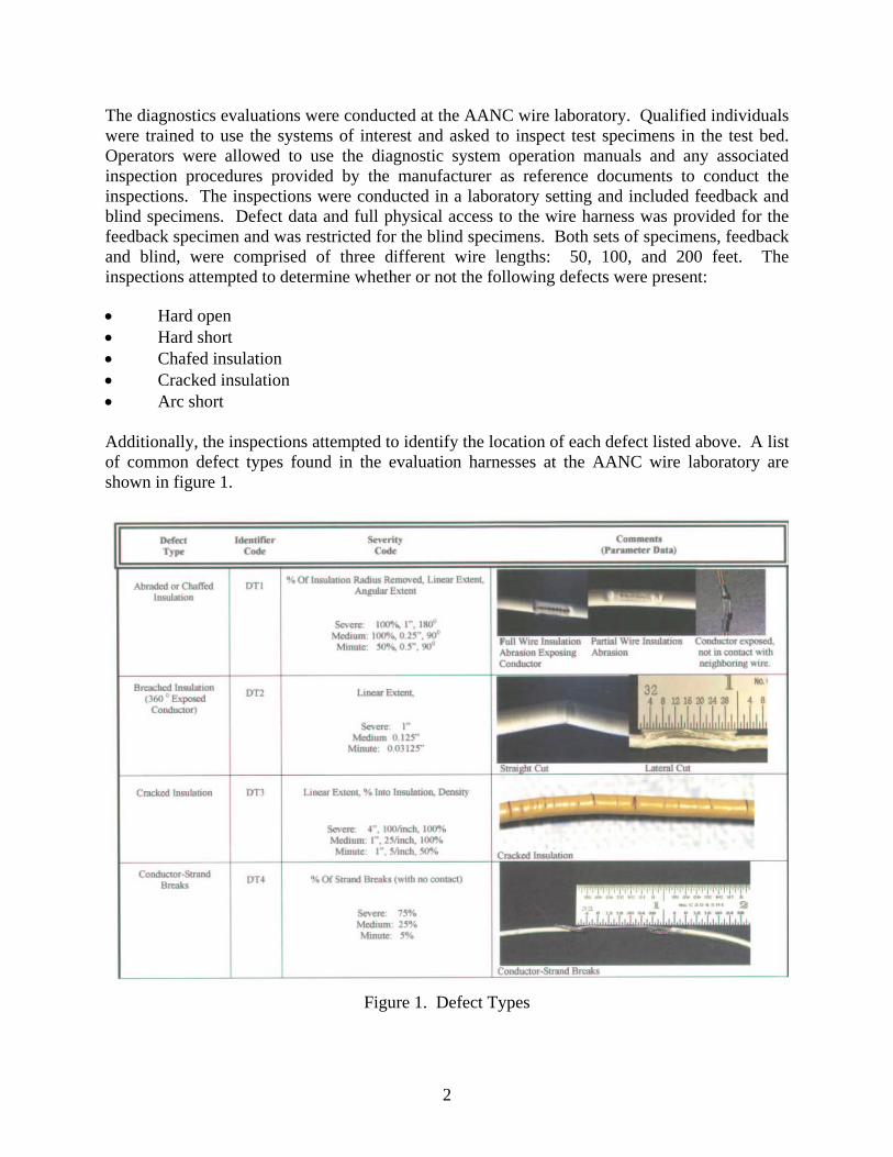
• Hard open • Hard short • Chafed insulation • Cracked insulation • Arc short Additionally, the inspections attempted to identify the location of each defect listed above. A list of common defect types found in the evaluation harnesses at the AANC wire laboratory are shown in figure 1.
Figure 1. Defect Types
2
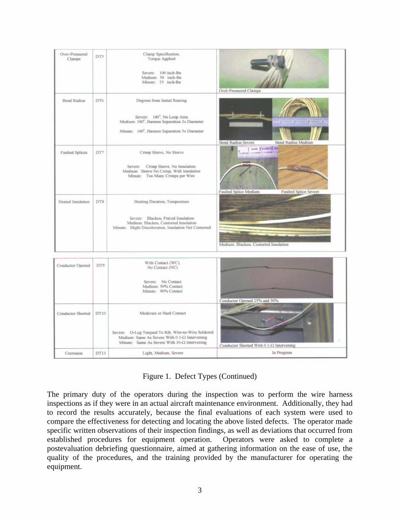
Figure 1. Defect Types (Continued) The primary duty of the operators during the inspection was to perform the wire harness inspections as if they were in an actual aircraft maintenance environment. Additionally, they had to record the results accurately, because the final evaluations of each system were used to compare the effectiveness for detecting and locating the above listed defects. The operator made specific written observations of their inspection findings, as well as deviations that occurred from established procedures for equipment operation. Operators were asked to complete a postevaluation debriefing questionnaire, aimed at gathering information on the ease of use, the quality of the procedures, and the training provided by the manufacturer for operating the equipment.
3
2. DISCUSSION.
This research program required that each system be evaluated and data analyzed, and that a report be developed that included a comparison of measurement-based factors by which the systems could be compared. Specifically, the report addressed the capability of the diagnostic system to accurately detect a range of defects and to identify the anomaly type, severity, and its location. Ease of use, user training requirements, and test duration were evaluated. None of the systems tested were able to detect any type of defects other than opens and shorts, and those defects, by their very nature, did not have severities that could be measured in the ranges of the equipment tested. Thus, there are no severity measures detailed in this report. The number of harnesses and individual wires tested by a given system varied based on the type of technology and implementation of the specific system. Systems that were designed to perform multipoint diagnostics of complete electrical systems, such as the Cable Test, CK Technologies, and DIT-MCO systems, were evaluated using several harnesses and all wires in each harness. Systems that were designed to perform point-to-point diagnostics of electrical systems were evaluated using individual wires specified by the test monitor to reduce the amount of time required to something that could be accomplished within a reasonable time frame. However, there were enough wires included in the testing to provide ample opportunities for success at finding defects, as well as opportunities for making false calls. Thus, there are differences in the number of wires and defects tested between different systems. The performance of each of the systems evaluated on the test bed is presented in this report in four categories: detectable defects detected, detectable defects located, total defects detected, and total defects located. Detectable defects detected refer to the amount of specified defect types detected by the system in the test bed. Detectable defects located refer to the amount of specified defect types that were located in the test bed. Total defects detected refer to the percentage of defects that were found in test bed. Total defects located refer to the percentage of defects that were located in the test bed. 3. EQUIPMENT EVALUATIONS.
3.1 CABLE TEST MPT5000L.
The Cable Test MPT5000L is a resistive-capacitive tester with an added high-voltage, high-potentiometer (HiPOT) insulation tester. The equipment reads precision resistances of the wires in a cable and flags any that exceed a programmable threshold. The MPT5000L also runs a low-voltage insulation current leakage test and reports the integrity of the insulation. The HiPOT test routine consists of charging one conductor to a high voltage (2000 volts direct current (Vdc) in this equipment’s configuration) while grounding the remaining conductors in the cable. The analyzer then monitors for excessive current flow that would indicate an arc from this conductor. This type of test provides electrical stress on the insulation and then tests its voltage hold-off capability. The MPT5000L provides customized tests due to its programming environment. A knowledgeable user may develop specialized test algorithms. During the tests, with a lower level of proficiency on the equipment, the programming was found to be somewhat cumbersome.
4
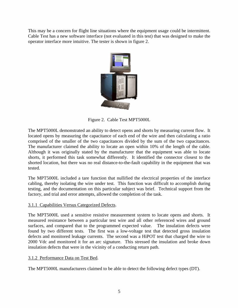
This may be a concern for flight line situations where the equipment usage could be intermittent. Cable Test has a new software interface (not evaluated in this test) that was designed to make the operator interface more intuitive. The tester is shown in figure 2.
Figure 2. Cable Test MPT5000L The MPT5000L demonstrated an ability to detect opens and shorts by measuring current flow. It located opens by measuring the capacitance of each end of the wire and then calculating a ratio comprised of the smaller of the two capacitances divided by the sum of the two capacitances. The manufacturer claimed the ability to locate an open within 10% of the length of the cable. Although it was originally stated by the manufacturer that the equipment was able to locate shorts, it performed this task somewhat differently. It identified the connector closest to the shorted location, but there was no real distance-to-the-fault capability in the equipment that was tested.
The MPT5000L included a tare function that nullified the electrical properties of the interface cabling, thereby isolating the wire under test. This function was difficult to accomplish during testing, and the documentation on this particular subject was brief. Technical support from the factory, and trial and error attempts, allowed the completion of the task. 3.1.1 Capabilities Versus Categorized Defects.
The MPT5000L used a sensitive resistive measurement system to locate opens and shorts. It measured resistance between a particular test wire and all other referenced wires and ground surfaces, and compared that to the programmed expected value. The insulation defects were found by two different tests. The first was a low-voltage test that detected gross insulation defects and monitored leakage currents. The second was a HiPOT test that charged the wire to 2000 Vdc and monitored it for an arc signature. This stressed the insulation and broke down insulation defects that were in the vicinity of a conducting return path. 3.1.2 Performance Data on Test Bed. The MPT5000L manufacturers claimed to be able to detect the following defect types (DT).
5
• DT1—Abraded or chaffed insulation • DT2—Breached insulation (360 degrees exposed conductor) • DT3—Cracked insulation • DT5—Over-pressured clamps • DT—Faulted splice • DT8—Heated insulation • DT9—Open conductors • DT10—Shorted conductors However, this technology only detected continuity defects (DT9 and DT10). These defects are termed the key defects, whereas the insulation and installation defects are termed non-key defects. There were a total of 26 key defects and 62 non-key defects populated on the 19 cables tested. The breakdown of the results for the MPT5000L is shown below: • Detectable defects detected: 100.0% • Detectable defects located: 38.5% • Total defects detected: 34.1% • Total defects located: 36.7% The MPT5000L detected all hard opens and shorts. It located 83.3% (10/12) of the hard opens to within the 10% tolerance, as specified by the company. The short locations were reported as the nearest connector to the defect, but since they were not specified with any particular accuracy, they were not evaluated. 3.1.3 Summary. The MPT5000L readily detected hard opens and shorts. The location of the reported opens was accurate on all of the hard open defects. The location of the shorts was reported by listing the connector closest to the short location. This could be an issue in aircraft wiring systems that may have long runs (e.g., 200 ft or more). The MPT5000L had difficulty finding insulation breach defects. It located a few defects where the insulation was breached and near a return path, as the company described in their defects capability response. An over-pressured clamp and a burned insulation defect were detected during the HiPOT testing. The MPT5000L was claimed to be capable of detecting strand breaks by the manufacturers. A test was performed on a short piece of wire with a resistance of 16 milliohms. As the wire was clipped strand-by-strand, the resistance increased to 22 milliohms. Although the equipment certainly was able to detect this minute increase in resistance, it was not able to discern this defect on 10-ft pieces of wire that had 100 milliohms or more of resistance. The MPT5000L provided a large quantity of data during testing. The operator had some difficulty interpreting this data to detect a particular defect type. When the wires were detected as being shorted to ground, they were also detected as being shorted to any other conductors that were shorted to ground. In this situation, the MPT5000L would also report a short to another conductor that was intentionally shorted to ground. This type of information was confusing at times.
6
Some technical difficulties were experienced such as an input/output board failure that caused many side effect symptoms that were not intuitively related to the problem. The system reported arc shorts that did not exist and other symptoms. A company representative quickly isolated the issue on-site and testing continued. Another technical issue experienced was difficulty in taring the system. The equipment manuals and documentation were used to resolve the problem, but the documentation was limited and did not provide the required assistance. Technical support from the factory was obtained where key information regarding the tare algorithm used within the system was addressed, which corrected all but a couple of the taring issues. 3.2 ECLYPSE ESP PLUS.
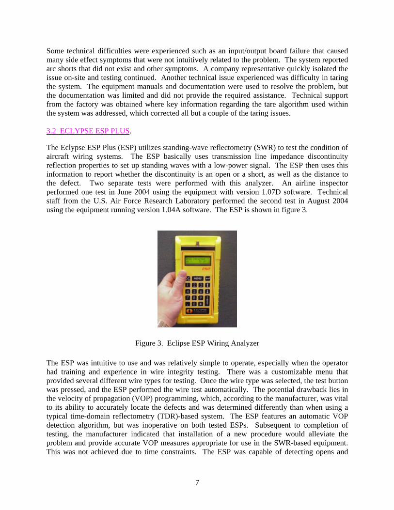
The Eclypse ESP Plus (ESP) utilizes standing-wave reflectometry (SWR) to test the condition of aircraft wiring systems. The ESP basically uses transmission line impedance discontinuity reflection properties to set up standing waves with a low-power signal. The ESP then uses this information to report whether the discontinuity is an open or a short, as well as the distance to the defect. Two separate tests were performed with this analyzer. An airline inspector performed one test in June 2004 using the equipment with version 1.07D software. Technical staff from the U.S. Air Force Research Laboratory performed the second test in August 2004 using the equipment running version 1.04A software. The ESP is shown in figure 3.
Figure 3. Eclipse ESP Wiring Analyzer The ESP was intuitive to use and was relatively simple to operate, especially when the operator had training and experience in wire integrity testing. There was a customizable menu that provided several different wire types for testing. Once the wire type was selected, the test button was pressed, and the ESP performed the wire test automatically. The potential drawback lies in the velocity of propagation (VOP) programming, which, according to the manufacturer, was vital to its ability to accurately locate the defects and was determined differently than when using a typical time-domain reflectometry (TDR)-based system. The ESP features an automatic VOP detection algorithm, but was inoperative on both tested ESPs. Subsequent to completion of testing, the manufacturer indicated that installation of a new procedure would alleviate the problem and provide accurate VOP measures appropriate for use in the SWR-based equipment. This was not achieved due to time constraints. The ESP was capable of detecting opens and
7
shorts in the wiring, but was somewhat limited in the ability to locate both types of defects. No other types of defects were detected. 3.2.1 Capabilities Versus Categorized Defects V1.07D.
The documentation on the ESP claimed that it can detect and locate opens and shorts to within 1 inch. No capabilities in locating insulation defects or installation defects were noted. Based on this information, the ESP was expected to detect and locate DT9 open wires and DT10 shorted wires (common and differential modes). An airline avionics maintenance technician with experience using the ESP conducted the tests at the AANC wiring laboratory. Although a formal response from the manufacturer as to what defects their equipment could detect was not provided, the maintenance technician stated that the ESP was capable of open and short detection as well as the location of those defects. Detection of all other defects was not expected, and the set of wire harnesses tested was limited based on this expectation. 3.2.2 Performance Data on Test Bed.
In the wire harnesses tested with the ESP there were a total of 14 open, short defects, and 32 nondetectable defects. The ESP detected all 14 detectable defects and 1 nondetectable defects, which was a bad splice defect that exhibited an open characteristic. Ten of 14 detectable defects and 1 nondetectable defect were located accurately. For the four inaccurate location reports, a VOP issue was suspected as the cause. The breakdown of the results for the ESP is show below: • Detectable defects detected: 100.0% • Detectable defects located: 71.4% • Total defects detected: 32.6% • Total defects located: 73.3% 3.2.3 Summary.
The ESP detected all opens and shorts in the test bed. The location was reported accurately on several defects where the correct VOP value was used. The test monitor noted that four open defects were detected and displayed by the ESP; however, the technician did not interpret the results as a defect. The ESP reported every test as either an open or a short. Open is, therefore, a normal condition on a disconnected cable. Thus, the operator must know the wire’s length to determine whether there is a defect or not. To further complicate the issue, in cases where a wire was shorted to another wire or to ground, the length of the cable was often reported inaccurately, presumably due to the impedance discontinuity. Thus, the ESP reported the wire as longer than its actual length. Possible solutions are to connect the system to both ends of the wire, or to test each wire pair with its far end in both open and shorted conditions.
An open conductor at a connector is a very common defect found in aircraft wiring systems. During the testing, when a wire possessed an open at the connector on the far end from where the ESP was connected, it reported an open at that far end. However, the technician often did not discern the disconnected connector defect and reported the wire as good. It appears that an appropriate test procedure would require the system be applied to both ends of the cable. The data suggests that the ESP is a useful tool for open and short defect detection. With an improved
8
procedure for VOP calibration, the defect may be accurately located. No other wiring defect types, unless they display open or short characteristics, were detected with the ESP. 3.2.4 Performance Data on Test Bed V1.04A.
In the cable that was tested with the ESP, there were a total of 18 open, short defects, and 27 nondetectable defects. Of these defects, the ESP detected all 18 detectable defects and 1 nondetectable defect, which was a bad splice defect that exhibited an open characteristic. The system was able to locate 11 of the 18 detectable defects and 1 nondetectable defect. The breakdown of the results for the ESP is shown below: • Detectable defects detected: 100.0% • Detectable defects located: 61.1% • Total defects detected: 40.0% • Total defects located: 66.7%
3.2.5 Summary V1.04A.
The ESP system detected all opens and shorts in the test bed. The ESP was able to locate most of these detected defects. The cause for the error in the unlocated defects is unknown. While VOP estimation was an issue in the first test performed by an industry inspector, the VOP did not appear to be the main issue in the second set of tests performed. During the second test, there were a large number of location errors, even though the operators were more experienced with the ESP and were using the correct VOP values determined by other methods. One installation-type defect was found with the ESP, a faulty splice was detected and located; however, that particular splice exhibits open circuit characteristics. No other installation defects (wiring bend radius, over-tightened clamps) or insulation defects (insulation chafing or cracking) were detected. According to the manufacturer, the ESP requires an accurate VOP value to detect defects accurately. This was a vital issue with all the reflectometry-based systems. The ESP unit features an automatic VOP detection tool, but it was inoperative in most cases. It is unknown why, when it did operate, the VOP value was wrong on both ESPs tested under this program. The ESP proved to be a very useful tool for open and short defect detection. However, the location detection capability was somewhat limited, and it is not clear that the limitations were entirely due to VOP issues. No other wiring-type defects, unless they display open or short characteristics, were detected. The manufacturer has other wiring analyzer systems that are claimed to have more capabilities in detecting the challenging defects. 3.3 CKT 1175-10 HIGH-VOLTAGE CIRCUIT ANALYZER.
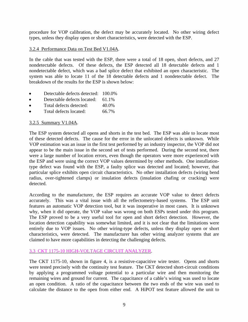
The CKT 1175-10, shown in figure 4, is a resistive-capacitive wire tester. Opens and shorts were tested precisely with the continuity test feature. The CKT detected short-circuit conditions by applying a programmed voltage potential to a particular wire and then monitoring the remaining wires and ground for current. The capacitance of a cable’s wiring was used to locate an open condition. A ratio of the capacitance between the two ends of the wire was used to calculate the distance to the open from either end. A HiPOT test feature allowed the unit to
9
apply a high-voltage stress to the wire to probe more subtle insulation faults. (Note: Up to 1500 Vdc and up to 5 amps could provide a lethal shock if used improperly.)
Figure 4. CKT1175-10 High-Voltage Circuit Analyzer
3.3.1 Capabilities Versus Categorized Defects.
The CKT was expected to detect open and short conditions in both wire-to-wire (differential mode) and wire-to-ground (common mode) wiring. The CKT was expected to locate (as opposed to detect) only opens at a distance down the wire.
3.3.2 Performance Data on Test Bed.
The CKT should be able to detect DT9 open conductor and DT10 shorted conductor defects according to manufacturer’s claim. There were a total of 17 key defects and 61 non-key defects populated on the 20 tested cables. The CKT was able to detect 16 of the 17 key defect types in the test bed. Of those 17 defects, 5 were opens and 12 were shorts. The CKT is capable of locating (as opposed to detecting) open faults only. The CKT located 1 of the 5 documented opens accurately and 1 other non-key defect that exhibited symptoms of an open. The CKT was able to detect 2 of the 61 non-key defects. One detected non-key defect was an over-tightened clamp that exhibited characteristics of a short to ground, hence the detection. The other was a faulty splice that exhibited an open characteristic. The breakdown of the results for the CKT is shown below: • Detectable defects detected: 94.1% • Detectable defects located: 33.3% • Total defects detected: 23.1% • Total defects located: 33.3% 3.3.3 Summary.
The CKT was capable of detecting opens and shorts in the tested aircraft wiring systems. No other defects were detected with the system other than those that exhibited symptoms of opens and shorts. The CKT did not perform very well at locating the defects. The CKT claimed to be
10
capable of locating open faults, but was only able to locate 2 of the 6 conditions to within 18 inches. It was not difficult to operate. The technician was able to adequately operate the CKT with a 2-day training course provided by the manufacturer; however, data interpretation problems occurred. In the test report, one entry that was not clear was “No UUT.” The operator was unable to interpret these entries but noted the anomalies anyway. Both instances of these events involved short circuits to ground. The explanation to the entry is that the system could not resolve the unit under test (UUT) address for the corresponding CKT address. The reason for this was either there is no translation map loaded or the translation map does not contain an entry corresponding to the specified CKT address.
3.4 JOVIAL TEST EQUIPMENT SHORTSTOP.
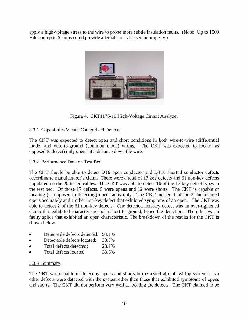
The Jovial Shortstop, shown in figure 5, is a compact, hand-held device that implements TDR technology to diagnose wiring conditions. The Shortstop was very simple to operate, required no formal training other than reviewing the operator’s manual, and provided continuity fault (open or short) detection as well as the location to those faults.
Figure 5. Jovial Test Equipment Shortstop
3.4.1 Capabilities Versus Categorized Defects.
The Shortstop was easy to operate and required 30 minutes or less to learn thoroughly. It had a light emitting diode display that provided the operator with distance information. A tone sounded in the case when a short was detected on the wire under test. No insulation or installation defects were detected with the Shortstop. 3.4.2 Performance Data on Test Bed.
Based on product literature and understanding of the basic principles used, the Shortstop was expected to detect the DT9 open conductor and DT10 shorted conductor. In the wire harnesses tested with the Shortstop, there were a total of 19 open and short defects and 35 nondetectable defects. Of these defects, the Shortstop detected all 19 of the detectable defects and none of the nondetectable defects. Eleven of 19 detectable defects, 6 opens and 13 shorts, were located accurately. The breakdown of the results for the Shortstop is shown below: • Detectable defect detected: 100.0% • Detectable defects located: 57.9%
11
• Total defects detected: 35.2% • Total defects located: 57.9% 3.4.3 Summary.
The Shortstop performed very well and detected all the continuity (open and short) defects. The locating ability of open defects was very good; however, the locating ability on short defects was not as impressive. Only 5 of the 13 short defects were accurately located, and the defect locations were marginal, meaning they were between 12 and 18 inches off. However, the locations were still within the manufacturer’s stated specification of +24 inches for cables that are 10 feet or less. To use the Shortstop effectively, the technician required about 30 minutes to review the operator’s manual. The Shortstop’s simplicity was remarkable. After turning it on, two wires were connected to the circuit under test. The display updated within a second and provided a number. If a defect was present, the number indicated the length (in feet) to the defect. If the cable had no defect, the number matched the length of the cable. Any number shorter than the known wire length indicated an open condition in the wiring. If the Shortstop sounded a tone, then a short had been detected, and once again, the number provided indicated the distance in feet to the defect. Setting the VOP was also very easy. The Shortstop had the same limitations as other TDR equipment primarily related to VOP determination. However, its simplicity made it very easy to estimate a VOP and adjust it by a trial and error method, provided the length of the cable was known. Other technologies have that the same capability provided the length of the cable is known. A key factor with the Shortstop was its cost of $350.00, making it significantly less than the other systems tested. 3.5 PHOENIX AVIATION ARCMAS.
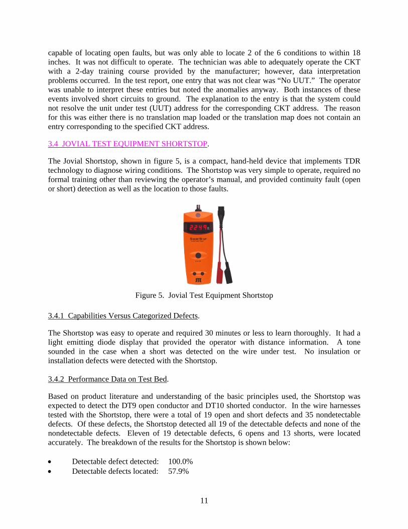
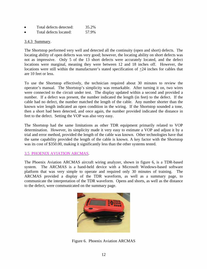
The Phoenix Aviation ARCMAS aircraft wiring analyzer, shown in figure 6, is a TDR-based system. The ARCMAS is a hand-held device with a Microsoft Windows-based software platform that was very simple to operate and required only 30 minutes of training. The ARCMAS provided a display of the TDR waveform, as well as a summary page, to communicate the interpretation of the TDR waveform. Opens and shorts, as well as the distance to the defect, were communicated on the summary page.
Figure 6. Phoenix Aviation ARCMAS
12
3.5.1 Capabilities Versus Categorized Defects.
The ARCMAS was expected to detect and locate continuity defects (opens and shorts). The Phoenix Aviation representatives that provided the training on the equipment did not expect detection of insulation or installation defects. Although Phoenix Aviation provided training, the ARCMAS came with adequate documentation in the operator’s manual to operate it without formal training. 3.5.2 Performance Data on Test Bed.
The ARCMAS can detect DT9 open conductor and DT10 shorted conductor defect types. It should be noted that previous conversations with Phoenix Aviation representatives indicated the ARCMAS was able to detect more than just DT9 and DT10 defect types. The representatives that visited the AANC facility for training on the equipment did not support this claim. In the wire harnesses tested, there were a total of 13 open, short defects, and 31 nondetectable defects. Of these defects, the analyzer detected 12 detectable defects and 1 nondetectable defect, which was a bad splice defect that exhibited an open characteristic. Twelve of 13 detectable defects and 1 nondetectable defect were all located accurately. The breakdown of the results for the ARCMAS is shown below: • Detectable defect detected: 92.1% • Detectable defects located: 91.7% • Total defects detected: 29.6% • Total defects located: 92.3% 3.5.3 Summary.
The ARCMAS performed very well at detecting continuity (open and short) defects, as well as having the ability to locate both opens and shorts. The ARCMAS was able to detect one installation defect, a DT7 faulty splice that exhibited an open condition, but was unable to detect any other installation or insulation defects. There were a few occasions where the TDR waveform displayed indications of impedance changes that might correlate with certain types of defects; however, many other false indications were present throughout the testing. The ARCMAS suffered several problems that were most likely software-related. On many occasions, an error message of “High Impedance at O” was displayed on the summary page. This problem was explained during the training. The “Event Screen” displayed more correct information; therefore, it was assumed that the issue could be readily corrected. The software often reported an excessively long length of cable. This was related to two different conditions: (1) if the system was probing wiring that was shorted, it often gave a longer than actual length, or (2) the system often misinterpreted the sharp impedance rise at the end of the cable and instead reported longer reflections. A problem with software lockups was experienced with the hardware that was tested. The ARCMAS would lockup into a seemingly infinite software loop without a method of interrupting the loop. The screen would not accept any inputs and removing the battery to reboot the system did not help. The ARCMAS required a very long wait to correct itself.
13
3.6 THE DIT-MCO MODEL 2135.
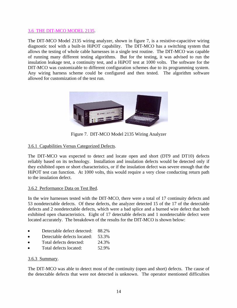
The DIT-MCO Model 2135 wiring analyzer, shown in figure 7, is a resistive-capacitive wiring diagnostic tool with a built-in HiPOT capability. The DIT-MCO has a switching system that allows the testing of whole cable harnesses in a single test routine. The DIT-MCO was capable of running many different testing algorithms. But for the testing, it was advised to run the insulation leakage test, a continuity test, and a HiPOT test at 1000 volts. The software for the DIT-MCO was customizable to different configuration schemes due to its programming system. Any wiring harness scheme could be configured and then tested. The algorithm software allowed for customization of the test run.
Figure 7. DIT-MCO Model 2135 Wiring Analyzer
3.6.1 Capabilities Versus Categorized Defects.
The DIT-MCO was expected to detect and locate open and short (DT9 and DT10) defects reliably based on its technology. Installation and insulation defects would be detected only if they exhibited open or short characteristics, or if the insulation defect was severe enough that the HiPOT test can function. At 1000 volts, this would require a very close conducting return path to the insulation defect. 3.6.2 Performance Data on Test Bed.
In the wire harnesses tested with the DIT-MCO, there were a total of 17 continuity defects and 53 nondetectable defects. Of these defects, the analyzer detected 15 of the 17 of the detectable defects and 2 nondetectable defects, which were a bad splice and a burned wire defect that both exhibited open characteristics. Eight of 17 detectable defects and 1 nondetectable defect were located accurately. The breakdown of the results for the DIT-MCO is shown below: • Detectable defect detected: 88.2% • Detectable defects located: 53.3% • Total defects detected: 24.3% • Total defects located: 52.9% 3.6.3 Summary.
The DIT-MCO was able to detect most of the continuity (open and short) defects. The cause of the detectable defects that were not detected is unknown. The operator mentioned difficulties
14
with programming the equipment and interpreting the test results may have had an effect; however, three tests were implemented on various cables. Three days of on-site training was provided by a DIT-MCO representative, but due to the very intricate programming variables and complex testing capabilities, it remained difficult to program. The manufacturer provided technical support for the programming, and the results interpretation issues were eventually resolved. Thus, the programming and results interpretation issues were ruled out as a cause for the nondetects of detectable defects. The DIT-MCO was able to locate approximately half of the detected defects. Of the defects that were not located accurately, several were short circuit to ground defects. Some of these defects were wires that were only accessible on one side, and the DIT-MCO did not try to locate defects in those wires. The DIT-MCO was able to detect one installation defect, a DT7 (faulty splice) and one insulation defect, a DT8 (burned wire). Each of these defects exhibited an open characteristic. No other insulation or installation defects were detected. 3.7 THE 3M COMPANY 900AST.
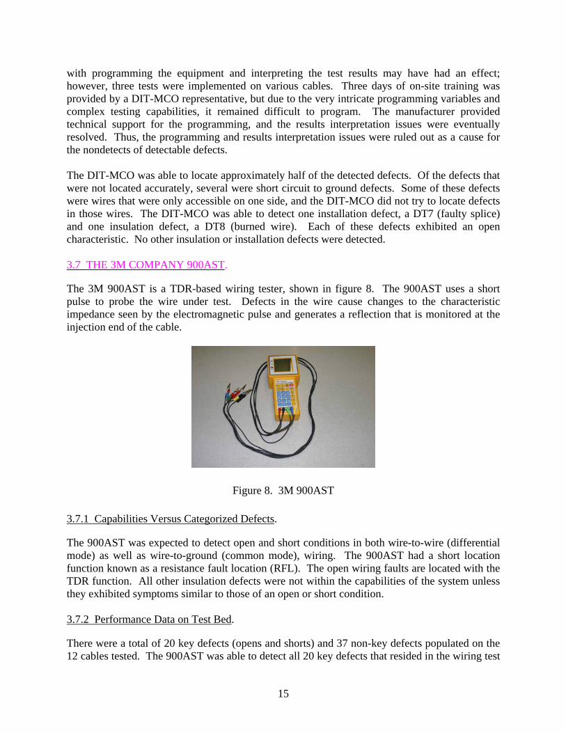
The 3M 900AST is a TDR-based wiring tester, shown in figure 8. The 900AST uses a short pulse to probe the wire under test. Defects in the wire cause changes to the characteristic impedance seen by the electromagnetic pulse and generates a reflection that is monitored at the injection end of the cable.
Figure 8. 3M 900AST 3.7.1 Capabilities Versus Categorized Defects.
The 900AST was expected to detect open and short conditions in both wire-to-wire (differential mode) as well as wire-to-ground (common mode), wiring. The 900AST had a short location function known as a resistance fault location (RFL). The open wiring faults are located with the TDR function. All other insulation defects were not within the capabilities of the system unless they exhibited symptoms similar to those of an open or short condition. 3.7.2 Performance Data on Test Bed.
There were a total of 20 key defects (opens and shorts) and 37 non-key defects populated on the 12 cables tested. The 900AST was able to detect all 20 key defects that resided in the wiring test
15
bed. Of those 20 defects, 6 were opens and 14 were shorts. The 900AST located 9 of the 14 documented shorts accurately with the RFL and all 6 open faults with the TDR function. However, the system was not able to detect any of the insulation and installation non-key defects. The breakdown of the results for the 900AST is shown below: • Detectable defects detected: 100.0% • Detectable defects located: 75.0% • Total defects detected: 35.1% • Total detected defects located: 75.0% 3.7.3 Summary.
The 900AST detected all continuity faults (opens and shorts). The 900AST was able to locate 9 of 14 short conditions, although its performance was marginal. The 900AST was able to locate the open defects accurately using the TDR function, although this requires interpretation of the TDR waveform. The unit located all six defects with the TDR technology. Defect location tolerance was +18 inches. According to the manufacturer, an experienced technician requires less than 1 hour’s training before operating the 900AST. The training provided to AANC personnel was 2 days. One notable feature was its ability to locate shorted wiring. The 900AST used a good reference set of wiring in a special wiring configuration that enables it to calculate the location of the short. Most of the equipment tested can perform the distance to open calculations fairly readily, but the short location algorithms were more challenging. 3.8 THE NORTHROP GRUMMAN AMWIT 1000.
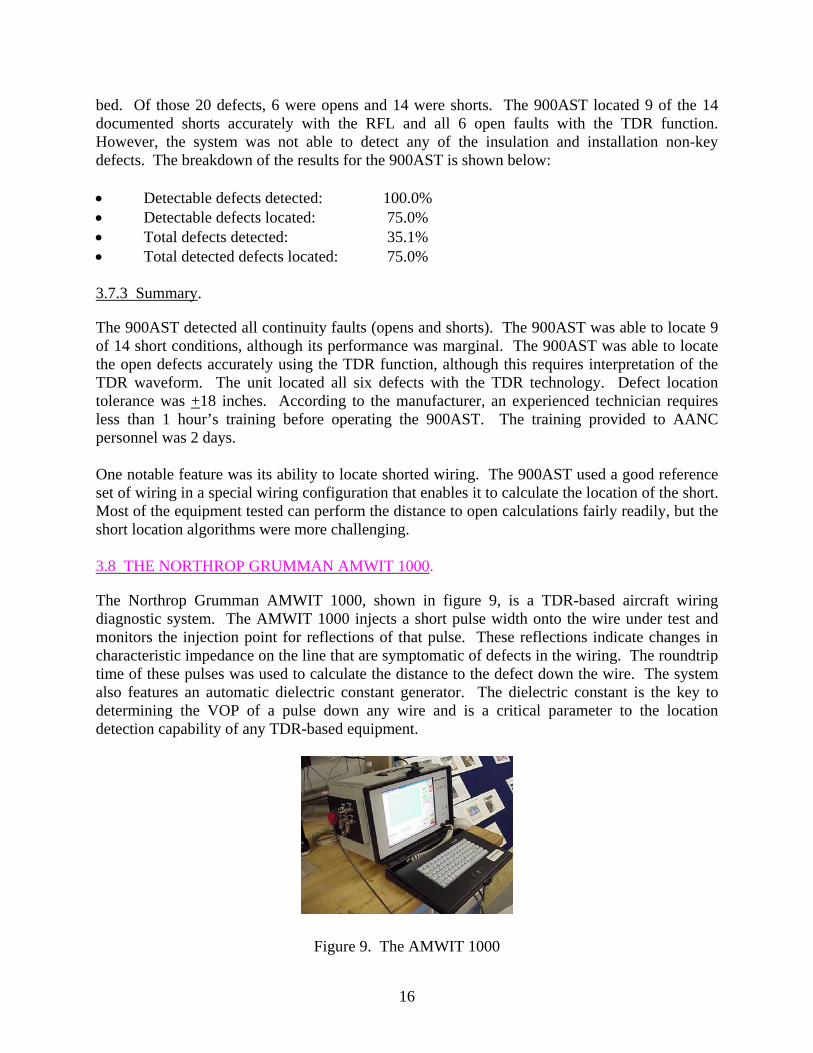
The Northrop Grumman AMWIT 1000, shown in figure 9, is a TDR-based aircraft wiring diagnostic system. The AMWIT 1000 injects a short pulse width onto the wire under test and monitors the injection point for reflections of that pulse. These reflections indicate changes in characteristic impedance on the line that are symptomatic of defects in the wiring. The roundtrip time of these pulses was used to calculate the distance to the defect down the wire. The system also features an automatic dielectric constant generator. The dielectric constant is the key to determining the VOP of a pulse down any wire and is a critical parameter to the location detection capability of any TDR-based equipment.
Figure 9. The AMWIT 1000
16
3.8.1 Capabilities Versus Categorized Defects.
A TDR-based system is, theoretically, capable of locating chafing defects in aircraft wiring due to the changes in characteristic impedance that these defects cause. However, there are other environmental conditions that could cause similar changes. Varying gaps between the conductors, conductors approaching bulkheads, and branching conductors are all examples of normal conditions that cause similar changes in the characteristic impedance of the wiring. Another key issue is related to the size of the defect to be detected. To detect small defects, a very short pulse width is required, which implies higher-frequency content pulses that are difficult to propagate down a pair of discrete wires. The AMWIT 1000 system was expected to detect and locate opens and shorts (continuity defects), as well as chafes in the wiring insulation. 3.8.2 Performance Data on Test Bed.
In the 11 wire harnesses tested with the AMWIT 1000, there were 5 open defects and 13 short defects. There were 27 other non-key defects representing the installation and insulation defects present in the cabling as well. The AMWIT 1000 detected all 18 continuity defects, as was expected. The system located 17 of the 18 defects accurately. One of the 27 non-key defects in the tested cabling was detected and located. This particular defect, although an installation defect (bad splice), exhibited an open condition. The breakdown of the results for the AMWIT 1000 is shown below: • Detectable defects detected: 100.0% • Detectable defects located: 94.4% • Total defects detected: 42.2% • Total defects located: 94.7% 3.8.3 Summary.
The AMWIT 1000 detected all continuity defects. All but one of these detected continuity defects were also located to within 18 inches. The operator did not report any anomalies in the test results that could be correlated to any of the insulation or installation defects. The installation defect that was detected was a bad splice that exhibited symptoms of an open conductor. Otherwise, the AMWIT 1000 did not produce a discernable indication of any other defects. During observation of the testing procedure, it was noticed that the operator frequently needed to correct the location mark in the faultfinding tool results. The AMWIT 1000 often selected an errant location for the fault, but the operator corrected this with his own interpretation of the waveform. This suggested that an experienced operator improved the locating abilities of the equipment. The system was easily operated and required approximately 4 hours of training, providing the technician had a basic understanding of TDR technology. 4. COMPARISONS AND EVALUATIONS.
Table 1 lists the details of the equipment and provides a means of rapidly comparing detectable defects, technologies, and performance of all units tested. All units tested were consistent in
17
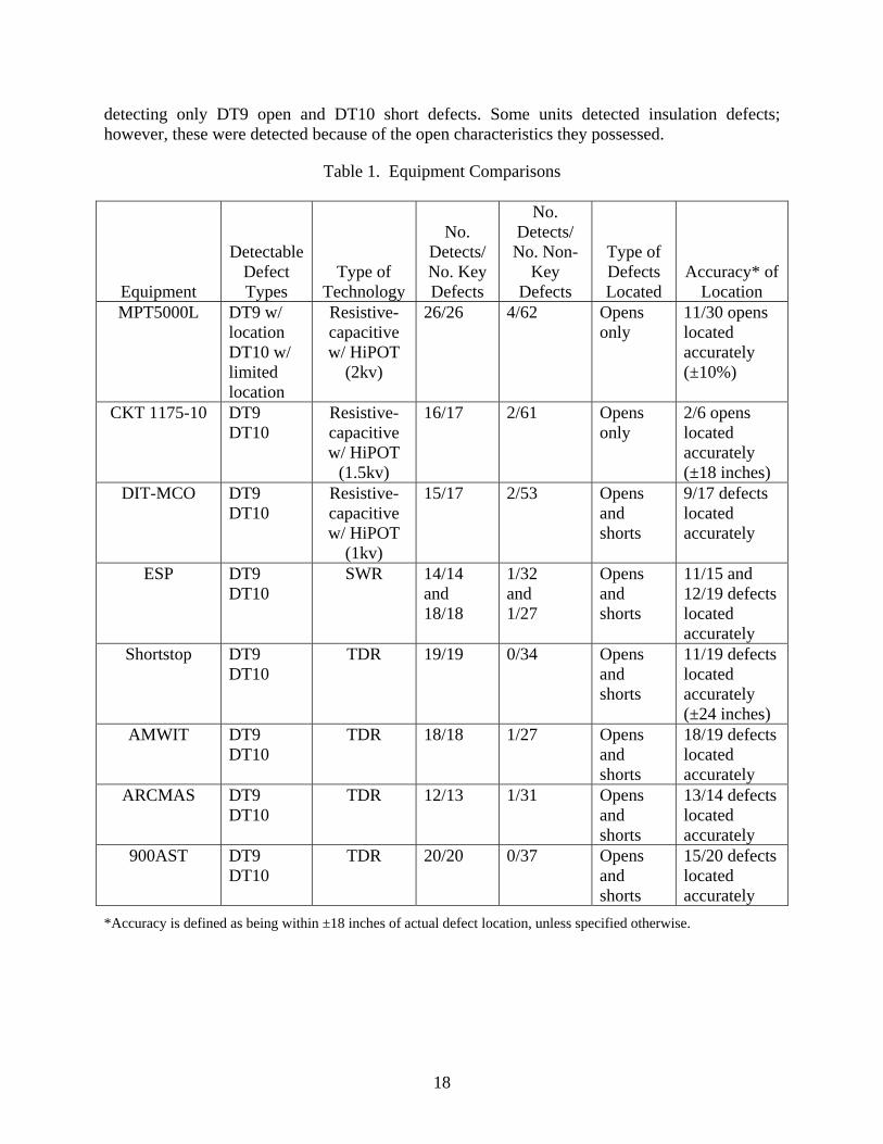
detecting only DT9 open and DT10 short defects. Some units detected insulation defects; however, these were detected because of the open characteristics they possessed.
Table 1. Equipment Comparisons
Equipment
Detectable Defect Types
Type of Technology
No. Detects/ No. Key Defects
No. Detects/ No. Non-
Key Defects
Type of Defects Located
Accuracy* of Location
MPT5000L DT9 w/ location DT10 w/ limited location
Resistive-capacitive w/ HiPOT
(2kv)
26/26 4/62 Opens only
11/30 opens located accurately (±10%)
CKT 1175-10 DT9 DT10
Resistive-capacitive w/ HiPOT
(1.5kv)
16/17 2/61 Opens only
2/6 opens located accurately (±18 inches)
DIT-MCO DT9 DT10
Resistive-capacitive w/ HiPOT
(1kv)
15/17 2/53 Opens and shorts
9/17 defects located accurately
ESP DT9 DT10
SWR 14/14 and 18/18
1/32 and 1/27
Opens and shorts
11/15 and 12/19 defects located accurately
Shortstop DT9 DT10
TDR 19/19 0/34 Opens and shorts
11/19 defects located accurately (±24 inches)
AMWIT DT9 DT10
TDR 18/18 1/27 Opens and shorts
18/19 defects located accurately
ARCMAS DT9 DT10
TDR 12/13 1/31 Opens and shorts
13/14 defects located accurately
900AST DT9 DT10
TDR 20/20 0/37 Opens and shorts
15/20 defects located accurately
*Accuracy is defined as being within ±18 inches of actual defect location, unless specified otherwise.
18
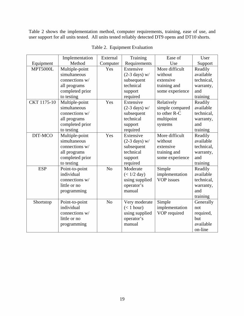
Table 2 shows the implementation method, computer requirements, training, ease of use, and user support for all units tested. All units tested reliably detected DT9 opens and DT10 shorts.
Table 2. Equipment Evaluation
Equipment Implementation
Method External
Computer Training
Requirements Ease of
Use User
Support MPT5000L Multiple-point
simultaneous connections w/ all programs completed prior to testing
Yes Extensive (2-3 days) w/ subsequent technical support required
More difficult without extensive training and some experience
Readily available technical, warranty, and training
CKT 1175-10 Multiple-point simultaneous connections w/ all programs completed prior to testing
Yes Extensive (2-3 days) w/ subsequent technical support required
Relatively simple compared to other R-C multipoint systems
Readily available technical, warranty, and training
DIT-MCO Multiple-point simultaneous connections w/ all programs completed prior to testing
Yes Extensive (2-3 days) w/ subsequent technical support required
More difficult without extensive training and some experience
Readily available technical, warranty, and training
ESP Point-to-point individual connections w/ little or no programming
No Moderate (< 1/2 day) using supplied operator’s manual
Simple implementation VOP issues
Readily available technical, warranty, and training
Shortstop Point-to-point individual connections w/ little or no programming
No Very moderate (< 1 hour) using supplied operator’s manual
Simple implementation VOP required
Generally not required, but available on-line
19
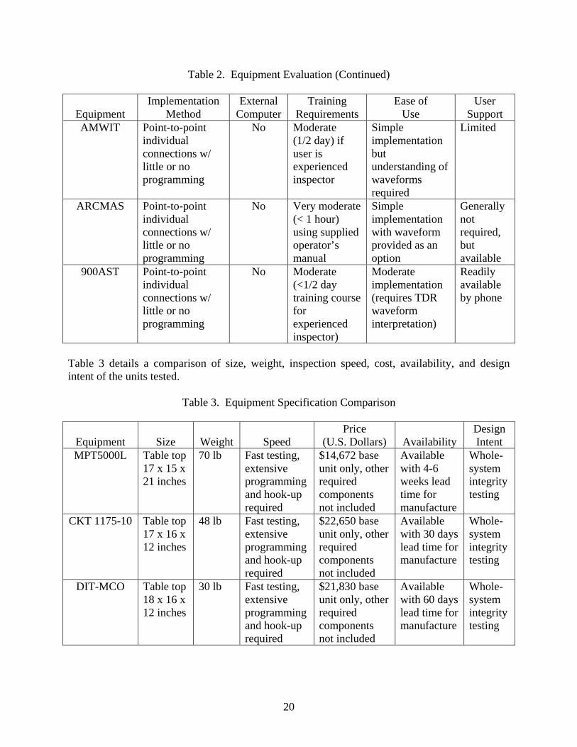
Table 2. Equipment Evaluation (Continued)
Equipment Implementation
Method External
Computer Training
Requirements Ease of
Use User
Support AMWIT Point-to-point
individual connections w/ little or no programming
No Moderate (1/2 day) if user is experienced inspector
Simple implementation but understanding of waveforms required
Limited
ARCMAS Point-to-point individual connections w/ little or no programming
No Very moderate (< 1 hour) using supplied operator’s manual
Simple implementation with waveform provided as an option
Generally not required, but available
900AST Point-to-point individual connections w/ little or no programming
No Moderate (<1/2 day training course for experienced inspector)
Moderate implementation (requires TDR waveform interpretation)
Readily available by phone
Table 3 details a comparison of size, weight, inspection speed, cost, availability, and design intent of the units tested.
Table 3. Equipment Specification Comparison
Equipment Size Weight Speed Price
(U.S. Dollars) Availability Design Intent
MPT5000L Table top 17 x 15 x 21 inches
70 lb Fast testing, extensive programming and hook-up required
$14,672 base unit only, other required components not included
Available with 4-6 weeks lead time for manufacture
Whole-system integrity testing
CKT 1175-10 Table top 17 x 16 x 12 inches
48 lb Fast testing, extensive programming and hook-up required
$22,650 base unit only, other required components not included
Available with 30 days lead time for manufacture
Whole-system integrity testing
DIT-MCO Table top 18 x 16 x 12 inches
30 lb Fast testing, extensive programming and hook-up required
$21,830 base unit only, other required components not included
Available with 60 days lead time for manufacture
Whole-system integrity testing
20
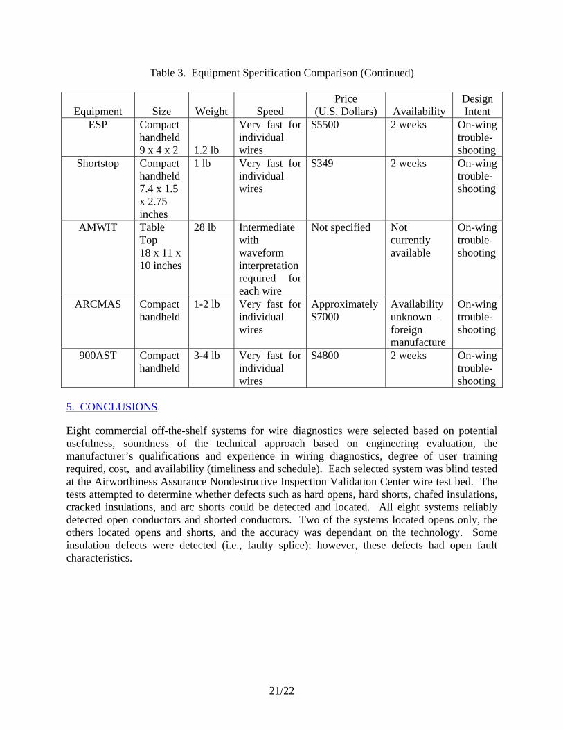
Table 3. Equipment Specification Comparison (Continued)
Equipment Size Weight Speed Price
(U.S. Dollars) Availability Design Intent
ESP Compact handheld 9 x 4 x 2 1.2 lb
Very fast for individual wires
$5500 2 weeks On-wing trouble-shooting
Shortstop Compact handheld 7.4 x 1.5 x 2.75 inches
1 lb Very fast for individual wires
$349 2 weeks On-wing trouble-shooting
AMWIT Table Top 18 x 11 x 10 inches
28 lb Intermediate with waveform interpretation required for each wire
Not specified Not currently available
On-wing trouble-shooting
ARCMAS Compact handheld
1-2 lb Very fast for individual wires
Approximately $7000
Availability unknown – foreign manufacture
On-wing trouble-shooting
900AST Compact handheld
3-4 lb Very fast for individual wires
$4800 2 weeks On-wing trouble-shooting
5. CONCLUSIONS.
Eight commercial off-the-shelf systems for wire diagnostics were selected based on potential usefulness, soundness of the technical approach based on engineering evaluation, the manufacturer’s qualifications and experience in wiring diagnostics, degree of user training required, cost, and availability (timeliness and schedule). Each selected system was blind tested at the Airworthiness Assurance Nondestructive Inspection Validation Center wire test bed. The tests attempted to determine whether defects such as hard opens, hard shorts, chafed insulations, cracked insulations, and arc shorts could be detected and located. All eight systems reliably detected open conductors and shorted conductors. Two of the systems located opens only, the others located opens and shorts, and the accuracy was dependant on the technology. Some insulation defects were detected (i.e., faulty splice); however, these defects had open fault characteristics.
21/22