d:old pcmanualeman.inlucruarmman5522man5522 02 15...
TRANSCRIPT

HI 5521 & HI 5522pH/mV/ISE/Temperature/
Conductivity/Resistivity/TDS/Salinity
Bench Meters
Instruction Manual
www.hannainst .comPrinted in ROMANIA
Hanna Instruments Inc.Highland Industrial Park584 Park East DriveWoonsocket, RI 02895 USA
Technical Support for CustomersTel. (800) 426 6287Fax (401) 765 7575E-mail [email protected]
Local Sales and Customer Service Office
MAN5522 02/15

WARRANTY
Dear Customer,
Thank you for choosing a Hanna Instruments product.
Please read this instruction manual carefully before using these instruments. This manual will provide youwith the necessary information for correct use of these instruments, as well as a precise idea of theirversatility.
If you need additional technical information, do not hesitate to e-mail us at [email protected] or view ourworldwide contact list at www.hannainst.com.
HI 5521 and HI 5522 are guaranteed for two years against defects in workmanship and materials when usedfor their intended purpose and maintained according to instructions. Electrodes and probes are guaranteed forsix months. This warranty is limited to repair or replacement free of charge.
Damage due to accidents, misuse, tampering or lack of prescribed maintenance is not covered.
If service is required, contact the dealer from whom you purchased the instrument. If under warranty, reportthe model number, date of purchase, serial number and the nature of the problem. If the repair is not coveredby the warranty, you will be notified of the charges incurred. If the instrument is to be returned to HannaInstruments, first obtain a Returned Goods Authorization number from the Technical Service department andthen send it with shipping costs prepaid. When shipping any instrument, make sure it is properly packed forcomplete protection.
To validate your warranty, fill out and return the enclosed warranty card within 14 days from the date ofpurchase.
All rights are reserved. Reproduction in whole or in part is prohibited without the written consent of the copyright owner.
OTHER ACCESSORIES
HI 710005/8 Voltage adapter from 115 Vac / 12 Vdc 800 mA (USA plug)
HI 710006/8 Voltage adapter from 230 Vac / 12 Vdc 800 mA (European plug)
HI 76404W Electrode holder
HI 8427 pH and ORP electrode simulator with 1 m (3.3') coaxial cable ending in female BNCconnectors
HI 931001 pH and ORP electrode simulator with LCD and 1 m (3.3') coaxial cable ending in female BNCconnectors
HI 76312 Platinum 4-ring conductivity/TDS probe with temperature sensor and 1 m (3.3') cable
HI 7662-W Temperature probe with 1 m (3.3') cable
HI 92000 Windows® compatible software
HI 920013 USB cable
RECOMMENDATIONS FOR USERS
Before using these products, make sure they are entirely suitable for the environment in which they are used.
Operation of these instruments in residential areas could cause unacceptable interferences to radio and TVequipment, requiring the operator to follow all necessary steps to correct interferences.
The glass bulb at the end of the pH electrode is sensitive to electrostatic discharges. Avoid touching this glassbulb at all times.
Any variation introduced by the user to the supplied equipment may degrade the instruments’ EMCperformance.
To avoid electrical shock, do not use these instruments when voltages at the measurement surface exceed24 Vac or 60 Vdc.
To avoid damage or burns, do not perform any measurement in microwave ovens.
Hanna Instruments reserves the right to modify the design, construction or appearance of it’s products withoutadvance notice.
3
TABLE OF CONTENTS
WARRANTY ............................................................................................................................................. 2PRELIMINARY EXAMINATION.................................................................................................................... 4GENERAL DESCRIPTION ........................................................................................................................... 5FUNCTIONAL DESCRIPTION ...................................................................................................................... 6SPECIFICATIONS ...................................................................................................................................... 8OPERATIONAL GUIDE ............................................................................................................................. 1 1DISPLAYING MODES .............................................................................................................................. 1 2SYSTEM SETUP ..................................................................................................................................... 1 5CHANNEL SELECTION ............................................................................................................................ 2 1pH SETUP ............................................................................................................................................ 2 2mV SETUP ............................................................................................................................................ 3 5ISE SETUP (HI 5522 only) .................................................................................................................... 3 7pH CALIBRATION ................................................................................................................................... 4 5pH MEASUREMENT ............................................................................................................................... 4 9mV & Relative mV MEASUREMENTS ...................................................................................................... 5 1ISE CALIBRATION (HI 5522 only) .......................................................................................................... 5 3ISE MEASUREMENT (HI 5522 only) ...................................................................................................... 5 6CONDUCTIVITY SETUP ........................................................................................................................... 6 2RESISTIVITY SETUP ............................................................................................................................... 7 6TDS SETUP ........................................................................................................................................... 7 8SALINITY SETUP .................................................................................................................................... 8 0CONDUCTIVITY CALIBRATION ................................................................................................................. 8 2CONDUCTIVITY MEASUREMENT ............................................................................................................. 8 4USP EVALUATION .................................................................................................................................. 8 5RESISTIVITY MEASUREMENT ................................................................................................................. 8 9TDS MEASUREMENT ............................................................................................................................. 9 0SALINITY CALIBRATION .......................................................................................................................... 9 1SALINITY MEASUREMENT ...................................................................................................................... 9 2TEMPERATURE CALIBRATION ................................................................................................................. 9 3LOGGING .............................................................................................................................................. 9 4PC INTERFACE ...................................................................................................................................... 9 7ADDITIONAL INFORMATION ................................................................................................................... 9 8pH BUFFER TEMPERATURE DEPENDENCE ............................................................................................. 1 0 1EC PROBE USE AND MAINTENANCE ...................................................................................................... 1 0 2ELECTRODE CONDITIONING AND MAINTENANCE ................................................................................... 1 0 3TROUBLESHOOTING GUIDE ................................................................................................................. 1 0 5TEMPERATURE CORRELATION FOR pH SENSITIVE GLASS ........................................................................ 1 0 7ACCESSORIES ...................................................................................................................................... 1 0 8
114
ORP ELECTRODES
HI 3131B
Glass body, refillable, combination platinum ORP electrode.
Use: titration.
HI 3230B
Plastic body, gel filled, combination platinum ORP electrode.
Use: general purpose.
HI 4430B
Plastic body, gel filled, combination gold ORP electrode.
Use: general purpose.
Consult the Hanna General Catalog for more electrodes with screw-type or BNC connectors.
EXTENSION CABLE FOR SCREW-TYPE ELECTRODES(SCREW TO BNC ADAPTER)
HI 7855/1 Extension cable 1 m (3.3') longHI 7855/3 Extension cable 3 m (9.9') long
CONNECT TO
SCREW TYPE
ELECTRODES
CONNECT TO THE
BNC SOCKET
OF THE METER
HI 7855 SERIES CABLE CONNECTORSCONNECTOR AND 3.0 mm (0.12") CABLE WITH BNC

4
Remove the instrument from the packing material and examine it carefully to make sure that no damage hasoccurred during shipping. If there is any damage, notify your Dealer or the nearest Hanna Customer ServiceCenter.
The meters are supplied complete with:
• HI 1131B Glass-body Combination pH Electrode
• HI 76312 Four-ring Conductivity Probe with built-in temperature sensor and ID
• HI 7662-W Temperature probe
• HI 7082S Electrolyte solution
• HI 76404W Electrode Holder
• pH and Conductivity Calibration Solutions Kit
• One capillary dropper pipette
• 12 Vdc Power Adapter
• Instruction Manual
HI 5521-01 and HI 5522-01 are supplied with 12 Vdc/115 Vac adapter.
HI 5521-02 and HI 5522-02 are supplied with 12 Vdc/230 Vac adapter.
Note: Save all packing material until you are sure that the instrument works properly. Any defective itemmust be returned in the original packing with the supplied accessories.
PRELIMINARY EXAMINATION
113
FC 200B
Plastic body, open junction, conical, Viscolene, non refillable, combination pH electrode.
Use: meat & cheese.
FC 210B
Glass body, double junction, conical, Viscolene, non refillable, combination pH electrode.
Use: milk, yogurt.
FC 220B
Glass body, triple ceramic, single junction, refillable, combination pH electrode.
Use: food processing.
FC 911B
Plastic body, double junction, refillable with built-in amplifier, combination pH electrode.
Use: very high humidity.

5
GENERAL DESCRIPTION
HI 5521 and HI 5522 are professional bench meters with color graphic LCD for pH, ORP (Oxidation ReductionPotential), ISE (HI 5522 only), conductivity, resistivity, TDS, salinity and temperature measurements.
The display can be configured as a single channel or dual channel display in various modes: Basic informationonly, GLP information, Graph and Log History mode.
The main features of the instruments are:
• Two input channels: one for potentiometric sensors, the other for electrolytic conductivity;
• Capacitive touch keypad;
• Eight measurement parameters: pH, mV, ISE (HI 5522 only), conductivity, resistivity, TDS, salinity andtemperature;
• Dedicated Help key with contextual message;
• Manual selection, automatic and semiautomatic pH calibration in up to five points, with standard (1.68,3.00, 4.01, 6.86, 7.01, 9.18, 10.01 and 12.45) and custom buffers (up to five custom buffers);
• Manual Selection and Custom Standard ISE calibration in up to five points, with standard (up to seven standardsolutions for each measurement unit) and custom solutions (up to five custom solutions), with or withouttemperature compensation (HI 5522 only);
• Application for water for injection follows the USP <645> protocol;
• Conductivity probe automatic recognition;
• Automatic or custom standard conductivity calibration in up to four points, probe offset calibration;
• Single point salinity calibration (Percent Scale only);
• AutoHold feature to freeze first stable reading on the LCD;
• Two selectable alarm limits (for pH, mV, ISE, conductivity, resistivity, TDS, salinity);
• Three selectable logging modes: Automatic, Manual, AutoHold logging;
• Continuous Lot logging directly on meter, with selectable log interval: Store up to 100,000 total data points;
• Up to 100 logging lots for automatic or manual modes and up to 200 USP reports, up to 100 ISE methodsreports;
• Selectable sampling period feature for automatic logging;
• Basic Measurement can be viewed with detailed GLP information, or with a Graph or a Log History (whilecontinuously logging);
• Online and offline graph;
• Large color backlight graphic LCD (240 x 320 pixels) with user selectable color palette;
• PC interface via USB; download logged data to PC or use for Real time logging (HI 92000 PC applicationrequired);
• Profile feature: store up to five different user setup on each channel.
112
HI 2031B
Glass body, semi-micro, conical, refillable, combination pH electrode.
Use: semi-solid products.
HI 1332B
Plastic body, double junction, refillable, combination pH electrode.
Use: general purpose.
HI 1413B
Glass body, single junction, flat tip, Viscolene, non-refillable, combination pH electrode.
Use: surface measurement.
FC 100B
Plastic body, double junction, refillable, combination pH electrode.
Use: general purpose for food industry.
6
HI 5521/ HI 5522 DESCRIPTION
FRONT PANEL
1) Liquid Crystal Display (LCD)
2) Capacitive touch keypad
3) ON/OFF switch
4) Power adapter socket
5) USB connector
6) BNC electrode connector for pH/ORP/ISE measurements
7) Temperature probe socket
8) Reference input socket
9) Conductivity probe connector
FUNCTIONAL DESCRIPTION
REAR PANEL
111
HI 1131B
Glass body, double junction, refillable, combination pH electrode.
Use: general purpose.
HI 1330B
Glass body, semi-micro, single junction, refillable, combination pH electrode.
Use: laboratory, vials.
HI 1331B
Glass body, semi-micro, single junction, refillable, combination pH electrode.
Use: flasks.
HI 1230B
Plastic body, double junction, gel filled, combination pH electrode.
Use: general, field.

7
KEYBOARD DESCRIPTION
FUNCTION KEYS
VIRTUAL KEYS
The upper row keys are assigned to the virtual keys placed on the bottom of the LCD, which allow you toperform the displayed function, depending on the current menu (e.g. , and inMeasure mode).
Note: All the virtual keys are assigned to the highlighted channel (highlighted with key).
LCD GENERAL DESCRIPTION
To enter/exit calibration mode;
To select the desired measurement mode, pH, mV, Rel mV, ISE (HI 5522 only), Conductivity,Resistivity, TDS, Salinity;
To enter Setup (System Setup, pH Setup, mV Setup, ISE Setup (HI 5522 only), Conductivity
Setup, Resistivity Setup , TDS Setup or Salinity Setup) and to access Log Recall function;
To obtain general information about the selected option/operation.
110
pH ELECTRODES
All electrodes part numbers ending in B are supplied with a BNC connector and 1 m (3.3') cable, as shownbelow:
HI 1043B
Glass body, double junction, refillable, combination pH electrode.
Use: strong acid/alkali.
HI 1053B
Glass body, triple ceramic, conic shape, refillable, combination pH electrode.
Use: emulsions.
HI 1083B
Glass body, micro, Viscolene, non refillable, combination pH electrode.
Use: biotechnology, micro titration.

8
SPECIFICATIONS
1255IH 2255IH
Hp
egnaR Hp000.02ot000.2-/Hp00.02ot00.2-/Hp0.02ot0.2-
noituloseR Hp100.0/Hp10.0/Hp1.0
ycaruccA DSL1±Hp200.0±/Hp10.0±/Hp1.0±
noitarbilaCelbaliavasreffubdradnatsthgie,noitarbilactniop-evifotpU
,)54.21,10.01,81.9,10.7,68.6,10.4,00.3,86.1(sreffubmotsucevifdna
Vm
egnaR Vm0.0002±
noituloseR Vm1.0
ycaruccA DSL1±Vm2.0±
egnartesffoVmevitaleR Vm0.0002±
ESI
egnaR -01.g.e 7- 01ot ,M
01ot500.0 5 mpp01·5 7– 01·5ot 7 .cnoc
noituloseR -/.cnoc1.0/.cnoc1
.cnoc100.0/.cnoc10.0
ycaruccA -)snoitnelavonom(%5.0±
)snoitnelavid(%1±
noitarbilaC -
,noitarbilactniop-evifotpUelbaliavasnoitulosdradnatsdexifneves
,tinutnemerusaemhcaerofsnoitulosmotsucevifdna
109
HI 7035M 111800 µS/cm, 230 mL bottle
HI 7035L 111800 µS/cm, 500 mL bottle
HI 8035L 111800 µS/cm, 500 mL FDA approved bottle
HI 7037L 100% NaCl sea water standard solution, 500 mL
ELECTRODE STORAGE SOLUTIONS (pH/ORP)
HI 70300L Storage Solution, 500 mL bottle
HI 80300L Storage Solution in FDA approved bottle, 500 mL
ELECTRODE AND PROBE CLEANING SOLUTIONS
HI 70000P Electrode Rinse Sachets, 20 mL, 25 pcs
HI 7061L General Purpose Solution, 500 mL bottle
HI 7073L Protein Cleaning Solution, 500 mL bottle
HI 7074L Inorganic Cleaning Solution, 500 mL bottle
HI 7077L Oil & Fat Cleaning Solution, 500 mL bottle
HI 8061L General Purpose Solution in FDA approved bottle, 500 mL
HI 8073L Protein Cleaning Solution in FDA approved bottle, 500 mL
HI 8077L Oil & Fat Cleaning Solution in FDA approved bottle, 500 mL
ELECTRODE REFILL ELECTROLYTE SOLUTIONS
HI 7071 3.5M KCl + AgCl Electrolyte, 4x30 mL, for single junction electrodes
HI 7072 1M KNO3 Electrolyte, 4x30 mL
HI 7082 3.5M KCl Electrolyte, 4x30 mL, for double junction electrodes
HI 8071 3.5M KCl + AgCl Electrolyte in FDA approved bottle, 4x30 mL, for single junction electrodes
HI 8072 1M KNO3 Electrolyte in FDA approved bottle, 4x30 mL
HI 8082 3.5M KCl Electrolyte in FDA approved bottle, 4x30 mL, for double junction electrodes
HI 8093 1M KCl + AgCl Electrolyte in FDA approved bottle, 4x30 mL
ORP PRETREATMENT SOLUTIONS
HI 7020L Test Solution 200-275 mV, 500 mL bottle
HI 7021L Test Solution 240 mV, 500 mL bottle
HI 7022L Test Solution 470 mV, 500 mL bottle
HI 7091L Reducing Pretreatment Solution, 500 mL
HI 7092L Oxidizing Pretreatment Solution, 500 mL

9
1255IH 2255IH
ytivitcudnoC
egnaR
mc/Sµ999.9ot000.0mc/Sµ99.99ot00.01mc/Sµ9.999ot0.001mc/Sm999.9ot000.1mc/Sm99.99ot00.01mc/Sm0.0001ot0.001
noituloseR
mc/Sµ100.0mc/Sµ10.0
mc/Sµ1.0mc/Sm100.0
mc/Sm10.0mc/Sm1.0
ycaruccA )mc/Sµ10.0±(gnidaerfo%1±
tnatsnoclleC 00.002ot0050.0
epytlleC sllec4,2
stniop/epytnoitarbilaC noitarbilactnioPitluM/tnioPelgniS,dradnatsresU/noitingocerdradnatsotuA
noitulosnoitarbilacCE mc/Sm8.111,mc/Sm00.08,mc/Sm88.21,mc/Sm000.5,mc/Sm314.1,mc/Sµ00.48
noitingocereborpytivitcudnoC seY
noitasnepmocerutarepmeT )retawlarutan(raenilnoN/raeniL/delbasiD
tneiciffeocerutarepmeT C°/%00.01ot00.0
erutarepmetecnerefeR C°0.03otC°0.5
seliforP 5otpU
noitacilppA>546<PSU seY
ytivitsiseR
egnaR
9.99ot0.1 Ω mc·999ot001 Ω mc·
K99.9ot00.1 Ω mc·K9.99ot0.01 Ω mc·K999ot001 Ω mc·M99.9ot00.1 Ω mc·M0.001ot0.01 Ω mc·
noituloseR
1.0 Ω mc·1 Ω mc·
K10.0 Ω mc·K1.0 Ω mc·
K1 Ω mc·M10.0 Ω mc·
M1.0 Ω mc·
ycaruccA 1±(gnidaerfo%2± Ω )mc·
noitarbilaC oN
108
ACCESSORIES
pH BUFFER SOLUTIONS
HI 6016 pH 1.679 Buffer Solution, 500 mL bottle
HI 6003 pH 3.000 Buffer Solution, 500 mL bottle
HI 8004L pH 4.01 Buffer Solution in FDA approved bottle, 500 mL
HI 6004 pH 4.010 Buffer Solution, 500 mL bottle
HI 8006L pH 6.86 Buffer Solution in FDA approved bottle, 500 mL
HI 6068 pH 6.862 Buffer Solution, 500 mL bottle
HI 8007L pH 7.01 Buffer Solution in FDA approved bottle, 500 mL
HI 6007 pH 7.010 Buffer Solution, 500 mL bottle
HI 6091 pH 9.177 Buffer Solution, 500 mL bottle
HI 8009L pH 9.18 Buffer Solution in FDA approved bottle, 500 mL
HI 8010L pH 10.01 Buffer Solution in FDA approved bottle, 500 mL
HI 6010 pH 10.010 Buffer Solution, 500 mL bottle
HI 6124 pH 12.450 Buffer Solution, 500 mL bottle
CONDUCTIVITY STANDARD SOLUTIONS
HI 70033P 84 µS/cm, 20 mL sachets (25 pcs.)
HI 7033M 84 µS/cm, 230 mL bottle
HI 7033L 84 µS/cm, 500 mL bottle
HI 8033L 84 µS/cm, 500 mL FDA approved bottle
HI 70031P 1413 µS/cm, 20 mL sachets (25 pcs.)
HI 7031M 1413 µS/cm, 230 mL bottle
HI 7031L 1413 µS/cm, 500 mL bottle
HI 8031L 1413 µS/cm, 500 mL FDA approved bottle
HI 70039P 5000 µS/cm, 20 mL sachets (25 pcs.)
HI 7039M 5000 µS/cm, 230 mL bottle
HI 7039L 5000 µS/cm, 500 mL bottle
HI 8039L 5000 µS/cm, 500 mL FDA approved bottle
HI 70030P 12880 µS/cm, 20 mL sachets (25 pcs.)
HI 7030M 12880 µS/cm, 230 mL bottle
HI 7030L 12880 µS/cm, 500 mL bottle
HI 8030L 12880 µS/cm, 500 mL FDA approved bottle
HI 7034M 80000 µS/cm, 230 mL bottle
HI 7034L 80000 µS/cm, 500 mL bottle
HI 8034L 80000 µS/cm, 500 mL FDA approved bottle

10
1255IH 2255IH
SDT
egnaR
mpp999.9ot000.0mpp99.99ot00.01mpp9.999ot0.001tpp999.9ot000.1tpp99.99ot00.01tpp0.004ot0.001
)rotcaf00.1htiw(SDTlautca
noituloseR
mpp100.0mpp10.0
mpp1.0tpp100.0tpp10.0
tpp1.0
ycaruccA )mpp10.0±(gnidaerfo%1±
ytinilaS
egnaR
elacSlacitcarPusp00.24ot00.0
elacSretaWtpp00.08ot00.0
elacStnecreP%0.004ot0.0
noituloseRretaWaeSlarutaN/elacSlacitcarProf10.0
elacStnecreProf%1.0
ycaruccA gnidaerfo%1±
noitarbilaC htiw(tniop1-elacStnecreP 7307IH )reffub
erutarepmeT
egnaRC°0.021ot0.02-F°0.842ot0.4-
K51.393ot51.352
noituloseR K1.0/F°1.0/C°1.0
ycaruccA )eborptuohtiw(K2.0±/F°4.0±/C°2.0±
noitarbilaC )C°001,05,0(stniop3ninoitarbilacresU
slennahctupnI2 ;Vm/Hp(
)ytinilaS/SDT/ytivitsiseR/ytivitcudnoC2 ;ESI/Vm/Hp(
)ytinilaS/SDT/ytivitsiseR/ytivitcudnoC
ecafretniCP BSUdetalosi-otpO
1lennahCPLG pmatsemitnoitarbilac,stniopnoitarbilac,epols/tesffoedortcelE
2lennahCPLG,tneiciffeocnoitasnepmoc,erutarepmetecnerefer,tesffo/tnatsnoclleceborP
pmatsemitnoitarbilac,stniopnoitarbilac
dloHotuA seY
rednimernoitarbilaC seY
107
TEMPERATURE CORRELATION FOR pH SENSITIVE GLASS
The resistance of glass electrodes partially depends on the temperature. The lower the temperature, the higherthe resistance. It takes more time for the reading to stabilize if the resistance is higher.
Since the resistance of the pH electrode is in the range of 50 – 200 Mohm, the current across the membraneis in the pico Ampere range. Large currents can disturb the calibration of the electrode for many hours.
The pH electrode’s life also depends on the temperature. If constantly used at high temperatures, theelectrode life is drastically reduced.
Typical Electrode Life
Ambient Temperature 1 - 3 years
90 °C (194 °F) Less than 4 months
120 °C (248 °F) Less than 1 month
Alkaline Error
High concentrations of sodium ions interfere with readings in alkaline solutions. The pH at which theinterference starts to be significant depends upon the composition of the glass. This interference is calledalkaline error and causes the pH to be underestimated.

11
POWER CONNECTION
Plug the 12 Vdc adapter into the power supply socket.
Note: These instruments use non-volatile memory to retain the meter settings, even when unplugged.
ELECTRODE AND PROBE CONNECTIONS
For pH or ORP measurements, connect a pH/ORP electrode with internal reference to the BNC connectorlocated on the rear panel of the instrument.For ISE measurements (HI 5522), connect an ISE electrode with internal reference to the BNC connectorlocated on the rear panel of the instrument.For electrodes with a separate reference, connect the electrode’s BNC to the BNC connector and theelectrode’s reference to the reference input socket.For temperature measurement and automatic temperature compensation, connect the temperature probe tothe appropriate socket (Channel 1 only).For conductivity, resistivity, TDS or salinity measurements, connect a conductivity probe to the DIN connectorlocated on the rear panel of the instrument.
OPERATIONAL GUIDE
gniggoLerutaef
droceR/stniopatad000,001mumixam/tol/xamsdrocer000,05,stol001otpU
lennahc
lavretnI setunim081dnadnoces1neewtebelbatceles41
epyT dloHotuA,dnamednogoL,citamotuA
edortcelEHp B1311IH
eborPCE 21367IH
eborPerutarepmeT W-2667IH
sdradnatsdetnemelpmI 3,2,1egatsPSU
DCL slexip023x042DCLcihparGroloC
draobyeK hcuoteviticapacsyek8
ylppuSrewoP retpadacdV21
snoisnemiD )"7.3x1.9x3.6(mm49x132x061
thgieW )bl6.2(gK2.1
106
SMOTPMYS MELBORP NOITULOS
tonseodtnemurtsniehTgnidaolehtedirrevo
.ssecorp
.rorreerawtfosrolanretnI tnemurtsniehttratseR.nottubrewopehtgnisu
tcatnoc,stsisreprorreehtfI.rodnevruoy
dnapusetautculfgnidaeR.)esion(nwod
toneborpytivitcudnoC.detcennocylreporp
.noitcennockcehCevoM.selbbubevomeR
sllawrekaebmorfyawaeraselohpotyfirevdna
.noitulosybdrevoc
"swohsyalpsiD ---- gnirud".stnemerusaem
.egnarfotuognidaeR ;retemehtetarbilaceRnihtiwsielpmasehtkcehC
.egnarelbarusaemeht.noitulosnisieborpyfireV
t'nseodtnemurtsniehTerutarepmetehterusaem
.eborpehtmorf
erutarepmeteborpehTehT/.nekorbsirosnes
satessiecruoserutarepmet.launam
teS/.eborpehtecalpeRsaecruoserutarepmeteht.2lennahCdnacitamotua
roetarbilacotsliafreteM.sgnidaerytluafsevig
.eborpytivitcudnoCnekorB .eborpehtecalpeR
erasgninrawticilpxEgniruddeyalpsid
.noitarbilac
,eborpdegamad/ytriD.sdradnatsdetanimatnoc
deyalpsidwolloF.snoitcurtsni
" detceteDrorrE pu-pop".putratsta
.rorrenoitazilaitinI yb(rorreehtezilausiVgnisserp seY tcatnoC.)yek
rorrelacitircfirodnevruoy.srucco
CONDUCTIVITY / RESISTIVITY / TDS / SALINITY CHANNEL
12
DISPLAYING MODES
For measurement mode’s the following display configurations are available: Basic, Good Laboratory Practice(GLP), Graph and Log History.
Basic
The main measured value and it’s units are displayed on theLCD, along with the temperature value, temperature probestatus and basic calibration information (when available).
To choose the Basic display mode:
• Press while in Measure mode. The “Choose Display
Configuration” message will be displayed in the Remindermessages area.
• Press . The instrument will display the basic
information for the selected measurement mode.
INSTRUMENT START UP
• Please ensure that the capacitive keypad is not covered by hand or other objects at the meter power on.• Turn the instrument on from the power button located on the rear panel of the instrument.
• Please wait until the instrument finishes the initialization process.
Note: It is normal for the loading process to take a few seconds. If the instrument doesn’t display the nextscreen, restart the meter using the power button. If the problem persists, contact your dealer.
105
TROUBLESHOOTING GUIDE
SMOTPMYS MELBORP NOITULOS
evissecxe/esnopserwolS.tfird
.edortceleHpytriD
.noitcnujecnereferytriD
nipitedortceleehtkaoS 1607IHnehtdnasetunim03rofnoitulos
.edortceleehtesnirnikaoS 4707IH .
dnapuetautculfsgnidaeR.)esion(nwod
.noitcnujytrid/deggolCleveletylortcelewoLsedortceleelballifer(
.)ylno
.edortceleehtnaelCrof(noituloshserfhtiwllifeR
.)ylnosedortceleelballifer
"----"syalpsidDCLehTstnemerusaemgnirud
.)ESIroleRVm,Vm,Hp(
ehtniegnarfotuO.elacsetairporppa
.noitulosnisirosnesyfireVdnaleveletylortceleehtkcehC
PRO/Hpehtfoetatslarenegeht.etarbilaceR.edortceleESIro
VmehtniegnarfotuO.elacs
.noitcnujyrD nikaoS 00307IH egarotS.ruohenotsaeltarofnoitulos
.egamadrofrosnestcepsnI
tonseodtnemurtsniehTerutarepmetehthtiwkrow
.eborp
redrofotuO.eborperutarepmet
.eborpehtecalpeR
etarbilacotsliafretemehT.sgnidaerytluafsevigro
.edortcelenekorB .edortceleehtecalpeR
erasgninrawticilpxEgniruddeyalpsid
.noitarbilac
,edortcelenekorb/ytriD.sreffubdetanimatnoc
.snoitcurtsnideyalpsidwolloF
sinoitidnocedortceleehTretfadeyalpsidton
.noitarbilac
tniop-enoylnOneebsahnoitarbilac
.demrofrep
tniop-owtatsaeltamrofreP.noitarbilac
mV / pH / ISE CHANNEL
13
Graph
The on-line graph with real time logging (pH, mV, Rel mV, ISE, Conductivity, Resistivity, TDS, Salinity vs.Seconds) will be displayed when this option is selected.
If there is no active log, the previously logged data for the selected parameter will be shown.
To access the off-line / on-line graph:
• Press while in Measure mode. The “Choose Display
Configuration” message will be displayed in the Remindermessages area.
• Press .
• Press to begin online graph.
To Zoom Graph
• Press then . and willappear in virtual keys.
• Use and to move along the X (Time) axis
of the graph.
GLP (pH, ISE, Conductivity and Salinity mode only)
Detailed GLP data will be displayed on the custom LCD for the selected measurement when this option isselected: Last Calibration date and time, Offset and Slope values, Calibration Buffers/Standards and generalinformation regarding the buffers/standards, the calibration temperature, temperature compensation mode,date and time. For pH Measure, the Electrode Condition is also displayed on the LCD in percent.
Note: If a single-point pH calibration is performed or the current calibration does not include at least twoconsecutive standard buffers of pH 4.01, 7.01 (6.86) and 10.01 (9.18) the Electrode Condition will beunknown. Electrode Condition remains active for 24 hours after a calibration.
To access the GLP display option:
• Press while in Measure mode. The “Choose
Display Configuration” message will be displayed inthe Reminder messages area.
• Press . The instrument will display the detailed GLP
data.
104
MEASURE
Rinse the pH electrode tip with distilled water. Immerse the sensor tip bottom 4 cm (11/2”) in the sampleand stir gently for a few seconds. For a faster response and to avoid cross-contamination of the samples, rinsethe electrode tip with a few drops of the solution to be tested, before taking measurements.
STORAGE PROCEDURE
To minimize clogging and ensure a quick response time, the glass bulb and the junction of the pH electrodeshould be kept moist and not allowed to dry out.
Replace the solution in the protective cap with a few drops of HI 70300 or HI 80300 Storage Solution or, in itsabsence, Filling Solution (HI 7071 or HI 8071 for single junction and HI 7082 or HI 8082 for double junctionelectrodes). Follow the Preparation Procedure before taking measurements.
Note: NEVER STORE THE ELECTRODE IN DISTILLED OR DEIONIZED WATER.
PERIODIC MAINTENANCE
Inspect the electrode and the cable. The cable used for connection to the instrument must be intact and theremust be no points of broken insulation on the cable or cracks on the electrode stem or bulb. Connectors mustbe perfectly clean and dry. If any scratches or cracks are present, replace the electrode. Rinse off any saltdeposits with water.
pH PROBE MAINTENANCE
For refillable electrodes:
Refill the reference chamber with fresh electrolyte (HI 7071 or HI 8071 for single junction or HI 7082 orHI 8082 for double junction electrodes). Allow the electrode to stand upright for 1 hour. Follow the StorageProcedure above.
pH CLEANING PROCEDURE
• General Soak in Hanna HI 7061 or HI 8061 General Cleaning Solution for approximately one hour.
• Protein Soak in Hanna HI 7073 or HI 8073 Protein Cleaning Solution for 15 minutes.
• Inorganic Soak in Hanna HI 7074 Inorganic Cleaning Solution for 15 minutes. this solution is goodat cleaning a black ceramic junction.
• Oil/grease Rinse with Hanna HI 7077 or HI 8077 Oil and Fat Cleaning Solution.
IMPORTANT: After performing any of the cleaning procedures, rinse the electrode thoroughly with distilledwater, refill the reference chamber with fresh electrolyte (not necessary for gel-filled electrodes) and soak theelectrode in HI 70300 or HI 80300 Storage Solution for at least 1 hour before taking measurements.

14
Log History
The measurement, along with LOG History, will be visible when this option is selected:
1) The last stored logged data (Not actively logging) or
2) The last data logged from an active logging lot or
3) An empty display - NO LOTS saved, Not currently logging
The log history list also contains the main measured value, the appropriate mV, the temperature, thetemperature probe source, as well as a record time stamp.
To access the Log History display option:
• Press while in Measure mode. The “Choose Display
Configuration” message will be displayed in the Remindermessages area.
• Press . The instrument will display the log history
regarding the selected Measure mode.
Notes: • When an alarm condition is active, the logged recordswill have an exclamation mark “!”.
• If logged in Auto Hold, logged records will have an“H”.
• If another Measure mode is selected, the Log Historywill reset.
• If the temperature unit is changed, all logged temperature values will be automatically displayedin the new temperature unit.
• “A” denotes automatic temperature compensation.
“M” denotes manual temperature compensation.
• Press to access the zoom menu for Y axis. Use or for zooming Y (parameter)
axis.
• Press to return to the main menu.
When the off-line graph is displayed:
• Use the arrow keys to move along the X (Time) and Y (parameter) axes of the graph.
• Press to access the zoom menu for X and Y axes. Use , or / /
/ / / / / to switch between the active zooming
axes. Press or to zoom the selected axis.
Note: While in zoom graph menu the key is not accessible.
• Press to return to the main menu.
103
PREPARATION PROCEDURE
Remove the protective cap off the pH electrode.
SALT DEPOSITS MAY BE PRESENT. They will disappear when rinsed with water.
During transport, tiny bubbles of air may form inside the glass bulb, affecting proper functioning of theelectrode. These bubbles can be removed by “shaking down” the electrode as you would do with a glassthermometer.
If the bulb and/or junction is dry, soak the electrode in HI 70300 or HI 80300 Storage Solution for at least one hour.
For refillable electrodes:
If the filling solution (electrolyte) is more than 2.5 cm (1”) below the fill hole, add HI 7082 or HI 80823.5M KCl Electrolyte Solution for double junction or HI 7071 or HI 8071 3.5M KCl+AgCl ElectrolyteSolution for single junction electrodes.
Unscrew the fill hole screw during measurements. This will allow electrolyte to flow out of the junction.
For Amphel electrodes if the electrode does not respond to pH changes, the battery may require replacement(if replaceable).
ELECTRODE CONDITIONING AND MAINTENANCE
15
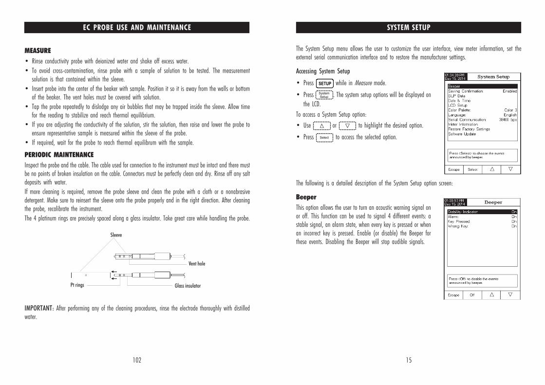
SYSTEM SETUP
The System Setup menu allows the user to customize the user interface, view meter information, set theexternal serial communication interface and to restore the manufacturer settings.
Accessing System Setup
• Press while in Measure mode.
• Press . The system setup options will be displayed on
the LCD.
To access a System Setup option:
• Use or to highlight the desired option.
• Press to access the selected option.
The following is a detailed description of the System Setup option screen:
Beeper
This option allows the user to turn an acoustic warning signal onor off. This function can be used to signal 4 different events: astable signal, an alarm state, when every key is pressed or whenan incorrect key is pressed. Enable (or disable) the Beeper forthese events. Disabling the Beeper will stop audible signals.
102
MEASURE
• Rinse conductivity probe with deionized water and shake off excess water.
• To avoid cross-contamination, rinse probe with a sample of solution to be tested. The measurementsolution is that contained within the sleeve.
• Insert probe into the center of the beaker with sample. Position it so it is away from the walls or bottomof the beaker. The vent holes must be covered with solution.
• Tap the probe repeatedly to dislodge any air bubbles that may be trapped inside the sleeve. Allow timefor the reading to stabilize and reach thermal equilibrium.
• If you are adjusting the conductivity of the solution, stir the solution, then raise and lower the probe toensure representative sample is measured within the sleeve of the probe.
• If required, wait for the probe to reach thermal equilibrum with the sample.
PERIODIC MAINTENANCE
Inspect the probe and the cable. The cable used for connection to the instrument must be intact and there mustbe no points of broken insulation on the cable. Connectors must be perfectly clean and dry. Rinse off any saltdeposits with water.
If more cleaning is required, remove the probe sleeve and clean the probe with a cloth or a nonabrasivedetergent. Make sure to reinsert the sleeve onto the probe properly and in the right direction. After cleaningthe probe, recalibrate the instrument.
The 4 platinum rings are precisely spaced along a glass insulator. Take great care while handling the probe.
IMPORTANT: After performing any of the cleaning procedures, rinse the electrode thoroughly with distilledwater.
EC PROBE USE AND MAINTENANCE
16
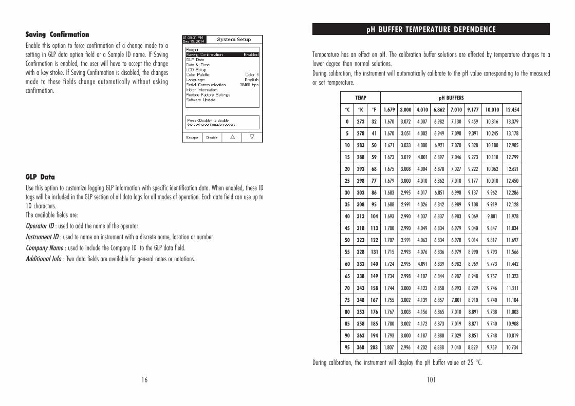
Saving Confirmation
Enable this option to force confirmation of a change made to asetting in GLP data option field or a Sample ID name. If SavingConfirmation is enabled, the user will have to accept the changewith a key stroke. If Saving Confirmation is disabled, the changesmade to these fields change automatically without askingconfirmation.
GLP Data
Use this option to customize logging GLP information with specific identification data. When enabled, these IDtags will be included in the GLP section of all data logs for all modes of operation. Each data field can use up to10 characters.The available fields are:
Operator ID : used to add the name of the operator
Instrument ID : used to name an instrument with a discrete name, location or number
Company Name : used to include the Company ID to the GLP data field.
Additional Info : Two data fields are available for general notes or notations.
101
pH BUFFER TEMPERATURE DEPENDENCE
Temperature has an effect on pH. The calibration buffer solutions are affected by temperature changes to alower degree than normal solutions.
During calibration, the instrument will automatically calibrate to the pH value corresponding to the measuredor set temperature.
During calibration, the instrument will display the pH buffer value at 25 °C.
PMET SREFFUBHp
C° K° F° 976.1 000.3 010.4 268.6 010.7 771.9 010.01 454.21
0 372 23 076.1 270.3 700.4 289.6 031.7 954.9 613.01 973.31
5 872 14 076.1 150.3 200.4 949.6 890.7 193.9 542.01 871.31
01 382 05 176.1 330.3 000.4 129.6 070.7 823.9 081.01 589.21
51 882 95 376.1 910.3 100.4 798.6 640.7 372.9 811.01 997.21
02 392 86 576.1 800.3 400.4 878.6 720.7 222.9 260.01 126.21
52 892 77 976.1 000.3 010.4 268.6 010.7 771.9 010.01 054.21
03 303 68 386.1 599.2 710.4 158.6 899.6 731.9 269.9 682.21
53 803 59 886.1 199.2 620.4 248.6 989.6 801.9 919.9 821.21
04 313 401 396.1 099.2 730.4 738.6 389.6 960.9 188.9 879.11
54 813 311 007.1 099.2 940.4 438.6 979.6 040.9 748.9 438.11
05 323 221 707.1 199.2 260.4 438.6 879.6 410.9 718.9 796.11
55 823 131 517.1 399.2 670.4 638.6 979.6 099.8 397.9 665.11
06 333 041 427.1 599.2 190.4 938.6 289.6 969.8 377.9 244.11
56 833 941 437.1 899.2 701.4 448.6 789.6 849.8 757.9 323.11
07 343 851 447.1 000.3 321.4 058.6 399.6 929.8 647.9 112.11
57 843 761 557.1 200.3 931.4 758.6 100.7 019.8 047.9 401.11
08 353 671 767.1 300.3 651.4 568.6 010.7 198.8 837.9 300.11
58 853 581 087.1 200.3 271.4 378.6 910.7 178.8 047.9 809.01
09 363 491 397.1 000.3 781.4 088.6 920.7 158.8 847.9 918.01
59 863 302 708.1 699.2 202.4 888.6 040.7 928.8 957.9 437.01

17
To add the GLP Data:
• Press while in Measure mode.
• Press .
• Use or to select the GLP Data option.
• Press and use or to highlight the
desired option.
• Press to edit the desired information. The Text Editor
menu will be displayed on the LCD.
• Enter the desired information by accepting the highlighted
character which is added to the text bar, using . The
and keys help the user to select the desired character. It is also possible to delete the last
character by positioning the cursor on the Backspace character ( ) and pressing .
• Press to return to the GLP Data options. If the Saving Confirmation is enabled, press to
accept the modified option, to escape without saving or to return to the editing mode.
Otherwise, the modified options are saved automatically.
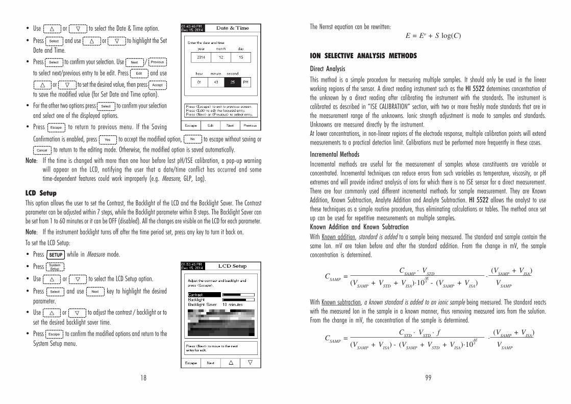
Date & Time
Set the current date & time and the format in which they appear.
Set Date and Time
This option allows you to set the current date (year/month/day) and time (hour/minute/second).
Notes: • Only years starting with 2000 are accepted.
• The time is set using the selected time format. For 12 Hour time format only, the AM/PM can
also be selected with or .
Set Time Format
Choose between 12 Hour (AM/PM) time format or 24 Hour time format.
Set Date Format
Choose the desired date format from 7 available options: DD/MM/YYYY, MM/DD/YYYY, YYYY/MM/DD, YYYY-MM-DD,Mon DD, YYYY, DD-Mon-YYYY or YYYY-Mon-DD.
To set the Date & Time:
• Press while in Measure mode.
• Press .
100
∆E - the difference of potential from the electrode;
S - the electrode slope, determined in a previouscalibration;
f - the stoichiometric ratio between sample and
standard;
where: CSAMP
- the sample concentration;
CSTD
- the standard concentration;
VSAMP
- the sample volume;
VSTD
- the standard volume;
VISA
- ISA volume
where: CSAMP
- the sample concentration;
CSTD
- the standard concentration;
VSAMP
- the sample volume;
VSTD
- the standard volume;
VISA
- ISA volume;
∆E - the difference of potential from the electrode;
S - the electrode slope, determined in a previouscalibration;
f - the stoichiometric ratio between sample and
standard;
Example 1
You have sulfide samples and you are adding Ag+. The reaction is:
One mole sulfide sample reacts with 2 moles silver standard (f = 1/2).
Example
You have sulfide samples and you are adding Pb2+. The reaction is:
One mole sulfide sample reacts with 1 mole lead standard (f = 1).
Analyte Addition and Analyte Subtraction
Analyte Addition and Subtraction are variations of the previous two methods.With Analyte Addition, sample (analyte) is added to an Ion standard being measured. The standard andsample contain the same ion. mV are taken before and after the sample addition. From the mV the analyteconcentration is determined.
With Analyte Subtraction, sample (analyte) is added to an Ion standard being measured. The analyte reactswith the measured Ion in a known manner thus removing measured ions from the solution. From the changein mV the concentration of the analyte is determined.
S2- + 2Ag+ → Ag2S
S2- + Pb2+ → PbS
CSAMP
= C
STD · V
STD ·
(VSTD
+ VSAMP
+ VISA
)·10∆E
- (VSTD
+ VISA
)
(VSTD
+ VISA
) VSAMP
S
CSAMP
= f ·(VSTD
+ VISA
) - [1 +
(VSTD
+ VISA
)]·10∆E ·(C
STD·V
STD )VSAMP
VSAMP
VSTD
+ VISA
S
18
• Use or to select the Date & Time option.
• Press and use or to highlight the Set
Date and Time.
• Press to confirm your selection. Use /
to select next/previous entry to be edit. Press and use
or to set the desired value, then press
to save the modified value (for Set Date and Time option).
• For the other two options press to confirm your selection
and select one of the displayed options.
• Press to return to previous menu. If the Saving
Confirmation is enabled, press to accept the modified option, to escape without saving or
to return to the editing mode. Otherwise, the modified option is saved automatically.
Note: If the time is changed with more than one hour before last pH/ISE calibration, a pop-up warningwill appear on the LCD, notifying the user that a date/time conflict has occurred and sometime-dependent features could work improperly (e.g. Measure, GLP, Log).
LCD Setup
This option allows the user to set the Contrast, the Backlight of the LCD and the Backlight Saver. The Contrastparameter can be adjusted within 7 steps, while the Backlight parameter within 8 steps. The Backlight Saver canbe set from 1 to 60 minutes or it can be OFF (disabled). All the changes are visible on the LCD for each parameter.
Note: If the instrument backlight turns off after the time period set, press any key to turn it back on.
To set the LCD Setup:
• Press while in Measure mode.
• Press .
• Use or to select the LCD Setup option.
• Press and use key to highlight the desired
parameter.
• Use or to adjust the contrast / backlight or to
set the desired backlight saver time.
• Press to confirm the modified options and return to the
System Setup menu.
99
The Nernst equation can be rewritten:
ION SELECTIVE ANALYSIS METHODS
Direct Analysis
This method is a simple procedure for measuring multiple samples. It should only be used in the linearworking regions of the sensor. A direct reading instrument such as the HI 5522 determines concentration ofthe unknown by a direct reading after calibrating the instrument with the standards. The instrument iscalibrated as described in “ISE CALIBRATION” section, with two or more freshly made standards that are inthe measurement range of the unknowns. Ionic strength adjustment is made to samples and standards.Unknowns are measured directly by the instrument.At lower concentrations, in non-linear regions of the electrode response, multiple calibration points will extendmeasurements to a practical detection limit. Calibrations must be performed more frequently in these cases.
Incremental Methods
Incremental methods are useful for the measurement of samples whose constituents are variable orconcentrated. Incremental techniques can reduce errors from such variables as temperature, viscosity, or pHextremes and will provide indirect analysis of ions for which there is no ISE sensor for a direct measurement.There are four commonly used different incremental methods for sample measurement. They are KnownAddition, Known Subtraction, Analyte Addition and Analyte Subtraction. HI 5522 allows the analyst to usethese techniques as a simple routine procedure, thus eliminating calculations or tables. The method once setup can be used for repetitive measurements on multiple samples.Known Addition and Known Subtraction
With Known addition, standard is added to a sample being measured. The standard and sample contain thesame Ion. mV are taken before and after the standard addition. From the change in mV, the sampleconcentration is determined.
With Known subtraction, a known standard is added to an ionic sample being measured. The standard reactswith the measured Ion in the sample in a known manner, thus removing measured ions from the solution.From the change in mV, the concentration of the sample is determined.
E = Eo + S log(C)
CSAMP
= CSTD
· VSTD
· f ·
(VSAMP
+ VISA
)
(VSAMP
+ VISA
) - (VSAMP
+ VSTD
+ VISA
)·10∆E
VSAMP
S
CSAMP
= CSAMP
· VSTD
· (V
SAMP + V
ISA)
(VSAMP
+ VSTD
+ VISA
)·10∆E
- (VSAMP
+ VISA
) VSAMP
S
19
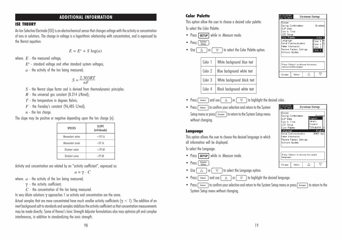
Color Palette
This option allow the user to choose a desired color palette.
To select the Color Palette:
• Press while in Measure mode.
• Press .
• Use or to select the Color Palette option.
• Press and use or to highlight the desired color.
• Press to confirm your selection and return to the System
Setup menu or press to return to the System Setup menu
without changing.
Language
This option allows the user to choose the desired language in whichall information will be displayed.
To select the Language:
• Press while in Measure mode.
• Press .
• Use or to select the Language option.
• Press and use or to highlight the desired language.
• Press to confirm your selection and return to the System Setup menu or press to return to the
System Setup menu without changing.
1roloC txeteulbdnuorgkcabetihW
2roloC txetetihwdnuorgkcabeulB
3roloC txetkcalbdnuorgkcabetihW
4roloC txetetihwdnuorgkcabkcalB
98
ISE THEORY
An Ion Selective Electrode (ISE) is an electrochemical sensor that changes voltage with the activity or concentrationof ions in solutions. The change in voltage is a logarithmic relationship with concentration, and is expressed bythe Nernst equation:
where: E - the measured voltage;
Eo - standard voltage and other standard system voltages;
a - the activity of the Ion being measured;
S - the Nernst slope factor and is derived from thermodynamic principles:R - the universal gas constant (8.314 J/Kmol);
T - the temperature in degrees Kelvin;
F - the Faraday’s constant (96,485 C/mol);
n - the Ion charge.
The slope may be positive or negative depending upon the Ion charge (n).
Activity and concentration are related by an “activity coefficient”, expressed as:
where: a - the activity of the Ion being measured;γ - the activity coefficient;C - the concentration of the Ion being measured.
In very dilute solutions γ approaches 1 so activity and concentration are the same.
Actual samples that are more concentrated have much smaller activity coefficients (γ < 1). The addition of aninert background salt to standards and samples stabilizes the activity coefficient so that concentration measurementsmay be made directly. Some of Hanna’s Ionic Strength Adjuster formulations also may optimize pH and complexinterferences, in addition to standardizing the ionic strength.
ADDITIONAL INFORMATION
SEICEPSEPOLS
)edaced/Vm(
noitactnelavonoM 61.95+
noinatnelavonoM 61.95–
noitactnelaviD 85.92+
noinatnelaviD 85.92–
E = Eo + S log(a)
S = 2.303RT
nF
a = γ · C
20
Serial Communication
This option allows the user to set the desired speed for the serial communication (baud rate) in bps. The meter andthe PC program must have the same baud rate.
To set the Serial Communication:
• Press while in Measure mode.
• Press .
• Use or to select the Serial Communication
option.
• Press and use or to highlight the
desired baud rate.
• Press to confirm your selection and return to the System
Setup menu or press to return to the System Setup menu
without changing.
Meter Information
This option provides general information about the instrument serial number (each instrument has a uniqueidentification serial number), the software version and the factory calibration date and time (for mV andtemperature).
Note: All instruments are factory calibrated for mV and temperature for Channel 1 and resistance and temperaturefor Channel 2. One year after factory calibration, a warning message starting “Factory CalibrationExpired” will be displayed when powering up the instrument. The instrument will still function, however,it should be taken to the nearest Hanna Customer Service for factory calibration.
To view the Meter Information:
• Press while in Measure mode.
• Press .
• Use or to select the Meter Information option.
• Press to acces the Meter Information menu.
• Press to return to the System Setup menu.
97
PC INTERFACE
Data transmission from the instrument to the PC can be done with the HI 92000 Windows® compatiblesoftware (optional). HI 92000 also offers graphing and on-line help features.
Data logged on the HI 5521 and HI 5522 meters can be exported to the most popular spreadsheetapplications for further analysis.
HI 5521 and HI 5522 instruments have an USB interface.
Use a standard USB cable to connect your instrument to the PC.
Make sure that the instrument and the HI 92000 software have the same baud rate and the appropriatecommunication port.
The PC software may also be used for real time logging.
To delete lots:
• Press while in Log Recall mode.
• Press or to access delete or delete all
mode. Otherwise, press to return to Log Recall view
mode.
• After selecting one of the Delete keys, use or
to select one lot and then press or
to delete the selected lot or all lots. The “Please wait...”message will be displayed on the LCD until the selected lotor all lots are deleted.
• Press and then press to exit deleting mode
and return to Log Recall view mode.
• Press to exit Log Recall mode and return to Measure mode.
Note: Logged lots should also be deleted whenever “Limited Automatic Logging Space” or “Automatic LogIs Full” message appears on the LCD, in the Reminder messages area.

21
• Press while in Measure mode to access channel
selection menu. Four available options will be displayed:Channel 1, Channel 2 or multi-channel with the first orthe second channel highlighted. The “Choose ChannelConfiguration” message is displayed in the Remindermessages area.
• Select the desired option by pressing the appropriate key:
, , or . The instrument will
display in the selected option Measure mode.
Restore Factory Settings
This option allows the user to erase all user settings and reset theinstrument to the default factory settings.
To restore the Factory Settings:
• Press while in Measure mode.
• Press .
• Use or to select the Restore Factory Settings
option.
• Press to confirm your selection. A pop-up menu will be
displayed, asking for confirmation.
• Press to confirm your selection and return to the System
Setup or press to return to the System Setup menu
without restoring defaults.
• Press to return to Measure mode.
Software update
This function allows the user to update instrument software. Inorder to start the PC upgrade application, you need to select theproper baud rate, the software update package and start theupdate.
CHANNEL SELECTION
96
• Press , or (HI 5522 only) to select
the desired Log Report type. All logged lots for the selectedLog Report type will be displayed on the LCD.
• To filter the displayed lots, press and then the
desired parameter. Only the selected measurement parameterlots will be displayed on the LCD.
• Select the desired lot with or and press
to display the logged data from the highlighted lot.
The “Please wait...” message will be displayed on the LCDfor one second. The selected Logging Data Configurationoptions will be displayed on the LCD, together with GLPinformation (last calibration date and calibrated buffers/standards) if a calibration has been performed on theselected mode and the logged values (measured value, mVvalue, temperature value, temperature compensation modeand the logging time).
Note: For automatic logging only, it is possible to view theplotted graph.
• Press to display the graph.
• By pressing it is possible to move the graph along
the X or Y axis with the arrow keys.
• If pressing while the graph is displayed, the zoom
menu for the X and Y axes will be accessed. Press ,
or / / / / /
/ / to switch between the active
zooming axes and then zoom in or out on the selected axis bypressing the appropriate virtual key.
• Press to return to the previous menu at any time.

22
pH SETUP
The pH Setup menu allows the user to set the parameters associated with pH measurement and calibration.
pH can be set for Channel 1 only.
Accessing pH Setup
• Press while in Measure mode and then to
select pH range for the desired channel.
• Press and then to access pH Setup menu.
To access a pH Setup option:
• Use or to highlight the desired option.
• Press to access the selected option.
The following is a detailed description of the pH Setup optionscreens.
Profile
This option opens the Profile manager. Enabling Profile allowsthe user to Save, Load or Delete an application Profile. The Profileoption allows the user to store up to ten separate profileapplications (five profiles for each channel). Each Profile can benamed and recalled at a moment’s notice. A profile is a sensorsetup complete with measurement units, logging and displaypreferences, calibration standards (Buffer or Standards includingcustom), setup of the Display screen for measurement (i.e. single,dual, graphing, GLP) and any other sensor configuration. Once saved,the exact same profile can be used at another time. This is ahandy feature if the meter is used occasionally for additionalapplications because it saves time in the setup of the meter andensures that the same procedure will be used.
To save the measurement configuration for pH mode:
• Press and use or to highlight Profile.
• Press / to enable / disable this feature.
95
3) Direct/AutoHold Reading Mode and Automatic Log
Press and then keys must be pressed on
front display to initiate this function. Real time continuousmeasurements are on display with “AutoHold” flashing andreal time continuous logging into meter memory, until the meterreaches the stability criteria to go into Auto Hold mode. Thestored sample logs will be marked with an “H” to indicate the
Auto Hold mode. The virtual key returns operation to
real time continuous measurements and stops the logging
session.
4) Direct/AutoHold Reading Mode and Manual Log
Press in order to add one new record in the log report. The manual log is working even if it is in
Auto Hold or Continuous reading mode. Press to initiate the Auto Hold event. “AutoHold” will
flash until the stability criteria is reached and then the screen freezes in Auto Hold mode, the data is markedwith an “H”.
5) Direct/AutoHold Reading Mode and Auto Hold Log
Press and then keys to initiate and automate the capture of stable data which is stored in
the Recall Manual Log file. During the process, “AutoHold” will flash until the stability criteria is reachedand then the screen freezes in Auto Hold mode, the data is logged and marked with an “H”. The virtual key
returns operation to Real time continuous measurement. Press again to log a second stable
data point. The lot ID along with the record index will appear for short time on the top/left corner on theselected channel window, every time a record will be added to the lot.
LOG RECALL
This feature allows the user to view all stored data. If no datawere logged, the “No records were found.” message will bedisplayed on the LCD in the Log Recall screen. Otherwise, theinstrument will display all the memorized lots in accordancewith the selected option: Automatic Log, Manual Log or ISEMethod Report (HI 5522 only) for Channel 1, or Automatic Log,Manual Log or USP Reports for Channel 2.
To view the memorized data:
• Press while in Measure mode.
• Press . Choose channel and then select the log report type.

23
The available options are:
Save Profile: save the current profile.
Save Profile As...: save current profile using a specific name.
Load Profile: load from available profiles.
Delete Profile: delete a profile.
Save Current Profile
To save the current profile:
• Use or to select Save Profile or Save Profile As...
• Press . The Text Editor box will be displayed on the LCD.
• Enter the desired profile name by using and to highlight the desired character and then press
to add it to the text bar. It is also possible to delete the last character by positioning the cursor on the
Backspace character ( ) and pressing .
• Press to return to the Profile options.
• Use Save Profile to save changes made to a presently used Profile. Changes will overwrite existing configurations.
• Select Load Profile to select a profile to use from the list of saved profiles. Highlight the desired profile and
press .
• Select Delete Profile to remove a selected profile from the saved list.
Highlight the profile and press .
Temperature
The temperature has a direct influence on pH. This option allows the user to choose the temperature source andunits, as well as the desired manual temperature for manual temperature compensation mode.
Temperature Source
If using a temperature probe, Automatic Temperature Compensation will be performed relative to the displayedtemperature, with the “ATC” indicator displayed on the LCD. A single temperature probe can be used for bothmeasurement channels if desired. Select the source by selecting Manual, Channel 1 or Channel 2. If no temperatureprobe is detected, Manual Temperature Compensation will be performed, with the “MTC” indicator on the LCD.
Temperature Unit
The desired temperature unit can be chosen (Celsius, Fahrenheit or Kelvin degrees) and the meter will automaticallymake the conversion for the selected unit.
Manual Temperature
If no temperature probe is connected, the desired temperature can be set manually. The default setting is 25 °C.If the measured temperature is different, the value can be manually adjusted to obtain an accurate pH measurement.
94
LOGGING
edoMgnidaeR goL llaceRgol
)1(citamotuA goLcitamotuA
tceriD )2(launaM goLlaunaM
)AN(dloHotuA elbacilppAtoN
)3(citamotuA goLcitamotuA
dloHotuA/tceriD )4(launaM goLlaunaM
)5(dloHotuA goLlaunaM
There are 5 ways the Reading Mode and Log may be configured together. The table below shows thecombinations and indicates where the completed log will be stored.
2) Direct Reading Mode and Manual Log:
Real time continuous measurements are on display and snapshotsof measurement data are stored in the Manual log when the user
presses . Subsequent snapshots will be added to the
same Manual Lot every time the is depressed unless
New Lot is selected under Log options.
Note: When the is pressed the lot ID along with the
current record number will appear for short time on theselected channel window on the top/left corner (e.g.L033_MV 8 - this means lot ID L033_mV and recodnumber 8).
1) Direct Reading Mode and Automatic Log:
Real time continuous measurements are on display and continuouslogs to meter memory. These are sometimes referred as interval
logs. Press .
24
To set one of the Temperature options:
• Press while in pH Measure mode.
• Press .
• Use or to select the Temperature option.
• Press and use or to highlight the
desired Temperature option you wish to modify.
• Press and use or to highlight the
desired option (for Temperature Source & Unit options) or use
or to adjust the temperature value between
the displayed limits (for Manual Temperature option).
• Press to confirm your selection (for Temperature Source
& Unit options) or press to save the current value (for Manual Temperature option). Otherwise, press
to cancel operation.
CalibrationThis option allows the user to setup desired parameters related to the calibration.
Buffer Entry TypeThree settings are available for the pH buffers used for electrode calibration:Automatic - the instrument automatically selects the closest buffer to the measured pH value from thepredefined buffers chosen in the option Edit Buffer Group.Semiautomatic - the instrument automatically selects the closest buffers to the measured pH value from allavailable buffers and you can choose the one used, from standard and custom buffers.Manual Selection - the desired pH buffer is manually selected from all available buffers (standard andcustom).
To set the Buffer Entry Type:
• Press while in pH Measure mode.
• Press .
• Use or to select the Calibration option.
• Press and use or to highlight the
Buffer Entry Type option.
• Press and use or to highlight the
desired option.
• Press to confirm your selection or press to
cancel operation.
93
The user temperature calibration menu can be accessed during meter startup by simultaneously pressingthree keys as shown in the drawing below. Press the keys after the short beep is heard at the meter poweron. Keep all three keys pressed until Temp. Calibration menu appear.
Note: The user temperature calibration is performed at three points: around 0 °C, 50 °C and 100 °C.
To perform the user temperature calibration:
• Select the desired temperature channel by pressing
(the temperature channel is switched between temperature ECchannel and temperature pH channel).
• Press to start the temperature calibration. Adjust the
temperature preset value using or when
necessary.
• Insert the EC probe into the beaker with water at 0 °C.
• Wait for measurement to stabilize and then press to
confirm the calibration point.
• Repeat the previous steps for 50 °C and 100 °C.
• Save the calibration.
• Press to return to measure mode.
Note: Press if you want to clear the temperature user calibration.
TEMPERATURE CALIBRATION
a0=0.008 b
0=0.0005 A
1=2.070·10-5 c
0=6.766097·10-1
a1=-0.1692 b
1=-0.0056 A
2=-6.370·10-10 c
1=2.00564·10-2
a2=25.3851 b
2=-0.0066 A
3=3.989·10-15 c
2=1.104259·10-4
a3=14.0941 b
3=-0.0375 B
1=3.426·10-2 c
3=-6.9698·10-7
a4=-7.0261 b
4=0.0636 B
2=4.464·10-4 c
4=1.0031·10-9
a5=2.7081 b
5=-0.0144 B
3=4.215·10-1
B4=-3.107·10-3
25
1st Cal. PointTwo options are available for the 1st Cal. Point parameter: Point andOffset.
Point: A new buffer can be added to an existing calibration. Theelectrode slope will be reevaluated with the addition of this buffer(normal operation).
Offset: The new buffer calibration point can create a constantoffset to all existing pH calibration data (existing calibrationmust have a minimum of two pH buffers).
To set the 1st Cal. Point:
• Press while in pH Measure mode.
• Press .
• Use or to select the Calibration option.
• Press and use or to highlight the 1st Cal. Point option.
• Press / as desired.
• Press to return to previous menu.
Edit Custom Buffers
If special custom pH buffers are required during calibration, theEdit Custom Buffers option is available. Up to five pH custombuffers can be added. If a custom buffer is used, the user mustverify it’s value at the temperature of calibration.
To edit/set the Custom Buffers:
• Press while in pH Measure mode.
• Press .
• Use or to select the Calibration option.
• Press and use or to highlight the Edit
Custom Buffers option.
• For a previous set value, press to set the custom buffer value to “----” if desired and confirm the
setting by pressing , otherwise press to edit the selected custom buffer.
• While in edit custom buffer menu press to set the custom buffer value to 7.000 pH and then use
or to set the desired custom buffer value.
92
S = - 0.08996 + 28.2929729R15
+ 12.80832R15
2 - 10.67869R15
3 + 5.98624R15
4 - 1.32311R15
5
Note: The formula can be applied for temperatures between 10 °C and 31 °C.
PRACTICAL SALINITY SCALE (UNESCO 1978)
The PSU scale extends from 0-42. The Practical salinity (S) of seawater relates the ratio of electricalconductivity of a normal seawater sample at 15 °C and 1 atmosphere to a potassium chloride solution(KCl) with a mass of 32.4356 g/kg water at the same temperature and pressure. Under these conditionsthe ratio is equal to 1 and S=35. The Practical salinity scale may be applied to values 2 through 42 PSUat temperature between -2 °C to 35 °C.
S is defined in terms of the ratio K15
.
S = 0.0080-0.1692K15
1/2+25.3851K15
+14.0941K15
3/2-7.0261K15
2+2.7081K15
5/2
Where C is Conductivity;
C(35,15,0)=0.042933 S/cm
The simplified equation above is derived from
With the following coefficients and k = 0.0162 and
Seawater temperature coefficient rT = c
0 + c
1·T + c
2·T2 + c
3·T3 + c
4·T4
S = a0 + a
1·R
T
1/2 + a2·R
T + a
3·R
T
3/2 + a4·R
T
2 + a5·R
T
5/2 + (T - 15)
·
[b0 + b
1·R
T
1/2 + b2·R
T + b
3·R
T
3/2 + b4·R
T
2 + b5·R
T
5/2]
1 + k(T-15)
R = C
(S,T,P)
= (R
P·R
T·r
T)
C(35,15,10)
K15
= C(S,15,0)
C(KCl,15,0)
Three methods for calculating seawater salinity are supported (Natural Sea Water Scale, Practical SalinityScale and Percent Scale).
PERCENT SCALE (1902)
This salinity scale extends from 0 to 400%. The formula followed is:
S%
= 1.805Cl + 0.03
where salinity is defined as the total amount of solid materials in grams dissolved in one kilogram ofseawater. 100% Salinity has ~10% solids and is considered normal seawater.
NATURAL SEA WATER SCALE (UNESCO 1966)
The Natural Sea Water Scale extends from 0 - 80.0 ppt. It determines salinity based upon a conductivityratio of sample to “standard seawater” at 15 °C.
SALINITY MEASUREMENT
C(35,15)·rT
R15
= C
T(sample)
RT=
RR
P·r
T
RP=1+
P·(A1 + A
2·P + A
3·P2)
1+B1·T + B
2·T2 + B
3·R + B
4·R·T
;
where R15
is the conductivity ratio, and Salinity is defined by the following equation.
26
• Press to exit custom buffer edit menu. If the Saving Confirmation is enabled, press to accept
the modified option, to escape without saving or to return to the editing mode. Otherwise,
the modified option is saved automatically.
• Use key to select the next custom buffer to be set or press to return to Calibration options.
Edit Buffer Group
Accessing this option, the user can edit the desired group of five pHbuffers for automatic buffer recognition (Automatic Buffer EntryType). If the Buffer Group already contains five pH buffers, at leastone pH buffer has to be removed in order to add another buffer.
To edit/set the Buffer Group:
• Press while in pH Measure mode.
• Press .
• Use or to select the Calibration option.
• Press and use or to highlight the Edit
Buffer Group option.
• Press and use and to choose the pH buffer to be included in the buffer group.
• Press or to add/remove the selected pH buffer to/from the buffer group.
• Press to return to Calibration options and to save the changes.
Calibration Reminder
This option allows the user to select a calibration reminderschedule. Three options are available for the calibration reminder:Daily, Periodic or Disabled.
To set the Calibration Reminder:
• Press while in pH Measure mode.
• Press .
• Use or to select the Calibration option.
• Press and use or to highlight the
Calibration Reminder option.
• Press and use or to highlight the desired option.
• Press to confirm your selection or press to cancel operation.
91
SALINITY CALIBRATION
Note: Salinity calibration is made in conductivity mode when using Natural Sea Water or Practical SeaWater measurement. Direct salinity calibration is only possible when using the older percent scale.
Salinity calibration is a single-point calibration procedure at 100.0%. Use the HI 7037L calibrationsolution (salinity solution) as a 100% seawater solution.
To enter salinity calibration:
• Set the meter for salinity range.• Select the Percent Scale (see Salinity Setup section).• Rinse the probe with some of the calibration solution or deionized water.• Immerse the probe in HI 7037L solution. The sleeve holes must be completely submerged. Tap the
probe repeatedly to remove any air bubbles that may be trapped inside the sleeve. Position probe awayfrom the wall or bottom of the container.
• Enter in calibration mode by pressing .
• Wait for measurement to stabilize.
• Press to finish salinity calibration or press to cancel calibration.
CALIBRATION MESSAGES
• Wrong standard solution. Check the standard solution. This message appears when the differencebetween the reading and the value of the selected standard is significant. If this message is displayed,check if you have selected the appropriate calibration standard.
• Wrong standard temperature. This message appears if the standard temperature is out of theallowable standard temperature range (0 - 60 °C).
• Press <Clear Cal> to clear old calibration.: Clear the old calibration.
27
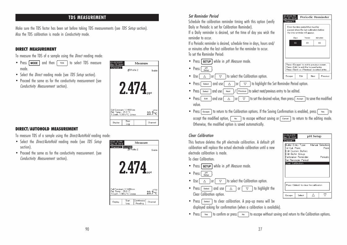
Set Reminder PeriodSchedule the calibration reminder timing with this option (verifyDaily or Periodic is set for Calibration Reminder).If a Daily reminder is desired, set the time of day you wish thereminder to occur.If a Periodic reminder is desired, schedule time in days, hours and/or minutes after the last calibration for the reminder to occur.To set the Reminder Period:
• Press while in pH Measure mode.
• Press .
• Use or to select the Calibration option.
• Press and use or to highlight the Set Reminder Period option.
• Press and use / to select next/previous entry to be edited.
• Press and use or to set the desired value, then press to save the modified
value.
• Press to return to the Calibration options. If the Saving Confirmation is enabled, press to
accept the modified option, to escape without saving or to return to the editing mode.
Otherwise, the modified option is saved automatically.
Clear Calibration
This feature deletes the pH electrode calibration. A default pHcalibration will replace the actual electrode calibration until a newelectrode calibration is made.
To clear Calibration:
• Press while in pH Measure mode.
• Press .
• Use or to select the Calibration option.
• Press and use or to highlight the
Clear Calibration option.
• Press to clear calibration. A pop-up menu will be
displayed asking for confirmation (when a calibration is available).
• Press to confirm or press to escape without saving and return to the Calibration options.
90
Make sure the TDS factor has been set before taking TDS measurements (see TDS Setup section).
Also the TDS calibration is made in Conductivity mode.
DIRECT MEASUREMENT
To measure the TDS of a sample using the Direct reading mode:
• Press and then to select TDS measure
mode.
• Select the Direct reading mode (see TDS Setup section).
• Proceed the same as for the conductivity measurement (seeConductivity Measurement section).
DIRECT/AUTOHOLD MEASUREMENT
To measure TDS of a sample using the Direct/AutoHold reading mode:
• Select the Direct/AutoHold reading mode (see TDS Setupsection).
• Proceed the same as for the conductivity measurement. (seeConductivity Measurement section).
TDS MEASUREMENT

28
Sample ID
This option allows the user to assign an identification number/name. Two Sample ID options are available: ID Increment and EditSample ID.
ID Increment
Two choices are available for the sample ID:
None - the sample ID will be fixed and it can be enteredalphanumerically (see Edit Sample ID).
Automatic - the sample ID will automatically increment by onefor each new log lot.
To set the ID Increment mode:
• Press while in pH Measure mode.
• Press .
• Use or to select the Sample ID option.
• Press and use or to highlight the ID Increment option.
• Press / as desired.
• Press to return to previous menu.
Edit Sample ID
This option allows the user to edit the sample ID.
Note: The ID Increment mode must be set to None, to use thisfeature.
To edit the Sample ID:
• Press while in pH Measure mode.
• Press .
• Use or to select the Sample ID option.
• Press and use or to highlight the Edit
Sample ID option.
• Press to confirm your selection.
• If the selected increment is None, the Text Editor menu will be displayed on the LCD, allowing you to enter thedesired sample number/name by accepting the highlighted character which is added in the text bar, using
. The and keys help the user to select the desired character.
89
Make sure the instrument and probe has been calibrated in conductivity mode before taking resistivitymeasurements.
DIRECT MEASUREMENT
To measure the resistivity of a sample using the Direct readingmode:
• Press and then to select resistivity measure
mode.
• Select the Direct reading mode (see Resistivity Setup section).
• Proceed the same as for the conductivity measurement (seeConductivity Measurement section).
DIRECT/AUTOHOLD MEASUREMENT
To measure resistivity of a sample using the Direct/AutoHoldreading mode:
• Select the Direct/AutoHold reading mode (see ResistivitySetup section).
• Proceed the same as for the conductivity measurement. (seeConductivity Measurement section).
RESISTIVITY MEASUREMENT

29
It is also possible to delete the last character; position the cursor on the Backspace character and press
.
• Press to return to Sample ID options. If the Saving
Confirmation is enabled, press to accept the modified
option, to escape without saving or to return to
the editing mode. Otherwise, the modified options are savedautomatically.
• If the selected increment mode is Automatic, the desired sample
ID value can be set using or .
• Press to save the current value or press to
cancel operation.
Stability Criteria
This option allows the user to select the signal stability criterion for the measured parameter (pH, mV, ISE):
Fast - this setting will give faster results with less accuracy.
Medium - this setting will give medium speed results with medium accuracy.
Accurate - this setting will give slower results with high accuracy.
To set the Stability Criteria:
• Press while in pH Measure mode.
• Press .
• Use or to select the Stability Criteria option.
• Press and use or to highlight the
desired option.
• Press to confirm your selection or press to
cancel operation.
Reading Mode
This option allows the user to select between Direct and Direct/AutoHold pH mode.
Direct - the current reading is displayed in realtime on the LCD.
Direct/AutoHold - the current reading can be frozen on the LCD when is pressed and the stability criterion is reached.
88
Stage 3 - this is an off-line test that studies the pH and CO2.
If the water sample has failed Stage 1 and Stage 2 tests, Stage 3 testing must be conducted.
To perform this test use Channel 1 in pH mode. Have acalibrated pH sensor installed.
Note: A temperature bath at 25.0 ±1 °C is required for thismeasurement.
• Take the water sample from the stage 2 test and increase itsionic strength for a pH measurement at 25 °C.
• Use 100 mL of Stage 2 water and add 300 µL saturated KCl tothe sample.
• Calibrate a pH sensor in pH 4.01 and pH 6.862 (or 7.01)buffers.
• Thermally equilibrate the sample to 25.0 ±1 °C.
• Measure sample with the calibrated pH sensor.
• The pH of sample must be between 5.0 and 7.0 pH.
• Record the pH and round it to the nearest 0.1 pH.
• Find the measured pH and corresponding conductivity in the stage 3 table below.
• Compare the conductivity value determined in stage 2 to the conductivity value found in the stage 3 table.
• If the stage 2 conductivity is lower than the conductivity from the table below, the sample has meet theUSP requirements. Otherwise, the water didn’t meet the USP requirements.
Note: If the Stage 2 water fails, the meter automatically changes to pH and starts Stage 3 evaluation.Having 25 °C sample with added ionic salt is required. At the conclusion at Stage 3 evaluation, press
to store a report of the results. The report may be printed using HI 92000 software.
HpytivitcudnoC
( mc/Sµ )Hp
ytivitcudnoC)mc/Sµ(
HpytivitcudnoC
)mc/Sµ(
0.5 7.4 7.5 5.2 4.6 3.2
1.5 1.4 8.5 4.2 5.6 2.2
2.5 6.3 9.5 4.2 6.6 1.2
3.5 3.3 0.6 4.2 7.6 6.2
4.5 0.3 1.6 4.2 8.6 1.3
5.5 8.2 2.6 5.2 9.6 8.3
6.5 6.2 3.6 4.2

30
To set the Reading Mode:
• Press while in pH Measure mode.
• Press .
• Use or to select the Reading Mode option.
• Press / to select Direct / AutoHold option as
desired.
• Press to cancel operation.
Log
Note: See Logging section for available types of logging.
This option allows the user to edit the log settings: Logging Type, Logging Data Configuration, Sampling Periodand New Lot.
Logging Type
Three logging types are available: Automatic, Manual and Auto Hold.
Automatic - the measurement data is logged automatically at constant time intervals;
Manual - a snapshot of the displayed measurement data is logged with time stamp when the user manuallydepresses Log;
Auto Hold - this is configured along with the Direct/AutoHold Reading Mode to take a snapshot of stable
measurement data. Press to initiate a logging session. Press to initiate an Auto Hold event. The
log occurs automatically once measurement stability is reached. This type log removes subjective data, as it onlycaptures stable measurements.
To set the Logging Type:
• Press while in pH Measure mode.
• Press .
• Use or to select the Log option.
• Press and use or to highlight the
Logging Type option.
• Press and use or to highlight the
desired option.
• Press to confirm your selection or press to
cancel operation.
87
• At the conclusion of the test period the results will be displayed.
• The user may View the results as a report. Press .
• A copy of the sample results may also be saved. Press .
This may be printed using HI 92000 software.
Stage 2 - this is an off-line test.
To perform this test:
• Store the water sample in an enclosed clean container thathas been rinsed previously with water of the same quality.
• Adjust the sample’s temperature to 25 °C and agitate thesample to ensure that it has equilibrated with ambient CO
2.
• If the measured conductivity is less than 2.1 µS/cm, then thesample has met the USP requirements.
• Otherwise, proceed to Stage 3 testing.
Stage 2 steps:
Note: A temperature bath at 25.0 ±1 °C is required for thismeasurement.
• Press from the keypad.
• An instruction prompt will pop up with instructions for samplepreparation.
• Using measurement technique outlined in direct measurement,place probe into sample.
• Press .
• The meter will begin to evaluate stability of the conductivitymeasurement. At the conclusion of the test period the resultswill be displayed. If the sample has passed the evaluationthe testing is finished and the water may be used.
• Press to store a copy of the sample results. This may
be printed using HI 92000 software.
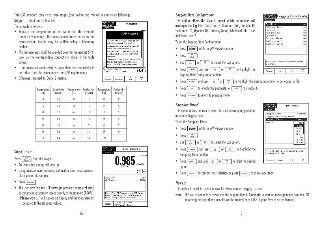
31
Logging Data Configuration
This option allows the user to select which parameters willaccompany a log File: Date/Time, Calibration Data, Sample ID,Instrument ID, Operator ID, Company Name, Additional Info 1 andAdditional Info 2.
To set the Logging Data Configuration:
• Press while in pH Measure mode.
• Press .
• Use or to select the Log option.
• Press and use or to highlight the
Logging Data Configuration option.
• Press and use or to highlight the desired parameter to be logged in file.
• Press to enable the parameter or to disable it.
• Press to return to previous menu.
Sampling Period
This option allows the user to select the desired sampling period forautomatic logging type.
To set the Sampling Period:
• Press while in pH Measure mode.
• Press .
• Use or to select the Log option.
• Press and use or to highlight the
Sampling Period option.
• Press and use or to select the desired
option.
• Press to confirm your selection or press to cancel operation.
New Lot
This option is used to create a new lot when manual logging is used.
Note: If New Lot option is accessed and the Logging Type is Automatic, a warning message appears on the LCDinforming the user that a new lot can be created only if the Logging Type is set as Manual.
86
erutarepmeT)C°(
ytivitcudnoC( mc/Sµ )
erutarepmeT)C°(
ytivitcudnoC)mc/Sµ(
erutarepmeT)C°(
ytivitcudnoC)mc/Sµ(
0 6.0 53 5.1 07 5.2
5 8.0 04 7.1 57 7.2
01 9.0 54 8.1 08 7.2
51 0.1 05 9.1 58 7.2
02 1.1 55 1.2 09 7.2
52 3.1 06 2.2 59 9.2
03 4.1 56 4.2 001 1.3
This USP standard consists of three stages (one in-line and two off-line tests) as followings:
Stage 1 - this is an in-line test.
The procedure follows:
• Measure the temperature of the water and the absoluteconductivity readings. The measurement must be on in-linemeasurement. Results may be verified using a laboratorymethod.
• The temperature should be rounded down to the nearest 5 °C.Look up the corresponding conductivity value in the tablebelow.
• If the measured conductivity is lower than the conductivity inthe table, then the water meets the USP requirements.
• Otherwise, proceed to Stage 2 testing.
Stage 1 steps:
Press from the keypad.
• An instruction prompt will pop up.
• Using measurement technique outlined in direct measurement,place probe into sample.
• Press .
• The user may Edit the USP factor (to provide a margin of error)or compare measurement results directly to the standard (100%).“Please wait ...” will appear on display and the measurementis compared to the standard values.

32
To generate a New Lot:
• Press while in pH Measure mode.
• Press .
• Use or to select the Log option.
• Press and use or to highlight the New
Lot option.
• Press to generate a new manual lot. A pop-up menu will
be displayed asking for confirmation.
• Press to confirm or press to escape without
saving and return to the Log options.
Alarm
This option allows the user to select the alarm settings: Alarm State and Alarm Limits. If the Alarm optionis enabled, a continuous double beep will be heard, along with the “Alarm” indicator blinking on the LCD,each time the set limits in Measure mode are exceeded.Note: Alarm Beeper must be set On for audible beep to be heard.
See: System Setup > Beeper > Alarm.
Alarm StateThree settings are available for the Alarm State option:Disabled - the alarm will be disabled.Inside Limits - the alarm state will trigger when the measured value is inside the set limits.
Outside Limits - the alarm state will trigger when the measured value is outside the set limits.To set the Alarm State:
• Press while in pH Measure mode.
• Press .
• Use or to select the Alarm option.
• Press and use or to highlight the Alarm
State option.
• Press and use or to highlight the
desired option.
• Press to confirm your selection or press to cancel
operation.Alarm LimitsThis option allows the user to set the alarm limits for the measured value.Note: The Alarm High value can not be lower than the Alarm Low value.
85
DIRECT/AUTOHOLD MEASUREMENT
To measure conductivity of a sample using the Direct/AutoHoldreading mode:• Follow sample and probe directions found under Direct
Measurement.• Select the Direct/AutoHold reading mode (see Conductivity
Setup).
• If pressing , the “AutoHold” indicator will start
blinking on the display until the stability criterion is reached.The conductivity value will be frozen on the display, alongwith “AutoHold” indicator.
• To return to normal measure mode press .
The United States Pharmacopoeia Regulations establishes limitsand calibration requirements for WFI (Water For Injection). TheHI 5521 and HI 5522 meters contains both conductivity and pHmeasurements that are needed for off line measurements in a Stage2 and 3 of the regulation. Stage 1 verification may be carried out ina container but the regulation requires an in-line measurement. Themeter provides prompts and instructions to make the measurementseasily. Calibrate a pH sensor on Channel 1 and EC probe on Channel 2 priorto storing USP analysis.
To access the USP menu:
• Highlight Channel 2 and select from the basic
display to select .
• Press then .
• Select the Direct/USP reading mode (see Conductivity Setup).
• Return to measure mode by pressing .
• Verify conductivity probe has been calibrated in conductivitystandards in the lowest measurement range.
• Press and then select the desired USP stage.
In this measure mode the user can check for water quality usingthe United States Pharmacopeia standard (USP <645>) guidelinesfor water for injection.
USP EVALUATION

33
To set the Alarm Limits:
• Press while in pH Measure mode.
• Press .
• Use or to select the Alarm option.
• Press and use or to highlight the
Alarm Limits option.
• Press and use / to select next/
previous entry to be edited.
• Press and use or to set the desired
value, then press to save the modified value.
• Press to return to the Alarm options. The modified option is saved automatically.
Isopotential Point
This option allows the user to edit the isopotential point of the electrode used for pH measurements. Theisopotential point is the mV reading for an electrode at which temperature has no effect on the measurement. Theideal electrode has an isopotential point of 0.0 mV and 7.00 pH, while an actual electrode typically deviatesslightly from the ideal values.
If the actual isopotential pH for an electrode is known, it can be set by accessing this option.
Note: If the isopotential point has been modified, recalibration must be performed.
To set the Isopotential Point:
• Press while in pH Measure mode.
• Press .
• Use or to select the Isopotential Point option.
• Press and set the desired isopotential pH value using
or .
• Press to save the current value or press to
cancel operation.
84
CALIBRATION MESSAGES
• Wrong standard solution. Check the standard solution. This message appears when the differencebetween the reading and the value of the selected standard is significant. If this message is displayed,check if you have selected the appropriate calibration standard.
• Wrong standard temperature. This message appears if the standard temperature is out of theallowable standard temperature range (0 - 60 °C).
• The current range was already calibrated. Change the standard solution. The calibration for thisconductivity range was already done. Please change the standard.
• Press <Clear Offset> to clear old calibration. Clear the offset of the electrode calibration.
• Press <Clear Cal> to clear old calibration. Clear all old calibrated standards.
CONDUCTIVITY MEASUREMENT
Make sure the instrument has been calibrated before taking conductivity measurements.
DIRECT MEASUREMENT
To measure the conductivity of a sample using the Direct reading mode:
• Highlight Channel 2 and press and then to
select conductivity measure mode.
• Select the Direct reading mode (see Conductivity Setup).
• The conductivity probe should be rinsed with deionized water.
• Shake off excess water.
• If possible rinse probe with a sample of solution to be tested.Swirl and raise and lower probe in this rinse solution.
• Insert probe in center of a beaker with the sample, awayfrom the wall or bottom of beaker. The upper vent holes mustbe covered with solution.
• Gently stir solution and wait for probe to reach thermalequilibrium with the sample.
• Tap probe repeatedly to dislodge any air bubbles that may be trapped inside the sleeve. Allow time forthe reading to stabilize.
• The measured conductivity value will be displayed on the Channel 2 screen.
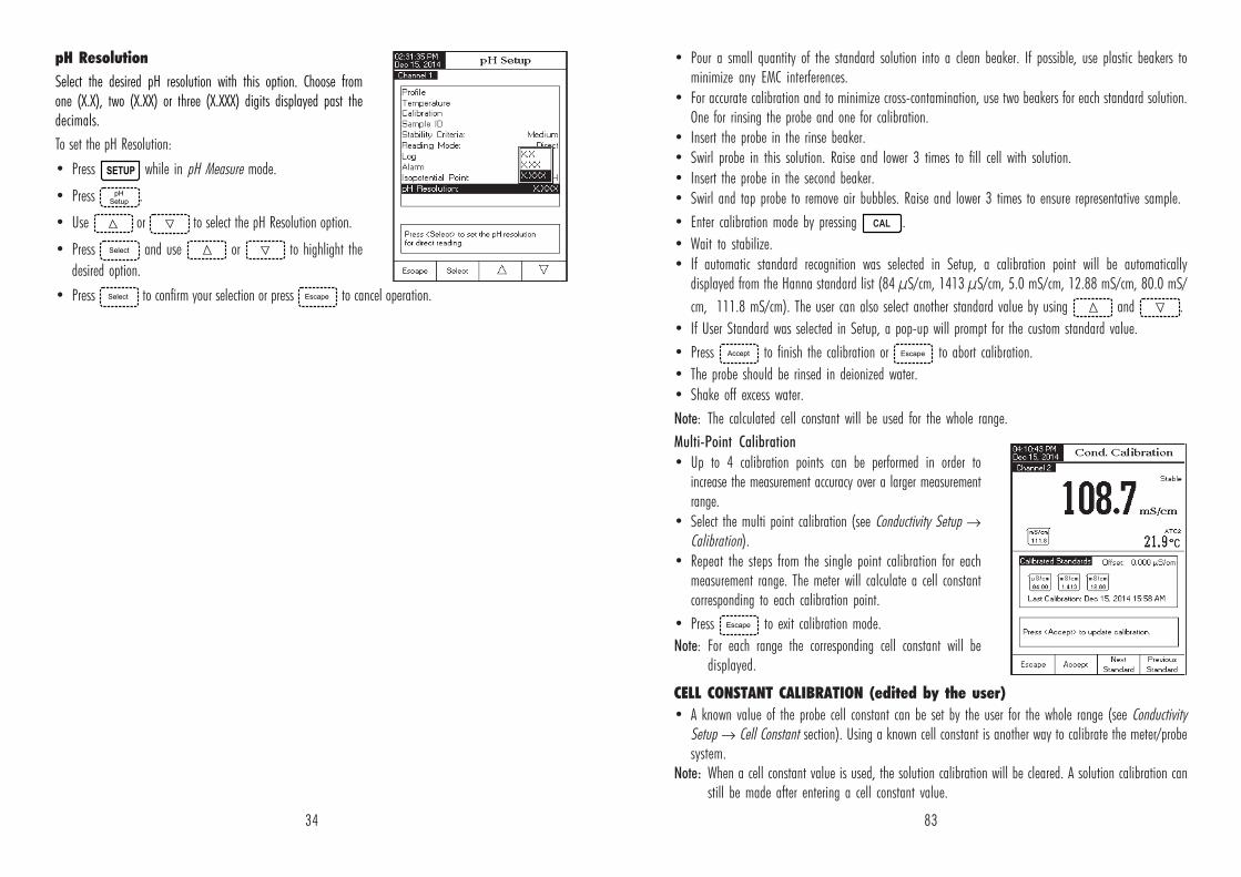
34
pH Resolution
Select the desired pH resolution with this option. Choose fromone (X.X), two (X.XX) or three (X.XXX) digits displayed past thedecimals.
To set the pH Resolution:
• Press while in pH Measure mode.
• Press .
• Use or to select the pH Resolution option.
• Press and use or to highlight the
desired option.
• Press to confirm your selection or press to cancel operation.
83
• Pour a small quantity of the standard solution into a clean beaker. If possible, use plastic beakers tominimize any EMC interferences.
• For accurate calibration and to minimize cross-contamination, use two beakers for each standard solution.One for rinsing the probe and one for calibration.
• Insert the probe in the rinse beaker.• Swirl probe in this solution. Raise and lower 3 times to fill cell with solution.
• Insert the probe in the second beaker.• Swirl and tap probe to remove air bubbles. Raise and lower 3 times to ensure representative sample.
• Enter calibration mode by pressing .
• Wait to stabilize.• If automatic standard recognition was selected in Setup, a calibration point will be automatically
displayed from the Hanna standard list (84 µS/cm, 1413 µS/cm, 5.0 mS/cm, 12.88 mS/cm, 80.0 mS/
cm, 111.8 mS/cm). The user can also select another standard value by using and .
• If User Standard was selected in Setup, a pop-up will prompt for the custom standard value.
• Press to finish the calibration or to abort calibration.
• The probe should be rinsed in deionized water.
• Shake off excess water.
Note: The calculated cell constant will be used for the whole range.
Multi-Point Calibration
• Up to 4 calibration points can be performed in order toincrease the measurement accuracy over a larger measurementrange.
• Select the multi point calibration (see Conductivity Setup →Calibration).
• Repeat the steps from the single point calibration for eachmeasurement range. The meter will calculate a cell constantcorresponding to each calibration point.
• Press to exit calibration mode.
Note: For each range the corresponding cell constant will bedisplayed.
CELL CONSTANT CALIBRATION (edited by the user)
• A known value of the probe cell constant can be set by the user for the whole range (see ConductivitySetup → Cell Constant section). Using a known cell constant is another way to calibrate the meter/probesystem.
Note: When a cell constant value is used, the solution calibration will be cleared. A solution calibration canstill be made after entering a cell constant value.
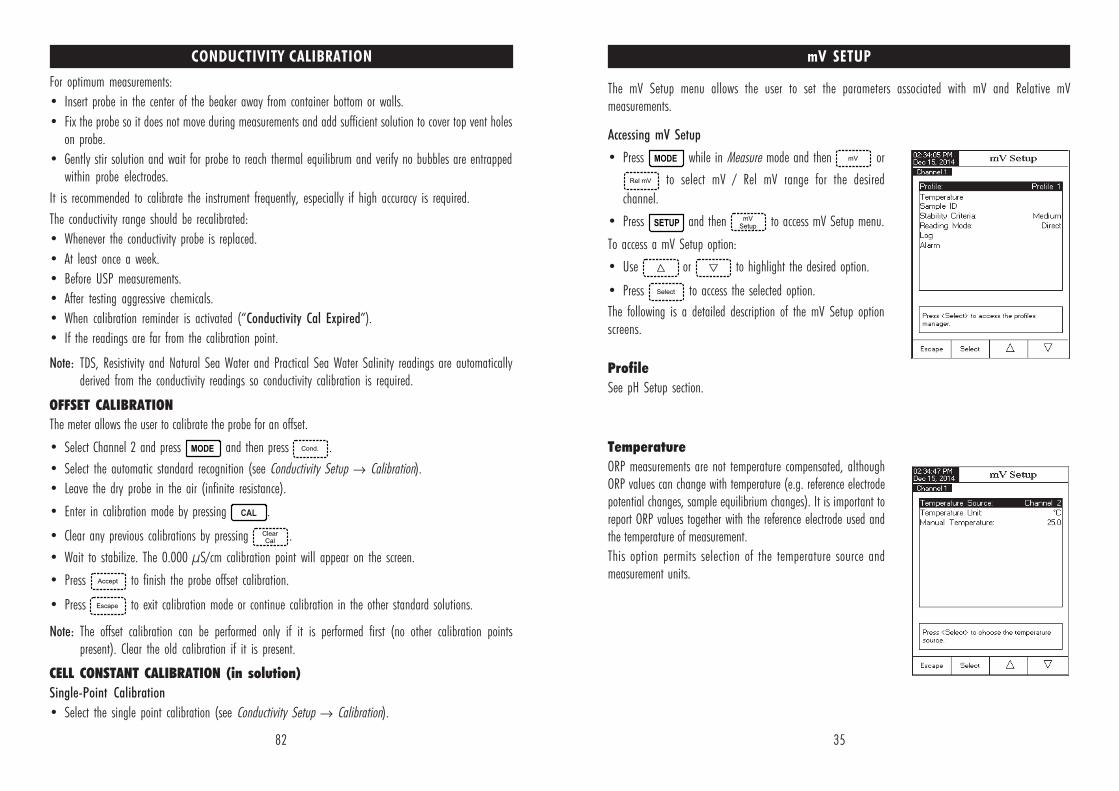
35
mV SETUP
The mV Setup menu allows the user to set the parameters associated with mV and Relative mVmeasurements.
Accessing mV Setup
• Press while in Measure mode and then or
to select mV / Rel mV range for the desired
channel.
• Press and then to access mV Setup menu.
To access a mV Setup option:
• Use or to highlight the desired option.
• Press to access the selected option.
The following is a detailed description of the mV Setup optionscreens.
Profile
See pH Setup section.
Temperature
ORP measurements are not temperature compensated, althoughORP values can change with temperature (e.g. reference electrodepotential changes, sample equilibrium changes). It is important toreport ORP values together with the reference electrode used andthe temperature of measurement.
This option permits selection of the temperature source andmeasurement units.
82
CONDUCTIVITY CALIBRATION
For optimum measurements:
• Insert probe in the center of the beaker away from container bottom or walls.
• Fix the probe so it does not move during measurements and add sufficient solution to cover top vent holeson probe.
• Gently stir solution and wait for probe to reach thermal equilibrum and verify no bubbles are entrappedwithin probe electrodes.
It is recommended to calibrate the instrument frequently, especially if high accuracy is required.
The conductivity range should be recalibrated:
• Whenever the conductivity probe is replaced.
• At least once a week.
• Before USP measurements.
• After testing aggressive chemicals.
• When calibration reminder is activated (“Conductivity Cal Expired”).
• If the readings are far from the calibration point.
Note: TDS, Resistivity and Natural Sea Water and Practical Sea Water Salinity readings are automaticallyderived from the conductivity readings so conductivity calibration is required.
OFFSET CALIBRATION
The meter allows the user to calibrate the probe for an offset.
• Select Channel 2 and press and then press .
• Select the automatic standard recognition (see Conductivity Setup → Calibration).
• Leave the dry probe in the air (infinite resistance).
• Enter in calibration mode by pressing .
• Clear any previous calibrations by pressing .
• Wait to stabilize. The 0.000 µS/cm calibration point will appear on the screen.
• Press to finish the probe offset calibration.
• Press to exit calibration mode or continue calibration in the other standard solutions.
Note: The offset calibration can be performed only if it is performed first (no other calibration pointspresent). Clear the old calibration if it is present.
CELL CONSTANT CALIBRATION (in solution)
Single-Point Calibration
• Select the single point calibration (see Conductivity Setup → Calibration).

36
Temperature Source
If using a temperature probe, sample temperature will be displayed with the “ATC” indicator displayed on theLCD. The ATC option can be selected from Channel 1 or Channel 2. If no temperature probe is detected, a Manuallyset value will be displayed (and logged) with the measurement.
Temperature Unit
Select the desired temperature unit (Celsius, Fahrenheit or Kelvin degrees) and the Meter will automaticallyconvert to the selected unit.
Manual Temperature
If no temperature probe is connected, the desired temperature can be manually entered. The default settingis 25 °C.
Calibration (Relative mV only)
Calibration Reminder
This option allows the user to select a calibration reminder schedule if desired.
See pH Setup section > Calibration Reminder section for option access details.
Set Reminder Period
See pH Setup section > Set Reminder Period section.
Clear Calibration
This feature deletes the Relative mV calibration for the selected channel.
• Press while in Rel mV mode.
• Press then use or to access Calibration option.
• Press and use or to highlight Clear Calibration option.
• Press to clear calibration. A pop-up menu will be displayed asking for confirmation (when a
calibration is available).
• Press to confirm or press to escape without saving and return to the Calibration options.
Sample ID - See pH Setup section.
Stability Criteria - See pH Setup section.
Reading Mode - See pH Setup section.
Log - See Logging section or pH Setup section.
Alarm - See pH Setup section.
81
Clear Calibration
This function only works for the Percent Scale.
To clear calibration:
• Press while in Salinity mode.
• Press .
• Use or to highlight the Clear Calibration option.
• Press to clear calibration. A pop-up menu will be displayed to ask for confirmation (if calibration is
available).
• Press to confirm or press to cancel operation.
Salinity Scale
Note: See Salinity Measurement for a description of these scales.
The meter has three ocean salinity scales: Natural Sea Water 1966, Practical Scale 1978, Percent Scale [%].
To select the desired salinity measurement scale:
• Press while in Salinity measure mode.
• Press .
• Use or to highlight the Salinity Scale option.
• Press and use or to highlight the
desired option.
• Press to confirm your selection or press to
cancel operation.
Sample ID - see Conductivity Setup section.
Log - see Conductivity Setup section.
Alarm - see Conductivity Setup section.

37
ISE SETUP (HI 5522 only)
The ISE Setup menu allows the user to set the parameters regarding ISE measurement and calibration.
Accessing ISE Setup
• Press while in Measure mode and then to
select ISE range for the desired channel.
• Press and then to access ISE Setup menu.
To access an ISE Setup option:
• Use or to highlight the desired option.
• Press to access the selected option.
The following is a detailed description of the ISE Setup optionscreens.
Profile - See pH Setup section.
Reading Mode
This option allows the user to select the desired reading mode: Direct, Direct/AutoHold, Known Addition, KnownSubtraction, Analyte Addition and Analyte Subtraction. Four of these Reading Modes are collectively known asIncremental Methods (see ISE Theory section for details). Direct measurements and Direct/AutoHold measurementsare also possible.
Direct
Direct measurements are analogous to taking pH measurements. The ISE is calibrated in Ion standards andsample measurements are made directly. The ISE’s manual should be consulted for tips and practices of makingDirect measurements. The Ion concentration can be read directly from the instrument.
Direct/AutoHold
Direct/AutoHold measurements are made similar to Direct measurements. The advantage of using AutoHold is ameasurement that has not reached equilibrium will not be used. Only after the chosen stability criteria has beenmet will the meter go into the AutoHold mode. Using AutoHold removes the subjective nature of stability.
Known Addition
In the Known Addition method, a sample is measured with an ISE before and after the addition of a known volumeof a standard. The mV difference is then used to calculate the concentration of the Ion in the original sample.
80
Salinity measurements are related to the salt in ocean water.
The Salinity Setup menu allows the user to set the parameters related to Salinity measurement andcalibration. These parameters must be set for Channel 2.
Accessing Salinity Setup
• Press and then to select Salinity
measurement mode.
• Press and then to access Salinity Setup
menu.
To access a Salinity Setup option:
• Use or to highlight the desired option.
• Press to access the selected option.
The following is a description of the Salinity Setup optionscreens.
Profile - see Conductivity Setup section.
Reading Mode - see Resistivity Setup section.
Temperature - see Conductivity Setup section.
To set one of the Temperature options:
• Press while in Salinity mode.
• Press .
• Use or to highlight the Temperature option.
• Press and then use or to highlight the desired Temperature option you wish to
modify.
• Press and then use or to highlight the desired option (for Temperature Source &
Unit options) or use or to adjust the temperature value between the displayed limits (for
Manual Temperature option).
• Press to confirm your selection (for Temperature Source & Unit options) or press to save the
current value (for Manual Temperature option). Otherwise, press to cancel operation.
SALINITY SETUP

38
Known Subtraction
In the Known Subtraction method, a sample is measured with an ISE before and after the addition of a knownvolume of a reactant standard. The reactant standard reacts with the measured Ion in the sample, reducing it’sconcentration. The mV difference is then used to calculate the concentration of the Ion in the original sample. Thestoichiometric ratio between Reactant Standard and Ion in the sample must be known.
Analyte Addition
Analyte Addition is similar to the Known Addition method, with the difference being that an aliquot of sample isadded to a known volume of standard. Both solutions contain the same measured ion. The standard is measuredwith an ISE before and after the addition of a known volume of a sample. The Ion concentration is then calculatedusing the difference in mV potential. The sample should increase the concentration of the Ion being measured.
Analyte Subtraction
In the Analyte Subtraction method, an aliquot of sample is added to a reactant standard of known concentrationand volume. The sample partially reacts with the measured ion. The stoichiometric ratio between standard andsample must be known. The Ion concentration is then calculated using the difference in mV potential.
To set the Reading Mode:
• Press while in ISE Measure mode.
• Press .
• Use or to select the Reading Mode option.
• Press and use or to highlight the
desired option.
• Press to confirm your selection or press to
cancel operation.
79
TDS factor
TDS factor is a conversion factor used to convert conductivity to TDS by the equation: TDS = Factor x EC25
.The TDS conversion factor can be set from 0.40 to 1.00. A typical TDS conversion factor for a strong ionicsolutions is 0.5, while for a weak ionic solutions (e.g. fertilizers) is 0.70.
Example:
TDS factor
0.5 µS/cm x 0.41 = 0.205 ppm NaCl
The default value is 0.50.
This option allows the user to set the TDS factor:
• Press while in TDS mode.
• Press .
• Use or to highlight the TDS Factor option.
• Press to confirm your selection and use or
to increase / decrease the value.
• Press to confirm your selection or press to
cancel operation.
Sample ID - see Conductivity Setup section.
Log - see Conductivity Setup section.
Alarm - see Conductivity Setup section.
39
Temperature
This option permits the user to configure all parameters related toISE temperature measurements.
Temperature Source
The options are Manual, Channel 1 or Channel 2. If no temperatureprobe is detected, a Manually set value will be displayed (andlogged) with the measurement. If a temperature probe is connectedto either channel, it may be selected. The temperature measurementwill be displayed and logged with the measurement and may beused for temperature compensation calculation if TemperatureCompensation is enabled.
Temperature Unit
Select the desired temperature unit (Celsius, Fahrenheit or Kelvin degrees) and the meter will automaticallyconvert to the selected unit.
Manual Temperature
If no temperature probe is connected, the desired temperature can be set manually. The default setting is 25 °C.If the measured temperature is different, the value can be manually adjusted to obtain an accurate Ion measurement.
Temperature Compensation
ISE measurements benefit from temperature compensated corrections if:• standards and sample temperatures differ from each other• the Isopotential Point of the ISE is known.If sample and standards are made at the same temperature, leave this option disabled.
Isopotential Point
If the Temperature Compensation is enabled, the isopotential pointof the ISE must be added in this parameter. Verify the Electrode Typeand Concentration Unit are configured for the desired application.The Isopotential point will use the selected concentration unit. Use
and to edit the isopotential point value and press
to save the value or press to cancel operation.
Notes:
• A warning message will appear on the LCD informing the user toperform a new calibration.
• A minimum of two Ion standards is required for the ISE calibration.
78
TDS SETUP
The TDS Setup menu allows the user to set the parameters related to the TDS measurement. This parametermust be set on Channel 2.
Accessing TDS Setup
• Press and then to select TDS (Total
Dissolved Solids) measurement mode.
• Press and then to access TDS Setup menu.
To access a TDS Setup option:
• Use or to highlight the desired option.
• Press to access the selected option.
The following is a description of the TDS Setup option screens.
Profile - see Conductivity Setup section.
Reading Mode - see Resistivity Setup section.
Temperature - see Conductivity Setup section.
UnitsThis option allows the user to set the TDS measuring unit ppm (mg/L), ppt (g/L) or AutoRanging units.
To select the suitable unit:
• Press while in TDS mode.
• Press .
• Use or to highlight the Units option.
• Press to confirm and then use or to
highlight the desired unit.
• Press to confirm your selection or press to
cancel operation.

40
Calibration
This option allows the user to view and configure all ISE parameters related to ISE calibration.
Manual Entry
Two different standard groups can be used for calibration of ISE:
All Standards - During calibration the user can select the desiredstandards from a large list containing all the predefined standardsvalues and the custom standards.
Group Standards - the user can pre-select a group of standardsfrom the existent group of standards to be used during sensorcalibration.
To set the Manual Entry:
• Press while in ISE Measure mode.
• Press .
• Use or to select the Calibration option.
• Press and use or to highlight the Manual Entry option.
• Press or to select the desired option.
Edit Custom Standards
Use Edit Custom Standards function to add additional ISE standardvalues. Up to five custom standard values can be added. SetElectrode Type and Concentration Unit prior to adding thesestandards.
To edit/set the Custom Standards:
• Press while in ISE Measure mode.
• Press .
• Use or to select the Calibration option.
• Press and use or to highlight the Edit
Custom Standards option.
• If you want to disable the custom standard, press . A pop-up menu will be displayed asking for
confirmation. Press to confirm (the custom standard value will turn to “----”) or press to
cancel the operation.
• Use key to select the next custom standard to be set.
• Press to return to Edit Custom Standard options.
77
Temperature - see Conductivity Setup section.
Units
The user can choose between Ω.cm, KΩ.cm, MΩ.cm or AutoRanging units.
To select the units:
• Press while in Resistivity mode.
• Press .
• Use or to highlight the Units option.
• Press to confirm and then use or to
highlight the desired unit.
• Press to confirm or press to cancel operation.
Sample ID - see Conductivity Setup section.
Log - see Conductivity Setup section.
Alarm - see Conductivity Setup section.

41
Edit Standard Group
If a Group Standard was selected in the parameter Manual Entry,this parameter is used to create your group of standards. If theStandard Group already contains five ISE standards, at least oneISE standard has to be removed in order to add another standard.
To edit/set the Standard Group:
• Press while in ISE Measure mode.
• Press .
• Use or to select the Calibration option.
• Press and use or to highlight the Edit
Standard Group option.
• Press and use and to choose the ISE standard to be included in the standard group.
• Press / to add/remove the selected ISE standard to/from the standard group.
• Press to return to Calibration options and to save the changes.
Calibration Reminder - See Calibration option from pH Setup section.
Set Reminder Period - See Calibration option from pH Setup section.
Clear Calibration - See Calibration option from pH Setup section.
Electrode Type
This option allows the user to select the desired Ion Selective Electrode used for measurements from a list:Ammonia, Bromide, Cadmium, Calcium, Carbon Dioxide, Chloride, Cupric, Cyanide, Fluoride, Iodide, Lead,Nitrate, Potassium, Silver, Sodium, Sulfate, Sulfide and five custom ISE. For the standard ISE it is possible to viewthe Ion constants (Name, Molar Weight and Electric Charge/Slope), while for the custom ISE all these constantscan be manually set.
76
The Resistivity Setup menu allows the user to set the parameters related to resistivity measurements. Theparameter must be set on Channel 2.
Accessing Resistivity Setup
• Press and then to select resistivity
measurement mode.
• Press and then to access Resistivity Setup
menu.
To access a Resistivity Setup option:
• Use or to select the desired option.
• Press to confirm your selection.
The following is a description of the Resistivity Setup option screens.
Profile - see Conductivity Setup section.
Reading Mode
This option allows the user to select between Direct and Direct/AutoHold resistivity function. If choosing the
second option, the current reading can be frozen on the LCD when is pressed and the stability criterion
is reached.
To set the Reading Mode:
• Press while in Resistivity mode.
• Press .
• Use or to highlight the Reading Mode option.
• Press / to select Direct / Direct/AutoHold
option as desired.
• Press to cancel operation.
RESISTIVITY SETUP
42
To set the Electrode Type:
• Press while in ISE Measure mode.
• Press .
• Use or to select the Electrode Type option.
• Press and use or to select the desired
standard ISE or a custom one from the list.
For standard ISE:
• Press to visualize the Ion constants and then press
at any time to exit Ion Constants view mode.
• Press to confirm your selection and return to ISE Setup
options.
For custom ISE:
• Press to edit the Ion constants for the selected custom
ISE. Use or to select the desired constant and
press to enter edit mode or to cancel operation.
• For the Ion name the Text Editor menu will be displayed on theLCD. Enter the desired information by accepting the highlighted
character which is added in the text bar, using . The
and keys help the user to select the desired
character. It is also possible to delete the last character bypositioning the cursor on the Backspace character and pressing
. Press to return to the Ion Constants menu. If
the Saving Confirmation is enabled, press to accept the
modified option, to escape without saving or
to return to the editing mode. Otherwise, the modified option issaved automatically.
• To set the appropriate Ion molar weight (in g/mol units) use
or to set the desired value and then press
to save the current value or press to cancel
operation.
75
Alarm
This option allows the user to select the alarm settings: Alarm State and Alarm Limits. If the Alarm optionis enabled, a continuous double beep will be heard, along with the “Alarm” indicator blinking on the LCD,each time the set limits in Measure mode are exceeded.
Note: Alarm Beeper must be set On for audible beep to be heard. See: System Setup → Beeper → Alarm.
Alarm State
Three settings are available for the Alarm State option:
Disabled - the alarm will be disabled.
Inside Limits - the alarm state will trigger when the measured value is inside the set limits.
Outside Limits - the alarm state will trigger when the measured value is outside the set limits.
To set the Alarm State:
• Press while in Conductivity mode.
• Press .
• Use or to select the Alarm option.
• Press and use or highlight the AlarmState option.
• Press and use or to highlight the
desired option.
• Press to confirm your selection or press to
cancel operation.
Alarm Limits
This option allows the user to set the alarm limits for the measured value.
Note: The Alarm High value can not be lower than the Alarm Low value.
• Press while in Conductivity mode.
• Press .
• Use or to select the Alarm option.
• Press and use or highlight the AlarmLimits option.
• Press and then use or to set the
desired value, then press to save the modified value or
press to cancel operation.
• Press return to the Alarm options.

43
• To select the appropriate Ion Charge/Slope use or
and then press . If the Ion electric charge is
None, its slope can be manually set by pressing .
A pop-up menu will be displayed on the LCD, in which the slope
value can be set using or . Press to
save the modified value or press to return to the previous
menu.
Note: If an ISE calibration was performed and a different IonSelective Electrode is selected (standard or custom), awarning message appears on the LCD informing the user toperform a new calibration or to select the previous ISE inorder to perform accurate measurements.
Concentration Unit
Select the desired concentration unit for the measured Ion or chemical compound. The available concentrationunits are: ppt, g/L, ppm, mg/L, µg/mL, ppb, µg/L, mg/mL, M, mol/L, mmol/L, %w/v and User (customunit).
To set the Concentration Unit:
• Press while in ISE Measure mode.
• Press .
• Use or to select the Concentration Unit option.
• Press and use or to highlight the
desired option.
• Press to confirm your selection or press to
cancel operation.
Sample ID - See pH Setup section.
Stability Criteria - See pH Setup section.
Log - See pH Setup section and Logging section.
Note: The Logging Data Configuration option includes also the Ion Constants parameter. If you want it to appearin the log reports, it must be enabled.
Alarm - See pH Setup section.
Note: The Alarm Limits (Low and High) are set in the selected concentration unit of the measured Ion.
74
• Press and use or to highlight the desired parameter to be logged in file.
• Press to enable the parameter or to disable it.
• Press to return to previous menu.
Sampling Period
This option allows the user to select the desired sampling period for automatic logs.
To set the Sampling Period:
• Press while in Conductivity mode.
• Press .
• Use or to highlight the Log option.
• Press and use or to highlight the
Sampling Period option.
• Press and use or to select the desired
option.
• Press to confirm your selection or press to
cancel operation.
New Lot
This option is used to create a new lot when manual logging is used.
Note: If New Lot option is accessed and the Logging Type is Automatic, a warning message appears on the LCDinforming the user that a new lot can be created only if the Logging Type is set as Manual.
To generate a New Lot:
• Press while in Conductivity mode.
• Press .
• Use or to select the Log option.
• Press and use or to highlight the New Lot option.
• Press to generate a new manual lot. A pop-up menu will be displayed asking for confirmation.
• Press to confirm or press to escape without saving and return to the Log options.

44
ISE Significant Digits
Accessing this option, the number of ISE significant digits can beset, with one (X), two (XX) or three (XXX) significant digits.
To set the ISE Significant Digits:
• Press while in ISE Measure mode.
• Press .
• Use or to select the ISE Significant Digits
option.
• Press and use or to highlight the
desired option.
• Press to confirm your selection or press to
cancel operation.
73
Log
Note: See Logging section for available types of logging.This option allows the user to edit the log settings: Logging Type, Logging Data Configuration, Sampling Periodand New Lot.
Logging TypeThree logging types are available: Automatic, Manual and Auto Hold.Automatic - the measurement data is logged automatically at constant time intervals.Manual - a snapshot of the displayed measurement data is logged with time stamp when the user manually
depresses Log.
Auto Hold - this is configured along with the Direct/AutoHold reading mode to take a snapshot of stable
measurement data. Press to initiate a logging session. Press to initiate an Auto
Hold event. The log occurs automatically once measurement stability is reached. This type logremoves subjective data, as it only captures stable measurements.
To set the Logging Type:
• Press while in Conductivity mode.
• Press .
• Use or to highlight the Log option.
• Press and use or to highlight the
Logging Type option.
• Press and use or to highlight the
desired option.
• Press to confirm your selection or press to
cancel operation.
Logging Data ConfigurationThis option allows the user to select which parameters willaccompany a log File: Date/Time, Calibration Data, SampleID, Instrument ID, Operator ID, Company Name, AdditionalInfo 1 and Additional Info 2.To set the Logging Data Configuration:
• Press while in Conductivity mode.
• Press .
• Use or to highlight the Log option.
• Press and use or to highlight the
Logging Data Configuration option.
45
pH CALIBRATION
Calibrate the instrument often, especially if high accuracy is required.
The instrument should be recalibrated:
• Whenever the pH electrode is replaced.
• At least once a week.
• After testing aggressive chemicals.
• When “Electrode Cond. Unknown”, “Default Calibration” or “pH Calibration Expired” messageappears on the LCD, in the Reminder messages area.
PREPARATION
Pour small quantities of the buffer solutions into clean beakers. If possible, use plastic beakers to minimizeany EMC interferences.
For accurate calibration and to minimize cross-contamination, use two beakers for each buffer solution. Onefor rinsing the electrode and one for calibration.
If you are measuring in the acidic range, use pH 7.01 or 6.86 as first buffer and pH 4.01/3.00 or 1.68 assecond buffer. If you are measuring in the alkaline range, use pH 7.01 or 6.86 as first buffer and pH10.01/9.18 or 12.45 as second buffer.
For extended range measurements (acidic and alkaline), perform a five-point calibration by selecting five ofthe available buffers.
CALIBRATION PROCEDURE
There are 8 standard pH buffers that are temperature-compensated during pH calibrations: 1.68, 3.00,4.01, 6.86, 7.01, 9.18, 10.01 and 12.45. If these are in the buffer group, the buffers are temperature-compensated during calibration. Custom buffers require the user to use the actual buffer value at thetemperature of use.
A minimum of a two-point calibration is required to determine the pH electrode condition. The buffers shouldbracket the sample measurement pH.
An extended pH measurement range will require calibration at multiple points. The meter is capable ofcalibration with 5 pH buffers. For improved measurement accuracy, perform a multiple buffer calibrationbracketing and including the pH range the sample measurements.
The buffer group that will be available during calibration was set in pH setup >Calibration Buffer Entrytype. The following example demonstrates pH electrode calibration if Manual selection was selected. In thiscase all of the 8 standard buffers will be available for calibration.
72
• Use or to highlight the Sample ID option.
• Press and then use or to highlight the ID Increment option.
• Press or as desired.
• Press to return to previous menu.
Edit Sample IDThis option allows the user to edit the sample ID. If ID increment is None, a Text Editor screen is displayed. If IDincrement is Automatic, a Numeric Editable screen is displayed.
To access the Sample ID:
• Press while in Conductivity mode.
• Press .
• Use or to highlight the Sample ID option.
• Press and use or to highlight the Edit
Sample ID option.
• Press to confirm your selection.
• For text editing use and to highlight the
desired character and then press to add it to the text
bar. It is also possible to delete the last character by positioning
the cursor on the Backspace character ( ) and pressing .
• Press to return to Sample ID option. If the Saving
Confirmation is enabled, press to accept the modified
option, to escape without saving, or to return
to the editing mode. Otherwise, the modified options are savedautomatically.
• For numeric editing use or keys.
• Press to save the current value or press to
cancel operation.

46
• Press . If the instrument was calibrated before and calibration was not cleared, the old calibration
can be cleared by pressing . After 10 seconds, will be no longer available.
Note: It is very important to clear calibration history when a new electrode is used because most errorsand warning messages that appear during calibration depend on calibration history.
• Immerse the pH electrode and the temperature probe approximately 4 cm (11/2”)into a buffer solution of your choice (pH 1.68, 3.00, 4.01, 6.86, 7.01, 9.18,10.01, 12.45 or a custom buffer) and stir gently. The temperature probe should beclose to the pH electrode.
• Select the pH calibration buffer used with or . The “Please wait...”
message will appear on the LCD until the reading is stable or the buffer is validated.
• If the pH buffer is validated, will appear on the LCD. Press to update calibration. The
calibration buffer will be added to the Calibrated Buffers section.
• Immerse the pH electrode and the temperature probe into the next buffer solution and follow the above
procedure or press to exit calibration.
pH Calibration screen description
71
• Press to access the Cell Constant menu.
• Press to reset the cell constant value to default (1.0000/cm).
• Use / to increase / decrease the value.
• Press to confirm the new value or press to exit without modifying.
Probe Type
This option allows the user to obtain some information about the connected conductivity probe: name, default cellconstant, range and rings number. Both HI 76312 and HI 76313 probes are recognized by the meter.
Units
The user can select the desired measurement unit. The available options are: µS/cm, mS/cm or AutoRanging.
• Press while in Conductivity mode.
• Press .
• Use or to highlight the Calibration option.
• Press and then use or to highlight
the Units option.
• Press and then use or to select
µS/cm, mS/cm or AutoRanging.
• Press to confirm your selection or press to
cancel operation.
Sample ID
This option allows the user to assign an identification number/name to sample logs. Two Sample ID parametersare available: ID Increment mode and Edit Sample ID.
ID IncrementChoose None to identify a sample with a text tag.Choose Automatic to identify a sample with a numeric tag. Thisnumber will be incremented by one for each new lot log but it canalso be altereted manually here. This number does not incrementfor each manual log sample. This will be automatically incrementedwhen a New Lot will be selected.
To select the ID increment mode:
• Press while in Conductivity mode.
• Press .
47
Notes: • The new added calibration point will replace an oldone if the difference between them is ±0.2 pH.
• If the existing stored calibration is full (five calibrationpoints), a pop-up menu will be displayed on the LCD
in which you can select with or
keys the buffer you want to replace with the current
buffer. Press to delete the selected buffer
and then press to update calibration with the
new buffer.
• If using manual temperature, after selecting the
standard buffer, press . A pop-up menu will
be displayed on the LCD in which the temperature
value can be adjusted using or .
Press to save the new temperature value.
• If using Custom buffers, press after buffer
has been accepted to change actual buffer conditions.A pop-up menu will be displayed on the LCD in whichthe custom buffer and the temperature value (MTC)
can be adjusted by pressing and then
or keys. Press to save the modified
value and then / to select next/previous
value to be adjusted.
• If the Automatic buffer entry type has been selectedfor the calibration procedure, the instrument willautomatically select the closest buffer to the measuredpH value from the edit buffer group (see pH Setup for details).
• If the Semiautomatic buffer entry type has been selected for the calibration procedure, theinstrument will display only the closest buffers to the measured pH value from all the available
buffers and the user must select with or the buffer being used.
70
• Press and then use or to highlight
the Set Reminder Period option.
• Press and use / to select next /
previous entry to be edited.
• Press and use or to set the desired
value, then press to save the modified value or press
to cancel operation.
• Press to return to the previous menu.
Clear CalibrationAccessing this option, the existent conductivity calibration can be cleared. If the calibration is cleared, anothercalibration has to be performed.
To clear calibration:
• Press while in Conductivity mode.
• Press .
• Use or to highlight the Calibration option.
• Press and then use or to highlight the Clear Calibration option.
• Press to clear calibration. A pop-up menu will be displayed asking for confirmation (if calibration is
available).
• Press to confirm or press to escape without saving and return to the Calibration options.
Cell Constant
The conductivity probe can be calibrated using conductivity standardsand the calibration function or by entering the cell constant of theprobe.
To edit the cell constant value:
• Press while in Conductivity mode.
• Press .
• Use or to highlight the Calibration option.
• Press and then use or to highlight
the Cell Constant option.

48
CALIBRATION MESSAGES
• Move sensor to next buffer or check buffer: this message appears when the difference between the pHreading and the value of the selected calibration buffer is significant. If this message is displayed, checkif you have selected the appropriate calibration buffer.
• Wrong buffer temperature: this message appears if the buffer temperature is out of the defined buffertemperature range.
• Clean the electrode or check the buffer. Press to update calibration: this message alerts
the user that some dirt or deposits could be on the electrode. Refer to the electrode Cleaning Procedure.
• Slope too low. Please check the buffer / Slope too high. Please check the buffer: these messagesappear if the current slope is under 80 % or over 110 % of default slope. Recalibrate the instrumentusing fresh buffers.
• Slope too low. Press to clear old calibration / Slope too high. Press to clear old
calibration: verify the correct buffer has been selected and poured.
• Unrecognized buffer. Please check the buffer or the buffer list (for Semiautomatic and Automaticbuffer entry type): this message appears if the current buffer value is not close to any of the buffers fromthe buffer list/group. Check if the current buffer is present in the buffer list or the appropriate buffer groupwas selected.
• The current buffer was already calibrated: change the buffer or press to exit calibration
mode.
69
Calibration Points
The user can choose between Single Point or Multi Points calibration.
To set the calibration points:
• Press while in Conductivity mode.
• Press .
• Use or to highlight the Calibration option.
• Press and then use or to highlight
the Calibration Points option.
• Press to choose Multiple Points calibration.
• Press to choose Single Point calibration.
Calibration Reminder
This option allows the user to set the calibration reminder as Daily, Periodic or Disabled.
To set the calibration reminder:
• Press while in Conductivity mode.
• Press .
• Use or to highlight the Calibration option.
• Press and then use or to highlight
the Calibration reminder option.
• Press to confirm your selection and then use
or to choose the desired option.
• Press to confirm your selection or press to
cancel operation.
Set Reminder PeriodDaily reminder - the user can set the time of day when the reminder is to appear.Periodic reminder - the user can set the time from the last calibration (days, hours and minutes) after which the
reminder appears.To set the reminder period:
• Press while in Conductivity mode.
• Press .
• Use or to highlight the Calibration option.
49
Verify the pH electrode and instrument has been calibrated before making pH measurements.
DIRECT MEASUREMENT
To measure the pH of a sample using the Direct reading mode:
• Press and then to select pH Measure
mode.
• Select the Direct reading mode (see pH Setup for details).
• Place the electrode tip and the temperature probeapproximately 4 cm (11/2”) into the sample to be tested.Allow time for the electrode to stabilize.
• The measured pH value will be displayed on the LCD,together with a short GLP information and display preferences.
Note: If the reading is out of range, “----” will be displayedon the LCD.
DIRECT/AUTOHOLD MEASUREMENT
To measure pH of a sample using the Direct/AutoHold readingmode:
• Press and then to select pH Measure
mode.
• Select the Direct/AutoHold reading mode (see pH Setup fordetails).
• Place the electrode tip and the temperature probeapproximately 4 cm (11/2”) into the sample to be tested.
• The measured pH value will be displayed on the LCD. Press
and the “AutoHold” indicator will start blinking
on the LCD until the stability criterion is reached. The pHvalue will be frozen on the LCD, along with “AutoHold” indicator.
pH MEASUREMENT
68
Calibration
Using standard solutions:
The probe and meter can be calibrated with a single standard or with multiple standards (up to four points),
choosing from six Hanna standards (84 µS/cm, 1413 µS/cm, 5.0 mS/cm, 12.88 mS/cm, 80.0 mS/cm,
111.8 mS/cm) or using the custom standards. Multiple point calibrations are used to increase accuracy whenmeasurements are made over an extended range. Choose standards that are in the sample measurement range ofinterest. Use only one standard for each measurement range.
egnaRtnemerusaeM sdradnatSnoitarbilaC
mc/Sµ002-0 mc/Sµ00.48
mc/Sµ0002-002 mc/Sµ3141
mc/Sm02-2 mc/Sm88.21ro000.5
mc/Sm0001-02 mc/Sm8.111ro0.08
The following options are available for calibration:
Standard Recognition
The user can choose between Automatic recognition (from six Hanna standards available) or User Standard (whencustom standards are used for calibration).
To set the standard recognition:
• Press while in Conductivity mode.
• Press .
• Use or to highlight the Calibration option.
• Press and then use or to highlight
the Standard Recognition option.
• Press to choose Automatic recognition mode.
• Press to choose User Standard mode.

50
• To return to normal Measure mode press .
Note: If the reading is out of range, “----” will be displayed on the LCD.
Outside Cal Range warns the user if the current reading is outof the calibrated area. The calibrated area is that part of the pHrange in which the calibration point assures an accurate reading.If the reading is taken out of the calibration area, the “OutsideCal Range” message will start blinking on the LCD. Thecalibrated area is calculated in accordance with the pH resolutionused during the measurement. To avoid triggering this message,the buffer values have to be well distributed in the desiredmeasurement range.
If measurements are taken successively in different samples, it isrecommended to rinse the electrode thoroughly with deionizedwater or tap water and then with some of the next sample beforeimmersing it into the next sample solution.
The pH reading is affected by temperature. In order to measure the pH accurately, the temperature effectmust be compensated. To use the Automatic Temperature Compensation (ATC) feature, connect andplace the HI 7662-T temperature probe into the sample as close as possible to the electrode and wait fora few seconds.
If the temperature of the sample is known, Manual Temperature Compensation (MTC) can be used bydisconnecting the temperature probe.
Notes: • For mV/Rel mV measurements “NoProbe1”/“NoProbe2” or “TEMP1”/”TEMP2” will be displayed.
• For the other measurements “MTC1”/“MTC2” or “ATC1”/“ATC2” indicators will be displayed.
• When in MTC mode, the temperature can be modified by pressing for mV /Rel mV Measure
mode and for other Measure mode, if the Reading Mode option is Direct.
• The temperature value can be adjusted with or from -20.0 °C to 120.0 °C. Press
to save the new temperature value or press to return to Measure mode without
changing the MTC value.
• When in ATC mode “----” will be displayed on the LCD if the ATC signal is under or over thetemperature range (-20.0 °C to 120.0 °C).
67
Reference Temperature (Linear or Non-Linear temperature compensation only)
Note: ISO 7888-1985 requires a reference temperature of 25 °C.
To set the reference temperature:
• Press while in Conductivity mode.
• Press .
• Use or to highlight the Temperature option.
• Press and then use or to highlight
the Reference Temperature option.
• Press and then use or to increase /
decrease the value.
• Press to save or press to cancel operation.
Compensation Coefficient (Linear temperature compensation only)
The temperature coefficient is a factor used to express the rate a solution’s conductivity increases with anincrease in temperature and is expressed as a % increase in conductivity, for a temperature change of 1 °C. Thecoefficient differs for different binary solutions. For typical aqueous dilute salt mixtures, 1.9 %/°C is used.Ultrapure water is 5.5 %/°C.
To set the compensation coefficient:
• Press while in Conductivity mode.
• Press .
• Use or to highlight the Temperature option.
• Press and then use or to highlight
the Compensation Coefficient option.
• Press and set the desired compensation coefficient
using or to increase/decrease the value.
• Press to save the current value or press to
cancel operation.

51
mV & Relative mV MEASUREMENTS
mV/ORP MEASUREMENTS
Oxidation-reduction potential (ORP) measurements provide the quantification of the oxidizing or reducingpower of the tested sample.
To correctly perform a redox measurement, the surface of the ORP electrode must be clean and smooth.
DIRECT MEASUREMENT
To measure the mV of a sample using the Direct reading mode:
• Press and then to enter mV Measure mode.
• Select the Direct reading mode (see mV Setup for details).
• Place the tip of the ORP electrode 4 cm (11/2”) into thesample to be tested and allow a few seconds for the readingto stabilize.
• The instrument will display the measured mV value on theLCD.
Note: If the reading is out of range, “----” may be displayedon the LCD.
DIRECT/AUTOHOLD MEASUREMENT
To measure mV of a sample using the Direct/AutoHold readingmode:
• Press and then to select mV Measure mode.
• Select the Direct/AutoHold reading mode (see mV Setup fordetails).
• Place the tip of the ORP electrode approximately 4 cm (11/2”)into the sample to be tested.
• The measured mV value will be displayed on the LCD. Press
and the “AutoHold” indicator will start blinking on
the LCD until the stability criterion is reached. The mV valuewill be frozen on the LCD, along with “AutoHold” indicator.
• To return to normal Measure mode press .
Note: If the reading is out of range, “----” may be displayedon the LCD.
66
To set the temperature compensation mode:
• Press while in Conductivity mode.
• Press .
• Use or to highlight the Temperature option.
• Press and then use or to highlight
the Temperature Compensation option.
• Press and then use or to select
Linear, Non-Linear or Disabled option.
• Press to confirm your selection or press to
cancel operation.
Note: Whatever form of compensation is used, the reading will not be as accurate as taking a reading of thesample’s conductivity at the reference temperature.
Temperature Unit
The user can choose from the Celsius, Fahrenheit or Kelvin temperature units.
To set the temperature unit:
• Press while in Conductivity mode.
• Press .
• Use or to highlight the Temperature option.
• Press and then use or to highlight
the Temperature Unit option.
• Press and then use or to select
Celsius, Fahrenheit or Kelvin unit.
• Press to confirm your selection or press to
cancel operation.
52
Relative mV MEASUREMENTS
To measure the Relative mV of a sample:
• Press then (select Channel 1).
• Verify if a current calibration has been made.
• If required, conduct the single point Rel mV calibration.Verify the tip of the electrode is immersed into the knownsolution or ORP standard.
• Press . Use and arrow keys set the
standard value. Press to store the calibration.
• Press then (select Channel 1).
• Place calibrated sensor tip into the sample to be analyzed. Theinstrument will display the measured Relative mV value on theLCD, together with a short GLP information about the lastcalibration or Offset: 0.0 mV no Rel mV calibration wasperformed.
Notes: If the ORP sensor is not in solution or the measured mVpotential is out of range, “----” may be displayed on theLCD.
65
Temperature
From the Temperature menu the user can choose the Temperature Source and Units, as well as the TemperatureCompensation mode, Reference Temperature and Compensation Coefficient.
Temperature Source
To set the temperature source:
Note: The HI 76312 sensor has an integral temperature sensor and will provide the best conductivitymeasurement. Channel 2 should be selected to utilize the integrated temperature sensor.
• Press while in Conductivity mode.
• Press .
• Use or to highlight the Temperature option.
• Press and then use or to highlight
the Temperature Source option.
• Press and then use or to select
Manual, Channel 1 or Channel 2 temperature source.
• Press to confirm your selection or press to
cancel operation.
Temperature Compensation
The user can choose from the following options:
Linear - the meter will automatically compensate the conductivity using the following formula:
where:
Cref
- conductivity at reference temperature
CI
- conductivity at temperature of measurement
α - compensation coefficient
TI
- temperature in °C
Tref
- reference temperature
Non-Linear - recommended for measuring the conductivity of the natural water in accordance with the ISO-788-1985. It provides compensation in the range of 60 to 1000 µS/cm over a temperature range of0 - 35 °C.
Disabled - the meter will display the Absolute conductivity with no temperature compensation.
Cref
= CI
1 + α (TI - T
ref)
100
53
ISE CALIBRATION (HI 5522 only)
For greater accuracy, it is recommended to calibrate the ISE sensors frequently. The instrument should berecalibrated when “ISE x Calibration Expired” (the “x” represents channel “1” or channel ”2”) messageappears on the LCD, in the Reminder messages area.
Due to electrode conditioning time, the electrode must be kept immersed a few seconds to stabilize. Theuser will be guided step by step during calibration with easy-to-follow messages on the display. This willmake the calibration a simple and error-free procedure.
PREPARATION
Pour small quantities of the standard solutions into clean beakers. If possible, use plastic beakers tominimize any EMC interferences.
For accurate calibration and to minimize cross-contamination, use two beakers for each standard solution.One for rinsing the electrode and one for calibration.
Note: To read concentration (not activity) ISA must be added to the standards and samples. No correctionsare needed for dilutions.
CALIBRATION PROCEDURE
The ISE calibration and measurement can be performed with or without temperature compensation. Iftemperature compensation option is enabled, the isopotential point of the electrode must be set in ISE Setupin order to calculate the correct concentration measurement.
Before calibrating, make sure that the appropriate Electrode Type has been selected in ISE Setup accordingto the measured Ion/compound.
ISE Calibration screen description
64
• Press . A list with all customized profiles will be displayed on the screen.
• Use or to select the desired profile and press to confirm or to exit without
selecting.
Delete Profile
To delete one of the existing profiles:
• Press while in Conductivity mode.
• Press .
• Use or to highlight the Profile option.
• Press and then use or to highlight
the Delete Profile option.
• Press . A list with all customised profiles will appear on
the screen.
• Use or to select the desired profile and press
.
• Press to return to the previous menu.
Reading Mode
This option allows the user to select between Direct, Direct/AutoHold or Direct/USP conductivity reading modes.
Note: All three selections permit conductivity to be changed to resistivity, TDS and salinity via the key.
To set the reading mode:
• Press while in Conductivity mode.
• Press .
• Use or to highlight the Reading Mode option.
• Press and then use or to highlight
the desired option.
• Press to confirm your selection or press to
cancel operation.
54
The groups of calibration standards is set under ISE Setup > Calibration. Select standards that are in themeasurement range of the samples.
To calibrate the instrument:
• Press . If the instrument was calibrated before and calibration was not cleared, the old
calibration can be cleared by pressing . After 10 seconds, will no longer be available.
Note: It is very important to clear calibration history when a new electrode is used because most errors andwarning messages that appear during calibration depend on calibration history.
• Add ISA to both standard solutions and samples.
• Immerse the Ion Selective Electrode and the temperature probe approximately 2 cm(1”) into the less concentrated standard solution and stir gently.
• Select the appropriate standard solution concentration with or .
For All Standards manual entry mode, the standard concentration can be selectedfrom a list containing all the predefined and custom standards. For Group Standardmanual entry mode the standard concentration can be selected from the predefined
group of standards. Press to calibrate the electrode in the standard.
Note: To adjust standard value: Press . A pop-up menu will be displayed on the LCD in which the
concentration value can be adjusted using or . Press to save the new
concentration value.
• The “Please wait...” message will appear on the LCD for 10 seconds. Remove ISE from first standard,rinse tip and immerse the Ion selective electrode and the temperature probe into the next standard
solution and follow the above procedure or press to exit calibration.
Notes: • The new added calibration point will replace an old one if the difference between them is lessthan 20 % of the standard solution.
• If the existing stored calibration is full (five calibrationpoints), a pop-up menu will be displayed on the LCD
in which you can select with or the
standard solution you want to replace with the current
one. Press to delete the selected calibrated
point and then press to update calibration
with the new standard solution.
2 cm
(1”)
63
Save Profile
To save a profile:
• Press while in Conductivity mode.
• Press .
• Use or to highlight Profile option.
• Press and then use or to highlight
Save Profile.
• Press . The existing configuration will be saved in current
profile.
Save Profile As...
To create a new profile:
• Press while in Conductivity mode.
• Press .
• Use or to highlight Profile option.
• Press and then use or to highlight Save Profile As....
• Press . The Text Editor box will be displayed on the LCD.
• Enter the desired profile name by using and to highlight the desired character and then
press to add it to the text bar. It is also possible to delete the last character by positioning the cursor
on the Backspace character ( ) and pressing .
• Press to return to the previous menu. If the Saving Confirmation is enabled, press to accept
the modified option, to escape without saving or to return to the editing mode. Otherwise,
the modified option is saved automatically.
Note: The saved profile will automatically become the currentprofile.
Load Profile
To load one profile:
• Press while in Conductivity mode.
• Press .
• Use or to highlight the Profile option.
• Press and then use or to highlight
the Load Profile option.
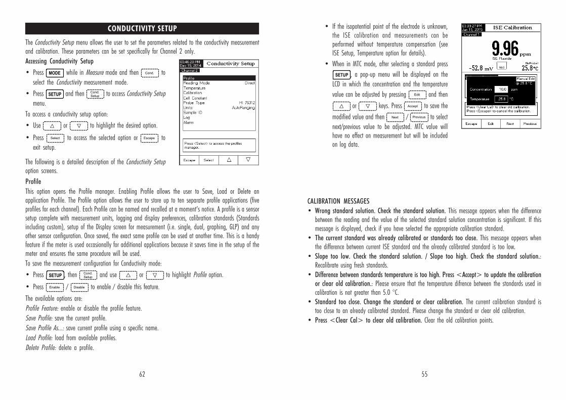
55
• If the isopotential point of the electrode is unknown,the ISE calibration and measurements can beperformed without temperature compensation (seeISE Setup, Temperature option for details).
• When in MTC mode, after selecting a standard press
, a pop-up menu will be displayed on the
LCD in which the concentration and the temperature
value can be adjusted by pressing and then
or keys. Press to save the
modified value and then / to select
next/previous value to be adjusted. MTC value willhave no effect on measurement but will be includedon log data.
CALIBRATION MESSAGES
• Wrong standard solution. Check the standard solution. This message appears when the differencebetween the reading and the value of the selected standard solution concentration is significant. If thismessage is displayed, check if you have selected the appropriate calibration standard.
• The current standard was already calibrated or standards too close. This message appears whenthe difference between current ISE standard and the already calibrated standard is too low.
• Slope too low. Check the standard solution. / Slope too high. Check the standard solution.:Recalibrate using fresh standards.
• Difference between standards temperature is too high. Press <Accept> to update the calibrationor clear old calibration.: Please ensure that the temperature difrence between the standards used incalibration is not greater than 5.0 °C.
• Standard too close. Change the standard or clear calibration. The current calibration standard istoo close to an already calibrated standard. Please change the standard or clear old calibration.
• Press <Clear Cal> to clear old calibration. Clear the old calibration points.
62
CONDUCTIVITY SETUP
The Conductivity Setup menu allows the user to set the parameters related to the conductivity measurementand calibration. These parameters can be set specifically for Channel 2 only.
Accessing Conductivity Setup
• Press while in Measure mode and then to
select the Conductivity measurement mode.
• Press and then to access Conductivity Setup
menu.
To access a conductivity setup option:
• Use or to highlight the desired option.
• Press to access the selected option or to
exit setup.
The following is a detailed description of the Conductivity Setupoption screens.
Profile
This option opens the Profile manager. Enabling Profile allows the user to Save, Load or Delete anapplication Profile. The Profile option allows the user to store up to ten separate profile applications (fiveprofiles for each channel). Each Profile can be named and recalled at a moment’s notice. A profile is a sensorsetup complete with measurement units, logging and display preferences, calibration standards (Standardsincluding custom), setup of the Display screen for measurement (i.e. single, dual, graphing, GLP) and anyother sensor configuration. Once saved, the exact same profile can be used at another time. This is a handyfeature if the meter is used occasionally for additional applications because it saves time in the setup of themeter and ensures the same procedure will be used.
To save the measurement configuration for Conductivity mode:
• Press , then and use or to highlight Profile option.
• Press / to enable / disable this feature.
The available options are:
Profile Feature: enable or disable the profile feature.
Save Profile: save the current profile.
Save Profile As...: save current profile using a specific name.
Load Profile: load from available profiles.
Delete Profile: delete a profile.
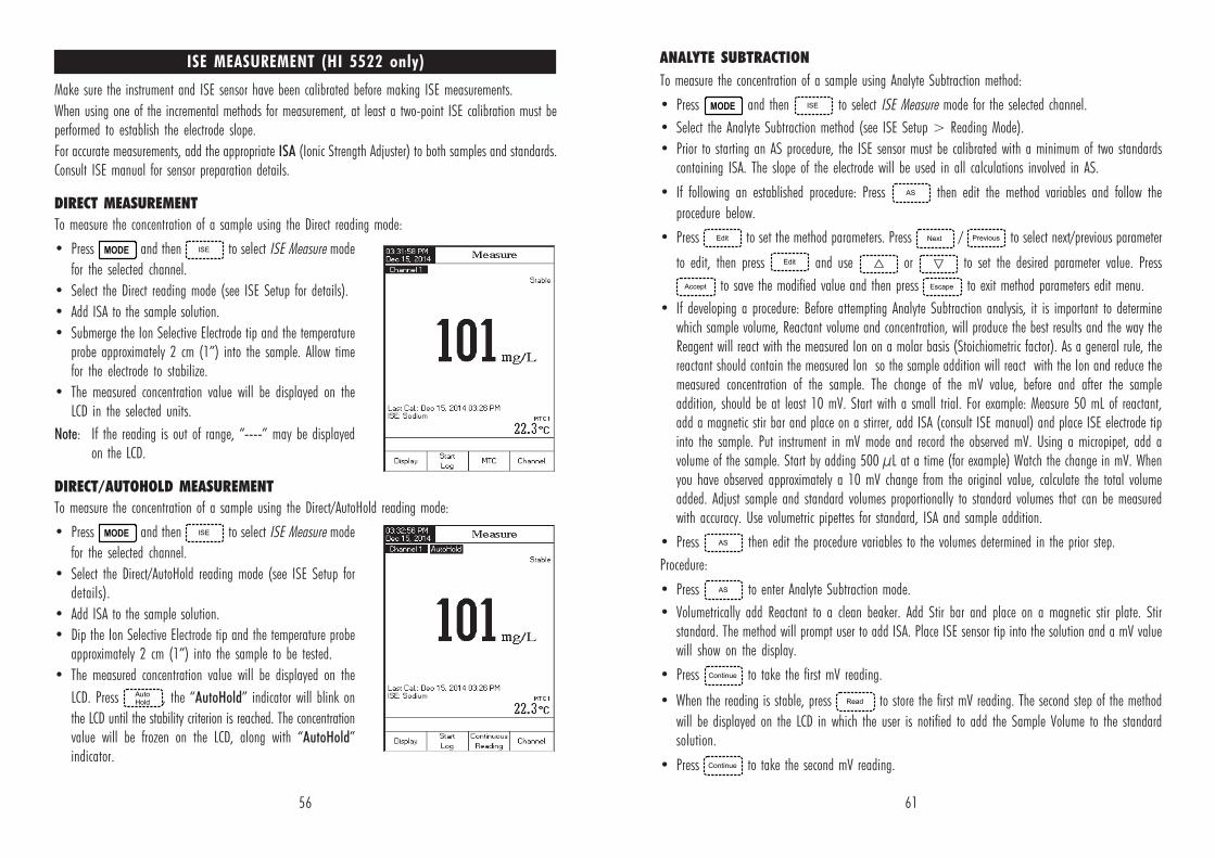
56
ISE MEASUREMENT (HI 5522 only)
Make sure the instrument and ISE sensor have been calibrated before making ISE measurements.
When using one of the incremental methods for measurement, at least a two-point ISE calibration must beperformed to establish the electrode slope.
For accurate measurements, add the appropriate ISA (Ionic Strength Adjuster) to both samples and standards.Consult ISE manual for sensor preparation details.
DIRECT MEASUREMENT
To measure the concentration of a sample using the Direct reading mode:
• Press and then to select ISE Measure mode
for the selected channel.
• Select the Direct reading mode (see ISE Setup for details).
• Add ISA to the sample solution.
• Submerge the Ion Selective Electrode tip and the temperatureprobe approximately 2 cm (1”) into the sample. Allow timefor the electrode to stabilize.
• The measured concentration value will be displayed on theLCD in the selected units.
Note: If the reading is out of range, “----” may be displayedon the LCD.
DIRECT/AUTOHOLD MEASUREMENT
To measure the concentration of a sample using the Direct/AutoHold reading mode:
• Press and then to select ISE Measure mode
for the selected channel.
• Select the Direct/AutoHold reading mode (see ISE Setup fordetails).
• Add ISA to the sample solution.
• Dip the Ion Selective Electrode tip and the temperature probeapproximately 2 cm (1”) into the sample to be tested.
• The measured concentration value will be displayed on the
LCD. Press , the “AutoHold” indicator will blink on
the LCD until the stability criterion is reached. The concentrationvalue will be frozen on the LCD, along with “AutoHold”indicator.
61
ANALYTE SUBTRACTION
To measure the concentration of a sample using Analyte Subtraction method:
• Press and then to select ISE Measure mode for the selected channel.
• Select the Analyte Subtraction method (see ISE Setup > Reading Mode).
• Prior to starting an AS procedure, the ISE sensor must be calibrated with a minimum of two standardscontaining ISA. The slope of the electrode will be used in all calculations involved in AS.
• If following an established procedure: Press then edit the method variables and follow the
procedure below.
• Press to set the method parameters. Press / to select next/previous parameter
to edit, then press and use or to set the desired parameter value. Press
to save the modified value and then press to exit method parameters edit menu.
• If developing a procedure: Before attempting Analyte Subtraction analysis, it is important to determinewhich sample volume, Reactant volume and concentration, will produce the best results and the way theReagent will react with the measured Ion on a molar basis (Stoichiometric factor). As a general rule, thereactant should contain the measured Ion so the sample addition will react with the Ion and reduce themeasured concentration of the sample. The change of the mV value, before and after the sampleaddition, should be at least 10 mV. Start with a small trial. For example: Measure 50 mL of reactant,add a magnetic stir bar and place on a stirrer, add ISA (consult ISE manual) and place ISE electrode tipinto the sample. Put instrument in mV mode and record the observed mV. Using a micropipet, add avolume of the sample. Start by adding 500 µL at a time (for example) Watch the change in mV. Whenyou have observed approximately a 10 mV change from the original value, calculate the total volumeadded. Adjust sample and standard volumes proportionally to standard volumes that can be measuredwith accuracy. Use volumetric pipettes for standard, ISA and sample addition.
• Press then edit the procedure variables to the volumes determined in the prior step.
Procedure:
• Press to enter Analyte Subtraction mode.
• Volumetrically add Reactant to a clean beaker. Add Stir bar and place on a magnetic stir plate. Stirstandard. The method will prompt user to add ISA. Place ISE sensor tip into the solution and a mV valuewill show on the display.
• Press to take the first mV reading.
• When the reading is stable, press to store the first mV reading. The second step of the method
will be displayed on the LCD in which the user is notified to add the Sample Volume to the standardsolution.
• Press to take the second mV reading.
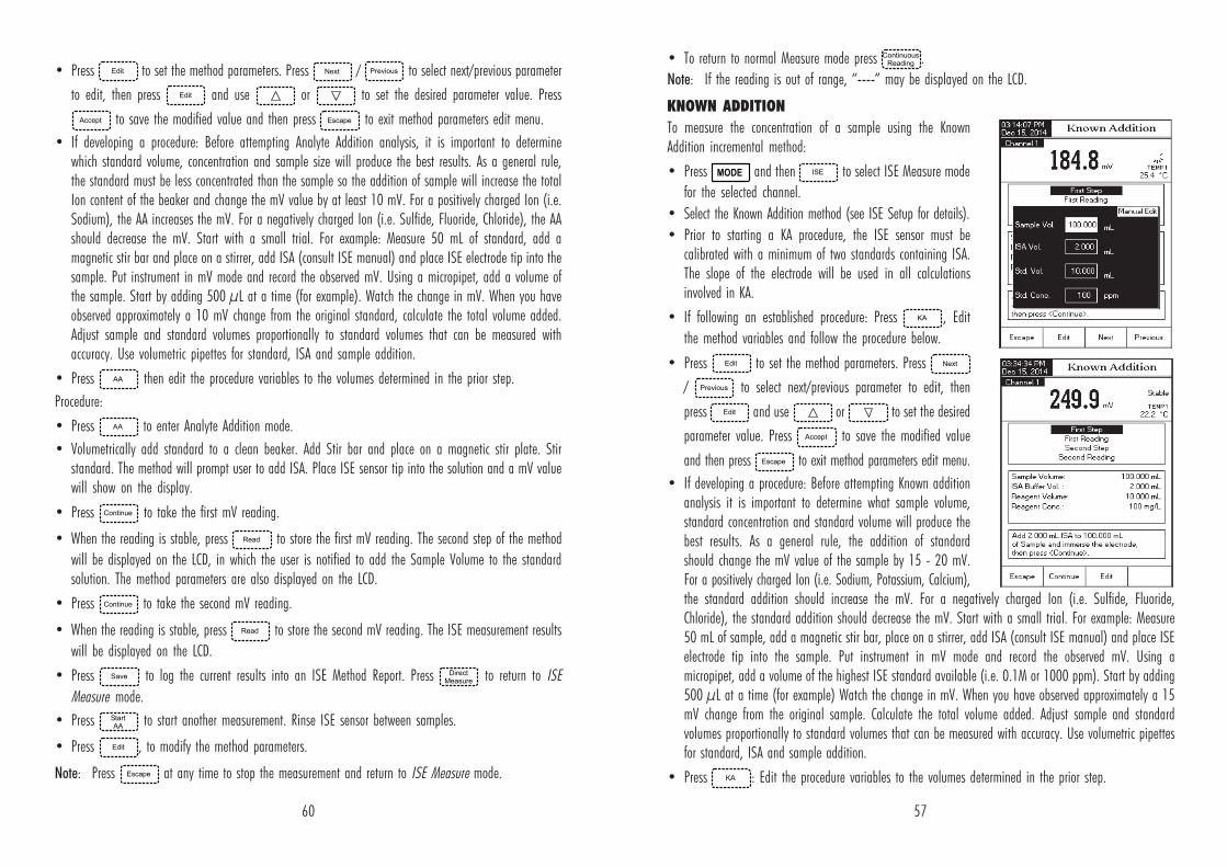
57
• To return to normal Measure mode press .
Note: If the reading is out of range, “----” may be displayed on the LCD.
KNOWN ADDITION
To measure the concentration of a sample using the KnownAddition incremental method:
• Press and then to select ISE Measure mode
for the selected channel.
• Select the Known Addition method (see ISE Setup for details).
• Prior to starting a KA procedure, the ISE sensor must becalibrated with a minimum of two standards containing ISA.The slope of the electrode will be used in all calculationsinvolved in KA.
• If following an established procedure: Press , Edit
the method variables and follow the procedure below.
• Press to set the method parameters. Press
/ to select next/previous parameter to edit, then
press and use or to set the desired
parameter value. Press to save the modified value
and then press to exit method parameters edit menu.
• If developing a procedure: Before attempting Known additionanalysis it is important to determine what sample volume,standard concentration and standard volume will produce thebest results. As a general rule, the addition of standardshould change the mV value of the sample by 15 - 20 mV.For a positively charged Ion (i.e. Sodium, Potassium, Calcium),the standard addition should increase the mV. For a negatively charged Ion (i.e. Sulfide, Fluoride,Chloride), the standard addition should decrease the mV. Start with a small trial. For example: Measure50 mL of sample, add a magnetic stir bar, place on a stirrer, add ISA (consult ISE manual) and place ISEelectrode tip into the sample. Put instrument in mV mode and record the observed mV. Using amicropipet, add a volume of the highest ISE standard available (i.e. 0.1M or 1000 ppm). Start by adding500 µL at a time (for example) Watch the change in mV. When you have observed approximately a 15mV change from the original sample. Calculate the total volume added. Adjust sample and standardvolumes proportionally to standard volumes that can be measured with accuracy. Use volumetric pipettesfor standard, ISA and sample addition.
• Press : Edit the procedure variables to the volumes determined in the prior step.
60
• Press to set the method parameters. Press / to select next/previous parameter
to edit, then press and use or to set the desired parameter value. Press
to save the modified value and then press to exit method parameters edit menu.
• If developing a procedure: Before attempting Analyte Addition analysis, it is important to determinewhich standard volume, concentration and sample size will produce the best results. As a general rule,the standard must be less concentrated than the sample so the addition of sample will increase the totalIon content of the beaker and change the mV value by at least 10 mV. For a positively charged Ion (i.e.Sodium), the AA increases the mV. For a negatively charged Ion (i.e. Sulfide, Fluoride, Chloride), the AAshould decrease the mV. Start with a small trial. For example: Measure 50 mL of standard, add amagnetic stir bar and place on a stirrer, add ISA (consult ISE manual) and place ISE electrode tip into thesample. Put instrument in mV mode and record the observed mV. Using a micropipet, add a volume ofthe sample. Start by adding 500 µL at a time (for example). Watch the change in mV. When you haveobserved approximately a 10 mV change from the original standard, calculate the total volume added.Adjust sample and standard volumes proportionally to standard volumes that can be measured withaccuracy. Use volumetric pipettes for standard, ISA and sample addition.
• Press then edit the procedure variables to the volumes determined in the prior step.
Procedure:
• Press to enter Analyte Addition mode.
• Volumetrically add standard to a clean beaker. Add Stir bar and place on a magnetic stir plate. Stirstandard. The method will prompt user to add ISA. Place ISE sensor tip into the solution and a mV valuewill show on the display.
• Press to take the first mV reading.
• When the reading is stable, press to store the first mV reading. The second step of the method
will be displayed on the LCD, in which the user is notified to add the Sample Volume to the standardsolution. The method parameters are also displayed on the LCD.
• Press to take the second mV reading.
• When the reading is stable, press to store the second mV reading. The ISE measurement results
will be displayed on the LCD.
• Press to log the current results into an ISE Method Report. Press to return to ISE
Measure mode.
• Press to start another measurement. Rinse ISE sensor between samples.
• Press , to modify the method parameters.
Note: Press at any time to stop the measurement and return to ISE Measure mode.
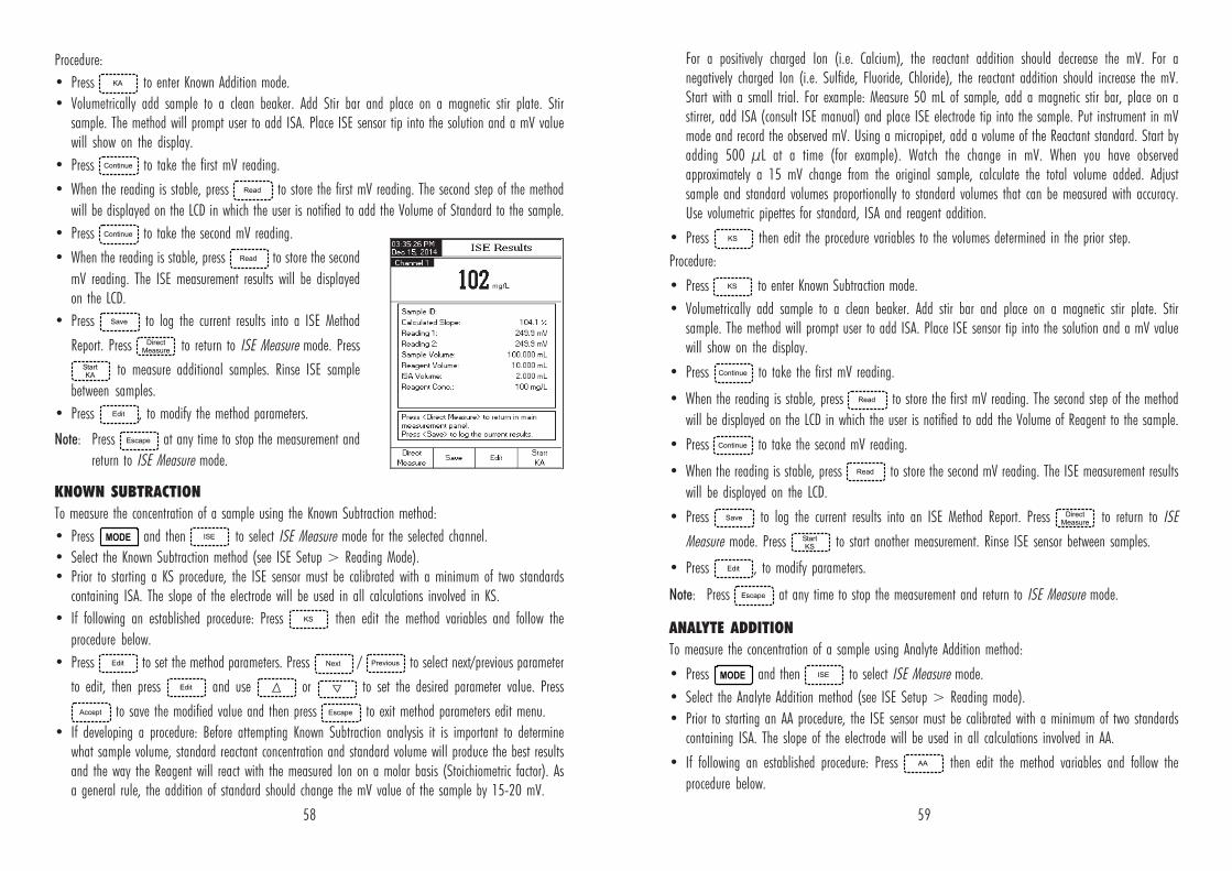
58
Procedure:
• Press to enter Known Addition mode.
• Volumetrically add sample to a clean beaker. Add Stir bar and place on a magnetic stir plate. Stirsample. The method will prompt user to add ISA. Place ISE sensor tip into the solution and a mV valuewill show on the display.
• Press to take the first mV reading.
• When the reading is stable, press to store the first mV reading. The second step of the method
will be displayed on the LCD in which the user is notified to add the Volume of Standard to the sample.
• Press to take the second mV reading.
• When the reading is stable, press to store the second
mV reading. The ISE measurement results will be displayedon the LCD.
• Press to log the current results into a ISE Method
Report. Press to return to ISE Measure mode. Press
to measure additional samples. Rinse ISE sample
between samples.
• Press , to modify the method parameters.
Note: Press at any time to stop the measurement and
return to ISE Measure mode.
KNOWN SUBTRACTION
To measure the concentration of a sample using the Known Subtraction method:
• Press and then to select ISE Measure mode for the selected channel.
• Select the Known Subtraction method (see ISE Setup > Reading Mode).• Prior to starting a KS procedure, the ISE sensor must be calibrated with a minimum of two standards
containing ISA. The slope of the electrode will be used in all calculations involved in KS.
• If following an established procedure: Press then edit the method variables and follow the
procedure below.
• Press to set the method parameters. Press / to select next/previous parameter
to edit, then press and use or to set the desired parameter value. Press
to save the modified value and then press to exit method parameters edit menu.
• If developing a procedure: Before attempting Known Subtraction analysis it is important to determinewhat sample volume, standard reactant concentration and standard volume will produce the best resultsand the way the Reagent will react with the measured Ion on a molar basis (Stoichiometric factor). Asa general rule, the addition of standard should change the mV value of the sample by 15-20 mV.
59
For a positively charged Ion (i.e. Calcium), the reactant addition should decrease the mV. For anegatively charged Ion (i.e. Sulfide, Fluoride, Chloride), the reactant addition should increase the mV.Start with a small trial. For example: Measure 50 mL of sample, add a magnetic stir bar, place on astirrer, add ISA (consult ISE manual) and place ISE electrode tip into the sample. Put instrument in mVmode and record the observed mV. Using a micropipet, add a volume of the Reactant standard. Start byadding 500 µL at a time (for example). Watch the change in mV. When you have observedapproximately a 15 mV change from the original sample, calculate the total volume added. Adjustsample and standard volumes proportionally to standard volumes that can be measured with accuracy.Use volumetric pipettes for standard, ISA and reagent addition.
• Press then edit the procedure variables to the volumes determined in the prior step.
Procedure:
• Press to enter Known Subtraction mode.
• Volumetrically add sample to a clean beaker. Add stir bar and place on a magnetic stir plate. Stirsample. The method will prompt user to add ISA. Place ISE sensor tip into the solution and a mV valuewill show on the display.
• Press to take the first mV reading.
• When the reading is stable, press to store the first mV reading. The second step of the method
will be displayed on the LCD in which the user is notified to add the Volume of Reagent to the sample.
• Press to take the second mV reading.
• When the reading is stable, press to store the second mV reading. The ISE measurement results
will be displayed on the LCD.
• Press to log the current results into an ISE Method Report. Press to return to ISE
Measure mode. Press to start another measurement. Rinse ISE sensor between samples.
• Press , to modify parameters.
Note: Press at any time to stop the measurement and return to ISE Measure mode.
ANALYTE ADDITION
To measure the concentration of a sample using Analyte Addition method:
• Press and then to select ISE Measure mode.
• Select the Analyte Addition method (see ISE Setup > Reading mode).
• Prior to starting an AA procedure, the ISE sensor must be calibrated with a minimum of two standardscontaining ISA. The slope of the electrode will be used in all calculations involved in AA.
• If following an established procedure: Press then edit the method variables and follow the
procedure below.