documentation el95xx - beckhoff · 2.1notes on the documentation ... 5.8pin assignment ......
TRANSCRIPT

Documentation
EL95xx
Power supply terminals
2.12017-05-19
Version:Date:


Product overview – EtherCAT power supply terminals
EL95xx 3Version: 2.1
1 Product overview – EtherCAT power supplyterminals
EL9505 [} 12] (power supply terminal, 5 VDC, 0.5 A)
EL9508 [} 12] (power supply terminal, 8 VDC, 0.5 A)
EL9510 [} 12] (power supply terminal, 10 VDC, 0.5 A)
EL9512 [} 12] (power supply terminal, 12 VDC, 0.5 A)
EL9515 [} 12] (power supply terminal, 15 VDC, 0.5 A)
EL9560 [} 12] (power supply terminal, 24 V / 24 VDC, 0.1 A)

Table of contents
EL95xx4 Version: 2.1
Table of contents1 Product overview – EtherCAT power supply terminals......................................................................... 3
2 Foreword .................................................................................................................................................... 52.1 Notes on the documentation........................................................................................................... 52.2 Safety instructions .......................................................................................................................... 62.3 Documentation issue status............................................................................................................ 72.4 Version identification of EtherCAT devices..................................................................................... 7
3 Product overview..................................................................................................................................... 123.1 Introduction ................................................................................................................................... 123.2 EL9505, EL9508, EL9510, EL9512, EL9515 - Technical data ..................................................... 133.3 EL9560 - Technical data............................................................................................................... 14
4 Basics communication ........................................................................................................................... 154.1 EtherCAT basics........................................................................................................................... 154.2 EtherCAT cabling – wire-bound.................................................................................................... 154.3 EtherCAT State Machine .............................................................................................................. 164.4 CoE Interface................................................................................................................................ 17
5 Mounting and wiring ............................................................................................................................... 225.1 Instructions for ESD protection ..................................................................................................... 225.2 Installation on mounting rails ........................................................................................................ 225.3 Installation instructions for enhanced mechanical load capacity .................................................. 265.4 Connection system ....................................................................................................................... 265.5 Mounting of Passive Terminals..................................................................................................... 305.6 ATEX - Special conditions (standard temperature range) ............................................................ 315.7 ATEX Documentation ................................................................................................................... 325.8 Pin assignment ............................................................................................................................. 33
6 Commissioning........................................................................................................................................ 346.1 Inserting the terminal in the EtherCAT terminal network .............................................................. 346.2 Process data................................................................................................................................. 37
7 Appendix .................................................................................................................................................. 397.1 UL notice....................................................................................................................................... 397.2 Firmware compatibility .................................................................................................................. 407.3 Support and Service ..................................................................................................................... 41

Foreword
EL95xx 5Version: 2.1
2 Foreword
2.1 Notes on the documentation
Intended audience
This description is only intended for the use of trained specialists in control and automation engineering whoare familiar with the applicable national standards.It is essential that the documentation and the following notes and explanations are followed when installingand commissioning these components.It is the duty of the technical personnel to use the documentation published at the respective time of eachinstallation and commissioning.
The responsible staff must ensure that the application or use of the products described satisfy all therequirements for safety, including all the relevant laws, regulations, guidelines and standards.
Disclaimer
The documentation has been prepared with care. The products described are, however, constantly underdevelopment.
We reserve the right to revise and change the documentation at any time and without prior announcement.
No claims for the modification of products that have already been supplied may be made on the basis of thedata, diagrams and descriptions in this documentation.
Trademarks
Beckhoff®, TwinCAT®, EtherCAT®, Safety over EtherCAT®, TwinSAFE®, XFC® and XTS® are registeredtrademarks of and licensed by Beckhoff Automation GmbH.Other designations used in this publication may be trademarks whose use by third parties for their ownpurposes could violate the rights of the owners.
Patent Pending
The EtherCAT Technology is covered, including but not limited to the following patent applications andpatents: EP1590927, EP1789857, DE102004044764, DE102007017835 with corresponding applications orregistrations in various other countries.
The TwinCAT Technology is covered, including but not limited to the following patent applications andpatents: EP0851348, US6167425 with corresponding applications or registrations in various other countries.
EtherCAT® is registered trademark and patented technology, licensed by Beckhoff Automation GmbH,Germany
Copyright
© Beckhoff Automation GmbH & Co. KG, Germany.The reproduction, distribution and utilization of this document as well as the communication of its contents toothers without express authorization are prohibited.Offenders will be held liable for the payment of damages. All rights reserved in the event of the grant of apatent, utility model or design.

Foreword
EL95xx6 Version: 2.1
2.2 Safety instructions
Safety regulations
Please note the following safety instructions and explanations!Product-specific safety instructions can be found on following pages or in the areas mounting, wiring,commissioning etc.
Exclusion of liability
All the components are supplied in particular hardware and software configurations appropriate for theapplication. Modifications to hardware or software configurations other than those described in thedocumentation are not permitted, and nullify the liability of Beckhoff Automation GmbH & Co. KG.
Personnel qualification
This description is only intended for trained specialists in control, automation and drive engineering who arefamiliar with the applicable national standards.
Description of symbols
In this documentation the following symbols are used with an accompanying safety instruction or note. Thesafety instructions must be read carefully and followed without fail!
DANGER
Serious risk of injury!Failure to follow the safety instructions associated with this symbol directly endangers thelife and health of persons.
WARNING
Risk of injury!Failure to follow the safety instructions associated with this symbol endangers the life andhealth of persons.
CAUTION
Personal injuries!Failure to follow the safety instructions associated with this symbol can lead to injuries topersons.
Attention
Damage to the environment or devicesFailure to follow the instructions associated with this symbol can lead to damage to the en-vironment or equipment.
Note
Tip or pointerThis symbol indicates information that contributes to better understanding.

Foreword
EL95xx 7Version: 2.1
2.3 Documentation issue statusVersion Comment2.1 • Update chapter "Notes on the documentation"
• Update chapter "Technical data"• Addenda chapter "Instructions for ESD protection"• Addenda chapter "Installation instructions for enhanced mechanical load capacity"• Chapter "ATEX - Special conditions" replaced with chapter "ATEX - Special
conditions (standard temperature range)"2.0 • Migration
• Update structure1.4 • Update "Technical data"1.3 • Update "Technical data", connection diagram1.2 • Note regarding firmware compatibility inserted1.1 • EL9560 added1.0 • First published0.2 • Corrections and addenda0.1 • Provisional documentation for EL95xx
2.4 Version identification of EtherCAT devices
Designation
A Beckhoff EtherCAT device has a 14-digit designation, made up of
• family key• type• version• revision
Example Family Type Version RevisionEL3314-0000-0016 EL terminal
(12 mm, non-pluggable connectionlevel)
3314 (4-channel thermocoupleterminal)
0000 (basic type) 0016
ES3602-0010-0017 ES terminal(12 mm, pluggableconnection level)
3602 (2-channel voltagemeasurement)
0010 (high-precision version)
0017
CU2008-0000-0000 CU device 2008 (8-port fast ethernet switch) 0000 (basic type) 0000
Notes• The elements mentioned above result in the technical designation. EL3314-0000-0016 is used in the
example below.• EL3314-0000 is the order identifier, in the case of “-0000” usually abbreviated to EL3314. “-0016” is the
EtherCAT revision.• The order identifier is made up of
- family key (EL, EP, CU, ES, KL, CX, etc.)- type (3314)- version (-0000)
• The revision -0016 shows the technical progress, such as the extension of features with regard to theEtherCAT communication, and is managed by Beckhoff.In principle, a device with a higher revision can replace a device with a lower revision, unless specifiedotherwise, e.g. in the documentation.

Foreword
EL95xx8 Version: 2.1
Associated and synonymous with each revision there is usually a description (ESI, EtherCAT SlaveInformation) in the form of an XML file, which is available for download from the Beckhoff web site. From 2014/01 the revision is shown on the outside of the IP20 terminals, see Fig. “EL5021 EL terminal,standard IP20 IO device with batch number and revision ID (since 2014/01)”.
• The type, version and revision are read as decimal numbers, even if they are technically saved inhexadecimal.
Identification number
Beckhoff EtherCAT devices from the different lines have different kinds of identification numbers:
Production lot/batch number/serial number/date code/D number
The serial number for Beckhoff IO devices is usually the 8-digit number printed on the device or on a sticker.The serial number indicates the configuration in delivery state and therefore refers to a whole productionbatch, without distinguishing the individual modules of a batch.
Structure of the serial number: KK YY FF HH
KK - week of production (CW, calendar week)YY - year of productionFF - firmware versionHH - hardware version
Example with Ser. no.: 12063A02: 12 - production week 12 06 - production year 2006 3A - firmware version 3A 02 -hardware version 02
Exceptions can occur in the IP67 area, where the following syntax can be used (see respective devicedocumentation):
Syntax: D ww yy x y z u
D - prefix designationww - calendar weekyy - yearx - firmware version of the bus PCBy - hardware version of the bus PCBz - firmware version of the I/O PCBu - hardware version of the I/O PCB
Example: D.22081501 calendar week 22 of the year 2008 firmware version of bus PCB: 1 hardware versionof bus PCB: 5 firmware version of I/O PCB: 0 (no firmware necessary for this PCB) hardware version of I/OPCB: 1
Unique serial number/ID, ID number
In addition, in some series each individual module has its own unique serial number.
See also the further documentation in the area
• IP67: EtherCAT Box
• Safety: TwinSafe• Terminals with factory calibration certificate and other measuring terminals

Foreword
EL95xx 9Version: 2.1
Examples of markings
Fig. 1: EL5021 EL terminal, standard IP20 IO device with batch number and revision ID (since 2014/01)
Fig. 2: EK1100 EtherCAT coupler, standard IP20 IO device with batch number
Fig. 3: CU2016 switch with batch number
Foreword
EL95xx10 Version: 2.1
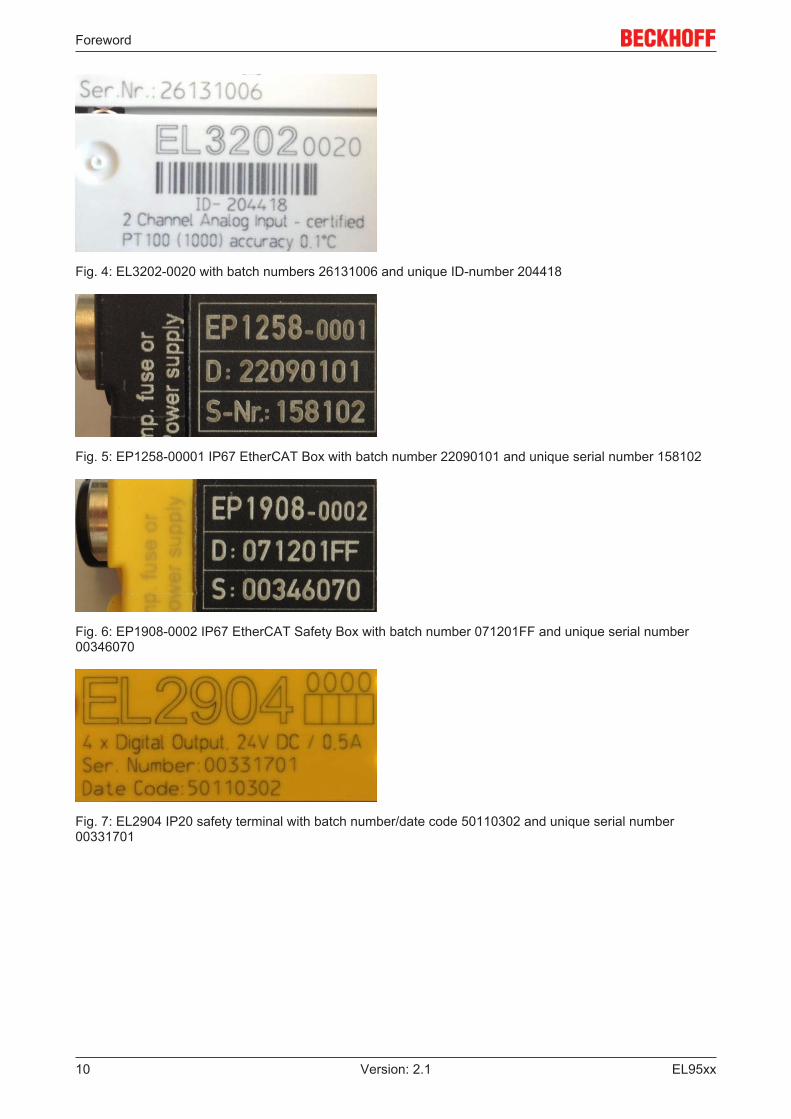
Fig. 4: EL3202-0020 with batch numbers 26131006 and unique ID-number 204418
Fig. 5: EP1258-00001 IP67 EtherCAT Box with batch number 22090101 and unique serial number 158102
Fig. 6: EP1908-0002 IP67 EtherCAT Safety Box with batch number 071201FF and unique serial number00346070
Fig. 7: EL2904 IP20 safety terminal with batch number/date code 50110302 and unique serial number00331701
Foreword
EL95xx 11Version: 2.1
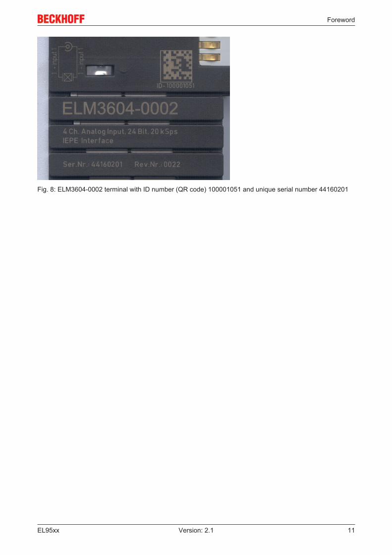
Fig. 8: ELM3604-0002 terminal with ID number (QR code) 100001051 and unique serial number 44160201

Product overview
EL95xx12 Version: 2.1
3 Product overview
3.1 Introduction
Fig. 9: Left: EL9505 (identical pin assignment: EL9508, EL9510, EL9512, EL9515) Right: EL9560
Based on the input voltage (24 VDC), the EL9505, EL9508, EL9510, EL9512 and EL9515 power supplyterminals generate different output voltages, which can be picked up at the terminals. The followingEtherCAT Terminals are also supplied with this voltage via the power contacts. The power LEDs indicate theoperating states of the terminals, short-circuits or overloads are indicated by the overcurrent LEDs. The inputvoltage and the output voltage U0 are not electrically isolated.
The EL9560 power supply unit terminal generates an electrically isolated output voltage from the 24 VDCinput voltage. The input voltage and the output voltage of 500 V are also electrically isolated.
Product overview
EL95xx 13Version: 2.1
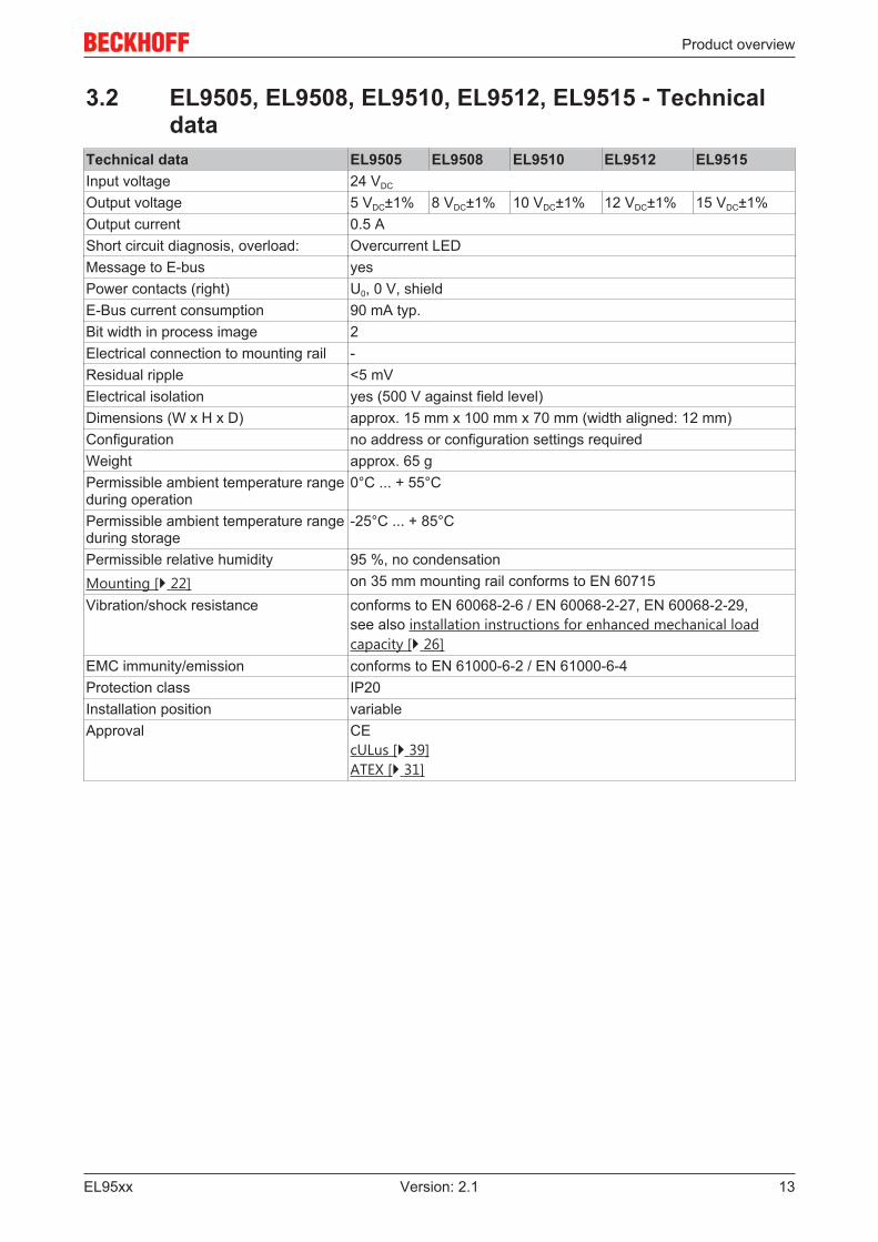
3.2 EL9505, EL9508, EL9510, EL9512, EL9515 - Technicaldata
Technical data EL9505 EL9508 EL9510 EL9512 EL9515Input voltage 24 VDC
Output voltage 5 VDC±1% 8 VDC±1% 10 VDC±1% 12 VDC±1% 15 VDC±1%Output current 0.5 AShort circuit diagnosis, overload: Overcurrent LEDMessage to E-bus yesPower contacts (right) U0, 0 V, shieldE-Bus current consumption 90 mA typ.Bit width in process image 2Electrical connection to mounting rail -Residual ripple <5 mVElectrical isolation yes (500 V against field level)Dimensions (W x H x D) approx. 15 mm x 100 mm x 70 mm (width aligned: 12 mm)Configuration no address or configuration settings requiredWeight approx. 65 gPermissible ambient temperature rangeduring operation
0°C ... + 55°C
Permissible ambient temperature rangeduring storage
-25°C ... + 85°C
Permissible relative humidity 95 %, no condensationMounting [} 22] on 35 mm mounting rail conforms to EN 60715Vibration/shock resistance conforms to EN 60068-2-6 / EN 60068-2-27, EN 60068-2-29,
see also installation instructions for enhanced mechanical loadcapacity [} 26]
EMC immunity/emission conforms to EN 61000-6-2 / EN 61000-6-4Protection class IP20Installation position variableApproval CE
cULus [} 39]ATEX [} 31]
Product overview
EL95xx14 Version: 2.1
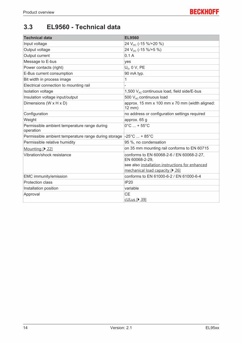
3.3 EL9560 - Technical dataTechnical data EL9560Input voltage 24 VDC (-15 %/+20 %)Output voltage 24 VDC (-15 %/+5 %)Output current 0.1 AMessage to E-bus yesPower contacts (right) U0, 0 V, PEE-Bus current consumption 90 mA typ.Bit width in process image 1Electrical connection to mounting rail -Isolation voltage 1,500 VAC´continuous load, field side/E-busInsulation voltage input/output 500 VAC continuous loadDimensions (W x H x D) approx. 15 mm x 100 mm x 70 mm (width aligned:
12 mm)Configuration no address or configuration settings requiredWeight approx. 65 gPermissible ambient temperature range duringoperation
0°C ... + 55°C
Permissible ambient temperature range during storage -25°C ... + 85°CPermissible relative humidity 95 %, no condensationMounting [} 22] on 35 mm mounting rail conforms to EN 60715Vibration/shock resistance conforms to EN 60068-2-6 / EN 60068-2-27,
EN 60068-2-29,see also installation instructions for enhancedmechanical load capacity [} 26]
EMC immunity/emission conforms to EN 61000-6-2 / EN 61000-6-4Protection class IP20Installation position variableApproval CE
cULus [} 39]
Basics communication
EL95xx 15Version: 2.1
4 Basics communication
4.1 EtherCAT basicsPlease refer to the chapter EtherCAT System Documentation for the EtherCAT fieldbus basics.
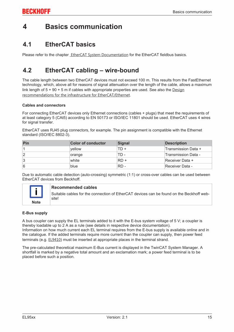
4.2 EtherCAT cabling – wire-boundThe cable length between two EtherCAT devices must not exceed 100 m. This results from the FastEthernettechnology, which, above all for reasons of signal attenuation over the length of the cable, allows a maximumlink length of 5 + 90 + 5 m if cables with appropriate properties are used. See also the Designrecommendations for the infrastructure for EtherCAT/Ethernet.
Cables and connectors
For connecting EtherCAT devices only Ethernet connections (cables + plugs) that meet the requirements ofat least category 5 (CAt5) according to EN 50173 or ISO/IEC 11801 should be used. EtherCAT uses 4 wiresfor signal transfer.
EtherCAT uses RJ45 plug connectors, for example. The pin assignment is compatible with the Ethernetstandard (ISO/IEC 8802-3).
Pin Color of conductor Signal Description1 yellow TD + Transmission Data +2 orange TD - Transmission Data -3 white RD + Receiver Data +6 blue RD - Receiver Data -
Due to automatic cable detection (auto-crossing) symmetric (1:1) or cross-over cables can be used betweenEtherCAT devices from Beckhoff.
Note
Recommended cablesSuitable cables for the connection of EtherCAT devices can be found on the Beckhoff web-site!
E-Bus supply
A bus coupler can supply the EL terminals added to it with the E-bus system voltage of 5 V; a coupler isthereby loadable up to 2 A as a rule (see details in respective device documentation).Information on how much current each EL terminal requires from the E-bus supply is available online and inthe catalogue. If the added terminals require more current than the coupler can supply, then power feedterminals (e.g. EL9410) must be inserted at appropriate places in the terminal strand.
The pre-calculated theoretical maximum E-Bus current is displayed in the TwinCAT System Manager. Ashortfall is marked by a negative total amount and an exclamation mark; a power feed terminal is to beplaced before such a position.

Basics communication
EL95xx16 Version: 2.1
Fig. 10: System manager current calculation
Attention
Malfunction possible!The same ground potential must be used for the E-Bus supply of all EtherCAT terminals ina terminal block!
4.3 EtherCAT State MachineThe state of the EtherCAT slave is controlled via the EtherCAT State Machine (ESM). Depending upon thestate, different functions are accessible or executable in the EtherCAT slave. Specific commands must besent by the EtherCAT master to the device in each state, particularly during the bootup of the slave.
A distinction is made between the following states:
• Init• Pre-Operational• Safe-Operational and• Operational• Boot
The regular state of each EtherCAT slave after bootup is the OP state.
Fig. 11: States of the EtherCAT State Machine

Basics communication
EL95xx 17Version: 2.1
Init
After switch-on the EtherCAT slave in the Init state. No mailbox or process data communication is possible.The EtherCAT master initializes sync manager channels 0 and 1 for mailbox communication.
Pre-Operational (Pre-Op)
During the transition between Init and Pre-Op the EtherCAT slave checks whether the mailbox was initializedcorrectly.
In Pre-Op state mailbox communication is possible, but not process data communication. The EtherCATmaster initializes the sync manager channels for process data (from sync manager channel 2), the FMMUchannels and, if the slave supports configurable mapping, PDO mapping or the sync manager PDOassignment. In this state the settings for the process data transfer and perhaps terminal-specific parametersthat may differ from the default settings are also transferred.
Safe-Operational (Safe-Op)
During transition between Pre-Op and Safe-Op the EtherCAT slave checks whether the sync managerchannels for process data communication and, if required, the distributed clocks settings are correct. Beforeit acknowledges the change of state, the EtherCAT slave copies current input data into the associated DP-RAM areas of the EtherCAT slave controller (ECSC).
In Safe-Op state mailbox and process data communication is possible, although the slave keeps its outputsin a safe state, while the input data are updated cyclically.
Note
Outputs in SAFEOP stateThe default set watchdog monitoring sets the outputs of the module in a safe state - de-pending on the settings in SAFEOP and OP - e.g. in OFF state. If this is prevented by de-activation of the watchdog monitoring in the module, the outputs can be switched or setalso in the SAFEOP state.
Operational (Op)
Before the EtherCAT master switches the EtherCAT slave from Safe-Op to Op it must transfer valid outputdata.
In the Op state the slave copies the output data of the masters to its outputs. Process data and mailboxcommunication is possible.
Boot
In the Boot state the slave firmware can be updated. The Boot state can only be reached via the Init state.
In the Boot state mailbox communication via the file access over EtherCAT (FoE) protocol is possible, but noother mailbox communication and no process data communication.
4.4 CoE Interface
General description
The CoE interface (CANopen over EtherCAT) is used for parameter management of EtherCAT devices.EtherCAT slaves or the EtherCAT master manage fixed (read only) or variable parameters which theyrequire for operation, diagnostics or commissioning.
CoE parameters are arranged in a table hierarchy. In principle, the user has read access via the fieldbus.The EtherCAT master (TwinCAT System Manager) can access the local CoE lists of the slaves viaEtherCAT in read or write mode, depending on the attributes.
Different CoE parameter types are possible, including string (text), integer numbers, Boolean values or largerbyte fields. They can be used to describe a wide range of features. Examples of such parameters includemanufacturer ID, serial number, process data settings, device name, calibration values for analogmeasurement or passwords.

Basics communication
EL95xx18 Version: 2.1
The order is specified in 2 levels via hexadecimal numbering: (main)index, followed by subindex. The valueranges are
• Index: 0x0000 …0xFFFF (0...65535dez)• SubIndex: 0x00…0xFF (0...255dez)
A parameter localized in this way is normally written as 0x8010:07, with preceding "x" to identify thehexadecimal numerical range and a colon between index and subindex.
The relevant ranges for EtherCAT fieldbus users are:
• 0x1000: This is where fixed identity information for the device is stored, including name, manufacturer,serial number etc., plus information about the current and available process data configurations.
• 0x8000: This is where the operational and functional parameters for all channels are stored, such asfilter settings or output frequency.
Other important ranges are:
• 0x4000: In some EtherCAT devices the channel parameters are stored here (as an alternative to the0x8000 range).
• 0x6000: Input PDOs ("input" from the perspective of the EtherCAT master)• 0x7000: Output PDOs ("output" from the perspective of the EtherCAT master)
Note
AvailabilityNot every EtherCAT device must have a CoE list. Simple I/O modules without dedicatedprocessor usually have no variable parameters and therefore no CoE list.
If a device has a CoE list, it is shown in the TwinCAT System Manager as a separate tab with a listing of theelements:
Fig. 12: "CoE Online " tab
The figure above shows the CoE objects available in device "EL2502", ranging from 0x1000 to 0x1600. Thesubindices for 0x1018 are expanded.
Basics communication
EL95xx 19Version: 2.1
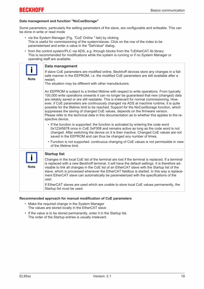
Data management and function "NoCoeStorage"
Some parameters, particularly the setting parameters of the slave, are configurable and writeable. This canbe done in write or read mode
• via the System Manager (Fig. "CoE Online " tab) by clickingThis is useful for commissioning of the system/slaves. Click on the row of the index to beparameterised and enter a value in the "SetValue" dialog.
• from the control system/PLC via ADS, e.g. through blocks from the TcEtherCAT.lib libraryThis is recommended for modifications while the system is running or if no System Manager oroperating staff are available.
Note
Data managementIf slave CoE parameters are modified online, Beckhoff devices store any changes in a fail-safe manner in the EEPROM, i.e. the modified CoE parameters are still available after arestart. The situation may be different with other manufacturers.
An EEPROM is subject to a limited lifetime with respect to write operations. From typically100,000 write operations onwards it can no longer be guaranteed that new (changed) dataare reliably saved or are still readable. This is irrelevant for normal commissioning. How-ever, if CoE parameters are continuously changed via ADS at machine runtime, it is quitepossible for the lifetime limit to be reached. Support for the NoCoeStorage function, whichsuppresses the saving of changed CoE values, depends on the firmware version.Please refer to the technical data in this documentation as to whether this applies to the re-spective device.
• If the function is supported: the function is activated by entering the code word0x12345678 once in CoE 0xF008 and remains active as long as the code word is notchanged. After switching the device on it is then inactive. Changed CoE values are notsaved in the EEPROM and can thus be changed any number of times.
• Function is not supported: continuous changing of CoE values is not permissible in viewof the lifetime limit.
Note
Startup listChanges in the local CoE list of the terminal are lost if the terminal is replaced. If a terminalis replaced with a new Beckhoff terminal, it will have the default settings. It is therefore ad-visable to link all changes in the CoE list of an EtherCAT slave with the Startup list of theslave, which is processed whenever the EtherCAT fieldbus is started. In this way a replace-ment EtherCAT slave can automatically be parameterized with the specifications of theuser.If EtherCAT slaves are used which are unable to store local CoE values permanently, theStartup list must be used.
Recommended approach for manual modification of CoE parameters• Make the required change in the System Manager
The values are stored locally in the EtherCAT slave• If the value is to be stored permanently, enter it in the Startup list.
The order of the Startup entries is usually irrelevant.

Basics communication
EL95xx20 Version: 2.1
Fig. 13: Startup list in the TwinCAT System Manager
The Startup list may already contain values that were configured by the System Manager based on the ESIspecifications. Additional application-specific entries can be created.
Online/offline list
While working with the TwinCAT System Manager, a distinction has to be made whether the EtherCATdevice is "available", i.e. switched on and linked via EtherCAT and therefore online, or whether aconfiguration is created offline without connected slaves.
In both cases a CoE list as shown in Fig. “’CoE online’ tab” is displayed. The connectivity is shown as offline/online.
• If the slave is offline◦ The offline list from the ESI file is displayed. In this case modifications are not meaningful or
possible.◦ The configured status is shown under Identity.◦ No firmware or hardware version is displayed, since these are features of the physical device.◦ Offline is shown in red.
Fig. 14: Offline list
Basics communication
EL95xx 21Version: 2.1
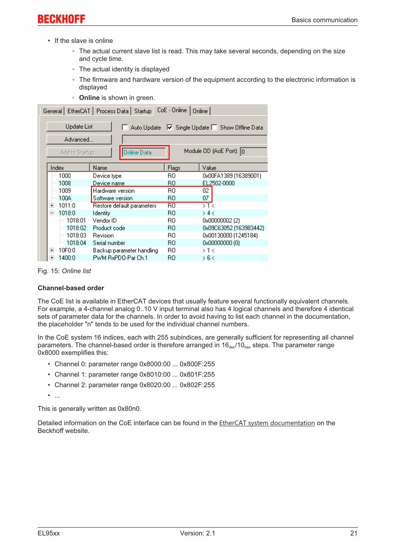
• If the slave is online◦ The actual current slave list is read. This may take several seconds, depending on the size
and cycle time.◦ The actual identity is displayed◦ The firmware and hardware version of the equipment according to the electronic information is
displayed◦ Online is shown in green.
Fig. 15: Online list
Channel-based order
The CoE list is available in EtherCAT devices that usually feature several functionally equivalent channels.For example, a 4-channel analog 0..10 V input terminal also has 4 logical channels and therefore 4 identicalsets of parameter data for the channels. In order to avoid having to list each channel in the documentation,the placeholder "n" tends to be used for the individual channel numbers.
In the CoE system 16 indices, each with 255 subindices, are generally sufficient for representing all channelparameters. The channel-based order is therefore arranged in 16dec/10hex steps. The parameter range0x8000 exemplifies this:
• Channel 0: parameter range 0x8000:00 ... 0x800F:255• Channel 1: parameter range 0x8010:00 ... 0x801F:255• Channel 2: parameter range 0x8020:00 ... 0x802F:255• ...
This is generally written as 0x80n0.
Detailed information on the CoE interface can be found in the EtherCAT system documentation on theBeckhoff website.

Mounting and wiring
EL95xx22 Version: 2.1
5 Mounting and wiring
5.1 Instructions for ESD protection
Attention
Destruction of the devices by electrostatic discharge possible!The devices contain components at risk from electrostatic discharge caused by improperhandling.ü Please ensure you are electrostatically discharged and avoid touching the contacts of
the device directly.a) Avoid contact with highly insulating materials (synthetic fibers, plastic film etc.).b) Surroundings (working place, packaging and personnel) should by grounded probably,
when handling with the devices.
c) Each assembly must be terminated at the right hand end with an EL9011 bus end cap,to ensure the protection class and ESD protection.
Fig. 16: Spring contacts of the Beckhoff I/O components
5.2 Installation on mounting rails
WARNING
Risk of electric shock and damage of device!Bring the bus terminal system into a safe, powered down state before starting installation,disassembly or wiring of the Bus Terminals!

Mounting and wiring
EL95xx 23Version: 2.1
Assembly
Fig. 17: Attaching on mounting rail
The Bus Coupler and Bus Terminals are attached to commercially available 35 mm mounting rails (DIN railsaccording to EN 60715) by applying slight pressure:
1. First attach the Fieldbus Coupler to the mounting rail.2. The Bus Terminals are now attached on the right-hand side of the Fieldbus Coupler. Join the compo-
nents with tongue and groove and push the terminals against the mounting rail, until the lock clicksonto the mounting rail.If the Terminals are clipped onto the mounting rail first and then pushed together without tongue andgroove, the connection will not be operational! When correctly assembled, no significant gap shouldbe visible between the housings.
Note
Fixing of mounting railsThe locking mechanism of the terminals and couplers extends to the profile of the mountingrail. At the installation, the locking mechanism of the components must not come into con-flict with the fixing bolts of the mounting rail. To mount the mounting rails with a height of7.5 mm under the terminals and couplers, you should use flat mounting connections (e.g.countersunk screws or blind rivets).

Mounting and wiring
EL95xx24 Version: 2.1
Disassembly
Fig. 18: Disassembling of terminal
Each terminal is secured by a lock on the mounting rail, which must be released for disassembly:
1. Pull the terminal by its orange-colored lugs approximately 1 cm away from the mounting rail. In doingso for this terminal the mounting rail lock is released automatically and you can pull the terminal out ofthe bus terminal block easily without excessive force.
2. Grasp the released terminal with thumb and index finger simultaneous at the upper and lower groovedhousing surfaces and pull the terminal out of the bus terminal block.
Connections within a bus terminal block
The electric connections between the Bus Coupler and the Bus Terminals are automatically realized byjoining the components:
• The six spring contacts of the K-Bus/E-Bus deal with the transfer of the data and the supply of the BusTerminal electronics.
• The power contacts deal with the supply for the field electronics and thus represent a supply rail withinthe bus terminal block. The power contacts are supplied via terminals on the Bus Coupler (up to 24 V)or for higher voltages via power feed terminals.
Note
Power ContactsDuring the design of a bus terminal block, the pin assignment of the individual Bus Termi-nals must be taken account of, since some types (e.g. analog Bus Terminals or digital 4-channel Bus Terminals) do not or not fully loop through the power contacts. Power FeedTerminals (KL91xx, KL92xx or EL91xx, EL92xx) interrupt the power contacts and thus rep-resent the start of a new supply rail.
PE power contact
The power contact labeled PE can be used as a protective earth. For safety reasons this contact mates firstwhen plugging together, and can ground short-circuit currents of up to 125 A.

Mounting and wiring
EL95xx 25Version: 2.1
Fig. 19: Power contact on left side
Attention
Possible damage of the deviceNote that, for reasons of electromagnetic compatibility, the PE contacts are capacitativelycoupled to the mounting rail. This may lead to incorrect results during insulation testing orto damage on the terminal (e.g. disruptive discharge to the PE line during insulation testingof a consumer with a nominal voltage of 230 V). For insulation testing, disconnect the PEsupply line at the Bus Coupler or the Power Feed Terminal! In order to decouple furtherfeed points for testing, these Power Feed Terminals can be released and pulled at least10 mm from the group of terminals.
WARNING
Risk of electric shock!The PE power contact must not be used for other potentials!

Mounting and wiring
EL95xx26 Version: 2.1
5.3 Installation instructions for enhanced mechanical loadcapacity
WARNING
Risk of injury through electric shock and damage to the device!Bring the Bus Terminal system into a safe, de-energized state before starting mounting,disassembly or wiring of the Bus Terminals!
Additional checks
The terminals have undergone the following additional tests:
Verification ExplanationVibration 10 frequency runs in 3 axes
6 Hz < f < 60 Hz displacement 0.35 mm, constant amplitude60.1 Hz < f < 500 Hz acceleration 5 g, constant amplitude
Shocks 1000 shocks in each direction, in 3 axes25 g, 6 ms
Additional installation instructions
For terminals with enhanced mechanical load capacity, the following additional installation instructions apply:
• The enhanced mechanical load capacity is valid for all permissible installation positions• Use a mounting rail according to EN 60715 TH35-15• Fix the terminal segment on both sides of the mounting rail with a mechanical fixture, e.g. an earth
terminal or reinforced end clamp• The maximum total extension of the terminal segment (without coupler) is:
64 terminals (12 mm mounting with) or 32 terminals (24 mm mounting with)• Avoid deformation, twisting, crushing and bending of the mounting rail during edging and installation of
the rail• The mounting points of the mounting rail must be set at 5 cm intervals• Use countersunk head screws to fasten the mounting rail• The free length between the strain relief and the wire connection should be kept as short as possible. A
distance of approx. 10 cm should be maintained to the cable duct.
5.4 Connection system
WARNING
Risk of electric shock and damage of device!Bring the bus terminal system into a safe, powered down state before starting installation,disassembly or wiring of the Bus Terminals!
Overview
The Bus Terminal system offers different connection options for optimum adaptation to the respectiveapplication:
• The terminals of KLxxxx and ELxxxx series with standard wiring include electronics and connectionlevel in a single enclosure.
• The terminals of KSxxxx and ESxxxx series feature a pluggable connection level and enable steadywiring while replacing.
• The High Density Terminals (HD Terminals) include electronics and connection level in a singleenclosure and have advanced packaging density.

Mounting and wiring
EL95xx 27Version: 2.1
Standard wiring
Fig. 20: Standard wiring
The terminals of KLxxxx and ELxxxx series have been tried and tested for years.They feature integrated screwless spring force technology for fast and simple assembly.
Pluggable wiring
Fig. 21: Pluggable wiring
The terminals of KSxxxx and ESxxxx series feature a pluggable connection level.The assembly and wiring procedure for the KS series is the same as for the KLxxxx and ELxxxx series.The KS/ES series terminals enable the complete wiring to be removed as a plug connector from the top ofthe housing for servicing.The lower section can be removed from the terminal block by pulling the unlocking tab. Insert the new component and plug in the connector with the wiring. This reduces the installation time andeliminates the risk of wires being mixed up.
The familiar dimensions of the terminal only had to be changed slightly. The new connector adds about 3mm. The maximum height of the terminal remains unchanged.
A tab for strain relief of the cable simplifies assembly in many applications and prevents tangling of individualconnection wires when the connector is removed.
Conductor cross sections between 0.08 mm2 and 2.5 mm2 can continue to be used with the proven springforce technology.
The overview and nomenclature of the product names for KSxxxx and ESxxxx series has been retained asknown from KLxxxx and ELxxxx series.
High Density Terminals (HD Terminals)
Fig. 22: High Density Terminals
The Bus Terminals from these series with 16 connection points are distinguished by a particularly compactdesign, as the packaging density is twice as large as that of the standard 12 mm Bus Terminals. Massiveconductors and conductors with a wire end sleeve can be inserted directly into the spring loaded terminalpoint without tools.

Mounting and wiring
EL95xx28 Version: 2.1
Note
Wiring HD TerminalsThe High Density (HD) Terminals of the KLx8xx and ELx8xx series doesn't support steadywiring.
Ultrasonically "bonded" (ultrasonically welded) conductors
Note
Ultrasonically “bonded" conductorsIt is also possible to connect the Standard and High Density Terminals with ultrasonically"bonded" (ultrasonically welded) conductors. In this case, please note the tables concern-ing the wire-size width [} 28] below!
Wiring
Terminals for standard wiring ELxxxx/KLxxxx and for pluggable wiring ESxxxx/KSxxxx
Fig. 23: Mounting a cable on a terminal connection
Up to eight connections enable the connection of solid or finely stranded cables to the Bus Terminals. Theterminals are implemented in spring force technology. Connect the cables as follows:
1. Open a spring-loaded terminal by slightly pushing with a screwdriver or a rod into the square openingabove the terminal.
2. The wire can now be inserted into the round terminal opening without any force.3. The terminal closes automatically when the pressure is released, holding the wire securely and per-
manently.
Terminal housing ELxxxx, KLxxxx ESxxxx, KSxxxxWire size width 0.08 ... 2,5 mm2 0.08 ... 2.5 mm2
Wire stripping length 8 ... 9 mm 9 ... 10 mm
Mounting and wiring
EL95xx 29Version: 2.1
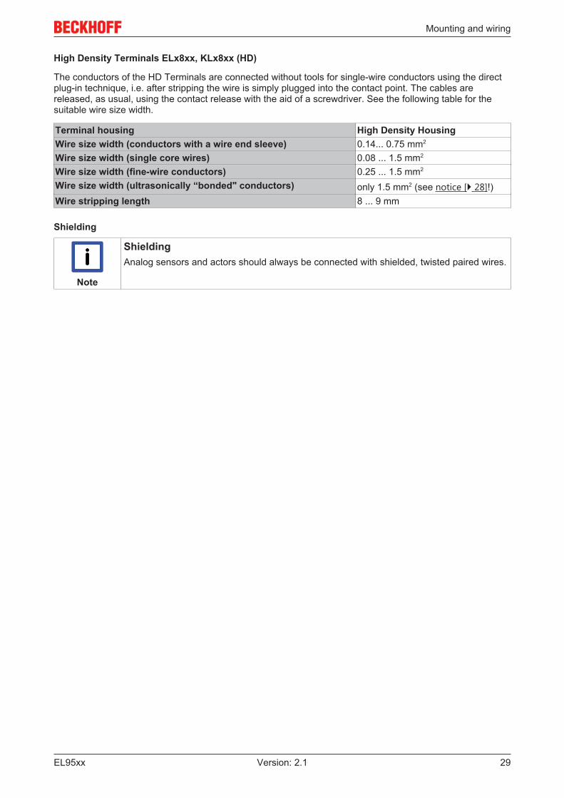
High Density Terminals ELx8xx, KLx8xx (HD)
The conductors of the HD Terminals are connected without tools for single-wire conductors using the directplug-in technique, i.e. after stripping the wire is simply plugged into the contact point. The cables arereleased, as usual, using the contact release with the aid of a screwdriver. See the following table for thesuitable wire size width.
Terminal housing High Density HousingWire size width (conductors with a wire end sleeve) 0.14... 0.75 mm2
Wire size width (single core wires) 0.08 ... 1.5 mm2
Wire size width (fine-wire conductors) 0.25 ... 1.5 mm2
Wire size width (ultrasonically “bonded" conductors) only 1.5 mm2 (see notice [} 28]!)Wire stripping length 8 ... 9 mm
Shielding
Note
ShieldingAnalog sensors and actors should always be connected with shielded, twisted paired wires.

Mounting and wiring
EL95xx30 Version: 2.1
5.5 Mounting of Passive Terminals
Note
Hint for mounting passive terminalsEtherCAT Terminals (ELxxxx / ESxxxx), which do not take an active part in data transferwithin the bus terminal block are so called Passive Terminals. The Passive Terminals haveno current consumption out of the E-Bus To ensure an optimal data transfer, you must notdirectly string together more than 2 Passive Terminals!
Examples for mounting passive terminals (highlighted)
Fig. 24: Correct configuration
Fig. 25: Incorrect configuration

Mounting and wiring
EL95xx 31Version: 2.1
5.6 ATEX - Special conditions (standard temperaturerange)
WARNING
Observe the special conditions for the intended use of Beckhoff fieldbuscomponents with standard temperature range in potentially explosive areas(directive 94/9/EU)!
• The certified components are to be installed in a suitable housing that guarantees aprotection class of at least IP54 in accordance with EN 60529! The environmental con-ditions during use are thereby to be taken into account!
• If the temperatures during rated operation are higher than 70°C at the feed-in points ofcables, lines or pipes, or higher than 80°C at the wire branching points, then cablesmust be selected whose temperature data correspond to the actual measured tempera-ture values!
• Observe the permissible ambient temperature range of 0 to 55°C for the use of Beck-hoff fieldbus components standard temperature range in potentially explosive areas!
• Measures must be taken to protect against the rated operating voltage being exceededby more than 40% due to short-term interference voltages!
• The individual terminals may only be unplugged or removed from the Bus Terminal sys-tem if the supply voltage has been switched off or if a non-explosive atmosphere is en-sured!
• The connections of the certified components may only be connected or disconnected ifthe supply voltage has been switched off or if a non-explosive atmosphere is ensured!
• The fuses of the KL92xx/EL92xx power feed terminals may only be exchanged if thesupply voltage has been switched off or if a non-explosive atmosphere is ensured!
• Address selectors and ID switches may only be adjusted if the supply voltage has beenswitched off or if a non-explosive atmosphere is ensured!
Standards
The fundamental health and safety requirements are fulfilled by compliance with the following standards:
• EN 60079-0:2012+A11:2013• EN 60079-15:2010
Marking
The Beckhoff fieldbus components with standard temperature range certified for potentially explosive areasbear one of the following markings:
II 3G KEMA 10ATEX0075 X Ex nA IIC T4 Gc Ta: 0 … 55°C
or
II 3G KEMA 10ATEX0075 X Ex nC IIC T4 Gc Ta: 0 … 55°C

Mounting and wiring
EL95xx32 Version: 2.1
5.7 ATEX Documentation
Note
Notes about operation of the Beckhoff terminal systems in potentially explo-sive areas (ATEX)Pay also attention to the continuative documentation
Notes about operation of the Beckhoff terminal systems in potentially explosive areas(ATEX)
that is available in the download area of the Beckhoff homepage http:\\www.beckhoff.com!

Mounting and wiring
EL95xx 33Version: 2.1
5.8 Pin assignment
Fig. 26: Pin assignment based on EL9505 as an example
Terminal point DescriptionName No.+24 V 1 +24 V input voltageOutput U0 2 Pickup of output voltage U0 (linked to terminal point 6 and power contact U0)Output 0 V 3 Pickup of output voltage 0 V (linked to terminal point 7 and power contact 0 V)Shield / PE 4 Pickup of shielding / PE (linked to terminal point 8 and power contact shielding /
PE)0 V 5 0 V input voltageOutput U0 6 Pickup of output voltage U0 (linked to terminal point 2 and power contact U0)Output 0 V 7 Pickup of output voltage 0 V (linked to terminal point 3 and power contact 0 V)Shield / PE 8 Pickup of shielding / PE (linked to terminal point 4 and power contact shielding /
PE)
Commissioning
EL95xx34 Version: 2.1
6 Commissioning
6.1 Inserting the terminal in the EtherCAT terminal network(Master: TwinCAT 2.1x)
Note
Installation of the latest XML device descriptionPlease ensure that you have installed the corresponding latest XML device description inTwinCAT. This can be downloaded from the Beckhoff Website and installed according tothe installation instructions.
The configuration tree in the Beckhoff TwinCAT System Manager can be created in 2 ways:
• by scanning of existing hardware (referred to as “online”), or• by manually inserting/appending fieldbus devices, couplers and slaves.
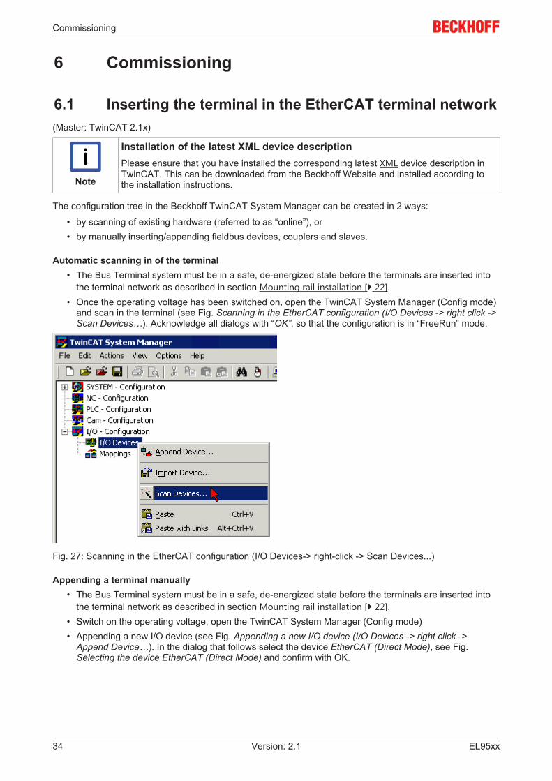
Automatic scanning in of the terminal• The Bus Terminal system must be in a safe, de-energized state before the terminals are inserted into
the terminal network as described in section Mounting rail installation [} 22].• Once the operating voltage has been switched on, open the TwinCAT System Manager (Config mode)
and scan in the terminal (see Fig. Scanning in the EtherCAT configuration (I/O Devices -> right click ->Scan Devices…). Acknowledge all dialogs with “OK”, so that the configuration is in “FreeRun” mode.
Fig. 27: Scanning in the EtherCAT configuration (I/O Devices-> right-click -> Scan Devices...)
Appending a terminal manually• The Bus Terminal system must be in a safe, de-energized state before the terminals are inserted into
the terminal network as described in section Mounting rail installation [} 22].• Switch on the operating voltage, open the TwinCAT System Manager (Config mode)• Appending a new I/O device (see Fig. Appending a new I/O device (I/O Devices -> right click ->
Append Device…). In the dialog that follows select the device EtherCAT (Direct Mode), see Fig.Selecting the device EtherCAT (Direct Mode) and confirm with OK.

Commissioning
EL95xx 35Version: 2.1
Fig. 28: Appending a new I/O device (I/O Devices-> right-click -> Append Device...)
Fig. 29: Selecting the device EtherCAT (Direct Mode)
• Appending a new box (see Fig. Appending a new box (Device -> right click -> Append Box…)). In thedialog that follows select an EK1100 system coupler, for example (see Fig. Selecting a system coupler(e.g. EK1100)) and confirm with OK.
Fig. 30: Appending a new box (Device -> right-click -> Append Box... )

Commissioning
EL95xx36 Version: 2.1
Fig. 31: Selecting a system coupler (e.g. EK1100)
• Appending a new box (see Fig. Appending a new box (Device -> right click -> Append Box…)). In thedialog that follows select the EL95xx, (see Fig. Selecting the terminal, e.g. EL9505) and confirm withOK.
• The terminal is added in the TwinCAT tree (see Fig. Terminal in the TwinCAT tree).
Fig. 32: Appending a new box (Device -> right-click -> Append Box... )

Commissioning
EL95xx 37Version: 2.1
Fig. 33: Selecting the terminal, e.g. EL9505
Fig. 34: Terminal in the TwinCAT tree
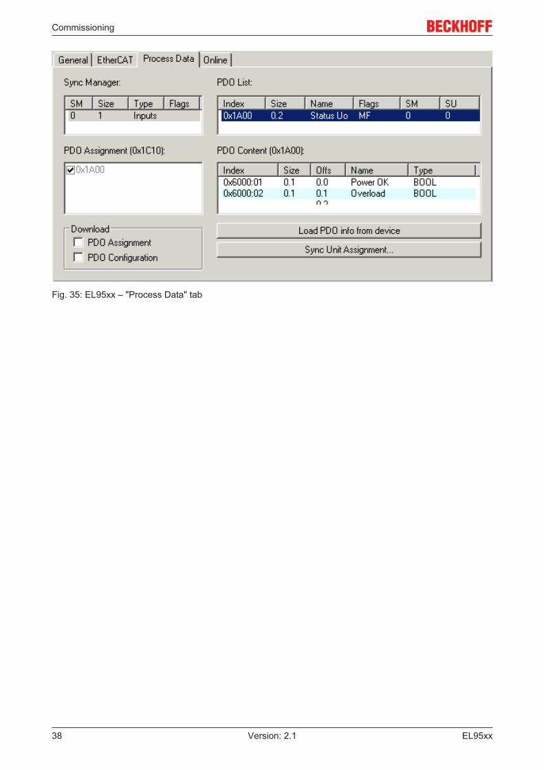
6.2 Process dataThe "Process Data" tab of the EL95xx in the TwinCAT System Manager shows the PDO list of the EL95xxwith the corresponding input objects. The width in the process image is 2 bits.The index 0x1A00 ("Status U0") contains the two boolean input objects "Power OK" (0x6000:01) for checkingthe output voltage and "Overload" (0x6000:02) for the overvoltage display.
Commissioning
EL95xx38 Version: 2.1
Fig. 35: EL95xx – "Process Data" tab

Appendix
EL95xx 39Version: 2.1
7 Appendix
7.1 UL noticeApplicationBeckhoff EtherCAT modules are intended for use with Beckhoff’s UL Listed EtherCAT Sys-tem only.
ExaminationFor cULus examination, the Beckhoff I/O System has only been investigated for risk of fireand electrical shock (in accordance with UL508 and CSA C22.2 No. 142).
For devices with Ethernet connectorsNot for connection to telecommunication circuits.
Basic principles
Two UL certificates are met in the Beckhoff EtherCAT product range, depending upon the components:
• UL certification according to UL508 Devices with this kind of certification are marked by this sign:
Almost all current EtherCAT products (as at 2010/05) are UL certified without restrictions.
• UL certification according to UL508 with limited power consumptionThe current consumed by the device is limited to a max. possible current consumption of 4 A. Deviceswith this kind of certification are marked by this sign:
Almost all current EtherCAT products (as at 2010/05) are UL certified without restrictions.
Application
If terminals certified with restrictions are used, then the current consumption at 24 V DC must be limitedaccordingly by means of supply
• from an isolated source protected by a fuse of max. 4A (according to UL248) or• from a voltage supply complying with NEC class 2.
A voltage source complying with NEC class 2 may not be connected in series or parallel with anotherNEC class 2 compliant voltage supply!
These requirements apply to the supply of all EtherCAT bus couplers, power adaptor terminals, BusTerminals and their power contacts.

Appendix
EL95xx40 Version: 2.1
7.2 Firmware compatibilityThe terminals of the EL95xx series have no firmware.

Appendix
EL95xx 41Version: 2.1
7.3 Support and ServiceBeckhoff and their partners around the world offer comprehensive support and service, making available fastand competent assistance with all questions related to Beckhoff products and system solutions.
Beckhoff's branch offices and representatives
Please contact your Beckhoff branch office or representative for local support and service on Beckhoffproducts!
The addresses of Beckhoff's branch offices and representatives round the world can be found on her internetpages:http://www.beckhoff.com
You will also find further documentation for Beckhoff components there.
Beckhoff Headquarters
Beckhoff Automation GmbH & Co. KG
Huelshorstweg 2033415 VerlGermany
Phone: +49(0)5246/963-0Fax: +49(0)5246/963-198e-mail: [email protected]
Beckhoff Support
Support offers you comprehensive technical assistance, helping you not only with the application ofindividual Beckhoff products, but also with other, wide-ranging services:
• support• design, programming and commissioning of complex automation systems• and extensive training program for Beckhoff system components
Hotline: +49(0)5246/963-157Fax: +49(0)5246/963-9157e-mail: [email protected]
Beckhoff Service
The Beckhoff Service Center supports you in all matters of after-sales service:
• on-site service• repair service• spare parts service• hotline service
Hotline: +49(0)5246/963-460Fax: +49(0)5246/963-479e-mail: [email protected]

List of illustrations
EL95xx42 Version: 2.1
List of illustrationsFig. 1 EL5021 EL terminal, standard IP20 IO device with batch number and revision ID (since
2014/01)....................................................................................................................................... 9Fig. 2 EK1100 EtherCAT coupler, standard IP20 IO device with batch number ................................... 9Fig. 3 CU2016 switch with batch number .............................................................................................. 9Fig. 4 EL3202-0020 with batch numbers 26131006 and unique ID-number 204418 ............................ 10Fig. 5 EP1258-00001 IP67 EtherCAT Box with batch number 22090101 and unique serial number
158102......................................................................................................................................... 10Fig. 6 EP1908-0002 IP67 EtherCAT Safety Box with batch number 071201FF and unique serial
number 00346070........................................................................................................................ 10Fig. 7 EL2904 IP20 safety terminal with batch number/date code 50110302 and unique serial num-
ber 00331701............................................................................................................................... 10Fig. 8 ELM3604-0002 terminal with ID number (QR code) 100001051 and unique serial number
44160201..................................................................................................................................... 11Fig. 9 Left: EL9505 (identical pin assignment: EL9508, EL9510, EL9512, EL9515) Right: EL9560 ..... 12Fig. 10 System manager current calculation .......................................................................................... 16Fig. 11 States of the EtherCAT State Machine........................................................................................ 16Fig. 12 "CoE Online " tab ........................................................................................................................ 18Fig. 13 Startup list in the TwinCAT System Manager ............................................................................. 20Fig. 14 Offline list ..................................................................................................................................... 20Fig. 15 Online list .................................................................................................................................... 21Fig. 16 Spring contacts of the Beckhoff I/O components......................................................................... 22Fig. 17 Attaching on mounting rail ........................................................................................................... 23Fig. 18 Disassembling of terminal............................................................................................................ 24Fig. 19 Power contact on left side............................................................................................................ 25Fig. 20 Standard wiring............................................................................................................................ 27Fig. 21 Pluggable wiring .......................................................................................................................... 27Fig. 22 High Density Terminals................................................................................................................ 27Fig. 23 Mounting a cable on a terminal connection ................................................................................. 28Fig. 24 Correct configuration .................................................................................................................. 30Fig. 25 Incorrect configuration ................................................................................................................ 30Fig. 26 Pin assignment based on EL9505 as an example....................................................................... 33Fig. 27 Scanning in the EtherCAT configuration (I/O Devices-> right-click -> Scan Devices...).............. 34Fig. 28 Appending a new I/O device (I/O Devices-> right-click -> Append Device...).............................. 35Fig. 29 Selecting the device EtherCAT (Direct Mode) ............................................................................. 35Fig. 30 Appending a new box (Device -> right-click -> Append Box... ) .................................................. 35Fig. 31 Selecting a system coupler (e.g. EK1100)................................................................................... 36Fig. 32 Appending a new box (Device -> right-click -> Append Box... ) .................................................. 36Fig. 33 Selecting the terminal, e.g. EL9505............................................................................................. 37Fig. 34 Terminal in the TwinCAT tree ...................................................................................................... 37Fig. 35 EL95xx – "Process Data" tab....................................................................................................... 38