documentation function description - beckhoff...for your safety 10 version: 1.5 function description...
TRANSCRIPT

Documentation
Function description
for servo drives of the series AX5000
1.52018-05-15
Version:Date:


Table of contents
Function description 3Version: 1.5
Table of contents1 Foreword .................................................................................................................................................... 7
1.1 Documentation Issue Status........................................................................................................... 71.2 Notes on the documentation........................................................................................................... 8
2 For your safety........................................................................................................................................... 92.1 Staff qualification ............................................................................................................................ 92.2 Description of symbols.................................................................................................................. 10
3 Asynchronous motors - Special functions ........................................................................................... 113.1 P/I breakdown protection controller (BPC) ................................................................................... 113.2 General information ...................................................................................................................... 12
3.2.1 Functionality from firmware v2.03 .................................................................................... 133.2.2 Configuration.................................................................................................................... 14
4 Acceleration pre-control ......................................................................................................................... 15
5 Change to compatible type..................................................................................................................... 175.1 Functional description................................................................................................................... 195.2 Term definitions ............................................................................................................................ 21
6 Digital inputs and outputs ...................................................................................................................... 226.1 Diagnostic output .......................................................................................................................... 226.2 Hardware-Enable.......................................................................................................................... 236.3 Limit switch monitoring ................................................................................................................. 246.4 Ready to operate .......................................................................................................................... 256.5 Digital output control word ............................................................................................................ 25
7 Comissioning a Generic Encoder with BISS-C Interface..................................................................... 267.1 Preface ......................................................................................................................................... 267.2 Encoder-Interface ......................................................................................................................... 267.3 Wiring............................................................................................................................................ 277.4 Required Data for Comissioning................................................................................................... 277.5 Selecting the Feedback ................................................................................................................ 287.6 Adjusting Encoder specific Settings.............................................................................................. 287.7 Definition of Parameter P-0-0150 ................................................................................................. 29
7.7.1 Feedback Type string ...................................................................................................... 297.7.2 Power Settings................................................................................................................. 297.7.3 Process Channel.............................................................................................................. 307.7.4 Parameter Channel .......................................................................................................... 317.7.5 Parameter Channel / Data / BISS .................................................................................... 32
7.8 Restrictions for Clock Frequency.................................................................................................. 337.9 Troubleshooting ............................................................................................................................ 34
7.9.1 Try analog signals only .................................................................................................... 357.9.2 Change BISS settings...................................................................................................... 35
8 Internal velocity filters ............................................................................................................................ 368.1 Basic principles............................................................................................................................. 368.2 1st and 2nd order IIR filter – Infinite Impulse Response Filter...................................................... 378.3 Notch filter (band-stop filter) ......................................................................................................... 37
8.3.1 Parameterisation of the filter ............................................................................................ 388.4 1st order low pass filter................................................................................................................. 40
Table of contents
Function description4 Version: 1.5
8.4.1 Parameterisation of the filter ............................................................................................ 408.5 1st order phase correction filter .................................................................................................... 41
8.5.1 Parameterisation of the filter ............................................................................................ 42
9 I*t calculation in the AX5000 servo drive .............................................................................................. 439.1 Special features in the case of an AX520x two-channel device ................................................... 44
9.1.1 Taking AX5206 as an example ........................................................................................ 45
10 Configuration and control of the motor brake...................................................................................... 4610.1 Configuration ................................................................................................................................ 4610.2 Control .......................................................................................................................................... 48
11 Modulo...................................................................................................................................................... 5011.1 Operation without modulo (application with 1:5 gear unit)............................................................ 5011.2 Operation with modulo.................................................................................................................. 5111.3 Parameterisation........................................................................................................................... 52
11.3.1 Activating the modulo function ......................................................................................... 5211.3.2 Influenced IDNs................................................................................................................ 5311.3.3 Maximum possible speed ................................................................................................ 55
11.4 Configuration ................................................................................................................................ 5511.4.1 Prime number gears......................................................................................................... 5711.4.2 Exchange ......................................................................................................................... 5811.4.3 Resetting the modulo error .............................................................................................. 5911.4.4 Clearing the modulo data................................................................................................. 60
12 Motor types and operation modes......................................................................................................... 61
13 Parameter set switchover ....................................................................................................................... 6313.1 Switching to a parameter set ........................................................................................................ 6413.2 Parameter description................................................................................................................... 64
14 Probe unit (functionality) ........................................................................................................................ 6514.1 Parameterization........................................................................................................................... 65
15 Position offset.......................................................................................................................................... 6715.1 IDN-Description ............................................................................................................................ 69
16 Power Management................................................................................................................................. 7016.1 Mains voltage monitoring.............................................................................................................. 7016.2 DC supply ..................................................................................................................................... 7116.3 Diagnostics for external brake resistors........................................................................................ 7216.4 DC link charging and monitoring................................................................................................... 74
17 Thermal motor model.............................................................................................................................. 7517.1 Functionality from firmware v2.10................................................................................................. 7517.2 Functionality up to firmware v2.06 ................................................................................................ 7517.3 Parameter description................................................................................................................... 76
18 Torque (Force) – Controller Structure ................................................................................................... 7718.1 Functionality from firmware v2.10................................................................................................. 77
18.1.1 Setpoint value calculation ................................................................................................ 7818.1.2 Setpoint limiting................................................................................................................ 7818.1.3 Motor torque characteristic............................................................................................... 7818.1.4 Current controller ............................................................................................................. 79
18.2 Functionality up to firmware v2.06 ................................................................................................ 8018.3 Parameter description................................................................................................................... 81

Table of contents
Function description 5Version: 1.5
19 Variable position interface...................................................................................................................... 8319.1 Functionality from firmware v2.10................................................................................................. 83
19.1.1 Rotary feedback sample .................................................................................................. 8419.1.2 Linear feedback sample................................................................................................... 84
20 Velocity - Controller Structure ............................................................................................................... 8520.1 Functionality from firmware v2.10................................................................................................. 85
20.1.1 Setpoint value calculation ................................................................................................ 8620.1.2 Setpoint limiting................................................................................................................ 8620.1.3 Velocity controller............................................................................................................. 8620.1.4 Determining the actual velocity value (differentiation) ..................................................... 8620.1.5 Determining the actual velocity value (Velocity Observer)............................................... 8620.1.6 Control value limiter ......................................................................................................... 90
20.2 Functionality up to firmware v2.06 ................................................................................................ 9120.2.1 Determining the actual velocity value (Velocity Observer)............................................... 91
20.3 Parameter description................................................................................................................... 92
21 Axis deceleration ramps ......................................................................................................................... 93
22 Support and Service................................................................................................................................ 94

Table of contents
Function description6 Version: 1.5

Foreword
Function description 7Version: 1.5
1 Foreword
1.1 Documentation Issue Status
Origin of the document
This documentation was originally written in German. All other languages are derived from the Germanoriginal.
Product features
Only the product features specified in the current user documentation are valid. Further information given onthe product pages of the Beckhoff homepage, in emails or in other publications is not authoritative.
Version Comment1.5 Chapter Update:
Position offset 15New chapter:Motor types and operation modes 12
1.4 Chapter Update:Configuration and control of the motor brake 6.2New chapter:Asynchronous motors – Special functions 3; Change to compatibletype 5; Comissioning a Generic Encoder with BISS-C Interface 7;I*t calculation in the AX5000 servo drive 9
1.3 Complete revision and restructuringNew chapters:Digital inputs and outputs 4.0; Configuration and control of themotor brake 6.0; Probe unit (functionality) 9.0; Position offset 10.0;Power management 11.0; Velocity controller structure 15.0; Axisdeceleration ramps 16.0
1.2 New chapter:6.0 Torque (force) controller structure; 7.0 Velocity Observer; 11.0Acceleration pre-controlChapter amendment:5.0
1.1 Complete revision and restructuring1.0 First public issue

Foreword
Function description8 Version: 1.5
1.2 Notes on the documentationThis description is only intended for the use of trained specialists in control and automation engineering whoare familiar with the applicable national standards.It is essential that the documentation and the following notes and explanations are followed when installingand commissioning the components. It is the duty of the technical personnel to use the documentation published at the respective time of eachinstallation and commissioning.
The responsible staff must ensure that the application or use of the products described satisfy all therequirements for safety, including all the relevant laws, regulations, guidelines and standards.
Disclaimer
The documentation has been prepared with care. The products described are, however, constantly underdevelopment.We reserve the right to revise and change the documentation at any time and without prior announcement.No claims for the modification of products that have already been supplied may be made on the basis of thedata, diagrams and descriptions in this documentation.
Trademarks
Beckhoff®, TwinCAT®, EtherCAT®, Safety over EtherCAT®, TwinSAFE®, XFC® and XTS® are registeredtrademarks of and licensed by Beckhoff Automation GmbH.Other designations used in this publication may be trademarks whose use by third parties for their ownpurposes could violate the rights of the owners.
Patent Pending
The EtherCAT Technology is covered, including but not limited to the following patent applications andpatents:EP1590927, EP1789857, DE102004044764, DE102007017835with corresponding applications or registrations in various other countries.
The TwinCAT Technology is covered, including but not limited to the following patent applications andpatents:EP0851348, US6167425 with corresponding applications or registrations in various other countries.
EtherCAT® is registered trademark and patented technology, licensed by Beckhoff Automation GmbH,Germany
Copyright
© Beckhoff Automation GmbH & Co. KG, Germany.The reproduction, distribution and utilization of this document as well as the communication of its contents toothers without express authorization are prohibited.Offenders will be held liable for the payment of damages. All rights reserved in the event of the grant of apatent, utility model or design.

For your safety
Function description 9Version: 1.5
2 For your safetyRead the section on safety and heed the notices to protect yourself against personal injury and materialdamages.
Liability limitations
All the components of the servo drive AX5000 are supplied in certain hardware and software configurationsappropriate for the conditions of the application. Unauthorized modifications to the hardware and/or softwareconfigurations other than those described in the documentation are not permitted, and nullify the liability ofBeckhoff Automation GmbH & Co. KG.
In addition, the following actions are excluded from the liability of Beckhoff Automation GmbH & Co.KG:
• Failure to comply with this documentation• Untrained personnel• Use of unauthorized spare parts
2.1 Staff qualificationOnly technical personnel with knowledge of control and automation technology may carry out any of theillustrated work steps on the Beckhoff software and hardware, in particular on the servo drive AX5000.
The technical personnel must have knowledge of drive technology and electrical systems and must alsoknow how to work safely on electrical equipment and machines.
This also includes:• work preparation and• securing of the working environment (e.g. securing the control cabinet against being switched on
again).
The technical personnel must be familiar with the current and necessary standards and directives for theautomation and drive environment.

For your safety
Function description10 Version: 1.5
2.2 Description of symbolsIn this documentation the following symbols are used with an accompanying safety instruction or note. Thesafety instructions must be read carefully and followed without fail!
Symbols that warn of personal injury:
DANGER
Serious risk of injury!This is an extremely dangerous situation. Disregarding the safety notice will lead to seriouspermanent injuries or even death.
WARNING
Risk of injury!This is a dangerous situation. Disregarding the safety notice may lead to serious injuries.
CAUTION
Personal injuries!This is a dangerous situation. Disregarding the safety notice may lead to minor injuries.
Symbols that warn of damage to property or equipment:
Attention
Warning of damage to property or the environment!This notice indicates disturbances in the operational procedure that could damage theproduct or the environment.
Symbols indicating further information or tips:
Note
Tip or pointer!This notice provides important information that will be of assistance in dealing with theproduct or software. There is no immediate danger to product, people or environment.
UL note!This symbol indicates important information regarding UL certification.

Asynchronous motors - Special functions
Function description 11Version: 1.5
3 Asynchronous motors - Special functionsThe AX5000 features a wide range of integrated complex functions for operating an asynchronous motor,which in most other frequency converters cannot be implemented due to lower computing performance andlack of sensors. The following functions are provided:
• Break down protection controller (BPC)• Acceleration controller
Note
General information on asynchronous motorsGeneral information on asynchronous motors and their parameterization can be found inAX5000 – system manual chapter 9 under:Electrical Installation → Motors → Motor types → Asynchronous Motor
3.1 P/I breakdown protection controller (BPC)
Note
General linguistic usage!Relating to this documentation the term BPC is used for the function description of thebreak down protection controller.
Note
Reference value of the acceleration and break down protection controllerdocumentation:P-0-0092; P-0-0093; P-0-0112; P-0-0115; P-0-0116; P-0-0117

Asynchronous motors - Special functions
Function description12 Version: 1.5
3.2 General informationSpeed reduction due to sudden load increase at constant speed in one the processing operation (forexample ingression of a drill in solid material) is started with the Firmware v2.03 using the break downprotection controller (BPC).
Specific characteristic asynchronous motors
This function is only suitable for asynchronous motors without feedback system. The BPC is replaced thecurrent regulator. The max. torque of an asynchronous motor is simultaneously the break down moment. Willthat max. an uncontrolled state of the motor occurs. The result is an overcurrent error F2A1.
Typical torque / speed characteristic of an asynchronous motor
The diagram shows the course of a characteristiccurve a rotating field frequency. When operating witha break down protection controller, always attemptsto avoid the prohibited area, possibly this does notresult in a setpoint specification respected. If so, yourPLC must take appropriate measures to ensure thepermissible Operation.
Optimal way to dimensioning from application and motor
If this application requires more current (torque) (e.g.,dull milling tool), the current value travels along thecurve to the left
The left image shows a rotating field frequency whenthe current is applied over the rotational speed. Thisis mainly true for the linear range (Rated to cut-offcurrent). The area after the break down current is notrelevant (not permissible).With the AX5000, the values:
• P-0-0093 (rated current) and• P-0-0092 (peak current)*
* is calculated from P-0-0093 and the Overload factor(for ASM mostly 1.5) from the motor data files.
The response of the BPC with respect to the current limit (P-0-0115) would be:• The break down protection controller is activated.• The rotating field frequency is reduced. As a result, the current value does not exceed the current limit
value (P-0-0115) and thus prevents the breaking current * from being reached.* The servo drive turns the motor torque-free. It would lead to an uncontrolled stand still.
Operation in field weakening
In the field weakening follows the envelope of thefunction M = 1 / n. In the linear range (Mk4 / Mk5), areduction in the rotational field frequency causes asignificant increase in the torque.
During the operation of an asynchronous motor,different torque courses result depending on therotational field frequency (f).Behavior of the break down moments withchanged field weakening:
• The break down moments (Mk1 - Mk3) are thesame to reach the field weakening.
• The break down moments (Mk4 and Mk5)decrease almost linearly at the beginning of thefield weakening.
• As the field weakening (Mk6 and others)increases, the break down moment is very lowand almost constant.

Asynchronous motors - Special functions
Function description 13Version: 1.5
3.2.1 Functionality from firmware v2.03Mode of functioning of the breakdown protection controller
The breakdown protection controller attempts to avoid the impermissible range (actual current valueImax in %). This is defined in advance in parameter P-0-0115 (ASM: stall protection loop, torque limit value). Ifa machining procedure exceeds the Imax value, the servo drive reduces the set speed (reduction to ≤ 0 ispossible). The mode of functioning is illustrated in detail in the following practical examples 1 and 2. Theprocedure concerned is always a machining procedure on a milling machine. A tool penetrates solid materialon reaching the speed setpoint:
Practical example 1
Machining procedure with an actual current value Imax of 90%The value of the breakdown protection controller isset to 90% in example 1. As the tool penetrates thesolid material, you can see by the blue characteristiccurve that the speed drops dramatically at this point.Result:The limitation of the current to 90% by the breakdownprotection controller is therefore insufficient tomaintain the set speed.
Practical example 2
Machining procedure with an actual current value Imax of 100%The value of the breakdown protection controller isset to 100% in example 2. As the tool penetrates thesolid material, you can see by the blue characteristiccurve that more current is available at this point andthat the speed does not drop as dramatically as inexample 1.Result:The consequence of the limitation of the current to100% by the breakdown protection controller is thatthe set speed can be maintained better.
Key:
- Green characteristic curve: Set speed- Blue characteristic curve: Actual speed- Red characteristic curve: Active current (maps the torque)- Yellow characteristic curve: Reactive current (maps the magnetization)

Asynchronous motors - Special functions
Function description14 Version: 1.5
3.2.2 Configuration
Note
Joint operation of the breakdown protection controller and the accelerationcontroller!To use the breakdown protection controller and the acceleration controller together, the twoIDNs P-0-0115 and P-0-0112 should have different values.
Activation and setting of the breakdown protection controller properties
To activate the control structure of the breakdown protection controller [item 3], go in the Drive Manager toChannel A → Configuration → Controller overview → V/f control [item 1].The breakdown protection controller is parameterized via the Kp and Imax values [item 2].Confirmation of the settings made Conclusion of the configurationAfter actuating the breakdown protection controllerbutton, a pop-up window appears [item 4] in whichyou have to confirm the activation of the currentcontroller settings once again.
The breakdown protection controller is now activated.The red coloring [item 5] indicates that the project isnot yet online. To set the breakdown protectioncontroller to active, you have to activate the TwinCATproject.
Note
Value range of Kp and Imax:The values for the gain factor Kp and the actual current value Imax must be set in the Stallprotection control settings [item 2].

Acceleration pre-control
Function description 15Version: 1.5
4 Acceleration pre-controlThe lag error of an axis during acceleration can be minimized with the aid of the acceleration pre-control.This can, for example, shorten the cycle times of handling axes or improved the path fidelity of CNC axes.
The meaning of the parameters in conjunction with the acceleration pre-control is explained in the followingchapters.
Note
Reference variables for the acceleration pre-controlP-0-0010, P-0-0071, P-0-0505, P-0-0556, S-0-0348
Requirements
The acceleration pre-control can only be used if the AX5000 is op-erated in
• 11: position control feedback 1 lag less
or
• 12: position control feedback 2 lag less mode.The AX5000 receives a new set position value cyclically (e.g. every2 ms) and interpolates between the new set values with the cycletime of the position controller (default value 250 µs). The acceleration results from the second derivative of the position.In the case of linear interpolation of the set values the value of thesecond derivative is always zero.
Therefore cubic interpolation must be set in the AX5000(P-0-0556):
If cubic interpolation is active, the cycle time of the position con-troller in the AX5000 (P-0-0004) must not be shorter than 250 µs,otherwise an error message (F330) will appear.
The acceleration pre-control should be used if possible with afirmware version ≥ FW v2.10 build 8. The function has alreadybeen implemented in previous versions, but not with the functional-ity described here.
In parameter P-0-0010 "Feature Flags", the associated bit must beactivated so that the scaling of the pre-control takes place in %:
A value for the current is calculated from the acceleration, depend-ing on the motor and the load conditions. For this, it is importantthat the correct values for the mass inertia of the motor and theload are entered in parameter P-0-0071:
The mass inertia of the motor is read automatically from the elec-tronic name plate during the configuration.
If the exact value of the load inertia is not known it should be esti-mated. In most servo applications the ratio of the load inertia to themotor inertia has a value of between 3 and 10.

Acceleration pre-control
Function description16 Version: 1.5
Procedure
First of all, optimise the axis with the linearinterpolation. To do this, record the current, velocitycommand value, actual velocity and lag error with theoscilloscope.Then activate the cubic interpolation as shown aboveand add the parameter P-0-0505 to the process data:
If you record the value of the "velocity controlleroutput" with the oscilloscope, you will obtain a picturesimilar to the one shown here:The value of the "velocity controlleroutput" (P-0-0505) is largest during the accelerationand braking phases. In the second part of the picture the acceleration pre-control is active. As a result, the velocity controller isrelieved and the value of the "velocity controlleroutput" reduced.At the same time the lag error becomes smaller.
If the moment of inertia is set correctly, a value of100% is usually ideal for acceleration pre-control(S-0-0038, “acceleration feedforward gain“):This can be checked and corrected if necessaryusing the oscilloscope recording. The criterion for this is the size of the lag error andpossibly the value of the "velocity controller output".

Change to compatible type
Function description 17Version: 1.5
5 Change to compatible type
Note
Further documentation:The steps shown in this functional description refer to a configuration in the TwinCAT 3 development environment. Further information can be found under: www.beckhoff.com → Automation → TwinCAT 3 → Documentation
Change to Compatible Type in the case of AX5000 servo drive
With the Change to Compatible Type function, TwinCAT offers an exchange of the AX5000 servo drive(larger range of functions or performance, see above) and/or the revision, taking into account the links in thetask.
Allocation of the interface revisions
If the AX5000 servo drive is inserted by means of adevice scan in the TwinCAT configuration theSolution Explorer displays the interface revision of thedevice (see picture, left). The user can change thedevice name.
Depending on the hardware and firmware version of the AX5000, there is an allocation of various interfacerevisions.
In the table below the interface revisions of hardware 1 and 2 are allocated to the firmware revisions (V1.00– V2.10).
Example – Hardware 1 device:The interface 004 (HW 1) was generated in order to operate firmware V1.00 b0009.
Example – Hardware 2 device:The interface 202 (HW 2) was generated in order to operate firmware V2.05 b0008*.
Hardware 1 Hardware 2Interface Firmware AX5yxx-0000-020x1) Firmware004 V1.00 b0009 200 V2.03 b0026005 V1.01 b0008 201 V2.04 b0016006 V1.02 b0007 202 V2.05 b0008007 V1.03 b0001 203 V2.06 b0023008 V1.04 b0005 AX5yxx-0000-021x1) Firmware009 V1.05 b0011 210 V2.10 b0014011 V1.06 b0028012 V1.07 b0016
1)Operation of the interface 020x with the FW versions V2.03 – V2.06 is permissible. Operation of the interface with the FW version V2.10 is permissible. The full range of functions of a
firmware can only be guaranteed with the associated interface (e.g. FW V2.06 b0023 with interface 203).
*Due to continuous software development, the firmware versions listed in the table may be obsolete.

Change to compatible type
Function description18 Version: 1.5
Example scenarios for the handling of the Change to Compatible Type function
Scenario Example and feasibility of the Change to Compatible TypeFirmware Update: Initial situation:
A TwinCAT configuration exists.Intention:A firmware update is to be carried out on the AX5000 servo drive.Explanation:The new firmware uses a more up-to-date interface. Following the update theTwinCAT configuration is no longer identical to the interface of the modified servodrive.Result:A Change to Compatible Type may be carried out.
Service case: Device replacement –deviating performance
Initial situation:A service case exists. The AX5203 servo drive on the machine is defective.Intention:The defective servo drive is to be replaced. No identical replacement device isavailable, but one from the same series with a higher performance (AX5206).Explanation:The AX5203 is replaced by the AX5206. The configuration has to be adapted dueto the different performances.Result:A Change to Compatible Type may be carried out.
Service case:Device replacement –downwardly compatible
Initial situation:An AX5000 servo drive with current firmware (V2.06 b0023) is to be installed in themachine.Problem:The servo drive configured in TwinCAT has an older interface (012).Requirement of the application:The new functions of the firmware V2.06 b0023 are not required. The servo driveis to be operated with the old configuration.Result:No Change to Compatible Type is necessary.
Service case:Device replacement –upwardly compatible
Initial situation:An AX5000 servo drive with an interface 200 and a current firmware V2.06 b0023is configured in TwinCATProblem:An AX5000 servo drive with an interface 011 and a firmware V1.06 b0028 isinstalled in the machine.Explanation of the problem:New interface revisions contain new or modified functions. The interfaces of theinterface revisions have been extended. The consequence of this is that an olderinterface cannot serve a newer one. The AX5000 servo drive cannot be controlled.Result:A Change to Compatible Type is not possible. A downgrade of the servo drive or areinstallation must be carried out.
Change to compatible type
Function description 19Version: 1.5
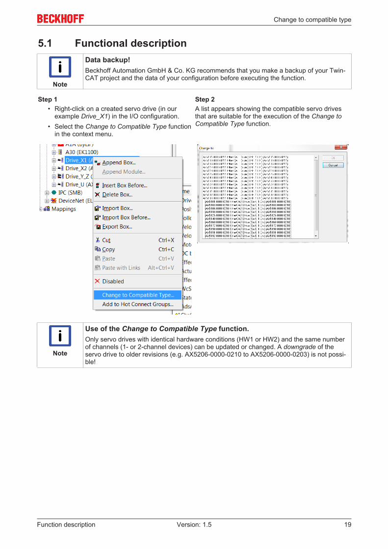
5.1 Functional description
Note
Data backup!Beckhoff Automation GmbH & Co. KG recommends that you make a backup of your Twin-CAT project and the data of your configuration before executing the function.
Step 1 Step 2• Right-click on a created servo drive (in our
example Drive_X1) in the I/O configuration.• Select the Change to Compatible Type function
in the context menu.
A list appears showing the compatible servo drivesthat are suitable for the execution of the Change toCompatible Type function.
Note
Use of the Change to Compatible Type function.Only servo drives with identical hardware conditions (HW1 or HW2) and the same numberof channels (1- or 2-channel devices) can be updated or changed. A downgrade of theservo drive to older revisions (e.g. AX5206-0000-0210 to AX5206-0000-0203) is not possi-ble!

Change to compatible type
Function description20 Version: 1.5
Step 3 Step 4• Select a suitable servo drive from the list (Step
2).• Confirm with "OK".• In the next step, start the function by left-
clicking on "OK".
The following settings are now changed for theselected servo drive in the TC Drive Manager:
• EtherCAT \ Slave \ Info: Physical device, product code, revision number,serial number, type.
• Settings / StateMachine:CheckRevisionNo (if changed)
• ProcessData:The missing Sync Manager is added (ifavailable).
Once steps 1 – 4 have been completed, the changes are adopted into the startup list in parameterP-0-0010. These are then compared with the Beckhoff-AX5xxx.xml defined standard configurations.
Note
Aborting and restarting the function!It is possible at all times to stop and restart the function.
• To stop the function: Click on Cancel in step 3. The procedure is now aborted.
• To restart the function: First of all, make a backup of your data. Then begin with step 1 of this functional de-scription.

Change to compatible type
Function description 21Version: 1.5
5.2 Term definitionsOrder key
The order key identifies the product. It is attached to the type plate on the outside and consists of a 14-character combination of letters and numbers.
Note
Further information about the order key can be found in the: AX5000 – system manual under product identification!
In the case of the AX5000 servo drives, Beckhoff makes a distinction between HardWare 1 and HardWare 2devices.
Firmware (version):
The firmware is the software of the AX5000 servo drive. This is identified accordingly with Firmware - v1.xxor Firmware - v2.xx. An allocation of the firmware revisions to the hardware versions of the device can befound in the chapter: Change to Compatible Type [} 17]“.
Revision No.: / Interface version ≠ order key
Each firmware has an allocated revision no. or interface version. This is saved on the E²Prom of the AX5000servo drive and can be read via the TwinCAT System Manager. The revision no. is shown in the last 8characters of the product / revision: e.g. AX5106-0000-0203
The first 4 characters are always zero.
Builds:
As soon as a firmware is released it is given a version number (V) and a build (b). If changes or optimizationstake place within a firmware version, the builds are incremented. Each firmware has a latest current version.
ESI – Device - Description:
An EtherCAT Slave Information is a device description in *xml format. It is required in order to carry outonline or offline configurations in TwinCAT. ESI files can be requested by manufacturers and are providedfor download.
There may be several ESI device descriptions in one *xml file.
Note
Structure of the ESI file in the *xml format:*xsd is a format that describes the structure of a device description (ESI) in the *xml file. Ifthe EtherCAT slave information is updated, the *xsd and *xml files should always be up-dated as well. This way you can ensure that the required information from the device de-scription is transferred fully.

Digital inputs and outputs
Function description22 Version: 1.5
6 Digital inputs and outputsThe AX5000 servo drive can be used to activate various functions via digital inputs and outputs. Thefunctions are assigned via eight inputs (0-7); input 7 can be configured as output. The individual functionsare described in this chapter.
Note
Reference values for the digital inputs and outputs:P-0-0251; P-0-0315; P-0-0400; P-0-0401; P-0-0402; P-0-0800
Overview of inputs and outputs with assignable functionsIn the „Digital I/O status“ section (1), the TC3 DriveManager provides an overview of all inputs andoutputs at the AX5000 servo drive. Inputs at which novoltage is present (low) are shown in red. Inputs atwhich voltage is present (high) are shown in signalgreen.The „ActFunction“ window (2) shows whether andwhere a function is active. The „Hardware enableconfiguration“ is assigned to input 2.The functions that can be assigned to the inputs andoutputs are shown in the „Digital I/O settings“ section(3). The functions listed under (3) are described laterin this chapter.
6.1 Diagnostic outputThe parameter P-0-0315 enables configuration of a diagnostic outputs at the AX5000 servo drive. For dual-channel devices this parameter is configurable for both channels (A and B).
Configuration
Default value: 0 No output
0: No outputNo diagnostic output function is selected.
1: High activeA diagnostic output function is selected.
Output number
Default value: 0 No
„Digital output 7“ can be configured as digital output with the func-tion „Diagnostic output“ under this setting in parameter P-0-0315.

Digital inputs and outputs
Function description 23Version: 1.5
Set output on Error (C1D)
Default value: 0 No
0: No The specified output (Digital output 7) does not respond to a C1Derror.
1: Yes The specified output (digital output 7) responds to a C1D error.
The error is displayed on the AX5000.
Set output on warning (C2D)
Default value: 0 No
0: No The specified output (digital output 7) does not respond to a C2Dwarning.
1: Yes The specified output (digital output 7) responds to a C2D warning.
The error is displayed on the AX5000.
6.2 Hardware-EnableA hardware enable for the AX5000 servo drive can be configured in the TC3 Drive Manager. This function is active in addition to thesoftware enable from the controller via the bus system. The two functions are connected via an AND link. The settings for this inputfunction are made in parameter P-0-0400.
Configuration
0: No hardware enable No hardware enable function is selected.1: High activeA hardware enable function is selected.
Default value: 0 No hardware enable
Input number
Under this setting in parameter P-0-0400 you can specify whichdigital input is to be configured with the function „Hardware en-able“. You can assign the function to one of eight digital inputs(0-7).
Default value: 0 Digital input 0
Disable reaction
Default value: 0 Torque off
0: Torque off The servo drive de-energizes the axis.1: Slow down according to P-x-0356(only asynchronous motors)The servo drive brakes the axis with the deceleration ramp set inparameter P-x-0356 (rotor slow down procedure parameter). 2: Emergency rampThe servo drive brakes the axis with the deceleration ramp set inparameter S-0-0429 (emergency stop deceleration).3: Halt rampThe servo drive brakes the axis with the deceleration ramp set inparameter S-0-0372 (drive halt acceleration bipolar)

Digital inputs and outputs
Function description24 Version: 1.5
Diagnostics
Default value: 0 Error
0: Error If axis control is active (enabled) and the hardware enable input isswitched off, the AX5000 servo drive reports error message F102(loss of the hardware enable).3: SilentIf axis control is active (enabled) and the hardware enable input isswitched off, the AX5000 servo drive reports no error.
6.3 Limit switch monitoring
DANGER
Serious injuries caused by moving axes!The limit switch monitoring in the AX5000 servo drive is purely functional and not suitablefor personal protection!Notwithstanding active limit switch monitoring a fault in the drive system may:- disable the protection functions of the limit switch- prevent braking of the axes through EStop and axis stop ramps.In other words, the axes may not respond. This could cause serious injury.Before commissioning ensure that all external personal protection measures were applied.
The parameter P-0-0401 enables configuration of two limit switches per axis. For dual-channel devices thisparameter is configurable for both channels (A and B).
Configuration
Default value: 0 No limit switch
0: No limit switchNo limit switch is configured / available.1: Normally closed (wire-break protection)The limit switch is closed if it was not reached by the axis.2: Normally openThe limit switch is open if it was reached by the axis.
Limit switch reaction
Default value: 0 E-Stop with a C1D error
0: E-Stop with a C1D errorBraking of the axis with the emergency stop ramp (P-0-0429) andtriggering of an error message (FCD0, FCD1). The error is dis-played on the AX5000.1: E-Stop with a C2D warningBraking of the axis with the emergency stop ramp (P-0-0429) andtriggering of a warning (ECD0, ECD1). The error is displayed onthe AX5000.2: Axis halt with a C2D warningBraking of the axis with the halt ramp (P-0-0372) and triggering ofan error message (FCD0, FCD1). The error is displayed on theAX5000.

Digital inputs and outputs
Function description 25Version: 1.5
Input number
Under this setting in parameter P-0-0401 you can specify whichdigital input is to be configured with the function „Position limitswitch“. You can assign the function to one of eight digital inputs(0-7).
Note
Configuration of the positive and negative limit switchThe positive and negative limit switch can be configured in parameter P-0-0401. The se-lectable settings are identical for both limit switch versions and are described in this chapterfor the positive limit switch only.
6.4 Ready to operateIn the AX5000 configuration this device can beintegrated in the ready-chain of the machine. Thisfunction requires a digital input and a digital output.Activation of this function and allocation to therespective input and output is realized in parameterP-0-0402. Since only digital input no. 7 can optionallybe configured as output, only digital output no. 7 isoffered as output number.
6.5 Digital output control word
Default value: 0 no output
Digital output 7 can be configured as „user output“ atthe AX5000 servo drive for signal output from thePLC.1: user output (P-0-0802)Digital output 7 can be controlled via parameterP-0-0802.The parameter P-0-0802 (3) can now be mapped inthe MasterDataTelegram (1) process data of theAX5000 servo drive and linked to a PLC variable.Proceed as follows:
• Adding parameters from „Available parametersfor process data“ to the „Parameters forprocess data“ via the button (2).
Bit 7 of this variable controls the state of digital output7.

Comissioning a Generic Encoder with BISS-C Interface
Function description26 Version: 1.5
7 Comissioning a Generic Encoder with BISS-CInterface
7.1 PrefaceBISS-C is an open standard for communication with a rotary or linear feedback device and is used byvarious encoder manufacturers.
The AX5000 does support this interface in general. Due to the many possible variations we now offer ageneric encoder XML file for rotary encoders and for linear encoders that can be used and adjusted to manydifferent encoders with BISS C interface.
Please use firmware version ≥ 2.06 build 27 or ≥ 2.10 build 14.
The following instructions explain the different settings.
7.2 Encoder-InterfaceIf the encoder provides a digital (BISS-C) interface AND an analogue Sine/Cosine interface, it must beconnected to X11/ X21 of the AX5000.
If the encoder provides digital (BISS-C) signals only, the option card AX572x is required and the encodermust be connected to X41/ X42.
Note
Please note:• Default clock frequency for the pure digital BISS-C interface is 5MHz. If you want to use
a digital encoder that requires lower clock frequencies, there are certain restrictions.Please see below chapter "Restrictions for Clock Frequency" for details.
• X11/ X21 will output more clock edges than necessary to read the position telegram.With some encoders this will cause problems.

Comissioning a Generic Encoder with BISS-C Interface
Function description 27Version: 1.5
7.3 WiringCorrect wiring, of course, is essential to run any feedback device correctly. Depending on wether or not thereare sense lines for the power supply there are 2 or 4 wires for the supply voltage:
Signal DescriptionAX5000 EncoderUs_5V +5V Power SupplyGND_5V GND for the +5V Power SupplyUs_5V Sense +5V Sensor connection (optional)GND_Sense 0V Sensor connection (optional)
For the position infomation there are the following signals. Incremental Sine/ Cosine signals are not providedby every encoder.
Signal DescriptionAX5000 EncoderDX + (Data) Data +, (also "SLO +")DX – (Data) Data -, (also "SLO -")CLK + (Clock) Clock signal, (also "MA +")CLK – (Clock) Clock signal, (also "MA -")SIN + (optional) Sine +REFSIN (optional) Sine -COS + (optional) Cosine +REFCOS (optional) Cosine -
Please refer to the AX5000 "Startup Manual" or "System Manual" for correct wiring!
7.4 Required Data for ComissioningBefore you start commissioning the encoder, make sure you do have the following information about it:
Encoder feature Example1 What power supply does the encoder need? In case it is 5 V:
Does it provide connections for the sense line?5 V with sense line
2 Maximum current consumption of the encoder? The AX5000 canprovide a max. of 250 mA per feedback channel.
150 mA
3 Pure digital interface or sine/ cosine signals provided? with sine/ cosine signals4 Maximum clock frequency for the BISS-C communication 10 MHz5 For a rotary encoder: Number of singleturn bits and number of
multiturn bitsFor a linear encoder: Number of position bits
rotary, 19 bits ST, 12 bits MT
6 For a rotary encoder: Number of sine periods per revolutionFor a linear encoder: Length of signal period
rotary: 2048
7 For a linear encoder: Resolution of the digital interface
Screenshots in the following explanation show the configuration for the above example.
Comissioning a Generic Encoder with BISS-C Interface
Function description28 Version: 1.5
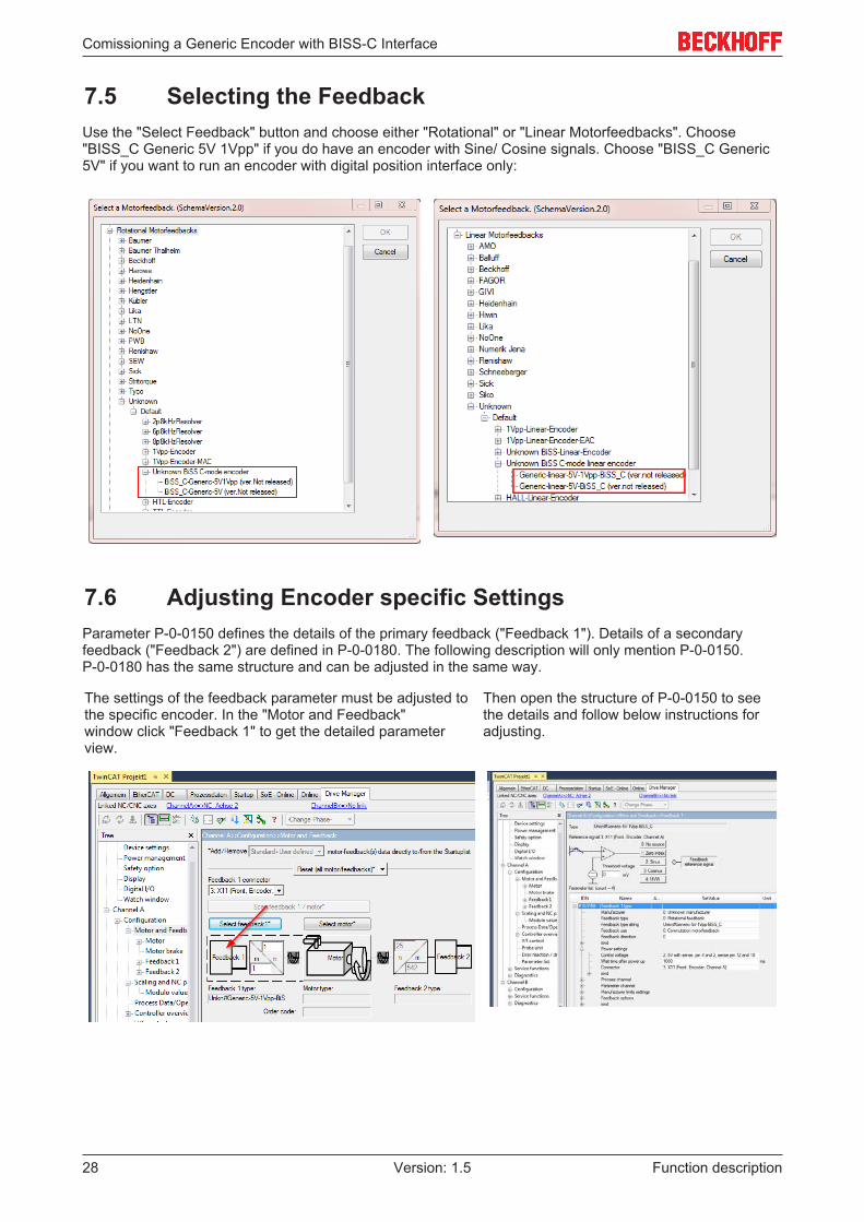
7.5 Selecting the FeedbackUse the "Select Feedback" button and choose either "Rotational" or "Linear Motorfeedbacks". Choose"BISS_C Generic 5V 1Vpp" if you do have an encoder with Sine/ Cosine signals. Choose "BISS_C Generic5V" if you want to run an encoder with digital position interface only:
7.6 Adjusting Encoder specific SettingsParameter P-0-0150 defines the details of the primary feedback ("Feedback 1"). Details of a secondaryfeedback ("Feedback 2") are defined in P-0-0180. The following description will only mention P-0-0150.P-0-0180 has the same structure and can be adjusted in the same way.
The settings of the feedback parameter must be adjusted tothe specific encoder. In the "Motor and Feedback"window click "Feedback 1" to get the detailed parameterview.
Then open the structure of P-0-0150 to seethe details and follow below instructions foradjusting.

Comissioning a Generic Encoder with BISS-C Interface
Function description 29Version: 1.5
7.7 Definition of Parameter P-0-0150
7.7.1 Feedback Type stringThe name of the encoder is not important for operation. It may be changed to remember what encoder youare using:
7.7.2 Power SettingsPlease choose the correct power supply accoding to the datasheet of your encoder. Correct voltage and"sense" setting is essential.
"Wait time after power up" is a delay after switching the power supply on, before the AX5000 startscommunicating with the encoder. If you do not know the correct value, keep the default.The "Connector" should be correct if the correct encoder has been chosen. If not, please correct!
Comissioning a Generic Encoder with BISS-C Interface
Function description30 Version: 1.5
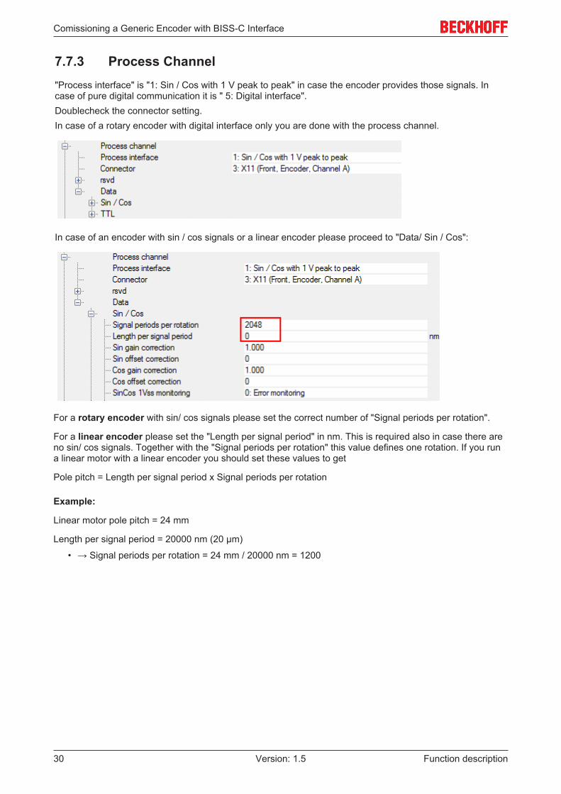
7.7.3 Process Channel"Process interface" is "1: Sin / Cos with 1 V peak to peak" in case the encoder provides those signals. Incase of pure digital communication it is " 5: Digital interface".Doublecheck the connector setting.In case of a rotary encoder with digital interface only you are done with the process channel.
In case of an encoder with sin / cos signals or a linear encoder please proceed to "Data/ Sin / Cos":
For a rotary encoder with sin/ cos signals please set the correct number of "Signal periods per rotation".
For a linear encoder please set the "Length per signal period" in nm. This is required also in case there areno sin/ cos signals. Together with the "Signal periods per rotation" this value defines one rotation. If you runa linear motor with a linear encoder you should set these values to get
Pole pitch = Length per signal period x Signal periods per rotation
Example:
Linear motor pole pitch = 24 mm
Length per signal period = 20000 nm (20 µm)
• → Signal periods per rotation = 24 mm / 20000 nm = 1200

Comissioning a Generic Encoder with BISS-C Interface
Function description 31Version: 1.5
7.7.4 Parameter Channel
Parameter ExplanationParameter interface 6: BISS C-Mode unidirectional (Do not change!)Connector Doublecheck where you connected the encoder.Identifier Not used, keep 0.Bit resolution singleturn position For a rotary encoder: Get number of singleturn bits
from encoder datasheet.For a linear encoder: Number of position bits.
Bit resolution multiturn position For rotary encoder: Get number of multiturn bitsfrom encoder datasheet.For a linear encoder: 16
Number of clockcycles to get singleturn position orabsolute position
Get from encoder datasheet (usually same value as"Bit resolution singleturn position").
Digital nameplate Keep "0: No digital namplate".Commutation mode Will be set later, when you do the motor
commissioningAdjustable commutation offset Keep 0.0Linear resolution about digital interface [nm] For rotary encoder: Keep 0
For linear encoder: Get the number from the encoderdatasheet (in nanometer).

Comissioning a Generic Encoder with BISS-C Interface
Function description32 Version: 1.5
7.7.5 Parameter Channel / Data / BISS
Most encoders will run with the preset default values.
Do not change any settings unless you are sure that your specific encoder requires that!
Some explanations (referring to the numbers in the picture):
1. The settings are the same for most common encoders and will be preset.2. Mcd (multi cycle data) is not used here. Keep values 0.3. Use "Min. clock speed" and "Max. clock speed "from encoder datasheet if available. If you need to
change this, see below chapter “Restrictions for Clock Frequency”.4. Register mode is not used. Keep settings as preset.5. Keep values 0 (except in some cases for “Pretrigger time encoder to sync” as described below).

Comissioning a Generic Encoder with BISS-C Interface
Function description 33Version: 1.5
7.8 Restrictions for Clock FrequencyFirmware ≥ v2.10 build 0015 allows setting different frequency values.
Note
Possible values of the clock frequency to be set: 2000, 2500, 3333, 5000[kHz].The clock frequency can be changed in the parameter P-0-0150 under:Parameter channel → Data → BISS → Sensor mode: Max. clock speed
If other values are set, the software will use the next possible lower value. Lower clock frequency causeslonger data transmission time.
Communication signals between AX5000 and encoder look like this:
During the "Ack" period the encoder prepares for transferring the actual position value. With the rising edgeat "Start" it signals to be ready and then starts transferring data.
Due to its internal cycles the AX5000 needs the position at certain point of time after it has started reading.This means the time from the first rising edge of the clock signal to the last CRC bit must not exceed 18µs.
Example:
Clock frequency: 3.333 MHz => Bit time = 1/ 3.333MHz = 0.3 µs
Number of bits to be transferred for a position telegram:
Example 1 Example 24 µs 8 µs Preparing time of encoder ("Ack")Number of bits1 1 Start1 1 CDS (Cyclic data slave, not used,
always 0)26 32 Position1 1 Error (status)1 1 Warning (status)6 6 CRC1 1 Stop/ Timeout37 43 Number of clock cycles for
complete telegram

Comissioning a Generic Encoder with BISS-C Interface
Function description34 Version: 1.5
Example 1 Example 2Transmission time = 4 µs + 37 x 0.3 µs = 15.1 µs <18 µs
Transmission time = 8 µs + 43 x 0.3 µs = 20.9 µs >18 µs
◦ The encoder in this example can berun at 3.333 MHz clock frequency.
◦ For this case it is possible to set avalue for "Pretrigger time encoder tosync" to start reading of the encoderearlier in the cycle:
20.9 µs - 18 µs = 2.9 µs◦ Set "Pretrigger time encoder to sync" =
4µs (1µs margin).
Note
The value for the pretrigger must not exceed 15 µs!
7.9 TroubleshootingMost errors in this context are caused by wrong wiring. Please double check that if you get any feedbackerrors! To find out more details you may try one or more of the following steps.

Comissioning a Generic Encoder with BISS-C Interface
Function description 35Version: 1.5
7.9.1 Try analog signals onlyIf you do have an encoder with BISS C interface and analogue signals you may choose a setup withoutusing the digital interface. Choose "Unknown/ 1Vpp..." with the correct sense settings and resolution.
If you get errors related to the sense line (e.g. F705, F707, F879,...), please double check the wiring of thesense lines or choose a setting without sense line ("5Vfixed"). If you do not get erros related to the powersupply but to the signal amplitude, check wiring of the sine/ cosine signals. If possible you may use ahardware oscilloscope to look at the signals.
Note
If the AX5000 senses a feedback error it switches the encoder power supplyoff!
When you get correct 1Vpp signals, i.e. no error related to that, you may double check the resolution: Doesthe position count one revolution when you turn the encoder one rev.? Dou you see the correct distancewhen you move the linear encoder?
7.9.2 Change BISS settingsIf the analogue signals do not cause an error or there are no analogue signals, but you get feedback errorsrelated to the digital signals (e.g. F717, F718, F72x,...) please doublecheck the wiring and the number ofposition bits.
If you are not sure about that number you may try changing values for "Bit resolution singleturn position" and"Number of clockcycles to get singleturn position".

Internal velocity filters
Function description36 Version: 1.5
8 Internal velocity filters
WARNING
Warning, risk of injury from uncontrolled movements!When working with the described filters there is always a danger of the motor performinguncontrolled movements due to impermissible parameterization. Make sure that your appli-cation allows these movements and secure the entire danger zone against inadvertent en-try; ensure that no persons are in the danger zone.
Note
Application of the Velocity Observer!Above a frequency of 300 Hz noise can become problematic. First and second-order filtersare often ineffective in this case. The Velocity Observer of the AX5000 servo drive providesthe velocity controller with a speed signal available without resonance-induced oscillationsover the widest possible frequency range. It is available in FW v2.06 in Basic mode (thirdorder) and in FW v2.10 in Advanced mode (fifth order).Further information can be found in chapter: „Velocity Observer“ of this function manual.
The control quality describes the capacity of the drive system to follow the setpoint values highlydynamically, with low losses and fail-safe. The control quality depends on many factors. On the mechanicalside these could be soft drive trains with belt drive, or resonance points caused by the natural ageing ofcomponents or special features of the mechanical structure. Without the use of filters the only possibility is toreduce the loop gain and to adapt it to the worst condition. However, this adaptation affects the totalapplication and lowers the dynamics of the drive system. The application and the parameterization of theinternal speed and current filters act, for example, specifically on a resonant frequency, hence allowing ahigh loop gain and thus a highly dynamic drive system. The filters described here serve to eliminate orattenuate unwanted noise or resonant frequencies. The main control loops of a servo drive are the positioncontroller, the velocity controller and the current controller. With the exception of the position controller,software filters can be inserted before the controllers. The characteristic of these special software filters isrealized by means of a 1st and 2nd order IIR filter with time-discrete transfer function.
8.1 Basic principlesThe drive system receives the input parameter "Speed n = 40 rpm" from the PLC. If the drive system isoperating under optimum conditions, the motor achieves this speed with very good control quality. Thedifferent characteristics of the drive system also cause sources of resonance among other things, which arealways disturbing. They often manifest themselves in oscillating shafts or hum frequencies. Overlaid signaloscillations of the encoder systems can similarly create high frequency noise, thus reducing the controlquality.
The following test provides information about possibly existing interference frequencies: Drive through thenecessary operating speed range and make a scope recording of the actual active current (IDN S-0-0084).On the basis of the curve of the graph you can judge whether or not there are points of interference.

Internal velocity filters
Function description 37Version: 1.5
8.2 1st and 2nd order IIR filter – Infinite Impulse ResponseFilter
A general digital filter with time-discrete transfer function has been implemented for the current commandvalue filter.
The following filters can be selected in the TCDriveManager:
• Notch filter• Phase correction filter 1st order (PD T1 or lead lag)• Low-pass filter 1st order (PT1)• Phase correction filter 2nd order (Bi Quad)• Low-pass filter 2nd order (PT2)
The coefficients b0, b1, b2, and a1, a2 determine the characteristic of all the filters described and can also bedirectly specified.
8.3 Notch filter (band-stop filter)The notch filter is designed as a narrow-band filter forthe attenuation of resonance frequencies. Select aservo drive (1) in the TwinCAT System Manager,start the TCDriveManager (2), click on the respectiveaxis (3) and select the "Current command valuefilter" (4).A maximum of four filters are evaluated, which can beparameterised independently of one another. In area(6), activate the filter that you would like to occupywith the notch filter. The cycle time of the velocitycontroller is indicated in field (7). The "QMathFactor" (8) determines the scaling of the filter inputparameter. With the current filter implementation themaximum possible resolution is achieved with thedefault value "30".Now select "Notch filter" (5) from the drop-downmenu.

Internal velocity filters
Function description38 Version: 1.5
8.3.1 Parameterisation of the filter
WARNING
Warning, risk of injury from uncontrolled movements!Impermissible attenuation values lead to a strong phase shift, which can result in uncon-trolled acceleration of the motor and other instable states.
There are two different methods of parameterising the filter.
"Classic" method
This variant is activated by checking the "Classic"checkbox (9).The parameters "Depth" (10), "Bandwidth" (11) and"Frequency" (12) must now be determined andentered; see the diagram "Bode Plot" below for this.The parameters entered lead internally to thecalculation of the coefficients b0, b1, b2, and a1, a2(see the above diagram "1st and 2nd order IIR filter" forthis).Click on the "Download" button (13) to conclude theparameterisation. If you are online these parametersare loaded directly into the AX5000 and activated. Ifyou are offline they are only written into the start-uplist.
"Classic" method – step by step
The "Step by step" extension enables you tocalculate and enter the coefficients b0, b1, b2, and a1,a2 yourself (see the above diagram "1st and 2nd orderIIR filter"). Among other things you can now comparethe values calculated by the software with your ownvalues and see how changing the parameters affectsthe coefficients.The "Step by step" extension is activated by checkingthe "Step by step" checkbox (14). You can now enterthe parameters (10) to (12) as described in theprevious section, after which you click on the button(15). Subsequently, you can read off the calculatedcoefficients in area (16). If you wish to accept thesecoefficients, click on the button (17); they are nowentered automatically into area (18).Alternatively you can also determine the coefficientsyourself and enter them in area (18).If you finally click on the "Download" button (19), thevalues are always taken from area (18). If you areonline these parameters are loaded directly into theAX5000 and activated. If you are offline they are onlywritten into the start-up list. The calculated valuesfrom area (16) and the parameters (10) to (12)remain visible for information purposes.

Internal velocity filters
Function description 39Version: 1.5
"Low-pass and high-pass filter" method
This variant is activated by unchecking the "Classic"checkbox (22).You must now determine and enter the parameters"Low pass filter damping" (23), "Low pass filterfrequency" (24), "High pass filter damping" (26) and"High pass filter frequency" (27); the "Filter time" (25)is calculated by the software in relation to the "Lowpass filter frequency" (24). If you wish to emulate theclassic method, you must enter the centre frequencyplus half the bandwidth in field (24) and the centrefrequency minus half the bandwidth in field (27). Thedepth (10) is determined with the damping (23) or(26); see the diagram "Bode Plot" below for this. Theparameters entered lead internally to the calculationof the coefficients b0, b1, b2, and a1, a2 (see the abovediagram "1st and 2nd order IIR filter" for this).Using the methods described you can also map anyunbalances of the notch filter, among other things.Click on the "Download" button (28) to conclude theparameterisation. If you are online these parametersare loaded directly into the AX5000 and activated. Ifyou are offline they are only written into the start-uplist.
"Low-pass and high-pass filter" method – step by step
Note
Expert hint!The software calculates the coefficients independently using the parameters entered. If youhave sufficient experience in control technology you can also determine the coefficientsyourself and thus affect the behaviour of the filter.
The method is the same as in the "Classic method" – step by step.
Bode Plot

Internal velocity filters
Function description40 Version: 1.5
8.4 1st order low pass filterThe 1st order low pass filter attenuates all frequenciesabove the specified limit frequency. Select a servodrive (1) in the TwinCAT System Manager, start theTCDriveManager (2), click on the respective axis (3)and select the "Current command value filter" (4).A maximum of four filters are evaluated, which can beparameterised independently of one another. In area(6), activate the filter that you would like to occupywith the low pass filter. The cycle time of the velocitycontroller is indicated in field (7). The "QMathFactor" (8) determines the scaling of the filter inputparameter. With the current filter implementation themaximum possible resolution is achieved with thedefault value "30".Now select "Low pass filter 1. order" (29) from thedrop down menu.
8.4.1 Parameterisation of the filter
WARNING
Warning, risk of injury from uncontrolled movements!Impermissible damping values lead to a strong phase shift, which can result in uncontrolledacceleration of the motor and other instable states.
This filter is parameterised with the parameter "Limit frequency" (30). The time constant (31) is calculatedfrom the limit frequency according to the following equation"Time constant [s] = 1 / (2*Pi*Limit frequency [Hz] )".
Determination of the limit frequencyThe following test provides information about possibly existing interference frequencies: Drive through thenecessary operating speed range and make a scope recording of the actual active current (IDN S-0-0084). Afrequency analysis shows possibly existing resonance points.
Note
Phase shiftWith this filter you have no influence on the damping and any resulting phase shift. If youare not sure whether a phase shift is permissible, please use the "Phase correction filter 1.order"
Click on the "Download" button (32) to conclude theparameterisation. If you are online these parametersare loaded directly into the AX5000 and activated. Ifyou are offline they are only written into the start-uplist.

Internal velocity filters
Function description 41Version: 1.5
Example:
With this example the frequency response of the PT1filters has been illustrated for clarity. The Bode plot(logarithmic frequency curve) shows the amplitudeover frequency in the upper area and the associatedphase shift over frequency in the lower area. Seentogether, it is recognisable that a phase shift resultsfrom the damping of the amplitude.Parameter inputs in the TCDriveManager:Limit frequency = 6280 Hz(Time constant = 0.025343)
"1st order low pass filter" – method – "step by step"
Note
Expert hint!The software calculates the coefficients independently using the parameters entered. If youhave sufficient experience in control technology you can also determine the coefficientsyourself and thus affect the behaviour of the filter.
The method is the same as in the "Notch filter classic method" – "step by step".
8.5 1st order phase correction filterThe 1st order phase correction filter attenuates allfrequencies above the limit frequency entered. Selecta servo drive (1) in the TwinCAT System Manager,start the TCDriveManager (2), click on the respectiveaxis (3) and select the "Current command valuefilter" (4).A maximum of four filters are evaluated, which can beparameterised independently of one another. In area(6), activate the filter that you would like to occupywith the phase correction filter. The cycle time of thevelocity controller is indicated in field (7). The "QMathFactor" (8) determines the scaling of the filter inputparameter. With the current filter implementation themaximum possible resolution is achieved with thedefault value "30".Now select "Phase correction filter 1. order" (33) fromthe drop down menu.

Internal velocity filters
Function description42 Version: 1.5
8.5.1 Parameterisation of the filter
WARNING
Warning, risk of injury from uncontrolled movements!Impermissible damping values lead to a strong phase shift, which can result in uncontrolledacceleration of the motor and other instable states.
This filter is parameterised with the parameters "Limitfrequency" (35) and "Damping" (34). The timeconstant (36) is calculated from the limit frequencyaccording to the following equation --> "Timeconstant [s] = 1/ (2*Pi*Limit frequency [Hz])".Determination of the limit frequencyThe following test provides information about possiblyexisting interference frequencies: Drive through thenecessary operating speed range and make a scoperecording of the actual active current (IDN S-0-0084).A frequency analysis shows possibly existingresonance points.Click on the "Download" button (37) to conclude theparameterisation. If you are online these parametersare loaded directly into the AX5000 and activated. Ifyou are offline they are only written into the start-uplist.The limitation of the damping of the amplitudeensures that the phase shift returns to zero. Thelimited damping is adequate for most driveapplications.
Example:
With this example the frequency response of the PT1filters has been illustrated for clarity. The Bode plot(logarithmic frequency curve) shows the amplitudeover frequency in the upper area and the associatedphase shift over frequency in the lower area. Seentogether, it is recognisable that a phase shift resultsfrom the damping of the amplitude.Parameter inputs in the TCDriveManager:Time constant = 0.000025 s(Limit frequency = 6280 Hz)Damping:d0 = 0d1 = 0.05d3 = 0.15d4 = 0.35
"Phase correction filter 1. order" – method – "step by step"
Note
Expert hint!The software calculates the coefficients independently using the parameters entered. If youhave sufficient experience in control technology you can also determine the coefficientsyourself and thus affect the behaviour of the filter.
The method is the same as in the "Notch filter classic method" – "step by step".

I*t calculation in the AX5000 servo drive
Function description 43Version: 1.5
9 I*t calculation in the AX5000 servo drive
Note
Reference variables for the I*t calculation:P-0-0052; P-0-0090; P-0-0091; P-0-0092; P-0-0093
The I*t calculation serves as a safety function in the AX5000 servo drive. The max. permissible overcurrenttime area (I*tmax ) depends on the size of the devices. The servo drive may exceed the rated current for thecalculated time tmax. The value is then limited to the rated current on expiry of tmax.
In earlier firmware revisions the max. permissible overcurrent time area could not be used fully. Fromfirmware v2.06 (build 18) the complete overcurrent time area of the servo drive is now available.
This depends on the peak and rated currents of the different device sizes:
Longer exceedance of the rated current is possible by reducing the peak current. The time (tmax) is set inparameter P-0-0052.
Therefore, the following applies to the calculation of the parameter P-0-0052max:
The parameters involved are listed in the table below:
P-0-0052 Time limitation for peak current Settable value range: 0 – 65535 msP-0-0090 Channel peak current Dependent on the sizeP-0-0091 Channel rated current Dependent on the sizeP-0-0092 Configured channel peak current Dependent on the applicationP-0-0093 Configured channel rated current Dependent on the applicationtmax Max. time for Ipeak Dependent on the size1)*
1)*: 7 s for servo drives from the series AX52xx and AX5101 – AX5140.3 s for servo drives > AX5140 (see electrical data in the AX5000 system manual)
On changing status from Pre-Op to Op, the firmware in the AX5000 checks whether the value set inparameter P-0-0052 is permissible. A parameter error appears if the value is impermissible.
Special features of parameter P-0-0052:• P-0-0052 = 0
The current is always provided for the max. possible time (P-0-0052max) (max. 1000 s).• P-0-0052 < P-0-0052max
The current in parameter P-0-0092 is limited after the set time (1 ms - 65535 ms) to the value ofparameter P-0-0093.
If IAppl < P-0-0092, the current is available for a longer period and is limited after tAppl.

I*t calculation in the AX5000 servo drive
Function description44 Version: 1.5
9.1 Special features in the case of an AX520x two-channeldevice
• The overcurrent time area for the total current of the device is determined by the size.• By default, the same values for rated and peak current are available to both channels.
It is possible to increase the value of the rated current for one channel. It receives a larger portion of theovercurrent time area as a result. The remaining portion of the total current is then available to the secondchannel.
Calculation of the possible time (P-0-0052max):
Replace parameter P-0-0091 (Channel rated current) by parameter P-0-0093 (Configured channel current).
Calculation of the time at IAppl. < P-0-0092:
The following condition applies for P-0-0093max in the case of channel B:
I*t calculation in the AX5000 servo drive
Function description 45Version: 1.5
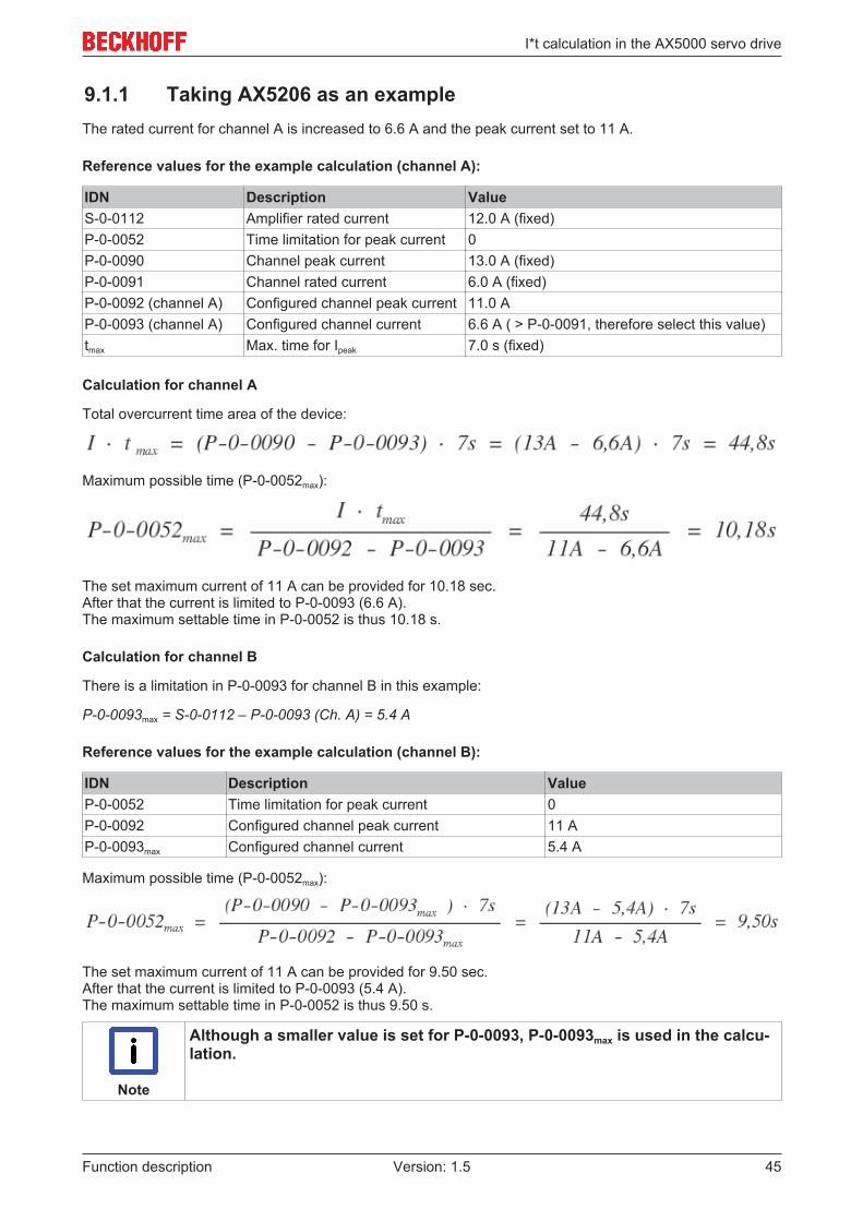
9.1.1 Taking AX5206 as an exampleThe rated current for channel A is increased to 6.6 A and the peak current set to 11 A.
Reference values for the example calculation (channel A):
IDN Description ValueS-0-0112 Amplifier rated current 12.0 A (fixed)P-0-0052 Time limitation for peak current 0P-0-0090 Channel peak current 13.0 A (fixed)P-0-0091 Channel rated current 6.0 A (fixed)P-0-0092 (channel A) Configured channel peak current 11.0 AP-0-0093 (channel A) Configured channel current 6.6 A ( > P-0-0091, therefore select this value)tmax Max. time for Ipeak 7.0 s (fixed)
Calculation for channel A
Total overcurrent time area of the device:
Maximum possible time (P-0-0052max):
The set maximum current of 11 A can be provided for 10.18 sec. After that the current is limited to P-0-0093 (6.6 A). The maximum settable time in P-0-0052 is thus 10.18 s.
Calculation for channel B
There is a limitation in P-0-0093 for channel B in this example:
P-0-0093max = S-0-0112 – P-0-0093 (Ch. A) = 5.4 A
Reference values for the example calculation (channel B):
IDN Description ValueP-0-0052 Time limitation for peak current 0P-0-0092 Configured channel peak current 11 AP-0-0093max Configured channel current 5.4 A
Maximum possible time (P-0-0052max):
The set maximum current of 11 A can be provided for 9.50 sec. After that the current is limited to P-0-0093 (5.4 A). The maximum settable time in P-0-0052 is thus 9.50 s.
Note
Although a smaller value is set for P-0-0093, P-0-0093max is used in the calcu-lation.
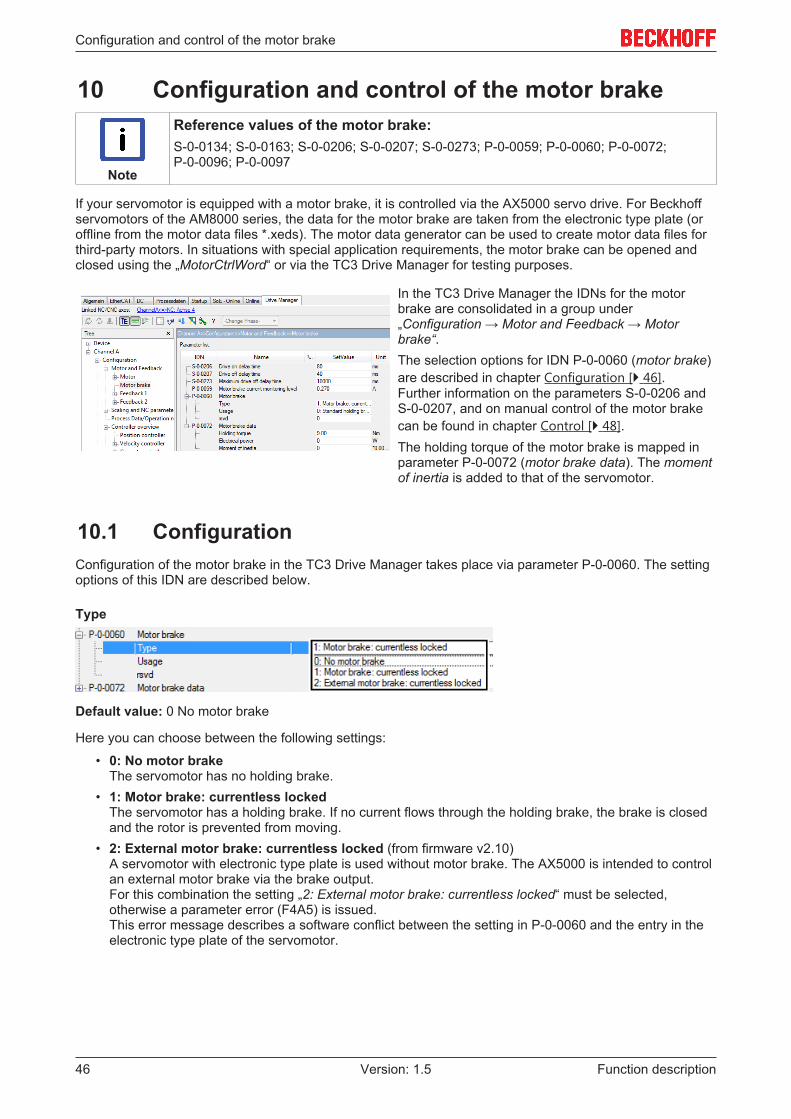
Configuration and control of the motor brake
Function description46 Version: 1.5
10 Configuration and control of the motor brake
Note
Reference values of the motor brake:S-0-0134; S-0-0163; S-0-0206; S-0-0207; S-0-0273; P-0-0059; P-0-0060; P-0-0072;P-0-0096; P-0-0097
If your servomotor is equipped with a motor brake, it is controlled via the AX5000 servo drive. For Beckhoffservomotors of the AM8000 series, the data for the motor brake are taken from the electronic type plate (oroffline from the motor data files *.xeds). The motor data generator can be used to create motor data files forthird-party motors. In situations with special application requirements, the motor brake can be opened andclosed using the „MotorCtrlWord“ or via the TC3 Drive Manager for testing purposes.
In the TC3 Drive Manager the IDNs for the motorbrake are consolidated in a group under„Configuration → Motor and Feedback → Motorbrake“.The selection options for IDN P-0-0060 (motor brake)are described in chapter Configuration [} 46].Further information on the parameters S-0-0206 andS-0-0207, and on manual control of the motor brakecan be found in chapter Control [} 48].The holding torque of the motor brake is mapped inparameter P-0-0072 (motor brake data). The momentof inertia is added to that of the servomotor.
10.1 ConfigurationConfiguration of the motor brake in the TC3 Drive Manager takes place via parameter P-0-0060. The settingoptions of this IDN are described below.
Type
Default value: 0 No motor brake
Here you can choose between the following settings:
• 0: No motor brakeThe servomotor has no holding brake.
• 1: Motor brake: currentless lockedThe servomotor has a holding brake. If no current flows through the holding brake, the brake is closedand the rotor is prevented from moving.
• 2: External motor brake: currentless locked (from firmware v2.10)A servomotor with electronic type plate is used without motor brake. The AX5000 is intended to controlan external motor brake via the brake output.For this combination the setting „2: External motor brake: currentless locked“ must be selected,otherwise a parameter error (F4A5) is issued.This error message describes a software conflict between the setting in P-0-0060 and the entry in theelectronic type plate of the servomotor.

Configuration and control of the motor brake
Function description 47Version: 1.5
Usage
Default value: 0 Standard holding brake
Here you can choose between the following settings:
• 0: Standard holding brakeThe default settings of the holding brake are used, based on which the holding brake only engages atstandstill.
• 1: Holding brake: Emergency brakeWhen an error message occurs at the AX5000 servo drive, the holding brake engages (independent ofstandstill monitoring S-0-0124). Therefore the holding brake also acts on rotating axes. This can lead toincreased wear and premature failure!
CAUTION
Risk of injury through falling or moving axes!As a rule, holding brakes in Beckhoff servomotors are not designed for service braking ofthe axes!Service braking causes increased wear of the holding brake!The service life would be reduced significantly. Increased wear leads to premature failure ofthe components.High risk of injury through axes that failed to stop! Particularly applications with verticalaxes can have a high risk potential.Check the different machine states and the brake control in different scenarios. If neces-sary, install an additional (safe) service brake.
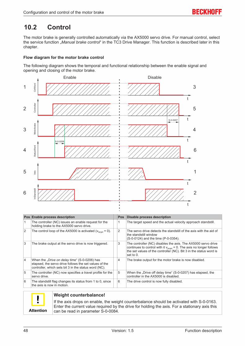
Configuration and control of the motor brake
Function description48 Version: 1.5
10.2 ControlThe motor brake is generally controlled automatically via the AX5000 servo drive. For manual control, selectthe service function „Manual brake control“ in the TC3 Drive Manager. This function is described later in thischapter.
Flow diagram for the motor brake control
The following diagram shows the temporal and functional relationship between the enable signal andopening and closing of the motor brake.
Pos Enable process description Pos Disable process description1 The controller (NC) issues an enable request for the
holding brake to the AX5000 servo drive.1 The target speed and the actual velocity approach standstill.
2 The control loop of the AX5000 is activated (vtarget = 0). 2 The servo drive detects the standstill of the axis with the aid ofthe standstill window(S-0-0124) and the time (P-0-0354).
3 The brake output at the servo drive is now triggered. 3 The controller (NC) disables the axis. The AX5000 servo drivecontinues to control with it vtarget = 0. The axis no longer followsthe set values of the controller (NC). Bit 3 in the status word isset to 0.
4 When the „Drive on delay time“ (S-0-0206) haselapsed, the servo drive follows the set values of thecontroller, which sets bit 3 in the status word (NC).
4 The brake output for the motor brake is now disabled.
5 The controller (NC) now specifies a travel profile for theservo drive.
5 When the „Drive off delay time“ (S-0-0207) has elapsed, thecontroller in the AX5000 is disabled.
6 The standstill flag changes its status from 1 to 0, sincethe axis is now in motion.
6 The drive control is now fully disabled.
Attention
Weight counterbalance!If the axis drops on enable, the weight counterbalance should be activated with S-0-0163.Enter the current value required by the drive for holding the axis. For a stationary axis thiscan be read in parameter S-0-0084.

Configuration and control of the motor brake
Function description 49Version: 1.5
Manual control of the motor brake for testing purposes
In order to use the service function of the TC3 Drive Manager for the motor brake, select it in the TC3 DriveManager under „Service functions → Manual brake control“.
Default settingThe default setting of the motor brake is „Automatic“.The enabled mode is displayed under„ActValue“ (current value). If it differs from yourselection, the text is shown in red.The current status of the motor brake is shown under„Motor brake status“. It can be „Locked“ or„Unlocked“.The status changes when a new start-up list isdownloaded.
„Force unlock“ optionThe motor brake is released via the command „Forceunlock“.Release the holding brake as follows:
• Activate Force unlock
• Press the Download button .
The change is activated via the „Download“ button. Itcontains your new settings.You have successfully released your motor brake.
Controlling the motor brake for special application requirements
The parameters P-0-0096 (motor control word) and P-0-0097 (motor status word) are available for situationswhere the motor brake has to be controlled from within the application. The following table shows thecommand sequence for unlocking and locking the brake from the PLC.
Release the brake Lock the brakeControl-Word (P-0-0096) Status-Word (P-0-0097) Control-Word (P-0-0096) Status-Word (P-0-0097)
0x0000 0x00000x0002 0x0001
0x0003 0x0000
The PLC block: FB_SoEAX5000SetMotorCtrlWord is available for simplified control of the motor brake.
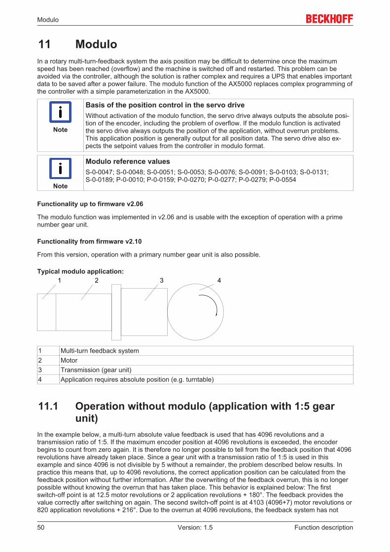
Modulo
Function description50 Version: 1.5
11 ModuloIn a rotary multi-turn-feedback system the axis position may be difficult to determine once the maximumspeed has been reached (overflow) and the machine is switched off and restarted. This problem can beavoided via the controller, although the solution is rather complex and requires a UPS that enables importantdata to be saved after a power failure. The modulo function of the AX5000 replaces complex programming ofthe controller with a simple parameterization in the AX5000.
Note
Basis of the position control in the servo driveWithout activation of the modulo function, the servo drive always outputs the absolute posi-tion of the encoder, including the problem of overflow. If the modulo function is activatedthe servo drive always outputs the position of the application, without overrun problems.This application position is generally output for all position data. The servo drive also ex-pects the setpoint values from the controller in modulo format.
Note
Modulo reference valuesS-0-0047; S-0-0048; S-0-0051; S-0-0053; S-0-0076; S-0-0091; S-0-0103; S-0-0131;S-0-0189; P-0-0010; P-0-0159; P-0-0270; P-0-0277; P-0-0279; P-0-0554
Functionality up to firmware v2.06
The modulo function was implemented in v2.06 and is usable with the exception of operation with a primenumber gear unit.
Functionality from firmware v2.10
From this version, operation with a primary number gear unit is also possible.
Typical modulo application:1 2 3 4
1 Multi-turn feedback system2 Motor3 Transmission (gear unit)4 Application requires absolute position (e.g. turntable)
11.1 Operation without modulo (application with 1:5 gearunit)
In the example below, a multi-turn absolute value feedback is used that has 4096 revolutions and atransmission ratio of 1:5. If the maximum encoder position at 4096 revolutions is exceeded, the encoderbegins to count from zero again. It is therefore no longer possible to tell from the feedback position that 4096revolutions have already taken place. Since a gear unit with a transmission ratio of 1:5 is used in thisexample and since 4096 is not divisible by 5 without a remainder, the problem described below results. Inpractice this means that, up to 4096 revolutions, the correct application position can be calculated from thefeedback position without further information. After the overwriting of the feedback overrun, this is no longerpossible without knowing the overrun that has taken place. This behavior is explained below: The firstswitch-off point is at 12.5 motor revolutions or 2 application revolutions + 180°. The feedback provides thevalue correctly after switching on again. The second switch-off point is at 4103 (4096+7) motor revolutions or820 application revolutions + 216°. Due to the overrun at 4096 revolutions, the feedback system has not

Modulo
Function description 51Version: 1.5
taken into account the revolution in the range (a) and displays 7 motor revolutions, but only 1 applicationrevolution + 144°; one motor revolution (72°) is missing. This problems occurs every 4096 motor revolutionsand keeps growing by one motor revolution. In order to be able to determine the correct application position,the overruns or the resulting position offset must be stored on the application side. This requirementnecessitates the use of the UPS mentioned at the start, so that this can be guaranteed even in the case of apower failure.
Note
Selecting the gear unit!If a gear unit with a transmission ratio of 2x is selected, the zero points of the motor revolu-tion and the overrun of the absolute value encoder coincide. The above behavior does notoccur.
11.2 Operation with moduloIn the case of operation with a modulo, the following properties are brought to bear:
1. The range of the multi-turn encoder is subdivided into four large rangesð Range of the multi-turn encoder = 4096 revolutionsð One quarter range = 1024 revolutions
2. Saving procedureð On each transition from one quarter range to another, the modulo data set is modified and saved in
the servo drive (real position and CRC)ð The servo drive always has two modulo data sets saved. These data sets are used in alternation.ð A modulo data set is also saved if the EtherCAT state changes from SaveOP to PreOP.
3. Power-on procedureð Both modulo data sets are read if the EtherCAT transition changes from Boot to Init. The last valid
data set is used to reconstruct the modulo position.4. Power supply error (uncontrolled voltage drop of the 24 V supply)
ð Under certain circumstances it may no longer be possible to save a data set because the 24 Vsupply has been interrupted. Because two data sets exist at all times, however, one of them is validand can be used to reconstruct the modulo position at the next power-on.
5. Maximum speed during operation with moduloð Since the saving of the modulo data sets in an internal persistent memory in the AX5000 cannot take
place at an infinitely fast speed, the motor speed is limited. An example of the calculation of themaximum possible speed can be found in the section Maximum possible speed [} 55].
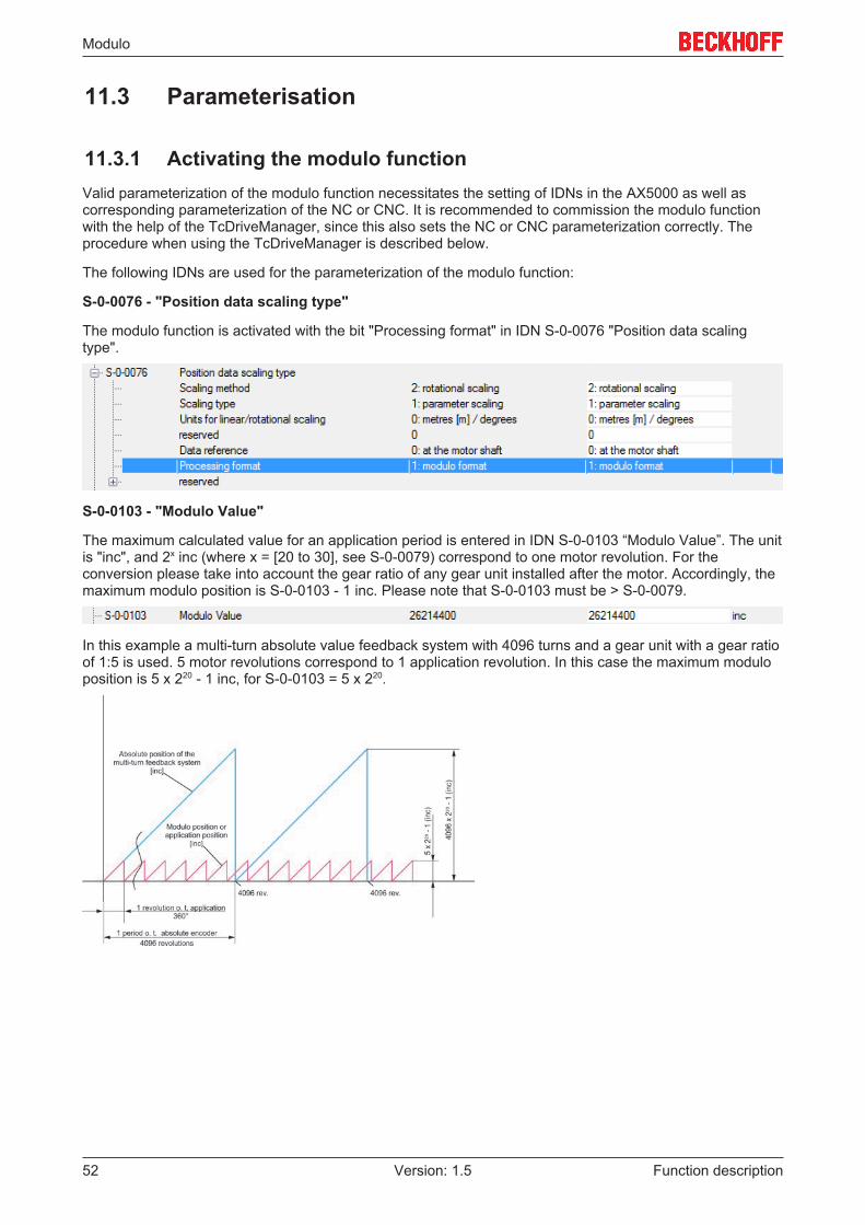
Modulo
Function description52 Version: 1.5
11.3 Parameterisation
11.3.1 Activating the modulo functionValid parameterization of the modulo function necessitates the setting of IDNs in the AX5000 as well ascorresponding parameterization of the NC or CNC. It is recommended to commission the modulo functionwith the help of the TcDriveManager, since this also sets the NC or CNC parameterization correctly. Theprocedure when using the TcDriveManager is described below.
The following IDNs are used for the parameterization of the modulo function:
S-0-0076 - "Position data scaling type"
The modulo function is activated with the bit "Processing format" in IDN S-0-0076 "Position data scalingtype".
S-0-0103 - "Modulo Value"
The maximum calculated value for an application period is entered in IDN S-0-0103 “Modulo Value”. The unitis "inc", and 2x inc (where x = [20 to 30], see S-0-0079) correspond to one motor revolution. For theconversion please take into account the gear ratio of any gear unit installed after the motor. Accordingly, themaximum modulo position is S-0-0103 - 1 inc. Please note that S-0-0103 must be > S-0-0079.
In this example a multi-turn absolute value feedback system with 4096 turns and a gear unit with a gear ratioof 1:5 is used. 5 motor revolutions correspond to 1 application revolution. In this case the maximum moduloposition is 5 x 220 - 1 inc, for S-0-0103 = 5 x 220.
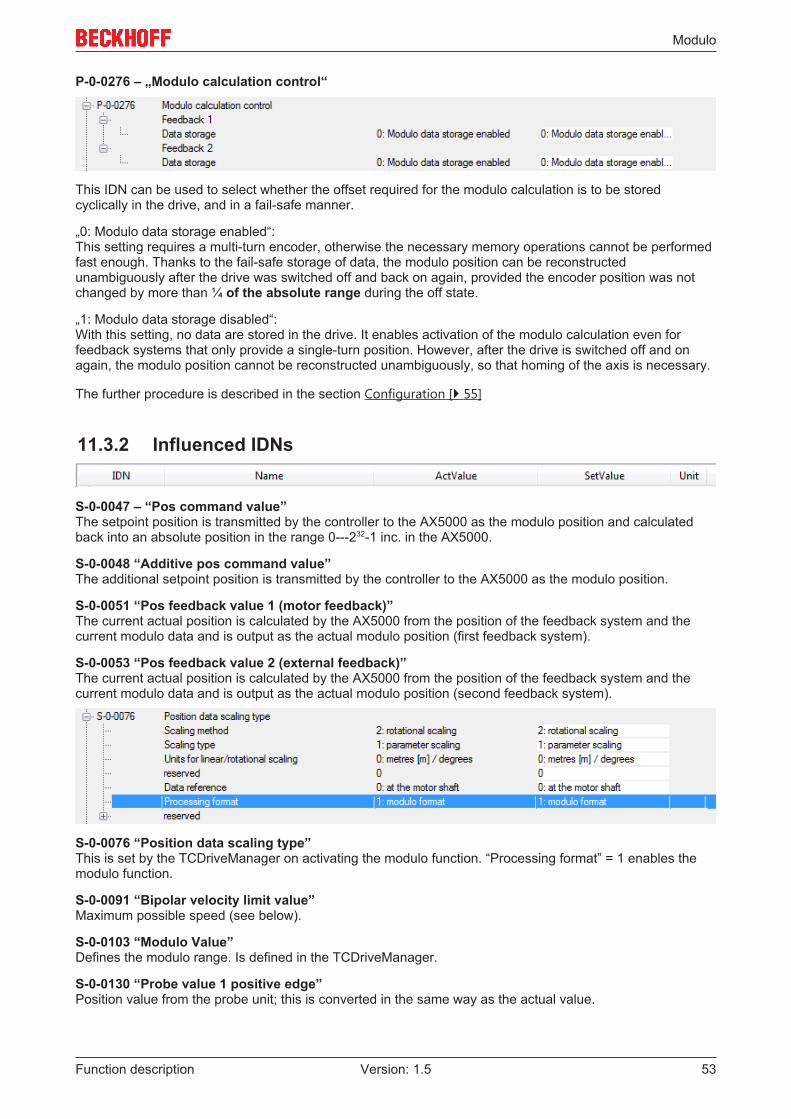
Modulo
Function description 53Version: 1.5
P-0-0276 – „Modulo calculation control“
This IDN can be used to select whether the offset required for the modulo calculation is to be storedcyclically in the drive, and in a fail-safe manner.
„0: Modulo data storage enabled“:This setting requires a multi-turn encoder, otherwise the necessary memory operations cannot be performedfast enough. Thanks to the fail-safe storage of data, the modulo position can be reconstructedunambiguously after the drive was switched off and back on again, provided the encoder position was notchanged by more than ¼ of the absolute range during the off state.
„1: Modulo data storage disabled“:With this setting, no data are stored in the drive. It enables activation of the modulo calculation even forfeedback systems that only provide a single-turn position. However, after the drive is switched off and onagain, the modulo position cannot be reconstructed unambiguously, so that homing of the axis is necessary.
The further procedure is described in the section Configuration [} 55]
11.3.2 Influenced IDNs
S-0-0047 – “Pos command value” The setpoint position is transmitted by the controller to the AX5000 as the modulo position and calculatedback into an absolute position in the range 0---232-1 inc. in the AX5000.
S-0-0048 “Additive pos command value”The additional setpoint position is transmitted by the controller to the AX5000 as the modulo position.
S-0-0051 “Pos feedback value 1 (motor feedback)”The current actual position is calculated by the AX5000 from the position of the feedback system and thecurrent modulo data and is output as the actual modulo position (first feedback system).
S-0-0053 “Pos feedback value 2 (external feedback)”The current actual position is calculated by the AX5000 from the position of the feedback system and thecurrent modulo data and is output as the actual modulo position (second feedback system).
S-0-0076 “Position data scaling type”This is set by the TCDriveManager on activating the modulo function. “Processing format” = 1 enables themodulo function.
S-0-0091 “Bipolar velocity limit value”Maximum possible speed (see below).
S-0-0103 “Modulo Value”Defines the modulo range. Is defined in the TCDriveManager.
S-0-0130 “Probe value 1 positive edge”Position value from the probe unit; this is converted in the same way as the actual value.
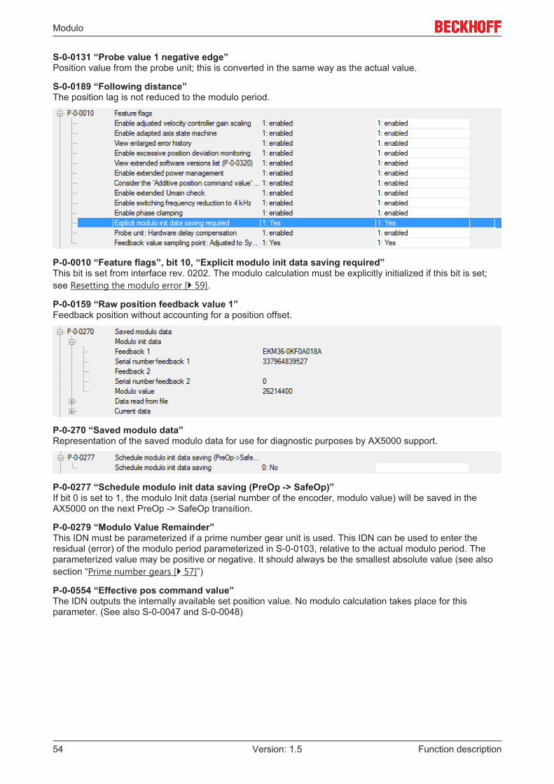
Modulo
Function description54 Version: 1.5
S-0-0131 “Probe value 1 negative edge”Position value from the probe unit; this is converted in the same way as the actual value.
S-0-0189 “Following distance”The position lag is not reduced to the modulo period.
P-0-0010 “Feature flags”, bit 10, “Explicit modulo init data saving required”This bit is set from interface rev. 0202. The modulo calculation must be explicitly initialized if this bit is set;see Resetting the modulo error [} 59].
P-0-0159 “Raw position feedback value 1”Feedback position without accounting for a position offset.
P-0-270 “Saved modulo data”Representation of the saved modulo data for use for diagnostic purposes by AX5000 support.
P-0-0277 “Schedule modulo init data saving (PreOp -> SafeOp)”If bit 0 is set to 1, the modulo Init data (serial number of the encoder, modulo value) will be saved in theAX5000 on the next PreOp -> SafeOp transition.
P-0-0279 “Modulo Value Remainder”This IDN must be parameterized if a prime number gear unit is used. This IDN can be used to enter theresidual (error) of the modulo period parameterized in S-0-0103, relative to the actual modulo period. Theparameterized value may be positive or negative. It should always be the smallest absolute value (see alsosection “Prime number gears [} 57]”)
P-0-0554 “Effective pos command value”The IDN outputs the internally available set position value. No modulo calculation takes place for thisparameter. (See also S-0-0047 and S-0-0048)
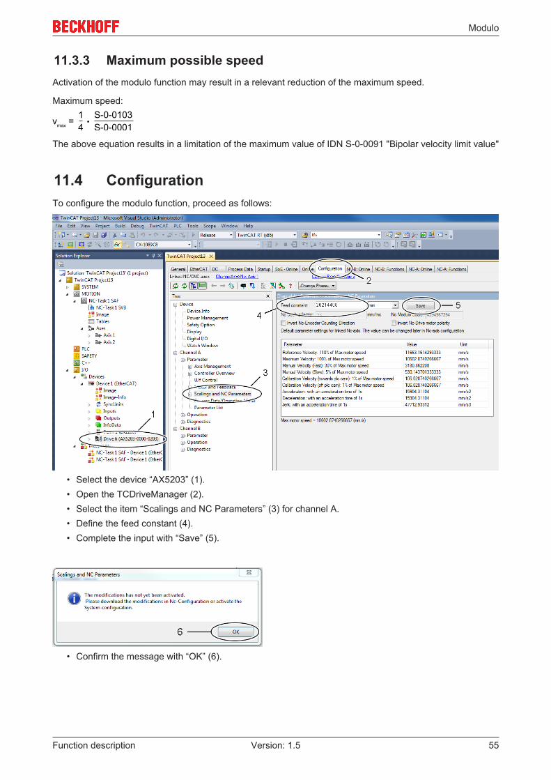
Modulo
Function description 55Version: 1.5
11.3.3 Maximum possible speedActivation of the modulo function may result in a relevant reduction of the maximum speed.
Maximum speed:
v =max
S-0-01031S-0-00014
The above equation results in a limitation of the maximum value of IDN S-0-0091 "Bipolar velocity limit value"
11.4 ConfigurationTo configure the modulo function, proceed as follows:
• Select the device “AX5203” (1).• Open the TCDriveManager (2).• Select the item “Scalings and NC Parameters” (3) for channel A.• Define the feed constant (4).• Complete the input with “Save” (5).
• Confirm the message with “OK” (6).

Modulo
Function description56 Version: 1.5
• Select the device “AX5203” (7).• Open the TCDriveManager (8).• Select the item “Modulo value” (9).• Define the modulo range in the preset unit (11).
The TcDriveManager subsequently calculates the modulo value in the unit increments (10).Complete the input with “Accept” (12).
• Confirm the message with “OK” (12).
• Repeat the procedure for the second channel (“Channel B”).• Activate the configuration.
• If no modulo data have been saved in the servo drive yet, error code F350 (“No saved data could beloaded”) appears on initialization; see also section Exchange [} 58].
• The reset functionality is described in section Resetting the modulo error [} 59].

Modulo
Function description 57Version: 1.5
11.4.1 Prime number gearsPrime number gears always have an odd number of teeth and are often used in practice to minimize wear ofthe individual teeth. If one gearwheel of a pair has a prime number as the number of teeth, the number ofmeshings of the same pair of teeth is minimized. This gear type is parameterized with IDN P-0-0279 “ModuloValue Remainder”.
Application example
Turntable with a gear reduction ratio of 63/17.On the motor side, 360 ° (1 revolution) correspond to 220 increments.
The resulting modulo period at the gear output (turntable) is:
220 inc x 63/17 = 3885899.2941176470588235294117647 inc= 3885899 + 5/17 inc
or = 3885900 – 12/17 inc
The modulo period of the AX5000 (S-0-0103) can only be parameterized with an integer value. Thus, if3885899 inc is used as modulo period, the resulting error is 5/17 inc per modulo period on the turntable sideand 5/17 x 63/17 = 1.08997 inc on the motor side. Because this error accumulates with each modulorevolution, the error becomes significant after n modulo revolutions in the same direction.
Extended parameterization
To avoid the accumulating error illustrated in the above application example, IDN P-0-0279 “Modulo ValueRemainder” was implemented in the AX5000.
This IDN can be used to enter the residual (error) of the modulo period parameterized in S-0-0103, relativeto the actual modulo period. The parameterized value may be positive or negative. It is best to always usethe smallest absolute value. In the above example, this would be 5/17 with S-0-0103 = 3885899. The sameresult is obtained with the value-12/17 with S-0-0103 = 3885900. However, this option results in a greater position jump at the correctionpoint, since |-12/17| > |5/17|.
The drive corrects the modulo calculation as if the actual modulo period were to correspond to the valueparameterized inS-0-0103. Consequently, when calculating the NC scaling, the value in S-0-0103 must be used. Theresulting scaling factor is360°/ S-0-0103 = 360°/3885899 inc.

Modulo
Function description58 Version: 1.5
11.4.2 ExchangeThe modulo position is no longer correct if the motor or servo drive is exchanged. To prevent mechanicaldamage in the case of an uncontrolled restart, the servo drive starts with an initialization error, which leads tothe EtherCAT status being set to Err-PreOp.
The servo drive and the NC axes are thus not ready for operation and the drive cannot be activated. Toprevent inadvertent acknowledgement by the application program, this error cannot be acknowledged withthe reset command S-0-0099. Instead, the procedure described in the section Resetting the modulo error[} 59] must be followed.
The table below shows various exchange cases and the corresponding behavior with the firmware v2.06:
Modulo / exchange scenario P-0-0275 Modulo parameter, saved in the servodrive
• Motor exchanged;• New motor from the stores;• Encoder memory is empty
EtherCAT State Err PreOPDriveStatus Error: F351 – Initialization data invalid
• Motor exchanged;• Old motor;• Motor already has a position offset
saved in the encoder memory
EtherCAT State Err PreOPDriveStatus Error: F351 – Initialization data invalid
• Servo drive exchanged;• New servo drive from the stores;• Servo drive memory empty
EtherCAT State Err PreOPDriveStatus Error: F350 – no saved data could be
loaded
• Servo drive exchanged;• Old servo drive;• Servo drive already has modulo data
saved in the servo drive memory
EtherCAT State Err PreOPDriveStatus Error: F351 – Initialization data invalid
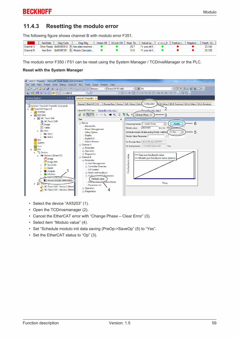
Modulo
Function description 59Version: 1.5
11.4.3 Resetting the modulo errorThe following figure shows channel B with modulo error F351.
The modulo error F350 / F51 can be reset using the System Manager / TCDriveManager or the PLC.
Reset with the System Manager
• Select the device “AX5203” (1).• Open the TCDrivemanager (2).• Cancel the EtherCAT error with “Change Phase – Clear Error” (3).• Select item “Modulo value” (4).• Set “Schedule modulo init data saving (PreOp->SaveOp” (5) to “Yes”.• Set the EtherCAT status to “Op” (3).

Modulo
Function description60 Version: 1.5
11.4.4 Clearing the modulo dataIt is possible to clear the modulo data and reset the servo drive to the factory settings.
• Disable the modulo function (1).• Complete the input with “Accept” (2).
• Activate the configuration. • Switch to the EtherCAT phase “Bootstrap” (3).• Switch to EtherCAT phase „OP“ (3).
The affected IDNs are changed automatically. The modulo data are shown as an example.
Saved modulo data Reset modulo data

Motor types and operation modes
Function description 61Version: 1.5
12 Motor types and operation modesIn this chapter the relationships between physical motor types, feedback systems and the necessaryoperation mode will be explained.
Functionality from firmware v2.12
The firmware V2.12 enables the operation of voice coil motors with feedback system and (a)synchronousservomotors with and without feedback (sensorless regulation).
Structure of the parameter P-0-0050 (Motor construction type)
The functional principle ofthe motor (asynchronous/synchro-nous) and the type of con-struction (rotary/linear) aredefined in this parameter.
Structure of the parameter P-0-0451 (Current controller settings)
In Control mode the opera-tion mode is selected in rela-tion to the predetermined motor type (P-0-0050). Please refer to the table below for the relationships.
Relationships between motor type and operation mode
Case Motor type Settings in P-0-0050 Settings in P-0-04511 Rotary synchronous servomotor with feed-
backFunctional principle = 0: synchronous
Construction = 0: rotary
Functional principle replacement = 0 (Default)
Control mode = 0: Field-ori-ented current control withfeedback
2 Linear synchronous servomotor with feed-back
Functional principle = 0: synchronous
Construction = 1: linear
Functional principle replacement = 0 (Default)
Control mode = 0: Field-ori-ented current control withfeedback
31) Rotary synchronous servomotor withoutfeedback
Functional principle = 0: synchronous
Construction = 0: rotary
Functional principle replacement = 0 (Default)
Control mode = 4: Field-ori-ented current control withoutfeedback
4 Rotary asynchronous servomotor withfeedback
Functional principle = 1: asynchronous
Construction = 0: rotary
Functional principle replacement = 0 (Default)
Control mode = 0: Field-ori-ented current control withfeedback
52) Rotary asynchronous servomotor withoutfeedback
Functional principle = 1: asynchronous
Construction = 0: rotary
Functional principle replacement = 0 (Default)
Control mode = 2: U/f control
orControl mode = 3: U/f controlwith independent feedback
63) Rotary voice coil servomotor with feedback Functional principle = 0: synchronous
Construction = 0: rotary
Functional principle replacement = 1: VoiceCoil
Control mode = 5: Currentcontrol with feedback
73) Linear voice coil servomotor with feedback Functional principle = 0: synchronous Construction = 1: linearFunctional principle replacement = 1: VoiceCoil
Control mode = 5: Currentcontrol with feedback
1): It is absolutely necessary to set Mode in parameter P-0-0464 to 1: EMF-based observer.2): In the case of an asynchronous servomotor and the operation mode U/f control with independentfeedback (setting in P-0-0451), an independent external encoder can additionally be read.3): As soon as you select a voice coil motor in parameter P-0-0050 the range in Functional principle(synchronous / asynchronous) will be overwritten.
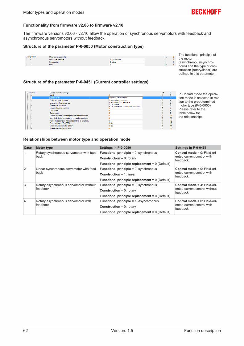
Motor types and operation modes
Function description62 Version: 1.5
Functionality from firmware v2.06 to firmware v2.10
The firmware versions v2.06 - v2.10 allow the operation of synchronous servomotors with feedback andasynchronous servomotors without feedback.
Structure of the parameter P-0-0050 (Motor construction type)
The functional principle ofthe motor (asynchronous/synchro-nous) and the type of con-struction (rotary/linear) aredefined in this parameter.
Structure of the parameter P-0-0451 (Current controller settings)
In Control mode the opera-tion mode is selected in rela-tion to the predetermined motor type (P-0-0050). Please refer to the table below for the relationships.
Relationships between motor type and operation mode
Case Motor type Settings in P-0-0050 Settings in P-0-04511 Rotary synchronous servomotor with feed-
backFunctional principle = 0: synchronous
Construction = 0: rotary
Functional principle replacement = 0 (Default)
Control mode = 0: Field-ori-ented current control withfeedback
2 Linear synchronous servomotor with feed-back
Functional principle = 0: synchronous
Construction = 1: linear
Functional principle replacement = 0 (Default)
Control mode = 0: Field-ori-ented current control withfeedback
3 Rotary asynchronous servomotor withoutfeedback
Functional principle = 0: synchronous
Construction = 0: rotary
Functional principle replacement = 0 (Default)
Control mode = 4: Field-ori-ented current control withoutfeedback
4 Rotary asynchronous servomotor withfeedback
Functional principle = 1: asynchronous
Construction = 0: rotary
Functional principle replacement = 0 (Default)
Control mode = 0: Field-ori-ented current control withfeedback

Parameter set switchover
Function description 63Version: 1.5
13 Parameter set switchover
Note
Reference values for the parameter set switchover:S-0-0216; S-0-0217; S-0-0219; S-0-0254; P-0-0360; P-0-0361
The parameters of the AX5000 servo drive contain reference values or commands.
A distinction is made between:• S-IDNs (e.g. S-0-0206): Standard Sercos parameters, which are automatically provided in the start-up
list of the servo drive. The value ranges and functions cannot be changed / configured.• P-IDNs (e.g. P-0-0001): Custom IDNs, which are set by the NC (CNC) program. The value ranges and
functions can be configured in the TC Drive Manager.
The standard parameters are not relevant for the parameter set switchover. In an application, switchingtakes place within a very short time. The AX5000 servo drive are configured with an internal version. Thisenables faster switching than with the EtherCAT master.
Parameter sets
The Sercos specification stipulates that all parameters can exist n times. In this way parameter sets areformed. The AX5000 may contain up to eight different parameter sets. The parameter sets are identified viathe type key of the IDNs.
Configuration
A parameter set can be configured by entering the corresponding parameters in IDN S-0-0219 (list ofparameter sets). Only the IDNs entered here are available for a parameter set switchover. The other IDNsretain the value stored in parameter set "0".
Selection
A parameter set is selected via IDN S-0-217 "Parameter set preselection". Numbers 0-7 are entered in thisIDN as required.
Type key
Infographic Identifying letter and definitionx S = standard Sercos parameters
P = product-specific parametersy Corresponding parameter set (0 – 7)z Serial number

Parameter set switchover
Function description64 Version: 1.5
13.1 Switching to a parameter set
Parameter sets are switched via IDN S-0-0216"Switch parameter set (pc)". During the switchoverthe parameter listed in IDN S-0-0219 are switched tothe parameter set with the number defined in IDNS-0-0217 (0-7).
13.2 Parameter description
IDN S-0-0216 (Switch parameter set)
Command for executing the parameter set switchover
IDN S-0-0217 (Parameter set preselection)
The parameter number for the switchover is entered in this IDN. If, for example, 2 is entered here and thenthe command S-0-0216 is executed, the parameter of parameter set S/P-2-xxxx are activated.
IDN S-0-0219 (IDN-list of parameter set)
This table contains all IDNs for which parameter sets 0 to 7 are available.
IDN S-0-0254 (Actual parameter set)
This IDN indicates the currently active parameter set.
IDN P-0-0360 (Parameter set prearrangement)
This IDN is used to specify how many parameter sets are prepared for switchover in the AX5000. If this IDNis parameterized to 3 it is possible to switch between parameter sets 0 to 3.
IDN P-0-0361 (Parameter set configuration)
This list is intended for the IDNs to be switched, which should also be listed in S-0-0219. The parameters ofthe IDNs entered here are prepared for parameter set switchover and switched accordingly.

Probe unit (functionality)
Function description 65Version: 1.5
14 Probe unit (functionality)A probe unit is a hardware-oriented functional group that can store the actual axis position for aparameterizable event. The event may be an edge of a digital input in the drive, for example. The position isstored immediately without significant delay for subsequent evaluation by the control system.
The probe unit of the drive can be used for event-controlled position detection via the user program„MC_TouchProbe“. An additional application is logging of a reference position during homing („MC_Home“),if the NC referencing mode is set to „Hardware latch“.
In any case, the probe unit has to be parameterized before it can be used. The following configuration refersto an AX5000 servo drive (SoE). More generally, it can also be used for parameterization of a SERCOSdrive.
SERCOS parameters
Parameter Value EtherCAT Transition (Startup) DescriptionS-0-0303 405 P -> S Allocation of real-time Control bit 2S-0-0307 409 or 410 P -> S Allocation of real-time Status bit 2S-0-0169 1, 2, 3 P -> S Probe control parameterS-0-0170 3 S -> O Probing cycle procedure command
Process data – cyclic data between drive and NC axis
Parameter DescriptionS-0-0130 Probe value positive edgeS-0-0131 Probe value negative edge
14.1 Parameterization
The probe unit is parameterized via a configuration dialog of theAX5000 servo drive. In multi-channel devices a probe unit is avail-able for each channel.
Proceed as follows to parameterize the probe unit:
• Select a signal source (in our sample „Mux2“ on the left) fortriggering the probe unit.
• Assign a digital input of the AX5000 servo drive (0-7) to thesignal source.
Homing: Select the configuration „Mux2“ for homing with evaluation of theencoder zero track. „Reference signal feedback“ is only available inthis signal source.

Probe unit (functionality)
Function description66 Version: 1.5
The following window (left) appears for a configuration with „Refer-ence signal feedback“ .
• Confirm with OK
The "Feedback 1" menu appears.
• Select the source of the "Feedback referencesignal" (usually „Zero index“).
Further settings are required in the "Probe unit" window (left).
• Press the „Logic“ button.
The trigger signal can be linked to a further signal source (Mux 2).The simplest case consists of a signal source and the combinationlogic ("logic operation").
• Specify which signal edge (positive or negative) should beevaluated in the signal sequence (Pos Edge or Neg Edge).
• The decision for a particular signal edge is made duringparameterization of the AX5000 servo drive. It is notpossible to select it later in the control program (NC / CNC).
In the last step the "Mode" and the activation type are specified.
Mode probe 1: 0 Single measuring: After each measurement event the new process must be activatedthrough a 0-1 enable switch (default).Mode probe 1: 1 Continuous measuring:The measurement is repeated as long as enable remains 1.Auto activation: 0:Activation with S-0-0170:The probe unit is activated with command S-0-0170 from the userprogram (default).Auto activation 1: Auto activation from SafeOp to Op:The probe unit is enabled automatically when the AX5000 switchesfrom SafeOp state to Op.
Once all options have been selected, press "Modify settings in startup list and process data". An overview appears, which lists the pa-rameters and process data to be modified. Confirm with OK. If the AX5000 is properly linked to an NC axis, the settings required for thisaxis are implemented automatically.

Position offset
Function description 67Version: 1.5
15 Position offset
Note
TerminologyIn this documentation, the term offset tends to be used to describe the function of the position offset.
An offset can be configured if an absolute encoder is used in the AX5000. The value can be stored in themotor encoder, in the AX5000 or in the startup list. The offset is taken into account when the AX5000 startsup. It is added to the absolute encoder position. The result is reported to the higher-level controller as anactual value.
In contrast to the offset stored in the TwinCAT NC, the offset stored in the AX5000 or in the encoder can alsobe modified and stored from the PLC (see procedure described below).
Parameters involved
The meaning of the parameters in relation to the offset is explained in the following sections.
Note
Reference values of the position offsetS-0-0051; P-0-0159, P-0-0271; P-0-0272; P-0-0273; P-0-0274; P-0-0275; P-0-0278
Prerequisites
The AX5000 requires firmware v2.06 build 8 or higher. For positioning, an absolute encoder must beconnected to the AX5000. The offset can also be used with a single-turn encoder or a resolver, which use anabsolute counting method within a revolution.
Procedure
A PLC function block is available in the library TC2_MC2_Drive under TwinCAT 3 for saving or modifying the offsetfrom a user program:The description of this PLC function block can befound in the Beckhoff Online Infosys, for example.The offset is stored in increments. The TC DriveManager should therefore be used for entering ormodifying the offset without a PLC program. It dealswith the conversion between user units andincrements. The following page becomes active, if theAX5000 is linked with an NC axis:
It shows settings from the NC (1) and whether anoffset is already active (2). To save a new offset,enter the value in user units and select the storagelocation (3). Use the "Activate" button (4) to store andenable the offset. The "Activate" function can only beexecuted if the axis is not in controlling mode.

Position offset
Function description68 Version: 1.5
If the AX5000 is linked to a CNC axis, the TC DriveManager does not "know" the feed constant. Thewindow shows fewer data, and the offset must beentered in increments.The "Table View" button (5) can be used to switch theview in both cases (NC or CNC) (see diagram below).
The parameters involved and their current values aredisplayed here. Use the „Return“ button (6) to returnto the original view (top diagram).
Behavior when components are replaced
If a faulty motor or servo drive (AX5000) is replaced, the axis should be prevented from starting with anincorrect offset, which could result in damage. The following scenarios are conceivable, depending on wherethe offset is stored and which component is replaced:
Offset stored in encoder (P-0-0275 „Use encoder memory position offset“)Replaced ResultMotor: No offset is stored in the encoder for the new motor
EtherCAT status: Err PreOpDrive status: Error F341No position offset available
Motor:An (incorrect) offset is already stored for the newmotor.
EtherCAT status: OpDrive status: Ready D012
Servo drive AX5000 (with or without stored offset) EtherCAT status: OpDrive status: Ready D012
Offset stored in AX5000 (P-0-0275 “Use drive memory position offset”)Replaced ResultMotor:No offset is stored in the encoder for the new motor
EtherCAT status: Err PreOpDrive status: Error F340, position offset invalid,wrong serial number
Motor:An (incorrect) offset is already stored for the newmotor.
EtherCAT status: Err PreOpDrive status: Error F340, position offset invalid,wrong serial number
Servo Drive AX5000:New device without stored offset
EtherCAT status: Err PreOpDrive status: Error F341, no position offset available
Servo drive AX5000 (with or without stored offset) EtherCAT status: Err PreOpDrive status: Error F340, position offset invalid,wrong serial number
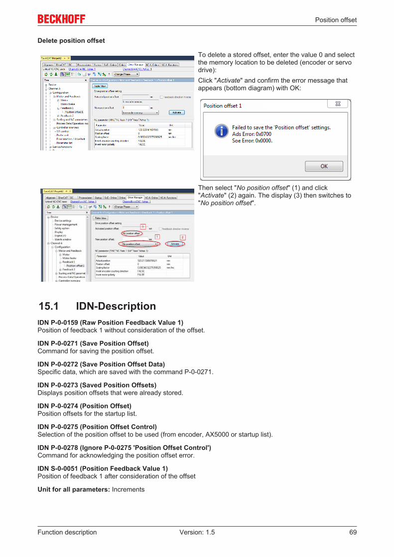
Position offset
Function description 69Version: 1.5
Delete position offset
To delete a stored offset, enter the value 0 and selectthe memory location to be deleted (encoder or servodrive):Click "Activate" and confirm the error message thatappears (bottom diagram) with OK:
Then select "No position offset" (1) and click"Activate" (2) again. The display (3) then switches to"No position offset".
15.1 IDN-DescriptionIDN P-0-0159 (Raw Position Feedback Value 1)Position of feedback 1 without consideration of the offset.
IDN P-0-0271 (Save Position Offset)Command for saving the position offset.
IDN P-0-0272 (Save Position Offset Data)Specific data, which are saved with the command P-0-0271.
IDN P-0-0273 (Saved Position Offsets)Displays position offsets that were already stored.
IDN P-0-0274 (Position Offset)Position offsets for the startup list.
IDN P-0-0275 (Position Offset Control)Selection of the position offset to be used (from encoder, AX5000 or startup list).
IDN P-0-0278 (Ignore P-0-0275 'Position Offset Control')Command for acknowledging the position offset error.
IDN S-0-0051 (Position Feedback Value 1)Position of feedback 1 after consideration of the offset
Unit for all parameters: Increments

Power Management
Function description70 Version: 1.5
16 Power Management
Note
Power management reference values:P-0-0201; P-0-0202; P-0-0203; P-0-0214
The AX5000 is normally operated with a 3-phase AC voltage. This is rectified in the device with the aid of abridge rectifier and charges the DC link. Furthermore, there is an option to input a DC voltage.
Parameterization:• Mains voltage with P-0-0201• Tolerances with P-0-0202 and P-0-0203• DC link connection with P-0-0214
The further basic parameterization then takes place according to the following criteria:• Voltage on X01:
AC 3-phase or single -phase or DC input.All monitors are activated (default parameterization). The phase monitoring must be deactivated in the case of “AC single-phase” or “DC”.
• DC voltage on X02:In P-0-0204, activate the commands “DisableUmainMonitoring” and “DisableUmainLossMonitoring”.There is NO LONGER ANY DEVICE PROTECTION via X01! Further information in the section DCinput.
16.1 Mains voltage monitoringThe servo drive monitors the connected mains voltage for minimum and maximum values. To this end thevalue of the connected voltage and the permitted tolerance values are specified. The diagram below showsthe TCDriveManager configuration option. The section outlined in red is used for configuring the mainsvoltage with min./max. values. Mains phase monitoring is activated or deactivated in the section outlined inpurple. Phase monitoring is always based on 3-phase mains.
Note
phase monitoringPhase monitoring must be disabled for single-phase mains supply, to facilitate commission-ing of the servo drive.

Power Management
Function description 71Version: 1.5
16.2 DC supplyFor special applications it may be useful to input a DC voltage. Several things need to be observed for theconnection and the parameter settings, which are described below.
The DC voltage can be connected:• via the AC input (X01) or• directly into the DC link (X02).
Voltage parameterizationThe desired DC voltage is set with P-0-0201“Nominal mains voltage”. The controller automaticallyrecognizes the DC voltage form during theinitialization (from firmware v2.10).In the case of small DC voltages, the parametersP-0-0202 and P-0-0203 “Mains voltage tolerance”should be 24 V or 48 V (at least 20%, better 30%).Due to the tolerances when measuring the voltages,an error would otherwise frequently be caused.
If the exchange of energy between several AX5000 devices is desired, the following parameterization mustbe used:
DC-Link connection mode (P-0-0214): "0x0003: AX5x01-AX5x25 [X02] Static external DC Link connection"
DC input via the wide-range voltage input – X01
In the case of input via X01, note that (as with the single-phase connection) only two of the six rectifierdiodes conduct the current. The same limitations apply as to the power or output current (see startupmanual). The voltage can be connected at L1 and L3/N.
Terminal point Connection3-phase 1-phase
L1 Phase L1 Phase L1L2 Phase L2 not usedL3 / N Phase L3 Neutral conductorPE Protective conductor Protective conductor
DC input via the DC link input – X02
The charging circuit for the DC link is inactive. The user must ensure that the starting current does notbecome too high when the voltage is switched on.
For the calculation, for example, of a resistor that limits the starting current, the DC link of the AX5000 is tobe regarded as a short-circuit at the moment of switching on.
Be sure to observe the correct polarity of the connection (DC+, DC-)!
Terminal point ConnectionDC + DC link + External brake resistor and DC link
connectionDC - DC link -
The table below shows values that may not be exceeded:
Device Max. starting currentAX5x01 – AX5112 10AAX5118 – AX5140 20A

Power Management
Function description72 Version: 1.5
The settings in the Power Management Control Word(P-0-0204) marked below are important in the case ofinput via X02 (from firmware V2.10):Important! With the parameterization “Disable Umainloss monitoring”, the device protection with regard tomains voltage interruptions at X01 is switched off.Therefore, only switch the monitors off in case of DCinput at X02.
16.3 Diagnostics for external brake resistors
Note
Reference values for the external brake resistor:P-0-0207; P-0-0208; P-0-0209; P-0-0210; P-0-0218; P-0-0219; P-0-0220; P-0-0221
This chapter provides basic information on dimensioning and configuration of external brake resistors. Theparameters described in this chapter can be recorded with the TwinCAT Scope View for diagnosticpurposes.
If an internal brake resistor is used, the configuration takes place via the IDNs:• P-0-0209 (Internal brake resistor actual continuous power) in watts and• P-0-0218 (Internal brake resistor actual peak energy) in %
If an external brake resistor is used, the configuration takes place via the IDNs:• P-0-0210 (External brake resistor actual continuous power) in watts and• P-0-0219 (External brake resistor actual peak energy) in %
"Actual continuous power" is an arithmeticallyaveraged value of the actual power. Even afterseveral typical machine cycles the value of P-0-0210(P-0-0209 internally) must always remain below thevalue of the continuous power of the brake resistor.A cycle time of 100 s is assumed for calculating thebrake resistor power. Monitoring should thereforetake place over this time as a minimum. Thepermissible value for the continuous power can befound in P-0-0207 (internal brake resistor) orP-0-0208 (external brake resistor):"Actual peak energy" indicates the greatest measuredbraking energy, much like a drag indicator does. Thesituation with the maximum required peak brakingpower, e.g. emergency stop, is supposed to bedetermined and tested. In the process, the value ofP-0-0218 (internal) or P-0-0219 (external) should stayconsiderably below 100%.For more exact observations it is possible to recordthe parameters with the software oscilloscope. If forexample the velocity or the position is recorded, abetter allocation of the current braking power to themachine cycle is possible. To this end the parametersmust be inserted into the process image beforehand:

Power Management
Function description 73Version: 1.5
Note
Further information on external brake resistors can be found at:Information on mechanical and electrical installation, dimensions and technical data can befound in the system manual for the AX5000 servo drive under: „Accessories – Externalbrake resistor – AX2090-BW5x-xxxx“.
For further analysis peak values are recorded in the parameters P-0-0220 (internal brake resistor) or P-0-0221 (external) with respectto the duty cycle.
Duty cycle (DC) = switch-on time / cycle time (machine cycle) x 100%Beckhoff specifies an overload factor for the brake resistors, depending on the duty cycle (see diagram below):
Multiplied by the power rating, the permissible short-term power results from the overload factor dependenton the duty cycle:
Short-term power = Power rating x Overload factor (ÜF)
For the AX5000 energy values were calculated for the supported brake resistors from the power rating, dutycycle and overload factor and saved as parameters. They can be found for the internal brake resistor inP-0-0207 and after selecting an external brake resistor P-0-0208.
Sample: AX2090BW50-1600 with 47 ohm and 1600W power rating
Overload factor for 1% duty cycle: 30
1% duty cycle for 100s cycle time corresponds to 1s
1s x 1600W x 30 = 48000J
Correspondingly the other saved values result:
Duty cycle [%] 40 20 10 1 0.1Overload factor 2.2 3.9 7 30 144.375Peak E. [J] 140800 124800 112000 48000 23100
When the brake resistor becomes active, the software program calculates the current energy values, relatedto the duty cycle and presents the maximum values in P-0-0220 or P-0-0221. Both parameters are resetwhen the device is restarted (=0). The values entered in operation are preserved until the next restart or untilthey are overwritten by the user. They can be compared with the permissible values in P-0-0207 (internalbrake resistor) or P-0-0208 (external). As a result it may be possible to influence the braking power in criticalregions by modifying the cycle.
The greatest percentage value is entered in P-0-0218 or P-0-0219 (in %) (see above).
Power Management
Function description74 Version: 1.5
16.4 DC link charging and monitoringThe new state machines for “Umain” and “DC link charging” ensure high availability and at the same timeimproved protection of the servo drive. Basis is the fast measurement of the mains (X01) and DC link voltage.
All servo drives in a common DC link group must have a firmware version ≥ v2.10.
The charging of the DC link is faster and the axis is thus ready for operation sooner.
The voltage tolerance of the mains voltage for error messages has become larger:• By default the overvoltage limit is 120% of the mains voltage• and the undervoltage limit 70% of the mains voltage.
If larger values are desired, they can be entered with P-0-0202 (overvoltage, values > 20%) and P-0-0203(undervoltage, values > 30%).
The warnings for mains overvoltage or undervoltage are always triggered at the limits defined by P-0-0202(overvoltage) and P-0-0203 (undervoltage). This means in the case of P-0-0202 >20% and voltage values > rated voltage (P-0-0201) + P-0-0202 [in %]that the error is triggered simultaneously with the warning.
In the case of undervoltage, error and warning are triggered simultaneously if P-0-0203 > 30% and thepresent voltage is < P-0-0201 – P-0-0203 [in %].
Mains interruptions do not cause an error message as long as the DC link voltage approximatelycorresponds to the last measured mains voltage. In the case of low energy requirement of the axes it is quitepossible to bridge mains interruptions lasting up to one second.
The request „Axis to move until no voltage is present“ (P-0-0204 „DisableDcLinkVoltageMonitoring“) results in no error message being generated in relation to theDC link voltage. At a lower voltage, however, not all speeds can be reached. The application must thereforemonitor the DC link voltage.

Thermal motor model
Function description 75Version: 1.5
17 Thermal motor model
Note
Reference values for the thermal motor model:S-0-0012; S-0-0111, S-0-0135; S-0-0196, P-0-0052; P-0-0061; P-0-0062, P-0-0066 andP-0-0063.
The thermal motor model calculates the current thermal utilization (P-0-0063 in %) of the motor. Thisutilization display serves to determine the application-specific utilization reserves. Furthermore, the thermalmotor model offers motor protection by means of the dynamic detection of overloads. The motor data forBeckhoff servo motors from the series AM8000 originate from the electronic name plate (offline from themotor data files *.xeds). The motor data generator can be used to create motor data files for third-partymotors.
If a temperature sensor (e.g. KTY83-110, KTY84-130, PT1000) is installed in the motor that allows atemperature evaluation over the entire operating temperature range (see motor technical data), the motor isinitialized in accordance with the current temperature.
The operating temperature cannot be measured if PTC thermistors are used that exhibit a fast increase inthe resistance value in the region of the nominal response temperature (motor cut-off temperature). In thiscase the motor is initialized in accordance with the max. permissible ambient temperature (40 °C). It shouldbe noted here that after switching off the 24 V system supply a waiting time (5 times the motor time constantP-0-0062, time constant 1) is required before switching on again. This ensures the thermal motor protectionwith the motor model. The value of the load display is incorrect if the waiting time is not adhered to.
17.1 Functionality from firmware v2.10A more precise thermal motor model is used from firmware v2.10. This second order model calculates thewinding temperature with the help of the winding time constant (P-0-0062, time constant 2). Furthermore, aspeed-dependent calculation of the iron losses is carried out. This ensures a considerably improvedutilization of the motors.
Note
Calculation of the copper and iron losses!For the calculation of the copper and iron losses must be the IDNs S-0-0111, S-0-0196 andP-0-0066 filled with reliable and engine-specific data!
17.2 Functionality up to firmware v2.06Up to and including firmware v2.06, the copper losses are used in connection with the thermal timeconstants of the stator and the housing (P-0-0062, time constant 1) for a utilization display.
Motor windings with a small thermal mass are protected by means of a time limitation of the peak current(P-0-0052, default: 3 s).
The model is initialized independently of the temperature sensor on the basis of the max. permissibleambient temperature (40 °C).
Note
Calculation of the copper losses!For the calculation of the copper losses must be the IDNs S-0-0111 and P-0-0066 filledwith reliable and engine-specific data!
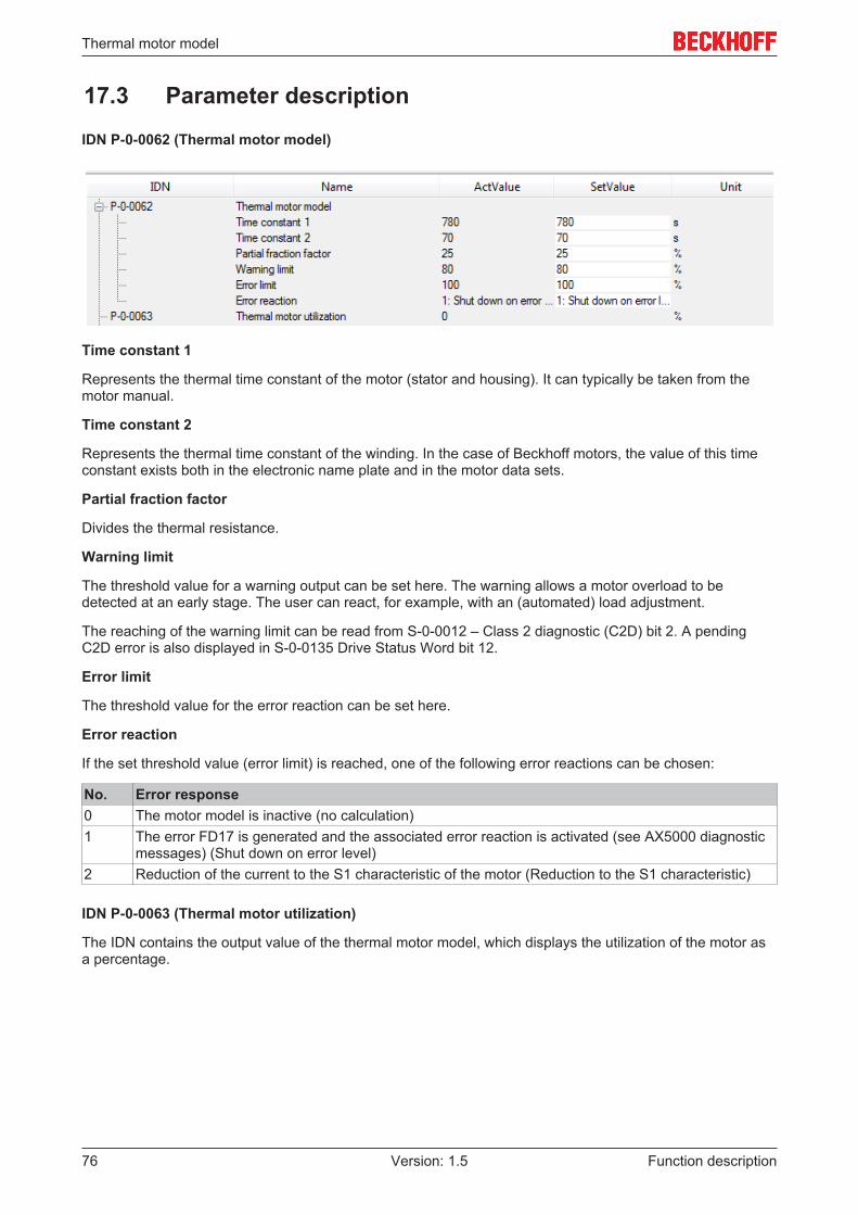
Thermal motor model
Function description76 Version: 1.5
17.3 Parameter description
IDN P-0-0062 (Thermal motor model)
Time constant 1
Represents the thermal time constant of the motor (stator and housing). It can typically be taken from themotor manual.
Time constant 2
Represents the thermal time constant of the winding. In the case of Beckhoff motors, the value of this timeconstant exists both in the electronic name plate and in the motor data sets.
Partial fraction factor
Divides the thermal resistance.
Warning limit
The threshold value for a warning output can be set here. The warning allows a motor overload to bedetected at an early stage. The user can react, for example, with an (automated) load adjustment.
The reaching of the warning limit can be read from S-0-0012 – Class 2 diagnostic (C2D) bit 2. A pendingC2D error is also displayed in S-0-0135 Drive Status Word bit 12.
Error limit
The threshold value for the error reaction can be set here.
Error reaction
If the set threshold value (error limit) is reached, one of the following error reactions can be chosen:
No. Error response0 The motor model is inactive (no calculation)1 The error FD17 is generated and the associated error reaction is activated (see AX5000 diagnostic
messages) (Shut down on error level)2 Reduction of the current to the S1 characteristic of the motor (Reduction to the S1 characteristic)
IDN P-0-0063 (Thermal motor utilization)
The IDN contains the output value of the thermal motor model, which displays the utilization of the motor asa percentage.

Torque (Force) – Controller Structure
Function description 77Version: 1.5
18 Torque (Force) – Controller Structure
Note
TerminologyBased on this documentation, the term that is usually used for the functional description ofthe torque and force controller structure is torque controller structure. Force controller structure is used forlinear motors.
Note
Parameters used for the torque (force) controller structure:S-0-0080; S-0-0081, S-0-0082, S-0-0083, S-0-0084, S-0-0092, P-0-0002; P-0-0074,P-0-0092, P-0-0094, P-0-0454, P-0-0459, P-0-0465, P-0-0505
18.1 Functionality from firmware v2.10
Note
Torque-Interface!If the torque interface is active, the torque setpoint (S-0-0080) must be mapped directly inthe process data. The mapping then enables these process data to be linked externally(NC / CNC / PLC).
The torque control structure is realized through a current controller and a proportionality relationship betweencurrent and torque. The torque controller structure enables the torque requirement of the higher-level velocitycontroller to be met. The characteristic torque/current curve therefore maps the motor characteristics(saturation effect).
This results in the following relationships for representing the torque:
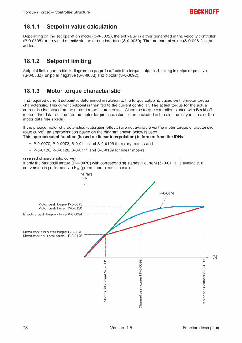
Torque (Force) – Controller Structure
Function description78 Version: 1.5
18.1.1 Setpoint value calculationDepending on the set operation mode (S-0-0032), the set value is either generated in the velocity controller(P-0-0505) or provided directly via the torque interface (S-0-0080). The pre-control value (S-0-0081) is thenadded.
18.1.2 Setpoint limitingSetpoint limiting (see block diagram on page 1) affects the torque setpoint. Limiting is unipolar positive(S-0-0082), unipolar negative (S-0-0083) and bipolar (S-0-0092).
18.1.3 Motor torque characteristicThe required current setpoint is determined in relation to the torque setpoint, based on the motor torquecharacteristic. This current setpoint is then fed to the current controller. The actual torque for the actualcurrent is also based on the motor torque characteristic. When the torque controller is used with Beckhoffmotors, the data required for the motor torque characteristic are included in the electronic type plate or themotor data files (.xeds).
If the precise motor characteristics (saturation effects) are not available via the motor torque characteristic(blue curve), an approximation based on the diagram shown below is used. This approximated function (based on linear interpolation) is formed from the IDNs:
• P-0-0070, P-0-0073, S-0-0111 and S-0-0109 for rotary motors and• P-0-0126, P-0-0128, S-0-0111 and S-0-0109 for linear motors
(see red characteristic curve). If only the standstill torque (P-0-0070) with corresponding standstill current (S-0-0111) is available, aconversion is performed via KT0 (green characteristic curve).

Torque (Force) – Controller Structure
Function description 79Version: 1.5
18.1.4 Current controllerThe current controller represents the inner controller of the cascading control loop structure. Based on field-oriented control, an advanced PI controller provides the current components required for the requestedoperation mode S-0-0032. The q-current is proportional to the torque (for linear motors it is proportional tothe force). The settings for the current controller parameters Kp and TN are based on the motor winding dataand the optimum bandwidth (compromise between dynamics and noise generation).
For Beckhoff motors the settings for the optimum bandwidth are taken from the electronic type plate (oroffline from the motor data files *.xeds). For the most applications these settings can be left unchanged. Themotor data generator can be used to create motor data files for third-party motors.
Corresponding pre-controls are applied to deal with systematic interference:• Load and mains voltage-dependent fluctuations of the DC link voltage• Induced motor voltage and• Voltage over the winding inductance.
18.1.4.1 Generation of the output voltage
Generation of the output voltage for the AX5000 servo drive is based on a PWM clock frequency of 8 kHz. Inorder to reach an acceptable compromise between power loss and requirements for the insulation system ofthe motor, the AX5000 operates with a maximum rate of voltage rise (du / dt) of 5 kV per µs.
Note
IDN P-0-0001 (Switching frequency of the IGBT module)Further information on the clock frequency of the AX5000 servo drive can be found in thedescription of the IDN parameters (www.beckhoff.de) under:P-0-0001 (Switching frequency of the IGBT module).
The voltage profile at the servo drive output described above results in certain requirements for:
• the cable configuration,• the cable length and• the insulation system of the motor.
If Beckhoff cables and motors are used, all requirements are met, based on the procedures described inchapter „Motors and cables for servo drives“.
Note
EMC-compliant commissioningFurther information on EMC-compliant commissioning can be found in theAX5000 EMC leaflet, which is available on the Beckhoff website (www.beckhoff.de).
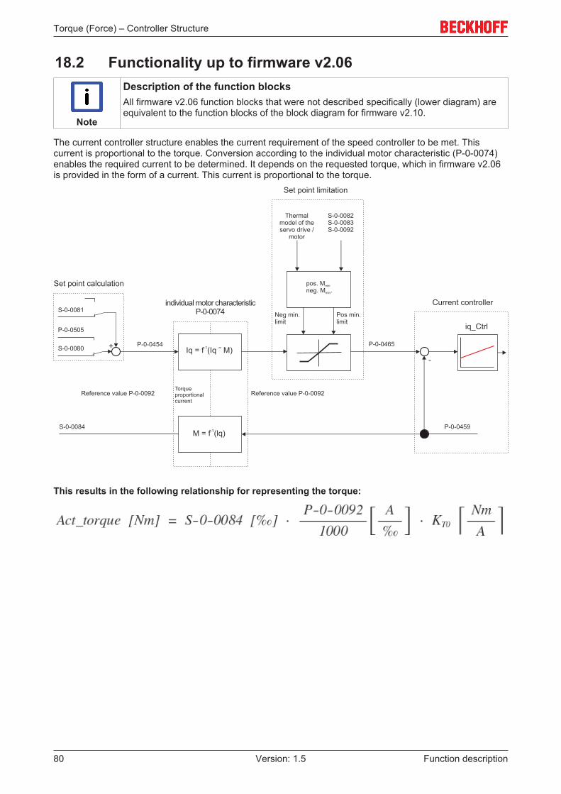
Torque (Force) – Controller Structure
Function description80 Version: 1.5
18.2 Functionality up to firmware v2.06
Note
Description of the function blocksAll firmware v2.06 function blocks that were not described specifically (lower diagram) areequivalent to the function blocks of the block diagram for firmware v2.10.
The current controller structure enables the current requirement of the speed controller to be met. Thiscurrent is proportional to the torque. Conversion according to the individual motor characteristic (P-0-0074)enables the required current to be determined. It depends on the requested torque, which in firmware v2.06is provided in the form of a current. This current is proportional to the torque.
This results in the following relationship for representing the torque:

Torque (Force) – Controller Structure
Function description 81Version: 1.5
18.3 Parameter description
IDN P-0-0074 (Motor torque characteristic)
The parameter contains 10 ordered pairs of numbers. They describe the relationship between torque-formingcurrent and torque, as a function of M = f (lq).
IDN P-0-0092 (Configured channel peak current)
Preset peak current of the channel. The peak current is usually preset to twice the rated motor current.
Unit: ampere (A)
IDN P-0-0094 (Configured channel peak torque)
Preset peak torque of the motor. The peak torque depends on the control parameter. The parameter isrelated to the motor characteristics and parameter P-0-0092 (from firmware v2.10).
Unit: newton meter (Nm)
IDN P-0-0454 (Effective torque command value)
Set torque value based on parameter P-0-0094. This parameter matches parameter P-0-0456 (actual motorcurrent phase).
Unit: per thousand; one-tenth of a per cent (‰)
IDN P-0-0459 (Actual torque generating current)
Actual value of torque-forming current, based on parameter P-0-0092. This parameter matches the actualtorque value S-0-0084. The parameters are related via the motor characteristics.
Unit: ampere in ‰
IDN P-0-0465 (Effective current command value)
Instantaneous set current value, based on parameter P-0-0092. This parameter matches the set torquevalue P-0-0454. The parameters are related via P-0-0454 and P-0-00465.
Unit: ampere in ‰
IDN P-0-0505 (Velocity controller output)
Output value of the torque controller, based on parameter P-0-0094. The parameter is only used duringcommissioning of the higher-level speed controller (from firmware v2.10).
Unit: per thousand; one-tenth of a per cent (‰)
IDN S-0-0081 (Additiv torque command value)
Pre-control value for acceleration pre-control. This value is added directly to parameter P-0-0505 andindicates a torque based on parameter P-0-0094. The parameter is only used during commissioning of thehigher-level speed controller (from firmware v2.10).
Unit: per thousand; one-tenth of a per cent (‰)
IDN S-0-0082 (Positive torque limit value)
The parameter limits the set torque/force value of the controller. The upper positive limit is specified (unipolarpos.). If this limit is exceeded, the drive sets bit 3 of S-0-0013.
The reference value is P-0-0092 and P-0-0094 (from firmware v2.10).
Unit: per thousand; one-tenth of a per cent (‰)

Torque (Force) – Controller Structure
Function description82 Version: 1.5
IDN S-0-0083 (Negativ torque limit value)
The parameter limits the set torque/force value of the controller. The lower negative limit is specified(unipolar neg.). If the value falls below this, the drive sets bit 3 of S-0-0013.
The reference value is P-0-0092 and P-0-0094 (from firmware v2.10).
Unit: per thousand; one-tenth of a per cent (‰)
IDN S-0-0084 (Torque feedback value)
Actual value of torque current, based on parameter P-0-0094. The parameters are related via the motorcharacteristics. (from firmware v2.10)
Unit: ampere in ‰
IDN S-0-0092 (Bipolar torque limit value)
The parameter limits the set torque/force value of the controller. The lower negative (bipolar neg.) and upperpositive (bipolar pos.) limit is specified. The lowest value of all set limits applies.
The reference value is P-0-0092 and P-0-0094 (from firmware v2.10).
Unit: per thousand; one-tenth of a per cent (‰)
IDN S-0-0109 (Motor peak current)
Peak current of the motor (according to data sheet)
Unit: ampere (A)
IDN S-0-0111 (Motor continuous stall current)
Standstill current of the motor (according to data sheet)
Unit: ampere (A)

Variable position interface
Function description 83Version: 1.5
19 Variable position interface
Note
Reference values for the variable position interface:S-0-0051; S-0-0053; S-0-0079
If the AX5000 is to transfer a single-turn position with a resolution of more than 20 bits to the controller, thevariable position interface must be used.
The position of the axis is recorded in the AX5000 and handed over to the controller in S-0-0051 with a datalength of 32 bits. Parameter S-0-0079 (Position Resolution) now specifies how many of these 32 bits areused for the single-turn range in S-0-0051* (Position feedback value 1). The remaining bits form the variablemulti-turn range.
*This function also exists in S-0-0053 (Position feedback value 2).
19.1 Functionality from firmware v2.10From AX5000 firmware v2.10 S-0-0079 is writeable and can be parameterized between 220 bits and 230 bits.The single-turn position length in S-0-0051 and S-0-0053 can thus be set from 20 to 30 bits. That results inthe multi-turn position length with 12 – 2 bits. Note that both ranges always change. If the single-turnresolution is increased, the maximum multi-turn count value is reduced.
CaptionsYellow area = variable rangeGrey area = permanently assigned
rangeMT = Multi-turn rangeST = Single-turn range
Commissioning
Parameter S-0-0079 (Position Resolution) can beadjusted via the TC Drive Manager. To do this, go tothe corresponding (controller) channel →Configuration → Scaling and NC parameters. This value (data length) can be manually set by theuser in the TC Drive Manager.The default value for parameter S-0-0079 is 1048576(220) and corresponds to a 20-bit single-turn range.
If parameter S-0-0079 is changed via the TC Drive Manager, the changes necessary for NC take placeautomatically.The following values are then changed in the NC axis under the object Enc (Encoder):
• Scaling Factor Denominator• Encoder Sub Mask
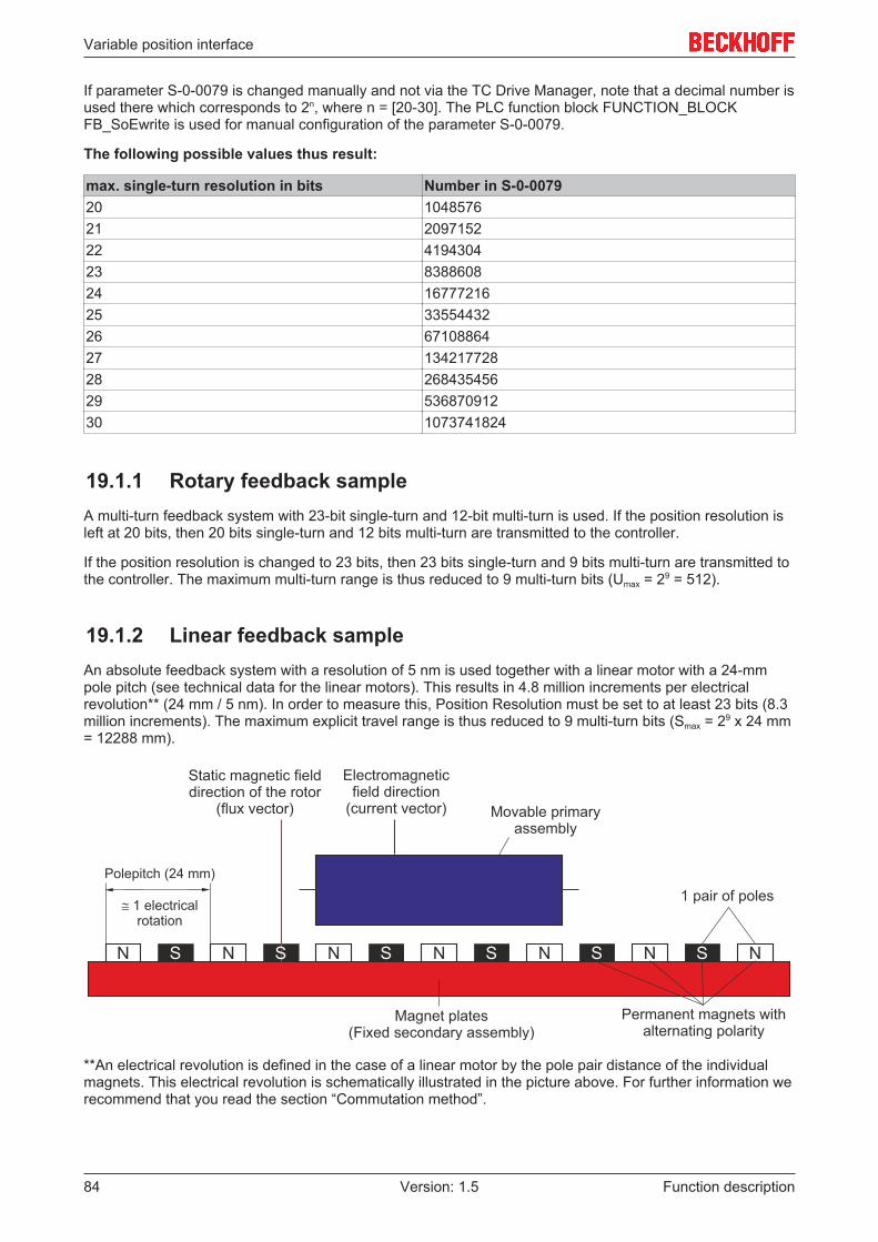
Variable position interface
Function description84 Version: 1.5
If parameter S-0-0079 is changed manually and not via the TC Drive Manager, note that a decimal number isused there which corresponds to 2n, where n = [20-30]. The PLC function block FUNCTION_BLOCKFB_SoEwrite is used for manual configuration of the parameter S-0-0079.
The following possible values thus result:
max. single-turn resolution in bits Number in S-0-007920 104857621 209715222 419430423 838860824 1677721625 3355443226 6710886427 13421772828 26843545629 53687091230 1073741824
19.1.1 Rotary feedback sampleA multi-turn feedback system with 23-bit single-turn and 12-bit multi-turn is used. If the position resolution isleft at 20 bits, then 20 bits single-turn and 12 bits multi-turn are transmitted to the controller.
If the position resolution is changed to 23 bits, then 23 bits single-turn and 9 bits multi-turn are transmitted tothe controller. The maximum multi-turn range is thus reduced to 9 multi-turn bits (Umax = 29 = 512).
19.1.2 Linear feedback sampleAn absolute feedback system with a resolution of 5 nm is used together with a linear motor with a 24-mmpole pitch (see technical data for the linear motors). This results in 4.8 million increments per electricalrevolution** (24 mm / 5 nm). In order to measure this, Position Resolution must be set to at least 23 bits (8.3million increments). The maximum explicit travel range is thus reduced to 9 multi-turn bits (Smax = 29 x 24 mm= 12288 mm).
**An electrical revolution is defined in the case of a linear motor by the pole pair distance of the individualmagnets. This electrical revolution is schematically illustrated in the picture above. For further information werecommend that you read the section “Commutation method”.
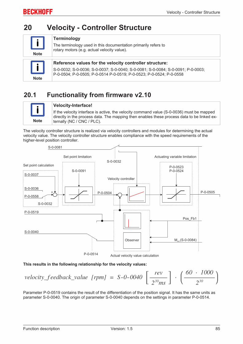
Velocity - Controller Structure
Function description 85Version: 1.5
20 Velocity - Controller Structure
Note
TerminologyThe terminology used in this documentation primarily refers torotary motors (e.g. actual velocity value).
Note
Reference values for the velocity controller structure:S-0-0032; S-0-0036; S-0-0037; S-0-0040; S-0-0081; S-0-0084; S-0-0091; P-0-0003;P-0-0504; P-0-0505; P-0-0514 P-0-0519; P-0-0523; P-0-0524; P-0-0558
20.1 Functionality from firmware v2.10
Note
Velocity-Interface!If the velocity interface is active, the velocity command value (S-0-0036) must be mappeddirectly in the process data. The mapping then enables these process data to be linked ex-ternally (NC / CNC / PLC).
The velocity controller structure is realized via velocity controllers and modules for determining the actualvelocity value. The velocity controller structure enables compliance with the speed requirements of thehigher-level position controller.
This results in the following relationship for the velocity values:
Parameter P-0-0519 contains the result of the differentiation of the position signal. It has the same units asparameter S-0-0040. The origin of parameter S-0-0040 depends on the settings in parameter P-0-0514.

Velocity - Controller Structure
Function description86 Version: 1.5
20.1.1 Setpoint value calculationDepending on the set operation mode (S-0-0032) the control value (P-0-0558) for the position controller isprovided as velocity command value or directly from the interface (S-0-0036). The pre-control value(S-0-0037) is then added.
20.1.2 Setpoint limitingSetpoint limiting (see block diagram on page 1) affects the velocity command value. The limitations arebipolar (S-0-0091).
20.1.3 Velocity controller
Note
The „Velocity controller“ section is currently still in preparation and will be released as soonas possible.
20.1.4 Determining the actual velocity value (differentiation)In the AX5000 a speed signal is calculated from the position signal of the motor feedback (throughmathematical differentiation). This signal quickly responds to changes, but it contains noise and can surge inthe presence of mechanical resonances. Mapping takes place in parameter P-0-0519.
20.1.5 Determining the actual velocity value (Velocity Observer)
Note
Reference values of the Velocity Observer:S-0-0040; S-0-0109; S-0-0111; P-0-0070; P-0-0071; P-0-0073; P-0-0074; P-0-0126;P-0-0127 P-0-0128
An Observer is a system for representing parameters that are difficult to measure, based on a model and known input and measuredvariables.
For frequencies above around 300 Hz the noise associated with the velocity signal calculated from the feedback becomes problematic.The Velocity Observer of the AX5000 is used to solve this problem. It estimates the acceleration from the measured current and fromthis the speed signal (through numerical integration). This speed signal is smoother and less susceptible to mechanical resonances.
When the Velocity Observer is used, up to the set bandwidth the velocity controller takes into account the speed signal calculated fromthe feedback, at higher frequencies it takes into account the speed signal estimated from the torque-forming current. The purpose ofthe Velocity Observer is to provide the velocity controller with a speed signal without resonance-induced oscillations over a wide fre-quency range. It acts similar to a low-pass filter, but without the disadvantage of a phase shift.
The result of the actual velocity value determination with the aid of the Velocity Observer is mapped in parameter S-0-0040.
Note
Velocity Observer settings and internal filters!Further information about Velocity Observer settings and a detailed description of the pro-cedure can be found below in this section. Further information about the filter types mentioned above can be found in chapter: „Con-trol quality – internal filters [} 36]“ in the function manual for the AX5000 servo drive.

Velocity - Controller Structure
Function description 87Version: 1.5
Functionality from firmware v2.10From firmware v2.10, in addition to a third-orderobserver („Basic mode“), a fifth-order observer("Advanced mode") is available for specialapplications.In Basic mode the position signal calculated from thevelocity signal is attenuated with 20 dB / decadeabove the bandwidth. In Advanced mode attenuationtakes place with 60 dB / decade.Both versions, Basic and Advanced, operate with thecycle of the velocity controller (default setting 16 kHz).
20.1.5.1 Prerequisites for the operation
Since the Velocity Observer estimates the axis acceleration from the current, it needs the value of themoment of inertia. This motor value is entered in parameter P-0-0071 or P-0-0127 (only for linear motors)when the motor is selected.
The value for the load must be added there:
If the correct value is unknown, it should be estimated. Common values for the moment of inertia ratiobetween load and motor are in the range 3 - 10.
20.1.5.2 Adjustment procedure
For most applications it is beneficial to use the Velocity Observer in basic mode. The bandwidth should beleft at the default value of 500 Hz. The diagram below illustrates the effect of activating the Velocity Observerwith the default settings in the oscilloscope:
The recording originates from a linear axis with ball screw. The green line shows the actual velocity in mm/s.The Observer was activated at the black vertical line.

Velocity - Controller Structure
Function description88 Version: 1.5
The Bode diagram shows that system peaking at approx. 380 Hz disappears after activation of the VelocityObserver, since the open-loop phase shift is lower with activated Velocity Observer from approx. 100 Hz.The result is a larger phase margin:
The green line was recorded with the Observer switched off, the red line with the Observer switched on. Thedashed line shows the open-loop phase shift.
If interfering resonances occur in the lower frequency range, it may be useful to reduce the bandwidth of theVelocity Observer. For axes with very rigid coupling between motor and load it may be useful to increase thebandwidth.
Advanced Mode
Advanced mode is recommended for axes with high narrow-band resonance frequencies, for which a notchfilter is considered. The bandwidth of the Velocity Observer should be lower than the resonance frequencyby a factor 2 ... 3.Compared with the notch filter, the Velocity Observer benefits from a greater tolerance, even though theresonance frequencies can vary somewhat over time, or depending on the position.
20.1.5.3 Practical example
Request:
The spindle of a machine tool has a resonance frequency at 800 Hz. In advanced mode the bandwidth of the Velocity Observer is set to 300 Hz.
Aim of the setting:
The Velocity Observer should improve the bandwidth of the velocity controller. Once the velocity controllerhas been "calmed", e.g. by reducing the Velocity Observer bandwidth, one can try increasing theproportional gain, in order to achieve a better response of the velocity controller.
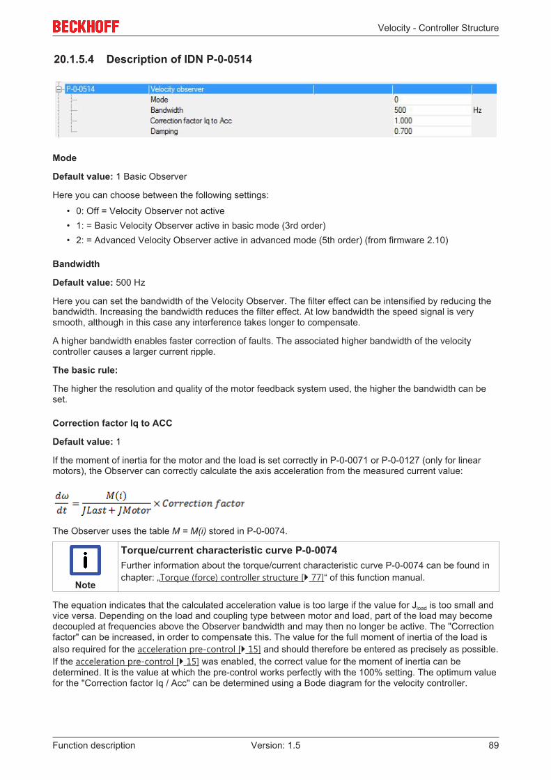
Velocity - Controller Structure
Function description 89Version: 1.5
20.1.5.4 Description of IDN P-0-0514
Mode
Default value: 1 Basic Observer
Here you can choose between the following settings:
• 0: Off = Velocity Observer not active• 1: = Basic Velocity Observer active in basic mode (3rd order)• 2: = Advanced Velocity Observer active in advanced mode (5th order) (from firmware 2.10)
Bandwidth
Default value: 500 Hz
Here you can set the bandwidth of the Velocity Observer. The filter effect can be intensified by reducing thebandwidth. Increasing the bandwidth reduces the filter effect. At low bandwidth the speed signal is verysmooth, although in this case any interference takes longer to compensate.
A higher bandwidth enables faster correction of faults. The associated higher bandwidth of the velocitycontroller causes a larger current ripple.
The basic rule:
The higher the resolution and quality of the motor feedback system used, the higher the bandwidth can beset.
Correction factor lq to ACC
Default value: 1
If the moment of inertia for the motor and the load is set correctly in P-0-0071 or P-0-0127 (only for linearmotors), the Observer can correctly calculate the axis acceleration from the measured current value:
The Observer uses the table M = M(i) stored in P-0-0074.
Note
Torque/current characteristic curve P-0-0074Further information about the torque/current characteristic curve P-0-0074 can be found inchapter: „Torque (force) controller structure [} 77]“ of this function manual.
The equation indicates that the calculated acceleration value is too large if the value for Jload is too small andvice versa. Depending on the load and coupling type between motor and load, part of the load may becomedecoupled at frequencies above the Observer bandwidth and may then no longer be active. The "Correctionfactor" can be increased, in order to compensate this. The value for the full moment of inertia of the load isalso required for the acceleration pre-control [} 15] and should therefore be entered as precisely as possible.If the acceleration pre-control [} 15] was enabled, the correct value for the moment of inertia can bedetermined. It is the value at which the pre-control works perfectly with the 100% setting. The optimum valuefor the "Correction factor Iq / Acc" can be determined using a Bode diagram for the velocity controller.

Velocity - Controller Structure
Function description90 Version: 1.5
Damping
Default value: 0.7
The value can only be changed in basic mode. The default value of 0.7 should remain unchanged, ifpossible.
20.1.5.5 Velocity Observer parameter description
IDN P-0-0070 (Motor continiuous stall torque)
Standstill torque of the motor (according to data sheet)Unit: newton meter (Nm)
IDN P-0-0071 (Mechanical Motor Data)
Rotor moment of inertia of the motor (from the electronic type plate) and motor-related moment of inertia ofthe load (to be entered by the user).Unit: kgcm²
IDN P-0-0073 (Motor peak torque)
Peak torque of the motor (according to data sheet)Unit: newton meter (Nm)
IDN P-0-0126 (Motor continiuous stall force)
Standstill force of the linear motor (according to data sheet)Unit: Newton (N)
IDN P-0-0127 (Mechanical Linear Motor Data)
Weight of the coil unit of the linear motor (from the electronic type plate) and weight of the load (to beentered by the user).Unit: Kilogram (kg)
IDN P-0-0128 (Motor peak force)
Peak force of the linear motor (according to data sheet)Unit: Newton (N)
IDN S-0-0109 (Motor peak current)
Peak current of the motor (according to data sheet)Unit: ampere (A)
IDN S-0-0111 (Motor continuous stall current)
Standstill current of the motor (according to data sheet)Unit: ampere (A)
20.1.6 Control value limiterThe set value limitation affects the control value of the velocity controller. The limitations are unipolar positive(P-0-0523) and unipolar negative (P-0-0524). The limited control value can be read via P-0-0505.

Velocity - Controller Structure
Function description 91Version: 1.5
20.2 Functionality up to firmware v2.06
Note
Description of the function blocksAll firmware v2.06 function blocks that were not described specifically (lower diagram) areidentical to the function blocks of the block diagram for firmware v2.10.
This results in the following relationship for the velocity:
Parameter P-0-0519 contains the result of the differentiation of the position signal. It has the same units asparameter S-0-0040. The origin of parameter S-0-0040 depends on the settings in parameter P-0-0514.
20.2.1 Determining the actual velocity value (Velocity Observer)Functionality up to firmware v2.06Up to firmware v2.06 there is a third-order Observer("Basic mode").Above the bandwidth the velocity signal calculatedfrom the position signal is attenuated with 20 dB perdecade.The Observer operates with the cycle of the velocitycontroller (default setting 8 kHz).

Velocity - Controller Structure
Function description92 Version: 1.5
20.3 Parameter description
IDN S-0-0036 (Velocity command value)
In the velocity controller, velocity command values are transferred cyclically from the controller to the servodrive via this parameter. The cycle time is specified in parameter S-0-0001.
Unit: rev/(230ms)
IDN S-0-0037 (Additive velocity command value)
The parameter contains the additive velocity command value. This is cyclically added to parameter S-0-0036(velocity command value), if the controller provides the value.
Unit: rev/(230ms)
IDN S-0-0040 (Velocity feedback value 1)
The parameter contains the actual velocity value. It is determined from the signals of feedback system 1. If aVelocity Observer is active, the signal of feedback system 1 is transferred by the Velocity Observer.
Unit: rev/(230ms)
IDN S-0-0081 (Additiv torque command value)
Pre-control value for acceleration pre-control. This value is added directly to parameter P-0-0505 andindicates a torque based on parameter P-0-0094. The parameter is only used during commissioning of thehigher-level velocity controller (from firmware v2.10).
Unit: per thousand; one-tenth of a per cent (‰)
IDN S-0-0091 (Bipolar velocity limit value)
This parameter limits the velocity command value of the drive. This parameter defines the upper (positive)and lower (negative) limit. The lowest value of all set limits applies.
Unit: rev/(230ms)
Further information on IDN P-0-0514 can be found under: Description of IDN P-0-0514 [} 89].

Axis deceleration ramps
Function description 93Version: 1.5
21 Axis deceleration ramps
DANGER
Serious injuries caused by moving axes!The deceleration ramps of the AX5000 servo drive are purely functional and not suitablefor personal protection purposes!A fault in the drive system may have the following effects:- it may not be possible to enable the functional deceleration ramps;- it may not be possible to bring the axes to a standstill.In other words, the axes may not respond. This could cause serious injury.Before commissioning ensure that all external personal protection measures were applied.
The AX5000 servo drive has functional deceleration ramps, which brake or coast down the connectedmotors in the event of fault.
Both ramps are configured via the parameters:• S-0-0372 (Drive Halt Acceleration Bipolar) and• S-0-0429 (Emergency Stop Deceleration).
When configuring the parameters, the braking energy balance of the whole system has to be taken intoaccount. Mechanical and electrical limits affect the maximum deceleration.
Electrical limits result from:• the available current
The torque available for braking the axes depends on the maximum current limit. This determines theshortest possible deceleration time.
• the capturing of regenerative energy (generated during braking)The energy is initially captured by the DC link. When this is saturated, energy is fed to the internal orexternal brake resistors. The capacity of the internal and/or external brake resistors indicates for howlong the energy returned from the DC link can be converted to heat. This increases the decelerationtime.
Testing the deceleration ramps
During operation the deceleration ramps are activated automatically in the event of an error reaction of thedrive system. To assess these processes, it is necessary to trigger and test the functional ramps manuallyduring commissioning.
Proceed as follows:
Parameter S-0-0327 (Drive Halt Acceleration Bipolar)
• Trigger the manual process via bit 14 „Enable Drive“ in parameter S-0-0134 (master control word).
Parameter S-0-0429 (Emergency Stop Deceleration)
• Trigger the manual process via parameter P-0-0310 (error reaction verification)"Force error reaction: Closed loop ramp".
Note
Further information on axis deceleration rampsSettings and configuration instructions for the deceleration ramps can be found in this man-ual under digital inputs and outputs [} 22] → hardware enable [} 23] and limit switch monitoring [} 24].

Support and Service
Function description94 Version: 1.5
22 Support and ServiceBeckhoff and their partners around the world offer comprehensive support and service, making available fastand competent assistance with all questions related to Beckhoff products and system solutions.
Beckhoff's branch offices and representatives
Please contact your Beckhoff branch office or representative for local support and service on Beckhoffproducts!
The addresses of Beckhoff's branch offices and representatives round the world can be found on her internetpages:http://www.beckhoff.com
You will also find further documentation for Beckhoff components there.
Beckhoff Headquarters
Beckhoff Automation GmbH & Co. KG
Huelshorstweg 2033415 VerlGermany
Phone: +49(0)5246/963-0Fax: +49(0)5246/963-198e-mail: [email protected]
Beckhoff Support
Support offers you comprehensive technical assistance, helping you not only with the application ofindividual Beckhoff products, but also with other, wide-ranging services:
• support• design, programming and commissioning of complex automation systems• and extensive training program for Beckhoff system components
Hotline: +49(0)5246/963-157Fax: +49(0)5246/963-9157e-mail: [email protected]
Beckhoff Service
The Beckhoff Service Center supports you in all matters of after-sales service:
• on-site service• repair service• spare parts service• hotline service
Hotline: +49(0)5246/963-460Fax: +49(0)5246/963-479e-mail: [email protected]