yhk yhk–ecm - york
TRANSCRIPT
NEWLow energy
consumption ECM motors
Cassette Fan Coil Units
YHK
- 01
/11
Cod
. A47
9014
2 C
/01/
11
www.eurovent-certification.comwww.certiflash.com
YHKYHK–ECM
• Fan absorption • Water pressure drop • Sound power
• Heating emission (2 pipe units) at the following conditions: - Entering water temperature +50°C - Entering air temperature +20°C - Waterflowrateasforthecoolingconditions
• Heating emission (4 pipe units) at the following conditions: - Water temperature +70°C E.W.T. +60°C L.W.T. - Entering air temperature +20°C
• Cooling total emission at the following conditions: - Water temperature +7°C E.W.T. +12°C L.W.T. - Entering air temperature +27°C dry bulb +19°C wet bulb
• Cooling sensible emission at the following conditions: - Water temperature +7°C E.W.T. +12°C L.W.T. - Entering air temperature +27°C dry bulb +19°C wet bulb
The descriptions and illustrations provided in this publication are not binding:Johnson Controls reserve the right, whilst maintaining the essential characteristics
of the types described and illustrated, to make, at any time,without the requirement to promptly update this piece of literature,
any changes that it considers useful for the purposeof improvement or for any other manufacturing or commercial requirements.
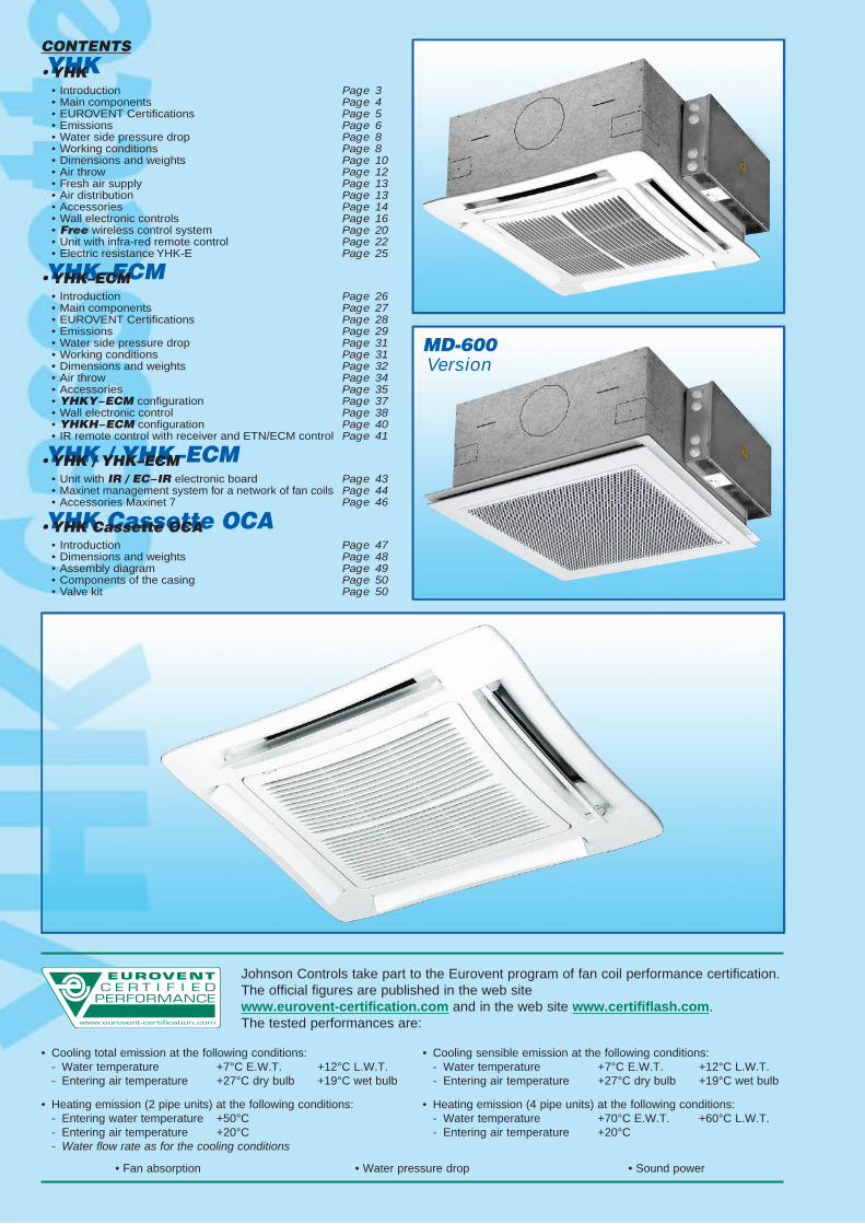
CONTENTS
•YHK • Introduction Page 3 • Main components Page 4 • EUROVENT Certifications Page 5 • Emissions Page 6 • Water side pressure drop Page 8 • Working conditions Page 8 • Dimensions and weights Page 10 • Air throw Page 12 • Fresh air supply Page 13 • Air distribution Page 13 • Accessories Page 14 • Wall electronic controls Page 16 • Freewireless control system Page 20 • Unit with infra-red remote control Page 22 • Electric resistance YHK-E Page 25
•YHK–ECM • Introduction Page 26 • Main components Page 27 • EUROVENT Certifications Page 28 • Emissions Page 29 • Water side pressure drop Page 31 • Working conditions Page 31 • Dimensions and weights Page 32 • Air throw Page 34 • Accessories Page 35 • YHKY−ECMconfiguration Page 37 • Wall electronic control Page 38 • YHKH−ECMconfiguration Page 40 • IR remote control with receiver and ETN/ECM control Page 41
•YHK/YHK–ECM • Unit with IR/EC−IRelectronic board Page 43 • Maxinet management system for a network of fan coils Page 44 • Accessories Maxinet 7 Page 46
•YHKCassetteOCA • Introduction Page 47 • Dimensions and weights Page 48 • Assembly diagram Page 49 • Components of the casing Page 50 • Valve kit Page 50
Johnson Controls take part to the Eurovent program of fan coil performance certification.The official figures are published in the web sitewww.eurovent-certification.com and in the web site www.certififlash.com.The tested performances are:
MD-600Version
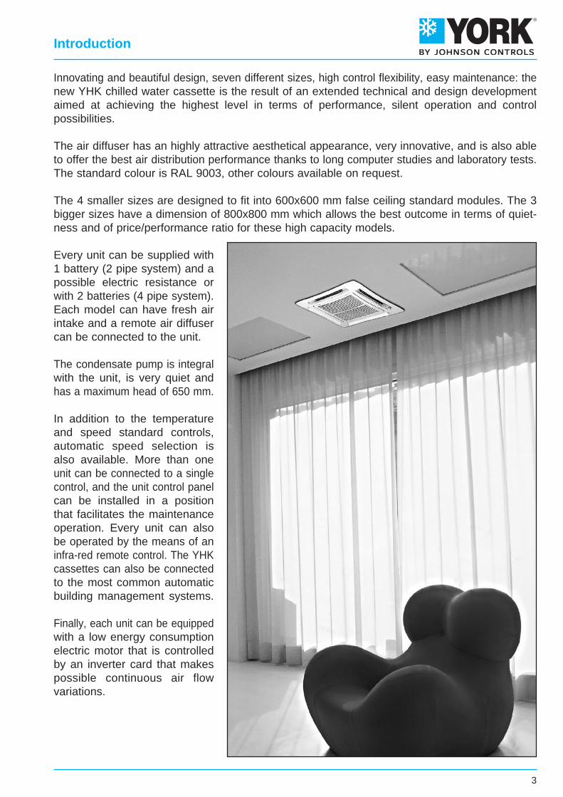
Innovating and beautiful design, seven different sizes, high control flexibility, easy maintenance: thenew YHK chilled water cassette is the result of an extended technical and design developmentaimed at achieving the highest level in terms of performance, silent operation and controlpossibilities.
The air diffuser has an highly attractive aesthetical appearance, very innovative, and is also ableto offer the best air distribution performance thanks to long computer studies and laboratory tests.The standard colour is RAL 9003, other colours available on request.
The 4 smaller sizes are designed to fit into 600x600 mm false ceiling standard modules. The 3bigger sizes have a dimension of 800x800 mm which allows the best outcome in terms of quiet-ness and of price/performance ratio for these high capacity models.
Every unit can be supplied with1 battery (2 pipe system) and apossible electric resistance orwith 2 batteries (4 pipe system).Each model can have fresh airintake and a remote air diffusercan be connected to the unit.
The condensate pump is integralwith the unit, is very quiet andhas a maximum head of 650 mm.
In addition to the temperatureand speed standard controls,automatic speed selection isalso available. More than oneunit can be connected to a singlecontrol, and the unit control panelcan be installed in a positionthat facilitates the maintenanceoperation. Every unit can alsobe operated by the means of aninfra-red remote control. The YHKcassettes can also be connectedto the most common automaticbuilding management systems.
Finally, each unit can be equippedwith a low energy consumptionelectric motor that is controlledby an inverter card that makespossible continuous air flowvariations.
3
Introduction
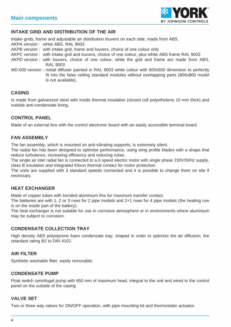
INTAKE GRID AND DISTRIBUTION OF THE AIR
Intake grids, frame and adjustable air distribution louvers on each side, made from ABS.AKPA version : white ABS, RAL 9003AKPB version : with intake grid, frame and louvers, choice of one colour onlyAKPC version : with intake grid and louvers, choice of one colour, plus white ABS frame RAL 9003AKPD version : with louvers, choice of one colour, while the grid and frame are made from ABS, RAL 9003MD-600 version : metal diffuser painted in RAL 9003 white colour with 600x600 dimension to perfectly fit into the false ceiling standard modules without overlapping parts (800x800 model is not available).
CASING
Is made from galvanized steel with inside thermal insulation (closed cell polyethelene 10 mm thick) andoutside anti-condensate lining.
CONTROL PANEL
Made of an external box with the control electronic board with an easily accessible terminal board.
FAN ASSEMBLY
The fan assembly, which is mounted on anti-vibrating supports, is extremely silent.The radial fan has been designed to optimise performance, using wing profile blades with a shape thatreduce turbulence, increasing efficiency and reducing noise.The single air inlet radial fan is connected to a 6 speed electric motor with single phase 230V/50Hz supply,class B insulation and integrated Klixon thermal contact for motor protection.The units are supplied with 3 standard speeds connected and it is possible to change them on site ifnecessary.
HEAT EXCHANGER
Made of copper tubes with bonded aluminium fins for maximum transfer contact.The batteries are with 1, 2 or 3 rows for 2 pipe models and 2+1 rows for 4 pipe models (the heating rowis on the inside part of the battery).The heat exchanger is not suitable for use in corrosive atmosphere or in environments where aluminiummay be subject to corrosion.
CONDENSATE COLLECTION TRAY
High density ABS polystyrene foam condensate tray, shaped in order to optimize the air diffusion, fireretardant rating B2 to DIN 4102.
AIR FILTER
Synthetic washable filter, easily removable.
CONDENSATE PUMP
Float switch centrifugal pump with 650 mm of maximum head, integral to the unit and wired to the controlpanel on the outside of the casing.
VALVE SET
Two or three way valves for ON/OFF operation, with pipe mounting kit and thermostatic actuator.
4
Main components
7104,523,2577710,36,4555511,5342542
0,18
12806,935,18119222,19,9885825,3483995
0,42
18208,896,84152934,7
12,70109238,85849
1700,74
1 2 3
3,01,4
575 x 575 x 275 820 x 820 x 303
3101,511,152606,01,961696,5332425
0,11
4201,961,5533710,02,5421910,5403132
0,15
6102,331,9040113,53,0326114,5494057
0,27
3101,851,343184,62,432095,7332425
0,11
4202,361,714066,93,022608,5403132
0,15
5202,701,984648,83,4629810,8453644
0,20
3201,851,343184,62,432095,7332425
0,11
5002,651,984568,83,4629810,8453644
0,20
7103,342,5657413,44,4037816,6534468
0,32
4302,361,754067,23,102678,8413232
0,15
6103,022,2951911,23,9734113,8494057
0,27
8803,812,9765517,04,9542620,5595090
0,45
SpeedAir flow m3/hCooling total emission kWCooling sensible emission kWWater flow l/h∆P Cooling kPaHeating kWWater flow l/h∆P Heating kPaSound power Lw dB(A)Sound pressure Lp dB(A)
WA
Cooling water content lHeating water content lDimensions mm
Fan
1 2 3 1 2 3 1 2 3 1 2 3
1,00,6
1,40,7
1,40,7
1,40,7
MODEL
6304,142,967128,85,915089,8332433
0,15
8205,033,6586512,57,1961814,0403148
0,23
11406,344,69109018,99,1078321,4483977
0,36
7104,523,2577710,36,4555511,5342542
0,18
9705,664,1597415,48,1069717,4403163
0,28
15007,715,83132626,911,0094629,953441200,53
1 2 3 1 2 3
3,01,4
3,01,4
YHK 110-4YHK 20-4 YHK 25-4 YHK 40-4 YHK 50-4 YHK 65-4 YHK 95-4
3101,841,352,223164,94,1332425
0,11
4202,341,752,904027,66,3403132
0,15
5202,682,043,354619,78,2453644
0,20
3202,251,572,563874,63,5332425
0,11
5003,342,393,935749,47,3453644
0,20
7104,333,185,2374515,111,4534468
0,32
4302,942,083,435067,56,7413232
0,15
6103,882,814,6366712,411,2494057
0,27
8805,023,746,1786319,717,7595090
0,45
6304,213,035,1272410,96,7332433
0,15
8204,913,586,0384514,39,9403148
0,23
11406,164,597,77106021,615,1483977
0,36
7105,313,465,619139,47,9342542
0,18
9706,784,487,34116614,712,4403163
0,28
15009,516,4810,71163626,923,053441200,53
7105,313,716,139139,47,9342542
0,18
12808,456,09
10,30145321,818,6483995
0,42
182011,108,25
14,00190935,630,65849
1700,74
3101,271,011,622194,54,0332425
0,11
4201,631,322,122807,06,0403132
0,15
6101,981,642,6434010,09,0494057
0,27
1 2 3 1 2 3 1 2 3 1 2 3 1 2 3 1 2 31 2 3
1,4 3,0 4,02,1 2,1 4,00,8820 x 820 x 303575 x 575 x 275
SpeedAir flow m3/hCooling total emission kWCooling sensible emission kWHeating kWWater flow l/h∆P Cooling kPa∆P Heating kPaSound power Lw dB(A)Sound pressure Lp dB(A)
WA
Water content lDimensions mm
MODEL
Fan
YHK 25-2 YHK 40-2 YHK 50-2 YHK 65-2 YHK 95-2 YHK 110-2YHK 20-2
5
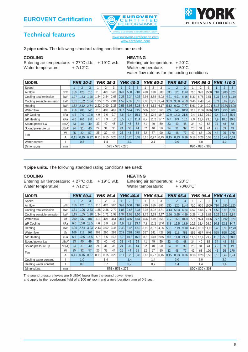
2 pipe units. The following standard rating conditions are used:
COOLINGEntering air temperature: + 27°C d.b., + 19°C w.b.Water temperature: + 7/12°C
HEATINGEntering air temperature: + 20°CWater temperature: + 50°Cwater flow rate as for the cooling conditions
4 pipe units. The following standard rating conditions are used:
COOLINGEntering air temperature: + 27°C d.b., + 19°C w.b.Water temperature: + 7/12°C
HEATINGEntering air temperature: + 20°CWater temperature: + 70/60°C
EUROVENT Certification
Technical features
The sound pressure levels are 9 dB(A) lower than the sound power levelsand apply to the reverberant field of a 100 m3 room and a reverberation time of 0.5 sec.
www.eurovent-certification.comwww.certiflash.com
YHK25-2
YHK20-2
YHK40-2
YHK50-2
YHK65-2
YHK95-2
YHK110-2
386310237482417356787593412903702520
1118865734
16831146876
20151471876
2,241,801,382,802,422,074,573,452,395,254,083,026,505,034,279,786,675,09
11,728,555,09
203164126266232198440334235504394294624486415951655505
1132834505
2,371,911,463,102,692,315,123,892,735,864,583,427,265,654,82
11,067,625,87
13,179,705,87
298239183377327279619467326709552410878681578
1327906694
15861161694
3,462,782,134,393,803,257,195,433,798,256,424,77
10,217,926,72
15,4310,548,07
18,4513,508,07
393315240488422360795598415914709524
1130874741
16991155882
20371484882
4,563,662,805,684,914,199,256,964,83
10,638,256,10
13,1410,168,61
19,7613,4310,2523,6817,2610,25
488391298599513441972730505
1118866639
13831067903
207114031068248618071068
5,674,553,476,975,965,12
11,308,485,87
13,0010,077,43
16,0812,4110,5024,0816,3212,4228,9121,0112,42
610420310520420310710500320880610430
1140820630
1500970710
18201280710
HighMedLowHighMedLowHighMedLowHighMedLowHighMedLowHighMedLow
HighMedLow
Model SpeedAirflow
EWT 45 - LWT 40°C EWT 50 - LWT 40°C EWT 60 - LWT 50°C EWT 70 - LWT 60°C EWT 80 - LWT 70°C
l/hm3/h kW l/h kW l/h kW l/h kW l/h kW
Waterflow Emission
Waterflow Emission
Waterflow Emission
Waterflow Emission
Waterflow Emission
YHK25-2
YHK20-2
YHK40-2
YHK50-2
YHK65-2
YHK95-2
YHK110-2
HighMedLowHighMedLowHighMedLowHighMedLowHighMedLowHighMedLow
HighMedLow
EWT 5 - LWT 10°C EWT 7 - LWT 12°C EWT 9 - LWT 14°C EWT 12 - LWT 17°CWaterflow
Totalemission
Sensibleemission
Waterflow
Totalemission
Sensibleemission
Waterflow
Totalemission
Sensibleemission
Waterflow
Totalemission
Sensibleemission
Model SpeedAirflow
l/h kW kW l/h kW kW l/h kW kW l/h kW kWm3/h610420310520420310710500320880610430
1140820630
1500970710
18201280710
421346269554482417926715508
1049835633
12641003858
194313741070227717221070
2,452,011,573,222,802,425,384,152,956,104,853,687,355,834,99
11,307,996,22
13,2410,016,22
1,831,481,142,221,911,643,642,771,944,173,262,445,003,923,327,595,274,069,016,684,06
340280219462403317745575387863667506
1060845722
16351166913
19091454913
1,981,631,272,682,341,844,333,342,255,023,882,946,164,914,219,516,785,31
11,108,455,31
1,641,321,012,041,751,353,182,391,573,742,812,084,593,583,036,484,483,468,256,093,71
254210165362317276617483349694559430840674580
1301939740
15111162740
1,471,220,962,101,841,613,592,812,034,033,252,504,883,923,377,575,464,308,786,754,30
1,451,160,891,751,501,292,872,181,533,292,571,923,953,092,625,994,153,207,115,273,20
199160123252220188420319225479376283573453384880612434
1044775434
1,160,930,711,471,281,092,441,861,312,792,191,653,332,632,235,123,562,526,074,512,52
1,160,930,711,471,281,092,441,861,312,792,191,653,332,632,235,123,562,526,074,512,52
7/12 °C10/15 °C14/18 °C
KKK
0,90,720,5
0,940,780,58
1,060,9
0,72
7/12 °C10/15 °C14/18 °C
KKK
0,820,560,35
0,890,630,41
1,110,820,52
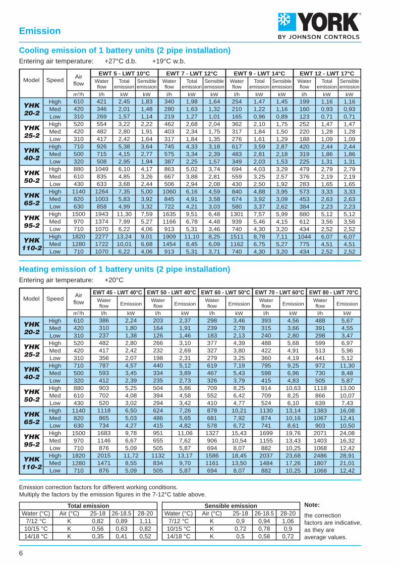
Water (°C) Air (°C) 25-18 26-18.5 28-20 Water (°C) Air (°C) 25-18 26-18.5 28-20Total emission Sensible emission Note:
the correctionfactors are indicative,as they areaverage values.
Emission correction factors for different working conditions.Multiply the factors by the emission figures in the 7-12°C table above.
6
Cooling emission of 1 battery units (2 pipe installation)Entering air temperature: +27°C d.b. +19°C w.b.
Emission
Heating emission of 1 battery units (2 pipe installation)Entering air temperature: +20°C
YHK25-4
YHK20-4
YHK40-4
YHK50-4
YHK65-4
YHK95-4
YHK110-4
Model SpeedAirflow
EWT 45 - LWT 40°C EWT 50 - LWT 40°C EWT 60 - LWT 50°C EWT 70 - LWT 60°C EWT 80 - LWT 70°C
l/hm3/h kW l/h kW l/h kW l/h kW l/h kW
Waterflow Emission
Waterflow Emission
Waterflow Emission
Waterflow Emission
Waterflow Emission
256215166283247196351277196402317247771609501929686547
1074845547
1,491,250,961,651,441,142,041,611,142,341,841,444,483,542,915,403,993,186,244,913,18
13411387
149130103184146103211166130410324267493365291569449291
1,561,311,011,731,511,202,141,691,202,451,941,514,763,773,115,734,253,396,615,223,39
197166128218191151270214151310244191596471388718531423829653423
2,291,931,492,542,221,763,142,481,763,602,842,226,935,484,518,346,174,929,647,604,92
261219169298260209378298209426341267783618508946697555
1092858555
3,032,541,963,463,022,434,403,462,434,953,973,109,107,195,91
11,008,106,45
12,709,986,45
325272210358312247444350247510401312970766629
1170864686
13531064686
3,783,172,444,173,632,875,174,072,875,934,673,63
11,288,907,31
13,6010,047,98
15,7412,377,98
610420310520420310710500320880610430
1140820630
1500970710
18201280710
HighMedLowHighMedLowHighMedLowHighMedLowHighMedLowHighMedLow
HighMedLow
YHK25-4
YHK20-4
YHK40-4
YHK50-4
YHK65-4
YHK95-4
YHK110-4
HighMedLowHighMedLowHighMedLowHighMedLowHighMedLowHighMedLow
HighMedLow
490410314569465398718569398791632510
12991027842
15881158920
18361423920
2,852,381,823,312,712,314,183,312,314,603,672,977,555,974,899,236,735,35
10,678,275,35
2,121,731,292,261,831,552,912,261,553,232,532,015,124,003,246,354,533,567,435,643,56
401337260465405318574455318656520405
1090866713
1327974778
15291191778
2,331,961,512,702,361,853,342,651,853,813,022,366,345,034,147,715,664,528,896,934,52
1,901,551,151,981,701,342,561,981,342,972,291,754,693,652,965,834,153,256,845,183,25
307260201374309267467374267512413337864691572
1046775623
1199942623
1,781,511,172,181,801,552,722,181,552,982,401,965,024,023,336,084,503,626,975,483,62
1,691,371,021,791,441,222,301,791,222,562,001,594,043,152,565,023,572,815,984,462,81
2391961482602101773302601773662882315864623747,26524411849646411
1,391,140,861,511,221,031,921,511,032,131,671,353,412,682,174,223,052,394,943,752,39
1,391,140,861,511,221,031,921,511,032,131,671,353,412,682,174,223,052,394,943,752,39
610420310520420310710500320880610430
1140820630
1500970710
18201280710
EWT 5 - LWT 10°C EWT 7 - LWT 12°C EWT 9 - LWT 14°C EWT 12 - LWT 17°CWaterflow
Totalemission
Sensibleemission
Waterflow
Totalemission
Sensibleemission
Waterflow
Totalemission
Sensibleemission
Waterflow
Totalemission
Sensibleemission
Model SpeedAirflow
l/h kW kW l/h kW kW l/h kW kW l/h kW kWm3/h
7/12 °C10/15 °C14/18 °C
KKK
0,90,720,5
0,940,780,58
1,060,9
0,72
7/12 °C10/15 °C14/18 °C
KKK
0,820,560,35
0,890,630,41
1,110,820,52
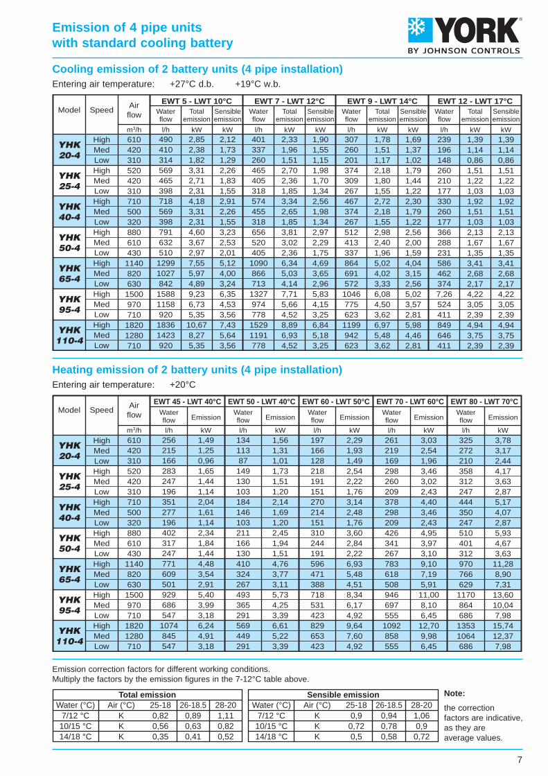
Water (°C) Air (°C) 25-18 26-18.5 28-20 Water (°C) Air (°C) 25-18 26-18.5 28-20Total emission Sensible emission Note:
the correctionfactors are indicative,as they areaverage values.
7
Emission correction factors for different working conditions.Multiply the factors by the emission figures in the 7-12°C table above.
Cooling emission of 2 battery units (4 pipe installation)Entering air temperature: +27°C d.b. +19°C w.b.
Heating emission of 2 battery units (4 pipe installation)Entering air temperature: +20°C
Emission of 4 pipe unitswith standard cooling battery
Pre
ssur
e dr
op (
kPa)
Water flow (l/h)
Pre
ssur
e dr
op (
kPa)
Water flow (l/h)
Pre
ssur
e dr
op (
kPa)
Water flow (l/h)
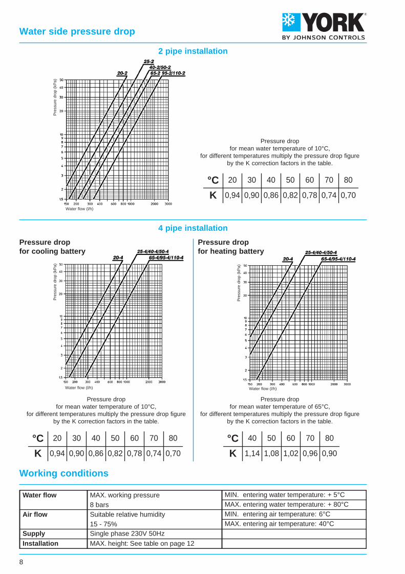
Water flow
Air flow
Supply
MAX. working pressure8 barsSuitable relative humidity15 - 75%Single phase 230V 50Hz
MIN. entering water temperature: + 5°CMAX. entering water temperature: + 80°CMIN. entering air temperature: 6°CMAX. entering air temperature: 40°C
Installation MAX. height: See table on page 12
°CK
20
0,94
30
0,90
40
0,86
50
0,82
60
0,78
70
0,74
80
0,70
°CK
20
0,94
30
0,90
40
0,86
50
0,82
60
0,78
70
0,74
80
0,70
°CK
40
1,14
50
1,08
60
1,02
70
0,96
80
0,90
Pressure dropfor mean water temperature of 10°C,
for different temperatures multiply the pressure drop figureby the K correction factors in the table.
Pressure dropfor mean water temperature of 65°C,
for different temperatures multiply the pressure drop figureby the K correction factors in the table.
Working conditions
Pressure dropfor mean water temperature of 10°C,
for different temperatures multiply the pressure drop figureby the K correction factors in the table.
Pressure dropfor cooling battery
Pressure dropfor heating battery
2 pipe installation
4 pipe installation
8
Water side pressure drop
9
NOTES
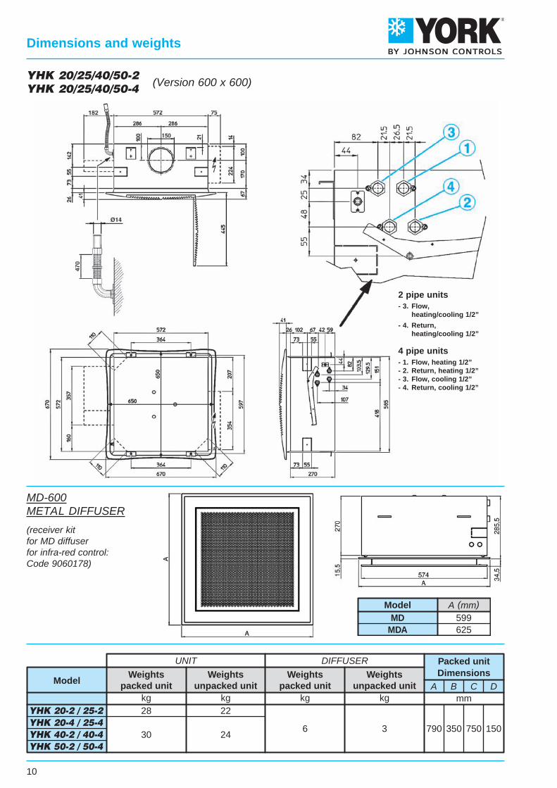
790 350 750 150
A B C Dmm
30 246 3
kg kg
Weightspacked unit
Weightsunpacked unit
YHK 20-2 / 25-2 YHK 20-4 / 25-4 YHK 40-2 / 40-4 YHK 50-2 / 50-4
28 22
UNIT DIFFUSER
kg kg
ModelWeights
packed unitWeights
unpacked unit
Packed unitDimensions
MD-600METAL DIFFUSER
(receiver kitfor MD diffuserfor infra-red control:Code 9060178)
YHK 20/25/40/50-2YHK 20/25/40/50-4
10
Dimensions and weights
(Version 600 x 600)
2 pipe units- 3. Flow, heating/cooling 1/2”
- 4. Return, heating/cooling 1/2”
4 pipe units- 1. Flow, heating 1/2”- 2. Return, heating 1/2”- 3. Flow, cooling 1/2”- 4. Return, cooling 1/2”
A (mm)MD
MDA599625
Model
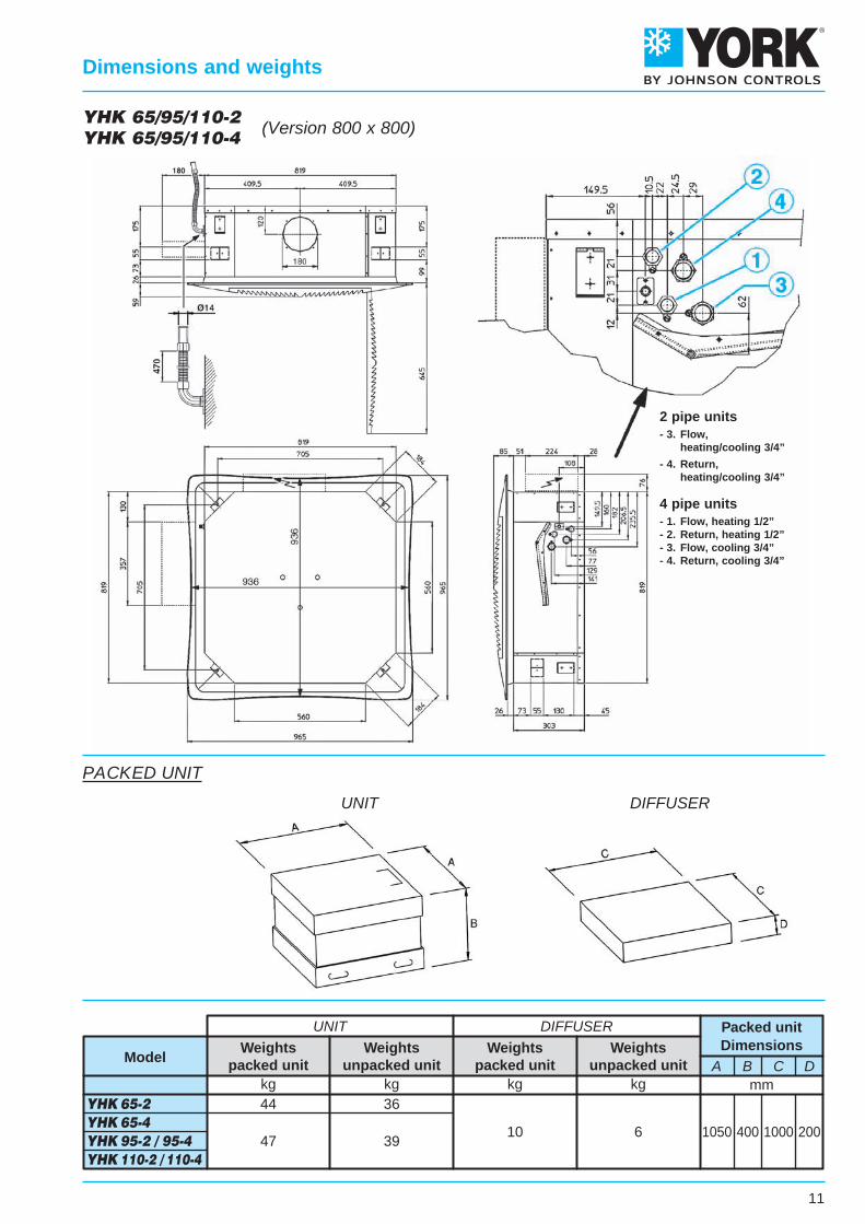
Packed unitDimensions
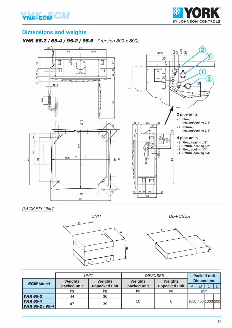
1050 400 1000 200
A B C Dmm
47 3910 6
kg kg
Weightspacked unit
Weightsunpacked unit
YHK 65-2 YHK 65-4 YHK 95-2 / 95-4 YHK 110-2 / 110-4
44 36
UNIT DIFFUSER
kg kg
ModelWeights
packed unitWeights
unpacked unit
UNIT DIFFUSER
PACKED UNIT
11
Dimensions and weights
YHK 65/95/110-2YHK 65/95/110-4 (Version 800 x 800)
2 pipe units- 3. Flow, heating/cooling 3/4”
- 4. Return, heating/cooling 3/4”
4 pipe units- 1. Flow, heating 1/2”- 2. Return, heating 1/2”- 3. Flow, cooling 3/4”- 4. Return, cooling 3/4”
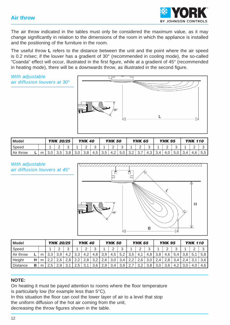
1 2 3 1 2 3 1 2 3 1 2 3 1 2 3 1 2 33,32,22,5
3,92,62,9
4,22,83,1
3,32,22,5
4,22,83,1
4,83,23,6
3,92,62,9
4,53,03,4
5,23,43,9
3,52,22,7
4,12,63,2
4,83,03,8
3,82,43,0
4,62,83,6
5,43,44,2
3,82,43,0
5,13,14,0
5,83,64,6
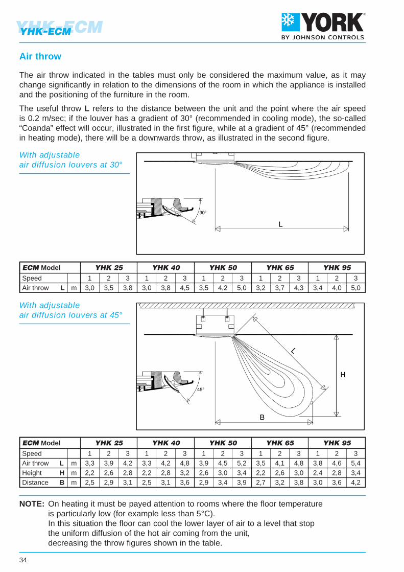
SpeedAir throw L mHeight H mDistance B m
Model YHK 20/25 YHK 40 YHK 50 YHK 65 YHK 95 YHK 110
YHK 20/25 YHK 40 YHK 50 YHK 65 YHK 95 YHK 110SpeedAir throw L m
1 2 3 1 2 3 1 2 3 1 2 3 1 2 3 1 2 33,0 3,5 3,8 3,0 3,8 4,5 3,5 4,2 5,0 3,2 3,7 4,3 3,4 4,0 5,0 3,4 4,6 5,5
Model
NOTE:On heating it must be payed attention to rooms where the floor temperatureis particularly low (for example less than 5°C).In this situation the floor can cool the lower layer of air to a level that stopthe uniform diffusion of the hot air coming from the unit,decreasing the throw figures shown in the table.
The air throw indicated in the tables must only be considered the maximum value, as it maychange significantly in relation to the dimensions of the room in which the appliance is installedand the positioning of the furniture in the room.
The useful throw L refers to the distance between the unit and the point where the air speedis 0.2 m/sec; if the louver has a gradient of 30° (recommended in cooling mode), the so-called“Coanda” effect will occur, illustrated in the first figure, while at a gradient of 45° (recommendedin heating mode), there will be a downwards throw, as illustrated in the second figure.
With adjustableair diffusion louvers at 30°
12
Air throw
With adjustableair diffusion louvers at 45°
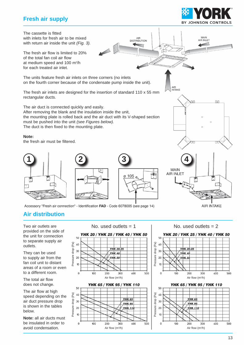
The cassette is fittedwith inlets for fresh air to be mixedwith return air inside the unit (Fig. 3).
The fresh air flow is limited to 20%of the total fan coil air flowat medium speed and 100 m3/hfor each treated air inlet.
The units feature fresh air inlets on three corners (no inletson the fourth corner because of the condensate pump inside the unit).
The fresh air inlets are designed for the insertion of standard 110 x 55 mmrectangular ducts.
The air duct is connected quickly and easily.After removing the blank and the insulation inside the unit,the mounting plate is rolled back and the air duct with its V-shaped sectionmust be pushed into the unit (see Figures below).The duct is then fixed to the mounting plate.
Note:the fresh air must be filtered.
Two air outlets areprovided on the side ofthe unit for connectionto separate supply airoutlets.
They can be usedto supply air from thefan coil unit to distantareas of a room or evento a different room.
The total air flowdoes not change.
The air flow at highspeed depending on theair duct pressure dropis shown in the tablesbelow.
Note: all air ducts mustbe insulated in order toavoid condensation.
Air distribution
13
Fresh air supply
1 2 3 4
No. used outlets = 1 No. used outlets = 2
Air flow (m3/h)
Air flow (m3/h)
Air flow (m3/h)
Air flow (m3/h)
Pre
ssur
e dr
op (
Pa)
Pre
ssur
e dr
op (
Pa)
Pre
ssur
e dr
op (
Pa)
Pre
ssur
e dr
op (
Pa)
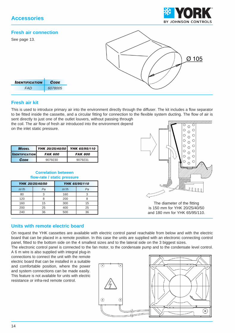
Units with remote electric boardOn request the YHK cassettes are available with electric control panel reachable from below and with the electricboard that can be placed in a remote position. In this case the units are supplied with an electronic connecting controlpanel, fitted to the bottom side on the 4 smallest sizes and to the lateral side on the 3 biggest sizes.The electronic control panel is connected to the fan motor, to the condensate pump and to the condensate level control.A 6 m wire is also supplied with integral plug-inconnections to connect the unit with the remoteelectric board that can be installed in a suitableand comfortable position, where the powerand system connections can be made easily.This feature is not available for units with electricresistance or infra-red remote control.
14
Accessories
Fresh air connectionSee page 13.
IdentIfIcatIon code
FAD 6078005
Fresh air kitThis is used to introduce primary air into the environment directly through the diffuser. The kit includes a flow separatorto be fitted inside the cassette, and a circular fitting for connection to the flexible system ducting. The flow of air issent directly to just one of the outlet louvers, without passing throughthe coil. The air flow of fresh air introduced into the environment dependon the inlet static pressure.
The diameter of the fittingis 150 mm for YHK 20/25/40/50and 180 mm for YHK 65/95/110.
faK 800
YHK 65/95/110
9079231
faK 600
YHK 20/25/40/50
9079230
IdentIfIcatIon
Model
code
Correlation betweenflow-rate / static pressure
YHK 20/25/40/50 YHK 65/95/110
160200300400500
80120160200240
m3/hm3/h
38
152536
38
152536
PaPa
15
Accessories
* maximum pressure difference for valve to close ** external thread, flat seal
Batterytype
Main
Model
Auxiliary
20/25/40/50-2
20/25/40/50-4
65/95/110-2
65/95/110-4
20/25/40/50-4
65/95/110-4
2 way valves 3 way valves
Kvs
m3/h∆pmax
kPa *Valve **
connectionKvs
m3/h∆pmax
kPa *Valve **
connection
2,8
5,2
2,8
50
60
50
3/4"
1"
3/4"
2,5
4,5
2,5
50
50
50
3/4"
1"
3/4"
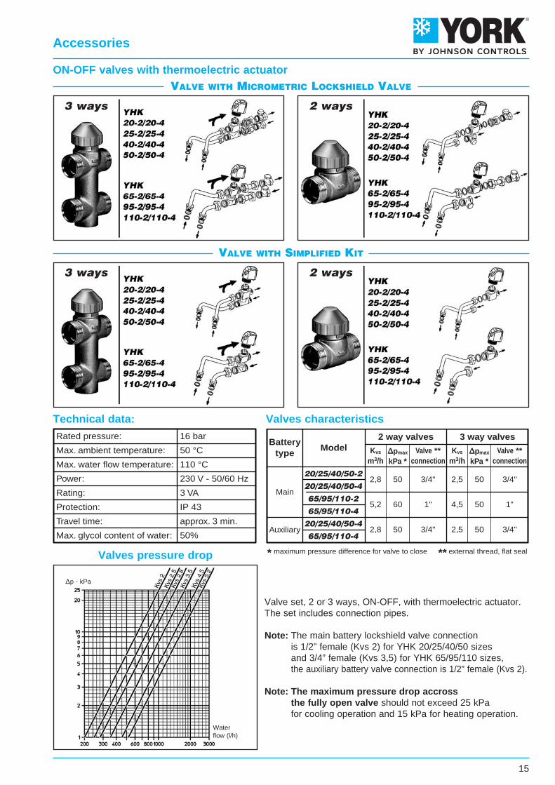
Rated pressure:
Max. ambient temperature:
Max. water flow temperature:
Power:
Rating:
Protection:
Travel time:
Max. glycol content of water:
16 bar
50 °C
110 °C
230 V - 50/60 Hz
3 VA
IP 43
approx. 3 min.
50%
ON-OFF valves with thermoelectric actuator
Valve set, 2 or 3 ways, ON-OFF, with thermoelectric actuator.The set includes connection pipes.
Note: The main battery lockshield valve connection is 1/2” female (Kvs 2) for YHK 20/25/40/50 sizes and 3/4” female (Kvs 3,5) for YHK 65/95/110 sizes, the auxiliary battery valve connection is 1/2” female (Kvs 2).
Note: The maximum pressure drop accross the fully open valve should not exceed 25 kPa for cooling operation and 15 kPa for heating operation.
Technical data: Valves characteristics
3 ways 2 ways
Valves pressure drop
3 ways 2 ways
ValVe with MicroMetric lockshield ValVe
ValVe with siMplified kit
Waterflow (l/h)
∆p - kPa
16
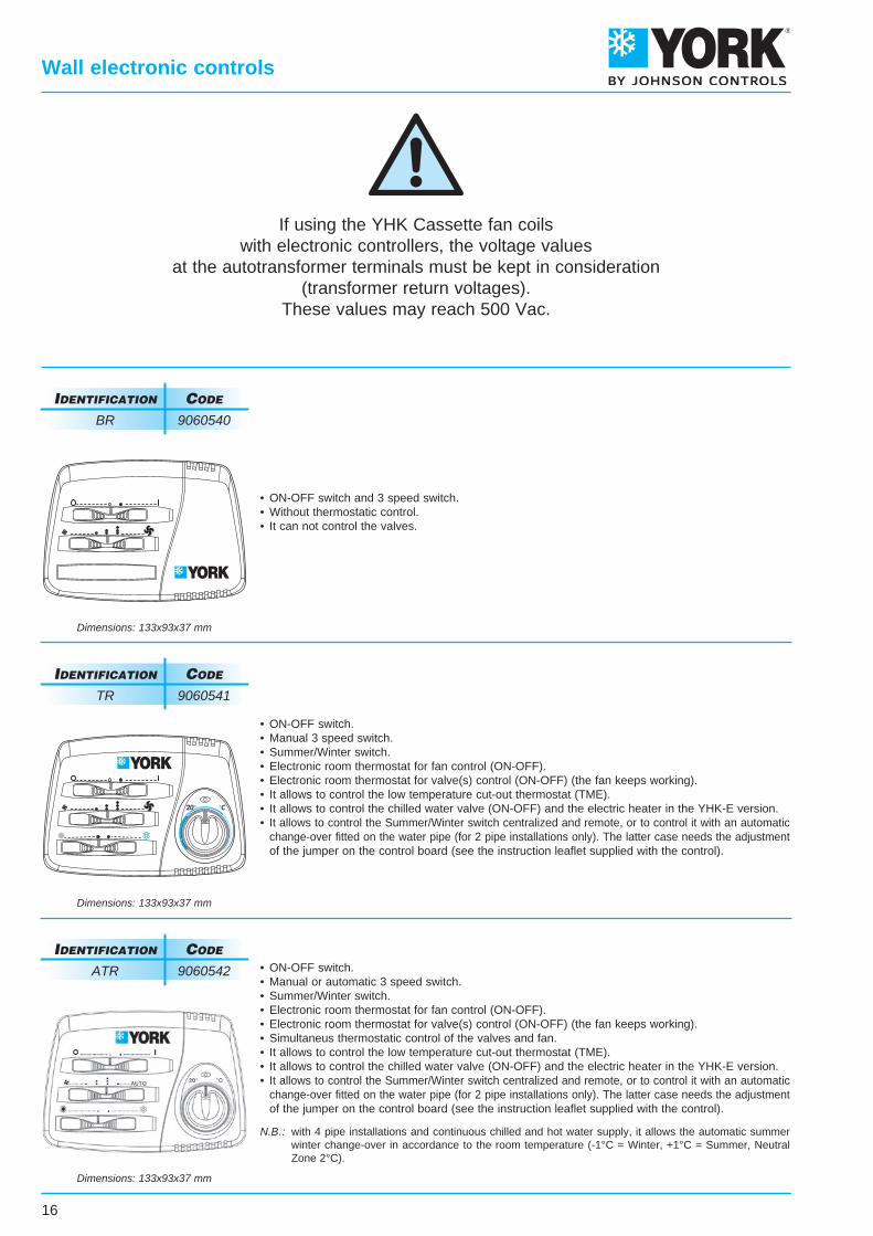
Wall electronic controls
If using the YHK Cassette fan coilswith electronic controllers, the voltage values
at the autotransformer terminals must be kept in consideration(transformer return voltages).
These values may reach 500 Vac.
• ON-OFF switch.• Manual or automatic 3 speed switch.• Summer/Winter switch.• Electronic room thermostat for fan control (ON-OFF).• Electronic room thermostat for valve(s) control (ON-OFF) (the fan keeps working).• Simultaneus thermostatic control of the valves and fan.• It allows to control the low temperature cut-out thermostat (TME).• It allows to control the chilled water valve (ON-OFF) and the electric heater in the YHK-E version.• It allows to control the Summer/Winter switch centralized and remote, or to control it with an automatic change-over fitted on the water pipe (for 2 pipe installations only). The latter case needs the adjustment of the jumper on the control board (see the instruction leaflet supplied with the control).
N.B.: with 4 pipe installations and continuous chilled and hot water supply, it allows the automatic summer winter change-over in accordance to the room temperature (-1°C = Winter, +1°C = Summer, Neutral Zone 2°C).
IdentIfIcatIon code
ATR 9060542
Dimensions: 133x93x37 mm
• ON-OFF switch.• Manual 3 speed switch.• Summer/Winter switch.• Electronic room thermostat for fan control (ON-OFF).• Electronic room thermostat for valve(s) control (ON-OFF) (the fan keeps working).• It allows to control the low temperature cut-out thermostat (TME).• It allows to control the chilled water valve (ON-OFF) and the electric heater in the YHK-E version.• It allows to control the Summer/Winter switch centralized and remote, or to control it with an automatic change-over fitted on the water pipe (for 2 pipe installations only). The latter case needs the adjustment of the jumper on the control board (see the instruction leaflet supplied with the control).
IdentIfIcatIon code
TR 9060541
Dimensions: 133x93x37 mm
• ON-OFF switch and 3 speed switch.• Without thermostatic control.• It can not control the valves.
IdentIfIcatIon code
BR 9060540
Dimensions: 133x93x37 mm
17
Wall electronic controls
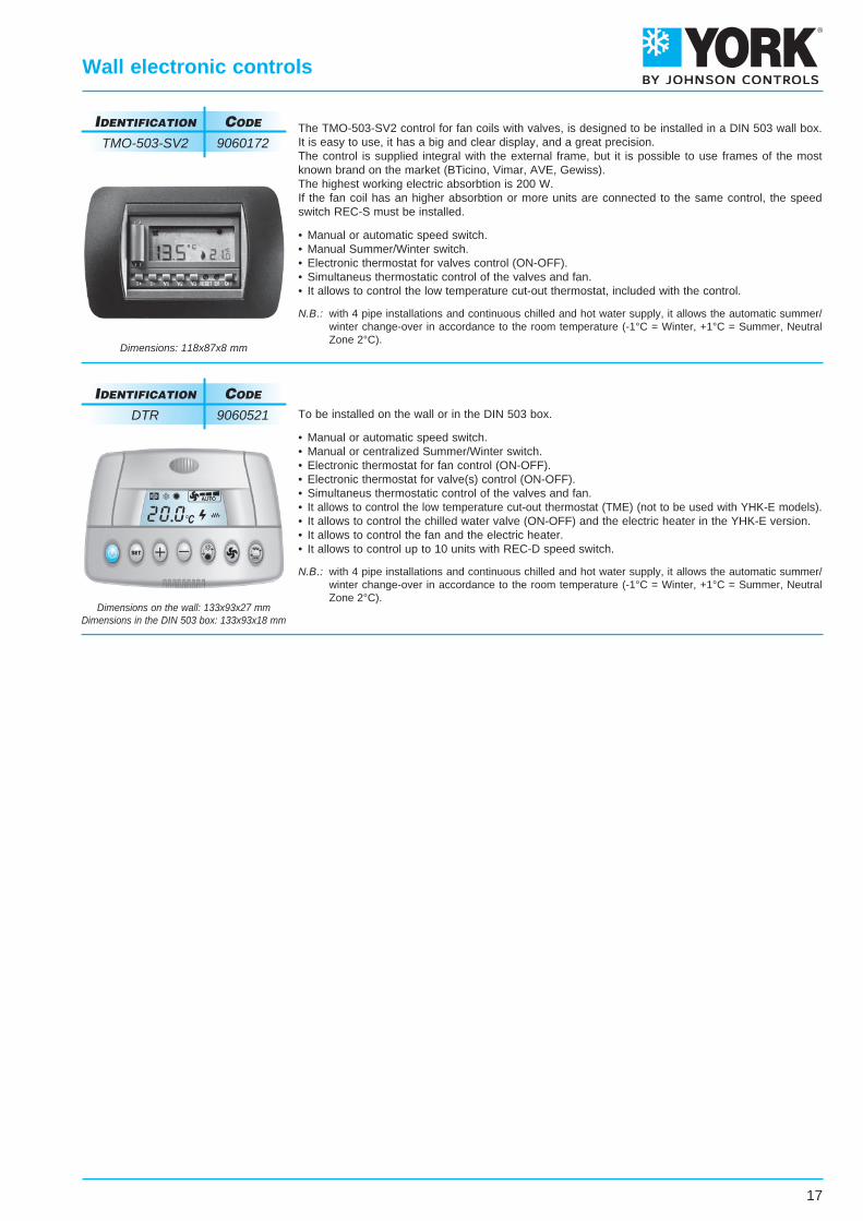
To be installed on the wall or in the DIN 503 box.
• Manual or automatic speed switch.• Manual or centralized Summer/Winter switch.• Electronic thermostat for fan control (ON-OFF).• Electronic thermostat for valve(s) control (ON-OFF).• Simultaneus thermostatic control of the valves and fan.• It allows to control the low temperature cut-out thermostat (TME) (not to be used with YHK-E models).• It allows to control the chilled water valve (ON-OFF) and the electric heater in the YHK-E version.• It allows to control the fan and the electric heater.• It allows to control up to 10 units with REC-D speed switch.
N.B.: with 4 pipe installations and continuous chilled and hot water supply, it allows the automatic summer/ winter change-over in accordance to the room temperature (-1°C = Winter, +1°C = Summer, Neutral Zone 2°C).
IdentIfIcatIon code
DTR 9060521
Dimensions on the wall: 133x93x27 mmDimensions in the DIN 503 box: 133x93x18 mm
The TMO-503-SV2 control for fan coils with valves, is designed to be installed in a DIN 503 wall box.It is easy to use, it has a big and clear display, and a great precision.The control is supplied integral with the external frame, but it is possible to use frames of the mostknown brand on the market (BTicino, Vimar, AVE, Gewiss).The highest working electric absorbtion is 200 W.If the fan coil has an higher absorbtion or more units are connected to the same control, the speedswitch REC-S must be installed.
• Manual or automatic speed switch.• Manual Summer/Winter switch.• Electronic thermostat for valves control (ON-OFF).• Simultaneus thermostatic control of the valves and fan.• It allows to control the low temperature cut-out thermostat, included with the control.
N.B.: with 4 pipe installations and continuous chilled and hot water supply, it allows the automatic summer/ winter change-over in accordance to the room temperature (-1°C = Winter, +1°C = Summer, Neutral Zone 2°C).
IdentIfIcatIon code
TMO-503-SV2 9060172
Dimensions: 118x87x8 mm
RED
BLACK
18
Speed switches
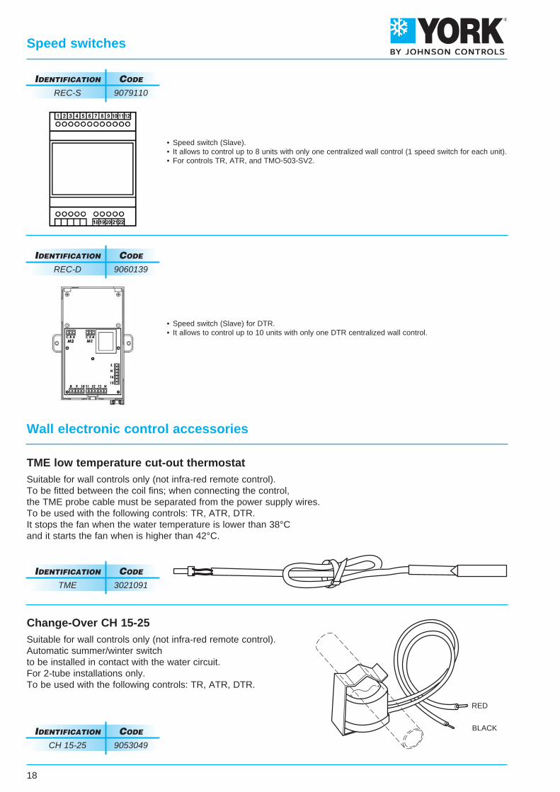
TME low temperature cut-out thermostatSuitable for wall controls only (not infra-red remote control).To be fitted between the coil fins; when connecting the control,the TME probe cable must be separated from the power supply wires.To be used with the following controls: TR, ATR, DTR.It stops the fan when the water temperature is lower than 38°Cand it starts the fan when is higher than 42°C.
Change-Over CH 15-25Suitable for wall controls only (not infra-red remote control).Automatic summer/winter switchto be installed in contact with the water circuit.For 2-tube installations only.To be used with the following controls: TR, ATR, DTR.
IdentIfIcatIon code
CH 15-25 9053049
IdentIfIcatIon code
TME 3021091
• Speed switch (Slave).• It allows to control up to 8 units with only one centralized wall control (1 speed switch for each unit).• For controls TR, ATR, and TMO-503-SV2.
IdentIfIcatIon code
REC-S 9079110
• Speed switch (Slave) for DTR.• It allows to control up to 10 units with only one DTR centralized wall control.
IdentIfIcatIon code
REC-D 9060139
Wall electronic control accessories
co
nt
Ro
l c
od
eS
co
nt
Ro
lo
Pe
Ra
tIo
nS
co
nt
Ro
lId
en
tIf
Ica
tIo
nDTR
TMO-503-SV2
ATR
TR
BR
9060521
9060172
9060542
9060541
9060540
Inst
alla
tion
of e
lect
roni
c lo
w t
empe
ratu
re C
UT
-OU
T t
herm
osta
t (T
ME
)
Roo
m t
herm
osta
t fo
r fa
n an
d el
ectr
ic h
eate
r co
ntro
l
Roo
m t
herm
osta
t fo
r ch
illed
wat
er v
alve
(S
UM
ME
R)
and
elec
tric
hea
ter
(WIN
TE
R)
cont
rol
(in w
inte
r on
ly t
he e
lect
ric h
eate
r is
wor
king
)
Sim
ulta
neou
s th
erm
osta
tic c
ontr
ol o
f th
e va
lves
and
fan
Roo
m t
herm
osta
t fo
r 2
valv
e co
ntro
l (4
pipe
inst
alla
tion)
Roo
m t
herm
osta
t fo
r 1
valv
e co
ntro
l (2
pipe
inst
alla
tion)
Roo
m t
herm
osta
t fo
r fa
n co
ntro
l (O
N-O
FF
)
Aut
omat
ic S
umm
er/W
inte
r sw
itch
with
neu
tral
zon
e fo
r 4
pipe
inst
alla
tion
with
2 v
alve
s
Rem
ote
cent
raliz
ed S
umm
er/W
inte
r sw
itch
or b
y an
aut
omat
ic c
hang
e-ov
er f
itted
on
the
wat
er p
ipe
Sum
mer
/Win
ter
switc
h
Man
ual/A
utom
atic
3 s
peed
sel
ectio
n
Man
ual 3
spe
ed s
witc
h
ON
-OF
F s
witc
h fo
r th
e el
ectr
ic h
eate
r
ON
-OF
F s
witc
h
19
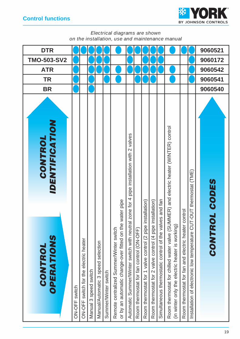
Control functions
Electrical diagrams are shownon the installation, use and maintenance manual
20
Free wireless control system
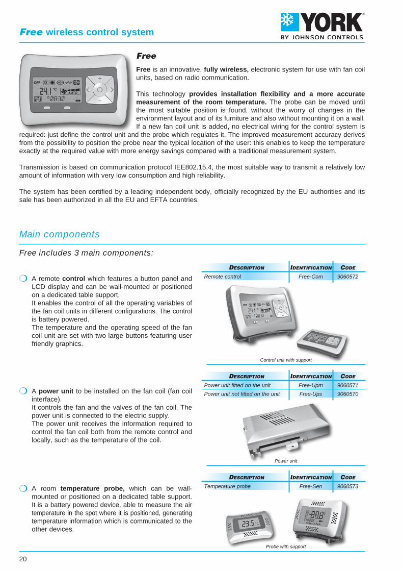
Free
Free is an innovative, fully wireless, electronic system for use with fan coilunits, based on radio communication.
This technology provides installation flexibility and a more accuratemeasurement of the room temperature. The probe can be moved untilthe most suitable position is found, without the worry of changes in theenvironment layout and of its furniture and also without mounting it on a wall.If a new fan coil unit is added, no electrical wiring for the control system is
required: just define the control unit and the probe which regulates it. The improved measurement accuracy derivesfrom the possibility to position the probe near the typical location of the user: this enables to keep the temperatureexactly at the required value with more energy savings compared with a traditional measurement system.
Transmission is based on communication protocol IEE802.15.4, the most suitable way to transmit a relatively lowamount of information with very low consumption and high reliability.
The system has been certified by a leading independent body, officially recognized by the EU authorities and itssale has been authorized in all the EU and EFTA countries.
Control unit with support
Power unit
Probe with support
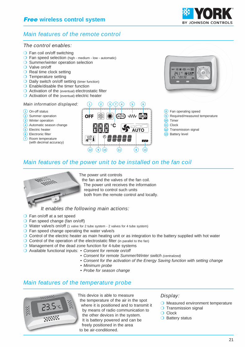
A remote control which features a button panel andLCD display and can be wall-mounted or positionedon a dedicated table support.It enables the control of all the operating variables ofthe fan coil units in different configurations. The controlis battery powered.The temperature and the operating speed of the fancoil unit are set with two large buttons featuring userfriendly graphics.
A power unit to be installed on the fan coil (fan coilinterface).It controls the fan and the valves of the fan coil. Thepower unit is connected to the electric supply.The power unit receives the information required tocontrol the fan coil both from the remote control andlocally, such as the temperature of the coil.
A room temperature probe, which can be wall-mounted or positioned on a dedicated table support.It is a battery powered device, able to measure the airtemperature in the spot where it is positioned, generatingtemperature information which is communicated to theother devices.
Main components
Free includes 3 main components:
Power unit fitted on the unit
Power unit not fitted on the unit
deScRIPtIon
Free-Upm 9060571
Free-Ups 9060570
IdentIfIcatIon code
Temperature probe
deScRIPtIon
Free-Sen 9060573
IdentIfIcatIon code
Remote control
deScRIPtIon
Free-Com 9060572
IdentIfIcatIon code
21
Free wireless control system
The power unit controlsthe fan and the valves of the fan coil.The power unit receives the informationrequired to control such unitsboth from the remote control and locally.
This device is able to measurethe temperature of the air in the spotwhere it is positioned and to transmit itby means of radio communication tothe other devices in the system.It is battery powered and can befreely positioned in the area
to be air-conditioned.
On-off statusSummer operationWinter operationAutomatic season changeElectric heaterElectronic filterRoom temperature(with decimal accuracy)
Fan operating speedRequired/measured temperatureTimerClockTransmission signalBattery level
Fan coil on/off switching Fan speed selection (high - medium - low - automatic) Summer/winter operation selection Valve on/off Real time clock setting Temperature setting Daily switch on/off setting (timer function) Enable/disable the timer function Activation of the (eventual) electrostatic filter Activation of the (eventual) electric heater
The control enables:
Main features of the remote control
Main information displayed:
Main features of the power unit to be installed on the fan coil
Main features of the temperature probe
12 10 11 138
1 2 3 7 4 5 6
9
1
2
3
4
5
6
7
8
9
10
11
12
13
Fan on/off at a set speed Fan speed change (fan on/off) Water valve/s on/off (1 valve for 2 tube system - 2 valves for 4 tube system)
Fan speed change operating the water valve/s Control of the electric heater as main heating unit or as integration to the battery supplied with hot water Control of the operation of the electrostatic filter (in parallel to the fan)
Management of the dead zone function for 4-tube systems Available functional inputs: • Consent for remote on/off • Consent for remote Summer/Winter switch (centralized)
• Consent for the activation of the Energy Saving function with setting change • Minimum probe • Probe for season change
It enables the following main actions:
Measured environment temperature Transmission signal Clock Battery status
Display:
22
Unit with infra-red remote control
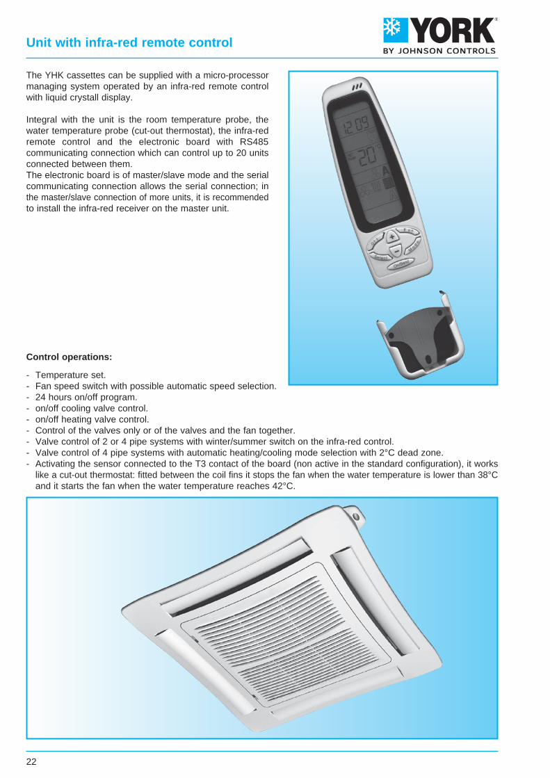
The YHK cassettes can be supplied with a micro-processormanaging system operated by an infra-red remote controlwith liquid crystall display.
Integral with the unit is the room temperature probe, thewater temperature probe (cut-out thermostat), the infra-redremote control and the electronic board with RS485communicating connection which can control up to 20 unitsconnected between them.The electronic board is of master/slave mode and the serialcommunicating connection allows the serial connection; inthe master/slave connection of more units, it is recommendedto install the infra-red receiver on the master unit.
Control operations:
- Temperature set.- Fan speed switch with possible automatic speed selection.- 24 hours on/off program.- on/off cooling valve control.- on/off heating valve control.- Control of the valves only or of the valves and the fan together.- Valve control of 2 or 4 pipe systems with winter/summer switch on the infra-red control.- Valve control of 4 pipe systems with automatic heating/cooling mode selection with 2°C dead zone.- Activating the sensor connected to the T3 contact of the board (non active in the standard configuration), it works like a cut-out thermostat: fitted between the coil fins it stops the fan when the water temperature is lower than 38°C and it starts the fan when the water temperature reaches 42°C.
The electronic board, fitted inside the electrical panel, can manage different control modes so as to best satisfy therequirements of the installation. These modes are selected by suitably positioning the configuration dipswitches,which define the following main functions:
• 2 pipe / 4 pipe system:
dip switch N.ro 1 = ON/OFF
• Operation without / with remote control:
dip switch N.ro 3 = ON/OFF
• Continuous ventilation:
dip switch N.ro 4 = ON
• Close valve and stop fan in cooling (autofan function):
dip swicth N.ro 4 = OFF N.ro 5 = ON N.ro 6 = OFF
• Close valve and stop fan in heating mode (autofan function):
dip swicth N.ro 4 = OFF N.ro 5 = OFF N.ro 6 = OFF
• Close valve and stop fan in both cooling and heating mode (autofan function):
dip swicth N.ro 4 = OFF N.ro 5 = ON N.ro 6 = ON
The autofan function allows the simultaneous on/off control of the water valve and the fan, while at the same timeoptimising the operation of the unit. When reaching the set point, the controller closes the water valve (valve off)and only 3 minutes later stops the fan, so as to correctly compensate for the valve closing time. To prevent the airprobe from measuring an incorrect temperature, when the fan is off the controller runs a number of fan ON cyclesto annul the effect of any stratification of the air in the room.
In two pipe systems, a water probe (T2 accessory) can be installed on the supply pipe to the unit upstream of thewater valve. Based on the temperature read in this section of the pipe, the device will select either cooling or heatingoperation.
The electronic board also features a contact for connection to a window switch or remote enabling signal. Whenthe contact is closed, the unit can operate, when the contact is open, the unit stops. The same contact can be usedfor starting and stopping the unit from an external timer or any other remote switching device.
In addition, a series of units can be switched on or off at the same time, by using a flip-flop switch connected tothe terminals present on the board.
Sensors that require a 12 volt power supply, for example occupancy sensors, can be connected to other terminalson the electronic board and then to the on/off contacts. The board is able to power external sensors with a maximumcurrent of 60mA.
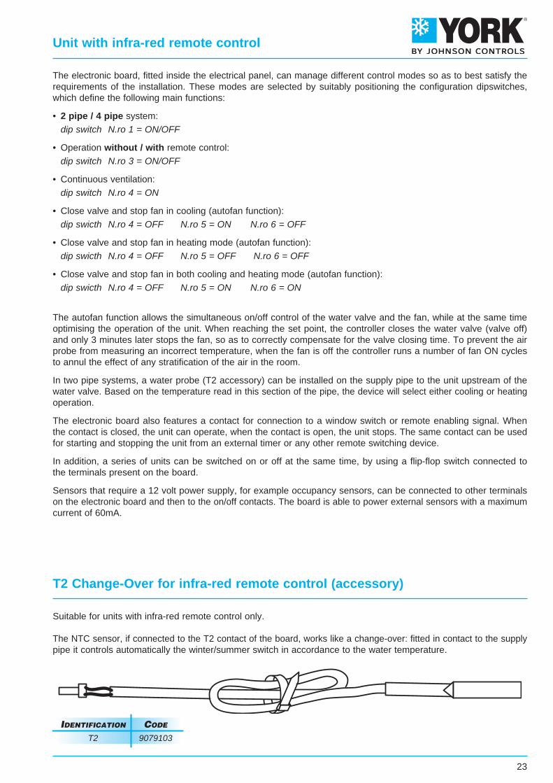
Suitable for units with infra-red remote control only.
The NTC sensor, if connected to the T2 contact of the board, works like a change-over: fitted in contact to the supplypipe it controls automatically the winter/summer switch in accordance to the water temperature.
T2 Change-Over for infra-red remote control (accessory)
23
Unit with infra-red remote control
IdentIfIcatIon code
T2 9079103
24
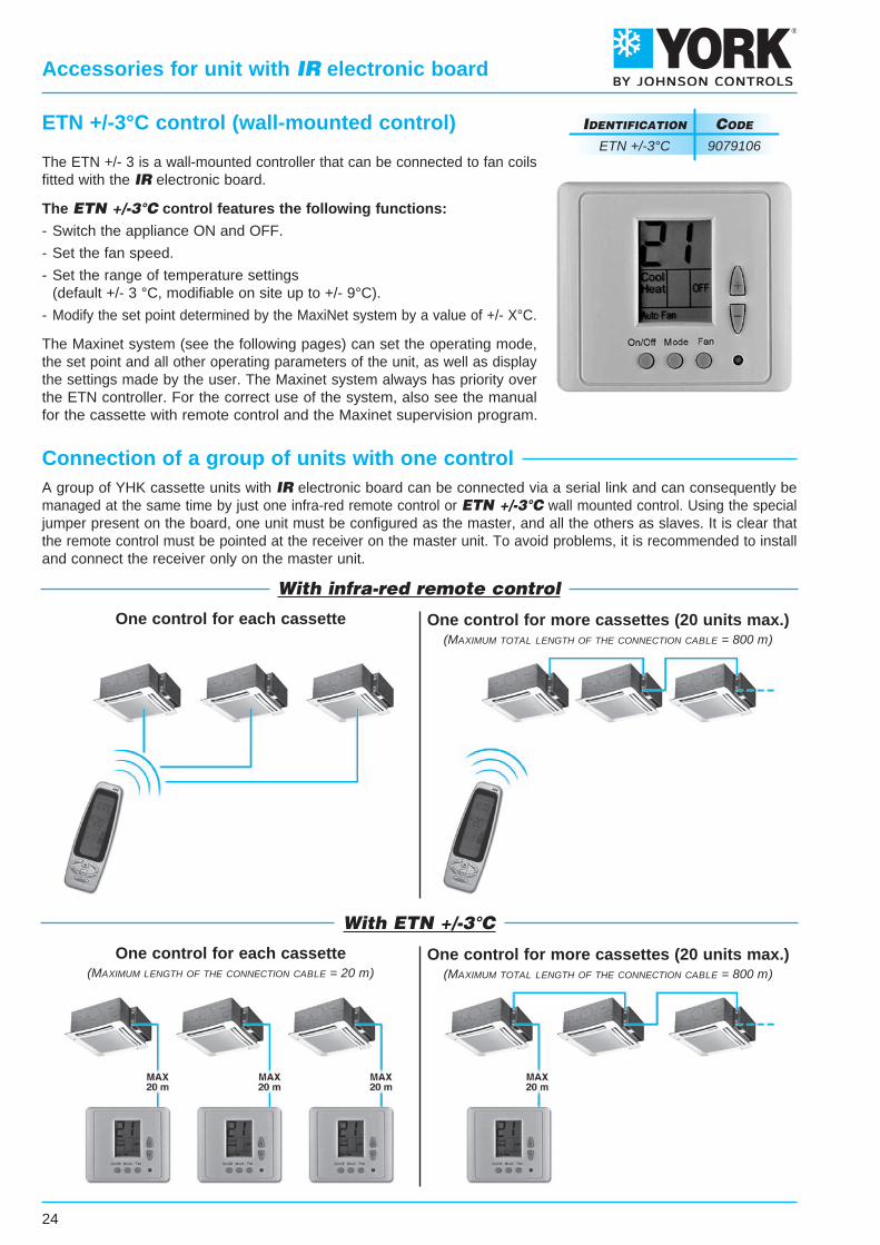
The ETN +/- 3 is a wall-mounted controller that can be connected to fan coilsfitted with the IR electronic board.
The ETN +/-3°C control features the following functions:
- Switch the appliance ON and OFF.
- Set the fan speed.
- Set the range of temperature settings (default +/- 3 °C, modifiable on site up to +/- 9°C).
- Modify the set point determined by the MaxiNet system by a value of +/- X°C.
The Maxinet system (see the following pages) can set the operating mode,the set point and all other operating parameters of the unit, as well as displaythe settings made by the user. The Maxinet system always has priority overthe ETN controller. For the correct use of the system, also see the manualfor the cassette with remote control and the Maxinet supervision program.
Accessories for unit with IR electronic board
IdentIfIcatIon code
ETN +/-3°C 9079106
ETN +/-3°C control (wall-mounted control)
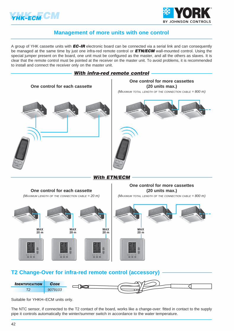
Connection of a group of units with one controlA group of YHK cassette units with IR electronic board can be connected via a serial link and can consequently bemanaged at the same time by just one infra-red remote control or ETN +/-3°C wall mounted control. Using the specialjumper present on the board, one unit must be configured as the master, and all the others as slaves. It is clear thatthe remote control must be pointed at the receiver on the master unit. To avoid problems, it is recommended to installand connect the receiver only on the master unit.
With infra-red remote control
With ETN +/-3°C
One control for each cassette One control for more cassettes (20 units max.)(MaxiMuM total length of the connection cable = 800 m)
One control for each cassette(MaxiMuM length of the connection cable = 20 m)
One control for more cassettes (20 units max.)(MaxiMuM total length of the connection cable = 800 m)
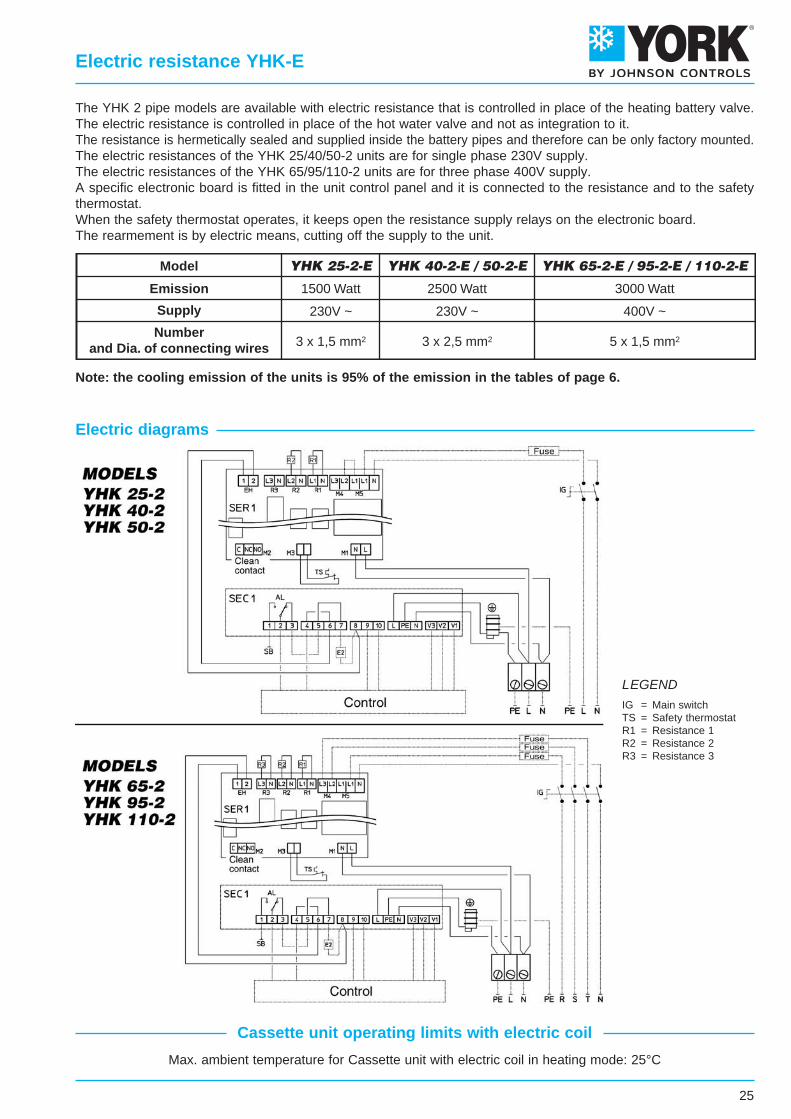
Model
Emission
Supply
Numberand Dia. of connecting wires
YHK 25-2-E YHK 65-2-E / 95-2-E / 110-2-E
1500 Watt
230V ~
3 x 1,5 mm2
YHK 40-2-E / 50-2-E
2500 Watt
230V ~
3 x 2,5 mm2
3000 Watt
400V ~
5 x 1,5 mm2
25
Max. ambient temperature for Cassette unit with electric coil in heating mode: 25°C
The YHK 2 pipe models are available with electric resistance that is controlled in place of the heating battery valve.The electric resistance is controlled in place of the hot water valve and not as integration to it.The resistance is hermetically sealed and supplied inside the battery pipes and therefore can be only factory mounted.The electric resistances of the YHK 25/40/50-2 units are for single phase 230V supply.The electric resistances of the YHK 65/95/110-2 units are for three phase 400V supply.A specific electronic board is fitted in the unit control panel and it is connected to the resistance and to the safetythermostat.When the safety thermostat operates, it keeps open the resistance supply relays on the electronic board.The rearmement is by electric means, cutting off the supply to the unit.
Note: the cooling emission of the units is 95% of the emission in the tables of page 6.
Electric diagrams
LEGENDIG = Main switchTS = Safety thermostatR1 = Resistance 1R2 = Resistance 2R3 = Resistance 3
Electric resistance YHK-E
Cassette unit operating limits with electric coil
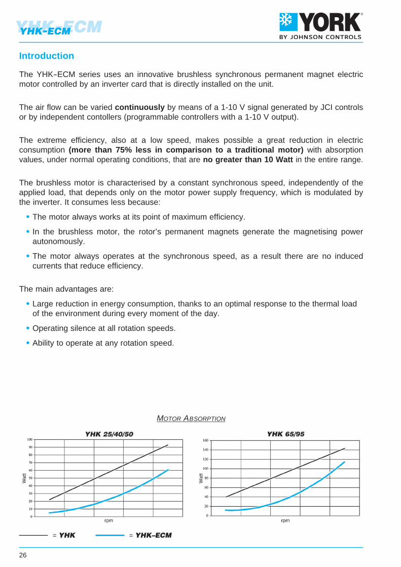
The YHK-ECM series uses an innovative brushless synchronous permanent magnet electricmotor controlled by an inverter card that is directly installed on the unit.
The air flow can be varied continuously by means of a 1-10 V signal generated by JCI controlsor by independent contollers (programmable controllers with a 1-10 V output).
The extreme efficiency, also at a low speed, makes possible a great reduction in electricconsumption (more than 75% less in comparison to a traditional motor) with absorptionvalues, under normal operating conditions, that are no greater than 10 Watt in the entire range.
The brushless motor is characterised by a constant synchronous speed, independently of theapplied load, that depends only on the motor power supply frequency, which is modulated bythe inverter. It consumes less because:
• The motor always works at its point of maximum efficiency.
• In the brushless motor, the rotor’s permanent magnets generate the magnetising power autonomously.
• The motor always operates at the synchronous speed, as a result there are no induced currents that reduce efficiency.
The main advantages are:
• Large reduction in energy consumption, thanks to an optimal response to the thermal load of the environment during every moment of the day.
• Operating silence at all rotation speeds.
• Ability to operate at any rotation speed.
Introduction
YHK-ECM
26
YHK-ECM
= YHK = YHK–ECM
Motor absorption
INTAKE GRID AND DISTRIBUTION OF THE AIRIntake grids, frame and adjustable air distribution louvers on each side, made from ABS.AKPA version : white ABS, RAL 9003AKPB version : with intake grid, frame and louvers, choice of one colour onlyAKPC version : with intake grid and louvers, choice of one colour, plus white ABS frame RAL 9003AKPD version : with louvers, choice of one colour, while the grid and frame are made from ABS, RAL 9003MD-600 version : metal diffuser painted in RAL 9003 white colour with 600x600 dimension to perfectly fit into the false ceiling standard modules without overlapping parts (800x800 model is not available).
CASINGIs made from galvanized steel with inside thermal insulation (closed cell polyethelene 10 mm thick) andoutside anti-condensate lining.
CONTROL EQUIPMENTYHKY-ECM version It consists of the pump control circuit board and the inverter circuit board.
YHKH-ECM version It consists of the IR10 electronic board (that integrates pump control) and the inverter board.
FAN ASSEMBLYThe fan assembly, which is mounted on anti-vibrating supports, is extremely silent.The radial fan has been designed to optimise performance, using wing profile blades with a shape thatreduce turbulence, increasing efficiency and reducing noise.The fans are connected to a BLAC three phase permanent magnet DC brushless electronic motor thatis controlled with current reconstructed according to a sinusoidal wave.The inverter board that controls the motor operation is powered by 230 Volt, single-phase and, with aswitching system, it generates a three-phase frequency modulated, wave form power supply.The electric power supply required for the machine is therefore single-phase with voltage of 220 - 240 Vand frequency of 50 - 60 Hz.
HEAT EXCHANGERMade of copper tubes with bonded aluminium fins for maximum transfer contact.The batteries are with 2 or 3 rows for 2 pipe models and 2+1 rows for 4 pipe models (the heating row ison the inside part of the battery).For 4 pipe systems two versions are available:YHK 25-4 and YHK 65-4 supply an higher heating emission;YHK 40-6, YHK 50-6, YHK 95-6 supply an higher cooling emission.The heat exchanger is not suitable for use in corrosive atmosphere or in environments where aluminiummay be subject to corrosion.
CONDENSATE COLLECTION TRAYHigh density ABS polystyrene foam condensate tray, shaped in order to optimize the air diffusion, fireretardant rating B2 to DIN 4102.
AIR FILTERSynthetic washable filter, easily removable.
CONDENSATE PUMPFloat switch centrifugal pump with 650 mm of maximum head, integral to the unit and wired to the controlpanel on the outside of the casing.
VALVE SETTwo or three way valves for ON/OFF operation, with pipe mounting kit and thermostatic actuator.
27
YHK-ECMYHK-ECM
Main components
1,13,6
1,43,0
0,51,7
0,51,7
0,71,4
SpeedAir flow m3/hCooling total emission kWCooling sensible emission kWWater flow l/h∆P Cooling kPaHeating kWWater flow l/h∆P Heating kPaSound power Lw dB(A)Sound pressure Lp dB(A)Fan WCooling water content lHeating water content lDimensions mm 820 x 820 x 303575 x 575 x 275
7104,983,528568,85,224496,5342510
11307,175,2
123317
7,1661611473832
17709,877,4
169730,19,51818185748108
6304,33,087409,46,1452810,5332410
8705,283,8490813,67,5464915,5393017
11656,514,83112019,89,3680522,5483933
3602,381,714094,12,21894,537287
6103,532,626088,43,062637,5504121
8804,533,4677913,13,7932611605162
1 2 31 2 31 2 3
ECM MODEL YHK 25-4 YHK 40-6 YHK 50-6 YHK 65-4 YHK 95-6
3102,091,493593,51,981703,533245
4452,812,044835,72,532175,5433411
7103,932,9567610,53,352889544531
1 2 33101,851,343184,62,432095,733245
3802,181,63756,22,852457,639308
5352,772,084769,53,6231111,7473816
1 2 3
3,0 4,01,4 2,1 2,1820 x 820 x 303575 x 575 x 275
SpeedAir flow m3/hCooling total emission kWCooling sensible emission kWHeating kWWater flow l/h∆P Cooling kPa∆P Heating kPaSound power Lw dB(A)Sound pressure Lp dB(A)Fan WWater content lDimensions mm
7105,293,695,899099,47,2342510
11307,725,538,83132818,514,9473832
177010,757,9412,73184833,628,85748108
6304,213,035,1172310,98,7332410
8705,153,776,3588515,612,8393017
11656,334,728,01108922,719,5483933
3602,561,812,964415,94,737287
6103,872,814,6366612,410,5504121
8805,023,746,286419,717,7605162
1 2 31 2 31 2 3
ECM MODEL YHK 25-2 YHK 40-2 YHK 50-2 YHK 65-2 YHK 95-2
3102,241,572,553854,63,633245
4453,052,173,585249,46,6433411
7104,333,185,2474415,113,1544531
1 2 33101,841,352,223174,9433245
3802,171,612,673736,65,539308
5352,752,093,4447310,18,7473816
1 2 3
28
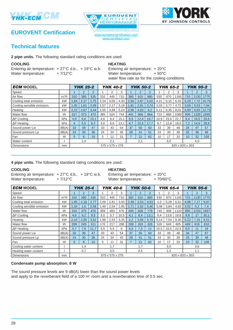
The sound pressure levels are 9 dB(A) lower than the sound power levelsand apply to the reverberant field of a 100 m3 room and a reverberation time of 0.5 sec.
2 pipe units. The following standard rating conditions are used:
COOLINGEntering air temperature: + 27°C d.b., + 19°C w.b.Water temperature: + 7/12°C
HEATINGEntering air temperature: + 20°CWater temperature: + 50°Cwater flow rate as for the cooling conditions
Technical features
4 pipe units. The following standard rating conditions are used:
COOLINGEntering air temperature: + 27°C d.b., + 19°C w.b.Water temperature: + 7/12°C
HEATINGEntering air temperature: + 20°CWater temperature: + 70/60°C
Condensate pump absorption: 8 W
YHK-ECMYHK-ECM
EUROVENT Certification www.eurovent-certification.comwww.certiflash.com
7/12 °C10/15 °C14/18 °C
KKK
0,90,720,5
0,940,780,58
1,060,9
0,72
7/12 °C10/15 °C14/18 °C
KKK
0,820,560,35
0,890,630,41
1,110,820,52
Water (°C) Air (°C) 25-18 26-18.5 28-20 Water (°C) Air (°C) 25-18 26-18.5 28-20Total emission Sensible emission Note:
the correctionfactors are indicative,as they areaverage values.
Emission correction factors for different working conditions.Multiply the factors by the emission figures in the 7-12°C table above.
YHK25-2
YHK40-2
YHK50-2
YHK65-2
YHK95-2
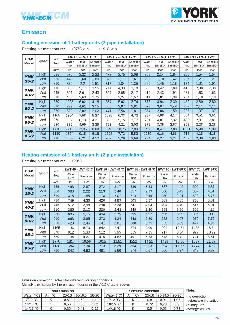
493383318749512365886663423
1152912734
18171262842
2,872,221,854,362,982,125,153,852,466,705,304,27
10,567,344,90
272213178420290209494373241642512415
1015713481
3,172,482,074,893,382,435,754,342,817,475,954,82
11,818,295,60
330257214505347249595448288774615497
1222854574
3,832,992,495,874,042,906,925,203,359,007,155,78
14,219,936,67
387300250589404289696522335904717578
1428994666
4,493,492,916,854,703,368,096,073,89
10,518,346,72
16,6011,567,74
500387322758517368896670427
1165922741
18371274849
5,824,513,758,816,014,28
10,427,794,96
13,5410,728,61
21,3714,829,87
535380310710445310880610360
1165870630
17701130710
SpeedAirflow
ECMModel
HighMedLowHighMedLowHighMedLowHighMedLow
HighMedLow
EWT 45 - LWT 40°C EWT 50 - LWT 40°C EWT 55 - LWT 45°C EWT 60 - LWT 50°C EWT 70 - LWT 60°C
l/hm3/h kW l/h kW l/h kW l/h kW l/h kW
Waterflow Emission
Waterflow Emission
Waterflow Emission
Waterflow Emission
Waterflow Emission
YHK25-2
YHK40-2
YHK50-2
YHK65-2
YHK95-2
570448379888621453
1035793520
13041055859
221015741068
3,322,602,2
5,173,612,636,024,613,027,586,134,99
12,859,156,21
2,331,801,513,552,431,754,183,152,025,274,213,398,886,184,12
473373317744524385864666441
1089885723
18481328909
2,752,171,844,333,052,245,023,872,566,335,154,21
10,757,725,29
2,091,611,353,182,171,573,742,811,814,723,773,037,945,533,69
368293250588419311678528354857701576
14561059734
2,141,701,453,422,431,813,943,072,064,984,073,358,476,164,27
1,841,421,182,801,911,383,302,481,594,173,322,677,004,863,24
266207174410281204482363235604483392
1031718482
1,541,211,012,381,631,182,802,111,373,512,812,285,994,182,80
1,541,211,012,381,631,182,802,111,373,512,812,285,994,182,80
535380310710445310880610360
1165870630
17701130710
SpeedAirflow
ECMModel
HighMedLowHighMedLowHighMedLowHighMedLow
HighMedLow
EWT 5 - LWT 10°C EWT 7 - LWT 12°C EWT 9 - LWT 14°C EWT 12 - LWT 17°CWaterflow
Totalemission
Sensibleemission
Waterflow
Totalemission
Sensibleemission
Waterflow
Totalemission
Sensibleemission
Waterflow
Totalemission
Sensibleemission
l/h kW kW l/h kW kW l/h kW kW l/h kW kWm3/h
29
YHK-ECMYHK-ECM
Emission
Cooling emission of 1 battery units (2 pipe installation)Entering air temperature: +27°C d.b. +19°C w.b.
Heating emission of 1 battery units (2 pipe installation)Entering air temperature: +20°C
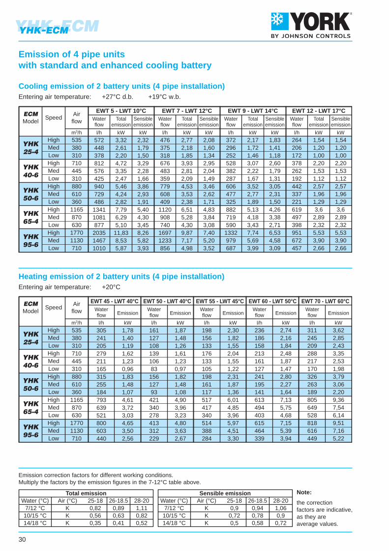
7/12 °C10/15 °C14/18 °C
KKK
0,90,720,5
0,940,780,58
1,060,9
0,72
7/12 °C10/15 °C14/18 °C
KKK
0,820,560,35
0,890,630,41
1,110,820,52
Water (°C) Air (°C) 25-18 26-18.5 28-20 Water (°C) Air (°C) 25-18 26-18.5 28-20Total emission Sensible emission Note:
the correctionfactors are indicative,as they areaverage values.
Emission of 4 pipe unitswith standard and enhanced cooling battery
Emission correction factors for different working conditions.Multiply the factors by the emission figures in the 7-12°C table above.
YHK25-4
YHK40-6
YHK50-6
YHK65-4
YHK95-6
572448378812576425940729486
13411081877
203514671010
3,322,612,204,723,352,475,464,242,827,796,295,10
11,838,535,87
2,321,791,503,292,281,663,862,931,915,404,303,458,265,823,93
476375318676483359779608409
1120908740
16971233856
2,772,181,853,932,812,094,533,532,386,515,284,309,877,174,98
2,081,601,342,952,041,493,462,621,714,833,843,087,405,203,52
372296252528382287606477325882719590
1332979687
2,171,721,463,072,221,673,522,771,895,134,183,437,745,693,99
1,831,411,182,601,791,313,052,311,504,263,382,716,534,583,09
264206172378262192442337221619497398951672457
1,541,201,002,201,531,122,571,961,293,6
2,892,325,533,902,66
1,541,201,002,201,531,122,571,961,293,6
2,892,325,533,902,66
535380310710445310880610360
1165870630
17701130710
SpeedAirflow
ECMModel
HighMedLowHighMedLowHighMedLowHighMedLow
HighMedLow
EWT 5 - LWT 10°C EWT 7 - LWT 12°C EWT 9 - LWT 14°C EWT 12 - LWT 17°CWaterflow
Totalemission
Sensibleemission
Waterflow
Totalemission
Sensibleemission
Waterflow
Totalemission
Sensibleemission
Waterflow
Totalemission
Sensibleemission
l/h kW kW l/h kW kW l/h kW kW l/h kW kWm3/h
YHK25-4
YHK40-6
YHK50-6
YHK65-4
YHK95-6
305241205279211165315255184793639521800603440
1,781,401,191,621,230,961,831,481,074,613,723,034,653,502,56
16112710813910683
15612793
421340278413312229
1,871,481,261,611,230,971,821,481,084,903,963,234,803,632,67
198156133176133105198161117517417340514388284
2,301,821,552,041,551,222,311,871,366,014,853,965,974,513,30
236186158213161127241195141613494403615464339
2,742,161,842,481,871,472,802,271,647,135,754,687,155,393,94
311245209288217170326263189805649528818616449
3,622,852,433,352,531,983,793,062,209,367,546,149,517,165,22
535380310710445310880610360
1165870630
17701130710
SpeedAirflow
ECMModel
HighMedLowHighMedLowHighMedLowHighMedLow
HighMedLow
EWT 45 - LWT 40°C EWT 50 - LWT 40°C EWT 55 - LWT 45°C EWT 60 - LWT 50°C EWT 70 - LWT 60°C
l/hm3/h kW l/h kW l/h kW l/h kW l/h kW
Waterflow Emission
Waterflow Emission
Waterflow Emission
Waterflow Emission
Waterflow Emission
YHK-ECM
30
YHK-ECM
Cooling emission of 2 battery units (4 pipe installation)Entering air temperature: +27°C d.b. +19°C w.b.
Heating emission of 2 battery units (4 pipe installation)Entering air temperature: +20°C
Water flow
Air flow
Supply
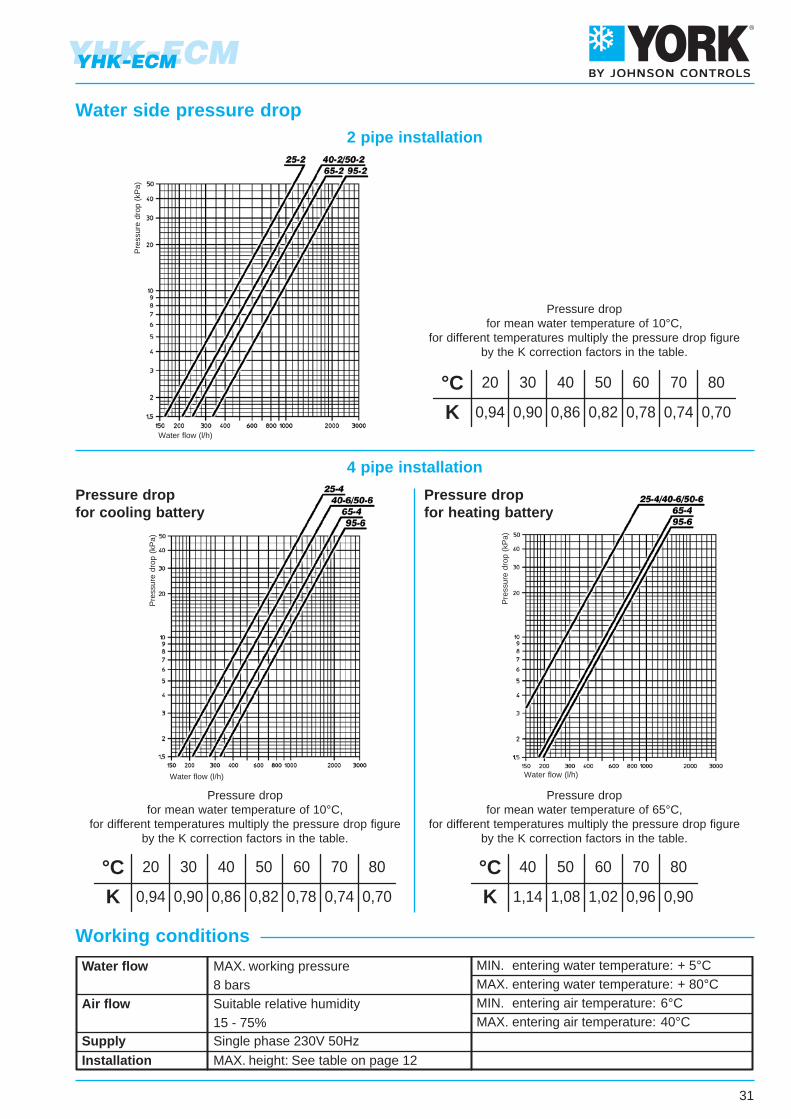
MAX. working pressure8 barsSuitable relative humidity15 - 75%Single phase 230V 50Hz
MIN. entering water temperature: + 5°CMAX. entering water temperature: + 80°CMIN. entering air temperature: 6°CMAX. entering air temperature: 40°C
Installation MAX. height: See table on page 12
°CK
40
1,14
50
1,08
60
1,02
70
0,96
80
0,90
°CK
20
0,94
30
0,90
40
0,86
50
0,82
60
0,78
70
0,74
80
0,70
°CK
20
0,94
30
0,90
40
0,86
50
0,82
60
0,78
70
0,74
80
0,70
Pressure dropfor mean water temperature of 10°C,
for different temperatures multiply the pressure drop figureby the K correction factors in the table.
Pressure dropfor mean water temperature of 65°C,
for different temperatures multiply the pressure drop figureby the K correction factors in the table.
Working conditions
Pressure dropfor mean water temperature of 10°C,
for different temperatures multiply the pressure drop figureby the K correction factors in the table.
Pressure dropfor cooling battery
Pressure dropfor heating battery
2 pipe installation
4 pipe installation
31
YHK-ECMYHK-ECM
Water side pressure dropP
ress
ure
drop
(kP
a)
Water flow (l/h)
Pre
ssur
e dr
op (
kPa)
Water flow (l/h)
Pre
ssur
e dr
op (
kPa)
Water flow (l/h)
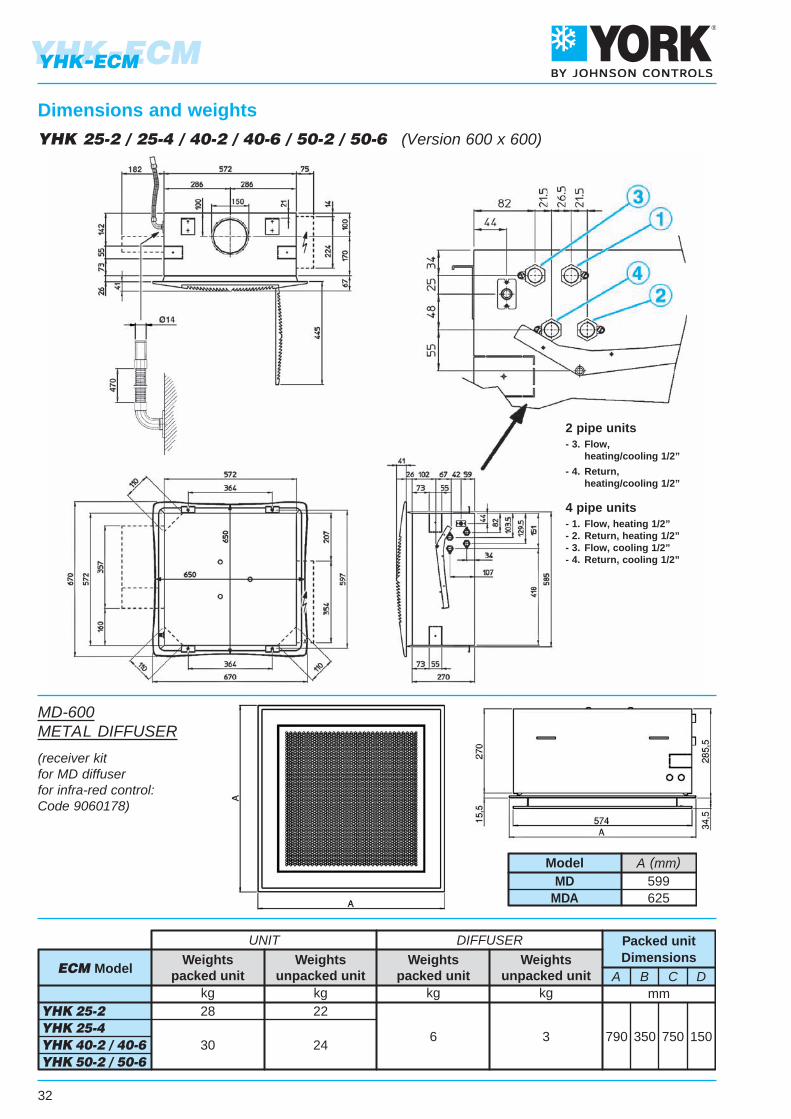
790 350 750 150
A B C Dmm
30 246 3
kg kg
Weightspacked unit
Weightsunpacked unit
YHK 25-2 YHK 25-4 YHK 40-2 / 40-6 YHK 50-2 / 50-6
28 22
UNIT DIFFUSER
kg kg
ECM ModelWeights
packed unitWeights
unpacked unit
Packed unitDimensions
2 pipe units- 3. Flow, heating/cooling 1/2”
- 4. Return, heating/cooling 1/2”
4 pipe units- 1. Flow, heating 1/2”- 2. Return, heating 1/2”- 3. Flow, cooling 1/2”- 4. Return, cooling 1/2”
YHK 25-2 / 25-4 / 40-2 / 40-6 / 50-2 / 50-6 (Version 600 x 600)
YHK-ECM
32
YHK-ECM
Dimensions and weights
MD-600METAL DIFFUSER
(receiver kitfor MD diffuserfor infra-red control:Code 9060178)
A (mm)MD
MDA599625
Model
1050 400 1000 20010 6
Packed unitDimensions
A B C Dmm
47 39
kg kg
Weightspacked unit
Weightsunpacked unit
YHK 65-2 YHK 65-4 YHK 95-2 / 95-4
44 36
UNIT DIFFUSER
kg kg
ECM ModelWeights
packed unitWeights
unpacked unit
2 pipe units- 3. Flow, heating/cooling 3/4”
- 4. Return, heating/cooling 3/4”
4 pipe units- 1. Flow, heating 1/2”- 2. Return, heating 1/2”- 3. Flow, cooling 3/4”- 4. Return, cooling 3/4”
PACKED UNIT
YHK 65-2 / 65-4 / 95-2 / 95-6 (Version 800 x 800)
33
YHK-ECMYHK-ECM
Dimensions and weights
UNIT DIFFUSER
With adjustableair diffusion louvers at 30°
With adjustableair diffusion louvers at 45°
YHK 25 YHK 40 YHK 50 YHK 65 YHK 951 2 3
3,32,22,5
3,92,62,9
4,22,83,1
1 2 33,32,22,5
4,22,83,1
4,83,23,6
1 2 33,92,62,9
4,53,03,4
5,23,43,9
1 2 33,52,22,7
4,12,63,2
4,83,03,8
1 2 33,82,43,0
4,62,83,6
5,43,44,2
SpeedAir throw L mHeight H mDistance B m
ECM Model
YHK 25 YHK 40 YHK 50 YHK 65 YHK 951 2 3
3,0 3,5 3,81 2 3
3,0 3,8 4,51 2 3
3,5 4,2 5,01 2 3
3,2 3,7 4,31 2 3
3,4 4,0 5,0SpeedAir throw L m
ECM Model
NOTE: On heating it must be payed attention to rooms where the floor temperature is particularly low (for example less than 5°C). In this situation the floor can cool the lower layer of air to a level that stop the uniform diffusion of the hot air coming from the unit, decreasing the throw figures shown in the table.
The air throw indicated in the tables must only be considered the maximum value, as it maychange significantly in relation to the dimensions of the room in which the appliance is installedand the positioning of the furniture in the room.
The useful throw L refers to the distance between the unit and the point where the air speedis 0.2 m/sec; if the louver has a gradient of 30° (recommended in cooling mode), the so-called“Coanda” effect will occur, illustrated in the first figure, while at a gradient of 45° (recommendedin heating mode), there will be a downwards throw, as illustrated in the second figure.
YHK-ECM
34
YHK-ECM
Air throw
35
YHK-ECMYHK-ECM
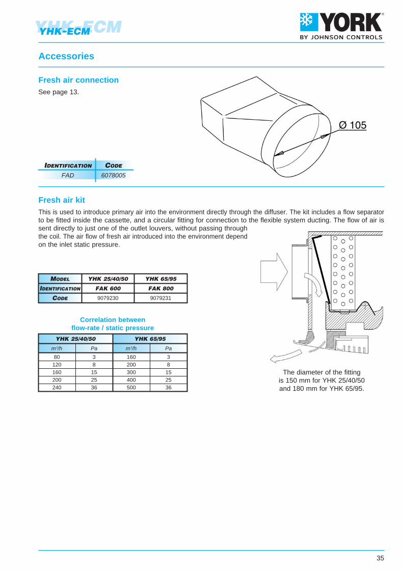
Fresh air connectionSee page 13.
IdentIfIcatIon code
FAD 6078005
Fresh air kitThis is used to introduce primary air into the environment directly through the diffuser. The kit includes a flow separatorto be fitted inside the cassette, and a circular fitting for connection to the flexible system ducting. The flow of air issent directly to just one of the outlet louvers, without passing throughthe coil. The air flow of fresh air introduced into the environment dependon the inlet static pressure.
The diameter of the fittingis 150 mm for YHK 25/40/50and 180 mm for YHK 65/95.
faK 800
YHK 65/95
9079231
faK 600
YHK 25/40/50
9079230
IdentIfIcatIon
Model
code
Correlation betweenflow-rate / static pressure
YHK 25/40/50 YHK 65/95
160200300400500
80120160200240
m3/hm3/h
38
152536
38
152536
PaPa
Accessories
36
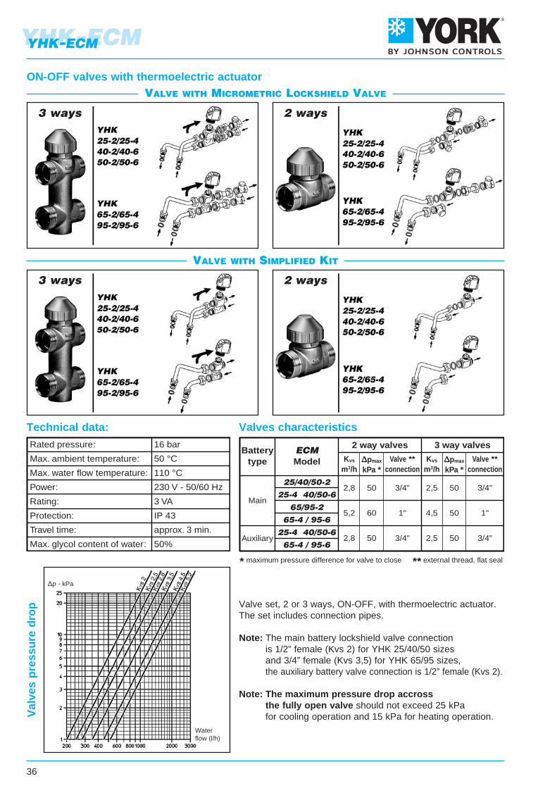
Valve set, 2 or 3 ways, ON-OFF, with thermoelectric actuator.The set includes connection pipes.
Note: The main battery lockshield valve connection is 1/2” female (Kvs 2) for YHK 25/40/50 sizes and 3/4” female (Kvs 3,5) for YHK 65/95 sizes, the auxiliary battery valve connection is 1/2” female (Kvs 2).
Note: The maximum pressure drop accross the fully open valve should not exceed 25 kPa for cooling operation and 15 kPa for heating operation.V
alve
s p
ress
ure
dro
p
ON-OFF valves with thermoelectric actuator
3 ways 2 ways
3 ways 2 ways
Batterytype
Main
ECMModel
Auxiliary
25/40/50-2
25-4 40/50-6
65/95-2
65-4 / 95-6
25-4 40/50-6
65-4 / 95-6
2 way valves 3 way valves
Kvs
m3/h∆pmax
kPa *Valve **
connectionKvs
m3/h∆pmax
kPa *Valve **
connection
2,8
5,2
2,8
50
60
50
3/4"
1"
3/4"
2,5
4,5
2,5
50
50
50
3/4"
1"
3/4"
* maximum pressure difference for valve to close ** external thread, flat seal
Rated pressure:
Max. ambient temperature:
Max. water flow temperature:
Power:
Rating:
Protection:
Travel time:
Max. glycol content of water:
16 bar
50 °C
110 °C
230 V - 50/60 Hz
3 VA
IP 43
approx. 3 min.
50%
Technical data: Valves characteristics
ValVe with MicroMetric lockshield ValVe
ValVe with siMplified kit
YHK-ECMYHK-ECM
Waterflow (l/h)
∆p - kPa
37
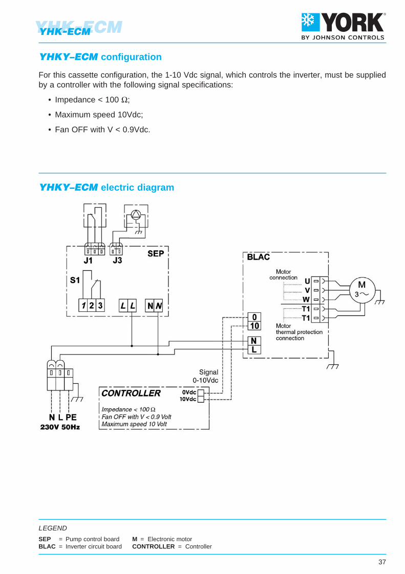
LEGEND
SEP = Pump control boardBLAC = Inverter circuit board
M = Electronic motorCONTROLLER = Controller
For this cassette configuration, the 1-10 Vdc signal, which controls the inverter, must be suppliedby a controller with the following signal specifications:
• Impedance < 100 Ω;
• Maximum speed 10Vdc;
• Fan OFF with V < 0.9Vdc.
YHKY–ECM configuration
YHKY–ECM electric diagram
YHK-ECMYHK-ECM
38
YHK-ECMYHK-ECM
Power unit to be installedon the fan coil (fan coil interface).It controls the fan and the valves of the fan coil.The power unitis connected to the electric supply.The power unit receives
the information required from the control.
Power unit for CR-T-ECM remote control (fitted on the unit)
Power unit for CR-T-ECM remote control (not fitted on the unit)
deScRIPtIon
UPM-ECM 9066341
UPS-ECM 9066340
IdentIfIcatIon code
Dimensions: 133x93x37 mm
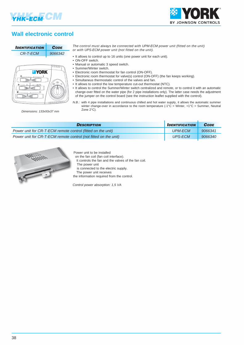
Wall electronic control
The control must always be connected with UPM-ECM power unit (fitted on the unit)or with UPS-ECM power unit (not fitted on the unit).
• It allows to control up to 16 units (one power unit for each unit).• ON-OFF switch.• Manual or automatic 3 speed switch.• Summer/Winter switch.• Electronic room thermostat for fan control (ON-OFF).• Electronic room thermostat for valve(s) control (ON-OFF) (the fan keeps working).• Simultaneus thermostatic control of the valves and fan.• It allows to control the low temperature cut-out thermostat (NTC).• It allows to control the Summer/Winter switch centralized and remote, or to control it with an automatic change-over fitted on the water pipe (for 2 pipe installations only). The latter case needs the adjustment of the jumper on the control board (see the instruction leaflet supplied with the control).
N.B.: with 4 pipe installations and continuous chilled and hot water supply, it allows the automatic summer winter change-over in accordance to the room temperature (-1°C = Winter, +1°C = Summer, Neutral Zone 2°C).
IdentIfIcatIon code
CR-T-ECM 9066342
Control power absorption: 1,5 VA
RED
BLACK
39
YHK-ECMYHK-ECM
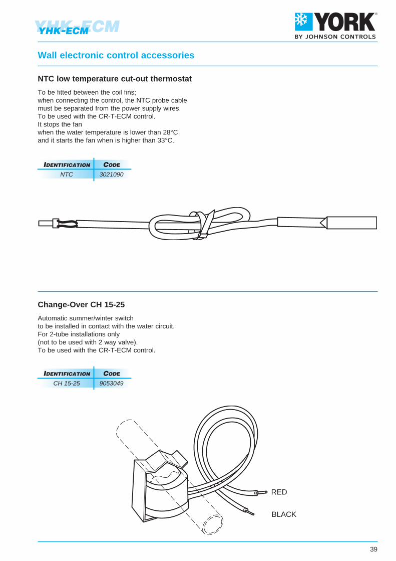
To be fitted between the coil fins;when connecting the control, the NTC probe cablemust be separated from the power supply wires.To be used with the CR-T-ECM control.It stops the fanwhen the water temperature is lower than 28°Cand it starts the fan when is higher than 33°C.
NTC low temperature cut-out thermostat
Wall electronic control accessories
Automatic summer/winter switchto be installed in contact with the water circuit.For 2-tube installations only(not to be used with 2 way valve).To be used with the CR-T-ECM control.
Change-Over CH 15-25
IdentIfIcatIon code
NTC 3021090
IdentIfIcatIon code
CH 15-25 9053049
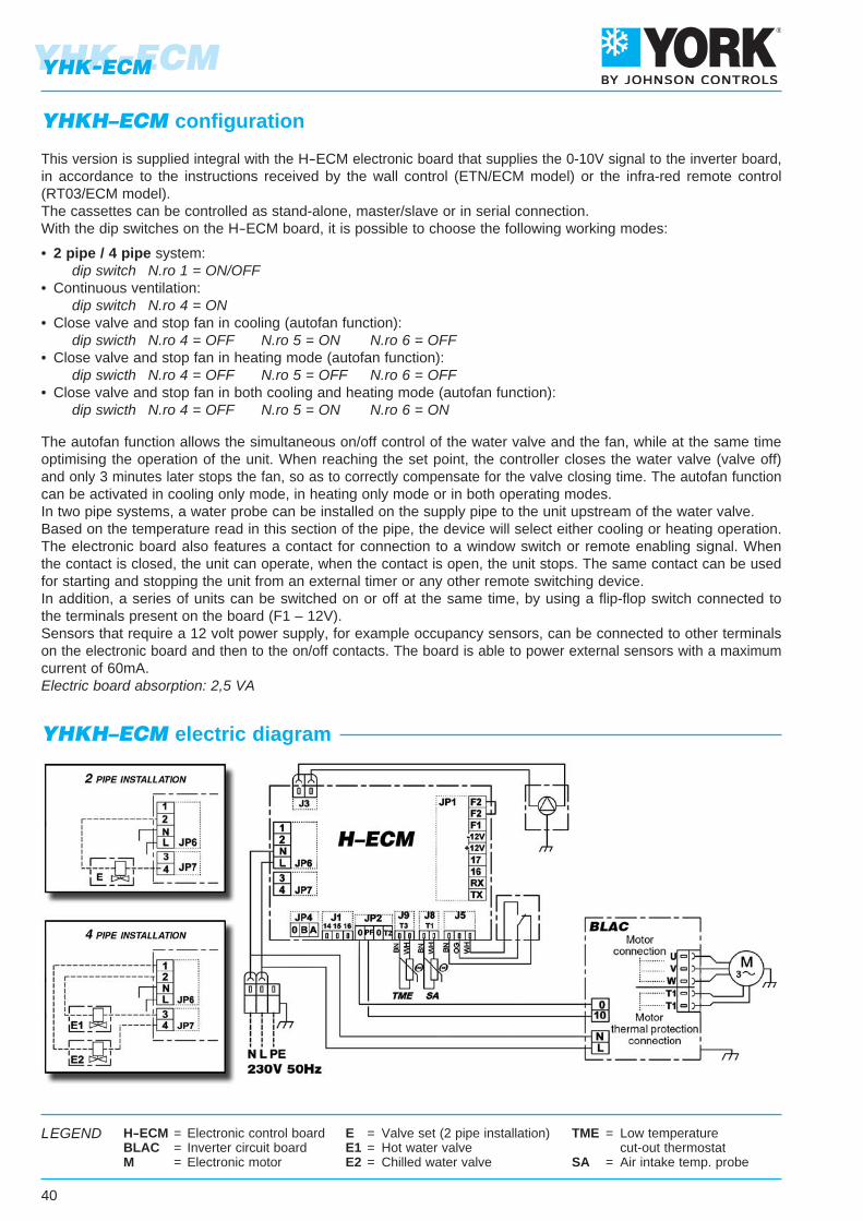
H-ECM = Electronic control boardBLAC = Inverter circuit boardM = Electronic motor
E = Valve set (2 pipe installation)E1 = Hot water valveE2 = Chilled water valve
TME = Low temperature cut-out thermostatSA = Air intake temp. probe
LEGEND
YHK-ECM
40
YHK-ECM
YHKH–ECM configuration
YHKH–ECM electric diagram
This version is supplied integral with the H-ECM electronic board that supplies the 0-10V signal to the inverter board,in accordance to the instructions received by the wall control (ETN/ECM model) or the infra-red remote control(RT03/ECM model).The cassettes can be controlled as stand-alone, master/slave or in serial connection.With the dip switches on the H-ECM board, it is possible to choose the following working modes:
• 2 pipe / 4 pipe system: dip switch N.ro 1 = ON/OFF• Continuous ventilation: dip switch N.ro 4 = ON• Close valve and stop fan in cooling (autofan function): dip swicth N.ro 4 = OFF N.ro 5 = ON N.ro 6 = OFF• Close valve and stop fan in heating mode (autofan function): dip swicth N.ro 4 = OFF N.ro 5 = OFF N.ro 6 = OFF• Close valve and stop fan in both cooling and heating mode (autofan function): dip swicth N.ro 4 = OFF N.ro 5 = ON N.ro 6 = ON
The autofan function allows the simultaneous on/off control of the water valve and the fan, while at the same timeoptimising the operation of the unit. When reaching the set point, the controller closes the water valve (valve off)and only 3 minutes later stops the fan, so as to correctly compensate for the valve closing time. The autofan functioncan be activated in cooling only mode, in heating only mode or in both operating modes.In two pipe systems, a water probe can be installed on the supply pipe to the unit upstream of the water valve.Based on the temperature read in this section of the pipe, the device will select either cooling or heating operation.The electronic board also features a contact for connection to a window switch or remote enabling signal. Whenthe contact is closed, the unit can operate, when the contact is open, the unit stops. The same contact can be usedfor starting and stopping the unit from an external timer or any other remote switching device.In addition, a series of units can be switched on or off at the same time, by using a flip-flop switch connected tothe terminals present on the board (F1 – 12V).Sensors that require a 12 volt power supply, for example occupancy sensors, can be connected to other terminalson the electronic board and then to the on/off contacts. The board is able to power external sensors with a maximumcurrent of 60mA.Electric board absorption: 2,5 VA

41
YHK-ECMYHK-ECM
The ETN/ECM control features the following functions:
- Switch the appliance ON and OFF.
- Set the fan speed.
- Set the range of temperature settings (default +/- 3 °C, modifiable on site up to +/- 9°C).
- Modify the set point determined by the MaxiNet system by a value of +/- X°C.
The Maxinet system (see the following pages) can set the operating mode,the set point and all other operating parameters of the unit, as well as displaythe settings made by the user. The Maxinet system always has priority overthe ETN controller. For the correct use of the system, also see the manualfor the cassette with remote control and the Maxinet supervision program.
ETN/ECM control (wall-mounted control) IdentIfIcatIon code
ETN/ECM 3021232
The infra-red remote controlfeatures the following functions:
- Temperature set.
- Fan speed switch with possible automatic speed selection.
- 24 hours ON/OFF program.
- ON/OFF cooling valve control.
- ON/OFF heating valve control.
- Control of the valves only or of the valves and the fan together.
- Valve control of 2 or 4 pipe systems with winter/summer switch on the infra-red control.
- Valve control of 4 pipe systems with automatic heating/cooling mode selection with 2°C dead zone.
Infra-red remote control with receiver IdentIfIcatIon code
RT03/ECM 9079220
installation exaMple
with infra-red reMote control
YHK-ECM
42
YHK-ECM
Management of more units with one control
With ETN/ECM
One control for each cassette
Suitable for YHKH–ECM units only.
The NTC sensor, if connected to the T2 contact of the board, works like a change-over: fitted in contact to the supplypipe it controls automatically the winter/summer switch in accordance to the water temperature.
IdentIfIcatIon code
T2 9079103
One control for more cassettes(20 units max.)
(MaxiMuM total length of the connection cable = 800 m)
One control for each cassette(MaxiMuM length of the connection cable = 20 m)
One control for more cassettes(20 units max.)
(MaxiMuM total length of the connection cable = 800 m)
A group of YHK cassette units with EC–IR electronic board can be connected via a serial link and can consequentlybe managed at the same time by just one infra-red remote control or ETN/ECM wall-mounted control. Using thespecial jumper present on the board, one unit must be configured as the master, and all the others as slaves. It isclear that the remote control must be pointed at the receiver on the master unit. To avoid problems, it is recommendedto install and connect the receiver only on the master unit.
T2 Change-Over for infra-red remote control (accessory)
With infra-red remote control
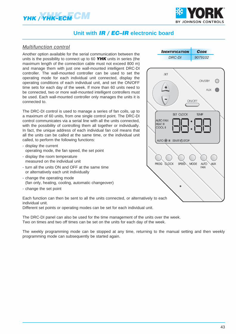
43
Unit with IR / EC–IR electronic board
Multifunction controlAnother option available for the serial communication between theunits is the possibility to connect up to 60 YHK units in series (themaximum length of the connection cable must not exceed 800 m)and manage them with just one wall-mounted intelligent DRC-DIcontroller. The wall-mounted controller can be used to set theoperating mode for each individual unit connected, display theoperating conditions of each individual unit, and set the ON/OFFtime sets for each day of the week. If more than 60 units need tobe connected, two or more wall-mounted intelligent controllers mustbe used. Each wall-mounted controller only manages the units it isconnected to.
The DRC-DI control is used to manage a series of fan coils, up toa maximum of 60 units, from one single control point. The DRC-DIcontrol communicates via a serial line with all the units connected,with the possibility of controlling them all together or individually.In fact, the unique address of each individual fan coil means thatall the units can be called at the same time, or the individual unitcalled, to perform the following functions:
- display the current operating mode, the fan speed, the set point
- display the room temperature measured on the individual unit
- turn all the units ON and OFF at the same time or alternatively each unit individually
- change the operating mode (fan only, heating, cooling, automatic changeover)
- change the set point
Each function can then be sent to all the units connected, or alternatively to eachindividual unit.Different set points or operating modes can be set for each individual unit.
The DRC-DI panel can also be used for the time management of the units over the week.Two on times and two off times can be set on the units for each day of the week.
The weekly programming mode can be stopped at any time, returning to the manual setting and then weeklyprogramming mode can subsequently be started again.
IdentIfIcatIon code
DRC-DI 9079102
YHK-ECMYHK / YHK-ECM
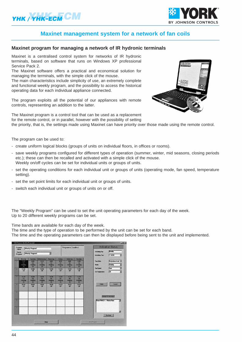
44
YHK-ECMYHK / YHK-ECM
Maxinet management system for a network of fan coils
Maxinet is a centralised control system for networks of IR hydronicterminals, based on software that runs on Windows XP professionalService Pack 2.The Maxinet software offers a practical and economical solution formanaging the terminals, with the simple click of the mouse.The main characteristics include simplicity of use, an extremely completeand functional weekly program, and the possibility to access the historicaloperating data for each individual appliance connected.
The program exploits all the potential of our appliances with remotecontrols, representing an addition to the latter.
The Maxinet program is a control tool that can be used as a replacementfor the remote control, or in parallel, however with the possibility of settingthe priority, that is, the settings made using Maxinet can have priority over those made using the remote control.
The program can be used to:
- create uniform logical blocks (groups of units on individual floors, in offices or rooms).
- save weekly programs configured for different types of operation (summer, winter, mid seasons, closing periods etc.); these can then be recalled and activated with a simple click of the mouse. Weekly on/off cycles can be set for individual units or groups of units.
- set the operating conditions for each individual unit or groups of units (operating mode, fan speed, temperature setting).
- set the set point limits for each individual unit or groups of units.
- switch each individual unit or groups of units on or off.
The “Weekly Program” can be used to set the unit operating parameters for each day of the week.Up to 20 different weekly programs can be set.
Time bands are available for each day of the week.The time and the type of operation to be performed by the unit can be set for each band.The time and the operating parameters can then be displayed before being sent to the unit and implemented.
Maxinet program for managing a network of IR hydronic terminals
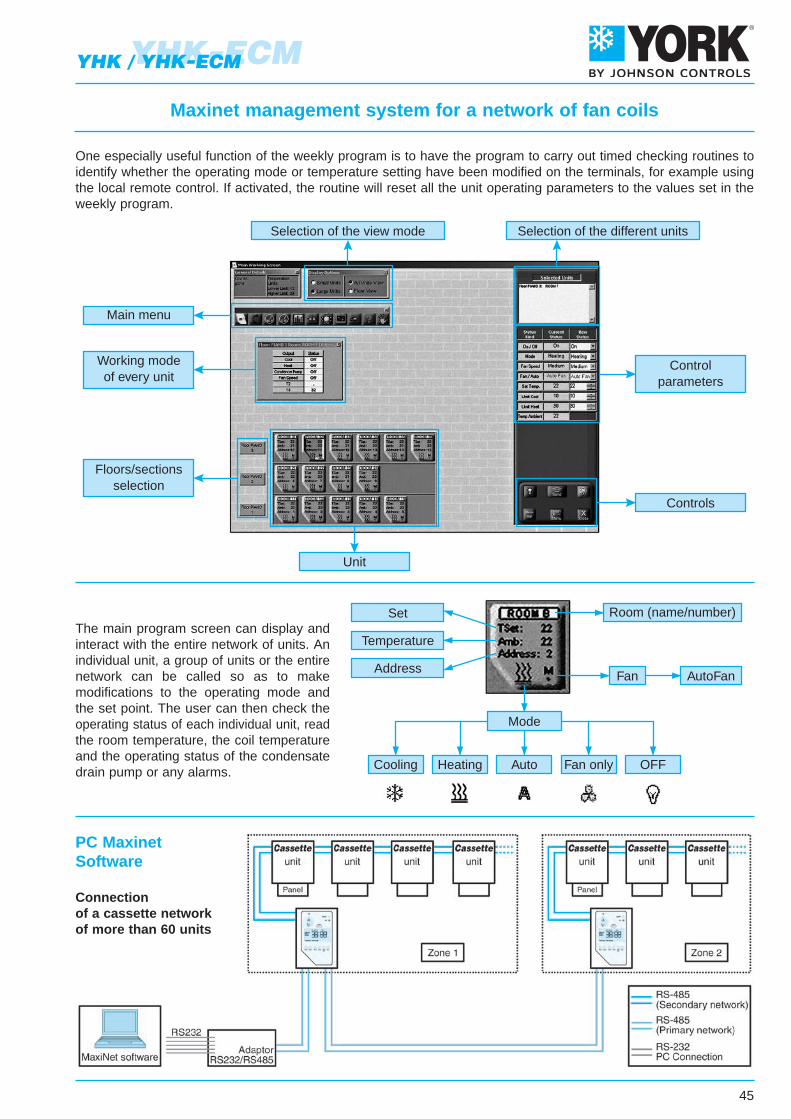
45
YHK-ECMYHK / YHK-ECM
Auto Fan only OFFHeatingCooling
Temperature
Set
AddressFan AutoFan
Mode
Room (name/number)
Selection of the different unitsSelection of the view mode
Floors/sectionsselection
Controlparameters
Controls
Unit
Main menu
Working modeof every unit
The main program screen can display andinteract with the entire network of units. Anindividual unit, a group of units or the entirenetwork can be called so as to makemodifications to the operating mode andthe set point. The user can then check theoperating status of each individual unit, readthe room temperature, the coil temperatureand the operating status of the condensatedrain pump or any alarms.
Maxinet management system for a network of fan coils
One especially useful function of the weekly program is to have the program to carry out timed checking routines toidentify whether the operating mode or temperature setting have been modified on the terminals, for example usingthe local remote control. If activated, the routine will reset all the unit operating parameters to the values set in theweekly program.
PC MaxinetSoftware
Connectionof a cassette networkof more than 60 units

46
YHK-ECMYHK / YHK-ECM
Accessories MaxiNet 7
In addition to the air-conditioning units, MaxiNet can also work withgeneral output cards.Each card contains 8 outputs which can be connected to “On / Off”devices.Inserting a new output card can be done through the regular unitssetting.Handling the existing output cards is done through the output cards’menu, which can be loaded from the working screen’s menu bar.In the menu, choose the “General Outputs Cards” title.The Out-Put card can be connected in a Maxinet network and controlled by the software. Up to 10 cards can used.
IdentIfIcatIon code
S08R 9079105
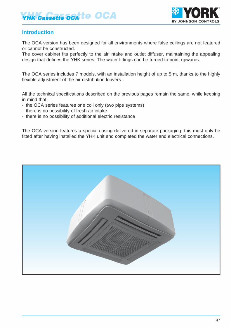
Introduction
The OCA version has been designed for all environments where false ceilings are not featuredor cannot be constructed.The cover cabinet fits perfectly to the air intake and outlet diffuser, maintaining the appealingdesign that defines the YHK series. The water fittings can be turned to point upwards.
The OCA series includes 7 models, with an installation height of up to 5 m, thanks to the highlyflexible adjustment of the air distribution louvers.
All the technical specifications described on the previous pages remain the same, while keepingin mind that:- the OCA series features one coil only (two pipe systems)- there is no possibility of fresh air intake- there is no possibility of additional electric resistance
The OCA version features a special casing delivered in separate packaging; this must only befitted after having installed the YHK unit and completed the water and electrical connections.
47
YHK Cassette OCAYHK Cassette OCA
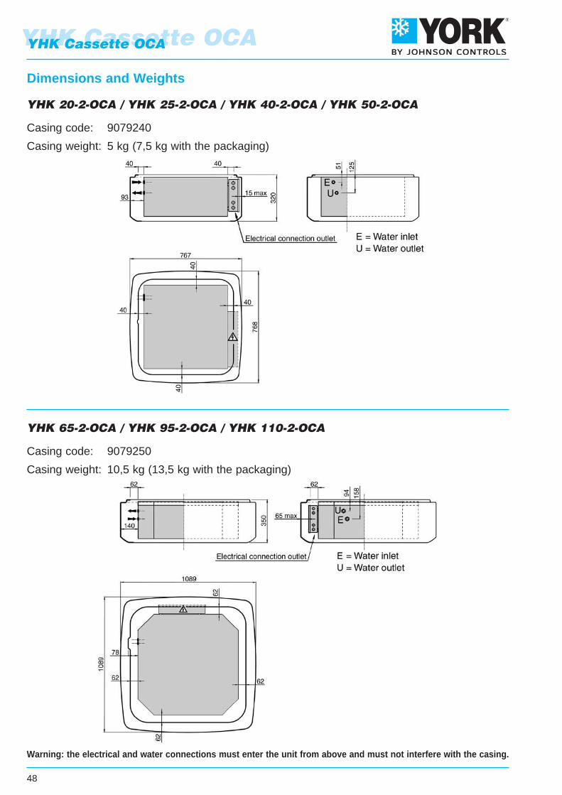
YHK Cassette OCA
Dimensions and Weights
YHK 20-2-OCA / YHK 25-2-OCA / YHK 40-2-OCA / YHK 50-2-OCA
Casing code: 9079240
Casing weight: 5 kg (7,5 kg with the packaging)
YHK 65-2-OCA / YHK 95-2-OCA / YHK 110-2-OCA
Casing code: 9079250
Casing weight: 10,5 kg (13,5 kg with the packaging)
Warning: the electrical and water connections must enter the unit from above and must not interfere with the casing.
48
YHK Cassette OCA
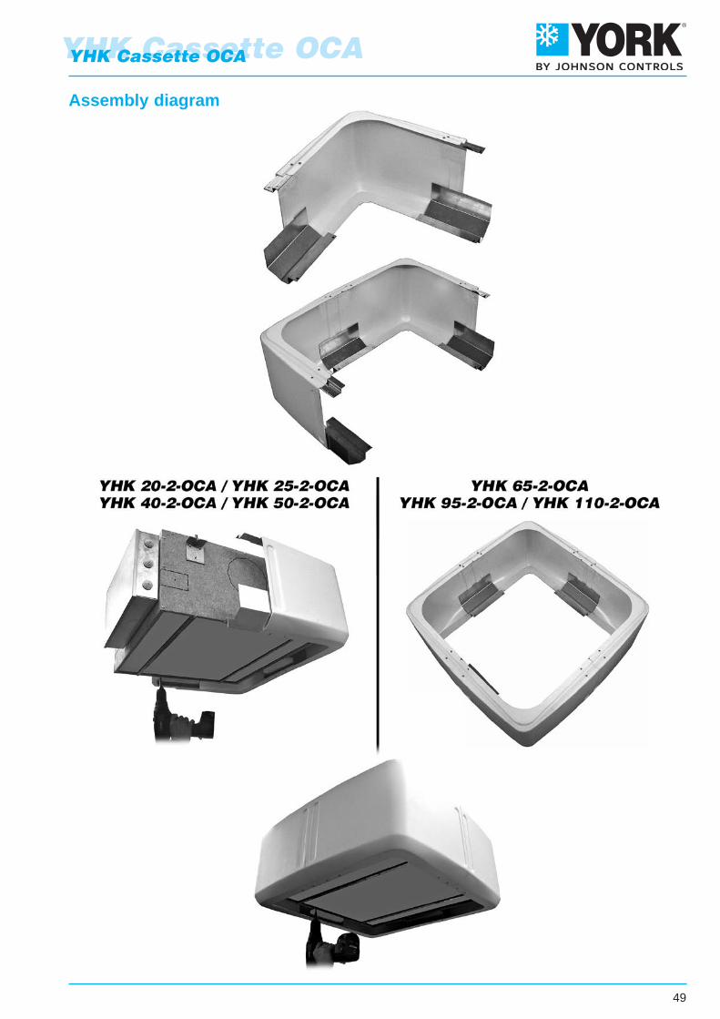
49
YHK Cassette OCAYHK Cassette OCA
Assembly diagram
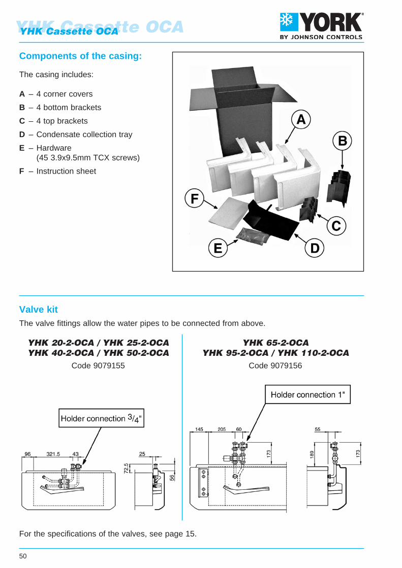
YHK Cassette OCA
50
YHK Cassette OCA
Components of the casing:
Valve kit
The casing includes:
A – 4 corner covers
B – 4 bottom brackets
C – 4 top brackets
D – Condensate collection tray
E – Hardware (45 3.9x9.5mm TCX screws)
F – Instruction sheet
The valve fittings allow the water pipes to be connected from above.
For the specifications of the valves, see page 15.
YHK 20-2-OCA / YHK 25-2-OCAYHK 40-2-OCA / YHK 50-2-OCA
Code 9079155
YHK 65-2-OCAYHK 95-2-OCA / YHK 110-2-OCA
Code 9079156

• Fan absorption • Water pressure drop • Sound power
• Heating emission (2 pipe units) at the following conditions: - Entering water temperature +50°C - Entering air temperature +20°C - Waterflowrateasforthecoolingconditions
• Heating emission (4 pipe units) at the following conditions: - Water temperature +70°C E.W.T. +60°C L.W.T. - Entering air temperature +20°C
• Cooling total emission at the following conditions: - Water temperature +7°C E.W.T. +12°C L.W.T. - Entering air temperature +27°C dry bulb +19°C wet bulb
• Cooling sensible emission at the following conditions: - Water temperature +7°C E.W.T. +12°C L.W.T. - Entering air temperature +27°C dry bulb +19°C wet bulb
The descriptions and illustrations provided in this publication are not binding:Johnson Controls reserve the right, whilst maintaining the essential characteristics
of the types described and illustrated, to make, at any time,without the requirement to promptly update this piece of literature,
any changes that it considers useful for the purposeof improvement or for any other manufacturing or commercial requirements.
CONTENTS
•YHK • Introduction Page 3 • Main components Page 4 • EUROVENT Certifications Page 5 • Emissions Page 6 • Water side pressure drop Page 8 • Working conditions Page 8 • Dimensions and weights Page 10 • Air throw Page 12 • Fresh air supply Page 13 • Air distribution Page 13 • Accessories Page 14 • Wall electronic controls Page 16 • Freewireless control system Page 20 • Unit with infra-red remote control Page 22 • Electric resistance YHK-E Page 25
•YHK–ECM • Introduction Page 26 • Main components Page 27 • EUROVENT Certifications Page 28 • Emissions Page 29 • Water side pressure drop Page 31 • Working conditions Page 31 • Dimensions and weights Page 32 • Air throw Page 34 • Accessories Page 35 • YHKY−ECMconfiguration Page 37 • Wall electronic control Page 38 • YHKH−ECMconfiguration Page 40 • IR remote control with receiver and ETN/ECM control Page 41
•YHK/YHK–ECM • Unit with IR/EC−IRelectronic board Page 43 • Maxinet management system for a network of fan coils Page 44 • Accessories Maxinet 7 Page 46
•YHKCassetteOCA • Introduction Page 47 • Dimensions and weights Page 48 • Assembly diagram Page 49 • Components of the casing Page 50 • Valve kit Page 50
Johnson Controls take part to the Eurovent program of fan coil performance certification.The official figures are published in the web sitewww.eurovent-certification.com and in the web site www.certififlash.com.The tested performances are:
MD-600Version

NEWLow energy
consumption ECM motors
Cassette Fan Coil Units
YHK
- 01
/11
Cod
. A47
9014
2 C
/01/
11
www.eurovent-certification.comwww.certiflash.com
YHKYHK–ECM