yamaha rx-e410 service manual - xdocs.net
TRANSCRIPT
1 0 1 0 1 7
P.O.Box 1, Hamamatsu, Japan
SERVICE MANUAL
DVD-E810
IMPORTANT NOTICE
This manual has been provided for the use of authorized YAMAHA Retailers and their service personnel.
It has been assumed that basic service procedures inherent to the industry, and more specifically YAMAHA Products, are already
known and understood by the users, and have therefore not been restated.
WARNING: Failure to follow appropriate service and safety procedures when servicing this product may result in personal
injury, destruction of expensive components, and failure of the product to perform as specified. For these reasons,
we advise all YAMAHA product owners that any service required should be performed by an authorized
YAMAHA Retailer or the appointed service representative.
IMPORTANT: The presentation or sale of this manual to any individual or firm does not constitute authorization, certification or
recognition of any applicable technical capabilities, or establish a principle-agent relationship of any form.
The data provided is believed to be accurate and applicable to the unit(s) indicated on the cover. The research, engineering, and
service departments of YAMAHA are continually striving to improve YAMAHA products. Modifications are, therefore, inevitable
and specifications are subject to change without notice or obligation to retrofit. Should any discrepancy appear to exist, please
contact the distributor's Service Division.
WARNING: Static discharges can destroy expensive components. Discharge any static electricity your body may have
accumulated by grounding yourself to the ground buss in the unit (heavy gauge black wires connect to this buss).
IMPORTANT: Turn the unit OFF during disassembly and part replacement. Recheck all work before you apply power to the unit.
■ CONTENTSTO SERVICE PERSONNEL ...................................... 2–3
PREVENTION OF ELECTROSTATIC DISCHARGE .... 4
LOCALE MANAGEMENT INFORMATION ................... 4
FRONT PANEL .............................................................. 5
REAR PANELS .............................................................. 5
SPECIFICATIONS...................................................... 6–7
INTERNAL VIEW ........................................................... 7
REPAIR NOTES ............................................................. 7
TRADE MODE ................................................................ 8
DISASSEMBLY PROCEDURES ................................... 9
TEST MODE ................................................................. 10
BLOCK DIAGRAM ....................................................... 11
WIRING DIAGRAM ...................................................... 12
PRINTED CIRCUIT BOARDS................................ 13–16
SCHEMATIC DIAGRAMS ...................................... 17–22
REPLACEMENT PARTS LIST .............................. 24–25
SYSTEM CONTROL .............................................. 26–33
2006 All rights reserved.
This manual is copyrighted by YAMAHA and may not be copied or
redistributed either in print or electronically without permission.
DV
D-E
81
0
'06.08
MICRO COMPONENT SYSTEM MCR-E810DVD PLAYER
The MCR-E810 is composed of the DVD-E810, RX-E810 and NX-E800.
This service manual is for the DVD-E810.
For service manual of the RX-E810 and NX-E800, please refer to the following publication number:
RX-E810/RX-E410/NX-E800 101019
DVD-E810
2
DV
D-E
81
0
■ TO SERVICE PERSONNELWALLOUTLET
EQUIPMENTUNDER TEST
AC LEAKAGETESTER OREQUIVALENT
INSULATINGTABLE
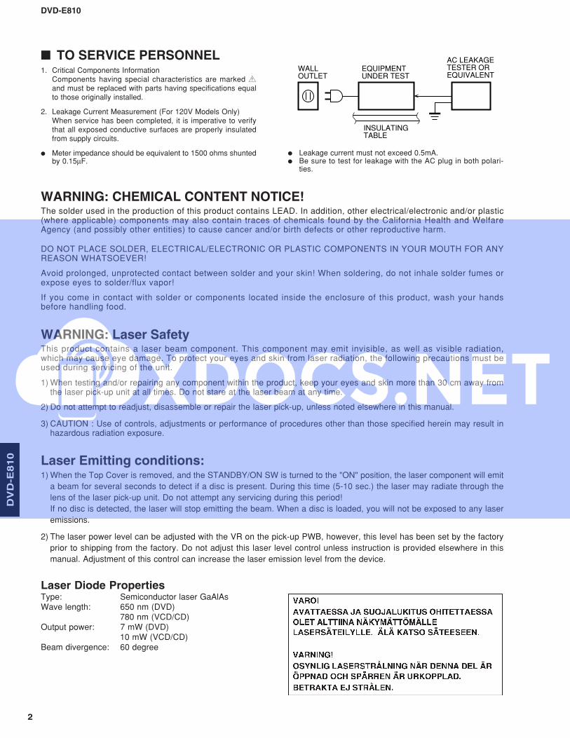
1. Critical Components InformationComponents having special characteristics are marked Zand must be replaced with parts having specifications equalto those originally installed.
2. Leakage Current Measurement (For 120V Models Only)When service has been completed, it is imperative to verifythat all exposed conductive surfaces are properly insulatedfrom supply circuits.
● Meter impedance should be equivalent to 1500 ohms shuntedby 0.15µF.
● Leakage current must not exceed 0.5mA.● Be sure to test for leakage with the AC plug in both polari-
ties.
WARNING: Laser SafetyThis product contains a laser beam component. This component may emit invisible, as well as visible radiation,which may cause eye damage. To protect your eyes and skin from laser radiation, the following precautions must beused during servicing of the unit.
1) When testing and/or repairing any component within the product, keep your eyes and skin more than 30 cm away fromthe laser pick-up unit at all times. Do not stare at the laser beam at any time.
2) Do not attempt to readjust, disassemble or repair the laser pick-up, unless noted elsewhere in this manual.
3) CAUTION : Use of controls, adjustments or performance of procedures other than those specified herein may result inhazardous radiation exposure.
WARNING: CHEMICAL CONTENT NOTICE!The solder used in the production of this product contains LEAD. In addition, other electrical/electronic and/or plastic(where applicable) components may also contain traces of chemicals found by the California Health and WelfareAgency (and possibly other entities) to cause cancer and/or birth defects or other reproductive harm.
DO NOT PLACE SOLDER, ELECTRICAL/ELECTRONIC OR PLASTIC COMPONENTS IN YOUR MOUTH FOR ANYREASON WHATSOEVER!
Avoid prolonged, unprotected contact between solder and your skin! When soldering, do not inhale solder fumes orexpose eyes to solder/flux vapor!
If you come in contact with solder or components located inside the enclosure of this product, wash your handsbefore handling food.
Laser Emitting conditions:1) When the Top Cover is removed, and the STANDBY/ON SW is turned to the "ON" position, the laser component will emit
a beam for several seconds to detect if a disc is present. During this time (5-10 sec.) the laser may radiate through the
lens of the laser pick-up unit. Do not attempt any servicing during this period!
If no disc is detected, the laser will stop emitting the beam. When a disc is loaded, you will not be exposed to any laser
emissions.
2) The laser power level can be adjusted with the VR on the pick-up PWB, however, this level has been set by the factory
prior to shipping from the factory. Do not adjust this laser level control unless instruction is provided elsewhere in this
manual. Adjustment of this control can increase the laser emission level from the device.
Laser Diode PropertiesType: Semiconductor laser GaAlAsWave length: 650 nm (DVD)
780 nm (VCD/CD)Output power: 7 mW (DVD)
10 mW (VCD/CD)Beam divergence: 60 degree
DVD-E810
3
CD
X-4
97
/CD
X-3
97
DV
D-E
81
0
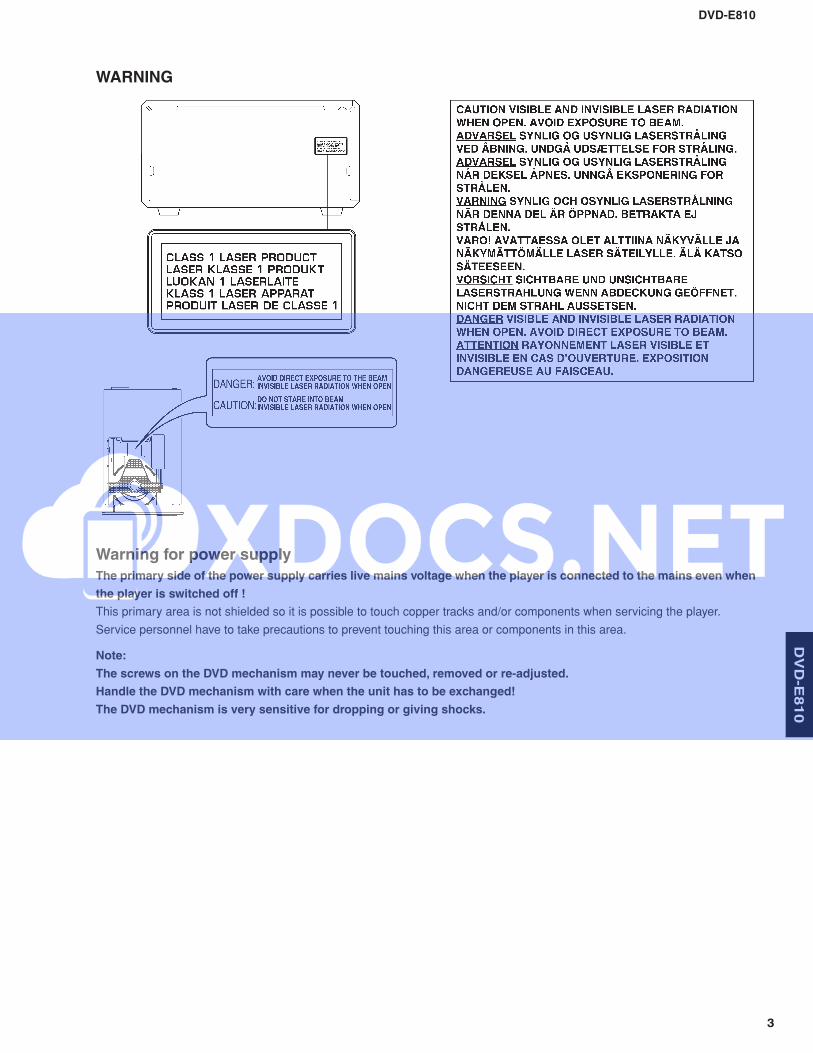
WARNING
Warning for power supply
The primary side of the power supply carries live mains voltage when the player is connected to the mains even when
the player is switched off !
This primary area is not shielded so it is possible to touch copper tracks and/or components when servicing the player.
Service personnel have to take precautions to prevent touching this area or components in this area.
Note:
The screws on the DVD mechanism may never be touched, removed or re-adjusted.
Handle the DVD mechanism with care when the unit has to be exchanged!
The DVD mechanism is very sensitive for dropping or giving shocks.
DVD-E810
4
DV
D-E
81
0
1M-ohms
Conductive material(sheet) or steel sheet
Anti-static wrist strap
1
4
2
2
2
5
5
5
4
3
6
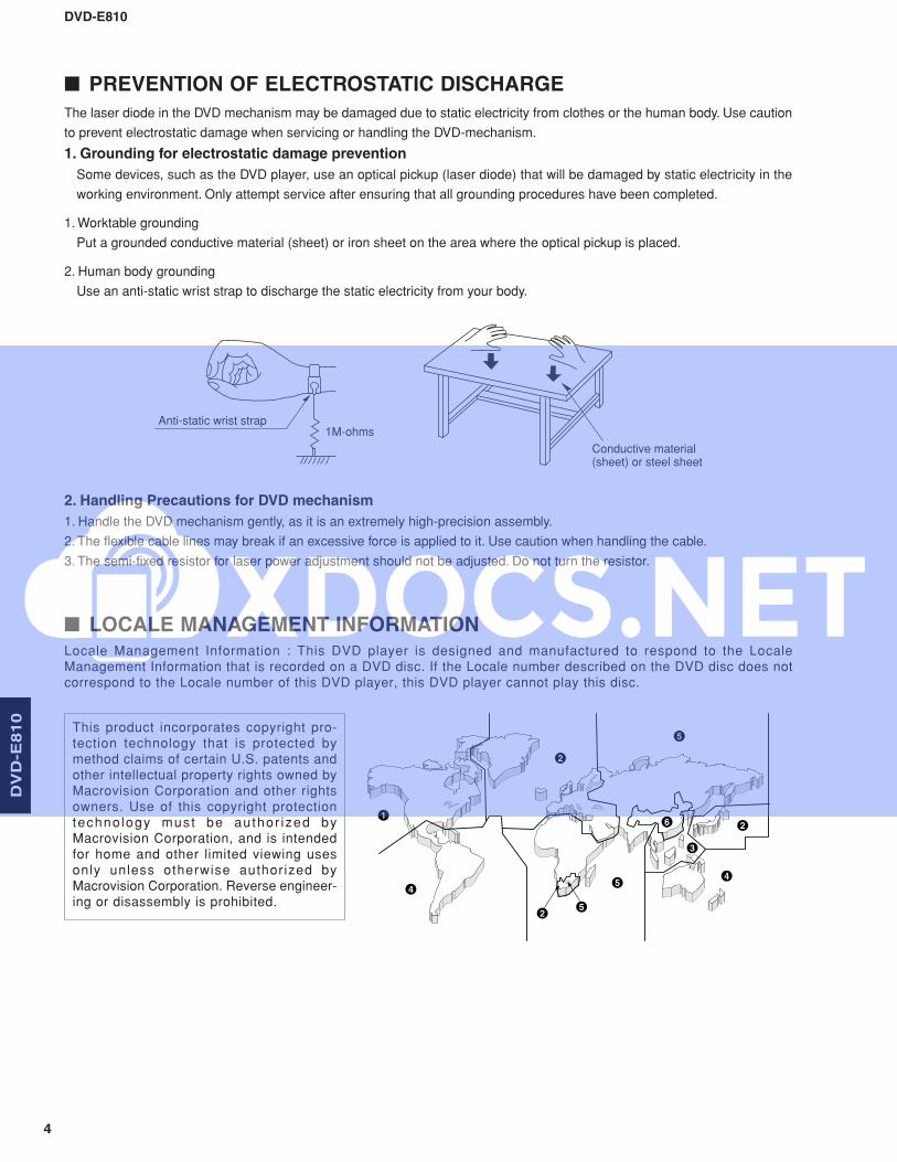
■ PREVENTION OF ELECTROSTATIC DISCHARGE
This product incorporates copyright pro-tection technology that is protected bymethod claims of certain U.S. patents andother intellectual property rights owned byMacrovision Corporation and other rightsowners. Use of this copyright protectiontechno logy must be author ized byMacrovision Corporation, and is intendedfor home and other limited viewing usesonly unless otherwise authorized byMacrovision Corporation. Reverse engineer-ing or disassembly is prohibited.
The laser diode in the DVD mechanism may be damaged due to static electricity from clothes or the human body. Use caution
to prevent electrostatic damage when servicing or handling the DVD-mechanism.
1. Grounding for electrostatic damage prevention
Some devices, such as the DVD player, use an optical pickup (laser diode) that will be damaged by static electricity in the
working environment. Only attempt service after ensuring that all grounding procedures have been completed.
1. Worktable grounding
Put a grounded conductive material (sheet) or iron sheet on the area where the optical pickup is placed.
2. Human body grounding
Use an anti-static wrist strap to discharge the static electricity from your body.
2. Handling Precautions for DVD mechanism
1. Handle the DVD mechanism gently, as it is an extremely high-precision assembly.
2. The flexible cable lines may break if an excessive force is applied to it. Use caution when handling the cable.
3. The semi-fixed resistor for laser power adjustment should not be adjusted. Do not turn the resistor.
■ LOCALE MANAGEMENT INFORMATIONLocale Management Information : This DVD player is designed and manufactured to respond to the LocaleManagement Information that is recorded on a DVD disc. If the Locale number described on the DVD disc does notcorrespond to the Locale number of this DVD player, this DVD player cannot play this disc.
DVD-E810
5
CD
X-4
97
/CD
X-3
97
DV
D-E
81
0
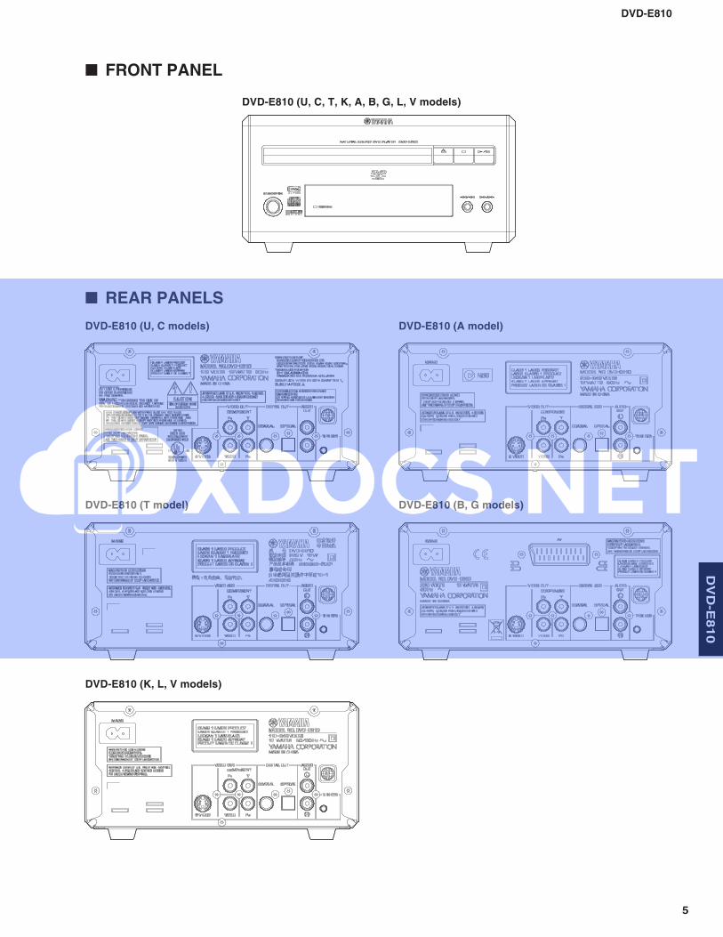
■ FRONT PANEL
■ REAR PANELS
DVD-E810 (U, C, T, K, A, B, G, L, V models)
DVD-E810 (U, C models)
DVD-E810 (T model)
DVD-E810 (K, L, V models)
DVD-E810 (A model)
DVD-E810 (B, G models)
DVD-E810
6
DV
D-E
81
0
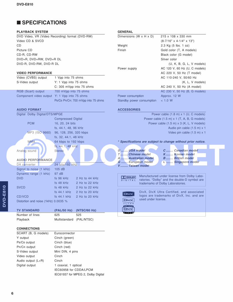
PLAYBACK SYSTEM
DVD Video, VR (Video Recording) format (DVD-RW)
Video CD & SVCD
CD
Picture CD
CD-R, CD-RW
DVD+R, DVD+RW, DVD+R DL
DVD-R, DVD-RW, DVD-R DL
VIDEO PERFORMANCE
Video (CVBS) output 1 Vpp into 75 ohms
S-Video output Y: 1 Vpp into 75 ohms
C: 305 mVpp into 75 ohms
RGB (Scart) output 700 mVpp into 75 ohms
Component video output Y: 1 Vpp into 75 ohms
PB/CB PR/CR: 700 mVpp into 75 ohms
AUDIO FORMAT
Digital Dolby Digital/DTS/MPGE
Compressed Digital
PCM 16, 20, 24 bits
fs, 44.1, 48, 96 kHz
MP3 (ISO 9660) 96, 128, 256, 320 kbps
fs, 32, 44.1, 48 kHz
WMA 64 kbps to 192 kbps
fs, 44.1, 48 kHz
Analog sound Stereo
AUDIO PERFORMANCE
DA converter 24 bits/192 kHz
Signal to noise (1 kHz) 105 dB
Dynamic range (1 kHz) 97 dB
DVD fs 96 kHz 2 Hz to 44 kHz
fs 48 kHz 2 Hz to 22 kHz
SVCD fs 48 kHz 2 Hz to 22 kHz
fs 44.1 kHz 2 Hz to 20 kHz
CD/VCD fs 44.1 kHz 2 Hz to 20 kHz
Distortion and noise (1kHz) 0.0035 %
TV STANDARD (PAL/50 Hz) (NTSC/60 Hz)
Number of lines 625 525
Playback Multistandard (PAL/NTSC)
CONNECTIONS
SCART (B, G models) Euroconnector
Y output Cinch (green)
PB/CB output Cinch (blue)
PR/CR output Cinch (red)
S-Video output Mini DIN, 4 pins
Video output Cinch
Audio output (L+R) Cinch
Digital output 1 coaxial, 1 optical
IEC60958 for CDDA/LPCM
IEC61937 for MPEG 2, Dolby Digital
GENERAL
Dimensions (W x H x D) 215 x 108 x 330 mm
(8-7/16" x 4-1/4" x 13")
Weight 2.3 Kg (5 lbs. 1 oz)
Finish Gold color (T, A models)
Black color (G model)
Silver color
(U, K, B, G, L, V models)
Power supply AC 120 V, 60 Hz (U, C models)
AC 220 V, 50 Hz (T model)
AC 110-240 V, 50/60 Hz
(K, L, V models)
AC 240 V, 50 Hz (A model)
AC 230 V, 50 Hz (B, G models)
Power consumption Approx. 12 W
Standby power consumption < 1.0 W
ACCESSORIES
Power cable (1.8 m) x 1 (U, C models)
Power cable (1.5 m) x 1 (T, A, B, G models)
Power cable (1.5 m) x 3 (K, L, V models)
Audio pin cable (1.5 m) x 1
Video pin cable (1.5 m) x 1
* Specifications are subject to change without prior notice.
U ........ USA model C ........ Canadian model
T ......... Chinese model K ........ Korean model
A ........ Australian model B ........ British model
G ........ European model L ........ Singapore model
V ......... Taiwan model
■ SPECIFICATIONS
DivX, DivX Ultra Certified, and associatedlogos are trademarks of DivX, Inc. and areused under license.
Manufactured under license from Dolby Labo-ratories. “Dolby” and the double-D symbol aretrademarks of Dolby Laboratories.
DVD-E810
7
CD
X-4
97
/CD
X-3
97
DV
D-E
81
0
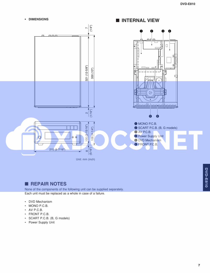
Unit: mm (inch)
• DIMENSIONS
None of the components of the following unit can be supplied separately.
Each unit must be replaced as a whole in case of a failure.
• DVD Mechanism
• MONO P.C.B.
• AV P.C.B.
• FRONT P.C.B.
• SCART P.C.B. (B, G models)
• Power Supply Unit
■ REPAIR NOTES
■ INTERNAL VIEW
215 (8-7/16")
100 (
3-1
5/1
6")
8
(5/1
6")
108 (
4-1
/4")
321 (
12-5
/8")
2
(1/1
6")
7
(1/4
")330 (
13")
6
2
5
1 3 4
MONO P.C.B.
SCART P.C.B. (B, G models)
AV P.C.B.
Power Supply Unit
DVD Mechanism
FRONT P.C.B.
1
2
3
4
5
6
DVD-E810
8
DV
D-E
81
0
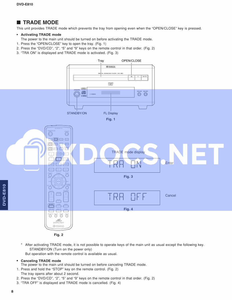
■ TRADE MODEThis unit provides TRADE mode which prevents the tray from opening even when the “OPEN/CLOSE” key is pressed.
• Activating TRADE mode
The power to the main unit should be turned on before activating the TRADE mode.
1. Press the “OPEN/CLOSE” key to open the tray. (Fig. 1)
2. Press the “DVD/CD”, “2”, “5” and “9” keys on the remote control in that order. (Fig. 2)
3. “TRA ON” is displayed and TRADE mode is activated. (Fig. 3)
* After activating TRADE mode, it is not possible to operate keys of the main unit as usual except the following key.
STANDBY/ON (Turn on the power only)
But operation with the remote control is available as usual.
• Canceling TRADE modeThe power to the main unit should be turned on before canceling TRADE mode.
1. Press and hold the “STOP” key on the remote control. (Fig. 2)
The tray opens after about 2 second.
2. Press the “DVD/CD”, “2”, “5” and “9” keys on the remote control in that order. (Fig. 2)
3. “TRA OFF” is displayed and TRADE mode is cancelled. (Fig. 4)
Fig. 1
Fig. 2
TRADE mode display
Fig. 3
Fig. 4
Enter
Cancel
STANDBY/ON FL Display
Tray OPEN/CLOSE
DVD-E810
9
Optical Pick Up
Solder
Tray
Rear
Slider
Screw Driver
Front
Bottoma
c
b
CN1 CN3
CN101
1201
1206
1207
1302 (B, G models)
1800
1812
11011102
1103Power Supply Unit
MONO P.C.B.
FRONT P.C.B.DVD Mechanism
SCART P.C.B. (B, G models)
AV P.C.B.
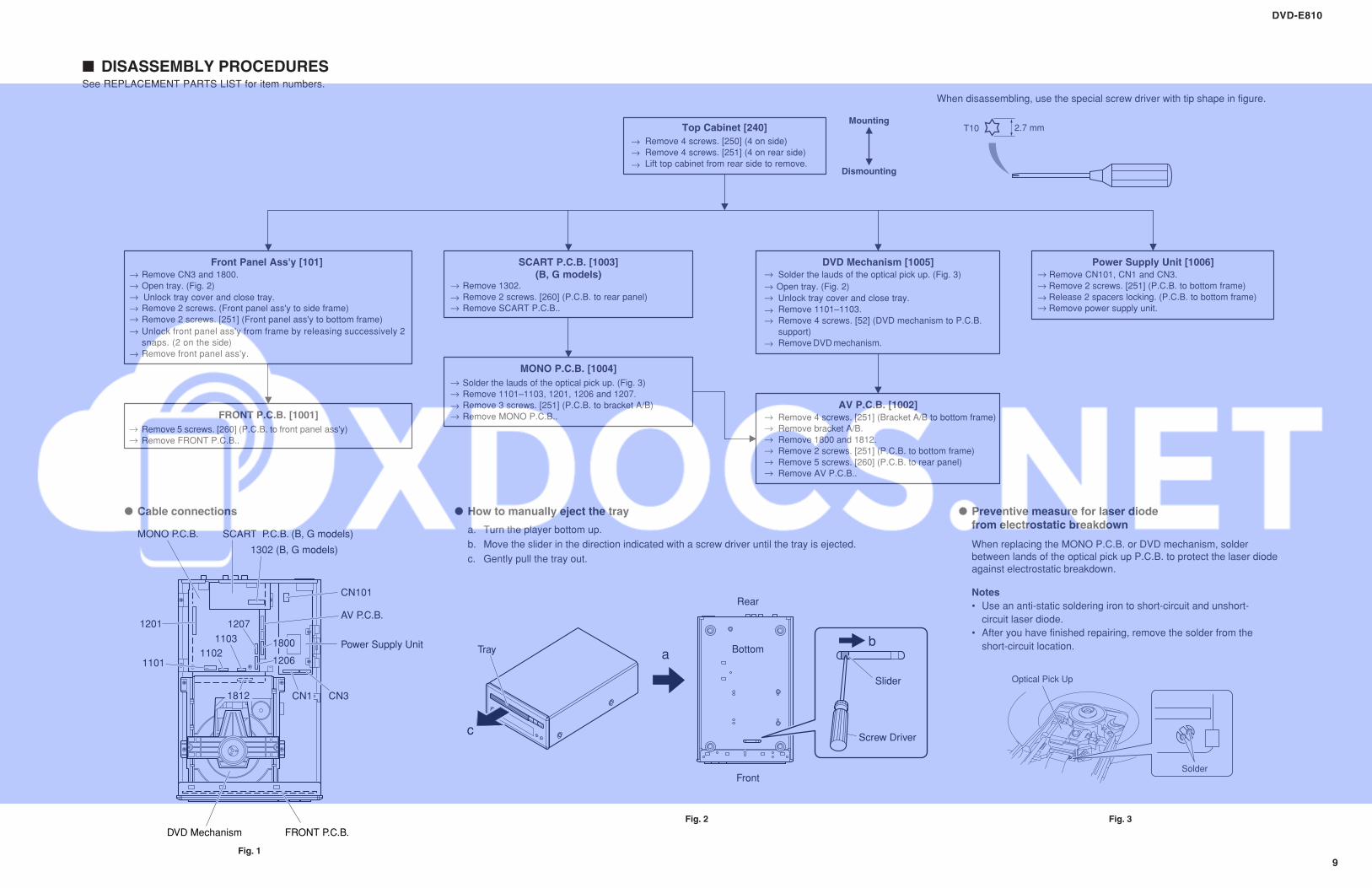
Top Cabinet [240]
Remove 4 screws. [250] (4 on side)
Lift top cabinet from rear side to remove.
SCART P.C.B. [1003]
(B, G models)
Power Supply Unit [1006]
Remove CN101, CN1 and CN3.
Remove 2 screws. [251] (P.C.B. to bottom frame)
Release 2 spacers locking. (P.C.B. to bottom frame)
Remove power supply unit.
FRONT P.C.B. [1001]
Remove 5 screws. [260] (P.C.B. to front panel ass'y)
Front Panel Ass'y [101]
Remove CN3 and 1800.
Open tray. (Fig. 2)
Remove 2 screws. (Front panel ass'y to side frame)
Remove 2 screws. [251] (Front panel ass'y to bottom frame)
Unlock front panel ass'y from frame by releasing successively 2
snaps. (2 on the side)
Mounting
Dismounting
2.7 mm
When disassembling, use the special screw driver with tip shape in figure.
T10
Remove FRONT P.C.B..
Remove 4 screws. [251] (4 on rear side)
Remove 1302.
Remove 2 screws. [260] (P.C.B. to rear panel)
Remove SCART P.C.B..
MONO P.C.B. [1004]
Solder the lauds of the optical pick up. (Fig. 3)
Remove 1101–1103, 1201, 1206 and 1207.
Remove 3 screws. [251] (P.C.B. to bracket A/B)
Remove MONO P.C.B..
DVD Mechanism [1005]
Solder the lauds of the optical pick up. (Fig. 3)
Unlock tray cover and close tray.
Remove 4 screws. [52] (DVD mechanism to P.C.B.
support)
AV P.C.B. [1002]
Remove 4 screws. [251] (Bracket A/B to bottom frame)
Remove bracket A/B.
Remove 1800 and 1812.
Remove 2 screws. [251] (P.C.B. to bottom frame)
Remove 5 screws. [260] (P.C.B. to rear panel)
Remove AV P.C.B..
Remove 1101–1103.
Remove DVD mechanism.Remove front panel ass'y.
How to manually eject the tray
a. Turn the player bottom up.
When replacing the MONO P.C.B. or DVD mechanism, solder
between lands of the optical pick up P.C.B. to protect the laser diode
against electrostatic breakdown.
b. Move the slider in the direction indicated with a screw driver until the tray is ejected.
c. Gently pull the tray out.
Preventive measure for laser diode
from electrostatic breakdown
Cable connections
Notes
• Use an anti-static soldering iron to short-circuit and unshort-
circuit laser diode.
• After you have finished repairing, remove the solder from the
short-circuit location.
Fig. 1
Fig. 2 Fig. 3
Unlock tray cover and close tray.Open tray. (Fig. 2)
■ DISASSEMBLY PROCEDURESSee REPLACEMENT PARTS LIST for item numbers.
DVD-E810
10
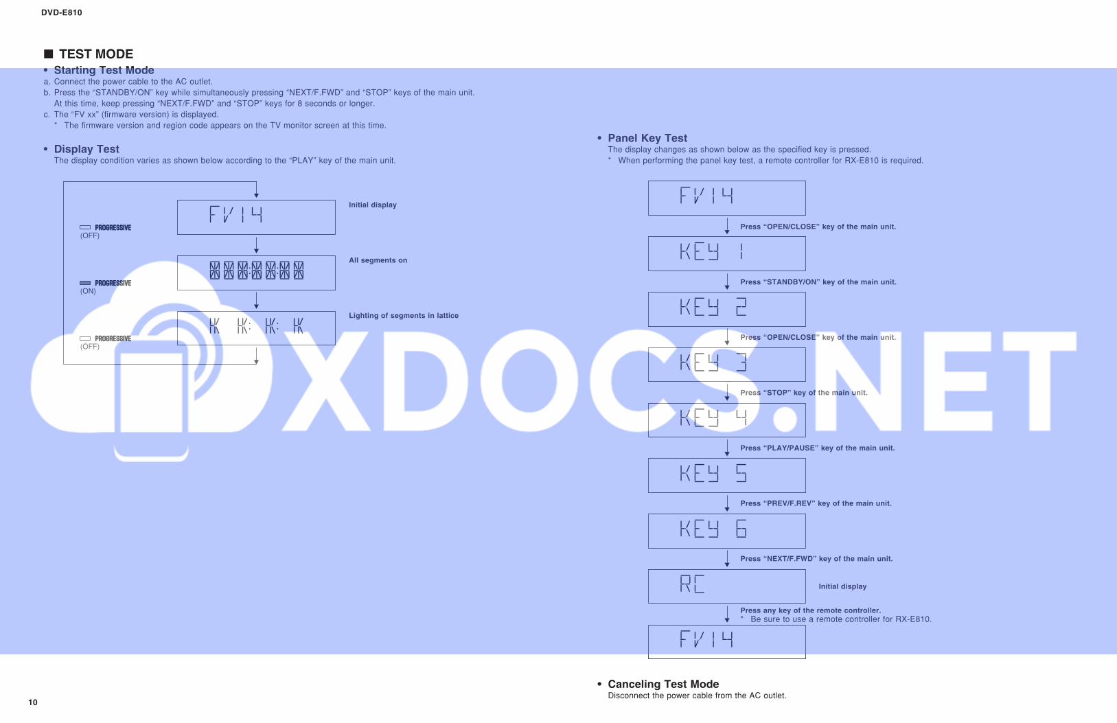
■ TEST MODE
• Starting Test Modea. Connect the power cable to the AC outlet.
b. Press the “STANDBY/ON” key while simultaneously pressing “NEXT/F.FWD” and “STOP” keys of the main unit.
At this time, keep pressing “NEXT/F.FWD” and “STOP” keys for 8 seconds or longer.
c. The “FV xx” (firmware version) is displayed.
* The firmware version and region code appears on the TV monitor screen at this time.
• Display TestThe display condition varies as shown below according to the “PLAY” key of the main unit.
• Panel Key TestThe display changes as shown below as the specified key is pressed.
* When performing the panel key test, a remote controller for RX-E810 is required.
Initial display
Initial display
All segments on
Lighting of segments in lattice
(OFF)
(OFF)
(ON)
• Canceling Test ModeDisconnect the power cable from the AC outlet.
Press “OPEN/CLOSE” key of the main unit.
Press “STANDBY/ON” key of the main unit.
Press “OPEN/CLOSE” key of the main unit.
Press “STOP” key of the main unit.
Press “PLAY/PAUSE” key of the main unit.
Press “PREV/F.REV” key of the main unit.
Press “NEXT/F.FWD” key of the main unit.
Press any key of the remote controller.
* Be sure to use a remote controller for RX-E810.