xyz turret mill prototrak emx cnc
TRANSCRIPT
XYZXYZ Turret Mill
ProtoTRAK EMX CNC Safety, Programming, Operating & Care Manual
Covers Models:
XYZ EMX XYZ EMX 2000 XYZ EMX 3000
XYZ Machine Tools Ltd. Woodlands Business Park Bur lescombe, Tiverton, Devon EX16 7LL T: 01823 674200 F: 01823 674201 e-mai l: sa [email protected] www.xyzmachinetools.com
Document: 26075 Version: 043015

Copyright © 2015 XYZ Machine Tools, Ltd. All rights are reserved. No part of this publication may be reproduced, stored in a retrieval system, or transmitted, in any form or by any means, mechanical, photocopying, recording or otherwise, without the prior written permission of XYZ Machine Tools, Ltd. While every effort has been made to include all the information required for the purposes of this guide, XYZ Machine Tools assumes no responsibility for inaccuracies or omission and accepts no liability for damages resulting from the use of the information contained in this guide. All brand names and products are trademarks or registered trademarks of their respective holders. XYZ Machine Tools Woodlands Business Park Burlescombe, Nr Tiverton Devon, EX16 7LL Service Department Tel: 01823 674214 Fax: 01823 674201

i XYZ Machine Tools Ltd
XYZ Turret Mill & ProtoTRAK® EMX CNC Safety, Programming, Operating & Care Manual
Table of Contents 1.0 Introduction 1 1.1 Conditions of this manual 1.2 Manual Organisation 2.0 Safety 2 2.1 Introduction 2.2 Safe Operating Information 2.3 Release of Trapped Persons 2.4 EC Declaration of Conformity 2.5 Safety Notices Used in this Manual 3.0 Description 11 3.1 Prototrak EMX CNC Specifications 3.2 Display Pendant 3.3 Mill Specifications 3.4 Auto Lube System 3.5 Servo Motors 3.6 Ballscrews 3.7 Electrical Cabinet 3.8 Z Scale 3.9 Work Light 3.10 Coolant Pump 3.11 Swarf Tray 3.12 Table Guard 3.13 Optional Equipment 3.14 Spindle Motor 4.0 Basic Operation 20 4.1 Prototrak EMX Basic Operation 4.2 Machine Operation 5.0 Definition, Terms & Concepts 26 5.1 ProtoTRAK Axis Conventions 5.2 Absolute and Incremental Refs 5.3 Referenced & Non Ref Data 5.4 Tool Diameter Compensation 5.5 Connective Events 5.6 Conrad 5.7 Memory and Storage 6.0 DRO Mode 29 6.1 Enter DRO Mode 6.2 DRO Functions 6.3 Jog 6.4 Return to Abs Zero 6.5 Power Feed 6.6 Changing between Inch and mm Display 6.7 Service codes 7.0 Program Mode 32 7.1 Enter Program Mode & Assign Program Name 7.2 Programming strategy and Procedures 7.3 Programming Events 7.4 Prompts used to Define Events 7.5 Continue 7.6 Assumed Inputs 7.7 Incremental reference Position 7.8 Finish Cuts 7.9 Look 7.10 A Sample Program
8.0 Changing/Correcting Programs 40 8.1 Deleting a Partially Programmed Event 8.2 Editing Data while Programming an Event 8.3 Editing Previously Programmed Events 8.4 Changing the Feedrate 8.5 Changing a Part Number 8.6 Saving Changes to a Program 8.7 Erasing an Entire Program 9.0 Making Parts with the CNC 42 9.1 Setting Up 9.2 Starting 9.3 Display Messages in Program Run 9.4 Program Run Prompts 9.5 Stop 9.6 Feedrate Override 9.7 Trail Run 9.8 Data Errors 9.9 Fault Messages 10.0 Math Help 44 10.1 Procedure 10.2 Math Help Types 11.0 Program Memory and Storage 47 11.1 Cautions on Opening and Deleting Programs 11.2 Program Formats and Labeling 11.3 Saving & Opening Programs 11.4 File Transfer and Backup 12.0 Service Codes 50 12.1 Service Code Procedure 12.2 Service Code Types 13.0 Prototrak EMX Tutorial 52 13.1 Working with Definitions, Terms & Conventions 13.2 Basic Operation 13.3 Programming Sample 14.0 Additional Sample Programs 67 14.1 Program # 1 14.2 Program # 2 14.3 Program # 3 14.4 Program # 4 14.5 Program # 5
1 XYZ Machine Tools Ltd.
XYZ Turret Mill & ProtoTRAK EMX CNC Safety, Programming, Operating & Care Manual
1.0 Introduction Congratulations on your purchase of the finest toolroom turret mill available today. The ProtoTRAK EMX CNC gives you the power and flexibility to work your own way, while performing at a high level of productivity. Manual Machining is always available and made easier with features like power feed, 2500 mm per minute rapids, and all the best features of sophisticated DRO’s. Two-Axis Machining is available at the touch of a button for the prototyping and moderately complex, low volume work that is typically done on turret mills. The operation of the ProtoTRAK EMX CNC has been painstakingly refined to bring you the most useful CNC technology while retaining the ease of use that has made ProtoTRAK the top brand in controls for low volume production.
This manual will describe the operation of all basic and optional features in the appropriate context. Where optional features are discussed, a note will explain in which option the particular feature is found.
1.1 Conditions Of This Manual
All details contained in this manual are accurate at the time of going to press, E & OA, but please be aware that XYZ Machine Tools has a policy of continuous development, and because of this some details are subject to change without prior notice. Please be sure to confirm any important specifications and details prior to ordering.
1.2 Manual Organisation
This manual covers the operation of the XYZ turret mill products that use the ProtoTRAK EMX CNC.
Please note Section 2 of this manual provides important safety information. It is essential that all operators of this product review this safety information carefully.
2XYZ Machine Tools Ltd
XYZ Turret Mill & ProtoTRAK EMX CNC Safety, Programming, Operating & Care Manual
2.0 Safety 2.1 Introduction
Manual mills were traditionally used by skilled machinists. Prototrak was designed to replace these manual machines and at the same time enhance productivity by adding CNC control.
But, unlike Machining and Turning Centres that can be operated even with unskilled staff (in some modes), Prototrak was designed to be used by skilled, experienced machinists.
The safe operation of the EMX Mill and ProtoTRAK EMX CNC depends on its proper use and the precautions taken by the machinist.
2.2 Safe Operating Information
This machine is designed for the milling of cold metal within the stated capacity of the mill with axes movement occurring by manual use of handwheels or CNC control.
This machine must not be used for machining flammable materials (e.g. magnesium) without undertaking a risk assessment and incorporating any additional safety measures identified.
It is designed to be used in a standard workshop environment only.
It is the responsibility of the employer, machine owner or machine controller to ensure that this machine is installed, operated and maintained in accordance with the Provision and Use of Work Equipment Regulations (1998) or equivalent local regulations.
In particular, the responsible person must: Undertake a Risk Assessment on the use of this machine, paying particular attention to the
specific characteristics of the Prototrak control system (for example, operating mode selection and access to the work zone)
Generate and apply Safe Operating Procedures for the use of the Prototrak machine Provide any additional training or safeguarding identified by the risk assessment.
All operators must read and study this ProtoTRAK EMX CNC Safety, Programming, Operating, and Care Manual. The machine must not be used until operators understand the operation and safety requirements of this machine.
This machine must only be operated by trained and experienced operators. Any other users should first be subjected to a risk assessment by a responsible, trained person.
The cutting tool must not be raised above the table guards without additional guarding measures such as a cutter guard (for example if riser blocks are fitted to the machine).
The guard vision panels must be replaced in accordance with the stated schedule.
When operating this machine, always observe the following safety precautions
Do not operate this machine without knowing the function of every control key, button, knob, or handle.
Always wear the appropriate personal protective equipment, including safety glasses and safety shoes.
Do not wear loose fitting gloves whilst operating this machine as they could easily get caught in moving parts.
Never wear rings, watches, long sleeves, neckties, jewelry, or other loose items when operating the machine.
3XYZ Machine Tools Ltd
XYZ Turret Mill & ProtoTRAK EMX CNC Safety, Programming, Operating & Care Manual
Keep your hair away from moving parts. Wear adequate safety head gear.
Never operate any machine tool after consuming alcoholic beverages, or taking strong medications, or while using non-prescription drugs.
Carry out a COSHH risk assessment and use the correct protection equipment, e.g. barrier cream/latex gloves, to prevent harm from items such as cutting fluid, lubrication oil and other substances used on the machine.
Always ensure the appropriate guarding is in place for the machinery operation being undertaken.
Observe and understand the warning and safety information labels affixed to this machine.
Do not attempt to tamper with or override any guarding/safety device fitted to the machine.
Keep the working area clear and remove all tools (spanners etc.) from the machine before you start the machine running. Loose items can become dangerous flying projectiles.
Stop the machine spindle and ensure that the CNC control is in the STOP mode:
o Before changing tools.
o Before changing parts.
o Before you clear away the Swarf, oil or coolant. Always use a chip scraper or brush.
o Before you make an adjustment to the part, vice, coolant nozzle or take measurements.
o Before you open guards. Never reach around a guard to gain access to the part, tool, or fixture.
Do not use compressed air to remove swarf or clean the machine.
Keep work area well lit. Ask for additional light if needed.
Be aware that the machine can move unexpectedly so do not lean on the machine while it is running.
To prevent slippage and personal injury, keep the working area around the machine dry and clean. Ensure there is no swarf, oil, coolant and obstacles of any kind around the machine.
Avoid getting pinched in places where the spindle, table or guard doors create "pinch points" whilst the machine is in motion.
To prevent injury during powered axes movement, keep the handwheel handle folded away at all times except when required to hand crank the table.
Securely clamp and properly locate the workpiece in the vice or in a fixture. Use proper tool holding equipment.
Use the correct tooling for the process being undertaken. Never use damaged or worn tools and ensure the correct cutting parameters (speed, feed, and depth of cut) are used in order to prevent tool breakage.
Prevent damage to the workpiece or the cutting tool. Never start the machine (including the rotation of the spindle) if the tool is in contact with the part.
Avoid large overhangs on cutting tools when not necessary.
To prevent fires keep flammable materials and fluids away from the machine, hot swarf and workpieces.
Never change gears when the spindle is rotating
Do not rotate the spindle by hand unless the table guard is open.
Stop and disconnect the power to the machine before undertaking any machine cleaning or maintenance

4XYZ Machine Tools Ltd
XYZ Turret Mill & ProtoTRAK EMX CNC Safety, Programming, Operating & Care Manual
2.3 Release of Trapped Persons.
In the event of persons being trapped in the machine:
1. Hit the E-Stop button to kill all power to the spindle and axes.
2. Open the table guards.
3. If trapped by spindle or tool, remove the compressed air supply to the machine and rotate the spindle by hand to free the trapped person.
4. If trapped by the axes, use the manual handwheels to move the axes slowly clear of the trapped person.
2.4 EC Declaration of Conformity
The manufacturer, Southwestern Industries, declares that the EMX series of Turret Mills conform to all the relevant provisions of the:
• Machinery Directive 2006/42/EC • Low Voltage Directive 2014/35/EU, and • EMC Directive 2004/108/EC
The Technical file is available from XYZ Machine Tools, Woodlands Business Park, Burlescombe, Nr Tiverton, EX16 7LL, United Kingdom.

5XYZ Machine Tools Ltd
XYZ Turret Mill & ProtoTRAK EMX CNC Safety, Programming, Operating & Care Manual
2.5 Danger, Warning, Caution, and Note Labels and Notices Used in this Manual
DANGER - Immediate hazards that will result in severe personal injury or death. Danger labels on the machine are red in color.
WARNING - Hazards or unsafe practices that could result in severe personal injury and/or damage to the equipment. Warning labels on the machine are amber in color.
CAUTION - Hazards or unsafe practices that could result in minor personal injury or equipment/product damage. Caution labels on the machine are Yellow in color.
NOTE - Call attention to specific issues requiring special attention or understanding.
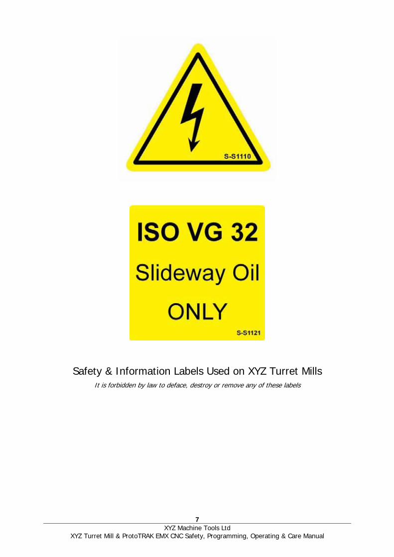
Safety & Information Labels Used on XYZ Turret Mills It is forbidden by law to deface, destroy or remove any of these labels

6XYZ Machine Tools Ltd
XYZ Turret Mill & ProtoTRAK EMX CNC Safety, Programming, Operating & Care Manual
Safety & Information Labels Used on XYZ Turret Mills It is forbidden by law to deface, destroy or remove any of these labels
7XYZ Machine Tools Ltd
XYZ Turret Mill & ProtoTRAK EMX CNC Safety, Programming, Operating & Care Manual
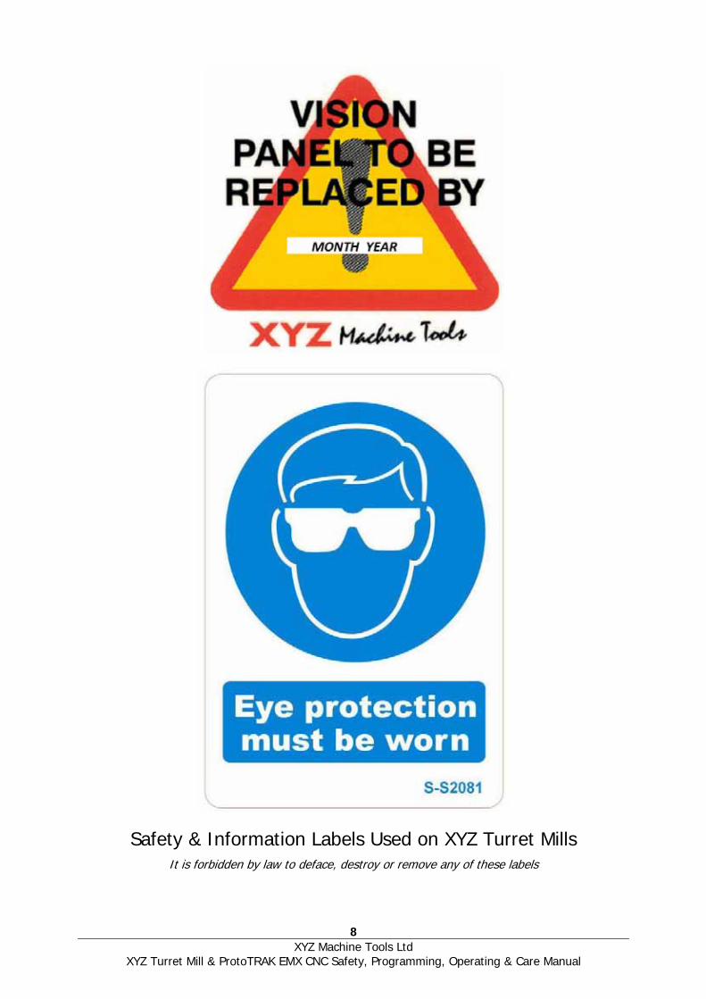
Safety & Information Labels Used on XYZ Turret Mills It is forbidden by law to deface, destroy or remove any of these labels
8XYZ Machine Tools Ltd
XYZ Turret Mill & ProtoTRAK EMX CNC Safety, Programming, Operating & Care Manual
Safety & Information Labels Used on XYZ Turret Mills It is forbidden by law to deface, destroy or remove any of these labels
9XYZ Machine Tools Ltd
XYZ Turret Mill & ProtoTRAK EMX CNC Safety, Programming, Operating & Care Manual
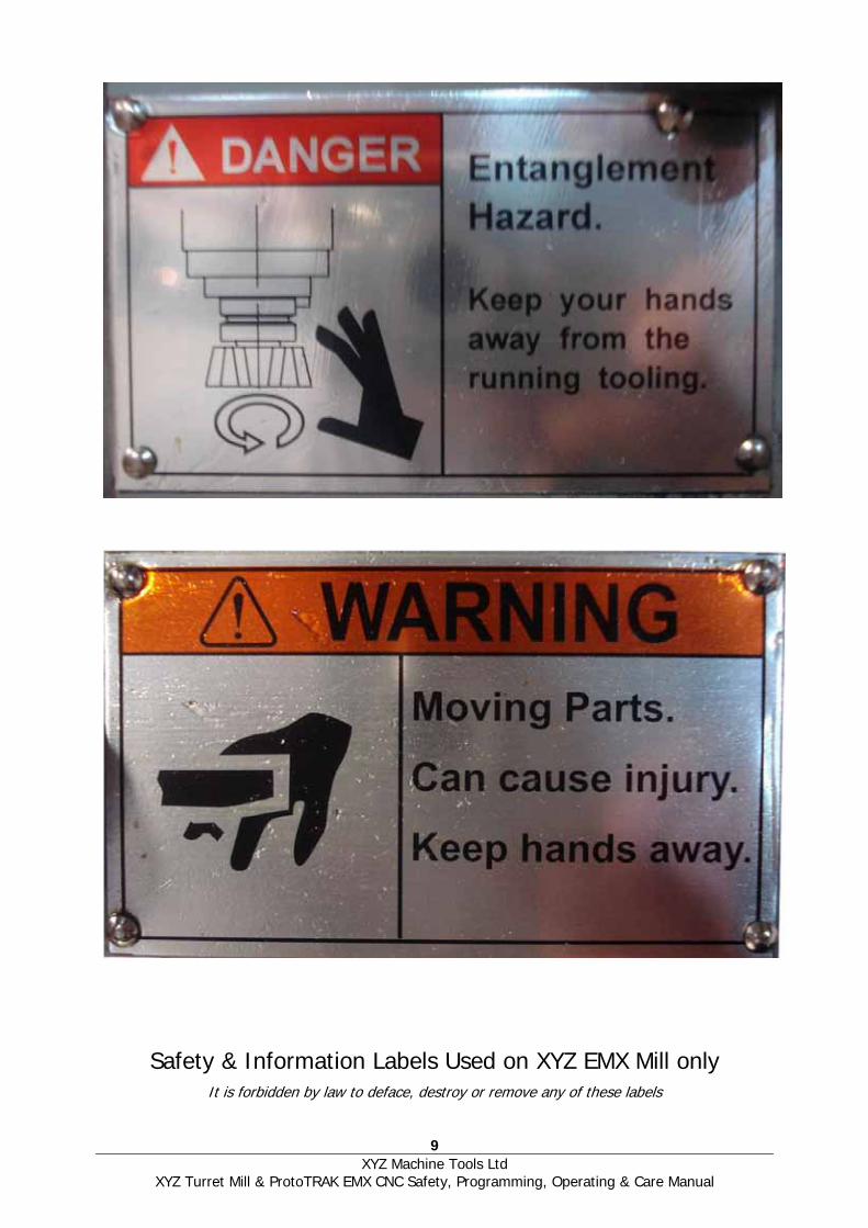
Safety & Information Labels Used on XYZ EMX Mill only It is forbidden by law to deface, destroy or remove any of these labels
10XYZ Machine Tools Ltd
XYZ Turret Mill & ProtoTRAK EMX CNC Safety, Programming, Operating & Care Manual
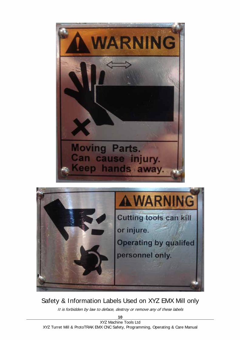
Safety & Information Labels Used on XYZ EMX Mill only It is forbidden by law to deface, destroy or remove any of these labels
11 XYZ Machine Tools, Ltd.
XYZ Turret Mill & ProtoTRAK EMX CNC Safety, Programming, Operating & Care Manual
3.0 Description 3.1 ProtoTRAK EMX CNC Specifications The list below summarises the features and specifications. Each feature is described in more detail in the appropriate section of the manual.
3.1.1 Basic System Specifications Control Hardware Digital Servo Amplifiers – custom designed for ProtoTRAK operation D.C. Servo Motors – rated at 2 Nm continuous torque; twice that required Precision Ball Screws – in the table and saddle Modular Design – simplifies service and maximized uptime Feedrate Override of programmed feedrate and rapid Polycarbonate Sealed Membrane Keypad to lock out contamination 7.0” Color LCD On board IDE flash memory storage for part programs USB port for interface with a storage device Rugged Industrial PC Glass Scale on quill for Z-axis readout
Software Diameter Cutter Compensation – allows programming of the part rather than the centre
of the tool path Circular interpolation – makes arcs and any size hole easy to do with standard
tools Linear Interpolation – to machine lines at any angle Conrad – provides automatic corner radius programming with one data input Incremental and Absolute – programming can even be mixed within an event Error Messages – to identify programming mistakes Fault Messages – for system self-diagnostics Parts Graphics display Look – a single button press to view graphics during programming Math Help – for finding points in a prompted format with graphical representation of
prompts Machine Tool Error Compensation and Backlash Compensation custom set on mill after
installation Selectable Inch/mm measurement readout Jog of X and Y from 25.4 mm to 2540 mm per minute Continue Mill to eliminate repetitive data input while programming Context help information provides explanations of ProtoTRAK EMX operations
Programmed Canned Cycles Posn/Drill – single point Bolt Hole – series of points evenly spaced around a circle Mill – straight line in any direction Arc – any portion of a circle Pocket – a rectangle or circle and all the material inside, includes finish cut Frame – a perimeter of a rectangle or circle, includes finish cut Repeat – of programmed events with or without offset
Options Remote Stop/Go (RSG) switch Free offline EMX programming system (download from XYZ website).

12 XYZ Machine Tools, Ltd.
XYZ Turret Mill & ProtoTRAK EMX CNC Safety, Programming, Operating & Care Manual
3.2 Display Pendant 3.2.1 Front
Keyboard Hard Keys
GO: initiates motion in Run
STOP: halts motion during Run
LOOK: part graphics in Program mode INC/ABS: switches all or one axis between incremental and absolute
INC SET: loads incremental dimensions and general data
ABS SET: loads absolute dimensions and general data
X, Y, Z: selects axis for subsequent commands
0-9, +/-, . : inputs numeric data with floating point format. Data are automatically + unless +/- key is pressed. All input data are automatically rounded to the system's resolution.
MODE: to change from one mode of operation to another
HELP: displays information about the operation of each mode.
RESTORE: clears an entry
Arrow Keys Between the LCD Screen and the hard keys is a column of arrow keys. Up key, down key: these are located at the top and bottom of the column, respectively. They have several uses:
feedrate override in Run and DRO modes page forward, page back to move through events in a program data forward, data back to move through the data in an event
13 XYZ Machine Tools, Ltd.
XYZ Turret Mill & ProtoTRAK EMX CNC Safety, Programming, Operating & Care Manual
Middle five keys: These keys are called software programmable or soft keys. A description of the function or use of each of these keys will be shown on the LCD screen next to each key. If, at any time, there is no description above a key, that key will not operate. Emergency Stop Switch The emergency stop (E-stop) switch kills all power to the ProtoTRAK's servomotors and spindle. The pendant remains powered.
The Liquid Crystal Display (LCD) The display of the ProtoTRAK EMX is a 7” active-matrix color LCD. The information displayed on the LCD screen is nearly always divided into 4 sections or areas.
1. The top line, or status line, shows the system's current status. This includes the mode, inch or mm measurement, and part numbers.
2. Beneath the status line, and filling most of the screen, is the information area. Position data, program data, and graphics are shown here. In addition message windows will be here in the information area.
3. Beneath the information area is a single "conversation" line. When numeric data are required the conversation line will appear for you to see the numbers you enter before they are set into the system.
4. On the right side of the LCD are boxes describing the current function or use of each soft key located next to them.
3.2.2 Pendant Back Panel
Description of Connections: X-Motor and Y-Motor
The X and Y motor cables are plugged in here.
WARNING! Never plug or unplug motor cables with the power on. This will destroy the computer!
14 XYZ Machine Tools, Ltd.
XYZ Turret Mill & ProtoTRAK EMX CNC Safety, Programming, Operating & Care Manual
Z Scale Plug in the Z scale cable.
Table Guard For plugging in the interlock switch that is part of the table guard.
The USB Ports There are two USB ports, use only one at a time for a thumb drive for program storage, transferring programs between ProtoTRAKs and computers, and for program backup. Software updates will be through the USB port. The thumb drives listed below proved to be compatible with the ProtoTRAK EMX CNC at the time of writing. We cannot guarantee that the brands won’t change in some way that makes them incompatible, but they are known to work now.
PNY Memorex Lexar Microadvantage Delkin / E Film Test port Used by the factory for testing only. GND (Ground) The pendant is grounded via the AC inlet, but additional grounding may be attached here.
AC Inlet To plug in 110v power from the electrical cabinet. An on/off switch is located directly below this inlet.

15 XYZ Machine Tools, Ltd.
XYZ Turret Mill & ProtoTRAK EMX CNC Safety, Programming, Operating & Care Manual
3.3 Mill Specifications
See Figures 3.3.1 and 3.3.2.
FIGURE 3.3.1 Typical XYZ Turret Mill front view

16 XYZ Machine Tools, Ltd.
XYZ Turret Mill & ProtoTRAK EMX CNC Safety, Programming, Operating & Care Manual
FIGURE 3.3.2 Typical XYZ Turret Mill back view
17 XYZ Machine Tools Ltd.
XYZ Turret Mill & ProtoTRAK EMX CNC Safety, Programming, Operating & Care Manual
CNC Turret Mill Specifications XYZ EMX XYZ EMX 2000 XYZ EMX 3000
Table Size 1067 x 230 1270 x 254 1371 x 305 T-Slots 3 3 3 Table Travel 762 762 813 Saddle Travel 305 406 431 Knee Travel 406 406 406 Ram Travel 305 450 450 Maximum Quill Travel, 2-axis CNC
120 127 127
Quill Diameter 85.7 86 105 Spindle Taper R8 R8 40 ISO Spindle Speed 60 – 3500 75 - 4200 70 – 3600 Head Tilt fore & aft 45 – 45 45 - 45 45 – 45 Head Tilt left - right 90 - 90 90 - 90 90 - 90 Spindle Motor Power 3 HP 3 HP 5 HP Power requirements, machine 16 Amp 16 Amp 20 Amp Maximum Weight on Table 350 Kg 350 Kg 550 Kg Machine Weight 1000 Kg 1250 Kg 1650 Kg Machine dims l, w, h 1600 x 1450 2200 3220 x 2580 x 2180 3670 x 2690 x 2340 Max rapid feed X,Y 2500 2500 2500 Way surface type Hardened Box Way Hard chrome V way Hardened Box way Precision 7207 CP4 spindle bearings Chrome hardened and ground quill Meehanite castings Slide ways are Turcite coated Wide way surfaces are hardened and ground.
3.4 Auto Lubrication System The way and ballscrew lubrication are supplied by a pump located on the side of the machine. The interval and discharge time of the pump are set by XYZ Machine Tools should not be changed or altered, otherwise your warranty will become invalid.
After periods of non-operation of the machine we recommend that before you operate the machine you first press the pump button located on the pump itself. This will ensure that adequate lubrication is supplied to key parts of the machine before you start.
Factory Default Values Interval Time – 50 min Discharge Time – 5 sec Discharge Pressure – Approximately 100 – 150psi
CAUTION! Failure to properly lubricate the mill will result in the premature failure of
bearings and sliding surfaces.
CAUTION! Failure to manually activate the pump at the beginning of each day, or allowing the Auto Lube
to run dry may cause severe damage to the mill’s way surfaces and ballscrews.
Head Lubrication Once Each Week:
1. Fill the oil cup on the front of the head with ISO 32 oil. This oil lubricates the Hi/Lo range shifter.

18 XYZ Machine Tools Ltd.
XYZ Turret Mill & ProtoTRAK EMX CNC Safety, Programming, Operating & Care Manual
2. Fill the ball oiler located in the front lower right corner of the speed hanger housing. This oil lubricates the speed changer shaft.
3. Extend the quill fully and apply a coating of ISO 32 oil to the outside diameter of the quill.
Every Four Months:
Apply a good grade of general-purpose grease through the grease fittings on the back of the head and on the left side of the head. The grease lubricates the low range gear set and the feed change gears respectively.
3.5 Servo Motors The servo motors on the table and saddle are rated at 2 Nm of torque. Integrated into each motor is a servo amplifier and an encoder with 0.9 µm underlying resolution for all models.
3.6 Ballscrews Precision ground ballscrews are installed in the table and saddle to ensure smooth traverse and positive control for manual and CNC machining.
3.7 Electrical Cabinet An electrical cabinet is mounted on the side of the column. A 400V, 3 phase and earth supply is required into the cabinet.
3.8 Z Axis Feedback Scale For two-axis CNC models, a Z-axis feedback scale is mounted either to the quill or the knee in order to provide digital readout of the Z axis position.
3.9 Work Light A halogen work light is supplied with the machine. It mounts to the left side (facing) of the column.
3.10 Coolant Pump The coolant pump is mounted in the back of the machine column. It is controlled from a push button switch on the switch panel adjacent to the pendant.
3.11 Swarf Tray The swarf Tray fits around the base of the mill to collect coolant and swarf (option for XYZ EMX).
3.12 Table Guard The Table guard provides an enclosed workspace mounted on the table. The doors are switched to prevent the machine spindle starting in any mode if they are open. It also prevents the operation of the CNC in Run mode with the door open. While it will aid in the control of swarf and coolant, it is not a full, waterproof enclosure. Removal of these guards is prohibited by law. They are fitted for the benefit of the machine operator and to comply with the current legislation, removal means you are breaking the law.
3.13 Optional Equipment 3.13.1 Power Draw Bar A manual draw bar comes as standard with the machine. A power draw bar option may be ordered. For EMX 2000, and XYZ EMX, the drawbar is for an R8 spindle. For the EMX 3000 the draw bar included in the option is for a #40 ISO spindle.
The standard type of power draw bar is of the appropriate length to fit tool holders that have a threaded tang on the top (ISO 40). BT40 and CAT 40 tool holders have a different

19 XYZ Machine Tools Ltd.
XYZ Turret Mill & ProtoTRAK EMX CNC Safety, Programming, Operating & Care Manual
arrangement at the small tapered end so a longer drawbar is required to thread into the tool holder when the retention knob is removed. These longer drawbars can be provided on request please talk to your Area Sales Manager or XYZ Machine Tools parts department.
3.13.2 Remote Stop Go Switch For the convenience of operation while running the program, a Remote Stop/Go switch may be purchased. This switch is on a 2 metre, coiled cable and operates like the FEED STOP and GO keys on the display.
3.13.3 USB Thumb Drive A USB Thumb Drive is available to:
Save program files for backing up or additional storage Load program files Share program files between ProtoTRAKs or computers Save backup system configuration files, including backlash and calibration values
3.14 Spindle Motor The spindle motor runs at a fixed speed. Spindle speed is set by selecting high or low gear and adjusting the vari-speed belt drive system.
20 XYZ Machine Tools Ltd.
XYZ Turret Mill & ProtoTRAK EMX CNC Safety, Programming, Operating & Care Manual
4.0 Basic Operation The ProtoTRAK EMX CNC combines the simplicity and flexibility of using a turret mill with the easy, natural user interface that makes the ProtoTRAK the top brand in CNCs for small lot machining.
4.1 ProtoTRAK EMX Basic Operation. 4.1.1 Switching the ProtoTRAK EMX CNC on and off Turn the ProtoTRAK EMX System on by moving the on-off rocker switch located directly under the power cord. The switch may be left on and the control turned on and off using the main machine isolator. When it is first turned on the system will display a series of boot-up screens while the ProtoTRAK EMX system loads. To turn off the system, simply flip the toggle switch. It is not necessary to do a shutdown routine.
4.1.2 Screen Saver If the system is not used (either by a keystroke or by counting) for 20 continuous minutes, the LCD will turn itself off. Press any key to bring the screen back to its previous display. The key you press will be ignored except to turn the screen on.
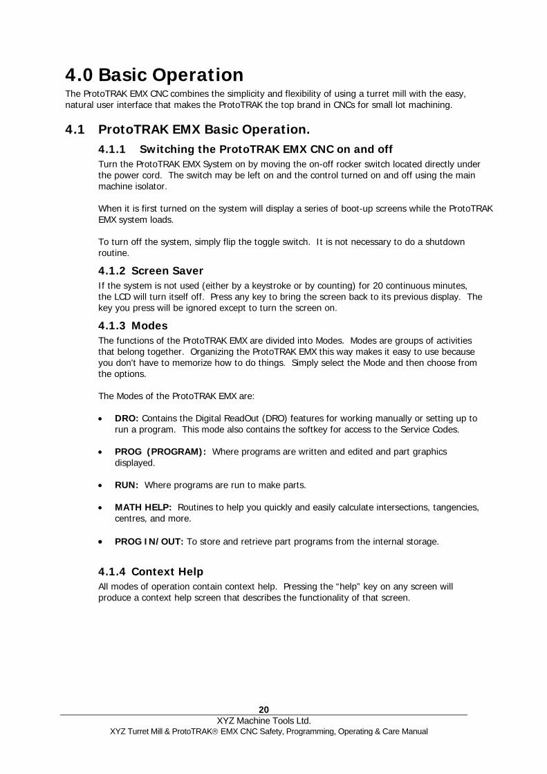
4.1.3 Modes The functions of the ProtoTRAK EMX are divided into Modes. Modes are groups of activities that belong together. Organizing the ProtoTRAK EMX this way makes it easy to use because you don't have to memorize how to do things. Simply select the Mode and then choose from the options. The Modes of the ProtoTRAK EMX are: DRO: Contains the Digital ReadOut (DRO) features for working manually or setting up to
run a program. This mode also contains the softkey for access to the Service Codes.
PROG (PROGRAM): Where programs are written and edited and part graphics displayed.
RUN: Where programs are run to make parts.
MATH HELP: Routines to help you quickly and easily calculate intersections, tangencies, centres, and more.
PROG IN/OUT: To store and retrieve part programs from the internal storage.
4.1.4 Context Help All modes of operation contain context help. Pressing the “help” key on any screen will produce a context help screen that describes the functionality of that screen.
21 XYZ Machine Tools Ltd.
XYZ Turret Mill & ProtoTRAK EMX CNC Safety, Programming, Operating & Care Manual
4.1.5 Emergency Stop Press the button to shut off power to the axes motors and spindle motor. Rotate the switch to release.
4.2 Machine Operation 4.2.1 Switch Panel Controls The switch panel is mounted to the left of the pendant and houses the following controls:
POWER ON Button: o Enables power to the machine equipment; including the axes motors, coolant
pump and powered drawbar (option). o Press this button to energise the machine whenever the machine is first
switched on, or after an emergency stop. COOLANT Pushbutton:
o Press to turn the coolant pump on o Press again to turn the coolant pump off
SPINDLE RESET: o Push to enable the spindle o Press this button to enable the spindle whenever the machine is first switched
on, or after the table guards are opened or after an emergency stop o For all models except XYZ EMX, this button must be pressed to reset the
spindle after the spindle switch is turned off o For model XYZ EMX, the spindle cannot be reset unless at least 50 psi of air
pressure is available at the air inlet (to operate the spindle brake). SPINDLE FWD/REV/OFF
o Turn the Spindle switch to left for forward (clockwise) spindle rotation if the Hi-Lo-Neutral lever is in the low position.
o Turn the Spindle switch right for forward (clockwise) spindle rotation if the Hi-Lo-Neutral lever is in the high position.
o Return the Spindle switch to the vertical position to turn the spindle off.
22 XYZ Machine Tools Ltd.
XYZ Turret Mill & ProtoTRAK EMX CNC Safety, Programming, Operating & Care Manual
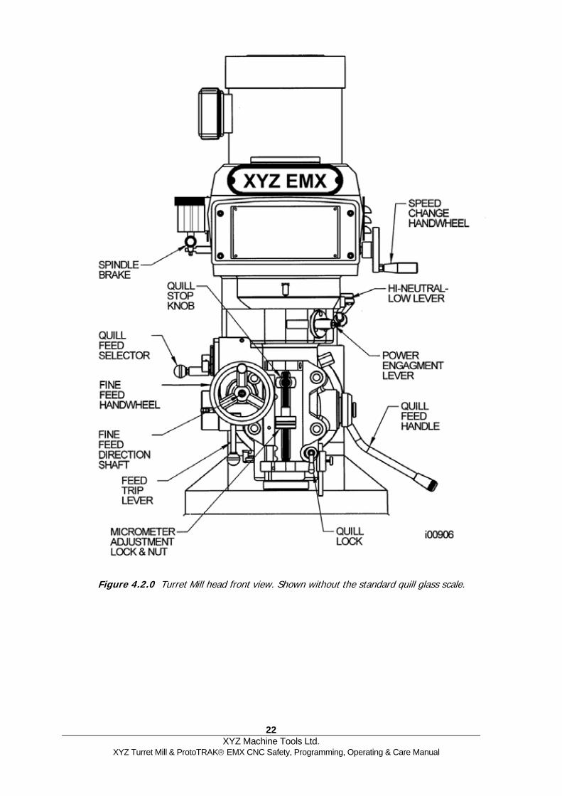
Figure 4.2.0 Turret Mill head front view. Shown without the standard quill glass scale.
23 XYZ Machine Tools Ltd.
XYZ Turret Mill & ProtoTRAK EMX CNC Safety, Programming, Operating & Care Manual
4.2.2 Raising/Lowering the Knee The knee is raised and lowered using the hand crank located on the left front of the knee. Clockwise rotation moves the knee up, whilst anti-clockwise rotation moves the knee down.
Be sure the turret is unclamped before raising or lowering.
4.2.3 Spindle Brake The spindle brake is operated automatically whenever the spindle is turned off.
4.2.4 Draw Bar The draw bar holds the tool holders into the spindle taper. The bar has an M16 right hand thread and should be tightened with a 23mm spanner from the top of the head. If the tool holder does not release from the spindle, lightly tap on the top of the bar to dislodge the tool.
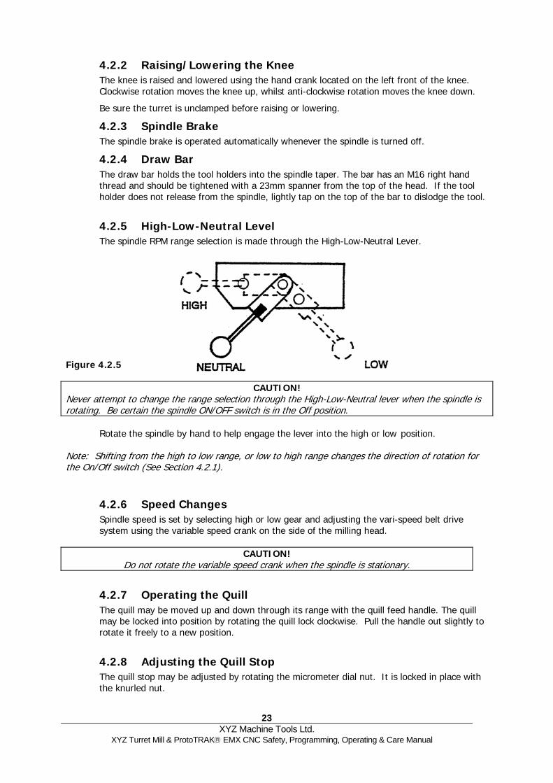
4.2.5 High-Low-Neutral Level The spindle RPM range selection is made through the High-Low-Neutral Lever.
Figure 4.2.5
CAUTION! Never attempt to change the range selection through the High-Low-Neutral lever when the spindle is rotating. Be certain the spindle ON/OFF switch is in the Off position.
Rotate the spindle by hand to help engage the lever into the high or low position.
Note: Shifting from the high to low range, or low to high range changes the direction of rotation for the On/Off switch (See Section 4.2.1).
4.2.6 Speed Changes Spindle speed is set by selecting high or low gear and adjusting the vari-speed belt drive system using the variable speed crank on the side of the milling head.
CAUTION! Do not rotate the variable speed crank when the spindle is stationary.
4.2.7 Operating the Quill The quill may be moved up and down through its range with the quill feed handle. The quill may be locked into position by rotating the quill lock clockwise. Pull the handle out slightly to rotate it freely to a new position.
4.2.8 Adjusting the Quill Stop The quill stop may be adjusted by rotating the micrometer dial nut. It is locked in place with the knurled nut.

24 XYZ Machine Tools Ltd.
XYZ Turret Mill & ProtoTRAK EMX CNC Safety, Programming, Operating & Care Manual
4.2.9 Power Feed Engagement Lever
The power feed is engaged or disengaged with this selector. Pull out the knob and rotate it clockwise to disengage power feed. Rotate it counterclockwise to engage power feed.
i00166
Figure 4.2.9
CAUTION!
It is recommended that the selector be disengaged when the spindle is not running. Never have the feed engaged when the spindle RPM is over 3000. Always leave the selector in the disengaged
position unless the feed function is being used.
4.2.10 Fine Feed Direction Shaft
The direction of the fine feed is set by the position of the fine feed direction shaft. IN sets the direction down, OUT sets the direction up, and NEUTRAL in the middle.
i00166
Figure 4.2.10
25 XYZ Machine Tools Ltd.
XYZ Turret Mill & ProtoTRAK EMX CNC Safety, Programming, Operating & Care Manual
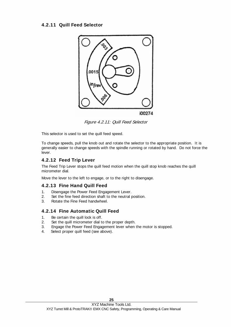
4.2.11 Quill Feed Selector
Figure 4.2.11: Quill Feed Selector
This selector is used to set the quill feed speed.
To change speeds, pull the knob out and rotate the selector to the appropriate position. It is generally easier to change speeds with the spindle running or rotated by hand. Do not force the lever.
4.2.12 Feed Trip Lever The Feed Trip Lever stops the quill feed motion when the quill stop knob reaches the quill micrometer dial.
Move the lever to the left to engage, or to the right to disengage.
4.2.13 Fine Hand Quill Feed 1. Disengage the Power Feed Engagement Lever. 2. Set the fine feed direction shaft to the neutral position. 3. Rotate the Fine Feed handwheel.
4.2.14 Fine Automatic Quill Feed 1. Be certain the quill lock is off. 2. Set the quill micrometer dial to the proper depth. 3. Engage the Power Feed Engagement lever when the motor is stopped. 4. Select proper quill feed (see above).
26 XYZ Machine Tools Ltd.
XYZ Turret Mill & ProtoTRAK EMX CNC Safety, Programming, Operating & Care Manual
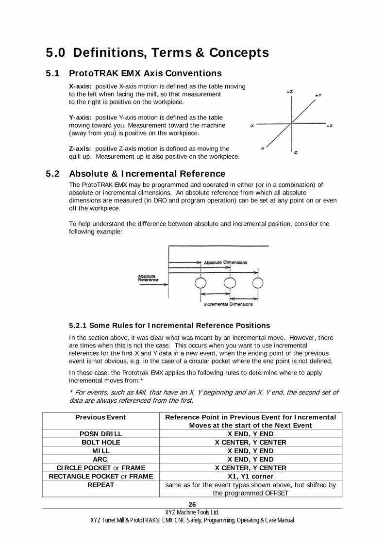
5.0 Definitions, Terms & Concepts 5.1 ProtoTRAK EMX Axis Conventions
X-axis: positive X-axis motion is defined as the table moving to the left when facing the mill, so that measurement to the right is positive on the workpiece. Y-axis: positive Y-axis motion is defined as the table moving toward you. Measurement toward the machine (away from you) is positive on the workpiece. Z-axis: positive Z-axis motion is defined as moving the quill up. Measurement up is also positive on the workpiece.
5.2 Absolute & Incremental Reference The ProtoTRAK EMX may be programmed and operated in either (or in a combination) of absolute or incremental dimensions. An absolute reference from which all absolute dimensions are measured (in DRO and program operation) can be set at any point on or even off the workpiece. To help understand the difference between absolute and incremental position, consider the following example:
5.2.1 Some Rules for Incremental Reference Positions
In the section above, it was clear what was meant by an incremental move. However, there are times when this is not the case. This occurs when you want to use incremental references for the first X and Y data in a new event, when the ending point of the previous event is not obvious, e.g. in the case of a circular pocket where the end point is not defined.
In these case, the Prototrak EMX applies the following rules to determine where to apply incremental moves from:*
* For events, such as Mill, that have an X, Y beginning and an X, Y end, the second set of data are always referenced from the first.
Previous Event Reference Point in Previous Event for Incremental
Moves at the start of the Next Event POSN DRILL X END, Y END BOLT HOLE X CENTER, Y CENTER
MILL X END, Y END ARC, X END, Y END
CIRCLE POCKET or FRAME X CENTER, Y CENTER RECTANGLE POCKET or FRAME X1, Y1 corner
REPEAT same as for the event types shown above, but shifted by the programmed OFFSET
27 XYZ Machine Tools Ltd.
XYZ Turret Mill & ProtoTRAK EMX CNC Safety, Programming, Operating & Care Manual
5.3 Referenced and Non-Referenced Data Data are always loaded into the ProtoTRAK EMX by using the INC SET or ABS SET key. X, Y, Z positions are referenced data. In entering any X, Y, or Z position data, you must note whether they are incremental or absolute dimensions and enter them accordingly. All other information (non-referenced data), such as tool diameter, feedrate, etc. is not a position and may, therefore, be loaded with either the INC SET or ABS SET key. This manual uses the term SET when either INC SET or ABS SET may be used interchangeably.
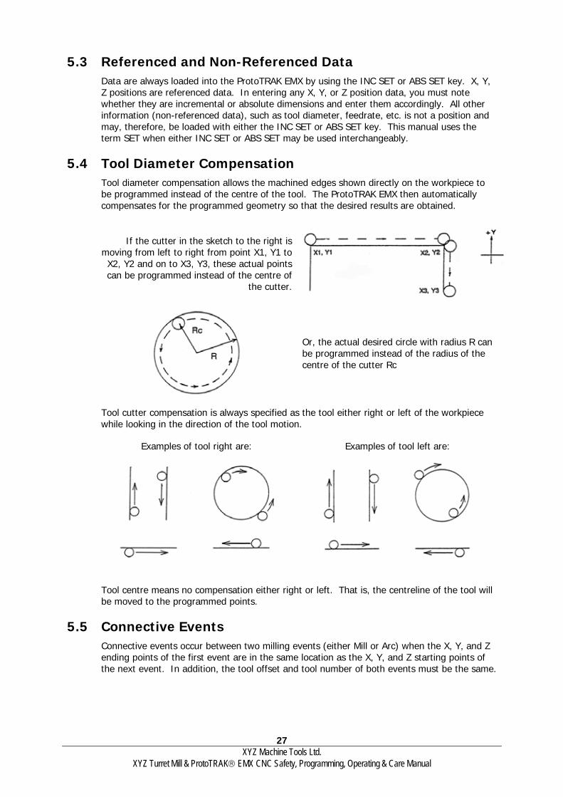
5.4 Tool Diameter Compensation Tool diameter compensation allows the machined edges shown directly on the workpiece to be programmed instead of the centre of the tool. The ProtoTRAK EMX then automatically compensates for the programmed geometry so that the desired results are obtained.
If the cutter in the sketch to the right is moving from left to right from point X1, Y1 to X2, Y2 and on to X3, Y3, these actual points can be programmed instead of the centre of
the cutter.
Or, the actual desired circle with radius R can be programmed instead of the radius of the centre of the cutter Rc
Tool cutter compensation is always specified as the tool either right or left of the workpiece while looking in the direction of the tool motion.
Examples of tool right are: Examples of tool left are:
Tool centre means no compensation either right or left. That is, the centreline of the tool will be moved to the programmed points.
5.5 Connective Events Connective events occur between two milling events (either Mill or Arc) when the X, Y, and Z ending points of the first event are in the same location as the X, Y, and Z starting points of the next event. In addition, the tool offset and tool number of both events must be the same.
28 XYZ Machine Tools Ltd.
XYZ Turret Mill & ProtoTRAK EMX CNC Safety, Programming, Operating & Care Manual
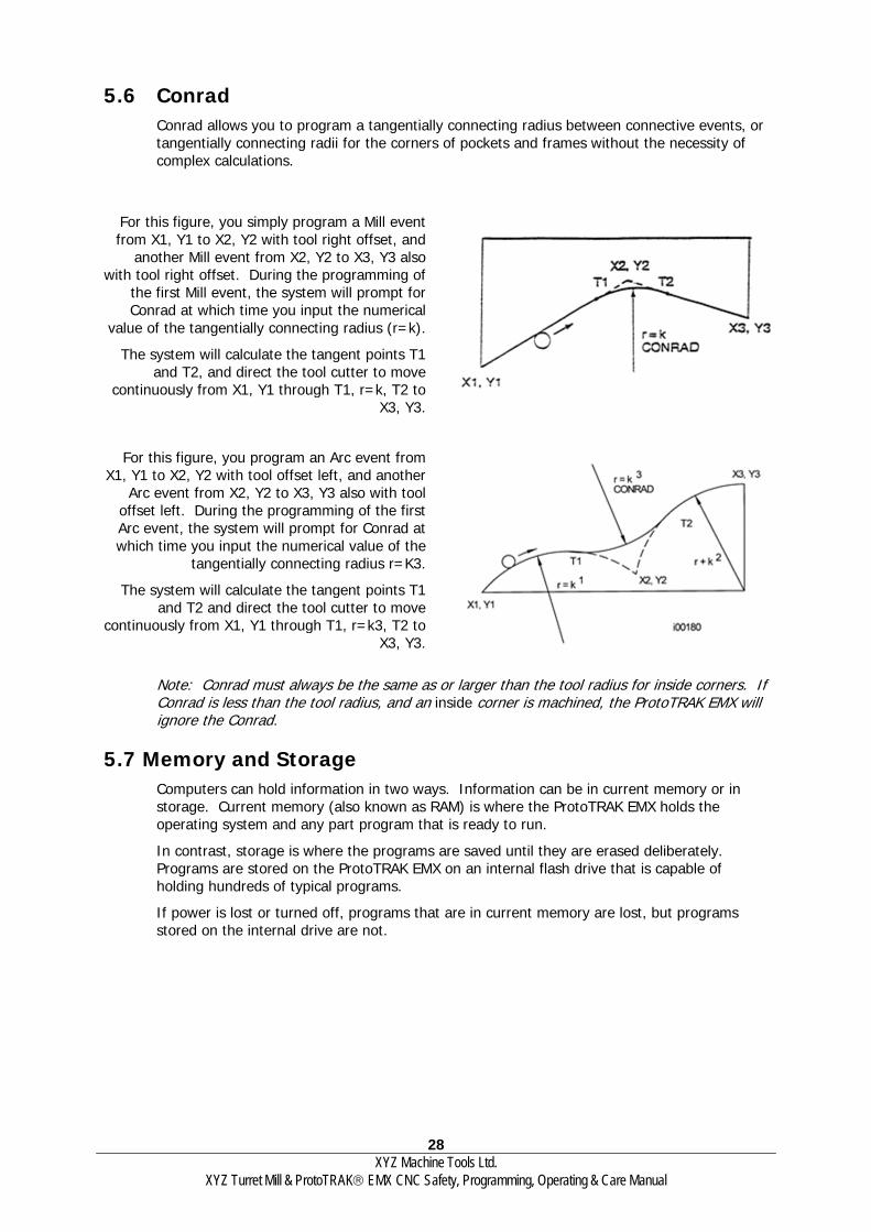
5.6 Conrad Conrad allows you to program a tangentially connecting radius between connective events, or tangentially connecting radii for the corners of pockets and frames without the necessity of complex calculations.
For this figure, you simply program a Mill event from X1, Y1 to X2, Y2 with tool right offset, and
another Mill event from X2, Y2 to X3, Y3 also with tool right offset. During the programming of
the first Mill event, the system will prompt for Conrad at which time you input the numerical
value of the tangentially connecting radius (r=k).
The system will calculate the tangent points T1 and T2, and direct the tool cutter to move
continuously from X1, Y1 through T1, r=k, T2 to X3, Y3.
For this figure, you program an Arc event from X1, Y1 to X2, Y2 with tool offset left, and another
Arc event from X2, Y2 to X3, Y3 also with tool offset left. During the programming of the first Arc event, the system will prompt for Conrad at which time you input the numerical value of the
tangentially connecting radius r=K3.
The system will calculate the tangent points T1 and T2 and direct the tool cutter to move
continuously from X1, Y1 through T1, r=k3, T2 to X3, Y3.
Note: Conrad must always be the same as or larger than the tool radius for inside corners. If Conrad is less than the tool radius, and an inside corner is machined, the ProtoTRAK EMX will ignore the Conrad.
5.7 Memory and Storage Computers can hold information in two ways. Information can be in current memory or in storage. Current memory (also known as RAM) is where the ProtoTRAK EMX holds the operating system and any part program that is ready to run.
In contrast, storage is where the programs are saved until they are erased deliberately. Programs are stored on the ProtoTRAK EMX on an internal flash drive that is capable of holding hundreds of typical programs.
If power is lost or turned off, programs that are in current memory are lost, but programs stored on the internal drive are not.
29 XYZ Machine Tools Ltd.
XYZ Turret Mill & ProtoTRAK EMX CNC Retrofit Safety, Programming, Operating & Care Manual
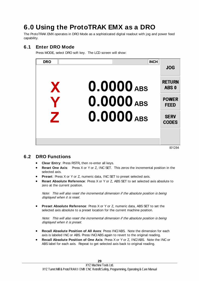
6.0 Using the ProtoTRAK EMX as a DRO The ProtoTRAK EMX operates in DRO Mode as a sophisticated digital readout with jog and power feed capability.
6.1 Enter DRO Mode Press MODE, select DRO soft key. The LCD screen will show:
6.2 DRO Functions Clear Entry: Press RSTR, then re-enter all keys. Reset One Axis: Press X or Y or Z, INC SET. This zeros the incremental position in the
selected axis. Preset: Press X or Y or Z, numeric data, INC SET to preset selected axis. Reset Absolute Reference: Press X or Y or Z, ABS SET to set selected axis absolute to
zero at the current position. Note: This will also reset the incremental dimension if the absolute position is being displayed when it is reset.
Preset Absolute Reference: Press X or Y or Z, numeric data, ABS SET to set the selected axis absolute to a preset location for the current machine position. Note: This will also reset the incremental dimension if the absolute position is being displayed when it is preset.
Recall Absolute Position of All Axes: Press INC/ABS. Note the dimension for each axis is labeled INC or ABS. Press INC/ABS again to revert to the original reading.
Recall Absolute Position of One Axis: Press X or Y or Z, INC/ABS. Note the INC or ABS label for each axis. Repeat to get selected axis back to original reading.
30 XYZ Machine Tools, Ltd.
XYZ Turret Mill & ProtoTRAK EMX CNC Retrofit Safety, Programming, Operating & Care Manual
6.3 Jog The servo motors can be used to jog the table.
1. Press the JOG soft key.
2. The feedrate box will read 2540 indicating the table will move in the X or Y positive direction at 2540 mmpm. A message will flash to warn you that JOG is activated.
3. Press +/- to reverse direction. The feedrate box will change to - 2540 Press +/- again to go back to JOG + (the + is not shown).
4. Press the down arrow key (to the right of the LCD screen) to reduce the jog speed in 10 percent increments. The feedrate and override boxes will show these adjustments. Press the up arrow key to increase the speed. The range is between 10% and 150%.
5. Press and hold X or Y to jog that axis. Release the key to stop.
6. To jog at a given rate, for example, 500 mmpm, simply press ‘500’ while the jog message is flashing. This number will appear in the feedrate box. When you press X or Y you will jog at this rate. Press the up or down arrow keys to adjust. In metric this number represents the percent of the maximum, or 2540 mmpm.
7. Press RETURN soft key to return to manual DRO operation.
6.4 Return to Absolute Zero At any time during manual DRO operation you may automatically move the table to your absolute zero location in X and Y by pressing the RETURN ABS 0 softkey. When you do, the conversation line will read "Ready to begin. Press Go when ready." Make sure your tool is clear and press the GO key. When you do, the servos will turn on, move the table at rapid speed to your X and Y absolute zero position, and then turn off. You will be at zero and in manual DRO operation.
6.5 Power Feed The servomotors can be used as a power feed for the table or saddle or both.
1. Press the POWER FEED soft key.
2. A message box will appear that shows the power feed dimensions. All power feedmoves are entered as incremental moves from the current position to the next position.
3. Enter a position by pressing the axis key, the distance to go and the +/- key (if needed). Input the entry by pressing INC SET. For example, if you wanted to make a power feed move of 50 mm of the table in the negative direction, you would enter: X, 50, +/-, INC SET.
4. Initiate the power feed move by pressing GO.
5. The feedrate is automatically set to 10 ipm (or 254 mmpm). Press the up or down arrow key to the right of the LCD screen to adjust the feedrate from 1 ipm to 100 ipm (or 254 to 2540 mmpm).
6. Press STOP to halt power feed. Press GO to resume.
7. Repeat the process beginning at "3" above as often as you wish.
6.6 Changing between Inch and mm Display. Use the Service codes to change the ProtoTRAK EMX from Imperial (Inch) to Metric (mm).
1. Enter the DRO Mode.
2. Press Serv Codes.
3. Enter 66, then Abs Set to go to mm dimensions.
4. Enter 67, then Abs Set to go to Inch dimensions.

31 XYZ Machine Tools Ltd.
XYZ Turret Mill & ProtoTRAK EMX CNC Retrofit Safety, Programming, Operating & Care Manual
6.7 Service Codes Service codes are accessed from the DRO screen. Please see Section 10 for a detailed explanation of Service Codes.
32 XYZ Machine Tools Ltd.
XYZ Turret Mill & ProtoTRAK EMX CNC Safety, Programming, Operating & Care Manual
7.0 Programming The ProtoTRAK EMX can be easily programmed for a wide variety of parts in two axes. A program is one or a series of events. It can either be a complete part, a set of operations on a side or only a small number of cuts. It is necessary to create a program when you want the EMX to machine the part for you.
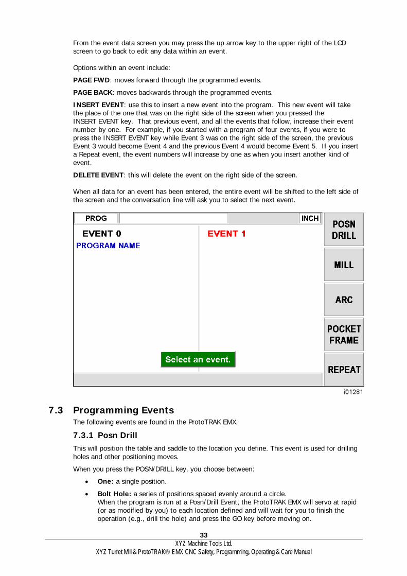
7.1 Enter Program Mode and Assign a Program Name To start programming, press MODE and select PROGRAM softkey. For a new program to be written, there cannot already be a program in the active or current program memory. When you first enter Program Mode, you will encounter a screen that allows you to enter a program name or to enter the program at different events. Event 0 is where you can enter the program name. You can also get to Event 0 by pressing Page Back from Event 1. The program name is highlighted and you may enter a new program name at this point. Program names are made up of up to eight numbers. Note: It is not necessary to enter a program name. If none is entered and the INC SET or ABS SET button is pushed, the system will assume the program name is 0. The ProtoTRAK EMX automatically holds all of the completed events as you program in current memory. Choices at the beginning of Program Mode:
GO TO BEGIN: puts Event 0 on the left side of the screen and the first event on the right side.
GO TO END: puts the last programmed event on the left side of the screen and the next event to be programmed on the right side.
GO TO #: enter the event number you wish to go to and then press SET. This puts the requested event number on the right side of the screen and the previous event number on the left.
Note: for a new program that has no Events, all the GO TO selections will take you to the beginning, with Event 0 on the left and the Select an Event options for Event 1 on the right.
7.2 Programming Strategy and Procedures The ProtoTRAK EMX makes programming easy by allowing you to program the actual part geometry as defined by the drawing. The basic strategy is to select the softkey event type (geometry) and then follow all instructions in the conversation line. When an event is selected, all the prompts will be shown on the right side of the information area. The first prompt will be highlighted and also shown in the conversation line. Input the dimension or data requested and press INC SET or ABS SET. For X or Y dimension data it is very important to properly select INC SET or ABS SET. For all other data either SET will do. As data are being entered, it will show in the conversation line. If you make a mistake, for example, you press the wrong number key, you can clear the input by pressing RESTORE. When SET, the data will be transferred to the information area, and the next prompt will be shown in the conversation line.
33 XYZ Machine Tools Ltd.
XYZ Turret Mill & ProtoTRAK EMX CNC Safety, Programming, Operating & Care Manual
From the event data screen you may press the up arrow key to the upper right of the LCD screen to go back to edit any data within an event. Options within an event include:
PAGE FWD: moves forward through the programmed events.
PAGE BACK: moves backwards through the programmed events.
INSERT EVENT: use this to insert a new event into the program. This new event will take the place of the one that was on the right side of the screen when you pressed the INSERT EVENT key. That previous event, and all the events that follow, increase their event number by one. For example, if you started with a program of four events, if you were to press the INSERT EVENT key while Event 3 was on the right side of the screen, the previous Event 3 would become Event 4 and the previous Event 4 would become Event 5. If you insert a Repeat event, the event numbers will increase by one as when you insert another kind of event.
DELETE EVENT: this will delete the event on the right side of the screen. When all data for an event has been entered, the entire event will be shifted to the left side of the screen and the conversation line will ask you to select the next event.
7.3 Programming Events The following events are found in the ProtoTRAK EMX.
7.3.1 Posn Drill This will position the table and saddle to the location you define. This event is used for drilling holes and other positioning moves.
When you press the POSN/DRILL key, you choose between:
One: a single position.
Bolt Hole: a series of positions spaced evenly around a circle. When the program is run at a Posn/Drill Event, the ProtoTRAK EMX will servo at rapid (or as modified by you) to each location defined and will wait for you to finish the operation (e.g., drill the hole) and press the GO key before moving on.
34 XYZ Machine Tools Ltd.
XYZ Turret Mill & ProtoTRAK EMX CNC Safety, Programming, Operating & Care Manual
7.3.2 Mill Event Use this to machine a straight line in any direction. The prompts you answer in this event will allow the ProtoTRAK EMX to calculate the complete tool path, including the starting position and tool offsets. It is not necessary to program a rapid move to the beginning position of the Mill Event.
When the program is run at a Mill Event, the ProtoTRAK EMX will rapid to the beginning position, prompt you to set the quill Z depth, move through the Mill Event at the speed you program and end at the ending position. (See the discussion on Continue below for the variation in tool motion if the event is connective).
7.3.3 Arc Event This is any part of a circle. Like the Mill Event, the prompts you answer will allow the ProtoTRAK EMX to calculate the complete tool path. When the program is run at an Arc Event, the ProtoTRAK EMX will rapid to the beginning position, prompt you to set the quill Z depth, move through the Arc Event at the speed you program and end at the ending position. (See the discussion on Continue below for the variation in tool motion if the event is connective).
7.3.4 Pocket/Frame Event Use this event to machine a pocket or profile (frame) with the minimum amount of programming. When you press the Pocket/Frame key, you choose between the following: Circle Pckt: a circle and all the material in the centre. Includes a finish cut. Rect Pckt: a rectangle and all the material in the middle. Includes a finish cut. Circle Profile: a circular circumference. Includes a finish cut. Rect Profile: a square or rectangular perimeter. Includes a finish cut.
When the program is run at a Profile Event, the ProtoTRAK EMX will rapid from wherever it is to 3 o’clock on circular frames and X1, Y1 on rectangular frames. After you set the cutter and press go, it will move through the first pass and then the finish cut at the programmed feedrate and then move the cutter away from the part by the amount of the programmed finish cut. The Pocket Event will rapid to the centre of the circle or rectangle. After you set the cutter and press GO, it will move in a logical path through the material (leaving the finish cut, if one is programmed), using 70% of the cutter diameter. After the centre is cleared, it will do the finish cut and ramp away from the part at the end by the amount of the programmed finish cut.
7.3.5 Repeat Events This allows you to repeat an event or a group of events up to 99 times, with an offset in X or Y. This can be useful for drilling a series of evenly spaced holes, duplicating some machined shapes or even repeating an entire program with an offset for a second fixture. Another use is to repeat a programmed set of drill events (without offsets) so you can center drill, drill, and counterbore without reprogramming the second and third operations. Repeat events may be "nested" up to five deep. That is, you can repeat a Repeat Event, of a Repeat Event, of a Repeat Event of some programmed event(s). One new tool number may be assigned for each Repeat Event.

35 XYZ Machine Tools Ltd.
XYZ Turret Mill & ProtoTRAK EMX CNC Safety, Programming, Operating & Care Manual
7.4 Prompts Used to Define the Events The following prompts are encountered in programming the events.
# Holes - the number of holes in the bolt hole pattern. Angle - the location of the first hole to be machined in a Bolt Hole event. It is the angle from the positive X axis (that is, 3 o'clock) to the hole. The positive angle is measured counterclockwise from 0.000 to 359.999 degrees. Conrad - There are two meanings to Conrad: 1. The connecting radius between line or arc being programmed and the next line or arc
event. Simply enter the radius value at this prompt and the ProtoTRAK EMX will figure the tool path to go from one event to the next with a connecting radius. If no radius is desired, or if you are programming the last event, enter 0 by pressing the INC SET or ABS SET key without a number value.
2. The corner radius in a rectangular pocket or frame. The radius is tangential.
Continue - to tell the ProtoTRAK EMX if the event is continuous to the next event(s) to be programmed. This saves inputs needed to define a profile. If the event is programmed with a Yes, for continue, then X begin, Y begin, Tool Offset, Feedrate and Tool # will not be prompted in the next one. Direction - for an arc or circle, the direction is clockwise or counterclockwise. Feedrate - the milling feedrate in in/min from .1 to 99.9 or in mmpm from 5 to 2500. Fin cut - for a pocket or frame, the width of the finish cut. If 0 is input, there will be no finish cut. Radius - the radius of the bolt hole pattern, arc or circle. Tool # - the number you assign to identify the tool. Tool Diameter - the diameter of the tool. See the note on finish cuts later in this section. Tool offset - the selection of the tool offset, right, left or center relative to the programmed edge and tool movement. X or Y - the X or Y dimension, may be defined in absolute or incremental reference. X Begin or Y Begin - the X or Y beginning point of the line or arc. X Center or Y Center - the X or Y dimension of the center of the bolt hole pattern, arc or circle. X End or Y End - the X or Y ending point of the line or arc. X1, Y1, and X3, Y3 - the X and Y dimensions for the opposite corners on a rectangular pocket or frame.
Prompts unique to the Repeat event: First Event # - the first event to be repeated. Last Event # - the last event to be repeated. If only one event is to be repeated, the First and Last events will be the same number. X Offset - the incremental X offset from the event to be repeated.
36 XYZ Machine Tools Ltd.
XYZ Turret Mill & ProtoTRAK EMX CNC Safety, Programming, Operating & Care Manual
Y Offset - the incremental Y offset from the event to be repeated. # Repeats - the number of times the events are to be repeated up to 99.
7.5 Continue In MILL and ARC events the ProtoTRAK EMX will ask you to choose YES or NO to the continue prompt. If you want the cutter to keep machining from the event you are programming to the next event without stopping, you should choose YES. If you want the cutter X/Y motion to stop so that you can adjust Z quill position, then choose NO. If you choose YES, then the next event must be a connective event. Prompts for the X Beginning location, Y Beginning location, Tool Offset, Feedrate, and Tool # will not be asked because, if the events are connective, this data are already known. The programmed feedrate may be different for different events, even when the events are connective. To change the feedrate within a group of connective events, finish programming the event and then use the up arrow key to get access to the feedrate prompt in previous events.
7.6 Assumed Tool Offset, Feedrate, and Tool # When the INC SET key is pressed, the ProtoTRAK EMX will automatically program the following for these prompts: TOOL OFFSET: for a Mill or Arc Event, same as the last event if that event was a Mill or Arc Event, otherwise, Tool Centre. FEEDRATE: same as last event if that event was a Mill, Arc, Pocket, or Frame. TOOL #: same as last event, or Tool 1 in the first event. You may change these assumed inputs by simply inputting the correct data when the event is programmed.
7.7 Incremental Reference Position When X and Y data for the beginning position of any event are input as incremental data, this increment must be measured from some known point in the previous event. Following are the positions for each event type from which the incremental moves are made in the subsequent event: POSITION/DRILL: X and Y programmed BOLT HOLE: X CENTER and Y CENTER programmed MILL: X END and Y END programmed ARC: X END and Y END programmed CIRCLE POCKET or FRAME: X CENTER and Y CENTER programmed RECTANGLE POCKET or FRAME: X1 and Y1 corner programmed position REPEAT: The appropriate reference position for the event prior to the first event that was repeated.

37 XYZ Machine Tools Ltd.
XYZ Turret Mill & ProtoTRAK EMX CNC Safety, Programming, Operating & Care Manual
7.8 Finish Cuts The Pocket and Frame events are designed with built-in finish cut routines because they are complete, stand-alone pieces of geometry. Shapes machined with a series of Mill or Arc events don't have an automatic routine for making finish cuts. Instead, it is very easy to get a finish pass by overstating the size of the tool for the events in the initial pass, and then using a Repeat Event and programming a new tool with the actual size of the tool. For the first pass, the cutter will be positioned away from the final cut half the amount of the difference between the actual size of the cutter and the diameter you put in. When the Repeat Events are run, the same cutter will be positioned correctly to do the final pass to size.
7.9 Look You can look at part graphics while in the Program Mode. At any time an event is finished programming and the Select Event prompt appears in the conversation line, simply press the LOOK hard key. The programmed events are automatically sized so that everything fits on the screen. To return to the programming, press the RETURN softkey. The part graphics are useful for checking what you have programmed so far. Certain kinds of programming mistakes are not caught by the graphics. These will surface when running the program.
7.10 A Sample Program This simple part will be used to illustrate the process of programming.
Steps
1. Decide the order of machining. This part can be held in a vice. First we will drill the two holes and then we will mill the slot.
2. Decide the Absolute reference. In this case we will use the lower left corner as our 0 location for X and Y.

38 XYZ Machine Tools Ltd.
XYZ Turret Mill & ProtoTRAK EMX CNC Safety, Programming, Operating & Care Manual
3. Enter the Program Mode. If there is already a program in the current memory, go into the Program In/Out Mode and press the CLEAR CURRENT softkey. (You may want to store the program in current memory first.).
4. Assign a part number. When there is no program in the current memory, the system will prompt for a program part number as soon as it goes into Program Mode. Enter a numeric part number (or not, if you don't want one) and press SET.
5. Program the first hole.
Event 1
Prompt You press these keys SELECT EVENT POSN/DRILL SELECT ONE X 19.05 ABS SET Y 50.00 ABS SET Tool # 1 INC or ABS SET Tool Dia 6 INC or ABS SET
Note: For the non-referenced data, either SET key will do. This first tool is a center drill. For the Position/Drill Event, the program will run
without a tool diameter, but one may be entered as a reminder.
6. Program the second hole.
Event 2
Prompt You press these keys SELECT EVENT POSN/DRILL SELECT ONE X 25.00 INC SET Y INC SET Tool # INC SET Tool Dia INC SET
Note: For the dimensions, it was handy to read these right off the drawing and put them
in as incremental moves from the previous hole. We could have also programmed using X = 44.05 Abs Set and Y = 50.0 Abs Set.
The Inc Set entry for Y was taken as a 0 incremental move, you do not have to press 0.
The Inc Set for the Tool # and Tool Diameter were taken as "use the data from the previous event."
7. Repeat the holes to drill to size.
Event 3
Prompt You press these keys SELECT EVENT REPEAT First Event # 1 INC or ABS SET Last event # 2 INC or ABS SET X offset INC SET Y offset INC SET No. of Repeats 1 INC or ABS SET Tool # 2 INC or ABS SET Tool Dia 6.00 INC or ABS SET
Note: We want to visit the same two holes, in the same place, with a different tool to do the final drilling.

39 XYZ Machine Tools Ltd.
XYZ Turret Mill & ProtoTRAK EMX CNC Safety, Programming, Operating & Care Manual
8. Look at what you have programmed. Press the LOOK key. You will see two + marks on opposite sides of the screen to show where the holes have been programmed. Press RETURN to get back to the programming.
9. Program the slot.
Event 4
Prompt You press these keys SELECT EVENT MILL X Begin 107.55 ABS SET or 63.50 INC SETY Begin 20.32 ABS SET X End INC SET Y End 33.00, INC SET Conrad INC SET Tool Offset 0, INC or ABS SET Feedrate 200, INC or ABS SET Continue 2, INC or ABS SET Tool # 3, INC or ABS SET Tool Dia 10, INC or ABS SET
10. Look at the program again. If all went well, you should now see the two holes and slot
tool path in the same proportion as they appear on the drawing. If not, check your inputs and try again.
When you machine the part, you will probably want to use a drill to open up a hole at the beginning of the slot for your milling tool. To do that, you can either:
program a position event for the drill, or when the ProtoTRAK EMX positions at the beginning of the slot, centre drill and drill
first, then put in your milling tool.
If you have a lot of parts to do, it is worth your while to add the drill into the program, but probably not if you only have one or two. The great thing about the ProtoTRAK EMX is you don't have to make it part of the program. It still does the positioning for you and you have the flexibility to do the drill operations before you press the GO button for the milling.
40 XYZ Machine Tools Ltd.
XYZ Turret Mill & ProtoTRAK EMX CNC Safety, Programming, Operating & Care Manual
8.0 Changing or Correcting Programs In the Program Mode, you can easily correct mistakes or make changes to the program.
8.1 Deleting a Partially Programmed Event If you wish not to program an event (or start over) after you have started to program, press the DELETE EVENT softkey and the screen will revert to the "Select Event" prompt.
8.2 Editing Data while Programming an Event All data are entered by pressing the appropriate numeric keys and pressing INC SET or ABS SET. If you enter an incorrect number before you press INC SET or ABS SET you may clear the number by pressing RESTORE. Then, input the correct number and press SET. If incorrect data have been entered and SET, you may correct it as you are still programming that same event by pressing the arrow up or arrow down keys to the right of the LCD screen until the incorrect data are highlighted and shown in the conversation line. Enter the correct number and SET. The ProtoTRAK EMX will not allow you to skip past prompts (by pressing an arrow key) that need to be entered to complete an event.
8.3 Editing Previously Programmed Events From the Select Event screen you may press the arrow up key to the right of the LCD screen and the program will move back one event. From that point, you will have the following softkey options: INSERT EVENT allows you to insert a new event between the two shown on the left and right side of the screen. When you press INSERT EVENT the screen will revert to the Select Event screen and you may program the new added event as you would any other. Subsequent events will be renumbered accordingly. DELETE EVENT allows you to delete the event on the right side of the screen. Subsequent events will be renumbered accordingly. PAGE FWD (Forward) indexes the event forward by one. PAGE BACK indexes the event back by one.
8.4 Changing the Feedrate If the feedrate is edited in any event it will automatically be edited in every subsequent and contiguous event with the same tool number and feedrate. For example, let’s say events 5 through 10, and 13 through 16 were all programmed with tool number 2, and 125 mmpm feedrate. If you edit the feedrate in Event 7 to 75 mmpm, it will automatically change Events 8, 9, and 10 also. Events 5, 6, 13, 14, 15, and 16 will not be affected
8.5 Changing a Part Number (making a copy of a program) You may want to rename a part program, or make a copy of a program using a different name. The latter may be useful if you have a new part to do that is similar to a part that you already have programmed. Make a copy of the program by saving it under a new part number and then make the changes. You can rename a part program in three ways:
Press the PAGE BACK key past the first event until you are at Event 0 and the prompt for Program Part Number. Enter the new part number and press SET.
Exit the Program Mode by pressing Mode and then re-enter it. You will have an opportunity to rename it then.

41 XYZ Machine Tools Ltd.
XYZ Turret Mill & ProtoTRAK EMX CNC Safety, Programming, Operating & Care Manual
Rename it in the Program In/Out Mode. After pressing the PROG IN/OUT key, simply enter the new part number and press SAVE.
If the previous part program is already stored on the system internal storage it will remain in storage under the previous part number with the same information it had the last time it was stored.
8.6 Saving Changes to a Program
If a program is opened from storage and changes are made, the program must be stored again in Prog In/Out Mode for the changes to be preserved in the stored copy. Programs in current memory may be changed and run with the changes, but unless they are saved again, the changes made will be lost when the program is cleared from current memory. If you intend to keep the changes made to your program it is a good practice to store the program occasionally in case a power loss causes the program to be ejected from current memory.
8.7 Erasing an Entire Program To erase an entire program from current memory, go to the Program In/Out Mode and press ERASE PROG. You will be prompted "Are you sure you want to erase this program?" You may want to store the program before you clear it from current memory. If it is not stored, pressing YES will permanently erase the program. To erase an entire program from the internal storage, input the part number and then press DELETE. Programs in current memory will not be affected by this operation. You could erase a part number on the internal storage and the program in current memory will remain in current memory, even if it has the same part number as the one just erased. Programs in current memory will automatically be erased when another program is retrieved from storage.

42 XYZ Machine Tools Ltd.
XYZ Turret Mill & ProtoTRAK EMX CNC Safety, Programming, Operating & Care Manual
9.0 Making Parts with the CNC 9.1 Setting Up
Before you can run your program, you must set your absolute position in the DRO Mode. The CNC will use this absolute position as a reference for running your program.
9.2 Starting After setting up in the DRO Mode, go into the Run Mode. You will see this screen:
The part number appears in the status line. To start the program, select between START and START EVENT#.
START – starts running the program from the beginning. START EVENT # – starts running the program from an event in the middle. If you
press this key you will be prompted to enter the event number for where to start.
9.3 Display Messages in Program Run IN POSITION: appears in the status line when the program has come to a pause. EVENT # and type: this is the current or next event to be run. REPEAT: the number of the repeat for repeat events. FEEDRATE: the actual table feedrate. OVERRIDE: the feedrate override, controlled by pressing the up or down arrow keys above and below the soft keys.
9.4 Program Run Prompts During Program Run, messages that direct you will appear in a green box. The ProtoTRAK EMX will wait until you press Go before moving the servo motors. What you need to do is obvious in most cases. Below is some supplemental information.
Check Z: Means to make sure the quill is properly retracted because the next move will be rapid. Press GO to continue.

43 XYZ Machine Tools Ltd.
XYZ Turret Mill & ProtoTRAK EMX CNC Safety, Programming, Operating & Care Manual
Set Z: Means to drill and retract the quill for a drilling operation, or set and lock the quill to the proper depth for a milling cut. Press GO to continue.
Run Over: Means that the program run is complete. If you are running a second part that will be fixtured/clamped in the exact same position as the first part, you do not need to relocate the absolute 0 and restart. Instead, press the NEXT PART softkey when the conversation line states "Run Over" and the system will proceed directly to Event 1.
9.5 Stop At any time, pressing the STOP key will halt the program. This freezes the program at that point. To continue, press the GO key.
9.6 Feedrate Override The run feedrate may be changed at any time by pressing the up and down arrow keys to the right of the LCD screen. Each press changes the programmed feedrate (as well as the rapid feedrate) in 10% increments. The maximum overrides are from 10% to 150% of programmed feedrates.
9.7 Trial Run Before cutting material, it is recommended that you do a trial run by keeping the quill up while the program runs through. Verify that the absolute reference is set correctly.
9.8 Data Errors A program must make sense geometrically. For example, you can't machine a 6 mm diameter circular pocket using a 12 mm end mill. Data errors will nearly always be detected when the ProtoTRAK EMX runs through a program--either as a trial run or on an actual part run.
The Error message displays the error number (not necessarily important to you) and the event where the error was detected. This is not necessarily the event that is in error since the system often "looks ahead" to make sure there is compatibility from one event to another. In addition, an explanation is given for each data error type as well as a suggested solution.
9.9 Fault Messages The ProtoTRAK performs a number of automatic checks or self-diagnostics. If problems are found it will signal you through the display.

44 XYZ Machine Tools Ltd.
XYZ Turret Mill & ProtoTRAK EMX CNC Safety, Programming, Operating & Care Manual
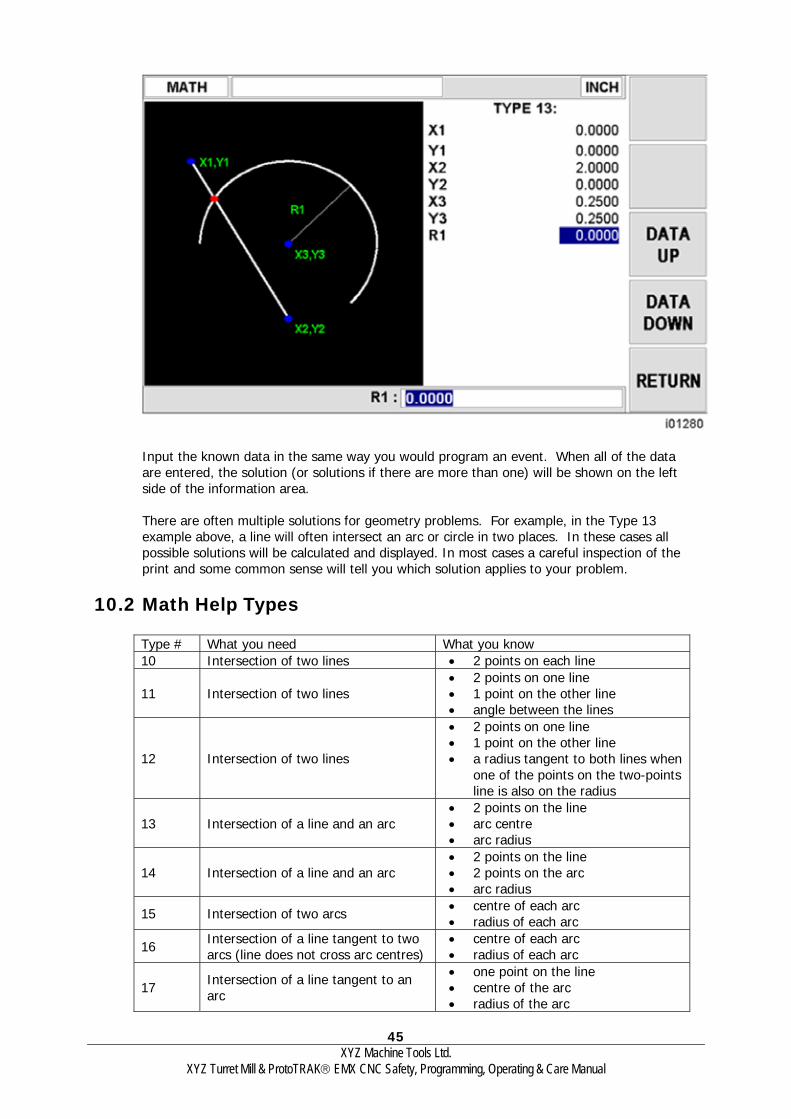
10.0 Math Help Drawings are, unfortunately, not always drawn and labeled in such a way as to provide all of the points necessary for programming. To minimize this problem, the ProtoTRAK EMX provides a graphic math help function which can be used to automatically calculate points of intersection, centres of arcs, trig functions, square roots, etc.
10.1 Procedure To enter the Math Help Mode, press MODE and select the MATH HELP soft key. The screen will show:
If you already know the math help type you want (see Section 10.2) press the TYPE # softkey and enter the number and SET.
If you do not know the type, select from A through E using the softkeys.
If, for example, you wish to find the intersection of a straight line and an arc or circle, press the B softkey. The screen will show three choices for finding the intersection of a line with different information given.
If the information you know about the line and arc correspond to Type 13, then select the 13 softkey. The screen will then show:
45 XYZ Machine Tools Ltd.
XYZ Turret Mill & ProtoTRAK EMX CNC Safety, Programming, Operating & Care Manual
Input the known data in the same way you would program an event. When all of the data are entered, the solution (or solutions if there are more than one) will be shown on the left side of the information area. There are often multiple solutions for geometry problems. For example, in the Type 13 example above, a line will often intersect an arc or circle in two places. In these cases all possible solutions will be calculated and displayed. In most cases a careful inspection of the print and some common sense will tell you which solution applies to your problem.
10.2 Math Help Types
Type # What you need What you know 10 Intersection of two lines 2 points on each line
11 Intersection of two lines 2 points on one line 1 point on the other line angle between the lines
12 Intersection of two lines
2 points on one line 1 point on the other line a radius tangent to both lines when
one of the points on the two-points line is also on the radius
13 Intersection of a line and an arc 2 points on the line arc centre arc radius
14 Intersection of a line and an arc 2 points on the line 2 points on the arc arc radius
15 Intersection of two arcs centre of each arc radius of each arc
16 Intersection of a line tangent to two arcs (line does not cross arc centres)
centre of each arc radius of each arc
17 Intersection of a line tangent to an arc
one point on the line centre of the arc radius of the arc
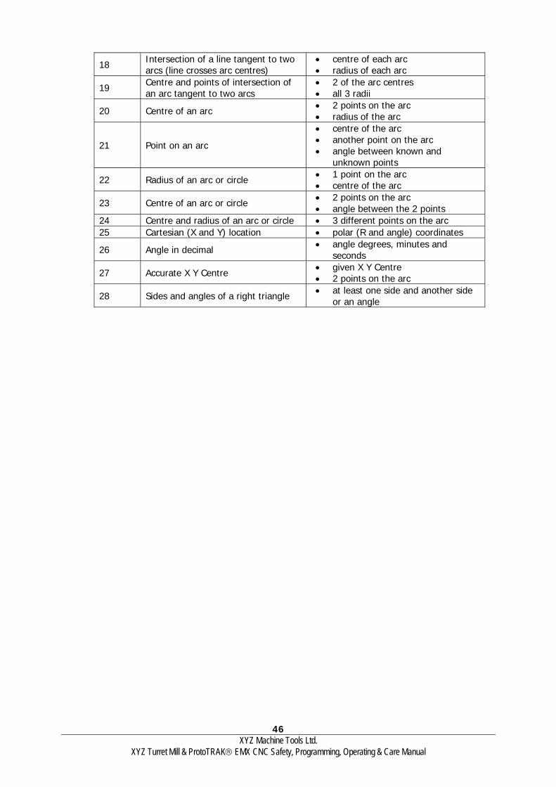
46 XYZ Machine Tools Ltd.
XYZ Turret Mill & ProtoTRAK EMX CNC Safety, Programming, Operating & Care Manual
18 Intersection of a line tangent to two arcs (line crosses arc centres)
centre of each arc radius of each arc
19 Centre and points of intersection of an arc tangent to two arcs
2 of the arc centres all 3 radii
20 Centre of an arc 2 points on the arc radius of the arc
21 Point on an arc
centre of the arc another point on the arc angle between known and
unknown points
22 Radius of an arc or circle 1 point on the arc centre of the arc
23 Centre of an arc or circle 2 points on the arc angle between the 2 points
24 Centre and radius of an arc or circle 3 different points on the arc 25 Cartesian (X and Y) location polar (R and angle) coordinates
26 Angle in decimal angle degrees, minutes and seconds
27 Accurate X Y Centre given X Y Centre 2 points on the arc
28 Sides and angles of a right triangle at least one side and another side or an angle

47 XYZ Machine Tools Ltd.
XYZ Turret Mill & ProtoTRAK EMX Safety, Programming, Operating & Care Manual
11.0 Program Memory & Storage The ProtoTRAK EMX can only have one program at a time in current memory. This is the program you see when you enter the program mode and is the one that is available to run. Programs may be stored for future use on the ProtoTRAK EMX internal storage. Part programs are saved to storage or opened from storage in the Program In/Out Mode. When programs are transferred back and forth from current memory and storage, they stay in both locations unless erased or cleared. In other words, opening a program from internal storage into the current memory does not remove it from the internal storage. Only deleting the program will remove it.
11.1 Cautions on Opening and Deleting Programs Care must be taken to keep from losing a program you wish to keep. This can happen two ways. First, whenever a program is opened, it is loaded into the ProtoTRAK EMX's computer program memory. When this happens, your existing current program is erased. Therefore, if your current program is one you want to keep, be certain to store it before you retrieve another program. Second, to store a program it must have a part number so that the ProtoTRAK EMX can find it when you want to open it. However, no two programs can have the same part number (how would the system decide which to retrieve?). Therefore, if you store a program with any particular part number, it will automatically erase any other program with that same part number. In both cases above the ProtoTRAK EMX will give you a warning before erasing or overwriting your program.
11.2 Program Formats and Labeling The ProtoTRAK family of products has its own unique programming system; one that organises the program into events rather than codes and blocks. Programs written on a two-axis milling control (such as the ProtoTRAK EMX) will have the extension .MX2. The .MX2 programs created by the ProtoTRAK EMX are compatible with those created on other ProtoTRAK two-axis CNCs, provided that the event types of the program are found in the control that is running the program.

48 XYZ Machine Tools Ltd.
XYZ Turret Mill & ProtoTRAK EMX Safety, Programming, Operating & Care Manual
11.3 Saving and Opening Programs from the ProtoTRAK EMX internal storage
Press MODE, and select the PROGRAM IN/OUT softkey. The display will show:
A view of Program In/Out Mode with a few programs saved. All part numbers in the ProtoTRAK EMX internal storage are listed in the Information Area.
The part number of the current program (in current memory) is shown in the
conversation line. You may change the part number at this screen by entering a new number and pressing SAVE.
OPEN will write a .MX2 program from the internal storage to current memory. First input the part number and then press the OPEN key.
SAVE will write the program in current memory to the internal storage. You will see the program added to the list in the information area after it is stored.
DELETE will erase a program from the internal storage. First input the program number and then press the DELETE key.
CLEAR CURRENT will erase the program from current memory. You do this to clear current memory in order to write a new program.
The PAGE FWD (Forward) softkey will continue the part number list if there are too many to be shown on the screen.
11.4 File Transfer and Backup USB ports are provided and a USB Thumb drive offered as a convenient way to transfer and backup part programs.

49 XYZ Machine Tools Ltd.
XYZ Turret Mill & ProtoTRAK EMX Safety, Programming, Operating & Care Manual
Please note:
Refer to page 16 for the list of thumb drives we have verified will work. Before you can transfer programs from the thumb drive to the ProtoTRAK EMX, you
must put the files in a folder named “Programs”. To move files from the ProtoTRAK EMX internal storage to a thumb drive, do the following:
1. Plug the Thumb Drive into the ProtoTRAK EMX USB port. 2. Go to the DRO Mode. 3. Press Serv Codes. 4. Under group A, Software Service Codes, select code 340 “Copy MX2 Files from Control
to USB Drive. 5. The ProtoTRAK EMX will place a folder on the thumb drive named “Programs” (if one
doesn’t exist already) and write the programs saved in the internal storage of the ProtoTRAK EMX to the USB Thumb Drive. The programs will now be saved in both places.
To move files from a thumb drive to the ProtoTRAK EMX internal storage, do the following:
1. Plug the Thumb Drive into the ProtoTRAK EMX USB port. 2. Go to the DRO Mode. 3. Press Serv Codes. 4. Under group A, Software Service Codes, select code 341 “Copy MX2 Files from USB
Drive to Control. 5. All the programs saved in the folder “Programs” on the thumb drive will also be saved
on the ProtoTRAK EMX internal storage. If there are programs with the same name in the destination location you will be asked by the ProtoTRAK EMX if you want to overwrite the existing file. Programs of different names on the destination location will not be affected. In keeping with our philosophy to make the ProtoTRAK EMX as simple as possible, we have elected the simplest possible program storage routines. File transfers between the ProtoTRAK EMX and thumb drive will move all programs between the two. This eliminates the complexity of adding file management to the ProtoTRAK EMX system. Files may be managed on the thumb drive with your offline computer.

50 XYZ Machine Tools Ltd.
XYZ Turret Mill & ProtoTRAK EMX Safety, Programming, Operating & Care Manual
12.0 Service Codes Service codes are special codes used for set-up, installation or program file transfer.
12.1 Service Code Procedure 1. Go to the DRO Mode. 2. Press SERVICE CODES. 3. Input one of the codes from the list in section 12.2. 4. Press SET.
For some of the codes, there are additional instructions.
12.2 Service Code Types Code Description Notes 12 Determine feed forward
constant Runs a routine that determines the system friction for setting feed forward constant. Caution! Do not use this code unless you understand the consequences. Run this service code whenever the friction characteristics of your machine have changed.
13 Reset the default feed forward constant
In case you ignored the warning above, this resets the default set at the factory.
15 Activate or Deactivate Z readout
The Z-axis readout should be activated if you installed the optional Z-axis scale. This may be added to your system at any time and the Z readout activated by this code.
22 Turn on simulation For demo purposes, the ProtoTRAK EMX may be run in simulation mode where the control operates normally but does not send commands to the motors. If you use this code, don't forget to restore your CNC to normal operation with Service Code 89! Simulation mode is also cancelled by turning the control on and off.
33 Software ID Displays the version of software your ProtoTRAK EMX is using. 54 Continuous run mode Keeps running the system through the program without
stopping. It is used for testing. 66 Metric mode To have the ProtoTRAK EMX power up in Metric measurement. 67 Inch mode To have the ProtoTRAK EMX power up in Inch measurement. 79 Turn on beeper Factory setting. 80 Turn off beeper 81 Keyboard test For testing the front panel buttons. 89 Cancel simulation Cancel the Service Code 22 simulation. 97 Axis configuration To orient the motor encoder. This should not need to be done
except in a service situation. 100 Axis open loop test Runs selected axis at rapid for one second and displays values.
Caution! The machine will move. Be sure you understand the consequences before you use this code.
122 Calibration offset Use this to modify your calibration factor. Cut part, measure, follow the instructions on the screen .
123 Calibration of each axis of measurement.
Detailed instructions are found in SWI Publication No. 26055 "ProtoTRAK EMX Installation and Service Manual."
125 Display calibration factors
Used to display machine configuration values such as calibration and backlash.
127 Single encoder backlash calibration
Used to calculate a backlash value for entering in Code 128.
128 Enter backlash value Used to enter the backlash value calculated using Code 127. 141 Load parameters Will take parameters from USB thumb drive 142 Save control parameters Save parameters to the USB thumb drive.

51 XYZ Machine Tools Ltd.
XYZ Turret Mill & ProtoTRAK EMX Safety, Programming, Operating & Care Manual
Code Description Notes 316 Update software Used to update to the latest software version from the USB
thumb drive. 340 Back up programs Copy all the programs on the internal storage to the USB
thumb drive. 341 Load programs Copy all the programs on the USB thumb drive to the internal
storage.
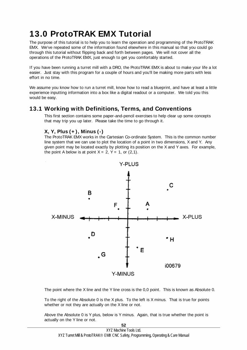
52 XYZ Machine Tools Ltd.
XYZ Turret Mill & ProtoTRAK EMX CNC Safety, Programming, Operating & Care Manual
13.0 ProtoTRAK EMX Tutorial The purpose of this tutorial is to help you to learn the operation and programming of the ProtoTRAK EMX. We’ve repeated some of the information found elsewhere in this manual so that you could go through this tutorial without flipping back and forth between pages. We will not cover all the operations of the ProtoTRAK EMX, just enough to get you comfortably started. If you have been running a turret mill with a DRO, the ProtoTRAK EMX is about to make your life a lot easier. Just stay with this program for a couple of hours and you'll be making more parts with less effort in no time. We assume you know how to run a turret mill, know how to read a blueprint, and have at least a little experience inputting information into a box like a digital readout or a computer. We told you this would be easy.
13.1 Working with Definitions, Terms, and Conventions This first section contains some paper-and-pencil exercises to help clear up some concepts that may trip you up later. Please take the time to go through it. X, Y, Plus (+), Minus (-) The ProtoTRAK EMX works in the Cartesian Co-ordinate System. This is the common number line system that we can use to plot the location of a point in two dimensions, X and Y. Any given point may be located exactly by plotting its position on the X and Y axes. For example, the point A below is at point X = 2, Y = 1, or (2,1).
The point where the X line and the Y line cross is the 0,0 point. This is known as Absolute 0.
To the right of the Absolute 0 is the X plus. To the left is X minus. That is true for points whether or not they are actually on the X line or not.
Above the Absolute 0 is Y plus, below is Y minus. Again, that is true whether the point is actually on the Y line or not.
53 XYZ Machine Tools Ltd.
XYZ Turret Mill & ProtoTRAK EMX CNC Safety, Programming, Operating & Care Manual
Quiz 1
Answer these questions about what you've just read. Check your answers at the end of this section.
1. Absolute 0 is the point where _________________________________.
2. Left of the Absolute 0 point is (X or Y) minus.
3. Above the Absolute 0 point is (X or Y) plus.
4. True or false. Any point in two dimensions can be plotted with the Cartesian Coordinate System.
Tip: if you have any problem with this part, take this manual out to your machine and put the drawing under the spindle so that the 0, 0 point is lined up with the centre of the spindle. Zero out the DRO on your display and crank the table different directions. Watch the DRO measurement count up and down, turning from positive to negative as you pass the 0, 0 points.
Quiz 2
Write down the X and Y dimensions (including the + or - sign) of points A through H in the figure above:
X Y A B C D E F G H
Check your answers at the back of this section.
Absolute (ABS) and Incremental (INC) In the previous section we saw that the absolute dimension is the point at which both X and Y are 0. Every part we make with a ProtoTRAK EMX will have an absolute zero that you give it. We want to put the Absolute 0 where it will make it easy to define the other points we need to machine, so a corner or the centre of a circular pattern are usually the best. When we program, we need to tell the ProtoTRAK EMX what the reference point is for the numbers we put in. When your reference point is the 0,0 we call that an Absolute Reference. That means that the number you put in is measured from 0,0. There is another way to define a point and that is with Incremental dimensions. Incremental dimensions are simply dimensions measured from the previous point. Consider the example below. If we say the bottom left corner is absolute zero (ABS 0) then the dimensions are absolute or incremental as shown.

54 XYZ Machine Tools Ltd.
XYZ Turret Mill & ProtoTRAK EMX CNC Safety, Programming, Operating & Care Manual
Quiz 3
What are the absolute co-ordinates of the points A to M in the figure below; given that Absolute Zero is at Point A?
What are the incremental dimensions?
X Y From D to E From E to F From D to F From L to B From G to M From H to M From M to H From K to K
Check your answers at the back of this section.
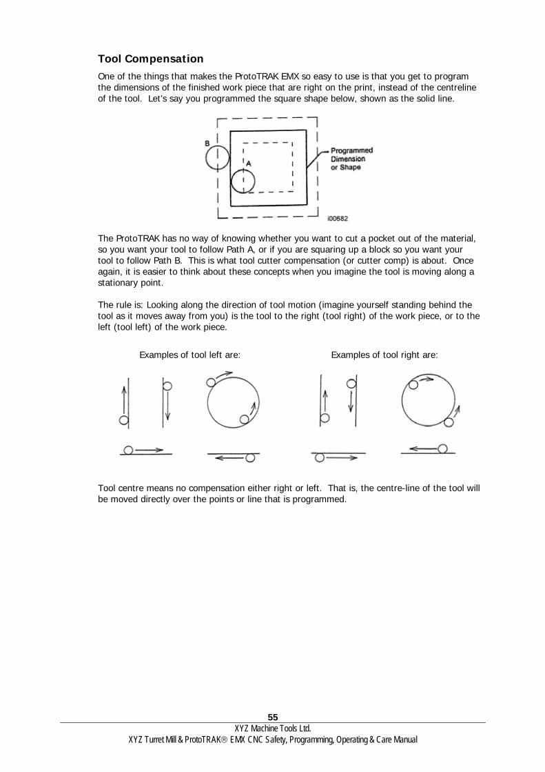
55 XYZ Machine Tools Ltd.
XYZ Turret Mill & ProtoTRAK EMX CNC Safety, Programming, Operating & Care Manual
Tool Compensation One of the things that makes the ProtoTRAK EMX so easy to use is that you get to program the dimensions of the finished work piece that are right on the print, instead of the centreline of the tool. Let’s say you programmed the square shape below, shown as the solid line.
The ProtoTRAK has no way of knowing whether you want to cut a pocket out of the material, so you want your tool to follow Path A, or if you are squaring up a block so you want your tool to follow Path B. This is what tool cutter compensation (or cutter comp) is about. Once again, it is easier to think about these concepts when you imagine the tool is moving along a stationary point. The rule is: Looking along the direction of tool motion (imagine yourself standing behind the tool as it moves away from you) is the tool to the right (tool right) of the work piece, or to the left (tool left) of the work piece.
Examples of tool left are: Examples of tool right are:
Tool centre means no compensation either right or left. That is, the centre-line of the tool will be moved directly over the points or line that is programmed.

56 XYZ Machine Tools Ltd.
XYZ Turret Mill & ProtoTRAK EMX CNC Safety, Programming, Operating & Care Manual
Quiz 4 For the part, tool, and direction shown, indicate whether the compensation is Right, Left, or Centre. Check your answers at the back of this manual.
Conrad (Connecting or Corner Radius)
Conrad is another really nice feature of the ProtoTRAK EMX. In the example below you could machine a straight line from Point A to B, then an ARC with radius R from B to D, then another straight line from D to E.
The problem is that the arc is not easy to program because you often don’t know where point D or B, or the centre of R is located. However, you may know where Point C is, or you may be able to figure it out easily. In that case you can program the above part by programming a straight line from A to C, tell the control when it asks that you have a CONRAD equal to R, and then program another straight line from C to E. The ProtoTRAK will automatically blend the connecting radius (CONRAD R) between the two straight lines with no additional input.
For Rectangular Pockets or Frames, CONRAD stands for corner radius. You may input any value that makes sense considering the size of the pocket and the diameter of the tool.

57 XYZ Machine Tools Ltd.
XYZ Turret Mill & ProtoTRAK EMX CNC Safety, Programming, Operating & Care Manual
Quiz Answers Quiz 1
1. Absolute 0 is the point where the X and Y lines cross.
2. Left of the Absolute 0 point is X minus.
3. Above the Absolute 0 point is Y plus.
4. True. Any point in two dimensions CAN be plotted with the Cartesian Coordinate System.
Quiz 2
X Y A 2 1 B -4 2 C 4 3 D -4 -2 E 1 -3 F -1 1 G -3 -4 H 4 -2
Quiz 3
X Y
From D to E 37.50 inc 0 inc From E to F 37.50 0 From D to F 75.00 0 From L to B 0 -100.00 From G to M 50.00 0 From H to M 50.00 -37.50 From M to H -50.00 37.50 From K to K 0 0
Quiz 4
A Right B Left C Left D Right E Left F Left G Right H Right I Left
X Y A 0 abs 0 abs B 0 -50.00 C 150.00 -50.00 D 62.50 25.00 E 100.00 25.00 F 137.50 25.00 G 75.00 -37.50 H 75.00 0 J -50.00 0 K 150.00 50.00 L 0 50.00 M 125.00 -37.50
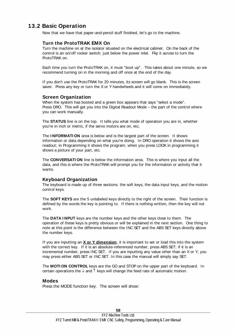
58 XYZ Machine Tools Ltd.
XYZ Turret Mill & ProtoTRAK EMX CNC Safety, Programming, Operating & Care Manual
13.2 Basic Operation Now that we have that paper-and-pencil stuff finished, let’s go to the machine. Turn the ProtoTRAK EMX On Turn the machine on at the isolator situated on the electrical cabinet. On the back of the control is an on/off rocker switch; just below the power inlet. Flip it across to turn the ProtoTRAK on. Each time you turn the ProtoTRAK on, it must “boot up”. This takes about one minute, so we recommend turning on in the morning and off once at the end of the day. If you don’t use the ProtoTRAK for 20 minutes, its screen will go blank. This is the screen saver. Press any key or turn the X or Y handwheels and it will come on immediately.
Screen Organization When the system has booted and a green box appears that says “select a mode”. Press DRO. This will get you into the Digital Readout Mode – the part of the control where you can work manually. The STATUS line is on the top. It tells you what mode of operation you are in, whether you’re in inch or metric, if the servo motors are on, etc. The INFORMATION area is below and is the largest part of the screen. It shows information or data depending on what you’re doing. In DRO operation it shows the axis readout; in Programming it shows the program; when you press LOOK in programming it shows a picture of your part, etc. The CONVERSATION line is below the information area. This is where you input all the data, and this is where the ProtoTRAK will prompt you for the information or activity that it wants. Keyboard Organization The keyboard is made up of three sections: the soft keys, the data input keys, and the motion control keys. The SOFT KEYS are the 5 unlabeled keys directly to the right of the screen. Their function is defined by the words the key is pointing to. If there is nothing written, then the key will not work. The DATA INPUT keys are the number keys and the other keys close to them. The operation of these keys is pretty obvious or will be explained in the next section. One thing to note at this point is the difference between the INC SET and the ABS SET keys directly above the number keys.
If you are inputting an X or Y dimension, it is important to set or load this into the system with the correct key. If it is an absolute-referenced number, press ABS SET; if it is an incremental number, press INC SET. If you are inputting any value other than an X or Y, you may press either ABS SET or INC SET. In this case the manual will simply say SET. The MOTION CONTROL keys are the GO and STOP on the upper part of the keyboard. In certain operations the and keys will change the feed rate of automatic motion.
Modes Press the MODE function key. The screen will show:
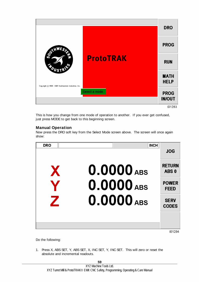
59 XYZ Machine Tools Ltd.
XYZ Turret Mill & ProtoTRAK EMX CNC Safety, Programming, Operating & Care Manual
This is how you change from one mode of operation to another. If you ever get confused, just press MODE to get back to this beginning screen.
Manual Operation Now press the DRO soft key from the Select Mode screen above. The screen will once again show:
Do the following:
1. Press X, ABS SET, Y, ABS SET, X, INC SET, Y, INC SET. This will zero or reset the absolute and incremental readouts.

60 XYZ Machine Tools Ltd.
XYZ Turret Mill & ProtoTRAK EMX CNC Safety, Programming, Operating & Care Manual
2. Press the INC/ABS key. Notice that the ABS on the screen changes to INC.
3. Manually crank the X handwheel so that the table moves left. Move the table so that the readout is X 10.00 INC. Manually crank the Y handwheel so that the saddle moves away from you. Move the saddle so that the readout is Y -10.00 INC.
4. Press X, INC SET and Y, INC SET to reset the X and Y incremental readout to zero.
5. Move X another inch to 10.00 INC and Y another inch to -10.00 INC.
6. Press the INC/ABS function key to show your absolute position. That is, how far you have moved from Step 1 above where you set absolute. X should read 20.00 ABS, and Y -20.00 ABS.
7. Press X, ABS SET, Y, ABS SET to reset absolute to the position you’re at now.
JOG
Do the following:
1. Fold up the X and Y handwheels (pull out, then fold up).
WARNING Never operate the ProtoTRAK under servo motor control unless the handles are
folded into their safe position.
2. Press the JOG soft key. A message in red will appear that says “CAUTION: JOG KEYS ARE ACTIVE”. This means the ProtoTRAK is ready to jog in the plus X or Y direction at 2540 mmpm, so if you press X or Y, the machine will move.
3. Press and hold X. The table moves to the left at 2540 mmpm. Release the X key to stop.
4. Press and hold Y. The table moves towards you. Release.
5. Press the +/- key. Notice the number in the Feed Rate box on the lower left of the screen changes from “2540” to “-2540”.
6. Press and hold X. The table now moves right. Release.
7. Press and hold Y. The saddle now moves away. Release.
8. Press the key. Notice the “JOG -2540 ipm” changes to “JOG -2286 ipm”. Press the key several more times.
9. Press and hold X. Notice the table moves slower. Release.
10. Press the key several times until you are back to “JOG -2540 ipm.”
11. Press number key 2, 0, 0. Notice that the conversation line now says "FEED RATE 200"
12. Press either X or Y. The table or saddle now moves at 200 mmpm. This is the way to get low feedrates for power feeding straight cuts in X or Y.
13. Press the RETN (Return) soft key to exit jog operation and go back to manual.
Return to Absolute Zero Do the following:
1. Make sure the readout is displaying absolute (ABS). If not, press the INC/ABS key.
2. Move the handwheels to make sure you’re not at zero.
3. Press the RETURN ABS 0 soft key.
4. Press GO. System prompts to “Check Z”, press GO again. The table and saddle will automatically move to the absolute zero you set earlier.

61 XYZ Machine Tools Ltd.
XYZ Turret Mill & ProtoTRAK EMX CNC Safety, Programming, Operating & Care Manual
13.3 Programming Sample The purpose of this sample is to demonstrate most of the various event types or canned geometries that can be programmed. Also to give you practice inputting data and running an actual part. If you don’t want to machine the part, just follow along with the instructions for how to use the ProtoTRAK EMX.
Preparation If you want to make this part, you will need the following.
A vice (if the vice does not have step jaws you will also need parallels).
A 6 mm drill.
A 10 mm, 2 flute, bottom cutting end mill.
An edge finder or wiggler.
A piece of 150 mm x 100 mm x 5 mm aluminum.
Program Strategy Before programming a part, take a moment to figure out what you want to do and what order you want to do it. The strategy for programming a ProtoTRAK EMX is quite straightforward:
Identify the geometry you want to machine from the print and the order you want to machine it, what to machine first, second, etc.
Select each geometry (event) on the control one at a time.
Answer the questions that define the geometry Our plan for this part is:
1. The lower left corner of the part will be our absolute zero, or absolute reference.
2. Drill the left-most hole in the row using a Drill Event.
62 XYZ Machine Tools Ltd.
XYZ Turret Mill & ProtoTRAK EMX CNC Safety, Programming, Operating & Care Manual
3. Drill the next 3 holes using a Repeat Event.
4. Drill the 8-hole bolt circle pattern using a Bolt Hole Event.
5. Mill the diagonal in the upper left corner using a Mill Event.
6. Mill the arc in the lower left corner using an Arc Event.
7. Mill the circular pocket with a Pocket Event.
8. Mill the through rectangle with a Frame Event.
Making and Inputting the Program Press MODE and then press PROG soft key to enter the Program Mode. The Program Part Number The conversation display says, “Program Name”. You input 123, SET (INC SET or ABS SET). Event 1 - The First Hole Conversation says, “Select Event”. You press POSN/DRILL soft key. Now, press ONE to
select the single hole.
The right side of the information area shows that Event 1 is a Position/Drill, and it lists what data are required. But keep your eye on the conversation line.
Conversation says, “X”. You press 68.75, ABS SET. Remember the lower left corner is our Absolute zero.
“Y”. You press 18.75, ABS SET.
“TOOL #”. Your press 1, SET.
Tool number 1 is the 6 mm drill, so press 6, SET.
Event 2 - The Next 3 Holes “Select Event”. You press the REPEAT soft key for Event 2 to make the next 3 holes in
the row.
Event 2 is a Repeat Event and the data needed are shown on the right of the information area. Notice Event 1 has shifted to the left.
“First Event #”. You press 1, SET because we want to repeat Event 1.
“Last Event #”. You press 1, SET because the only event we want to repeat is Event 1.
“X Offset”. You press 18.75, INC SET because that’s the distance between the holes in the X direction.
“Y Offset”. You press 0, INC SET because the other holes are not shifted in the Y direction.
“# Repeats”. You press 3, SET because we want 3 more holes each offset by 18.75.
“Tool #”. You press 1, SET because we’re using the same tool.
Event 3 - The Bolt Hole Pattern
“Select Event.” You press POSN DRILL, then the BOLT HOLE soft key for Event 3.
Event 2 has shifted to the left and the data you need to input are shown on the right.
“# Holes”. You press 8, SET because there are 8 holes.
“X CENTER”. You press 37.50, ABS SET.
“Y CENTER”. You press 62.50, ABS SET.
“Radius”. You press 25, SET because the radius of the bolt hole pattern is 25.00.

63 XYZ Machine Tools Ltd.
XYZ Turret Mill & ProtoTRAK EMX CNC Safety, Programming, Operating & Care Manual
“Angle”. You press 90, SET. This is the angle measured in the anti-clockwise direction from 3 o’clock to the first hole you want to drill. We could have input 0 and then we would drill the right most hole first.
“Tool #”. You press SET. We’re still using tool number 1, but notice we didn’t press the 1. If you don’t input a number, the ProtoTRAK assumes the last tool is used again.
"Tool Dia". You press SET.
Event 4 - The Upper Left Diagonal “Select Event”. You press MILL soft key for Event 4.
“X Begin”. You press 0, ABS SET to define the beginning of the milling cut at its lower left point on the diagonal.
“Y Begin”. You press 81.25, ABS SET to define the beginning of the milling cut.
“X End”. You press 12.50, ABS SET to define the end of the milling cut.
“Y End”. You press 18.75, INC SET to define the end of the milling cut. Notice we defined this as an incremental change of 18.75 mm from the beginning. We could have also input 100.00, ABS SET to also define the end point. Think about this and make sure you understand.
“CONRAD”. You press SET because we don’t want to blend this mill cut into another cut.
“Tool Offset”. You press 2, SET because you’re selecting that the tool is to the left of the work piece as it moves from beginning to end.
“Feedrate”. You press 125. , SET to mill at 125 mmpm.
“Tool #”. You input 2, SET because we’re calling the 10 mm end mill tool number 2.
"Tool Dia." Your press 10 SET.
“Continue”. You input “No.”, SET because this is not continuous path milling.
Event 5 - The Lower Left Radius “Select Event”. You input soft key ARC for Event 5.
“X Begin”. You input 0, ABS SET because we’re going to start at the top and mill down and right.
“Y Begin”. You input 12.50, ABS SET.
“X End”. You input 12.50, ABS SET.
“Y End”. You input 0, ABS SET.
“X Center”. You input 12.50, ABS SET, or we could have input 0, INC SET since the X Center is the same as the X End.
“Y Center”. You input 12.50, ABS SET.
“CONRAD”. You input 0, SET.
“Direction”. You input 2, SET because we are milling in an anti-clockwise direction.
“Tool Offset”. You input 1, SET because looking from beginning towards end (the direction of the tool cut) the tool is to the right of the work piece. Think about this to be sure you understand.
“Feedrate”. You input 125., SET.
“Tool #”. You input 2, SET because that’s still our tool.
"Tool Dia". You input 10 SET (or INC SET).
“Continue”. You input “No”, SET because this is not a continuous milling path.

64 XYZ Machine Tools Ltd.
XYZ Turret Mill & ProtoTRAK EMX CNC Safety, Programming, Operating & Care Manual
Event 6 - The Circular Pocket “Select Event”. You press POCKET FRAME soft key for Event 6.
“Select”. You press CIRCLE POCKET soft key because our pocket is circular.
“X Center”. You press 37.50, POCKET ABS SET.
“Y Center”. You press 62.50, ABS SET.
“Radius”. Your press 18.75, SET defining the radius of the pocket.
“Direction”. You press 1, SET to select clockwise tool motion. We could have just as easily selected counterclockwise.
“Fin Cut”. You press 0.5, SET to select a finish cut of 0.5 mm. When machining, the program will hog out the pocket 0.5 undersized then make a finish cut pass to the proper size.
“Feedrate”. You press 200, SET.
“Fin Feedrate”. You press 125, SET.
“Tool #”. You press SET.
"Tool Dia". You press SET.
Event 7 - The Through Rectangle “Select Event”. You press POCKET FRAME soft key for Event 7.
“Select”. You press RECT PROFILE soft key for the rectangular frame.
“X1”. You press 93.75, ABS SET which is the distance to corner number 1, which we will say is the lower left corner of the frame.
“Y1”. You press 43.75, ABS SET.
“X 3”. You press 37.50, INC SET because corner number 3 is the diagonal corner and it is 37.50 mm in the plus X direction from X1.
“Y3”. You press 31.25, INC SET.
“CONRAD”. You press 7.5, SET because the corner radius of the frame is 7.5 mm.
“Direction”. You press 2, SET to choose counterclockwise.
“Tool Offset.” You press 2, SET because when the tool moves counterclockwise around the inside of the rectangle frame, it is to the left of the work piece.
“Fin Cut”. You press 0.5, SET to select a 0.5 mm finish cut.
“Feedrate.” You press 125, SET.
“Fin Feedrate”. You press 50, SET.
“Tool #”. You press because we’re still using tool number 2.
"Tool Dia". You press SET.
Look at the Program Press the LOOK hard key to see what your program looks like. You don't have to finish the programming to see what you've done so far. Any time you see the SELECT EVENT prompt in the Program Mode, you can look at the part graphics. The drawn part should look like this:
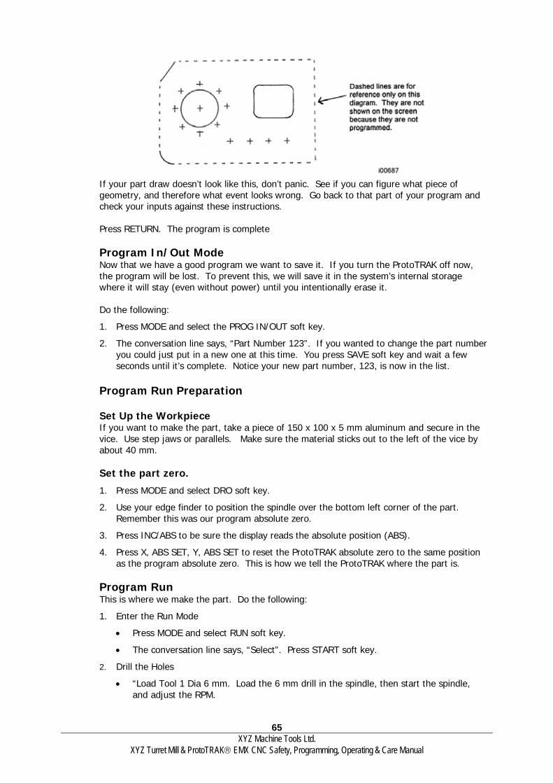
65 XYZ Machine Tools Ltd.
XYZ Turret Mill & ProtoTRAK EMX CNC Safety, Programming, Operating & Care Manual
If your part draw doesn’t look like this, don’t panic. See if you can figure what piece of geometry, and therefore what event looks wrong. Go back to that part of your program and check your inputs against these instructions.
Press RETURN. The program is complete
Program In/Out Mode Now that we have a good program we want to save it. If you turn the ProtoTRAK off now, the program will be lost. To prevent this, we will save it in the system’s internal storage where it will stay (even without power) until you intentionally erase it. Do the following:
1. Press MODE and select the PROG IN/OUT soft key.
2. The conversation line says, “Part Number 123”. If you wanted to change the part number you could just put in a new one at this time. You press SAVE soft key and wait a few seconds until it’s complete. Notice your new part number, 123, is now in the list.
Program Run Preparation Set Up the Workpiece If you want to make the part, take a piece of 150 x 100 x 5 mm aluminum and secure in the vice. Use step jaws or parallels. Make sure the material sticks out to the left of the vice by about 40 mm. Set the part zero.
1. Press MODE and select DRO soft key.
2. Use your edge finder to position the spindle over the bottom left corner of the part. Remember this was our program absolute zero.
3. Press INC/ABS to be sure the display reads the absolute position (ABS).
4. Press X, ABS SET, Y, ABS SET to reset the ProtoTRAK absolute zero to the same position as the program absolute zero. This is how we tell the ProtoTRAK where the part is.
Program Run This is where we make the part. Do the following:
1. Enter the Run Mode
Press MODE and select RUN soft key.
The conversation line says, “Select”. Press START soft key.
2. Drill the Holes
“Load Tool 1 Dia 6 mm. Load the 6 mm drill in the spindle, then start the spindle, and adjust the RPM.

66 XYZ Machine Tools Ltd.
XYZ Turret Mill & ProtoTRAK EMX CNC Safety, Programming, Operating & Care Manual
Note: You may want to centre drill each hole first. You can run each event more than once by pressing Mode, Run, Start. To start at the middle of the program, press START EVENT #.
X and Y readouts should read zero ABS. Beneath them the actual feedrate (now zero), and the feedrate override percent (now 100%) are shown.
Press GO. The tool will move (actually the table moves) to the first hole in the row.
“Set Z”. You move the quill and drill the hole. After every drilling operation always make sure the tool is up to clear the work piece.
Press GO and drill the remaining holes and holes in the bolt hole pattern each time the conversation line says “Set Z”.
3. Mill the Upper Left Diagonal
When the last hole is drilled the conversation line says, “Load Tool 2 Dia 10 mm. You should stop the spindle, load the 10mm end mill, start the spindle and adjust RPM.
Press GO. The tool will move to the upper left EMX of the part where the diagonal cut begins.
“Set Z”. You move the quill so the tool is slightly below the bottom of the plate to make the full depth cut. Lock the quill at this position.
Press GO. The tool will move at 125 mmpm and cut the diagonal.
“Check Z”. This is a warning to raise the quill because the next move will be at rapid speed (2540 mmpm). You should raise the tool.
4. Mill the Lower Left Radius
Press GO. The tool will rapid to the beginning position for the Arc cut.
“Set Z”. Lower the tool to the correct depth and lock the quill.
Press GO. The tool will move at 125 mmpm and cut the arc.
“Check Z”. You should raise the tool.
5. Mill the Circular Pocket
Press GO. The tool will rapid to about the centre of the pocket.
“Set Z.” Bring the tool down (or the turret up) to 3.0 mm below the top of the part and lock the quill.
Press GO. The tool will move at 200 mmpm to machine the pocket. Press the and keys while cutting the pocket to see how you can adjust the speed while you’re cutting. When the pocket is roughed out a little undersized, the cutter will automatically make the program 0.5 mm finish cut.
“Check Z”. You should raise the tool.
6. Mill the Through-Rectangle
Press GO. The tool will rapid to the beginning point to machine the rectangular frame thru.
“Set Z”. Move the quill down so that the tool is slightly below the bottom of the plate. Lock the quill.
Press GO. The tool will move at 125 mmpm (if you left the feedrate override at 100% when you adjusted and ) to machine the rectangle and make the finish pass.
“Run Over”. The part is finished. If you were making a second part and could locate it in the vise in the same place, you could now press the NEXT PART soft key and the whole program would be repeated.
Press MODE to exit Run.
Congratulations. You’ve Made Your First Part.
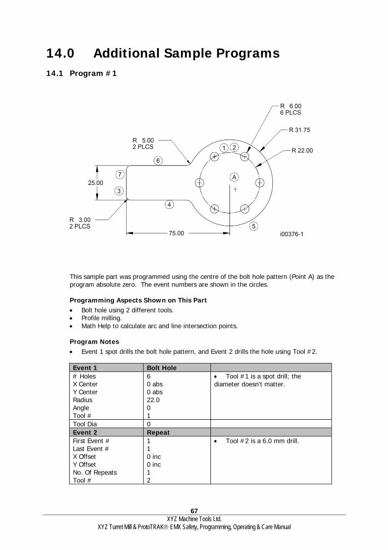
67 XYZ Machine Tools Ltd.
XYZ Turret Mill & ProtoTRAK EMX Safety, Programming, Operating & Care Manual
14.0 Additional Sample Programs 14.1 Program #1
This sample part was programmed using the centre of the bolt hole pattern (Point A) as the program absolute zero. The event numbers are shown in the circles.
Programming Aspects Shown on This Part Bolt hole using 2 different tools. Profile milling. Math Help to calculate arc and line intersection points.
Program Notes Event 1 spot drills the bolt hole pattern, and Event 2 drills the hole using Tool #2.
Event 1 Bolt Hole # Holes X Center Y Center Radius Angle Tool #
6 0 abs 0 abs 22.0 0 1
Tool #1 is a spot drill; the diameter doesn't matter.
Tool Dia 0 Event 2 Repeat First Event # Last Event # X Offset Y Offset No. Of Repeats Tool #
1 1 0 inc 0 inc 1 2
Tool #2 is a 6.0 mm drill.
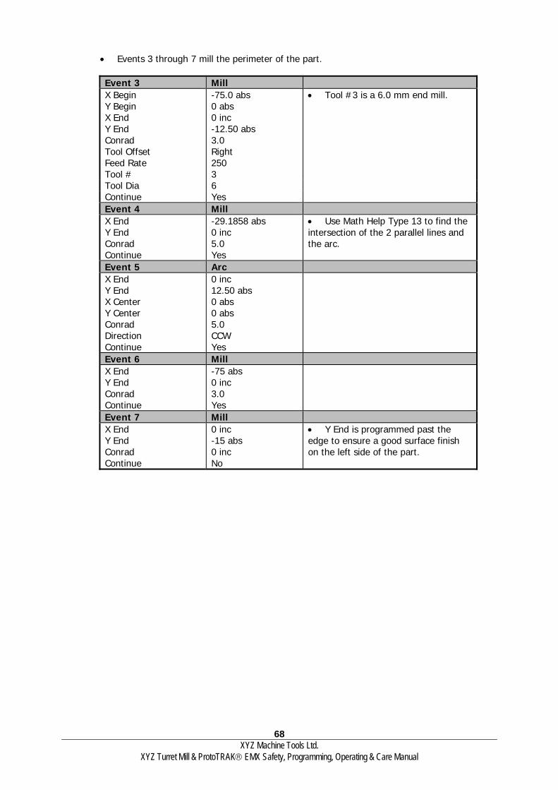
68 XYZ Machine Tools Ltd.
XYZ Turret Mill & ProtoTRAK EMX Safety, Programming, Operating & Care Manual
Events 3 through 7 mill the perimeter of the part.
Event 3 Mill X Begin Y Begin X End Y End Conrad Tool Offset Feed Rate Tool #
-75.0 abs 0 abs 0 inc -12.50 abs 3.0 Right 250 3
Tool #3 is a 6.0 mm end mill.
Tool Dia 6 Continue Yes Event 4 Mill X End Y End Conrad Continue
-29.1858 abs 0 inc 5.0 Yes
Use Math Help Type 13 to find the intersection of the 2 parallel lines and the arc.
Event 5 Arc X End Y End X Center Y Center Conrad Direction Continue
0 inc 12.50 abs 0 abs 0 abs 5.0 CCW Yes
Event 6 Mill X End Y End Conrad Continue
-75 abs 0 inc 3.0 Yes
Event 7 Mill X End Y End Conrad Continue
0 inc -15 abs 0 inc No
Y End is programmed past the edge to ensure a good surface finish on the left side of the part.

69 XYZ Machine Tools Ltd.
XYZ Turret Mill & ProtoTRAK EMX Safety, Programming, Operating & Care Manual
14.2 Program # 2
This sample part was programmed using the centre of the circular pocket (Point A) as the program absolute zero. The event numbers are shown in the circles.
Programming Aspects Shown on This Part Bolt hole using 2 different tools. Circular Pocket. Profile milling. Math Help to calculate arc and line tangency points.
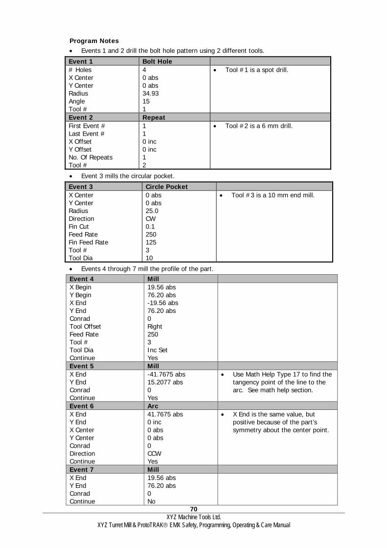
70 XYZ Machine Tools Ltd.
XYZ Turret Mill & ProtoTRAK EMX Safety, Programming, Operating & Care Manual
Program Notes Events 1 and 2 drill the bolt hole pattern using 2 different tools.
Event 1 Bolt Hole # Holes X Center Y Center Radius Angle Tool #
4 0 abs 0 abs 34.93 15 1
Tool #1 is a spot drill.
Event 2 Repeat First Event # Last Event # X Offset Y Offset No. Of Repeats Tool #
1 1 0 inc 0 inc 1 2
Tool #2 is a 6 mm drill.
Event 3 mills the circular pocket.
Event 3 Circle Pocket X Center Y Center Radius Direction Fin Cut Feed Rate Fin Feed Rate Tool # Tool Dia
0 abs 0 abs 25.0 CW 0.1 250 125 3 10
Tool #3 is a 10 mm end mill.
Events 4 through 7 mill the profile of the part.
Event 4 Mill X Begin Y Begin X End Y End Conrad Tool Offset Feed Rate Tool # Tool Dia Continue
19.56 abs 76.20 abs -19.56 abs 76.20 abs 0 Right 250 3 Inc Set Yes
Event 5 Mill X End Y End Conrad Continue
-41.7675 abs 15.2077 abs 0 Yes
Use Math Help Type 17 to find the tangency point of the line to the arc. See math help section.
Event 6 Arc X End Y End X Center Y Center Conrad Direction Continue
41.7675 abs 0 inc 0 abs 0 abs 0 CCW Yes
X End is the same value, but positive because of the part’s symmetry about the center point.
Event 7 Mill X End Y End Conrad Continue
19.56 abs 76.20 abs 0 No
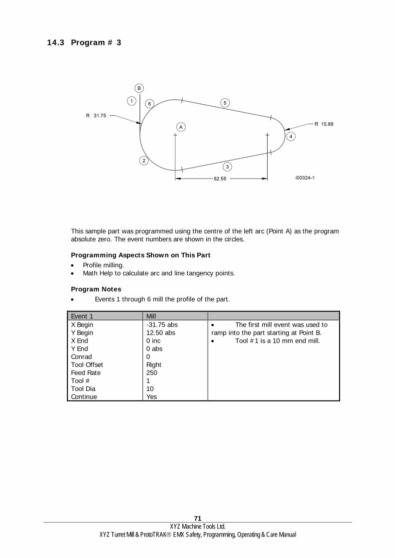
71 XYZ Machine Tools Ltd.
XYZ Turret Mill & ProtoTRAK EMX Safety, Programming, Operating & Care Manual
14.3 Program # 3
This sample part was programmed using the centre of the left arc (Point A) as the program absolute zero. The event numbers are shown in the circles.
Programming Aspects Shown on This Part Profile milling. Math Help to calculate arc and line tangency points.
Program Notes Events 1 through 6 mill the profile of the part. Event 1 Mill X Begin Y Begin X End Y End Conrad Tool Offset Feed Rate Tool # Tool Dia Continue
-31.75 abs 12.50 abs 0 inc 0 abs 0 Right 250 1 10 Yes
The first mill event was used to ramp into the part starting at Point B. Tool #1 is a 10 mm end mill.
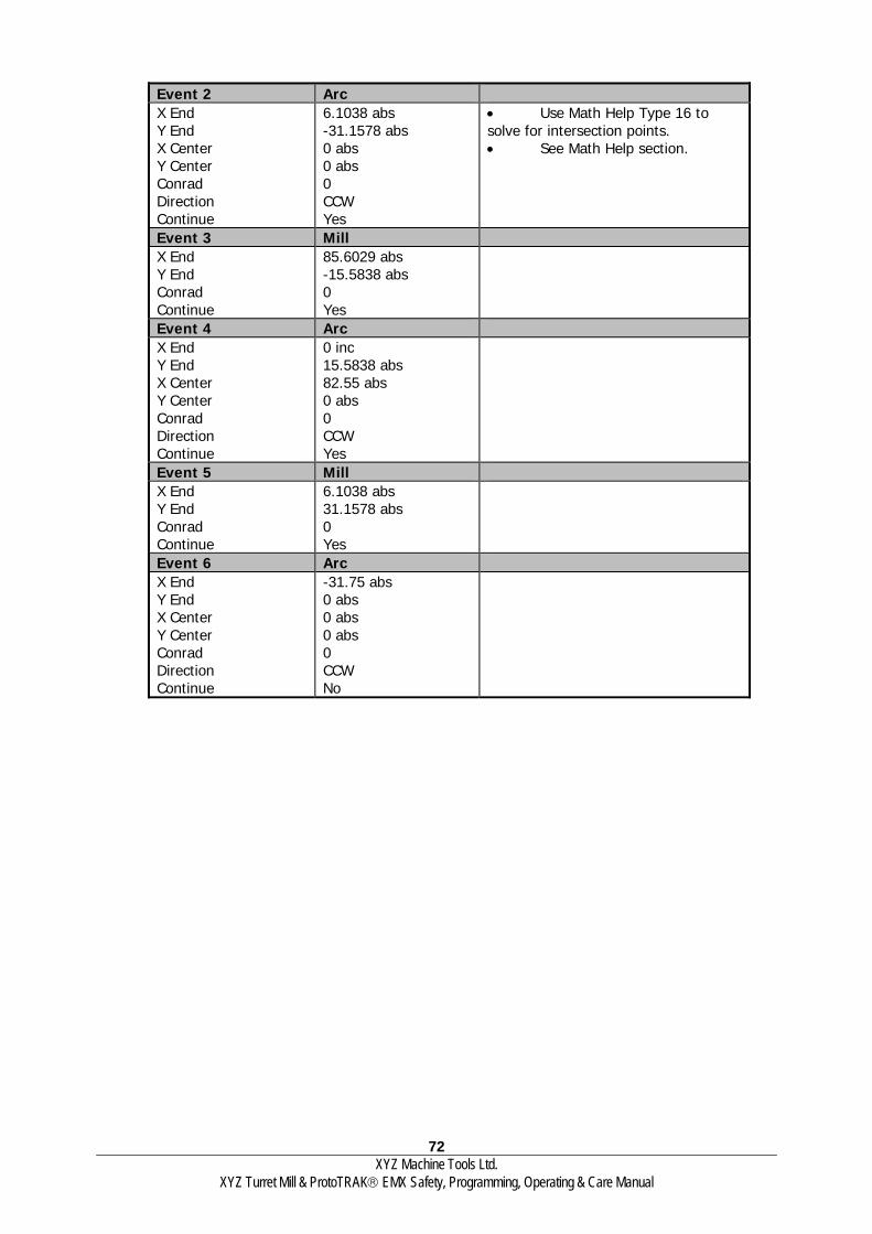
72 XYZ Machine Tools Ltd.
XYZ Turret Mill & ProtoTRAK EMX Safety, Programming, Operating & Care Manual
Event 2 Arc X End Y End X Center Y Center Conrad Direction Continue
6.1038 abs -31.1578 abs 0 abs 0 abs 0 CCW Yes
Use Math Help Type 16 to solve for intersection points. See Math Help section.
Event 3 Mill X End Y End Conrad Continue
85.6029 abs -15.5838 abs 0 Yes
Event 4 Arc X End Y End X Center Y Center Conrad Direction Continue
0 inc 15.5838 abs 82.55 abs 0 abs 0 CCW Yes
Event 5 Mill X End Y End Conrad Continue
6.1038 abs 31.1578 abs 0 Yes
Event 6 Arc X End Y End X Center Y Center Conrad Direction Continue
-31.75 abs 0 abs 0 abs 0 abs 0 CCW No
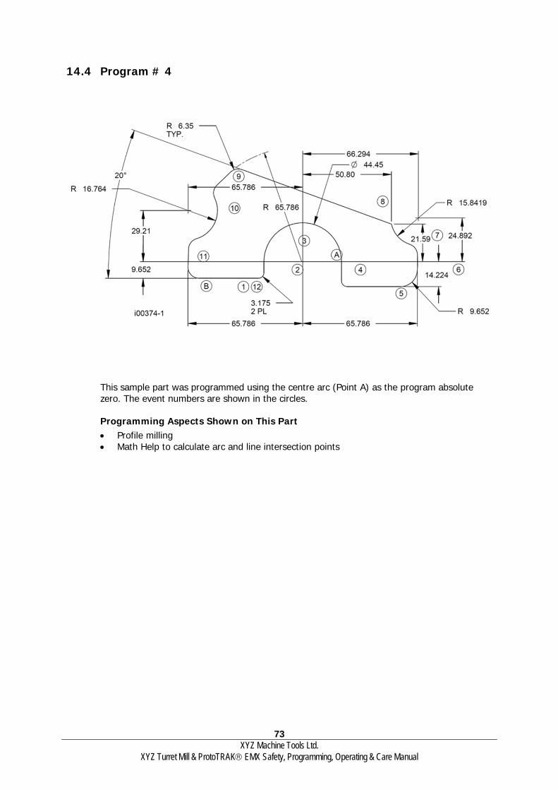
73 XYZ Machine Tools Ltd.
XYZ Turret Mill & ProtoTRAK EMX Safety, Programming, Operating & Care Manual
14.4 Program # 4
This sample part was programmed using the centre arc (Point A) as the program absolute zero. The event numbers are shown in the circles.
Programming Aspects Shown on This Part Profile milling Math Help to calculate arc and line intersection points
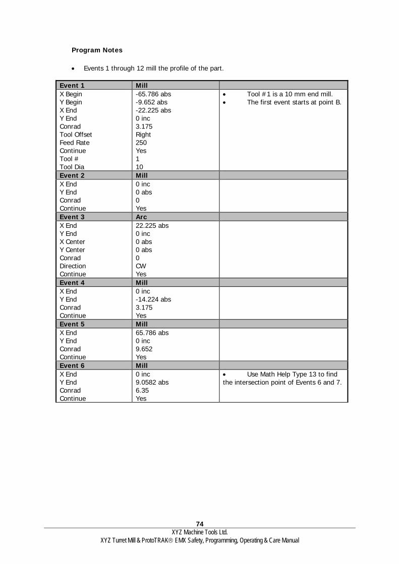
74 XYZ Machine Tools Ltd.
XYZ Turret Mill & ProtoTRAK EMX Safety, Programming, Operating & Care Manual
Program Notes Events 1 through 12 mill the profile of the part.
Event 1 Mill X Begin Y Begin X End Y End Conrad Tool Offset Feed Rate Continue Tool # Tool Dia
-65.786 abs -9.652 abs -22.225 abs 0 inc 3.175 Right 250 Yes 1 10
Tool #1 is a 10 mm end mill. The first event starts at point B.
Event 2 Mill X End Y End Conrad Continue
0 inc 0 abs 0 Yes
Event 3 Arc X End Y End X Center Y Center Conrad Direction Continue
22.225 abs 0 inc 0 abs 0 abs 0 CW Yes
Event 4 Mill X End Y End Conrad Continue
0 inc -14.224 abs 3.175 Yes
Event 5 Mill X End Y End Conrad Continue
65.786 abs 0 inc 9.652 Yes
Event 6 Mill X End Y End Conrad Continue
0 inc 9.0582 abs 6.35 Yes
Use Math Help Type 13 to find the intersection point of Events 6 and 7.
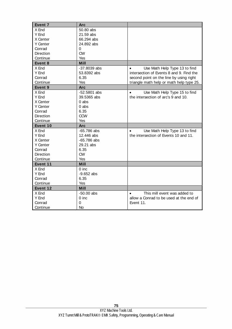
75 XYZ Machine Tools Ltd.
XYZ Turret Mill & ProtoTRAK EMX Safety, Programming, Operating & Care Manual
Event 7 Arc X End Y End X Center Y Center Conrad Direction Continue
50.80 abs 21.59 abs 66.294 abs 24.892 abs 0 CW Yes
Event 8 Mill X End Y End Conrad Continue
-37.8039 abs 53.8392 abs 6.35 Yes
Use Math Help Type 13 to find intersection of Events 8 and 9. Find the second point on the line by using right triangle math help or math help type 25.
Event 9 Arc X End Y End X Center Y Center Conrad Direction Continue
-52.5801 abs 39.5365 abs 0 abs 0 abs 6.35 CCW Yes
Use Math Help Type 15 to find the intersection of arc’s 9 and 10.
Event 10 Arc X End Y End X Center Y Center Conrad Direction Continue
-65.786 abs 12.446 abs -65.786 abs 29.21 abs 6.35 CW Yes
Use Math Help Type 13 to find the intersection of Events 10 and 11.
Event 11 Mill X End Y End Conrad Continue
0 inc -9.652 abs 6.35 Yes
Event 12 Mill X End Y End Conrad Continue
-50.00 abs 0 inc 0 No
This mill event was added to allow a Conrad to be used at the end of Event 11.
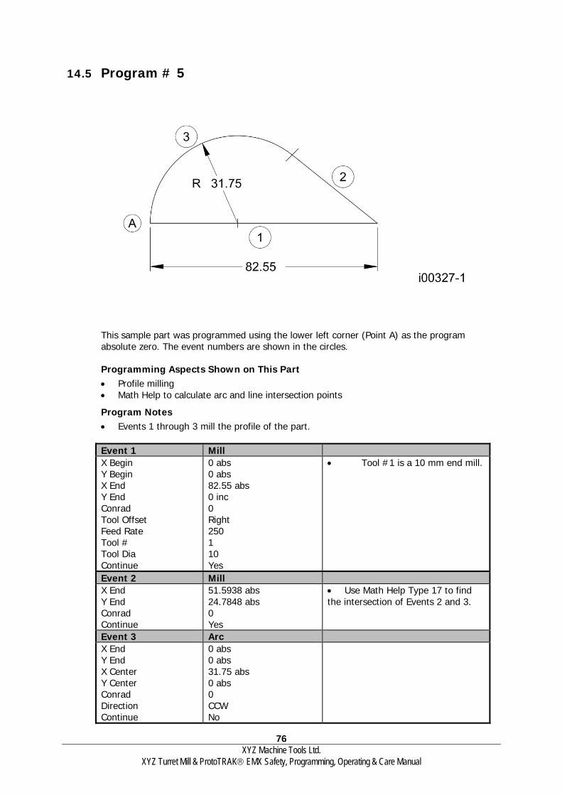
76 XYZ Machine Tools Ltd.
XYZ Turret Mill & ProtoTRAK EMX Safety, Programming, Operating & Care Manual
14.5 Program # 5
This sample part was programmed using the lower left corner (Point A) as the program absolute zero. The event numbers are shown in the circles.
Programming Aspects Shown on This Part Profile milling Math Help to calculate arc and line intersection points
Program Notes Events 1 through 3 mill the profile of the part. Event 1 Mill X Begin Y Begin X End Y End Conrad Tool Offset Feed Rate Tool # Tool Dia Continue
0 abs 0 abs 82.55 abs 0 inc 0 Right 250 1 10 Yes
Tool #1 is a 10 mm end mill.
Event 2 Mill X End Y End Conrad Continue
51.5938 abs 24.7848 abs 0 Yes
Use Math Help Type 17 to find the intersection of Events 2 and 3.
Event 3 Arc X End Y End X Center Y Center Conrad Direction Continue
0 abs 0 abs 31.75 abs 0 abs 0 CCW No

77 XYZ Machine Tools Ltd.
XYZ Turret Mill & ProtoTRAK EMX Safety, Programming, Operating & Care Manual
XYZ Machine Tools Ltd.
ProtoTRAK UK Warranty Policy Warranty ProtoTRAK products are warranted to the original purchaser to be free from defects in workmanship and materials for the following periods:
Product Warranty Period
New ProtoTRAK Machine 12 Months
Any Exchange Unit or Spare Part 6 Months
The warranty period starts on the date of the invoice to the original purchaser from XYZ Machine Tools Ltd (XYZ) or their authorised distributor.
If a unit under warranty fails, it will be repaired or exchanged at our option for a properly functioning unit in similar or better condition. Such repairs or exchanges will be made carriage paid within the UK mainland.
Disclaimers of Warranties This warranty is expressly in lieu of any other warranties, express or implied, including any implied warranty of merchantability or fitness for a particular purpose, and of any other obligations or liability on the part of XYZ (or any producing entity, if different).
Warranty repairs/exchanges do not cover incidental costs such as installation, labour, etc.
XYZ is not responsible for consequential damages from use or misuse of any of its products.
ProtoTRAK products are precision mechanical/electromechanical measurement systems and must be given the reasonable care that these types of instruments require.
Replacement of slideway wipers and covers is the responsibility of the customer. Consequently, the warranty does not apply if swarf or coolant have been allowed to enter the mechanism.
Accidental damage, beyond the control of XYZ, is not covered by the warranty. Thus, the warranty does not apply if an instrument has been abused, dropped, hit, disassembled or opened.
Improper installation by or at the direction of the customer in such a way that the product consequently fails, is considered to be beyond the control of the manufacturer and outside the scope of the warranty.