xplora concrete mount sys install man - sayfa group
TRANSCRIPT

PROPRIETARY ANCHOR POINT SYSTEM FOR SAFE WORK AT HEIGHT
SYST
EM IN
STAL
LATI
ON
M
ANUA
L
SYSTEM CONTENTS
In-Action 2
Features 3
Installation Requirements 4
Limitations 5
Design & Layout 6
Configurations 11
Tools & Equipment 12
Australian Standards 13
Installation Procedure 14
Installation Checklist 23
Maintenance 24
Technical 26
Warranty 28
Specifications 29
1300 301 755 SAYFA.COM.AU
MUST BE READ AND UNDERSTOOD PRIOR TO INSTALLATION
CONCRETE MOUNT ANCHORS

XPLORA®
ABSEIL / FALL ARREST CONCRETE FIX ANCHORS
5
9
7
3
11
8
10
2
4
1
12
6
IT’S THE SAYFA WAY
Sayfa Group leads the industry in the design, installation and management of access, fall protection and ground safety systems.
The In-Action model demonstrates access, fall and ground protection requirements for a commercial building design.
SayfaGrouprecommendationsfulfillcurrentworkplacerequirementsfor the safety of building maintenance subcontractors, employees and the general public.
# DESCRIPTION
1 3 SIXTY Fall arrest anchors
2 TRAVEL 8 Rooforwallmountstaticlines
3 SENTRY Roof mount guardrails
4 ON-TRAK Roofwalkways(yelloworgrey)
5 PROTEX Skylight protectors
6 RAPTOR Overhead fall arrest rails
For more information, please contact Sayfa Group directly.
# DESCRIPTION
7 KATT Modular fixed ladders
8 VISTA Modularfolddownladders
9 ALTO Step ladders & step bridges
10 ALTO Stairs & platforms
11 MODDEX Handrails & balustrades
12 SKYDORE Roof access hatches

3
XPLORA® FOR PERSONNEL WORKING AT HEIGHT USING A HARNESS AND LANYARD FALL PROTECTION SYSTEM
FEATURES & BENEFITS (AP127 CONCRETE MOUNT ANCHOR WITH REMOVABLE EYE)
M16 X 50MM EYE - Easy attachment of rope lanyard, karabiner or snaphook
CONCRETE INSERT - High strength stainless steel insert - 100mm penetration into concrete structure
DEFORMED SHANK - Increased load performance due to irregular formation - Allows for easier flow of chemical epoxy if used as a glued in anchor
WITH REMOVEABLE EYEBOLTFOR PUBLIC SAFETY The eyebolt is designed to be removed from the concrete threaded insert to avoid trip hazards when installed in public areas or where controlled use is required. A stainless steel cap protects the insert from dirt when the eyebolt is not in use. NOTE: Removeable eyebolt must be threaded into sleeve by a minimum of 20mm or 10 full turns.
UN
IQU
EPRO
DU
CT FEATURE
PATENTS AND DESIGN REGISTRATIONS APPLY
IDENTITY NUMBER - Allows traceability and identification
THREADED EYE BOLT - Removeable eye when used in a trafficable locations and where controlled use is required
STAINLESS STEEL CAP - Protects insert thread from dirt when eye bolt is removed

INSTALLATION REQUIREMENTS
Sayfa Group instructions and recommendations, drawings and diagrams, and all other documentation are copyright, errors and omissions excepted, and must be carefully read and implemented. Any assistance or guidance given is without prejudice, and Sayfa Group cannot be held responsible for any inaccuracy or misinterpretation whatever. Failure to follow site installation requirements and warnings, may result in serious injury or death. Sayfa Group accepts no direct or indirect responsibility and/or consequential liability whatever, for any products and systems incorrectly installed or certified. Sayfa Group cannot warrant the integrity or suitability of the structure to which the products may be attached. Prior assessment must be made by a qualified structural engineer, unless the structure is authorised or approved by a competent person.
MUST BE READ PRIOR TO INSTALL
1. This system must only be installed by competent persons trained in the selection, use and maintenance of fall arrest and rope access systems.
2. Installers must and hold a current Sayfa approved installer certificate, possess valid industry licenses, be appropriately trained, and comply with all relevant WHS legislation prior to installation of this product.
3. Persons installing this system are required to have a comprehensive knowledge of the Australian Standards, codes of practice and industry guidelines that relate to the selection, use and maintenance of fall arrest and rope access systems and equipment.
4. Integrity and suitability of the structure to which this system is attached must be approved by a structural engineer unless it is clear to a competent person as to the structure suitability.
5. Read installation and operating instructions carefully before commencing any work. Consent to deviate from the installation guide must be obtained in writing from the manufacturer.
6. XPLORA glued in anchors using a chemical epoxy are recommended to use HILTI RE500 or equivalent. Correct hole size, depth, cleanliness preparation and insertion or epoxy adhesive as per manufacturers recommendations is critical.
7. Conduct an initial work/risk assessment, and take all reasonable precautions to eliminate or control potential hazards and risks during the installation of this product.
8. Complete all necessary WHS documentation, including a Job Safety Analysis and Work Method Statement and obtain consent from responsible person in the workplace prior to commencement of work.
9. Appropriate temporary access and safety equipment must be used during installation, such as platform ladders or scaffolding and fall protection anchorage points.
10. Do not modify or remove any element of the support structure without prior authorisation by a qualified engineer.
11. Decorative coatings and coverings must be removed to ensure correct evaluation of structure prior to attachment of system
12. Any re-routing of electrical and/or other services must be carried out by qualified or authorised personnel.
13. In case of emergency, fall arrest and rope access systems must be installed by a minimum of two persons.
14. Do not tamper with, modify or remove any part this system unless authorised by the manufacturer.
15. Appropriate labels or markings must be attached to each anchor and include the following:- System for personnel use only- Service entry date- Next examination/service due date- Harness gear requirements and system compatibility- Maximum designed load ratings- Installer/Certifier contact details
16. Documentation confirming correct use and maintenance of the system and equipment must be provided to the workplace manager on completion of installation. (See operation manual).
4

5
LIMITATIONS
MUST BE READ PRIOR TO USE
1. Structural requirements for attachment of Xplora concrete mount anchors: minimum 25MPa concrete, 150mm thick with reinforcing.
Confirmation of concrete structural suitability must be obtained from a structural engineer. Fixing anchors to brick, hollow blockwork or stone structure is not recommended.
2. The Xplora anchor is suitable for single (1) person use and rescue in the case of a fall incident. (15kN)
3. Only to be used by competent persons with proof of training by a Registered Training Organisation (RTO) in the use fall protection and rope access systems.
4. Fall arrest and rope access equipment is susceptible to deterioration when exposed to chemicals or hazardous environments and must be approved by the manufacturer for use in these applications.
5. This system, under normal use and environment, has a life expectancy of up to 10 years. A manufacturer’s assessment and certification to confirm suitability for an additional 5 years use is recommended. This will depend on location, usage and scheduled maintenance as per manufacturer and legislative requirements.
6. The Xplora anchor glued into concrete using a chemical epoxy will require proof load testing prior to commissioning into service and then at least 12 monthly intervals thereafter. Depending on anchor rating. A 3 minute test load to 50% the ultimate design load must be
performed. Anchors that have been cast into the concrete during construction of the slab structure do not require load testing.
7. Glued in or friction fit anchors must not be used in tension (pull out).Always position anchor to be loaded in shear.
8. Operators of this system must be connected via a lanyard with a personal energy absorber when used as a fall arrest system in accordance to Australian Standard AS/NZS 1891.1.
9. When installing this system as a rope access/abseil system, separate anchors must be provided for the working rope line and the safety back up rope line.
10. Do not exceed maximum number of users/persons per system. See specific system data plate for user configuration.
11. Do not tamper with or make alterations to system components without manufacturer’s consent.
12. This system is not to be used for tethering or lifting machinery or equipment.
13. The safety system must be recertified by a competent height safety inspector as recommended (or as per statutory requirements): - Non corrosive/mild environment – 12 monthly. - Corrosive/harsh environment – 6 monthly (more frequent inspection may be required).
Sayfa recommends that persons using fall arrest and rope access systems do not work alone in case of an emergency and help is required. Should any part of the system/equipment have been subjected to abnormal loading, use must be discontinued until replaced/recertified by a competent height safety inspector.

DESIGN & LAYOUT
This document does not in any way replace the full Australian Standard document AS/NZS 1891 & AS/NZS 4488 which must be read and properly and understood prior to installation of this system.
MUST BE READ PRIOR TO INSTALL
1. The hierarchy of risk control must be followed at all times.
It is important to note that the lower the hierarchy of control, the greater the skill of the operator required and therefore is least preferred compared with a higher hierarchy requiring minimal operator skill and less risk of operator injury as a result of incompetence.
2. Professional guidance on the design and set out of this system should be obtained prior to installation.
3. Certain environments produce acidic atmospheric conditions which are detrimental to steel structures and concrete surfaces. Any acidic environment must be assessed and structural components certified by a competent person prior to installation of this system.
4. Australian Standard AS/NZS 5532 does require each sub-structure type to which a fall arrest anchor system is attached to be individually tested and certified for safe use by the manufacturer.
5. When designing or positioning fall arrest and rope access systems it is important to check the following:- Roof pitch over 15° will require constant user attachment- Sub-structure type will determine best suited fixing method- Number of persons required to work in the same area will determine preferred type of fall protection system provided- Type of work to be done will determine best suited fixing type of fall protection system provided- How frequent the area will need to be accessed will determine preferred type of fall protection system provided- Safe access to the work zone will determine preferred type of access system to be used such as ladder or stairway system.
6. Where possible, anchorage systems should always be positioned above the operator to minimise unnecessary fall distance.
7. Drilled in or glued in anchors must not be positioned to allow tensile loads to be applied (Direct pullout).
Where a tensile load is required the anchor must be a non friction type anchor. i.e. either cast in or through bolted.
8. When connected to an anchorage system using a rope line lanyard, the anchorage must be placed a sufficient distance behind the operator to limit angle on lanyard to 20˚. This is to avoid excessive tensile load on the anchor.
9. When positioning the anchor system it is important to ensure that there is no possibility of pendulum action should the operator accidentally fall as a result of incorrect anchor spacing between fall edge and spacing between anchorages.
10. When installing this system as a rope access/abseil system, seperate anchors must be provided for the working rope line and the safety back up rope line.
11. Primarily anchors must be positioned in the ‘safe zone’ a minimum of 2.5M from fall edge of the roof area ensuring operator safety whilst connecting to the system prior to moving into the danger zone area.
12. Anti pendulum or diversion anchors must be provided to allow rope line extension into extreme corners preventing pendulum action in the case of a fall.
13. Sufficient fall clearance is essential in order to ensure correct operation of the system in a fall situation (see drawing page 26). Should fall distance be less than 5.0M, anchorage system must be positioned at least 2.0M or more from the fall edge to allow operator to work effectively in full restraint.
✔ Correct anchor positioning and rope line length
✔ Incorrect rope line length, operator could pendulum fall off roof. A diversion anchor is required in the corner location.
✔ Incorrect anchor positioning allows dangerous pendulum fall off roof
6

DESIGN & LAYOUT
ANCHOR LAYOUT ON SMALL ROOFS FOR FALL ARREST USE
Roofs up to 20.0M in width
ANCHOR LAYOUT ON LARGE ROOFS FOR FALL ARREST USE
Roofs over 20.0M in width
Notes:
• Avoid positioning an anchor more than 10.0M from the roof edge. Further than this will require longer than standard rope line (15.0M) which is heavy and cumbersome to manage. • Never allow more than 6.0M between anchors as this will create large ‘dead zone’ areas at the roof edge causing a pendulum fall possibility. • The primary anchor (or reference anchor) must always be placed such that the distance away from the gutter edge of the roof is the same as from the gable end of the roof.
For roof pitches above 15° Sayfa recommend that 100% attachment of the operator be maintained at all times.
These diagrams are a guide only. All risks must be clearly identified and eliminated as far as reasonably practicable.
7
Notes: • All points mentioned for smaller roofs also apply to larger roofs. • Avoid positioning anchors in close proximity to roof lights as these are classified as fall hazards. Ensure roof lights or skylights are protected with fall protection covers should an anchorage be positioned in close proximity.
Anchor LayoutRoofs up to 20m in width -
Anchors in centre of roof
20M
10M
10M 6M Not more than 6M
Notes:• Never go more than 10m from the edge. Further than this will require special harness equipment.• Never go more than 6m between anchors as this will create large 'dead zone' areas• The Primary Anchor (or reference anchor) must always be placed such that the distance away from the sides are the
same (positioning of purlins my restrict this slightly)• When the anchor distance away from the fall edge exceeds 6m, the distance between the anchors MUST NOT exceed
6m - ie, if the spacing away from the fall edge is 8m, the forst anchor will be 8m away from the edge but the concecutive anchors will be spaced at 6m apart.
Primary anchor(Reference anchor or�rst anchor to be installed)
Primary anchor(Reference anchor)
20m
Plu
s
6m
6m or
less
6m
Divide the last few anchor to get even spacing
Work out the positioning of these anchors first

8
DESIGN & LAYOUT
ANCHOR LAYOUT FOR ROPE ACCESS USE - OPTION 1
2.5M CENTRES UP TO 1.0MPRIMARY ANCHOR
SAFETY / BACKUP ANCHOR
ROOF DECK
EXTENT OF FACADE TO BE ACCESSED
WORKING ROPE
BACKUP/SAFETY ROPE
MAX 120°PREFERRED 90°
EXTENT OF FACADE TO BE ACCESSED
ROOF DECK
WORKING ROPE
BACKUP/SAFETY ROPELATERAL DIVERSION LANYARD
EXTE
NT
OF
FAC
AD
E TO
BE
AC
CES
SED
EXTE
NT
OF
FAC
AD
E TO
BE
AC
CES
SED
LATERAL DIVERSION LANYARD
ANCHOR LAYOUT FOR ROPE ACCESS USE - OPTION 2
• This layout is used where anchors are positioned closer than 4.0M to the edge• Anchors positioned within 3.0M of the roof edge will require fall protection to be provided to allow operator to safely connect rope lines and hardware.• This layout will allow access to the complete facade area for both window cleaning and maintenance.• Anchor pairs spaced greater than 2.5M may restrict access to specific locations especially if maintenance such as caulking is required.
• This layout is used when the anchors are positioned further than 6.0M from the edge.• Working ropes are positioned using a lateral diversion lanyard connected to either a primary or diversion anchor.

9
DESIGN & LAYOUT
ROPE ACCESS SYSTEM DESIGN LIMITATIONS
1. Design and installation of rope access systems must be in accordance with the requirements of AS/NZS4488.
2. Primary rope access anchors require a minimum ultimate design load of 12kN (single person use).
3. Appropriate labels or markings must be clearly visible on each anchor and include the following: - Ultimate design load - Limitations of the system - Number of persons allowed per anchor - Next service date - Installer / certifier info
4. Sayfa recommends that the design layout and installation of any rope access system is done by a fully trained and competent person with a level 3 rope access industry certificate.
5. All structural loadings/forces on parapets, awnings and sunshades or canopies to be calculated and authorised by a qualified engineer.
6. Any awning, sunshade or canopy less than 3.0M below top of parapet must be trafficable to allow operator to stand on whilst traversing past the canopy edge.
7. Any structural componentry required for rope access loads (12kN) will need to be designed and approved by a qualified engineer.
8. Any rope access anchorages placed within 3.0M of a fall edge, will require adequate fall protection to be provided for operator to access and attach to the rope access system safely.
9. Adequate protection for rope lines over sharp or fragile edges must be provided in accordance with current industry codes of pratice and guidelines.
10. Any davit arm system that requires a base mount configuration will need to be designed and certified by a qualified engineer.
11. All products/systems to comply with relevant Australian Standards; WHS Regulations and Codes of Practice.
1
REVISIONS REMARKSDate
2345
SAYFA SYSTEMS CONFIDENTIAL MATERIALThis drawing is copyright© and all rights are reserved. The design and specifications contained herein are confidential and the property of SAYFA SYSTEMS. The information may not be divulged or used in any form or by any means, for any purpose other than that stated by SAYFA SYSTEMS. Storage, transmittal, forwarding to third party, copying, reproduction, viewing or scanning of this Drawing by any person or party, whether in whole or in part is prohibited, except with express prior written consent by SAYFA SYSTEMS. The perspective is only an indication of the planned installation.
Drawing No.
RepBySayfa Group1029 Mountain HighwayBoronia Vic 3155Tel:- 03 8727 9000Fax:- 03 8727 9002Email:- [email protected]:- www.sayfa.com.au
14/1/15
5475
...
...
...
...
Proofing MV
30/6/15 MV
Anchor design - Drawings
AluminiumMaterial
ProductCode FAB NO:
20°M
AX*
1M MAX(600mm PREFERRED)
TYPICAL SUNSHADE(Sunshade will need to beconstructed as trafficable if less than3.0M below top of parapet.)
ABSEIL ROPE LINE
ANCHOR POINTLOAD RATED AT 12kN
ANCHOR IN REAR OF CONCRETE PARAPET(LOAD MUST BE IN SHEAR)*
ULTIMATE LOAD - 12kN LOWER FLOOR
SAFE ACCESS TO AND OVERPARAPET MUST BE PROVIDED LOAD POINTS!!
!(To be designed and certified by a Structural Engineer.)
!
Note: Diagram not to scale. For illustration purposes only.
Dra
win
g N
o. 5
475
10
DESIGN & LAYOUT
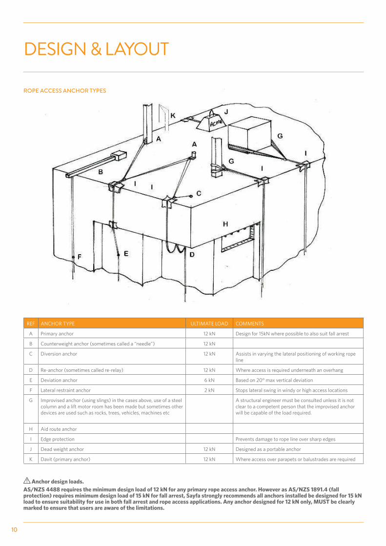
ROPE ACCESS ANCHOR TYPES
Anchor design loads.AS/NZS 4488 requires the minimum design load of 12 kN for any primary rope access anchor. However as AS/NZS 1891.4 (fall protection) requires minimum design load of 15 kN for fall arrest, Sayfa strongly recommends all anchors installed be designed for 15 kN load to ensure suitability for use in both fall arrest and rope access applications. Any anchor designed for 12 kN only, MUST be clearly marked to ensure that users are aware of the limitations.
REF ANCHOR TYPE ULTIMATE LOAD COMMENTS
A Primary anchor 12 kN Design for 15kN where possible to also suit fall arrest
B Counterweight anchor (sometimes called a “needle”) 12 kN
C Diversion anchor 12 kN Assists in varying the lateral positioning of working rope line
D Re-anchor (sometimes called re-relay) 12 kN Where access is required underneath an overhang
E Deviation anchor 6 kN Based on 20° max vertical deviation
F Lateral restraint anchor 2 kN Stops lateral swing in windy or high access locations
G Improvised anchor (using slings) in the cases above, use of a steel column and a lift motor room has been made but sometimes other devices are used such as rocks, trees, vehicles, machines etc
A structural engineer must be consulted unless it is not clear to a competent person that the improvised anchor will be capable of the load required.
H Aid route anchor
I Edge protection Prevents damage to rope line over sharp edges
J Dead weight anchor 12 kN Designed as a portable anchor
K Davit (primary anchor) 12 kN Where access over parapets or balustrades are required

CONFIGURATIONS
11
AP 118 - CONCRETE MOUNT ANCHOR WITH SLEEVE (PAGE 16) AP 124 - THROUGH BOLT ANCHOR POINT (PAGE 17)
AP 126 - CONCRETE MOUNT ANCHOR KIT WITH TORQUE INDICATOR (PAGE 20)
AP 127 - CONCRETE MOUNT ANCHOR (PAGE 21)
AP 125.10 - CONCRETE MOUNT ANCHOR (PAGE 18) AP 125.20 - CONCRETE MOUNT SWIVEL ANCHOR (PAGE 19)
AP 129.10 - CONCRETE CAST IN ANCHOR POINT (PAGE 22) Anchors that will not be easily accessible for load testing must be one of the following (these do not require load testing):
- AP 124 Through bolt anchor - AP 129.10 Cast in anchor with reinforcing

TOOLS & EQUIPMENT
Sayfa recommends that persons installing and using fall arrest systems do not work alone in case of an emergency and help is required.
IMPACT DRILL AND MASONARY DRILL BIT (CHECK SPECIFIC ANCHOR SIZE)
HOLE CLEANING BLOWER
HOLE CLEANING BRUSHES CHEMICAL EPOXY (HILTI® HIT RE500 RECOMMENDED)
CHEMICAL APPLICATOR
TAPE MEASURE ROOF MARKING PEN
12
LOAD TESTER

✔
✖
1500mm Min
Over 5M
2000mm Min
Under 5M
200mm
Min
✖
✔
ID LABEL
12 - 15kN
200mm Min
6 - 7.5kN 3 Mins
AUSTRALIAN STANDARDS SUMMARY
This document does not in any way replace the full Australian Standard document which must be read and properly understood prior to installation of this system.
GENERAL REQUIREMENTS OF AUSTRALIAN STANDARDS (AS/NZS 1891, AS/NZS 5532, AS/NZS 4488)
Figure 1 CORRECT Anchor loading in shear.
Figure 2 INCORRECT Anchor loading in tension. (Through bolt or cast in anchors acceptable)
Figure 3 CORRECT Anchor positioning, NO risk of pendulum fall.
Figure 4 INCORRECT Anchor position, allows risk of pendulum fall.
Figure 5 Glued in or friction fit anchors require proof load testing to 50% of the design load for 3 minutes without any anchor movement.
Figure 6 Load rating single person use - 12kN design load - rope access/single person - 15kN design load - fall arrest/single person
Figure 7 Anchor positioning for fall arrest minimum - 1500mm from edge if vertical height is over 5000mm. *See fall clearance page 26
Figure 8 Anchor positioning fall arrest minimum - 2000mm from edge if vertical height is under 5000mm. *See fall clearance page 26
Figure 9 Minimum edge distance and between anchors on concrete slab to avoid cracking - 200mm.
Figure 10 Anchor must include identification label confirming load rating and maintenance records, and installer/certifier details.
13

INSTALLATION PROCEDURE
STEP 1 - POSITION ANCHOR
Prior to installation the condition of the structure must be checked for suitability.
Correct positioning of the anchor is critical to avoid a potential pendulum fall set up.
The checklist on page 23 will assist with critical assessment criteria.
Do not proceed with installation of this system if any of the checking criteria does not meet the required standards. Seek advice from the manufacturer regarding other options.
STEP 2 - DRILL HOLE
Hole must be a minimum of 200mm away from the concrete edge to avoid cracking. The hole must be drilled at least 10mm deeper than the shank length of the anchor.
STEP 3 - CLEAN HOLE
A minimum of 4 initial pumps of the blower is required then brush out the hole using a wire brush, retracting the brush at least 4 times to remove dust. This process must be repeated 3 times to ensure all dust is removed.
Eye protection must be worn as dust can cause injury to eyes.
14
MIN 200mm

INSTALLATION PROCEDURESTEP 4 - CHEMICAL INSERTION
Sayfa recommend using the Hilti HIT RE500 chemical compound. Ensure chemical is well mixed (discard approx 3 squeezes) prior to inserting into hole especially, if using new cartridge. Insert the chemical starting at the base of the hole and apply approximately 4 injections of chemical whilst retracting the nozzle towards the top of the hole.
STEP 5 - ANCHOR INSERTION
Slowly insert the anchor rotating anti clockwise whilst pushing it into the hole. There must be visual overflow of chemical once anchor is in position confirming sufficient chemical has been inserted. Position eyelet and allow to set for a minimum of 24 hours prior to testing.
STEP 6 - LOAD TESTING
All friction or glued in anchorages must be pull tested to 50% of the design load. Load must be applied for a minimum of 3 minutes with no evidence of anchor movement.
15
Anchorage Type Design Load Pull Test
Fall Arrest - 1 person 15kN 7.5kN
Abseil / Rope Access - 1 person 12kN 6kN
STEP 7 - LABEL ATTACHMENT
Each anchor installed must be clearly labelled with the following information. - Anchor design load - Number of persons per anchor - Service entry date - Next due service date - Limitations of use - Installer / certifier information
HARNESS ANCHOR POINTFALL ARREST - 15 kN or ABSEIL - 12 kNFOR PERSONNEL USE ONLY
INSTALLED BY:
INSTALL DATE:
TEL NO. / EMAIL:
IDENTIFICATION NUMBER:
INSPECTED BY TEL NO. DATE INSPECTED
- ANCHOR TO BE USED BY COMPETENT PERSONNEL ONLY.- ANCHOR TO BE INSPECTED BEFORE USE - NOT TO BE USED IF DAMAGED OR UNSAFE.
- ANCHOR COMPLIES WITH AS/NZS 5532 WHEN INSTALLED AS PER MANUFACTURERS REQUIREMENTS.
- AN APPROVED FULL BODY HARNESS WITH ENERGY ABSORBER CERTIFIED TO AS / NZS 1891.1 & AS / NZS 4488 TO BE USED WITH THIS SYSTEM. - ANCHOR TO BE INSPECTED AND CERTIFIED EVERY 12 MONTHS BY A COMPETENT PERSON AS PER AS/NZS 1891.4 & AS / NZS 4488. SYSTEM NOT TO BE USED IF SERVICE OVERDUE. REFER TO MANUAL.
Cod
e: A
P174
Insufficient epoxy penetration.Sufficient epoxy penetration.Sufficient epoxy penetration.

INSTALLATION PROCEDURE - GLUED IN
16
1
REVISIONS REMARKSDate
2345
SAYFA SYSTEMS CONFIDENTIAL MATERIALThis drawing is copyright© and all rights are reserved. The design and specifications contained herein are confidential and the property of SAYFA SYSTEMS. The information may not be divulged or used in any form or by any means, for any purpose other than that stated by SAYFA SYSTEMS. Storage or transmittal, copying or reproduction, viewing or scanning of this Drawing by any person or party, whether in whole or in part is prohibited, except with express prior written consent by SAYFA SYSTEMS.
Drawing No.
By RepSayfa Group1029 Mountain HighwayBoronia Vic 3155Tel:- 03 8727 9000Fax:- 03 8727 9002Email:- [email protected]:- www.sayfa.com.au
1/10/2013
1763B
MV
...
...
...
...
...
11/8/15 MV
AP118 Sleeve type Anchor Point on Membrane Roof with Aggregate
AP118
Stainless SteelMaterial
ProductCode FAB NO:
*HEIGHT OF ANCHOR LIMITED TO USAGE
FOR ABSEIL USE - MAX 150mmFOR FALL ARREST USE - MAX 200mm
AP118 - S/S Concrete Sleeve Anchor
Rubber Membrane Seal
Concrete - Min 25MPa
Drill 18mm holeMin 110mm deep
Min
150 Dr
ill 11
0Se
e N
ote
65
Crushed Rock/Aggregate
Concrete
Min 200mm Dia 35Dia 60
100mm Thread
!
*
LIMITATIONS
• See page 5 for generic system limitations.
• Minimum 25% concrete below hole depth required.
• Maximum anchor load 15kN at minimum 25MPa concrete strength.
• For rope access use, sleeve anchor must not extend above 150mm to base of eyelet.
• For fall arrest use, sleeve anchor must not extend above 200mm to base of eyelet.
• Minimum distance from edge of concrete or between anchors - 200mm
• Anchor to be rated for single person use: Fall arrest - 15kN Rope access - 12kN
DESIGN AND LAYOUT
• See page 6 for generic design and layout.
AUSTRALIAN STANDARDS SUMMARY
• See page 13 for Australian Standards required.
AP118 - CONCRETE MOUNT ANCHOR WITH SLEEVE
INSTALLATION CHECKLIST
• See page 23 for generic checklist.
• For rope access use, sleeve anchor must not extend above 150mm to base of eyelet.
• For fall arrest use, sleeve anchor must not extend above 200mm to base of eyelet
Anchor to be load tested to 50% of design load for 3 minutes.
MAINTENANCE
• See page 25 for generic maintenance requirements.
Anchor to be load tested to 50% of design load for 3 minutes.
INSTALLATION PROCEDURE
• See page 14 for generic installation procedure.
• Use an acrylic epoxy (HILTI RE 500 or equivalent) Chemical 2 pack compound to set anchor into concrete. (Approx 20ml per hole).
Dra
win
g N
o. 1
738
B

Sayfa Systems44 Kalman DriveBoronia Vic 3155Tel:- 03 8727 9000Fax:- 03 8727 9005Email:- [email protected]:- www.sayfa.com.au
1
REVISIONS REMARKSDate
2345
SAYFA SYSTEMS CONFIDENTIAL MATERIALThis drawing is copyright© and all rights are reserved. The design and specifications contained herein are confidential and the property of SAYFA SYSTEMS. The information may not be divulged or used in any form or by any means, for any purpose other than that stated by SAYFA SYSTEMS. Storage or transmittal, copying or reproduction, viewing or scanning of this Drawing by any person or party, whether in whole or in part is prohibited, except with express prior written consent by SAYFA SYSTEMS.
Drawing No.
RepBy
16/02/12
2044B
Update .........
Production / AP100 / AP124MVCS
11/8/15 MV
AP124
Stainless SteelMaterial
ProductCode FAB NO:
Anchor through concrete - when used in direct tensionWALL MOUNT
Note: Hole must be a minimum of 200mm from any edge. Using this method means that no pull testing is required.SAYFA can only guarantee the strength of the anchor. Structure must be certified by an engineer.
Drill 18mm Hole
Concrete
M16 S/S Eyebolt(with 300mm thread)
70mm S/S Washer
EPDM Seal
Drill 18mm Hole
Spring WasherM16 S/S Nut
M16 S/S Allthread
70mm S/S WasherEPDM Seal
Min Edge Distance200mm
Concrete - Min. 25MPa
INSTALLATION PROCEDURE - THROUGH BOLTED
LIMITATIONS
• See page 5 for generic limitations.
DESIGN AND LAYOUT
• See page 6 for generic design and layout.
AUSTRALIAN STANDARDS SUMMARY
• See page 13 for Australian Standards required.
INSTALLATION PROCEDURE
• Drill 18mm hole through concrete.
• As this anchor is not a glued in or friction fit anchor, no proof load testing will be required.
• Insert threaded eyebolt through 70mm washer and EPDM seal and into hole.
• Tighten eyebolt by applying 70mm EPDM seal and stainless steel washer.
Ensure hole is no less than 200mm from edge.
17
AP124 - THROUGH BOLT ANCHOR POINT APPLICATION
MAINTENANCE
• See page 25 for generic maintenance requirements.
• As this anchor is not a glued in or friction fit anchor, proof load testing is not required, provided the anchor and structure have been certified by a structural engineer.
Dra
win
g N
o. 2
04
4B

Drawing No.: Date: Version:
CODE:
PRODUCT:
11/8/2015 06166
AP125.10
SAYFA SYSTEMS CONFIDENTIAL MATERIALThis drawing is copyright© and all rights are reserved. The design and specifications contained herein are confidential and the property of Sayfa Systems. The information may not be divulged or used in any form or by any means, for any purpose other than that stated by Sayfa Systems. Storage or transmittal, copying or reproduction, viewing or scanning of this Drawing by any person or party, whether in whole or in part is prohibited, except with express prior written consent by Sayfa Systems.DISCLAIMERAll product specifications and technical descriptions, recommendations and other information provided in this drawing, are given as general guidance and advice, and are to be read in conjunction with Sayfa Group installation instructions and any other data available and applicable to each particular standard product or system. Use of such data is however the User’s sole responsibility, taking into account the intended application and actual conditions existing on the particular worksite. Consequent selection of the right product for any particular use, remains the User’s ultimate responsibility.
Concrete Mount Anchor
AP125.10 - S/S M16 Concrete Anchor
Drill 18mm holeMin 110mm deep
Concrete - Min 25MPa
Drill
110m
m64
Dia 35Dia 60
Min
150
100mm Thread
ConcreteUse an Acrylic Epoxy (HILTI RE 500 or Equivalent)
Chemical 2 pack compound to set anchor into concrete.(Approx 20ml per hole)
Min 200mm
INSTALLATION PROCEDURE - GLUED IN
18
LIMITATIONS
• See page 5 for generic limitations.
• Minimum 25% concrete below hole depth required.
• Anchor to be rated for single person use: Fall arrest 15kN Rope access 12kN
DESIGN AND LAYOUT
• See page 6 for generic design and layout.
AUSTRALIAN STANDARDS SUMMARY
• See page 13 for Australian Standards required.
INSTALLATION PROCEDURE
• See page 14 for generic installation procedure.
• Use an acrylic epoxy (HILTI RE 500 or equivalent) Chemical 2 pack compound to set anchor into concrete. (Approx 20ml per hole).
INSTALLATION CHECKLIST
• See page 23 for generic checklist.
Anchor to be load tested to 50% of design load for 3 minutes.
MAINTENANCE
• See page 25 for generic maintenance requirements.
Anchor to be load tested to 50% of design load for 3 minutes.
AP125.10 - CHEMICAL FIX ANCHOR POINT APPLICATION
Dra
win
g N
o. 6
166

INSTALLATION PROCEDURE - GLUED IN
19
1
REVISIONS REMARKSDate
2345
Drawing No.
By RepSayfa Group1029 Mountain HighwayBoronia Vic 3155Tel:- 03 8727 9000Fax:- 03 8727 9002Email:- [email protected]:- www.sayfa.com.au
SAYFA SYSTEMS CONFIDENTIAL MATERIALThis drawing is copyright© and all rights are reserved. The design and specifications contained herein are confidential and the property of SAYFA SYSTEMS. The information may not be divulged or used in any form or by any means, for any purpose other than that stated by SAYFA SYSTEMS. Storage, transmittal, forwarding to third party, copying, reproduction, viewing or scanning of this Drawing by any person or party, whether in whole or in part is prohibited, except with express prior written consent by SAYFA SYSTEMS. The perspective is only an indication of the planned installation.
24/09/14
5112
CS
...
...
...
...
Master
9/6/2015 MV
XPLORA Concrete Mount Swivel Anchor Kit, M16 x 100mm - 15kN
AP125.20
Stainless SteelMaterial
ProductCode FAB NO:
10
45
M16 Nut Cap
M16 S/S Nyloc Nut
Abseil Swivel Plate
M16 x 50 x 3mm S/S Washer
M16 x 145mm S/S All thread
45deg Cut
Concrete - Min 25MPa
MIN 10mm of thread aboveto allow for M16 eyenutattachment for pull testing.
130
Dril
l 110
mm
Drill 18mm hole110mm deep
100mm Thread
18mm Hole
Concrete
Use an M16 Eyenutfor pull testing
Min 200mm
Min
150m
m
10 Threads Minimum
LIMITATIONS
• See page 5 for generic limitations.
• Minimum 25% concrete below hole depth required.
• Anchor to be rated for single person use: Fall arrest 15kN Rope access 12kN
DESIGN AND LAYOUT
• See page 6 for generic design and layout.
AUSTRALIAN STANDARDS SUMMARY
• See page 13 for Australian Standards required.
INSTALLATION CHECKLIST
• See page 23 for generic installation checklist.
• Attach M16 eyelet to exposed thread for pull testing.
Anchor to be pull tested to 50% of design load for 3 minutes.
AP125.20 - CONCRETE MOUNT ANCHOR WITH SWIVEL EYELET
INSTALLATION PROCEDURE
• See page 14 for generic installation procedure.
• Ensure a minimum of 10mm thread is exposed above the lock nut to allow attachment of M16 eye nut for load testing the anchor.
• Use an acrylic epoxy (HILTI RE 500 or equivalent) Chemical 2 pack compound to set anchor into concrete. (Approx 20ml per hole).
MAINTENANCE
• See page 25 for generic maintenance requirements.
Anchor to be pull tested to 50% of design load for 3 minutes.
Dra
win
g N
o. 5
112

INSTALLATION PROCEDURE - DRILLED IN
LIMITATIONS
• See page 5 for generic limitations.
• Not recommended for exterior use or where water penetration is possible.
DESIGN AND LAYOUT
• See page 6 for generic design and layout.
AUSTRALIAN STANDARDS SUMMARY
• See page 13 for Australian Standards required.
INSTALLATION PROCEDURE
• Drill 18mm hole to a depth of 125mm.
• Remove dust from hole using blow out pump and brush.
• Insert anchor assembly into hole, hammer down until flush with hole.
• Tighten red torque nut until it shears off. This ensures correct tightening torque
• Remove the bolt and washer from the expansion sleeve.
• Insert M12 eyebolt with washer into expansion sleeve.
• Tension eyebolt using a 100mm lever to ensure correct tightening torque.
• Carry out mandatory proof load testing to 50% of design load for 3 minutes.
AP126 - CONCRETE MOUNT ANCHOR WITH TORQUE INDICATOR
INSTALLATION CHECKLIST
• See page 23 for generic checklist.
Anchor to be pull tested to 50% of design load for 3 minutes.
MAINTENANCE
• See page 25 for generic maintenance requirements.
Anchor to be pull tested to 50% of design load for 3 minutes.
Dra
win
g N
o. 6
168
C
20
Drawing No.: Date: Version:
CODE:
PRODUCT:SAYFA SYSTEMS CONFIDENTIAL MATERIALThis drawing is copyright© and all rights are reserved. The design and specifications contained herein are confidential and the property of Sayfa Systems. The information may not be divulged or used in any form or by any means, for any purpose other than that stated by Sayfa Systems. Storage or transmittal, copying or reproduction, viewing or scanning of this Drawing by any person or party, whether in whole or in part is prohibited, except with express prior written consent by Sayfa Systems.DISCLAIMERAll product specifications and technical descriptions, recommendations and other information provided in this drawing, are given as general guidance and advice, and are to be read in conjunction with Sayfa Group installation instructions and any other data available and applicable to each particular standard product or system. Use of such data is however the User’s sole responsibility, taking into account the intended application and actual conditions existing on the particular worksite. Consequent selection of the right product for any particular use, remains the User’s ultimate responsibility.
13/8/15 06168
AP126
Concrete Mount Anchor with Torque Indicator
Min 200
125m
m
Min
180
mm
18
50M12 x 120 S/S Eyebolt
Washer
1. Drill 18mm hole - 125mm deep2. Blow/Brush out hole3. Knock in Anchor Fixing
4. Tighten Bolt until red cap snaps off5. Remove Inner Bolt
6. Insert M12 Eyebolt7. Tighten with 100mm bar
8. Pull test anchor to 7.5kN (Rated for 15kN)
Note: Not recommended for exteria use(or where water penetration is possible)
Drill 18mm Hole - 125mm Deep
Concrete - Min 25MPa
AP126 Concrete Anchor
Tighten till red cap snaps off
Then remove inner bolt
A B
C D

INSTALLATION PROCEDURE - GLUED IN
Drawing No.: Date: Version:
CODE:
PRODUCT:SAYFA SYSTEMS CONFIDENTIAL MATERIALThis drawing is copyright© and all rights are reserved. The design and specifications contained herein are confidential and the property of Sayfa Systems. The information may not be divulged or used in any form or by any means, for any purpose other than that stated by Sayfa Systems. Storage or transmittal, copying or reproduction, viewing or scanning of this Drawing by any person or party, whether in whole or in part is prohibited, except with express prior written consent by Sayfa Systems.DISCLAIMERAll product specifications and technical descriptions, recommendations and other information provided in this drawing, are given as general guidance and advice, and are to be read in conjunction with Sayfa Group installation instructions and any other data available and applicable to each particular standard product or system. Use of such data is however the User’s sole responsibility, taking into account the intended application and actual conditions existing on the particular worksite. Consequent selection of the right product for any particular use, remains the User’s ultimate responsibility.
13/8/2015 03881
AP127.10
XPLORA Concrete Insert Anchor
Min 200Stainless Steel Cap (Optional)
M16 x 35 S/S Eyebolt
Spring Washer
M16 S/S Washer
M16 S/S Insert
Concrete - Min 25MPa
100m
m
28
Drill 28mm Hole - 100mm Deep
70
Dia 35Dia 60
90
Min
150
AP127.20
LIMITATIONS
• See page 5 for generic limitations.
• Minimum 25% concrete below hole depth required.
• Anchor to be rated for single person use: Fall arrest 15kN Rope access 12kN
DESIGN AND LAYOUT
• See page 6 for generic design and layout.
AUSTRALIAN STANDARDS SUMMARY
• See page 13 for Australian Standards required.
INSTALLATION PROCEDURE (GLUED IN)
• See page 14 for generic installation procedure.
• 28mm hole size to be drilled.
• Use an acrylic epoxy (HILTI RE 500 or equivalent) Chemical 2 pack compound to set anchor into concrete. (Approx 20ml per hole).
•
AP127 - CONCRETE MOUNT ANCHOR WITH REMOVEABLE EYELET
INSTALLATION CHECKLIST
• See page 23 for generic checklist.
Anchor to be pull tested to 50% of design load for 3 minutes.
MAINTENANCE
• See page 25 for generic maintenance requirements.
Anchor to be pull tested to 50% of design load for 3 minutes.
Dra
win
g N
o. 3
88
1
21
Removable eyebolt must be threaded into sleeve by a minimum of 20mm or 10 full turns.

INSTALLATION PROCEDURE - CAST IN
Drawing No.: Date: Version:
CODE:
PRODUCT:SAYFA SYSTEMS CONFIDENTIAL MATERIALThis drawing is copyright© and all rights are reserved. The design and specifications contained herein are confidential and the property of Sayfa Systems. The information may not be divulged or used in any form or by any means, for any purpose other than that stated by Sayfa Systems. Storage or transmittal, copying or reproduction, viewing or scanning of this Drawing by any person or party, whether in whole or in part is prohibited, except with express prior written consent by Sayfa Systems.DISCLAIMERAll product specifications and technical descriptions, recommendations and other information provided in this drawing, are given as general guidance and advice, and are to be read in conjunction with Sayfa Group installation instructions and any other data available and applicable to each particular standard product or system. Use of such data is however the User’s sole responsibility, taking into account the intended application and actual conditions existing on the particular worksite. Consequent selection of the right product for any particular use, remains the User’s ultimate responsibility.
14/08/15 06180
AP129.10
XPLORA Concrete Insert Anchor
70
Dia 35
Dia 60
90
Min
150
N12 Bar @ 300mm LongTie to Mesh (Place Under Slab Mesh where possiable)
M16 Stainless Steel Ferrule
Ø70 S/S Flange Washerwith EPDM Foam Seal
M16 x 35 S/S Eyebolt
Concrete - Min 25MPa
Reinforcing Mesh
Reinforcing Mesh
Hole for Reinforcing Bar
Min 200
Stainless Steel Cap (Optional)AP127.20
LIMITATIONS
• See page 5 for generic limitations.
DESIGN AND LAYOUT
• See page 6 for generic design and layout.
AUSTRALIAN STANDARDS SUMMARY
• See page 13 for Australian Standards required.
INSTALLATION PROCEDURE
• Position cast in ferule on support stand.
• Insert 12mm bar through anchor ferrule.
• Secure ferrule reinforced bar to main slab reinforcing. (Place under slab mesh where possible).
• Check positioning and finished ferrule height.
• Pour slab.
• After 28 days, anchor is ready for use.
•
AP129 - CONCRETE MOUNT ANCHOR WITH CAST IN FERRULE
INSTALLATION CHECKLIST
• See page 23 for generic checklist.
Load testing not required as anchor is not friction fit.
MAINTENANCE
• See page 25 for generic maintenance requirements.
Load testing not required as anchor is not friction fit.
Dra
win
g N
o. 6
180
22
Removable eyebolt must be threaded into sleeve by a minimum of 20mm or 10 full turns.

INSPECTION CRITERIA COMPONENT TECHNICAL DIAGRAM CHECKED
1.Concrete structure must be visually sound
- Tobeaminimumof25MPawithreinforcing - Slab thickness to be 150mm minimum - Structuretobesound,notflakyorsandy
2. Minimum edge distance - Anchors must have a minimum of 200mm distancefromslabedgeandbetween consecutive anchors
3. Anchor eyebolt secure - No eyebolt rotation - Anchor facing fall / load direction
4. Anchor not in tension - Frictionfixedanchorsmustnotbeloadedin
tension, must be shear - Non friction anchors can be loaded in tension
5.
Frictionfitanchorssecureunder live load test to 50% of ultimate design load- 12kN design : 6kN load test - 15kN design : 7.5kN load test
Load Implied: ________Duration: 3 minutes
6. Anchors positioned correctly - Correct anchor spacing and diversion anchors in cornerstoensurenopendulumswing
7.Anchor data label at each anchorwithallinformationnoted
- Installer info - Ratedforsinglepersonuse(15kN) - Limitations of use - Lastcertificationdate - Nextrecertificationdate
INSTALLATION CHECKLIST
✔ ✔
✔
✖
1500mm Min
Over 5M
2000mm Min
Under 5M
200mm
Min
✖
✔
ID LABEL
12 - 15kN
200mm Min
6 - 7.5kN 3 Mins
INSTALLED BY:
INSTALL DATE:
TEL NO. / EMAIL:
IDENTIFICATION NUMBER:
INSPECTED BY TEL NO. DATE INSPECTED
AN APPROVED FULL BODY HARNESS WITH ENERGY ABSORBER CERTIFIED TOAS / NZS 1891.1 TO BE USED BY ANY PERSON CONNECTED TO THIS SYSTEMANCHOR STRICTLY NOT FOR ABSEIL USE UNLESS SPECIFICALLY NOTED ABOVEANCHOR TO BE TESTED AND CERTIFIED EVERY 12 MONTHS BY A COMPETENTPERSON AS PER AS/NZS 1891.4
ANCHOR TO BE USED BY COMPETENT PERSONELL ONLY
FALL ARREST USE kNABSEIL ACCESS USE kN
✔
✖
1500mm Min
Over 5M
2000mm Min
Under 5M
200mm
Min
✖
✔
ID LABEL
12 - 15kN
200mm Min
6 - 7.5kN 3 Mins
✔
✖
1500mm Min
Over 5M
2000mm Min
Under 5M
200mm
Min
✖
✔
ID LABEL
12 - 15kN
200mm Min
6 - 7.5kN 3 Mins
✔
✖
1500mm Min
Over 5M
2000mm Min
Under 5M
200mm
Min
✖
✔
ID LABEL
12 - 15kN
200mm Min
6 - 7.5kN 3 Mins
✔
✖
1500mm Min
Over 5M
2000mm Min
Under 5M
200mm
Min
✖
✔
ID LABEL
12 - 15kN
200mm Min
6 - 7.5kN 3 Mins
PROJECT:
ADDRESS:
REF NO.:
INSTALLED BY:
PROJECT MANAGER:
INSTALL DATE:
SIGNED NAME/ /DATE
CONCRETE MOUNT ANCHORS
23
✔
✖
1500mm Min
Over 5M
2000mm Min
Under 5M
200mm
Min
✖
✔
ID LABEL
12 - 15kN
200mm Min
6 - 7.5kN 3 Mins
Fall/Load
✔
✖
1500mm Min
Over 5M
2000mm Min
Under 5M
200mm
Min
✖
✔
ID LABEL
12 - 15kN
200mm Min
6 - 7.5kN 3 Mins

INSTALLATION CHECKLIST
A record of system maintenance, recertification and repairs must be kept by the workplace manager.
24
COMPONENT INSPECTION CRITERIA PASSY / N CORRECTIVE ACTION COMPLETION
DATE
GLUED IN ANCHORS USING EPOXY CHEMICAL
Istheresufficientchemicaladhesive?There must be evidence of chemset near the surface for it to be safe for use.
Check correct epoxy adhesive penetration. Epoxy must be visual near the surface of the penetration to ensure correct effectiveness.
Australianstandardsrequiregluedinchemicalfixedanchors to be load tested to 50% of the ultimate design load and held for 3 minutes. If there is any doubt as to the strength of the epoxy or structure the anchor point shall be pull tested to the full designload(15kN)andheldfor3minutesorgetapproval from a structural engineer before use.
MAINTENANCE AND RECERTIFICATION
The anchor must not be used if it has not been recertifiedwithin12monthsofinstallationorbetweenconsecutiveinspections.
REMOVEABLE ANCHORS
Whenusingaremovableanchor(AP127),theanchor must be threaded into sleeve by a minimum of 20mm or 10 full turns.
Any anchor positioned on pavers/screed or similar, musthaveevidenceconfirmingthethreadhasfull100mm embedment into concrete. If unsure, anchor mustnotbeuseduntilverified.
Insufficient epoxy penetration.
Sufficient epoxy penetration.
Sufficient epoxy penetration.

MAINTENANCE
1. The Xplora anchor system needs to be checked and recertified by a competent height safety inspector every 12 months for non corrosive environments or 6 monthly for corrosive or harsh environments. (To be determined by competent person depending on severity of surrounding conditions.)
2. Glued in chemical fixed anchors will require load testing to 50% of the ultimate design load and held for 3 minutes without any movement of anchor. Removable eyebolts must be checked to ensure thread integrity as well as correct penetration depth into ferrule (20mm or a minimum of 10 full turns.)
3. Concrete structure must be sound and any signs of break down must be assessed by a structural engineer or competent person as to suitability.
4. The identification label must be completed confirming certification, maintenace and recertification of the system.
5. Harness gear and equipment must be maintained and stored in a dry, protected area, away from acids and ultra violet rays which cause material fibres to break down and reduce their safety and life expectancy.
6. Any deterioration or damage to the system or equipment must be reported to person in control of the workplace and relevant corrective action undertaken.
7. Maintenance inspections must be clearly documented. Any non-conformance must be clearly identified and tagged ‘Do Not Use’ until corrective action by a competent person has been completed.
25

COMPONENT INSPECTION CRITERIA PASSY / N CORRECTIVE ACTION COMPLETION
DATE
- Concrete structure to be visually sound.
- Noevidenceofcracksorflacky/sandysurface.
- No evidence of anchor deterioration or damage. -
- Anchor to be correctly tensioned and facing the load / fall direction.
- Glued in anchors secure under live load test to 50% of ultimate design load for 3 minutes.
- Rope access 12kN - 6kN load test Fall arrest 15kN - 7.5kN load test
- Anchor data label attached at each anchor.
- Allrelevantdatafilledoutincludingnext maintenance due date.
MAINTENANCE
The checklist below outlines key checking criteria required to ensure the safe use of this system. Any item of concern not shown on the checklist must be noted on the maintenance report and brought to the attention of the workplace manager.
Items ticked PASS - YES means they conform with the required checking criteria and are suitable for normal use until the next recertification date. System data plates must be updated showing current check date and next check date.
Item ticked PASS - NO means they do not conform to the required checking criteria. These items must be clearly tagged ‘ Do Not Use’ and the required corrective actions put in place. The maintenance report must clearly document all non-conforming criteria.
This system must be maintained by a competent height safety inspector trained in the safe use and maintenance of this system.
Installation must be in accordance with the checklist provided (page 23).
SYSTEM MAINTENANCE CHECKLIST
A record of system maintenance, recertification and repairs must be kept by the workplace manager.
26
INSTALLED BY:
INSTALL DATE:
TEL NO. / EMAIL:
IDENTIFICATION NUMBER:
INSPECTED BY TEL NO. DATE INSPECTED
AN APPROVED FULL BODY HARNESS WITH ENERGY ABSORBER CERTIFIED TOAS / NZS 1891.1 TO BE USED BY ANY PERSON CONNECTED TO THIS SYSTEMANCHOR STRICTLY NOT FOR ABSEIL USE UNLESS SPECIFICALLY NOTED ABOVEANCHOR TO BE TESTED AND CERTIFIED EVERY 12 MONTHS BY A COMPETENTPERSON AS PER AS/NZS 1891.4
ANCHOR TO BE USED BY COMPETENT PERSONELL ONLY
FALL ARREST USE kNABSEIL ACCESS USE kN
✔
✖
1500mm Min
Over 5M
2000mm Min
Under 5M
200mm
Min
✖
✔
ID LABEL
12 - 15kN
200mm Min
6 - 7.5kN 3 Mins
Fall/Load
✔
✖
1500mm MinO
ver 5M
2000mm Min
Under 5M
200mm
Min
✖
✔
ID LABEL
12 - 15kN
200mm Min
6 - 7.5kN 3 Mins
Removeable anchors must be threaded into sleeve by a minimum 20mm or 10 full turns.

TECHNICAL
FALL CLEARANCE
There must be sufficient clearance below the user to arrest a fall before the user strikes the ground or another lower level hazard. The clearance required is dependent on the following factors:
- - Elevation of anchorage
- - Anchorage deflection
- - Lanyard length
- - Lanyard elongation on deceleration pull out (personal energy absorber)
- - Operator height
- - Fall distance residual clearance
See AS/NZS 1891.4:2009 Section 7 for a detailed explanation.
SYSTEM REQUIREMENTS
The worker must wear a full body harness when connected to any fall arrest system including a personal energy absorber compliant with AS/NZS 1891.2:2001 and AS/NZS 1891.4:2009 limiting the force on the anchor and operator to a maximum of 6kN.
Harness connectors must support at least 15kN. Non-compatible connectors may unintentionally disengage (roll-out). Karabiners supplied with proprietary systems must not be removed or substituted with any other component.
INSPECTION AND MAINTENANCE
Inspection and recertification of fall arrest systems and equipment is required at least every 12 months by competent person in accordance with manufacturer’s specifications and requirements of Australian Standard AS/NZS1891.4:2009 Section (9).
IMPORTANT NOTE
Failure to supply and/or install Sayfa proprietary products in accordance with above standards and codes, specifications and instructions voids complete system certification and/or warranty.
FALL DISTANCE CALCULATOR (To be used as a guide only)
ENERGY ABSORBEREXTENSION
HEIGHT OF PERSON(TO ATTACHMENT)
RESIDUALCLEARANCE
UP TO 2.0MLANYARD LENGTH
2000
mm
1700
mm
1800
mm
1000
mm
27

WARRANTY
NEVER HAS SAFETY IN THE WORKPLACE HAD A HIGHER PRIORITY
28
DISCLAIMER All product specifications and technical descriptions, recommendations and other information provided, are given as general guidance and advice, and are to be read in conjunction with Sayfa Group installation instructions and any other data available and applicable to each particular standard product or system. Use of such data is however the user’s sole responsibility, taking into account the intended application and actual conditions existing on the particular worksite. Consequent selection of the right product for any particular use, remains the user’s ultimate responsibility. Sayfa Group is therefore not obligated or liable for any direct or indirect, incidental or consequential damages, losses or expenses in connection with, or by reason of the suitability and use of or otherwise, any product or system for any purpose. Implied warranties of merchantability or fitness for any particular purpose, are specifically excluded.
All Sayfa Group products must be installed and used by competent personnel trained in the selection, safe use and maintenance of fall arrest systems and equipment by a registered training organisation (RTO) Installation not in accordance with Sayfa Group requirements or the use of non Sayfa Group components will void all certification and warranties.
Suitability of support structure and design layout of system is the responsibility of the installer and should be verified by a competent person trained by a Registered Training Organisation (RTO) in the selection, safe use and maintenance of fall arrest systems and equipment or approved by a structural engineer to ensure conformance.
Sayfa Group maintains a policy of continuous improvement and development, and therefore reserves the right to modify, amend or otherwise alter product and system designs and specifications, models and part numbers, colours and pricing etc without prior notice. Errors and omissions are excepted, and Sayfa Group accepts no liability for incorrect information, errors or omissions.
WARRANTY PERIOD ON THIS SYSTEM - 10 YEARS FROM DATE OF PURCHASE
Should you have a warranty claim as a result of a defect the following procedure must be followed: Identify the following information:
- The product/system name and code number.
- The date of purchase/installation.
- Installation company details.
- The installation identification number.
- The name of the company using this system.
- A description of the defect/warranty claim.
- The periodic system maintenance report.
Forward the above information to [email protected] or contact technical helpline, 1300 301 755.
TERMS & CONDITIONS
- All warranty claims must be made in writing within 14 days of the appearance of the defect.
- Incorrect installation or work done by a non accredited Sayfa system installer will void all warranty rights.
- Systems that have been installed using non proprietary equipment will void all warranties.
- System roof/cladding penetration seals are not covered in this warranty.
- Systems/components that have not been maintained in accordance with manufacturer’s/legislative requirements will void warranty.
- Systems used by incompetent persons or use with non compatible accessories ie. harness gear, lanyards, travellers, fall arrestors etc. will void warranty.
- Systems/components used for purposes other than their intended use will void warranty.
- General wear and tear is expected and will depend on the frequency of use and is not covered by warranty.

SYST
EM IN
STAL
LATI
ON
M
ANUA
L
29
SYSTEM CODE DESCRIPTION
XPLORAAP 118, AP 124, AP 125, AP 126, AP 127, AP 129 ANCHOR POINT SYSTEM FOR USE WITH HARNESS AND ROPE LANYARD
TECHNICAL DATA -
COMPLIANCE XPLORA Anchor Point are designed and manufactured in accordance with requirements of Australian Standard AS/NZS 1891.4:2009, AS/NZS 4488 and AS/NZS 5532:2013 and relevant statutory OHS Codes of Practice/Guidelines.
TESTINGTesting and performance based on requirements of Australian Standard AS/NZS 5532:2013.
- Dynamic load tested – 15kN
- Static load tested – 15kN
PRODUCT WARRANTY 10 years from date of purchase subject to correct installation, use and maintenance in accordance with manufacturer’s specifications and recommendations.
INSPECTION AND MAINTENANCE
Inspection and certification required every 12 months by competent height safety system inspector in accordance with manufacturer’s specifications and requirements of Australian Standard AS/NZS 1891.4:2009 Section (9) and AS/NZS 4488. (Refer instruction manual.)
IMPORTANT NOTE Failure to supply and/or install proprietary product in accordance with above standards and codes, specifications and instructions voids complete system certification and/or warranty.
Designed and manufactured by Sayfa Group. For all technical assistance contact Sayfa Group.SAYFAGROUP-13.10.2021
TECHNICAL SPECIFICATION
XPLORA ANCHOR TYPE AP 118 AP 124 AP 125 AP 126 AP 127 AP 129
MATERIALS Stainless Steel
Stainless Steel
Stainless Steel
Stainless Steel
Stainless Steel
Stainless Steel
WEIGHT 0.7kg 0.7kg 0.5kg 0.6kg 0.5kg 0.5kg
ROPE ACCESS RATING
12kN 12kN 12kN 12kN 12kN 12kN
FALL ARREST RATING
15kN 15kN 15kN 15kN 15kN 15kN
Note: All testing for glued in anchors has been done using the HILTI re500chemicalepoxy(recommended)

T 1300 301 755F 1300 881 092E [email protected]
FOR MORE INFORMATION VISIT SAYFA.COM.AU
GROUP ACCESS PROTECT EQUIP
GROUP ACCESS PROTECT EQUIP
PRODUCT IS OWNED BY THE SAYFA GROUP. THE SAYFA GROUP CONSISTS OF:
1029 MOUNTAIN HWYBORONIA VIC 3155AUSTRALIA
THE SAYFA GROUP WE SAVE LIVES! This is our Mission, and it drives our Vision to BRING EVERY WORKER HOME SAFELY.
Sayfa Group leads the industry in the design, installation and management of access, fall protection and ground safety systems. As an Australian owned company, we engineer and rigorously test our proprietary systems to exceed national and international standards. Simple installation and easy to use systems are our key drivers for ensuring maximum effectiveness and improved safety ensuring compliance with Occupational Health and Safety standards in the workplace.
OUR VALUESWe are governed by the following principles in everything we do:
A – Accountability / Totally responsible and answerable for our actions.
L – Loyalty / Steadfast and dependable based on our values in our dealings with one another.
I – Integrity / Honest and sincere, we do what we say, on time every time.
V – Value Driven / Increase what’s of value in view of a win win plan for all.
E – Enthusiastic / Motivated and inspired to continuously perform better.
COMMITMENTWe are passionate about our work with every product a testament to our commitment of world class safety, quality and performance. Our obligation is to live up to our own high standards as well as those of our customers and stakeholders ensuring total peace of mind.
GROUP ACCESS PROTECT EQUIP
GROUP ACCESS PROTECT EQUIP