xem: xml evolution management
TRANSCRIPT

XEM: XML Evolution Management
by
Diane Kramer
A Thesis
Submitted to the Faculty
of the
WORCESTER POLYTECHNIC INSTITUTE
In partial fulfillment of the requirements for the
Degree of Master of Science
by
May 2001
APPROVED:
Professor Elke A. Rundensteiner, Thesis Advisor
Professor Micha Hofri, Head of Department
Professor Isabel Cruz, Thesis Reader

Abstract
As information on the World Wide Web continues to proliferate at an astounding rate,
the Extensible Markup Language (XML) has been emerging as a standard format for data
representation on the web. In many application domains, specific document type defini-
tions (DTDs) are designed to enforce a semantically agreed-upon structure of the XML
documents. In XML context, these structural definitions serve as schemata. However,
both the data and the structure (schema) of XML documents tend to change over time for
a multitude of reasons, including to correct design errors in the DTD, to allow expansion
of the application scope over time, or to account for the merging of several businesses
into one. Most of the current software tools that enable the use of XML do not provide
explicit support for such data or schema changes. Using these tools in a changing envi-
ronment entails making manual edits to DTDs and XML data and reloading them from
scratch. In this vein, we put forth the first solution framework, called XML Evolution
Manager (XEM), to manage the evolution of DTDs and XML documents. XEM provides
a minimal yet complete taxonomy of basic change primitives. These primitives, clas-
sified as either data or schema changes, are consistency-preserving. For a data change,
they ensure that the modified XML document conforms to its DTD both in structure and
constraints. For a schema change, they ensure that the new DTD is well-formed, and all
existing XML documents are transformed also to conform to the modified DTD. We prove
both the completeness of our evolution taxonomy, as well as its consistency-preserving
nature. To verify the feasibility of our XEM approach we have implemented a working
prototype system in Java, using the XML4J parser from IBM and PSE Pro as our backend
storage system. We present an experimental study run on this system where we compare
the relative efficiencies of the primitive operations in terms of their execution times. We
then contrast these execution times against the time to reload the data, which would be
required in a manual system. Based on the results of these experiments we conclude that
our approach improves upon the previous method of making manual changes and reload-
ing data from scratch by providing automated evolution management facilities for DTDs
and XML documents.

Acknowledgments
I would like to express my gratitude to my advisor, Professor Elke Rundensteiner, who
guided me through the process of completing my thesis for my Master’s degree, and to
my reader, Professor Isabel Cruz, who also provided valuable input.
My thanks are also due to members of the Database Systems Research Group (DSRG)
and other students of Computer Science at WPI for their help in the design and imple-
mentation of my thesis project. In particular, thanks to Kajal Claypool and Lily Chen for
their work on the SERF project, and to Hong Su for her hard work and tremendous help
with XEM. Also, thanks to Keiji Oenoki for his work on the Java class loader, and to Bin
Liu for his help with some data change primitives.
I must also express my appreciation to my friends and family, who have given me
support and encouragement over the past several years, for their patience during the times
when I should have been paying attention to them, but instead was absorbed in my studies.
They never doubted my ability to achieve this important milestone.
i

Contents
1 Introduction 1
1.1 Motivation . . . . . . . . . . . . . . . . . . . . . . . . . . . . . . . . . . 1
1.2 Example of XML Changes . . . . . . . . . . . . . . . . . . . . . . . . . 2
1.3 Problems with XML Management Systems . . . . . . . . . . . . . . . . 4
1.4 XML Evolution Manager (XEM) Approach . . . . . . . . . . . . . . . . 5
1.5 Outline of Thesis . . . . . . . . . . . . . . . . . . . . . . . . . . . . . . 6
2 Background 7
2.1 Introduction to XML . . . . . . . . . . . . . . . . . . . . . . . . . . . . 7
2.2 The XML Data Model . . . . . . . . . . . . . . . . . . . . . . . . . . . 8
2.3 Invariants for the XML Data Model . . . . . . . . . . . . . . . . . . . . 11
2.4 The DTD Data Model . . . . . . . . . . . . . . . . . . . . . . . . . . . . 12
2.5 Relationships Between DTD Graphs and XML Data Trees . . . . . . . . 16
3 Taxonomy and Semantics of Evolution Primitives 19
3.1 Introduction . . . . . . . . . . . . . . . . . . . . . . . . . . . . . . . . . 19
3.2 Notation Conventions . . . . . . . . . . . . . . . . . . . . . . . . . . . . 21
3.3 Details of Change Primitives . . . . . . . . . . . . . . . . . . . . . . . . 23
3.3.1 Changes to the Document Definition . . . . . . . . . . . . . . . . 24
3.3.2 Changes to an Element Type Definition . . . . . . . . . . . . . . 27
ii

3.3.3 Changes to the XML Data . . . . . . . . . . . . . . . . . . . . . 43
3.4 Completeness of DTD Change Operations . . . . . . . . . . . . . . . . . 49
3.5 Soundness of Change Primitives . . . . . . . . . . . . . . . . . . . . . . 51
3.5.1 Well-formedness . . . . . . . . . . . . . . . . . . . . . . . . . . 52
3.5.2 Validity . . . . . . . . . . . . . . . . . . . . . . . . . . . . . . . 54
3.5.3 Consistency . . . . . . . . . . . . . . . . . . . . . . . . . . . . . 55
3.5.4 Summary of Soundness . . . . . . . . . . . . . . . . . . . . . . 56
4 XEM Prototype System Design and Implementation 58
4.1 Introduction . . . . . . . . . . . . . . . . . . . . . . . . . . . . . . . . . 58
4.2 Exemplar Architecture . . . . . . . . . . . . . . . . . . . . . . . . . . . 59
4.3 System Dictionary and the DTD-Mapper . . . . . . . . . . . . . . . . . . 60
4.4 Application Classes and the XML-Loader . . . . . . . . . . . . . . . . . 61
4.5 Mapping Model . . . . . . . . . . . . . . . . . . . . . . . . . . . . . . . 62
4.5.1 Create System Dictionary Objects . . . . . . . . . . . . . . . . . 64
4.5.2 Create Application Classes . . . . . . . . . . . . . . . . . . . . . 65
4.5.3 Instantiate and Populate Application Classes . . . . . . . . . . . 66
4.6 Implementation Details . . . . . . . . . . . . . . . . . . . . . . . . . . . 68
4.6.1 Development Environment . . . . . . . . . . . . . . . . . . . . . 68
4.6.2 SERF System . . . . . . . . . . . . . . . . . . . . . . . . . . . . 69
4.6.3 Missing Functionality . . . . . . . . . . . . . . . . . . . . . . . 71
4.6.4 Primitive Operations . . . . . . . . . . . . . . . . . . . . . . . . 71
4.6.5 Indexing Algorithm . . . . . . . . . . . . . . . . . . . . . . . . . 74
5 Experiments 76
5.1 Experimental Setup . . . . . . . . . . . . . . . . . . . . . . . . . . . . . 76
5.1.1 Introduction . . . . . . . . . . . . . . . . . . . . . . . . . . . . . 76
iii

5.1.2 Execution Platform . . . . . . . . . . . . . . . . . . . . . . . . . 77
5.1.3 Data Set Statistics . . . . . . . . . . . . . . . . . . . . . . . . . 78
5.2 Experimental Results . . . . . . . . . . . . . . . . . . . . . . . . . . . . 79
5.2.1 Exemplar System Initialization . . . . . . . . . . . . . . . . . . . 79
5.2.2 Compare Two Schema Change Operations . . . . . . . . . . . . 82
5.2.3 Compare Two Data Change Operations . . . . . . . . . . . . . . 87
5.2.4 Explore Time Efficiency of Primitives . . . . . . . . . . . . . . . 88
5.3 Discussion . . . . . . . . . . . . . . . . . . . . . . . . . . . . . . . . . . 93
6 Related Work 96
6.1 XML Management Tools . . . . . . . . . . . . . . . . . . . . . . . . . . 96
6.2 Schema Evolution . . . . . . . . . . . . . . . . . . . . . . . . . . . . . . 97
6.3 XML and Database Systems . . . . . . . . . . . . . . . . . . . . . . . . 98
7 Conclusions 99
7.1 Future Work . . . . . . . . . . . . . . . . . . . . . . . . . . . . . . . . . 99
7.2 Summary . . . . . . . . . . . . . . . . . . . . . . . . . . . . . . . . . . 101
iv

List of Figures
1.1 Article.dtd . . . . . . . . . . . . . . . . . . . . . . . . . . . . . . . . . . 3
1.2 One Valid Sample XML Document Conforming to Article.dtd . . . . . . 3
2.1 Tree Representation of XML Document from Figure 1.2 Conforming to
Article.dtd of Figure 1.1. . . . . . . . . . . . . . . . . . . . . . . . . . . 11
2.2 Graph Representation of Article.dtd of Figure 1.1 . . . . . . . . . . . . . 16
3.1 Results of createDTDElement Primitive Operation . . . . . . . . . . . . 25
3.2 Results of destroyDTDElement Primitive Operation . . . . . . . . . . . . 27
3.3 Results of insertDTDElement Primitive Operation . . . . . . . . . . . . . 29
3.4 Results of removeDTDElement Primitive Operation . . . . . . . . . . . . 30
3.5 Results of changeQuant Primitive Operation . . . . . . . . . . . . . . . . 34
3.6 Results of convertToGroup Primitive Operation . . . . . . . . . . . . . . 36
3.7 Results of flattenGroup Primitive Operation . . . . . . . . . . . . . . . . 37
3.8 Results of changeGroupQuant Primitive Operation . . . . . . . . . . . . 40
3.9 Results of addDTDAttr Primitive Operation . . . . . . . . . . . . . . . . 41
3.10 Results of destroyDTDAttr Primitive Operation . . . . . . . . . . . . . . 43
3.11 Results of addDataAttr Primitive Operation . . . . . . . . . . . . . . . . 45
3.12 Results of destroyDataAttr Primitive Operation . . . . . . . . . . . . . . 46
3.13 Results of addDataElement Primitive Operation . . . . . . . . . . . . . . 48
v

3.14 Results of destroyDataElement Primitive Operation . . . . . . . . . . . . 49
4.1 Architecture of Exemplar System . . . . . . . . . . . . . . . . . . . . . . 60
4.2 System Dictionary Class Hierarchy . . . . . . . . . . . . . . . . . . . . . 61
4.3 Application Classes Which Represent XML Data . . . . . . . . . . . . . 62
4.4 Contents of Article.dtd File, repeated here from Figure 1.1 . . . . . . . . 64
4.5 Graph Representation of Article.dtd, repeated here from Figure 2.2 . . . . 64
4.6 Contents of Sample.xml File, repeated here from Figure 1.2 . . . . . . . . 67
4.7 Tree Representation of Sample.xml, repeated here from Figure 2.1 . . . . 67
5.1 Low End Times for System Initialization . . . . . . . . . . . . . . . . . . 80
5.2 High End Times for System Initialization . . . . . . . . . . . . . . . . . 81
5.3 Total Times for System Initialization . . . . . . . . . . . . . . . . . . . . 81
5.4 System Initialization Time per Element . . . . . . . . . . . . . . . . . . 82
5.5 Executing Incremental Data Set Updates Using insertDTDSubelement
Vs. Complete Reload of Data . . . . . . . . . . . . . . . . . . . . . . . . 84
5.6 Executing Incremental Data Set Updates Using addDTDAttr Vs. Com-
plete Reload of Data . . . . . . . . . . . . . . . . . . . . . . . . . . . . 84
5.7 Number of Objects Loaded Vs. Number of Objects Changed . . . . . . . 85
5.8 Compare Average Load and Primitive Execution Times per Element . . . 85
5.9 Time to Execute addElement Primitive . . . . . . . . . . . . . . . . . . . 87
5.10 Time to Execute destroyElement Primitive . . . . . . . . . . . . . . . . . 87
5.11 Time to Execute addElement Vs. destroyElement . . . . . . . . . . . . . 88
5.12 Execution Times for Each Primitive Operation . . . . . . . . . . . . . . . 89
vi

List of Tables
2.1 Functions Used to Define Invariants . . . . . . . . . . . . . . . . . . . . 12
3.1 Taxonomy of DTD and XML Data Change Primitives . . . . . . . . . . . 20
3.2 Notation Conventions used in Taxonomy of Primitives . . . . . . . . . . 21
3.3 The DTD Graph Operations. . . . . . . . . . . . . . . . . . . . . . . . . 50
3.4 Required DTD Changes for changeQuant Primitive Operation . . . . . 53
4.1 Mapping the DTD to System Dictionary Objects . . . . . . . . . . . . . . 63
4.2 Application Classes Created by DTD-Mapper . . . . . . . . . . . . . . . 66
4.3 Indexing a Content Particle in a DTD Element Definition . . . . . . . . . 75
vii

Chapter 1
Introduction
1.1 Motivation
When the World Wide Web was “invented” between 1989 and 1990, its primary purpose
was the sharing of documents between people, mostly in the scientific and scholarly com-
munities [BL89]. It is well known that the amount of data on the Web has exploded over
the past decade, and increasingly, the information therein is not just for people anymore;
the intended audience is often a computer. Thus, the need for an information interchange
standard has been increasing, as the amount of data grows to the point where humans
have become incapable of processing it all. Fortunately, XML, the Extensible Markup
Language, has emerged to fill this gap [W3C98].
Although XML data is considered to be “self-describing”, most application domains
tend to use Document Type Definitions (DTDs) to specify and enforce the structure of
XML documents within their systems. A DTD defines, for example, which tags are per-
missible in an XML document, in addition to the order in which such tags must appear.
DTDs thus assume a similar role as types in programming languages and schemata in
database systems.
1

Many database vendors, such as Oracle 8i [Net00], IBM DB2 [IBM00a] and Excelon
[Obj99], have recently started to enhance their existing database technologies to accom-
modate XML data by means of storage, retrieval and traversal of XML documents. Many
of them [Net00] assume that a DTD is provided in advance and will not change over
the life of the XML documents. They hence utilize the given DTD to construct a fixed
relational [IBM00a] (or object-relational [Net00]) schema which then can serve as the
structure on which to populate the XML documents that conform to this DTD.
However, change is a fundamental aspect of persistent information and data-centric
systems [Sjo93]. Information over a period of time often needs to be modified to reflect
perhaps a change in the real world, a change in the user’s requirements, mistakes in the
initial design or to allow for incremental maintenance. While these changes are inevitable
during the life of an XML repository, most of the current XML management systems
unfortunately do not provide enough (if any) support for these changes.
1.2 Example of XML Changes
Here we present an example to illustrate changes in XML documents and the related man-
agement issues. Figure 1.1 depicts an example DTD on publications, called Article.dtd
and Figure 1.2 shows a sample XML document conforming to this DTD. We omit the
header information normally found at the top of the XML file as it is not pertinent here.
These sample documents are used for running examples hence forth. Below we discuss
two types of changes. The first is a data update and the second is a schema update.
An example of a data update is the deletion of the editor information, i.e., removal of
� editor name = “Won Kim” � from the XML document. In this case, an XML change
support system would have to determine whether this is indeed a valid change that will
result in an XML document still conforming to the given DTD. The element definition
2

������������� ������� ���������� ���������������� "!���#������"��������$�%�&�'������������� �(� ��� ���)�+*�,-�.�/��0/1&�'������������� �������� !�2��3��4"�5&0'
���6/�������7�8��������� !��9��$:70.:*�;��<�=�7�;���."'������������� �>3���4"�)��?����@��A�����@��5&0'������������� �B?�����@��C�+*�,-�.�/��0/1&�'������������� �D���"@��C�+*�,�-�.�/���/1&0'������������� �9��� �������$��E4 !�3!�F����G 5&�H�'������������� �I4 !�3�!�F"����G C�J����� �����K��$ ���!��&0'������������� �>��$ ���!�I���",��L"'
���6/�������7�8��>��$ ���!��(3���4"��-�.�/���/M*7N�,���70��. '
Figure 1.1: Article.dtd
<article>������� ���'�O�� �(��P"!����� ��!�3I����3���F����� Q0� ��� ���'�������� "!�����$>RTSN$�UAS0'��3���4"�'� ?�����@��"'�.�����3����"Q�?�����@��"'�"���@�� '�V"����4"�"���"Q����@�� '
�"Q�3��4"�'�"Q������� !���'�������� "!�����$>RTSN�"��S0'��3���4"�'� ?�����@��"'�����U���"Q�?�����@�� '�"���@�� '�;��3�$���3"@���� ��3��"���"Q����@�� '
�"Q�3��4"�'�"Q������� !���'�����"��������$'��4 !�3�!�F����G '��� ��� ���'0��!�$��"��3(."�����W �@��D8�X @�����4�@��"Q�� �������'����$"���"!��(3���4 �>RTSZY !�3(V��K4[S0'��"Q���$"���!��'
�"QN4�!�3�!�F"����G" "'�"Q����"��������$"'
</article>
Figure 1.2: One Valid Sample XMLDocument Conforming to Article.dtd
for monograph shows that the editor subelement is REQUIRED to occur exactly once in
the parent element.
<!ELEMENT monograph (title,editor)>
If the editor subelement had a “*” or “?” symbol next to it, this would indicate that
it is optional, but it does not. Since editor is a REQUIRED element in the specified
DTD, this data update should likely be rejected. If such a change were allowed, then the
resulting XML document would no longer conform to the DTD, and a validating parser
would return an error when trying to parse that document [IBM00b].
Next, consider the DTD change where the definition of the element monograph, which
must have an editor subelement, is relaxed such that it is optional to have the editor
subelement. This would be accomplished by inserting either a “*” (meaning zero or
more occurrences) or a “?” (meaning zero or one occurrences) after the word editor in
the definition of monograph. For any such DTD change, an evolution support system
would need to verify that the suggested change leads to (1) a new well-formed DTD and
(2) corresponding changes are propagated to all old XML documents to conform to the
changed DTD. In our example, the constraint we are changing from means “exactly one
3
occurrence”. The single occurrence of the editor subelement in the XML data would still
conform to a new DTD definition with either “*” or “?”. Therefore this leads to a DTD
change requiring no changes to the underlying XML data.
1.3 Problems with XML Management Systems
XML management systems attempt to expose a virtual XML document-view indepen-
dent of the underlying storage system, be it relational, object-based or some special-
ized XML data structure. However in most current XML data management systems
[Net00, IBM00a], evolution support, if any, is still inherently tied to the underlying stor-
age system, to its data model and its change specification mechanism. For example, in
Oracle 8i, if the structured XML documents are stored as object-relational instances, the
user has to write SQL code to perform any type of updates. This requires users to be aware
of the underlying storage system, its data model, and the mapping mechanism between
XML, DTD and the underlying storage model. It prevents users from expressing desired
transformations independent of the underlying data management system. It is likely to
result in errors in terms of mismatches between desired XML transformations and what
actually changes in the system. In addition, the specification of transformations required
in a system may induce extensive re-engineering work either for migration to another
system or integration of several systems. In short, the development of a standard XML
change specification and support system is necessary.
Moreover, as illustrated above, structural inconsistency may arise in the XML data
management system. Hence, it is critical to detect in advance whether an update is a valid
operation that preserves the structural consistency of both XML documents and DTDs
[ALP91, FS00, LC00, Ler00]. However, this problem is ignored in most existing XML
data management systems and is not directly treated by the tools [Gro, Inf00] specially
4

designed for transforming XML documents from one format to another.
1.4 XML Evolution Manager (XEM) Approach
In this work we propose a general XML evolution management system that provides uni-
form XML-centric data and schema evolution facilities. To the best of our knowledge,
XEM is the first effort to provide such uniform evolution management for XML docu-
ments. A preliminary version of this thesis was published in [SKC�
01]. In brief the
contributions of our work are:
1. We identify the lack of generic support for change in current XML data manage-
ment systems such as [Net00, IBM00a, Obj99].
2. We propose a taxonomy of XML evolution primitives that provides a system inde-
pendent way to specify changes both at the DTD and XML document level.
3. We identify three forms of system integrity which must be maintained during evo-
lution in order for the change support system to be sound: well-formed DTDs and
XML documents which conform to the XML language specification; consistent
XML documents which conform to the invariants in the data model; and valid XML
documents which conform to the constraints specified in the associated DTD.
4. We analyze the semantics of evolution operations and introduce the notion of pre-
and post-conditions to ensure that the above forms of system integrity are indeed
maintained during evolution. We use pre-conditions to determine whether a change
should be vetoed because it would violate some form of system integrity, and we
use post-conditions to assure that after any change is made to the DTD, appropriate
data changes are also propagated to the XML documents so that they conform to
the changed DTD.
5. We show that our proposed change taxonomy is complete and sound.
5

6. We develop a working XML Evolution Management prototype system using a Java
object server (PSE Pro, by Object Design, Inc.) to verify the feasibility of our
approach.
7. We conduct experimental studies to assess the relative costs associated with differ-
ent change operations, and analyze the dependency between specific implementa-
tion choices made and the resulting impact on change performance.
1.5 Outline of Thesis
The remainder of this thesis proceeds as follows. Chapter 2 provides background infor-
mation on XML documents and DTDs, and shows how we model these constructs in our
system. In Chapter 3 we present our taxonomy of evolution primitives, and provide proofs
showing that the taxonomy is both complete and sound. Chapter 4 reviews our prototype
design and implementation. In Chapter 5 we present our experimental studies, including
tests run on our prototype system and the results from those tests. Chapter 6 discusses
other related research upon which we base our work. And finally, in Chapter 7 we present
our conclusions, including future areas of study that could be taken up to continue this
research, and a summary of the main contributions of this thesis.
6

Chapter 2
Background
2.1 Introduction to XML
The Extensible Markup Language (XML) is a subset of the Standard Generalized Markup
Language (SGML), first published as a recommendation by the World Wide Web Consor-
tium in February 1998 [W3C98], and that continues to be updated to this day. The most
recent version of the XML language recommendation is described in [W3C00].
Definition 1 A well-formed XML document is one which syntactically conforms to the
XML language specification as defined in [W3C00].
In order to define the structure, content and semantics of an XML document, the
document may be accompanied by either an XML Schema [W3C01b] or a Document
Type Definition (DTD), the format of which is also described in [W3C00]. Either of these
may be used to specify constraints on an XML document, such as which element and
attribute types are allowed, whether the elements and attributes are required or optional,
and the types of values the elements and attributes may take on.
Definition 2 A valid XML document is one which conforms to the constraints specified
in either an XML Schema or a DTD.
7

XML Schemas provide more powerful features for defining the structure and content
of an XML document than do DTDs. For example, an XML Schema can specify ranges
of acceptable values for an attribute, i.e., a domain, whereas a DTD cannot. However, the
format of an XML Schema is still in the preliminary stages of a proposed recommenda-
tion, while the format of a DTD is a more stable, better defined standard, being derived
directly from SGML, which dates back to 1986 [Gol91]. For this thesis, therefore, we
chose to focus on DTDs for specifying constraints on XML documents, rather than XML
Schemas. However, our results should be transferable to XML Schemas, possibly requir-
ing some extensions to also handle the more specific data types and value domains which
are possible to specify in an XML Schema.
According to the syntax defined in [W3C00], an XML document specifies its corre-
sponding DTD either “in place” at the top of the XML document, or as a reference to an
external resource. In this latter case, the DTD is contained in a separate document file, and
referenced in the XML file by a URI - Uniform Resource Identifier. Our XML Evolution
Management system assumes that we are operating on a well-formed XML document (or
a set of them), which is also valid, meaning it conforms to its corresponding DTD.
In the remainder of this chapter we describe our data models for capturing XML
documents and DTDs. We first review each of these constructs, defining the constraints
which the models must represent, and then show how the two models relate to each other.
2.2 The XML Data Model
XML is inherently an ordered tree-structured representation format, where XML docu-
ments are composed of nested tagged elements. Each tagged element has a sequence of
zero or more attribute/value pairs, and an ordered sequence of zero or more sub-elements.
These sub-elements may themselves be tagged elements, or they may be “tag-less” seg-
8

ments of text data. A well-formed document may have an associated schema, derived
from one or more XML Schema documents; it may have an associated DTD; or it may
have no schema, then called “schema-less”. In our work we assume that all XML docu-
ments have an associated DTD.
An instance of the XML data model represents a single complete XML document. The
model is a node-labeled, ordered tree-structured representation that includes the concept
of node identities. Multiple XML documents are represented by multiple instances of the
model. We use the following notation to describe our model of an XML data tree.
Definition 3 An XML data tree�
is a three tuple with������������ �����������������������
, where�
is the set of labeled nodes in the tree,��� ���������
is a function which returns the direct
descendents of a node in an ordered sequence,��� ������ �!�#"$�&%('
, where'
is a sequence
of nodes from�
; and���)�����
is the labeling function which returns the node’s identity,����������"$��%+*
, where*
is the set of node identities.
According to [W3C01a], the basic concept in the XML data model is a Node, which
has one of eight possible identities: document, element, attribute, value, namespace, pro-
cessing instruction, comment or information item. A node is thus defined as the disjoint
union of these eight types. In this thesis we focus on the following subset of node types
which make up the set*
.
Definition 4 The set of possible node identities*
is defined as:*
= , DocNode - ElemNode - AttrNode - ValueNode . 1
An XML document is represented by a unique DocNode node. We use the function
getDocNode to obtain this node from the XML tree, getDocNode : T% /
, where
T is the XML data tree, and/
is the unique DocNode in the set of nodes N such that1U1 0 U2 denotes the disjoint union of values with types U1, U2.
9

��������� � / � �DocNode. A DocNode contains a URI reference value to the corresponding
DTD and a non-empty ordered sequence of children nodes. The function getURI returns
the string value corresponding to the DTD reference from the DocNode, getURI :/ %
���� /��, and the sequence of children nodes returned by the function children(
/) must
contain exactly one reference to an ElemNode.
An ElemNode contains a tag value for the element’s name, an ordered sequence of
children nodes, and a reference to the node’s type (DTD element definition). The function
getTag returns the element’s name, getTag : N% ����� /��
, and the ElemNode’s
children is an ordered sequence of ElemNode, AttrNode and ValueNode nodes.
We use the function typeOf to map an ElemNode to its DTD definition, typeOf :
N% � �����������
, where� �����������
is the set of DTD element definitions described in
Section 2.4.
An AttrNode contains a name and a single ValueNode child, along with a ref-
erence to the node’s type (DTD attribute definition). We use the function getName to
return the attribute’s name, getName : N% ���� /��
. The function typeOf maps an
AttrNode to its DTD definition, typeOf : N% � ��� �����
, where� ��� �����
is the set
of DTD attribute definitions described in Section 2.4.
A ValueNode may be a child of either an ElemNode or an AttrNode node, and
the function getValue returns the actual string value stored in the ValueNode, get-
Value : N% ���� /��
.
Figure 2.1 illustrates an XML data tree which represents the XML document of Figure
1.2. Although we omit numbers on the edges to simplify the diagram, the order of the
nodes is captured in the model via the children function.
10
article
title author author
�����EvolutionManager
id idname name
dk er
first last first last
related
monograph
title editor
name��������
DatabaseSystems
Won Kim
Diane Kramer Elke Rundensteiner
ElemNode
AttrNode
ValueNode
����������� ������� � !"���#� �$� � %���&'��� (
Document
DocNode
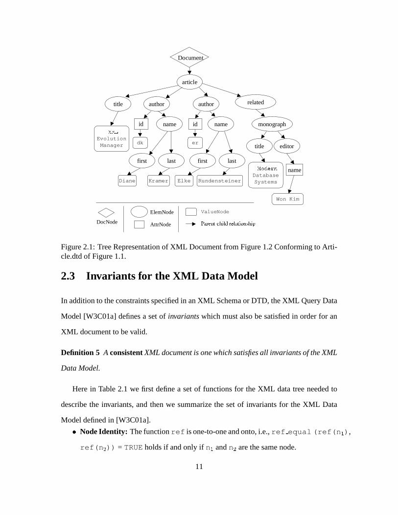
Figure 2.1: Tree Representation of XML Document from Figure 1.2 Conforming to Arti-cle.dtd of Figure 1.1.
2.3 Invariants for the XML Data Model
In addition to the constraints specified in an XML Schema or DTD, the XML Query Data
Model [W3C01a] defines a set of invariants which must also be satisfied in order for an
XML document to be valid.
Definition 5 A consistent XML document is one which satisfies all invariants of the XML
Data Model.
Here in Table 2.1 we first define a set of functions for the XML data tree needed to
describe the invariants, and then we summarize the set of invariants for the XML Data
Model defined in [W3C01a].) Node Identity: The function ref is one-to-one and onto, i.e., ref equal (ref(n * ),
ref(n + )) = TRUE holds if and only if n * and n + are the same node.
11

Function Name Mapping Descriptionref(n) N � N Reference to a node n which uniquely identi-
fies the noderef equal(n � ,n � ) N,N � Boolean Boolean function which returns TRUE only if
n � and n � are the same nodeparent(n) N � N Inverse of children function, returns the
parent of the node nattributes(n) N ��� Specialized children function which returns
only those children of type AttrNode
Table 2.1: Functions Used to Define Invariants
) Unique Parent: The parent accessor, parent(n), is a many-to-one function, i.e.,
a node has exactly one parent but many nodes may share one parent.
) Parent-child Relationships: Given two ElemNode references ref(p) and ref(n),
ref equal(parent(n),ref(p)) = TRUE holds if and only if ref(n) is
in children(p). Similarly, given a DocNode reference ref(d) and a node
reference ref(n), ref equal(parent(n),ref(d)) = TRUE holds if and
only if ref(n) is in children(d). Finally, given a AttrNode reference
ref(a) and a node reference ref(n), ref equal(parent(a),ref(n))
= TRUE holds if and only if ref(a) is in attributes(n).
) Duplicate-free list of Children: Given a node n and any two node references r *
and r + at distinct positions in the sequence children(n), ref equal (r * ,
r + ) = FALSE must hold, i.e., the ordered list of children nodes is duplicate free.
2.4 The DTD Data Model
In order to enforce constraints on XML elements and attributes and on the structure char-
acterizing how instance elements in an XML document relate to each other, we assume
that all XML documents have an associated DTD [W3C00]. A DTD allows properties or
constraints to be defined on XML elements and attributes. In order to distinguish an ele-
12

ment specification in a DTD from an element instance in an XML document, we use the
term “element definition” to refer to a DTD element, as opposed to “element instance”
in an XML document. Similarly, “attribute definition” refers to a DTD attribute spec-
ification, as opposed to “attribute instance” in an XML document. In a DTD, element
definitions indicate the tag names to be used in a conforming XML document. Element
definitions can in turn contain subelement definitions or attribute definitions or be empty.
The structure of an element definition is defined via a content-model built out of op-
erators applied to its content particles. Content particles are either simple subelement
definitions or groups of subelement definitions. Groups may be sequences indicated by
“,”, such as (a,b) or choices indicated by “ - ”, such as (a - b). For every content particle, the
content-model can specify its occurrence in its parent content particle using regular ex-
pression operators such as� ��� ���
. The semantics of these operators are defined below in
the description of the Quantifier node. Particular cases of the content-model have the fol-
lowing names: EMPTY for an element with no content particles; PCDATA for an element
that can contain only text; COMPLEX for an element that contains children subelements;
and ANY for an element that can contain any of the above content particles. When the ele-
ment can contain content particles together with text, the content-model is called MIXED
for mixed content.
A DTD can be modeled as a directed ordered graph with nodes and edges. The direc-
tion of an edge is from a parent node to a sequence of zero or more children. We use the
following notation to describe our model of a DTD graph.
Definition 6 A DTD graph � is a three-tuple � � ��� ����� ������ �!�������)� �!���, where
�is the set
of nodes in the graph,�� ���� ��!�
is the edge function which returns an ordered sequence of
direct descendent nodes,�� ���� ��!� " � % '
, where'
is a sequence of�
; and���)� �!�
is
the labeling function representing a node’s properties, such as its name,���)����� "$� % �
,
where�
is the set of properties a node can take on.
13

In addition to the children function above which returns a sequence of nodes, we
define another edge function to return a single node. childAt(pNode,pos) returns
the single child node in the children sequence of the parent node pNode at position pos,
childAt : (N, pos)%
N.
Since a node’s label represents a set of properties, the unqualified labeling function
returns a set of key-value pairs which could be iterated over to access the various proper-
ties and their corresponding values. To refer to a specific property, we use a qualification
on the label function. For example, we use the qualified notation label(/).Name to
denote the Name property (key) of node/
, where this function returns/
’s name (value).
Each node/ � N is guaranteed to contain an identity as one of its properties. The set
of possible identities includes ElemDef, AttrDef, GroupDef, Quantifier, Root, and Prim-
itive data type nodes. We group these identities into three high-level categories below,
and indicate which properties (in addition to the identity) are available from the labeling
function for that node.
1. Tag nodes:
(a) ElemDef: Each element definition node e represents an element type. label(e)= �
� � ��� ������� �� where
� � ���is the unique tag name for element definition e,
and����� �
is the content type, such as EMPTY, COMPLEX, ANY, PCDATA
or MIXED.
(b) AttrDef: Each attribute definition node a represents an attribute type. label(a)= �
� � ��� ������� � � ����� ����� � � ������ ���� where
� � ���is attribute a’s name,
����� �
is a’s content type, i.e., CDATA, ID, IDREF, IDREFS, ENUMERATION etc.,� ��� ����� �
is a’s default type, e.g., #REQUIRED, #IMPLIED or #FIXED, and� ���� ���
is a’s default value, if any.
2. Constraint nodes:
14

(a) GroupDef: Each group definition node g contains a group of children content
particles. label(g)= � ����� �� , where
����� �indicates how g’s direct chil-
dren are grouped together, that is, by sequence (i.e., label(g).Type= �
� ���� ) or by choice (i.e., label(g).Type= � � - � � ).
(b) Quantifier node: Each quantifier node q has only one child. The node q
indicates how many times that child can occur in its parent, that is, the parent
of the node q. label(q)= � ����� �� , where
����� �can be *, + or ?, with the
following semantics:
i. label(q).Type= � � ���� : child is repeatable but not required
ii. label(q).Type= � � ���� : child is repeatable and required
iii. label(q).Type= � � � �� : child is neither repeatable nor required
The set of nodes with identities including ElemDef nodes, GroupDef nodes and
Quantifer nodes are all called content particle nodes. In a DTD, the absence of a
quantifier means the content particle must appear exactly once. Correspondingly
in the DTD graph, the absence of a quantifier node between two non-quantified
content particle nodes means the child node must appear exactly once in the parent.
3. Built-in nodes:
(a) Root node: The dtdRtNode node is the entry for the DTD graph. All the
nodes in a DTD graph can be reached by traversing the graph starting from
this node. A dtdRtNode node has no label properties other than its identity.
(b) Primitive data type node: A PCDATA node p represents a textual value.
label(p)= � � �������� . The parent of a PCDATA node must be an element
definition node, indicating a content type of ANY, PCDATA or MIXED.
Figure 2.2 illustrates a DTD graph representing the Article.dtd document of Figure
1.1.
15

article
related-work
title
author
firstname
name
lastname
monograph
dtdRtNode
,
+ ?
#PCDATA
editor
*
name
,
title
,
built-in data node element node
virtual element
attribute node
parent/child relationship
constraint node
idId
REQUIRED
CDATA
IMPLIED
Figure 2.2: Graph Representation of Article.dtd of Figure 1.1
2.5 Relationships Between DTD Graphs and XML Data
Trees
An XML data tree is related to the DTD graph of the DTD to which the XML data
conforms by the URI in the DocNode of the XML tree. The function related(�
)
= � defines this relationship where�
is the DTD graph and � is the set of XML data
trees which correspond to that graph�
. Each element and attribute node in the XML tree
corresponds to a definition for that element/attribute in the DTD graph. In order to ensure
that the XML data does not violate any constraints indicated in the corresponding DTD,
when operating on an element or attribute instance in the XML data, we need a way to
refer back to the definition of the corresponding content particle in the DTD. In this sense,
16

the DTD content particle definition provides typing information which is needed during
transformation of the XML data. Similarly, when operating on an element or attribute
definition in the DTD, we need a way to refer to the corresponding data instances in the
XML tree(s). We therefore define two relationships between the XML data tree nodes
and the DTD graph nodes for this purpose.
First, to find the node in the DTD graph�
which contains the DTD definition for
a data node instance in the XML tree, we define the function typeOf(dataN)=def,
which provides a mapping from a node in an XML data tree� � � to a node in the
DTD graph�
, typeOf :� � % � �
, where� �
is the set of nodes in the XML tree�
, and� �
is the set of nodes in the DTD graph�
. Here dataN denotes the data
node instance in the XML tree, and def refers to the corresponding DTD type definition.
dataN can either be an element or attribute data node instance in�
. In the former
case, def is an element type definition in�
, while in the latter case, def denotes the
corresponding attribute type definition in�
. The function typeOf is undefined for other
types of nodes in the XML tree. In Section 2.2 where we discuss our XML data model, we
define both ElemNodes and AttrNodes as containing a reference to the node’s type.
This provides the mechanism by which we can retrieve the DTD definition for a given
data node instance.
Second, to find all data node instances which correspond to a given DTD definition,
we define the function ext(def)=dataNodes, which provides the reverse mapping:
from a node in the DTD graph�
to a set of nodes in the XML data tree(s), ext :� � %
� �, where
� �is the set of nodes in the DTD graph
�and
� �is the set of nodes
in the XML data tree�
. Here def denotes a type definition in the DTD graph�
, and
dataNodes is the set of all instance nodes in the XML data tree�
(with� � � ) of
type def. As above, def may denote either an element or an attribute type definition in
the DTD graph�
. In the former case, dataNodes is the set of all element data instance
17
nodes in the XML data tree�
corresponding to that element type, whereas in the latter
case, dataNodes is the set of all data attribute nodes in�
which correspond to the
DTD attribute definition. The function ext is undefined for other types of nodes in the
DTD graph. Again, the reference to the node’s type in the XML data tree(s) provides the
mechanism for this mapping.
18
Chapter 3
Taxonomy and Semantics of Evolution
Primitives
3.1 Introduction
In this section we present our proposed taxonomy of evolution primitives and define their
semantics. The primitives fall into two categories: those pertaining to the DTD, and those
pertaining to the XML data. Since our primitive operations are intended to manage evolu-
tion of DTDs and XML data, we do not provide explicit operations to create a new DTD
graph or XML data tree. Rather, we assume that the management system is initialized
with a valid XML document (or a set of them), from which we find and load the asso-
ciated DTD. The DTD graph is thus created during system initialization as is the initial
XML data tree (or trees). Our evolution primitives then operate on that loaded data. In
particular, the DTD primitives operate on the DTD graph, while the XML data primi-
tives operate on the XML data trees. Our goal is to provide a set of primitives with the
following characteristics:
19
) Complete: While we aim for a minimal set of primitives, at the very least all
valid changes to manipulate DTDs and XML data can be specified by one or by a
sequence of our primitives.
) Sound: Every primitive is guaranteed to maintain system integrity in terms of well-
formedness of both DTD and XML data, and validity in terms of consistency be-
tween DTD and XML data. We ensure that the execution of primitives violates
neither the invariants nor the constraints in the content model.
We list our complete taxonomy of primitives for DTD and XML data changes in Table
3.1. We then give a more detailed explanation of the primitives and provide examples of
their use.
DTD Operation DescriptioncreateDTDElement(e, t) Create element with name e and content type tdestroyDTDElement(e) Destroy element with name einsertDTDElement(E,i,q,d) Add element E at position i to parent element with quantifier q
and default value dremoveDTDElement(E,i) Remove sub-element at position i in parent EchangeQuant(E,i,q,d) Change quantifier of element E at position i in parent to quanti-
fier q with default value dconvertToGroup(start,end,gt) Group sub-elements from position start to position end in parent
into a group of type gtflattenGroup(i) Flatten group at position i in parent element, converting children
to simple sub-elementschangeGroupQuant(i,q) Change quantifier of group at position i in parent element to qaddDTDAttr(a,at,dt,dv) Add attribute with name a to parent element with type at, default
type dt, and default value dvdestroyDTDAttr(a) Destroy attribute with name a from parent element
XML Data Operation DescriptionaddDataAttr(a, av) Add an attribute with name a and value av to parentdestroyDataAttr(a) Destroy attribute with name aaddDataElement(de, i) Add element de at position idestroyDataElement(de, i) Destroy element de at position i
Table 3.1: Taxonomy of DTD and XML Data Change Primitives
20

3.2 Notation Conventions
Since the DTD and XML data models are similar, we require some notation conventions
to distinguish between various aspects of the model under consideration. In the back-
ground section in Chapter 2, in keeping with current trends in the literature, the data
model for an XML tree uses the term nodes, while in descriptions of the DTD graph it
is natural to refer to parts of the graph using the term nodes as well. To avoid confusion
here, we continue to refer to nodes in the DTD graph as nodes, while we use the term
vertices to refer to nodes in the XML data trees. We provide Table 3.2 as a guide to the
notation used in the remainder of this chapter.
Notation DescriptionG Generic DTD graphN Set of nodes in DTD graphn � N Single node in DTD graphchildren(n) = C Function returning ordered sequence of children of node n in DTD graphchildAt(n,pos) = c Function returning single child of node n in DTD graph at position posnumCh(n) = i Function returning number (i) of children of node n in DTD graphlabel(n) Function returning set of key-value pairs of node n in DTD graphdtdRtNode Root node of DTD graphe DTD Element name (string) used as function parameterE Node in DTD graph referring to an Element definitiona DTD Attribute name (string) used as function parameterA Node in DTD graph referring to an Attribute definitionGrp Node in DTD graph referring to a Group definition
�= related(G) Set of XML data trees corresponding to DTD graph G
T Single instance of XML treeV Set of vertices in XML treev � V Single vertex in XML treechildren(v) = C Function returning ordered sequence of children of vertex v in XML treechildAt(v,pos) = c Function returning single child of vertex v at position posnumCh(v) = i Function returning number (i) of children of vertex v in XML treelabel(v) Function returning label of vertex v in XML treeDE = ext(E) Set of element vertices corresponding to DTD element definition EDA = ext(A) Set of attribute vertices corresponding to DTD attribute definition Ade Single vertex corresponding to instance of data elementda Single vertex corresponding to instance of data attribute
Table 3.2: Notation Conventions used in Taxonomy of Primitives
21

While we distinguish between nodes in a DTD graph and vertices in an XML data tree,
the functions applicable to the various data types have the same names. For example, we
use children, childAt and label, both in terms of nodes in the DTD graph and vertices in
the XML trees. The reasoning behind this is that the functionality for these operations
is the same. In both cases, the children function returns an ordered sequence of either
nodes or vertices. The childAt function returns either a single node or a single vertex.
And the label function returns properties which can be used to identify the node or vertex.
We assume that there will be no confusion here, as the meaning of the particular function
should be clear within the context in which it is used.
We use standard set notation for items in a set, such as nodes in the DTD graph and
vertices in the XML tree. We introduce here notation needed for the ordered sequences of
children. We use angled brackets “ � � ” to denote a sequence, and we apply the following
operations to sequences:
) “ � C � + n” means add item n to the end of sequence C. Assume p is the parent
node (or vertex) containing the children sequence C. We use the function numCh(p)
= i to determine the number of current children of p in the sequence C, and then we
add n to position i+1.
) “ � C � + (n, pos)” means add item n at position pos to sequence C. All other items
in the sequence C in positions greater than pos will have their positions incremented
by one.
) “ � C � - n” means remove the first occurrence of item n from wherever it is found
in sequence C. We iterate over the items in the sequence C until we find n, and then
remove only that occurrence of n from C. If any other items remain in the sequence
in positions after n, those items will each have their positions decremented by one.
) “ � C � - (n, pos)” means remove item n at position pos from the sequence C. All
22

other items in the sequence C in positions greater than pos will have their positions
decremented by one.
) “ � C � + ( � N � ,pos)” means insert each item in the sequence N into the sequence
C, starting at position pos. For each n in the sequence N, this operation functions
the same as “ � C � + (n,pos+i)”, where i starts at zero for the first n and increments
for each additional item n in the sequence N.
) “ � C � - � N � ” means remove each item in the sequence N from the sequence C.
For each n in the sequence N, this operation functions the same as “ � C � - n”.
These operations may be applied sequentially to the same sequence, where the prece-
dence is from left to right, i.e., “ � C � - n * + n + ” means we first remove n * from � C �
producing � C * � as an intermediate result. Then we insert n + into � C * � , producing
� C + � as the end result. Finally, we use standard set notation on sequences only to de-
termine membership, i.e., “n � � C � ” means that the item n exists as a member of the
sequence C at some position at least once, and “n�� � C � ” means the item n does not
exist at all as a member of the sequence C.
3.3 Details of Change Primitives
In this section, we define the precise syntax and semantics of each DTD and XML change
primitive. We assume that the input DTD graph G * and input XML data trees � * are well-
formed, valid and consistent to begin with. To ensure that the targeted output DTD graph
G + and XML data trees � + remain well-formed, valid and consistent after the applica-
tion of our primitive operations, pre- and post-conditions are enforced on each change
primitive. This means that the primitive will not be executed unless the corresponding
pre-conditions are satisfied, and changes will not be committed unless the corresponding
23

post-conditions are accomplished. Post-conditions are given in the descriptions below in
terms of resulting DTD and XML data changes that are necessary in order to maintain
system integrity for the given change operation.
In the following descriptions, change primitives are applied to the input DTD graph
G * = (N * , children * , label * ) and produce the DTD graph G + = (N + , children + , label + )
as output. When a DTD change requires some change to the XML data, we apply the
changes to the set of XML data trees � = related(G), which correspond to the DTD
graph G using the related function defined in Section 2.5. For the XML data trees,
change primitives are applied to the input set of XML trees � * , where each tree in the set
T * � � � * = (V * � , children * � , label * � ) and produce a new set of XML trees � + , with T + � � � +
= (V + � , children + � , label + � ) as output.
3.3.1 Changes to the Document Definition
Primitive 1: createDTDElement
Syntax: G.createDTDElement(String e, ElemType t)
Semantics: Create a new DTD element definition node named�
with content type
for
the DTD graph�
.
Preconditions: No existing element definition node with name�
has been defined in the
DTD graph�
, i.e.,� / � �
*� ��� � ���
*� / ��� � ����� �� �
. ElemType
must be either����� ��
or�� � � � �
.
Resulting DTD Changes: A new DTD element definition node�
with name�
will
be created with content type, and will be added to the end of the sequence of chil-
dren of the root node. We get a graph�
+� � �
+� ��� ��� � � /
+� ����� ���
+�
where�
+�
�*�� �
,��� ��� � � /
+� � ��� ��� ��� �
=��� ��� � � /
*� � ��� ��� ��� �
+�
,��� � ���
+� � ��� � � ��� � �
,
and����� ���
+� � ��� ��� � � �
.� / � �
*�� � ��� ��� ��� � ��� ��� � � /+� /�� ����� ��� � � /
*� / �
, and��� � �
* ,����� ���
+� � � � ���������
*� � �
.
24

Resulting Data Changes: Since this primitive only creates a top-level DTD element
definition node, and the element is not (yet) a subelement of any other element, we call
this a “dangling” top-level element. At this point instances of�
cannot exist in the data,
i.e.,� � � � � ���
, until it is assigned as a child subelement to some other element in the
DTD graph. Therefore, this primitive causes no changes to the XML data, that is, � + =
� * .
Example 1 We add a DTD element definition to represent the concept of an author’s
middle initial as follows:
document.createDTDElement("middle", EMPTY);
Execution of this primitive operation has the effect of adding a new dangling top-level
element definition for the middle initial, as shown in Figure 3.1 on the Article DTD of
Figure 1.1.
����������� �������������������������� �!"��#�$"��%��&�"��"�����'�()+* �,�-����� ��������������� ����������&�!"��#$���%��&����"����"'�()+*����������� ��.���&�����/�10�234�5�� 5,)+* �,�-����� ��.���&�����/�10�2�3"4�5�� 56) *����������� ����!"��#$��7��8��+9���) * �,�-����� ����!"��#$��7��8� 9���) *
�,�:5��"�"��;"<"����!���#$��=�'>;&4>0&?���@A�; ?���4* �,�:5����"��;"<"����!���#$��=�'>; 4B0&?��"@"A�; ?��"4�*����������� ��.8��+9����-C�"��D �E�&�"��D �F)+* �,�-����� ��.8��+9����-C�"�D&�E�&�"�D&�F)+*����������� ��GC"���D �H�10�234�5�� 5,)+* �,�-����� ��GC"���D �H�10�2�3"4�5�� 56) *����������� ��=�"�D&�/��0&23"4&5��+5,) * �,�-����� ��=�"�D&�/��0&234�5��+5,)+*����������� ����"��"�����'�� 9�$8$"I�"�&J#F)�K�* L�M�NON�P�NQ�RTS�U�V�VWXYN�P�Z�R[�\����������� ��]9�$�8�$I��� J�#/�������������+��'��&��$"��) * �,�-����� ����"��"�����'�� 9�$8$"I����&J#F)&K*����������� ��Y��'���$��.���2�^* �,�-����� ��]9�$�8�$I��� J�#/������������+��'����$"��)+*
�,�:5��"�"��;"<"�Y�"'����$��.8��+9���3"4&5�� 5_0�;+��2���; ��4�* �,�-����� ��Y��'���$��.��2��^*�,�:5����"��;"<"�Y�"'����$��.8��+9���3"4&5��+5`0�;+�2��; ��4*
a ��b�c"?�� 5�b���"?
Figure 3.1: Results of createDTDElement Primitive Operation
Primitive 2: destroyDTDElement
Syntax: G.destroyDTDElement(String e)
Semantics: Destroy the element definition node named�
from the DTD graph�
.
Preconditions: An element definition node named�
must exist in the DTD graph�
:d � � �
* such that� ��� ���
*� � ��� � ����� � �
. The element definition node�
named�
in�
must be a non-nested element node whose content model is either EMPTY or composed
of only PCDATA, i.e.,����� ���
*� � ��� ��� � � � ����� ��
or����� ���
*� � ��� ��� � � ���� � ��� �
.
25

The element definition node�
must also be a “top-level” element, meaning it cannot exist
as a child of any node other than the root:� / � �
* -� � � � � ���
,� �� ��� ��� � � /
*� / �
.
Resulting DTD Changes: The element definition node�
with name�
will be removed
from the root node of the DTD graph�
. We get a graph�
+ = (�
+ ,��� ��� � � /
+ ,����� ���
+ )
where�
+ =�
* -�
,��� ��� � � /
+ (� ��� ��� ���
) =��� ��� � � /
* (� � � � � ���
) -�
, and� / � �
*
-� � � � � ���
,��� ��� � � /
+� / �
=��� ��� � � /
*� / �
.��� � �
* -�
,����� ���
+� � �
=���������
*� � �
.
Resulting Data Changes: In order for the preconditions above to be satisfied, there must
be no instances of element�
in the XML data trees, i.e.,� � � � ��� �
. Since�
cannot
exist in the DTD graph�
as a child of any node other than the root, there are only two
possibilities for the relationship between�
in the DTD graph and instances of�
in the
XML data trees � . First, the element definition node�
in�
could correspond to the
only child of the top-level DocNode in the XML trees � * . In our running example,�
would correspond to the article node in Figure 2.2, and instances of�
in the XML data
trees would correspond to the single child of the DocNode as shown in Figure 2.1. In
this case destroying the element definition node�
would cause the DTD graph G to be
empty, triggering the removal of all corresponding XML data trees for that graph, i.e., � +
=�. Second, the element definition node
�could be a “dangling” top-level element in
the DTD graph other than the one corresponding to the single child of the DocNode. In
this case, since it is not a child subelement of any other node, instances of�
cannot exist
in the data. Therefore this primitive would cause no changes to the XML data, that is, � +
= � * .
Example 2 We destroy the dangling top-level element definition representing the concept
of an author’s middle initial, which was created above in Example 1 as follows:
document.destroyDTDElement("middle");
Execution of this primitive operations has the effect of restoring the Article DTD of Ex-
ample 1 to the original form of Figure 1.1.
26

����������� �������������������������� �!"��#�$"��%��&�"��"�����'�()+* �,�-����� ��������������� ����������&�!"��#$���%��&����"����"'�()+*����������� ��.���&�����/�10�234�5�� 5,)+* �,�-����� ��.���&�����/�10�2�3"4�5�� 56) *����������� ����!"��#$��7��8��+9���) * �,�-����� ����!"��#$��7��8� 9���) *
�,�:5��"�"��;"<"����!���#$��=�'>;&4>0&?���@A�; ?���4* �,�:5����"��;"<"����!���#$��=�'>; 4B0&?��"@"A�; ?��"4�*����������� ��.8��+9����-C�"��D �E�&�"��D �F)+* �,�-����� ��.8��+9����-C�"�D&�E�&�"�D&�F)+*����������� ��GC"���D �H�10�234�5�� 5,)+* �,�-����� ��GC"���D �H�10�2�3"4�5�� 56) *����������� ��=�"�D&�/��0&23"4&5��+5,) * �,�-����� ��=�"�D&�/��0&234�5��+5,)+*L M1NON�P�N�Q�RTS�U�V�VWX � N�P�Z�R�[��&\ �,�-����� ����"��"�����'�� 9�$8$"I����&J#F)&K*����������� ����"��"�����'�� 9�$8$"I�"�&J#F)�K�* �,�-����� ��]9�$�8�$I��� J�#/������������+��'����$"��)+*����������� ��]9�$�8�$I��� J�#/�������������+��'��&��$"��) * �,�-����� ��Y��'���$��.��2��^*����������� ��Y��'���$��.���2�^* �,�:5����"��;"<"�Y�"'����$��.8��+9���3"4&5��+5`0�;+�2��; ��4*
�,�:5��"�"��;"<"�Y�"'����$��.8��+9���3"4&5�� 5_0�;+��2���; ��4�*a ��b�c"?�� 5�b���"?
Figure 3.2: Results of destroyDTDElement Primitive Operation
3.3.2 Changes to an Element Type Definition
Primitive 3: insertDTDElement
Syntax: p.insertDTDElement(Elem E, int pos, QuantType q,
String d)
Semantics: Insert the element definition node�
into the children sequence of the parent
node�
at position� ���
, with quantifier � , and default value�.
Preconditions: An element definition node�
must already exist in the DTD graph�
which contains the parent node�
:d � � �
* . The quantifier � must have one of the
following values: , STAR - PLUS - QMARK - NONE . . See Section 2.4 for the definitions
of these constraint values. If the quantifier � signifies a required constraint and�
is a
PCDATA element, i.e.,���������
*� � ��� ��� � � � �� � � � �
, then the default value�
must not
be null.
Resulting DTD Changes: An existing element definition node�
will be added to the
children sequence of the parent element node�
at position� ���
. We get a graph�
+ =� �
+ ,��� ��� � � /
+ ,� ��� ���
+�
where�
+� �
* , and��� ��� � � /
+� � �
=��� ��� � � /
*� � � ��� � � � ��� �
.� / � �
* � �,��� ��� � � /
+� /�� ����� ��� � � /
*� /��
, and��� � �
* ,��� � ���
+� � � � � ��� ���
*� � �
.
Resulting Data Changes: If � signifies a required constraint� ���������
*����� � � � � � , STAR,
NONE . ), then a new data element vertex���
will be created with default value�
for each
instance of the parent element definition node�
. We find the extent of the parent node�
,
27

� � � � � � � � , and then for each vertex� � � � �
, we add a new vertex���
to the children
sequence of� �
at position� ���
. We find the set of input XML data trees corresponding to
the DTD graph G using � * = related(�
). For each�
* � � � * , we get a new tree�
+ � =
(�
+ � , ��� ��� � � / + � , ����� ��� + � ) where�
+ � � �* � � ��� , and
���������+ � � � � � �
ElemNode. For each
parent vertex� � � � �
,��� ��� � � /
+ � � � � � =��� ��� � � /
* � � � � � +� ��� � � ��� �
.� � � �
* � � � �,
��� ��� � � /+ � � � � =
��� ��� � � /* � � � � , and
��� � �* � , ��������� + � � � �
=� ��� ���
* � � � �.
Example 3 First we create the middle initial element, as was done above in Example 1,
except this time we use type PCDATA, rather than EMPTY.
document.createDTDElement("middle", PCDATA);
We then use the insertDTDElement operation to insert the middle initial element into the
parent name element.
name.insertDTDElement("middle", 1, QMARK, null);
Since a middle initial is not normally required, we pass QMARK as the quantifier value
which represents an optional constraint, and null for the default value. As a result,
no data changes are required for this operation. However, after these operations have
been completed, appropriate individual middle initial values could then be inserted into
the data when so desired. Execution of these operations has the effect of first creating
a new top-level element definition for the middle element, and then inserting that as a
subelement into the name parent element definition. This effect is illustrated in Figure
3.3 on the Article DTD of Figure 1.1.
28
����������� �������������������������� �!"��#�$"��%��&�"��"�����'�()+* �,�-����� ��������������� ����������&�!"��#$���%��&����"����"'�()+*����������� ��.���&�����/�10�234�5�� 5,)+* �,�-����� ��.���&�����/�10�2�3"4�5�� 56) *����������� ����!"��#$��7��8��+9���) * �,�-����� ����!"��#$��7��8� 9���) *
�,�:5��"�"��;"<"����!���#$��=�'>;&4>0&?���@A�; ?���4* �,�:5����"��;"<"����!���#$��=�'>; 4B0&?��"@"A�; ?��"4�*����������� ��.8��+9����-C�"��D �E�&�"��D �F)+* L�M�NON�P�NQ�R ��� S�X ��� U������ S�U�V�V�W�X� ��+W � � �&\����������� ��GC"���D �H�10�234�5�� 5,)+* �,�-����� ��GC"���D �H�10�2�3"4�5�� 56) *����������� ��=�"�D&�/��0&23"4&5��+5,) * �,�-����� ��=�"�D&�/��0&234�5��+5,)+*����������� ����"��"�����'�� 9�$8$"I�"�&J#F)�K�* L�M�NON�P�NQ�RTS�U�V�VWX ��� Z������R�� �&\����������� ��]9�$�8�$I��� J�#/�������������+��'��&��$"��) * �,�-����� ����"��"�����'�� 9�$8$"I����&J#F)&K*����������� ��Y��'���$��.���2�^* �,�-����� ��]9�$�8�$I��� J�#/������������+��'����$"��)+*
�,�:5��"�"��;"<"�Y�"'����$��.8��+9���3"4&5�� 5_0�;+��2���; ��4�* �,�-����� ��Y��'���$��.��2��^*�,�:5����"��;"<"�Y�"'����$��.8��+9���3"4&5��+5`0�;+�2��; ��4*
a ��b�c"?�� 5�b���"?
Figure 3.3: Results of insertDTDElement Primitive Operation
Primitive 4: removeDTDElement
Syntax: p.removeDTDElement(String e, int pos)
Semantics: Remove the element definition node�
with name�
from the children se-
quence in the parent element definition node�
at position� ���
.
Preconditions: An element definition node named�
must exist in the DTD graph G
which contains the parent definition node�
:d � � �
* such that����� ���
*� � ��� � � ��� � �
.
The parent element definition�
must contain the subelement�
in its children sequence
at position� ���
, i.e.,��� ��� � � � � � ��� � � �
. The element�
must be a non-nested element
node, meaning it may not have any children subelements of its own:��� ��� � � /
*� � � � �
.
Resulting DTD Changes: The element definition node�
is removed from position� ���
in
the children sequence of the parent node�
. We get a graph�
+� � �
+� ��� ��� � � /
+� ���������
+�
where�
+� �
* and��� ��� � � /
+� � � ����� ��� � � /
*� � � � � � � � ��� �
.� / � �
*�� � ,��� ��� � � /
+� /�� �
��� ��� � � /*� / �
, and��� � �
* ,����� ���
+� � �
=���������
*� � �
.
Resulting Data Changes: All the instance vertices of element�
,� � � � � � � �
, are
removed from instances of the parent element definition node�
. We find the extent of the
parent node�
,� � � � � � � � , and then for each vertex
� � � � �, we remove the vertex
��� � � �from the children sequence of
� �at position
� ���. For each input XML data tree
�* � � � * , we get a new tree
�+ � = (
�+ � , ��� ��� � � / + � , ����� ��� + � ) where
�+ � =
�* � � � �
. For each
parent vertex� � � � �
,��� ��� � � /
+ � � � � � =��� ��� � � /
* � � � � � -� ��� � � ��� �
.� � � �
* � � � �,
29

��� ��� � � /+ � � � � =
��� ��� � � /* � � � � , and
��� � �* � � � �
,����� ���
+ � � � �=��� � ���
* � � � �.
Example 4 To illustrate use of this primitive operation, we remove the subelement ed-
itor from the parent element monograph (the second child subelement) as follows.
monograph.removeDTDElement("editor", 2);
Execution of this primitive operation causes the editor subelement to be removed from
the parent monograph element, as illustrated in Figure 3.4 on the Article DTD of Figure
1.1 and XML data of Figure 1.2.
����������� �������������������������� �!"��#�$"��%��&�"��"�����'�()+* �,�-����� ��������������� ����������&�!"��#$���%��&����"����"'�()+*����������� ��.���&�����/�10�234�5�� 5,)+* �,�-����� ��.���&�����/�10�2�3"4�5�� 56) *����������� ����!"��#$��7��8��+9���) * �,�-����� ����!"��#$��7��8� 9���) *
�,�:5��"�"��;"<"����!���#$��=�'>;&4>0&?���@A�; ?���4* �,�:5����"��;"<"����!���#$��=�'>; 4B0&?��"@"A�; ?��"4�*����������� ��.8��+9����-C�"��D �E�&�"��D �F)+* �,�-����� ��.8��+9����-C�"�D&�E�&�"�D&�F)+*����������� ��GC"���D �H�10�234�5�� 5,)+* �,�-����� ��GC"���D �H�10�2�3"4�5�� 56) *����������� ��=�"�D&�/��0&23"4&5��+5,) * �,�-����� ��=�"�D&�/��0&234�5��+5,)+*����������� ����"��"�����'�� 9�$8$"I�"�&J#F)�K�* �,�-����� ����"��"�����'�� 9�$8$"I����&J#F)&K*L M1NON�P�N�Q�RTS � ����� � ����� � �U �W�X � X�V�U � � �&\ L�M�NON�P�NQ�RTS � ����� � ����� � �U �WX � \����������� ��Y��'���$��.���2�^* �,�-����� ��Y��'���$��.��2��^*
�,�:5��"�"��;"<"�Y�"'����$��.8��+9���3"4&5�� 5_0�;+��2���; ��4�* �,�:5����"��;"<"�Y�"'����$��.8��+9���3"4&5��+5`0�;+�2��; ��4*a ��b�c"?�� 5�b���"?
���"����"����* �������������*����������*��"���Y���$�&!����$8.����8��I���"�� ���������* �����&�����*�����Y���$���!"���"$�8.���8�"I"���� &���������*����!���#$��=�'����+'���� * �"�!"��#�$"�=�'���� '���� *
�8��+9���* ��8�� 9��*�C"���D&�*4��"�8����"C"���D&�* ��C�"�D&��*�4��"��8�����C�"�D&��*���"�D&��*����"� 9��������"�D&��* ����D ��*����� 9���"��"���D ��*
��&8� 9��* � &8��+9���*����!��"#�$"��* � ��!���#$��"*����!���#$��=�'����+����� * �"�!"��#�$"�=�'���� ���� *
�8��+9���* ��8�� 9��*�C"���D&�*�����������C�"�D&��* ��C�"�D&��*������"�� �C"���D ��*���"�D&��*�?�!"8'��8�D&�����&8��"���"��D ��* ����D ��*?"!�8'"�"8�D&����8����� "���D&�*
��&8� 9��* � &8��+9���*����!��"#�$"��* � ��!���#$��"*������"����"'* �"�"��"�����'�*
� 9�$�8�$I��� J�#* �+9�$8$"I����&J#�*�����&�����*&��$"'����8='����������D&�BD���D ��&9ED� &���&�����* ���������* ��$"'"���8G'��������D��>D���D&���&9FD��� ���������*LX�VU � � ��� S�X���� � � �"! U S#�+\"L $�X�VU � �\ � 9�$�8�$I��� J�#�*
�� 9�$8$"I�"�&J#�* � ����"����"'*����"��������'* ���"����"����*
</article> a ��b�c"?�� 5�b���"?
Figure 3.4: Results of removeDTDElement Primitive Operation
Primitive 5: changeQuant
Syntax: p.changeQuant(Elem E, int pos, QuantType q, String d)
Semantics: Change the quantifier constraint for the element definition node�
in the
children sequence of parent element node�
at position� ���
to type � , with default value�.
30
Preconditions: The element definition node�
must exist in the DTD graph G which
contains the parent definition node�
:d � � �
* . The parent element definition�
must
contain the node�
in its children sequence at position� ���
, i.e.,��� ��� � � ��� � ��� � � �
.
The QuantType � must have one of the following values: , STAR - PLUS - QMARK -NONE . . See Section 2.4 for the definitions of these constraint values. If the quantifier �
signifies a required constraint, the default value�
must not be null.
Resulting DTD Changes: There are three possibilities which will determine what changes
are required to the DTD graph G for this operation. First, if the original element defini-
tion node�
was not previously quantified and the QuantType � is not NONE, then a new
quantifier node must be created and inserted into the DTD graph. Second, if the original
element definition node�
was previously quantified and the QuantType � is NONE, then
the old quantifier node must be removed from the DTD graph. Third, if the original ele-
ment definition node�
was previously quantified and the QuantType � is not NONE, then
we simply need to change the quantifier node’s type to � . The fourth possibility would be
that original element definition node�
was not previously quantified and the QuantType
� is NONE. In this case we are not actually changing the quantifier of the node�
, so no
DTD changes would be required. We now show the resulting DTD changes for each of
the three possibilities which require changes to the DTD graph.
1. First we remove the node�
from the children sequence in the parent node�
at
position� ���
. Next we create a new quantifier node�
with type � and insert�
into the children sequence of the parent node�
at position� ���
. Finally, we insert
the node�
into the children sequence of the quantifier node�
. We get a graph�
+� � �
+� ��� ��� � � /
+� ���������
+�
where�
+� �
* � �,��� ��� � � /
+� � �
=��� ��� � � /
*� � �
- (� � � ���
) + (� � � ���
), and����� ���
+� � �
.� � � �
= � .� / � �
* � �,��� ��� � � /
+� / �#�
��� ��� � � /*� / �
, and��� � �
* ,����� ���
+� � �
=����� ���
*� � �
.
31

2. First we remove the quantifier node�
from the children sequence in the parent
node�
at position� ���
. We then find the node�
in the children sequence of the
node�
, and insert�
into the children sequence in the parent node�
at position� ���
. Finally we destroy the quantifier node�
which is no longer needed. We get
a graph�
+� � �
+� ��� ��� � � /
+� ��� � ���
+�
where�
+� �
* � �and
��� ��� � � /+� � �
=��� ��� � � /
*� � �
- (� � � ���
) + (� � � ���
).� / � �
* � �,��� ��� � � /
+� /�� � ��� ��� � � /
*� /��
,
and��� � �
* � �,���������
+� � �
=��� � ���
*� � �
.
3. In the simplest case, we need only change the quantifier node�
’s type to � in the
children sequence of the parent node�
at position� ���
. We get a graph�
+�
� �+� ��� ��� � � /
+� ���������
+�
where�
+� �
* and���������
+� � �
.����� �
= � .� / � �
* ,��� ��� � � /
+� / �
=��� ��� � � /
*� /��
, and��� � �
* � �,���������
+� � � � ��� � ���
*� � �
.
Resulting Data Changes: The XML data changes required for this primitive depend on
the old and new quantifier values. These changes can be summarized using the following
two rules:
1. If the old quantifier represented a repeatable constraint and the new quantifier does
not, we find all the instance vertices of element�
,� �
* =� � � � �
, and remove all
but the first occurrence,� �
+ =� �
* - the first� � � � �
* , from instances of the
parent element node�
. We find the extent of the parent node�
,� � � � � � � � , and
then for each vertex� � � � �
, we remove each vertex� � � � �
+ from the children
sequence of� �
. For each input XML data tree�
* � � � * , we get a new tree�
+ �
= (�
+ � , ��� ��� � � / + � , ����� ��� + � ) where�
+ � =�
* � � � �+ . For each parent vertex
� � �
� �,��� ��� � � /
+ � � � � � =��� ��� � � /
* � � � � � -� � �
+�.� � � �
* � � � �,��� ��� � � /
+ � � � � =��� ��� � � /
* � � � � , and��� � �
* � � � �+ ,� ��� ���
+ � � � �=����� ���
* � � � �.
2. If the new quantifier represents a required constraint and the old quantifier did not,
for each instance of the parent node�
which did not contain any instance of the child
32

element node�
, we must create a new instance vertex���
of element�
with default
value�
and insert� �
into instances of the parent node�
. We find the extent of the
parent node�
,� �(� � � � � � , and then for each vertex
� � � � �we first check
whether a���
exists at position� ���
. If not, then we insert���
into� �
at position� ���
.
Let� �
be this set of newly created and inserted instances of� �
. For each input
XML data tree�
* � � � * , we get a new tree�
+ � = (�
+ � , ��� ��� � � / + � , ��������� + � ) where�
+ � =�
* � � � �. For each vertex
� � � � �,����� ���
+ � � ��� � �ElemNode, and for each
parent vertex� � � � �
,��� ��� � � /
+ � � � � � =��� ��� � � /
* � � � � � +� � � � � ��� �
, wherever���
did not exist at position� ���
before.� � � �
* � � � �,��� ��� � � /
+ � � � � =��� ��� � � /
* � � � � ,and
��� � �* � � � �
,���������
+ � � � �=� ��� ���
* � � � � .
The remaining combinations of old and new quantifiers such as not repeatable becomes
repeatable, or required becomes not required, cause no changes to the XML data.
Example 5 We change the author subelement’s quantifier in the parent article el-
ement from repeatable (PLUS) to a non-repeatable constraint (NONE) as follows:
article.changeQuant(author, 2, NONE, null);
Execution of this primitive operation, in addition to changing the quantifier in the DTD
element definition, also causes the removal of multiple author elements found in the
data (all but the first occurrence are removed). The effect on the Article DTD, the first
line of which is all that changes, of Figure 1.1 and XML data of Figure 1.2 is illustrated
in Figure 3.5.
33
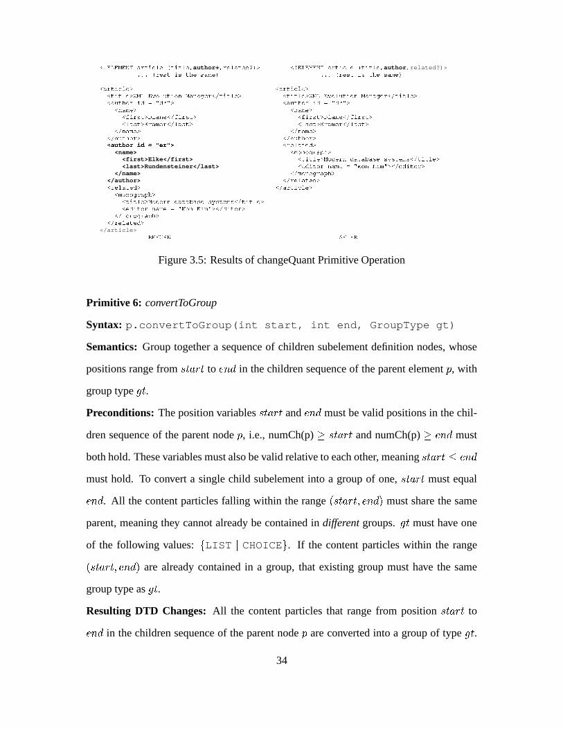
����������� �������������������������� author+ �&�"��"�����'�()+* �,�-����� ��������������� ���������� author,related?)>����� �1�"��D&�>�DT��#��>D� 9��E) ����� �1���D&�>��D �"#�>D�+9���)
���"����"����* �������������*����������*��"���Y���$�&!����$8.����8��I���"�� ���������* �����&�����*�����Y���$���!"���"$�8.���8�"I"���� &���������*����!���#$��=�'����+'���� * �"�!"��#�$"�=�'���� '���� *
�8��+9���* ��8�� 9��*�C"���D&�*4��"�8����"C"���D&�* ��C�"�D&��*�4��"��8�����C�"�D&��*���"�D&��*����"� 9��������"�D&��* ����D ��*����� 9���"��"���D ��*
��&8� 9��* � &8��+9���*����!��"#�$"��* � ��!���#$��"*L ��� � � �=UV ��� X ��� \ �"�"��"�����'�*<name> �+9�$8$"I����&J#�*<first>Elke</first> ���������* ��$"'"���8G'��������D��>D���D&���&9FD��� ���������*<last>Rundensteiner</last> �"�"'��&��$��.8��+9���������$8"��� 9#� *"��&��'��&��$"��*
</name> � 9�$�8�$I��� J�#�*</author> � ����"����"'*������"����"'* ���"����"����*
� 9�$�8�$I��� J�#*�����&�����*&��$"'����8='����������D&�BD���D ��&9ED� &���&�����*���'����$"�.8�� 9��"������$8"���+9#�+*�� �'��&��$"��*
�� 9�$8$"I�"�&J#�*����"��������'*
</article> a ��b�c"?�� 5�b���"?
Figure 3.5: Results of changeQuant Primitive Operation
Primitive 6: convertToGroup
Syntax: p.convertToGroup(int start, int end, GroupType gt)
Semantics: Group together a sequence of children subelement definition nodes, whose
positions range from� � ��
to� / �
in the children sequence of the parent element�
, with
group type�
.
Preconditions: The position variables� � ��
and� / �
must be valid positions in the chil-
dren sequence of the parent node�
, i.e., numCh(p)� � � ��
and numCh(p)� � / �
must
both hold. These variables must also be valid relative to each other, meaning� � �� � / �
must hold. To convert a single child subelement into a group of one,� � ��
must equal� / �
. All the content particles falling within the range� � � �� � � / � �
must share the same
parent, meaning they cannot already be contained in different groups.�
must have one
of the following values: , LIST - CHOICE . . If the content particles within the range� � � �� � � / � �
are already contained in a group, that existing group must have the same
group type as�
.
Resulting DTD Changes: All the content particles that range from position� � ��
to� / �
in the children sequence of the parent node�
are converted into a group of type�
.
34

First we create a new group definition node� � �
. We then iterate over the children se-
quence of�
, removing children nodes within the range� � � �� � � / � �
, and inserting them
in the same order into the children sequence of� � �
. Let��
be this sequence of chil-
dren nodes. Finally, we insert� � �
into the children sequence of the parent node�
at
position� � ��
. We get a graph�
+� � �
+� ��� ��� � � /
+� ����� ���
+�
where�
+� �
* � � � �,
��� ��� � � /+� � � � ��� ��� � � /
*� � � � � �� � � � � � � ��� � �� �
and����� ���
+� � � � ��� ��� � � � �
.� / � �
* � �,��� ��� � � /
+� /�� ����� ��� � � /
*� /��
, and��� � �
* ,��� � ���
+� � �
=� ��� ���
*� � �
.
Resulting Data Changes: Since this primitive does not allow creating a nested group of
a different type from the parent group, this primitive causes no changes to the XML data,
as groups are for hierarchical organization purposes only. In a DTD element definition, a
children sequence does not change semantically when a new set of parentheses is added.
We illustrate with an example, where the following two DTD element definitions for the
parent node � have the same meaning in terms of the corresponding XML data. Thus, � +
= � * .
<!ELEMENT x (a, b, c, d, e)>
<!ELEMENT x (a, (b, c), d, e)>
The same argument holds if both the new nested group and the old parent group are of type
CHOICE, as illustrated with the following example where both DTD element definitions
have the same semantics in terms of the XML data.
<!ELEMENT x (a | b | c | d | e)>
<!ELEMENT x (a | (b | c) | d | e)>
Example 6 This operation is performed on a parent element, in order to convert a range
of its subelements into a group. To illustrate, we create a LIST group of one, for the
single author subelement in the parent article element as follows:
article.convertToGroup(2, 2, "LIST");
35

Execution of this primitive operation has the effect of converting the second subele-
ment (author) in the article parent element to a group of one. The effect on the first
line of the Article DTD of Figure 1.1 is shown in Figure 3.6. There are no other changes
to the DTD, and no data changes are required as a result of this primitive operation.
����������� �������������������������� author+ �&�"��"�����'�()+* �,�-����� ��������������� ���������� (author+),related?)>����� �1�"��D&�>�DT��#��>D� 9��E) ����� �1���D&�>��D �"#�>D�+9���)
a ��b�c"?�� 5�b���"?
Figure 3.6: Results of convertToGroup Primitive Operation
Primitive 7: flattenGroup
Syntax: p.flattenGroup(int pos)
Semantics: Convert a group of content particles at position� ���
in the children sequence
of the parent node�
into simple subelements, i.e., remove the group node containing those
subelements.
Preconditions: The content particle at position� ���
in the children sequence of the
parent node�
must be a group definition node, i.e.,� ��� ��� � ��� ��� � � ��� � ��� � ��� ��� / � � �
� � � � � �����.
Resulting DTD Changes: First the group definition node at position� ���
in the children
sequence of the parent node�
,� � � � ��� ��� � � � � � ��� �
, is removed from�
. Then all
of the content particles which were contained in the children sequence of that group,� � � ��� ��� � � / � � � � �
, become direct descendents of the parent node�
. We iterate
over the children nodes� � � � �
, inserting the first into�
at position� ���
, the second
at position� ��� � �
, the third at position� ��� ���
, and so on. We get a graph�
+ =� �
+� ��� ��� � � /
+� ��� � ���
+�
where�
+� �
*� � � �and
��� ��� � � /+� � � � ��� ��� � � /
*� � � �
� � � � � � ��� � � � � � � � ��� �.� / � �
* � �,��� ��� � � /
+� / � � ��� ��� � � /
*� /��
, and��� � �
* ,���������
+� � �
=���������
*� � �
.
Resulting Data Changes: Since group nodes are not represented in the XML data, the
36
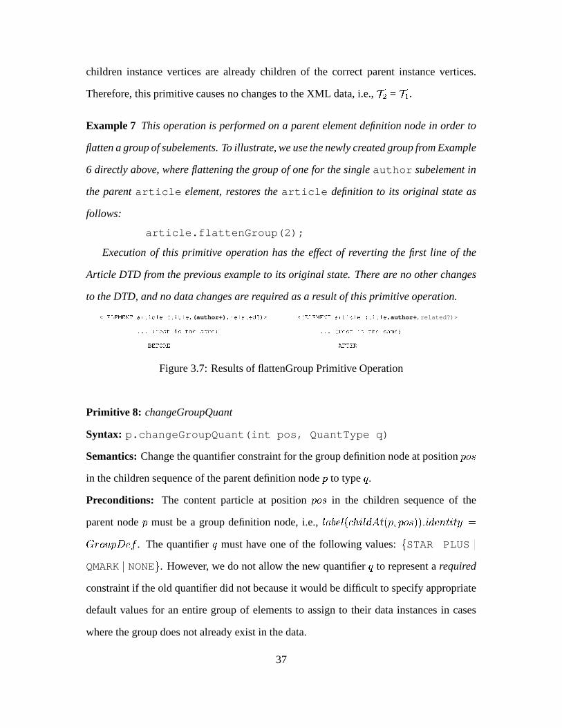
children instance vertices are already children of the correct parent instance vertices.
Therefore, this primitive causes no changes to the XML data, i.e., � + = � * .
Example 7 This operation is performed on a parent element definition node in order to
flatten a group of subelements. To illustrate, we use the newly created group from Example
6 directly above, where flattening the group of one for the single author subelement in
the parent article element, restores the article definition to its original state as
follows:
article.flattenGroup(2);
Execution of this primitive operation has the effect of reverting the first line of the
Article DTD from the previous example to its original state. There are no other changes
to the DTD, and no data changes are required as a result of this primitive operation.
����������� �������������������������� (author+) � �"��"�����'�() * ����������� ����������"����������������� author+,related?)>����� �1�"��D&�>�DT��#��>D� 9��E) ����� �1���D&�>��D �"#�>D�+9���)
a ��b�c"?�� 5�b���"?
Figure 3.7: Results of flattenGroup Primitive Operation
Primitive 8: changeGroupQuant
Syntax: p.changeGroupQuant(int pos, QuantType q)
Semantics: Change the quantifier constraint for the group definition node at position� ���
in the children sequence of the parent definition node�
to type � .
Preconditions: The content particle at position� ���
in the children sequence of the
parent node�
must be a group definition node, i.e.,� ��� ��� � ��� ��� � � ��� � ��� � ��� ��� / � � �
� � � � � �����. The quantifier � must have one of the following values: , STAR - PLUS -
QMARK - NONE . . However, we do not allow the new quantifier � to represent a required
constraint if the old quantifier did not because it would be difficult to specify appropriate
default values for an entire group of elements to assign to their data instances in cases
where the group does not already exist in the data.
37

Resulting DTD Changes: The changes we describe here are the same as those for prim-
itive 5 above, with the simple replacement of� � �
for�
, since we are now dealing with a
group definition node rather than an element definition node. There are three possibilities
which will determine what changes are required to the DTD graph G for this operation.
First, if the original group definition node� � �
was not previously quantified and the
QuantType � is not NONE, then a new quantifier node must be created and inserted into
the DTD graph. Second, if the original group definition node� � �
was previously quanti-
fied and the QuantType � is NONE, then the old quantifier node must be removed from the
DTD graph. Third, if the original group definition node� � �
was previously quantified
and the QuantType � is not NONE, then we simply need to change the quantifier node’s
type to � . The fourth possibility would be that original group definition node� � �
was
not previously quantified and the QuantType � is NONE. In this case we are not actually
changing the quantifier of the node� � �
, so no DTD changes would be required. We now
show the resulting DTD changes for each of the three possibilities which require changes
to the DTD graph.
1. First we remove the node� � �
from the children sequence in the parent node�
at
position� ���
. Next we create a new quantifier node�
with type � and insert�
into the children sequence of the parent node�
at position� ���
. Finally, we insert
the node� � �
into the children sequence of the quantifier node�
. We get a graph�
+� � �
+� ��� ��� � � /
+� ���������
+�
where�
+� �
* � �,��� ��� � � /
+� � �
=��� ��� � � /
*� � �
- (� � � � � ���
) + (� � � ���
), and� ��� ���
+� � �
.����� �
= � .� / � �
* � �,��� ��� � � /
+� / � �
��� ��� � � /*� / �
, and��� � �
* ,����� ���
+� � �
=����� ���
*� � �
.
2. First we remove the quantifier node�
from the children sequence in the parent
node�
at position� ���
. We then find the node� � �
in the children sequence of the
node�
, and insert� � �
into the children sequence in the parent node�
at position
38

� ���. Finally we destroy the quantifier node
�which is no longer needed. We get
a graph�
+� � �
+� ��� ��� � � /
+� ��� � ���
+�
where�
+� �
* � �and
��� ��� � � /+� � �
=��� ��� � � /
*� � �
- (� � � ���
) + (� � � � � ���
).� / � �
* � � ,��� ��� � � /
+� / � ����� ��� � � /
*� /��
,
and��� � �
* � �,���������
+� � �
=��� � ���
*� � �
.
3. In the simplest case, we need only change the quantifier node�
’s type to � in the
children sequence of the parent node�
at position� ���
. We get a graph�
+�
� �+� ��� ��� � � /
+� ���������
+�
where�
+� �
* and���������
+� � �
.����� �
= � .� / � �
* ,��� ��� � � /
+� / �
=��� ��� � � /
*� /��
, and��� � �
* � �,���������
+� � � � ��� � ���
*� � �
.
Resulting Data Changes: Similar to the resulting data changes for Primitive 5 above,
if the old quantifier represented a repeatable constraint and the new quantifier does not,
we find all the instance vertices of the group� � �
,� �
* =� � � � � � �
, and remove all but
the first occurrence,� �
+ =� �
* - the first� � � � �
* , from instances of the parent
node�
. We find the extent of the parent node�
,� � � � � � � � , and then for each vertex
� � � � �, we remove each vertex
� � � � �+ from the children sequence of
� �. For each
input XML data tree�
* � � � * , we get a new tree�
+ � = (�
+ � , ��� ��� � � / + � , ��������� + � ) where�
+ � =�
* � � � �+ . For each parent vertex
� � � � �,��� ��� � � /
+ � � � � � =��� ��� � � /
* � � � � � -� � �
+�.� � � �
* � � � �,��� ��� � � /
+ � � � � =��� ��� � � /
* � � � � , and��� � �
* � � � �+ ,����� ���
+ � � � �=��� � ���
* � � � �
Example 8 This operation is performed on a parent element to change the quantifier of a
group subelement node. To illustrate, we change the quantifier on the monograph group
node in the parent related element definition from repeatable but not required (“*”)
to not repeatable and not required (“?”) as follows:
related.changeGroupQuant(1, "?");
Execution of this primitive operation causes a change to the quantifier on the mono-
graph group node in the parent related element definition. Since the XML data only
39

contains a single instance of the monograph content particle, no data changes are re-
quired as a result of this primitive. The effect on the Article DTD of Figure 1.1 is shown
in Figure 3.8.
����������� �������������������������� �!"��#�$"��%��&�"��"�����'�()+* �,�-����� ��������������� ����������&�!"��#$���%��&����"����"'�()+*����������� ��.���&�����/�10�234�5�� 5,)+* �,�-����� ��.���&�����/�10�2�3"4�5�� 56) *����������� ����!"��#$��7��8��+9���) * �,�-����� ����!"��#$��7��8� 9���) *
�,�:5��"�"��;"<"����!���#$��=�'>;&4>0&?���@A�; ?���4* �,�:5����"��;"<"����!���#$��=�'>; 4B0&?��"@"A�; ?��"4�*����������� ��.8��+9����-C�"��D �E�&�"��D �F)+* �,�-����� ��.8��+9����-C�"�D&�E�&�"�D&�F)+*����������� ��GC"���D �H�10�234�5�� 5,)+* �,�-����� ��GC"���D �H�10�2�3"4�5�� 56) *����������� ��=�"�D&�/��0&23"4&5��+5,) * �,�-����� ��=�"�D&�/��0&234�5��+5,)+*L M1NON�P�N�Q�R �"XW � X�V � S � � ��� � ��� � � � \ L�M�NON�P�NQ�R �"XW � X�V � S � � ��� � ��� � � �\����������� ��]9�$�8�$I��� J�#/�������������+��'��&��$"��) * �,�-����� ��]9�$�8�$I��� J�#/������������+��'����$"��)+*����������� ��Y��'���$��.���2�^* �,�-����� ��Y��'���$��.��2��^*
�,�:5��"�"��;"<"�Y�"'����$��.8��+9���3"4&5�� 5_0�;+��2���; ��4�* �,�:5����"��;"<"�Y�"'����$��.8��+9���3"4&5��+5`0�;+�2��; ��4*a ��b�c"?�� 5�b���"?
Figure 3.8: Results of changeGroupQuant Primitive Operation
Primitive 9: addDTDAttr
Syntax: p.addDTDAttr(String a, AttrType at, DefType dt,
String dv)
Semantics: A new attribute definition node with name�, attribute type
� , default type
� , and default value
� � will be created and added to the children sequence of the parent
node�
.
Preconditions: No attribute with name�
has been defined in the parent element definition�
, i.e.,� / � ��� ��� � � / � � �
where��� � ��� � /���� ��� / � � � � ��� �����
,����� ��� � / ��� � � ��� �� �
.
The attribute type�
must have one of the following values: , CDATA - CHOICE - HREF -ID - IDREF - IDREFS - NMTOKEN . . The default type
� must have one of the following
values: , #REQUIRED - #IMPLIED - #FIXED - #DEFAULT . . If the default type�
is
anything other than #IMPLIED, the default value� � must not be null.
Resulting DTD Changes: A new attribute definition node�
will be created with name�,
attribute type�
, default type�
, and if� � �� �
, default value� � .
�will then be added to
the children sequence of the parent node�
. We get a graph�
+� � �
+� ��� ��� � � /
+� ���������
+�
where�
+� �
* � � ,��� ��� � � /
+� � �
=��� ��� � � /
*� � �
+�
,����� ���
+��� ��� � �����
=�,����� ���
+� � �
.����� �
40

=�
,� ��� ���
+� � ��� ����� ��� � �
=�
, and����� ���
+��� ��� ������ ���
=� � .
� / � �* � � ,
��� ��� � � /+� /��
=��� ��� � � /
*� / �
, and��� � �
* ,���������
+� � �
=��� � ���
*� � �
.
Resulting Data Changes: If the default type�
= #REQUIRED, then a new data attribute
vertex� �
will be created with default value� � for each instance of the parent element
definition node�
. We find the extent of the parent node�
,� � � � � � � � , and then for
each vertex� � � � �
, we add a new vertex���
to the children sequence of� �
. For
each input XML data tree�
* � � � * , we get a new tree�
+ � = (�
+ � , ��� ��� � � / + � , ����� ��� + � )where
�+ � =
�* � � � �
, and����� ���
+ � � ��� � �AttrNode. For each parent vertex
� � � � �,
��� ��� � � /+ � � � � � =
��� ��� � � /* � � � � � +
���.� � � �
* � � � �,��� ��� � � /
+ � � � � =��� ��� � � /
* � � � � ,and
��� � �* � , � ��� ��� + � � � �
=����� ���
* � � � �.
Example 9 This operation is performed on a parent element to add a new attribute defini-
tion. To illustrate, we add a published attribute to the article element definition to
indicate whether this article has been published or not. We pass CDATA as the attribute
type, #REQUIRED as the default type, meaning each instance of the article element
in the data must have this new attribute, and TRUE for the default value as follows:
article.addDTDAttr("published", CDATA, #REQUIRED,
TRUE);
Execution of this primitive operation causes a new line to be added after the first line of
the Article DTD of Figure 1.1, and the rest of the DTD remains the same. Since there is
only one instance of the article content particle in the data, only the first line of the
XML data from Figure 1.2 changes, as shown in Figure 3.9.
����������� �������������������������� �!"��#�$"��%��&�"��"�����'�()+* ����������� ����������"����������������� �!"��#�$"��%��&�"��"�����'�()+*����������� ��.���&�����/�10�234�5�� 5,)+* <!ATTLIST article published CDATA #REQUIRED>����������� ��.���&������10�234�5�� 5,)+*
����� �1���D �B��D �"#�>D�+9���) ����� �:�"��D �>�DT��#��BD�� 9��E)L � � �U � W�X�\ L � � �U � WX � ��� W"U�� � X�V����+R�����N � \
����������*��"���Y���$�&!����$8.����8��I���"�� ���������* �����&�����*�����Y���$���!"���"$�8.���8�"I"���� &���������*
����� �1���D �B��D �"#�>D�+9���) ����� �:�"��D �>�DT��#��BD�� 9��E)a ��b�c"?�� 5�b���"?
Figure 3.9: Results of addDTDAttr Primitive Operation
41

Primitive 10: destroyDTDAttr
Syntax: p.destroyDTDAttr(String a)
Semantics: The attribute definition node with name�
will be removed from the children
sequence in the parent node�
.
Preconditions: An attribute definition node with name�
must already exist in the chil-
dren sequence of the parent node�
, i.e.,d / � ��� ��� � � / � � �
such that� ��� ��� � /���� ��� / � � �
� ��� �����and
��� � ��� � /���� � � ���=�.
Resulting DTD Changes: The attribute definition node�
with name�
will be removed
from the children sequence of the parent node�
. We get a graph�
+� � �
+� ��� ��� � � /
+� ��� � ���
+�
where�
+� �
* � �and
��� ��� � � /+� � �
=��� ��� � � /
*� � �
-�
.� / � �
* � �,��� ��� � � /
+� /��
=��� ��� � � /
*� / �
, and��� � �
* � �,���������
+� � �
=��� � ���
*� � �
.
Resulting Data Changes: All the instance vertices of attribute�
,� � � � � ��� �
are
removed from instances of the parent element definition node�
. We find the extent of the
parent node�
,� � � � � � � � , and then for each vertex
� � � � �, we remove the vertex
��� � � �from the children sequence of
� �. For each input XML data tree
�* � � � * ,
we get a new tree�
+ � = (�
+ � , ��� ��� � � / + � , ����� ��� + � ) where�
+ � =�
* � � � �. For each parent
vertex� � � � �
,��� ��� � � /
+ � � � � � =��� ��� � � /
* � � � � � -���
.� � � �
* � � � �,��� ��� � � /
+ � � � �=��� ��� � � /
* � � � � , and��� � �
* � � � �,���������
+ � � � �=� ��� ���
* � � � �.
Example 10 This operation is performed on a parent element to remove an existing at-
tribute. To illustrate, we remove the published attribute from the article element
which was added in Example 9 above as follows:
article.destroyDTDAttr("published");
Execution of this primitive operation causes the new line which was added in the
previous example to be removed, while the rest of the DTD remains the same. Since there
is only one instance of the article content particle in the data, only the first line of the
XML data from the example above changes. The result after execution of this primitive is
42

to restore both the DTD and the XML data to its original form of Figures 1.1 and 1.2 as
shown in Figure 3.10.
����������� �������������������������� �!"��#�$"��%��&�"��"�����'�()+* ������"������ ���������"������������������ �!��"#�$"��%�� �"��"�����'�() *L�M ��R"R"O ��� R � � �U � WX � ��� W"U�� � X�V � � ��R�� � ��N���� � ��N���\ ������"������ ��.�����������0&234�5��+5,)+*
����������� ��.���&�����/�10�234�5�� 5,)+*
����� �1���D �B��D �"#�>D�+9���) ����� �:�"��D �>�DT��#��BD�� 9��E)L � � �U � W�X � ��� W�U � � X"V ��� R����N �+\ L � � �U � WX\
����������*��"���Y���$�&!����$8.����8��I���"�� ���������* �����&�����*�����Y���$���!"���"$�8.���8�"I"���� &���������*
����� �1���D �B��D �"#�>D�+9���) ����� �:�"��D �>�DT��#��BD�� 9��E)a ��b�c"?�� 5�b���"?
Figure 3.10: Results of destroyDTDAttr Primitive Operation
3.3.3 Changes to the XML Data
Primitive 11: addDataAttr
Syntax: de.addDataAttr(String a, String av)
Semantics: A data attribute instance���
will be created with name�
and value� � , and
will be added to the children sequence of the data element vertex���
.
Preconditions: An attribute definition�
for the attribute instance vertex���
must ex-
ist in the DTD graph, i.e.,d �
such that � � ��� � � ��� � � �
. If the default type of the
attribute definition node�
is required, i.e.,��������� ��� ��� ����� ��� � � �
#REQUIRED, then
this attribute must already exist in the data, so the addDataAttr primitive is not valid
for such an attribute. If the default type of the attribute definition node�
is fixed, i.e.,��������� ��� ��� ����� ��� � � �
#FIXED, then the value� � must be null since the fixed value is
already specified in the DTD attribute definition�
, and a fixed value may not be changed.
Resulting DTD Changes: This is an XML data change primitive operation. Therefore
there are no resulting changes to the DTD graph, i.e.,�
+ =�
* .
Resulting Data Changes: An instance���
of the attribute named�
will be added to the
children sequence of the data element vertex���
. If� � �� �
, the value� � will be assigned to
the data attribute vertex���
. Otherwise, if the default type of the DTD attribute definition
43

node�
is fixed, i.e.,� ��� ��� � � ��� ����� ����� � �
#FIXED, then the fixed value declared in
the attribute definition,� ��� ��� � � ��� ������ ���
will be assigned to the data attribute instance���
. For each input XML data tree�
* � � � * , we get a new tree�
+ � = (�
+ � , ��� ��� � � / + � ,���������
+ � ) where�
+ � =�
* � � � �,��� ��� � � /
+ � � � � � =��� ��� � � /
* � � ��� � +� �
, and��� � ���
+ � � ��� � =
AttrNode.� � � �
* � � ���,��� ��� � � /
+ � � � � =��� ��� � � /
* � � � � , and��� � �
* � , ��� � ��� + � � � �=
���������* � � � �
.
Example 11 To illustrate use of this primitive operation, we first add a new attribute
definition called “primary” to the author element in the DTD to indicate whether an
author is the primary author of an article or not, using #IMPLIED for the default type.
We then use the addDataAttr primitive to assign values to the two authors of the article
in the example. This operation is performed on an instance of an element in the data. To
address such an instance, we use the XPath notation, as defined in [W3C99] as follows:
�!��"#�$�� � �'�'"4�4&5����� � � J����+9��������"�]3"4&5��+56�.;+�2��; ��4��]8"!�����) ��!��"#�$���� � C��8�'"4����������� 9��8�� � � �"�����������������!��"#�$"����������) ��!��"#�$���� � �"'�'4������ 5����� � � J����+9��"�����"�T�?A�F) ��!��"#�$�� � C��8�'"4����������� 9��8�� � � �"�����������������!��"#�$"���������) ��!��"#�$�� � �"'�'4������ 5����� � � J����+9��"�����"� b�5���<��E) �
Execution of these primitive operations first causes a new line to be added to the DTD
for the primary attribute in the author element definition. Then data instances of the
attribute are added to the two author element instances in the XML data with appropri-
ate values. The effect on the Article DTD of Figure 1.1 and the XML data of Figure 1.2 is
shown in Figure 3.11.
44

����������� �������������������������� �!"��#�$"��%��&�"��"�����'�()+* �,�-����� ��������������� ����������&�!"��#$���%��&����"����"'�()+*����������� ��.���&�����/�10�234�5�� 5,)+* �,�-����� ��.���&�����/�10�2�3"4�5�� 56) *����������� ����!"��#$��7��8��+9���) * �,�-����� ����!"��#$��7��8� 9���) *
�,�:5��"�"��;"<"����!���#$��=�'>;&4>0&?���@A�; ?���4* �,�:5����"��;"<"����!���#$��=�'>; 4B0&?��"@"A�; ?��"4�*����������� ��.8��+9����-C�"��D �E�&�"��D �F)+* L�M ��R�R"O ��� R ��� � � � � ��U S � � � � � ��R�� � � P�ZO � N ��\����������� ��GC"���D �H�10�234�5�� 5,)+* �,�-����� ��.8��+9����-C�"�D&�E�&�"�D&�F)+*����������� ��=�"�D&�/��0&23"4&5��+5,) * �,�-����� ��GC"���D �H�10�2�3"4�5�� 56) *����������� ����"��"�����'�� 9�$8$"I�"�&J#F)�K�* �,�-����� ��=�"�D&�/��0&234�5��+5,)+*����������� ��]9�$�8�$I��� J�#/�������������+��'��&��$"��) * �,�-����� ����"��"�����'�� 9�$8$"I����&J#F)&K*����������� ��Y��'���$��.���2�^* �,�-����� ��]9�$�8�$I��� J�#/������������+��'����$"��)+*
�,�:5��"�"��;"<"�Y�"'����$��.8��+9���3"4&5�� 5_0�;+��2���; ��4�* �,�-����� ��Y��'���$��.��2��^*�,�:5����"��;"<"�Y�"'����$��.8��+9���3"4&5��+5`0�;+�2��; ��4*
���"����"����* �������������*����������*��"���Y���$�&!����$8.����8��I���"�� ���������* �����&�����*�����Y���$���!"���"$�8.���8�"I"���� &���������*L ��� � � �=UV ��� V�� � \ L � � ��� �=UV ��� V������ � �U+S � � � ��� R����N �+\
�8��+9���* ��8�� 9��*�C"���D&�*4��"�8����"C"���D&�* ��C�"�D&��*�4��"��8�����C�"�D&��*���"�D&��*����"� 9��������"�D&��* ����D ��*����� 9���"��"���D ��*
��&8� 9��* � &8��+9���*����!��"#�$"��* � ��!���#$��"*L ��� � � �=UV ��� X ��� \ L � � ��� �=UV ��� X������ � �U+S � � � ����� ��O � N � \
�8��+9���* ��8�� 9��*�C"���D&�*�����������C�"�D&��* ��C�"�D&��*������"�� �C"���D ��*���"�D&��*�?�!"8'��8�D&�����&8��"���"��D ��* ����D ��*?"!�8'"�"8�D&����8����� "���D&�*
��&8� 9��* � &8��+9���*����!��"#�$"��* � ��!���#$��"*������"����"'* �"�"��"�����'�*
� 9�$�8�$I��� J�#* �+9�$8$"I����&J#�*�����&�����*&��$"'����8='����������D&�BD���D ��&9ED� &���&�����* ���������* ��$"'"���8G'��������D��>D���D&���&9FD��� ���������*���'����$"�.8�� 9��"������$8"���+9#�+*�� ���'���$���* �"�"'��&��$��.8��+9���������$8"��� 9#� *"��&��'��&��$"��*
�� 9�$8$"I�"�&J#�* � 9�$�8�$I��� J�#�*����"��������'* � ����"����"'*
����������"�����* ���"����"����*a ��b�c"?�� 5�b���"?
Figure 3.11: Results of addDataAttr Primitive Operation
Primitive 12: destroyDataAttr
Syntax: de.destroyDataAttr(String a)
Semantics: The data attribute instance���
with name�
will be removed from children
sequence of the data element vertex���
.
Preconditions: An attribute definition�
for the attribute instance vertex� �
must exist
in the DTD graph, i.e.,d �
, such that ��� ��� � � ��� � � �
. The default type of the attribute
definition node�
must not be required, i.e.,����� ��� ��� ��� ����� � � � � ��
#REQUIRED, since
a required attribute may not be removed. The data element vertex� �
must contain the
attribute���
named�
in its children sequence, i.e.,��� � ��� ��� � � / � ��� �
.
Resulting DTD Changes: This is an XML data change primitive operation. Therefore
there are no resulting changes to the DTD graph, i.e.,�
+ =�
* .
Resulting Data Changes: The instance���
of the attribute named�
will be removed
45

from the children sequence of the data element vertex���
. For each input XML data tree�
* � � � * , we get a new tree�
+ � = (�
+ � , ��� ��� � � / + � , ��������� + � ) where�
+ � =�
* � � ���and
��� ��� � � /+ � � ��� � =
��� ��� � � /* � � ��� � -
���.� � � �
* � � ��� , ��� ��� � � / + � � � � =��� ��� � � /
* � � � � , and��� � �
* � , ����� ��� + � � � �=��� � ���
* � � � �.
Example 12 We illustrate use of this primitive operation by destroying the “primary” at-
tribute introduced in Example 11 above, from the second instance of the author element
as follows:
������ !� � RB?���3�$�."������ ����4 ��3�� � SK���� �������������Q������� "!���� � ��S�&������� !� �� $��"@��"��!�X�.���"�0/"��� � � S G����04 ����X5S�&��
Execution of this primitive only changes the second instance of the author element in
the data. There are no changes to the DTD, and no other changes to the XML data from
Example 11 above. The effect is shown in Figure 3.12.
L � � ��� �GU�V���� X���� � � �U S � � � ����� ��O � N � \ L ��� � � �=UV ��� X ��� \�8� 9��* �8��+9��*
��C�"��D ��*�����"���"C"���D&�* �C"�"�D&�*�����������C�"�D&��*����D&�*?�!"8'"�"8�D ����8����� "�"�D&�* ���"��D ��*�?�!�8�'��8�D&�����&8��"���"��D ��*
�� 8��+9��* ��&8� 9���*� �!"��#$���* ����!��"#�$��"*
a ��b�c"?�� 5�b�����?
Figure 3.12: Results of destroyDataAttr Primitive Operation
Primitive 13: addDataElement
Syntax: dp.addDataElement(ElemNode de, int pos)
Semantics: Insert the data element instance���
into the children sequence of the parent
data element vertex� �
at position� ���
.
Preconditions: An element definition node�
for the vertex���
must exist in the DTD
graph, i.e.,d �
such that � � ��� � � ��� �
=�
. An element definition node�
for the parent
vertex� �
must also exist in the DTD graph, i.e.,d �
such that � � ��� � � � � �
=�
. The
element definition node�
must be allowed in the children sequence of the parent node�
at position� ���
, i.e.,��� ��� � � � � � ��� � � �
.
46
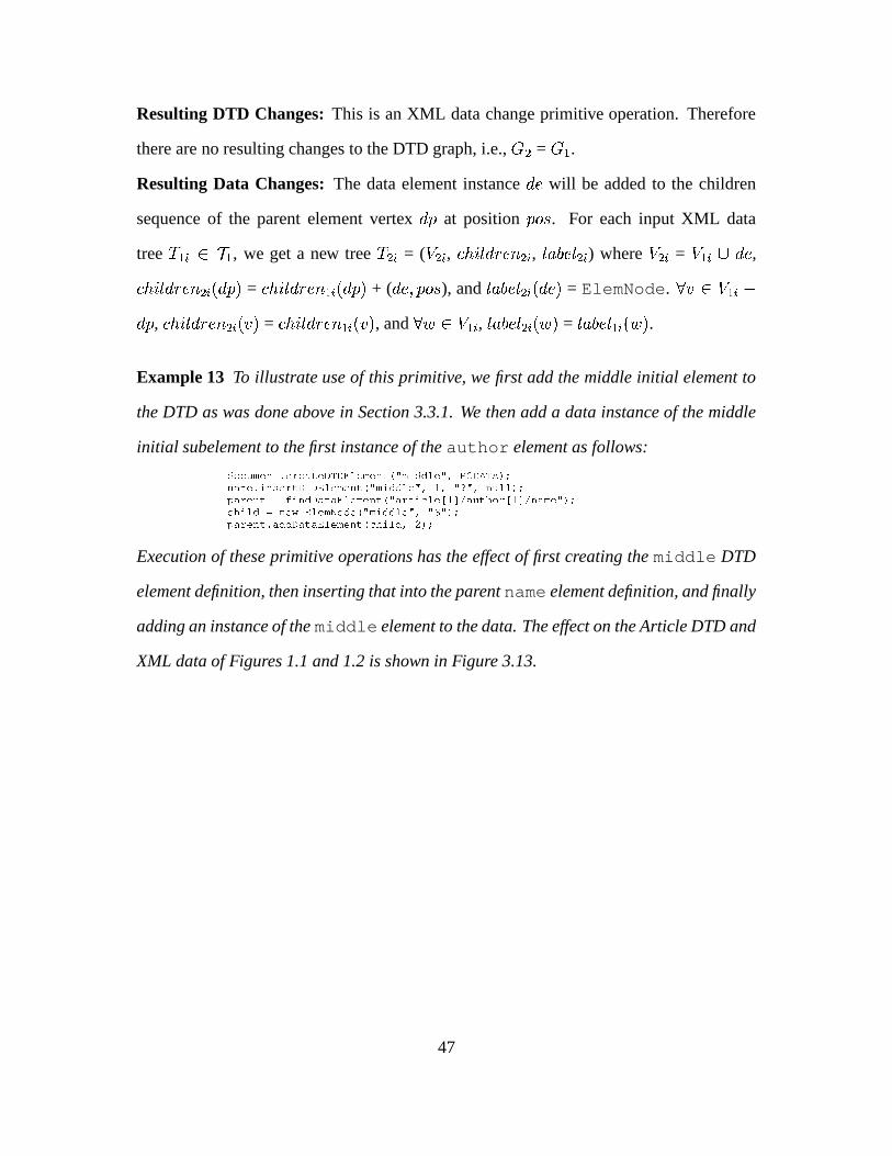
Resulting DTD Changes: This is an XML data change primitive operation. Therefore
there are no resulting changes to the DTD graph, i.e.,�
+ =�
* .
Resulting Data Changes: The data element instance���
will be added to the children
sequence of the parent element vertex� �
at position� ���
. For each input XML data
tree�
* � � � * , we get a new tree�
+ � = (�
+ � , ��� ��� � � / + � , ��� � ��� + � ) where�
+ � =�
* � � ���,
��� ��� � � /+ � � � � � =
��� ��� � � /* � � � � � + (
��� � � ���), and
���������+ � � � � � = ElemNode.
� � � �* � �
� �,��� ��� � � /
+ � � � � =��� ��� � � /
* � � � � , and��� � �
* � , ��������� + � � � �=� ��� ���
* � � � �.
Example 13 To illustrate use of this primitive, we first add the middle initial element to
the DTD as was done above in Section 3.3.1. We then add a data instance of the middle
initial subelement to the first instance of the author element as follows:$!�����4 ��3�� ������������.��.�� ����4 ��3�� � SZ4A��$�$"���AS�� ,�-�.�/��0/ &��3��4"� ��3"@������.��.�������4 ��3�� �ZSZ4���$�$"���AS�� ��9S�%�S�� 3������ &�G�������3���R:?���3�$�.�����������4"��3�� �ZSK����� ��������� � ��Q������� !��� � ��Q�3���4"�AS�&���� ����$�R�3�� � � ����4� !�$�� � S 4���$�$"���5S���S�8 S�&�G�������3�� ��$�$�."�����������4 ��3�� �+�� ����$�� � &��
Execution of these primitive operations has the effect of first creating the middle DTD
element definition, then inserting that into the parent name element definition, and finally
adding an instance of the middle element to the data. The effect on the Article DTD and
XML data of Figures 1.1 and 1.2 is shown in Figure 3.13.
47

����������� �������������������������� �!"��#�$"��%��&�"��"�����'�()+* �,�-����� ��������������� ����������&�!"��#$���%��&����"����"'�()+*����������� ��.���&�����/�10�234�5�� 5,)+* �,�-����� ��.���&�����/�10�2�3"4�5�� 56) *����������� ����!"��#$��7��8��+9���) * �,�-����� ����!"��#$��7��8� 9���) *
�,�:5��"�"��;"<"����!���#$��=�'>;&4>0&?���@A�; ?���4* �,�:5����"��;"<"����!���#$��=�'>; 4B0&?��"@"A�; ?��"4�*L M1NON�P�N�Q�R ��� S�X ��� U���� �� W � � �� \ L�M�NON�P�NQ�R ��� S�X ��� U������ S�U�V�V�W�X� ��+W � � �&\����������� ��GC"���D �H�10�234�5�� 5,)+* �,�-����� ��GC"���D �H�10�2�3"4�5�� 56) *����������� ��=�"�D&�/��0&23"4&5��+5,) * �,�-����� ��=�"�D&�/��0&234�5��+5,)+*����������� ����"��"�����'�� 9�$8$"I�"�&J#F)�K�* L�M�NON�P�NQ�RTS�U�V�VWX ��� Z������R�� �&\����������� ��]9�$�8�$I��� J�#/�������������+��'��&��$"��) * �,�-����� ����"��"�����'�� 9�$8$"I����&J#F)&K*����������� ��Y��'���$��.���2�^* �,�-����� ��]9�$�8�$I��� J�#/������������+��'����$"��)+*
�,�:5��"�"��;"<"�Y�"'����$��.8��+9���3"4&5�� 5_0�;+��2���; ��4�* �,�-����� ��Y��'���$��.��2��^*�,�:5����"��;"<"�Y�"'����$��.8��+9���3"4&5��+5`0�;+�2��; ��4*
���"����"����* �������������*����������*��"���Y���$�&!����$8.����8��I���"�� ���������* �����&�����*�����Y���$���!"���"$�8.���8�"I"���� &���������*����!���#$��=�'����+'���� * �"�!"��#�$"�=�'���� '���� *
�8��+9���* ��8�� 9��*�C"���D&�*4��"�8����"C"���D&�* ��C�"�D&��*�4��"��8�����C�"�D&��*���"�D&��*����"� 9��������"�D&��* <middle>S</middle>��&8� 9��* ����D ��*����� 9���"��"���D ��*
����!��"#�$"��* � &8��+9���*� ��!���#$��"*
����� �:�"��D&�>�DT��#��BD�� 9��E) ����� �1�"��D&�>�DT�"#�>D�+9��E)a ��b�c"?�� 5�b���"?
Figure 3.13: Results of addDataElement Primitive Operation
Primitive 14: destroyDataElement
Syntax: dp.destroyDataElement(ElemNode de, int pos)
Semantics: Remove the data element instance���
from the children sequence of the parent
data element vertex� �
at position� ���
.
Preconditions: An element definition node�
for the vertex���
must exist in the DTD
graph, i.e.,d �
such that � � ��� � � ��� �
=�
. An element definition node�
for the parent
vertex� �
must also exist in the DTD graph, i.e.,d �
such that � � ��� � � � � �
=�
. The
element definition node�
must be an optional child subelement in the parent definition�
,
meaning�
has either quantifier QMARK or quantifier STAR to be allowed to be removed.
Resulting DTD Changes: This is an XML data change primitive operation. Therefore
there are no resulting changes to the DTD graph, i.e.,�
+ =�
* .
Resulting Data Changes: The data element instance� �
will be removed from the chil-
dren sequence of the parent element vertex� �
at position� ���
. For each input XML
data tree�
* � � � * , we get a new tree�
+ � = (�
+ � , ��� ��� � � / + � , ��������� + � ) where�
+ � =�
* �
-���
and��� ��� � � /
+ � � � � � =��� ��� � � /
* � � � � � - (��� � � ���
).� � � �
* � � � �,��� ��� � � /
+ � � � � =��� ��� � � /
* � � � � , and��� � �
* � , ��� � ��� + � � � �=����� ���
* � � � �.
48

Example 14 To illustrate use of this primitive, we remove the middle initial element
which was added in Example 13 above as follows:
G�������3���R:?���3�$�.�����������4"��3�� �ZSK����� ��������� � ��Q������� !��� � ��Q�3���4"�AS�&��G�������3�� $��"@�� ��!�X�."������ ����4 ��3�� � SZ4A��$�$"���AS�� � &�
Execution of these primitive operations causes no changes to the DTD, but has the effect
of restoring the XML data from the previous example to its original form of Figure 1.2:
���"����"����* �������������*����������*��"���Y���$�&!����$8.����8��I���"�� ���������* �����&�����*�����Y���$���!"���"$�8.���8�"I"���� &���������*����!���#$��=�'����+'���� * �"�!"��#�$"�=�'���� '���� *
�8��+9���* ��8�� 9��*�C"���D&�*4��"�8����"C"���D&�* ��C�"�D&��*�4��"��8�����C�"�D&��*<middle>S</middle> ����D ��*����� 9���"��"���D ��*���"�D&��*����"� 9��������"�D&��* � &8��+9���*
��&8� 9��* � ��!���#$��"*����!��"#�$"��*
����� �:�"��D �>�DT��#�>D�� 9���) ����� �:�"��D&�>�DT��#��BD�� 9��E)a ��b�c"?�� 5�b�����?
Figure 3.14: Results of destroyDataElement Primitive Operation
3.4 Completeness of DTD Change Operations
The taxonomy in Section 3.3 intuitively captures all changes needed to manipulate a DTD.
We have taken care to define minimal semantics as well as a minimal set of primitives,
i.e., no primitive defined in the taxonomy subsumes the functionality of another primitive
defined in the taxonomy. In this section we show that this set of changes indeed provides
for every possible type of DTD change (completeness criteria). The proof given here has
its basis on the completeness proof for the evolution taxonomy of Orion [BKKK87].
With the DTD graph we focus primarily on manipulations of nodes and of the directed
edges between parent and children nodes. Towards that end we define seven operations
from those which we have defined for a DTD in Table 3.1 in Section 3.3, mapping our
primitives to ones which correspond to the “essential schema changes” in the Orion tax-
onomy. We prove that every legal DTD graph operation is achievable using this set of
seven operations. The proof is based on the concept of a single-rooted, directed acyclic
49

graph, from hereon referred to as a DAG, to which our DTD graph model conforms. The
set of operations and its basic semantics for the DTD graph are given in Table 3.3. 1
Notation Operation Description TaxonomyEquivalent
op1 add-attribute Adds new attribute to node 3.3.2.9op2 delete-attribute Deletes new attribute from node (element) 3.3.2.10op3 remove-node-edge Removes the edge from parent to node 3.3.2.4op4 add-node-edge Adds an edge between the parent and node 3.3.2.3op5 create-nonattr-node Creates a new node; default is no parent 3.3.1.1op6 delete-nonattr-node Deletes a leaf node 3.3.1.2op7 add-root Adds a given node to the root set R 3.3.1.1
Table 3.3: The DTD Graph Operations.
Lemma 1 For any given DTD graph G, there is a finite sequence of , op6 . that can
reduce the DTD graph G to another DTD graph G�
with only one root node.
Proof: It is apparent that if we repeatedly apply the operation op6 which removes a
non-nested element node n, we can after a finite number of applications reduce any given
DTD graph G to a new DTD graph G�
which only has the root node.
Lemma 2 There is a finite sequence of operations , op1, op4, op5, op7 . that gen-
erates any desired DTD graph G from a DTD graph G�
with only a root node.
Proof: Let G be a DAG with a finite number of nodes, edges and roots and G�
be a
DAG with only a root node, i.e., the document root is a single element. We can observe
the following construction pattern, a finite sequence of operations listed above in Lemma
2, and transform the DAG G�
to become identical to the DAG G.
Traverse DAG G in a breadth-first order and perform the following for each node n
visited:
) For every node n in G, add a corresponding node n�
to DAG G�
using the operation
op5.1We disregard at this point constraints such as #REQUIREDwhich are a semantic extension to the graph
model that could be fairly easily addressed as an extension to the proofs sketched here.
50

) Add all attributes of n to the new node n�
in G�
using the operation op1.
) For each incoming edge into the node n add a corresponding incoming edge to the
node n�
in G�
using the operation op4.
) Let R be the set of nodes directly descended from the root. If the node n exists in
the root set R, add the equivalent node n�
to the root set R�
in G�
using the operation
op7.
The resultant DAG G�
will be equivalent to the initial DAG G as they will have the
same set of nodes N, edges E and roots R.
Theorem 1 Given two arbitrary DTD graphs G and G�
, there is a finite sequence M of
, op1, op4, op5, op7 . , such that M(G)�G
�
.
Proof: We can prove this by first reducing the DTD graph G to an intermediate DTD
graph G1 using Lemma 1. The DTD graph G1 can then be converted to the DAG G�
using
Lemma 2.
Theorem 2 Given two arbitrary DTD graphs G and G�
, there is a finite sequence of
DTD graph operations N of , op1, op2, op3, op4, op5, op6, op7 . , such
that N(G)�G
�
.
Proof: The set of operations , op1, op4, op5, op7 . is a subset of the oper-
ations , op1, op2, op3, op4, op5, op6, op7 . . Hence the completeness of
this set of operations is given from Theorem 1.
3.5 Soundness of Change Primitives
A taxonomy of XML and DTD change primitives is sound if the following properties
hold true:
51

) Every operation on a well-formed input DTD graph produces a well-formed output
DTD graph, and every operation on a well-formed input XML tree produces a well-
formed output XML tree (well-formedness criteria).
) Every operation on a valid set of input XML trees produces a new valid set of output
XML trees (validity criteria).
) Every operation on an input DTD graph which corresponds to a valid set of input
XML trees produces a valid set of output XML trees which are consistent with the
output DTD graph (consistency criteria).
A formal proof of soundness would be rather laborious, requiring proof steps to
demonstrate that each of the above properties holds for each defined primitive. Instead,
we therefore investigate individual primitive operations for each of the above properties
to summarize the soundness proof.
3.5.1 Well-formedness
The soundness criteria under consideration here is to determine whether an operation ap-
plied to the input DTD graph or the input XML trees produces an output DTD graph or
output XML trees respectively which syntactically conform to the XML language speci-
fication as defined in [W3C00]. We choose to look at the changeQuant primitive, an
operation which makes a syntactic change to the DTD.
Prior to executing this primitive, we first ensure that the pre-conditions are satisfied.
Among numerous pre-condition checked at the onset of this primitive operation, the one
which ensures the well-formedness criteria is the one which checks the input QuantType
� . According to the syntax specification in [W3C00], the possible values which are al-
lowed in this context are , STAR - PLUS - QMARK - NONE . . Checking that this pre-
condition is satisfied ensures that we will not introduce any notation into the DTD graph
which is not syntactically permissible.
52
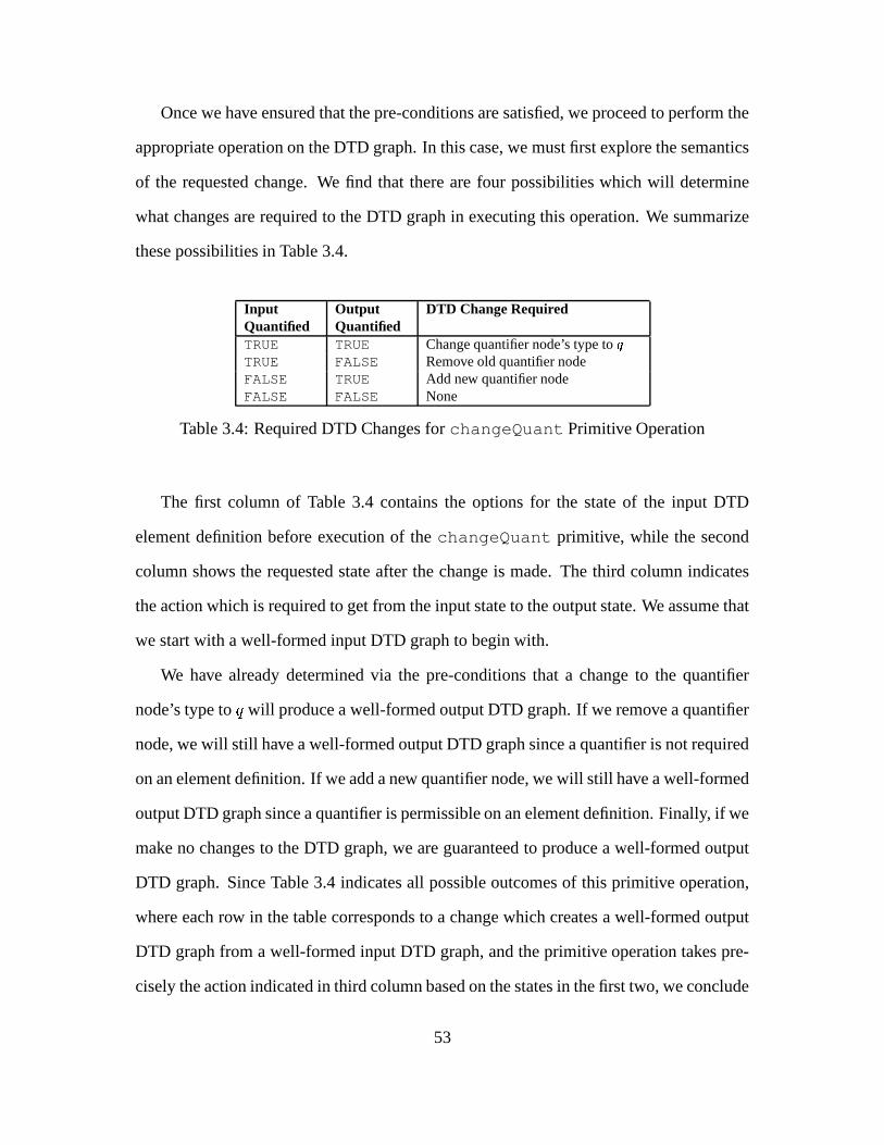
Once we have ensured that the pre-conditions are satisfied, we proceed to perform the
appropriate operation on the DTD graph. In this case, we must first explore the semantics
of the requested change. We find that there are four possibilities which will determine
what changes are required to the DTD graph in executing this operation. We summarize
these possibilities in Table 3.4.
InputQuantified
OutputQuantified
DTD Change Required
TRUE TRUE Change quantifier node’s type to �
TRUE FALSE Remove old quantifier nodeFALSE TRUE Add new quantifier nodeFALSE FALSE None
Table 3.4: Required DTD Changes for changeQuant Primitive Operation
The first column of Table 3.4 contains the options for the state of the input DTD
element definition before execution of the changeQuant primitive, while the second
column shows the requested state after the change is made. The third column indicates
the action which is required to get from the input state to the output state. We assume that
we start with a well-formed input DTD graph to begin with.
We have already determined via the pre-conditions that a change to the quantifier
node’s type to � will produce a well-formed output DTD graph. If we remove a quantifier
node, we will still have a well-formed output DTD graph since a quantifier is not required
on an element definition. If we add a new quantifier node, we will still have a well-formed
output DTD graph since a quantifier is permissible on an element definition. Finally, if we
make no changes to the DTD graph, we are guaranteed to produce a well-formed output
DTD graph. Since Table 3.4 indicates all possible outcomes of this primitive operation,
where each row in the table corresponds to a change which creates a well-formed output
DTD graph from a well-formed input DTD graph, and the primitive operation takes pre-
cisely the action indicated in third column based on the states in the first two, we conclude
53

that the changeQuant operation maintains the well-formedness criteria.
3.5.2 Validity
The soundness criteria under consideration here is to determine whether an operation
applied to the input XML trees produces an output set of XML trees which are still valid
with respect to the associated DTD graph. We assume that the input set of XML trees
is valid to begin with. We choose here to look at the addDataElement primitive, an
operation which makes a change to an XML data tree.
Prior to executing this primitive, we first ensure that the pre-conditions are satisfied.
These include: checking that a DTD element definition exists for the element instance be-
ing added, checking that a DTD element definition exists for the parent element instance
being added to, and checking that the element instance being added is valid at the re-
quested position within the parent element instance. By not allowing an element instance
for which there is no corresponding DTD element definition to be added, we prevent
producing an invalid output XML data tree. By not allowing an element instance to be
added to a parent instance for which there is no corresponding DTD element definition,
we again prevent producing an invalid output XML data tree. Finally, by not allowing a
child instance to be added to a parent instance where such a child is not permissible, we
prevent producing an invalid output XML data tree.
Once we have ensured that the pre-conditions are satisfied, we proceed to perform the
appropriate operation on the XML tree. In this case, we add a data element instance to
the parent element instance in the position indicated by the input parameters. Again, we
have already determined via the pre-conditions that it is valid to insert this new element
instance into the parent at the requested position. We therefore conclude that after the
insertion of the child data element instance into the parent instance, we are left with a
valid output XML tree.
54

3.5.3 Consistency
The soundness criteria under consideration here is to determine whether an operation
applied to the input DTD graph also makes whatever changes are necessary to ensure that
the corresponding XML data trees remain valid and consistent with respect to the output
DTD graph. We choose to look at the removeDTDElement primitive, an operation
which causes changes to both the DTD and the XML data.
Prior to executing this primitive, we first ensure that the pre-conditions are satisfied.
These include: checking that the element definition (�) we are removing actually exists
in the DTD, checking that the parent element definition from which we are removing�
actually contains�
as a subelement, and checking that�
does not contain any children
subelements of its own. We obviously could not remove a DTD element that does not
exist, nor could we remove a child subelement from a parent which does not contain
that child. Finally, removing an element which contains subelements of its own could
potentially violate the consistency criteria.
Once we have ensured that the pre-conditions are satisfied, we proceed to perform the
appropriate operation on the DTD graph. In this case, we remove the subelement�
from
the children sequence of the parent element definition. If we stopped at this point, we
would have a well-formed DTD graph and well-formed XML trees, but the XML trees
would no longer be consistent with the output DTD graph. We therefore continue at this
point to make appropriate changes to the XML trees.
Once we have removed the DTD element definition for the node�
from its parent, we
must now remove all corresponding instances of the node�
from the XML data trees in
order to maintain consistency with the output DTD graph. To do this, we find all instances
of the parent in the XML trees, and remove instances of the child element�
from those
parent instances. Assuming we had a valid and consistent set of input XML trees to
begin with, and by ensuring that the DTD element definition for the node�
did not have
55
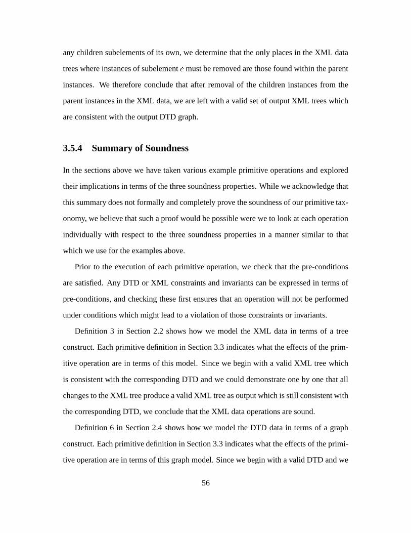
any children subelements of its own, we determine that the only places in the XML data
trees where instances of subelement�
must be removed are those found within the parent
instances. We therefore conclude that after removal of the children instances from the
parent instances in the XML data, we are left with a valid set of output XML trees which
are consistent with the output DTD graph.
3.5.4 Summary of Soundness
In the sections above we have taken various example primitive operations and explored
their implications in terms of the three soundness properties. While we acknowledge that
this summary does not formally and completely prove the soundness of our primitive tax-
onomy, we believe that such a proof would be possible were we to look at each operation
individually with respect to the three soundness properties in a manner similar to that
which we use for the examples above.
Prior to the execution of each primitive operation, we check that the pre-conditions
are satisfied. Any DTD or XML constraints and invariants can be expressed in terms of
pre-conditions, and checking these first ensures that an operation will not be performed
under conditions which might lead to a violation of those constraints or invariants.
Definition 3 in Section 2.2 shows how we model the XML data in terms of a tree
construct. Each primitive definition in Section 3.3 indicates what the effects of the prim-
itive operation are in terms of this model. Since we begin with a valid XML tree which
is consistent with the corresponding DTD and we could demonstrate one by one that all
changes to the XML tree produce a valid XML tree as output which is still consistent with
the corresponding DTD, we conclude that the XML data operations are sound.
Definition 6 in Section 2.4 shows how we model the DTD data in terms of a graph
construct. Each primitive definition in Section 3.3 indicates what the effects of the primi-
tive operation are in terms of this graph model. Since we begin with a valid DTD and we
56

could demonstrate one by one that all changes to the DTD graph produce a valid DTD
graph as output, we conclude that the DTD change operations are sound.
Finally, the primitive definitions in Section 3.3 specify precisely when a change to a
DTD also requires a change to the XML data in order to maintain consistency via post-
conditions. Since any given change will either be rejected due to the pre-conditions not
being satisfied, or will occur in both the DTD and the XML data when required, and since
we could demonstrate one by one that all of our operations fulfill these requirements, we
conclude that our taxonomy of combined DTD and XML change primitives is sound.
57

Chapter 4
XEM Prototype System Design and
Implementation
4.1 Introduction
To verify the feasibility of our approach, we have realized the ideas presented in this thesis
in a functioning prototype system for XML evolution management1, called Exemplar. In
this chapter we first give some general background upon which we base our implementa-
tion. Then we present our system design, including overall architecture, system dictionary
and application classes. Next we discuss our mapping model, and finally provide some
implementation details. In particular, we show how the primitive operations introduced
in Section 3.3 were implemented in Exemplar.
In our background research for this thesis, we found some other projects underway
to map DTDs and XML data to relational database structures [LMZ00, FK99, Koe99].
To distinguish our work, we therefore decided to use an Object Oriented (OO) approach
for Exemplar. In our prototype implementation we use Excelon Inc.’s PSE Pro [Obj93], a1The preliminary prototype system, ReWeb [RCC
�
00] has been demonstrated at ACM SIGMOD 2000.
58
lightweight object database system repository, as the underlying persistent storage system
for DTDs and XML documents. We require that the DTDs with which the incoming XML
documents comply be entered first into the system. PSE Pro’s schema repository has been
enhanced to not only manage traditional OO schemata but also DTDs as meta-data, since
in an XML management system, a DTD serves the purpose of a schema. The DTD-
OO schema mapper generates an OO schema according to the DTD meta-data. Then
we load the XML documents into the just prepared schema. The mapping and loading
details are given below. Comparison of the performance of using our primitives to achieve
incremental change versus reloading from scratch can be found in Chapter 5.
4.2 Exemplar Architecture
Figure 4.1 depicts the architecture of the XML Evolution Management Prototype system
(Exemplar), which provides the facilities to describe desired DTD and XML transforma-
tions via combining the change primitives. Exemplar utilizes functionality provided by
the SERF system [CJR98b], which interacts directly with the database to store and access
the Schema and Object repositories, and also provides the basis for schema evolution.
The main modules of the Exemplar system architecture include the following:
) The DTD-Mapper parses the input DTD and interacts with the System Dictionary
Manager, as described below in Section 4.3.
) The XML-Loader parses the input XML documents and interacts with the Appli-
cation Classes Manager, as described below in Section 4.4.
) The XML-Dumper also interacts with the Application Classes Manager to extract
the XML data stored in the database, and then it writes the results to a new XML
file.
59

) The system management classes which interact with the SERF system include stor-
age, retrieval and maintenance of System Dictionary and Application classes, in
addition to providing the evolution primitive operations.
XML
XML
������������� �
����������������
������������ �
SchemaRepository
ObjectRepository
������� �"!$#�%'&
SERF
DTDSysDictManager
AppClassesManager
Evolution Primitives
Figure 4.1: Architecture of Exemplar System
4.3 System Dictionary and the DTD-Mapper
The DTD-Mapper module is responsible for parsing the DTD, creating system dictionary
objects that model the respective DTD semantics, and populating those objects with the
meta-data found in the DTD. The DTD-mapper then generates appropriate application
classes for each element definition, which are later instantiated by the XML-Loader class.
(See Section 4.4 below.) Figure 4.2 illustrates the system dictionary class hierarchy.
The DTDNode is an abstract base class from which all other DTD classes inherit.
The DocDef is responsible for document-wide concepts such as the unique DTD ID, the
60

DTDNode������� ����� � �� � �������������� ������� � ��� � �������
DocDef� ������� � � ������ � ���������
createDTDElement()destroyDTDElement()renameDTDElement()findElemDef()
GroupDef ���!�"#� � �$�%���
ElemDef����� � �����&� "�� ���!�"#��� �&� ���� $�%���������� � �'��� ��� (�� ���
insertDTDSubElement()removeDTDSubElement()convertToGroup()flattenGroup()changeQuantifier()addDTDAttr()destroyDTDAttr()findAttrDef()changeAttrDefaultType()changeAttrDefaultVal()changeAttrFixedVal()
AttrDef����� � �������"�� ��)!�"#��� �&� $�%��� ��)!�"#����* $�%�������� � ���+����* ��������� � ���+*,� -��������.�
QuantNode ���!�"#/�$�%�0�12���� ��� �+� ��/3!�� � �0�12���� ��� �+� ��4����� ��5 � �
qType:*,+,?,.
����* $�%)��6 �2��/!�� � ���7� "� � � ���7�84� -����
grpType:choice,list
��� �&� $)%��� 6������� � 74� �7� � � ��*97�� � � ��* � 7
enum
��� ��� � �&� $�%���6��������� �7"+� -���� 7'��� "�� ��-7�"��� % 7'� �&%
Figure 4.2: System Dictionary Class Hierarchy
URI for the DTD, and document-level methods that manage top-level element definitions.
A GroupDef object is created for each nested group defined within the DTD element
definitions, and QuantNodes are created whenever an element or group has quantifiers
“*”, “+”, or “?”. An ElemDef object is created for each element definition within the
DTD. Similarly, an AttrDef object is created for each attribute definition. The permissible
values for enumerated types are shown in the small boxes below the class diagrams above.
4.4 Application Classes and the XML-Loader
The XML-Loader module is responsible for parsing the XML document(s) which con-
form to a previously loaded DTD, and instantiating the application classes which were
created by the DTD-Mapper. The XML-Loader then populates the application classes
with data objects according to the XML document file(s). Figure 4.3 illustrates the pre-
61

defined application class hierarchy, and shows some sample application classes.
Figure 4.3: Application Classes Which Represent XML Data
Any is an abstract base class from which all application classes inherit. It contains a
reference to the corresponding DTD element definition found in the system dictionary, a
reference to the parent element, and a vector of children elements. The parent and children
variables are used to keep track of relationships among elements. For example, subele-
ments are stored as children of their parent element. In order to distinguish same-named
elements which come from different DTDs, the application classes are assigned a DTD
ID as part of their name. The element name as it is defined in the DTD is then appended
to this ID. For example, if a “Product” element is defined in two different DTDs, the first
might be named D1 Product, and the second D2 Product. Finally, the predefined
PcData class is used to store the values of XML data elements.
4.5 Mapping Model
Table 4.1 shows how the content types found in the DTD are mapped to corresponding
OO model representations in the system dictionary. Some constructs, such as Document
62

and Element, are represented by the various system dictionary objects described above,
while others, such as constraints, are stored as member variables of those objects.
DTD Content Types OO Model Representation
Document Document Definition objectElement Element Definition objectElement Quantifier Quantifier objectElement Content Constraint contentType member variable in Element objectGroup Group Definition objectGroup Content Constraint grpType member variable in Group objectGroup Quantifier Quantifier objectAttribute Attribute Definition objectAttribute Default Constraint defaultType member variable in Attribute objectAttribute Type Constraint attrType member variable in Attribute object
Table 4.1: Mapping the DTD to System Dictionary Objects
Mapping from DTD and XML files into system dictionary and application classes
proceeds as follows. First, the DTD is parsed by the DTD-Mapper, and instances of the
system dictionary objects are created as indicated for the content types in Table 4.1 above.
Then the DTD-Mapper creates the application classes: one Java source file for each ele-
ment definition found in the DTD. On the application side, DTD attribute definitions are
just mapped to member variables in these Java files. Then subelements are later stored in
the children vector by the XML-Loader which instantiates and populates the application
classes with the XML data.
We illustrate with an example. Below we again show the Article.dtd from Figure 1.1,
along with the DTD graph from Figure 2.2 which models our internal representation of
this DTD once it is processed by the DTD-Mapper. We then describe the system dictio-
nary objects and application classes created by the DTD-Mapper. Finally, we indicate
how the application classes are instantiated and populated by the XML-Loader.
63
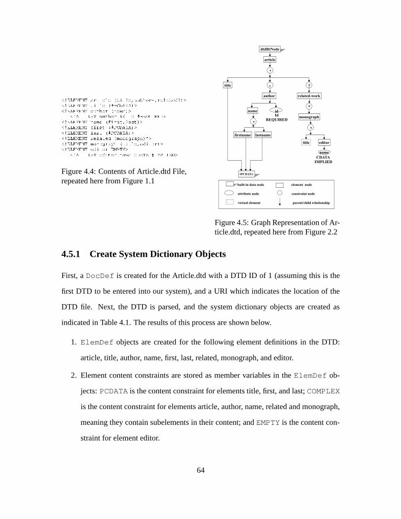
������������� ������� ���������� ���������������� "!���#������"��������$�%�&�'������������� �(� ��� ���)�+*�,-�.�/��0/1&�'������������� �������� !�2��3��4"�5&0'
���6/�������7�8��������� !��9��$:70.:*�;��<�=�7�;���."'������������� �>3���4"�)��?����@��A�����@��5&0'������������� �B?�����@��C�+*�,-�.�/��0/1&�'������������� �D���"@��C�+*�,�-�.�/���/1&0'������������� �9��� �������$��E4 !�3!�F����G 5&�H�'������������� �I4 !�3�!�F"����G C�J����� �����K��$ ���!��&0'������������� �>��$ ���!�I���",��L"'
���6/�������7�8��>��$ ���!��(3���4"��-�.�/���/M*7N�,���70��. '
Figure 4.4: Contents of Article.dtd File,repeated here from Figure 1.1
article
related-work
title
author
firstname
name
lastname
monograph
dtdRtNode
,
+ ?
#PCDATA
editor
*
name
,
title
,
built-in data node element node
virtual element
attribute node
parent/child relationship
constraint node
idId
REQUIRED
CDATA
IMPLIED
Figure 4.5: Graph Representation of Ar-ticle.dtd, repeated here from Figure 2.2
4.5.1 Create System Dictionary Objects
First, a DocDef is created for the Article.dtd with a DTD ID of 1 (assuming this is the
first DTD to be entered into our system), and a URI which indicates the location of the
DTD file. Next, the DTD is parsed, and the system dictionary objects are created as
indicated in Table 4.1. The results of this process are shown below.
1. ElemDef objects are created for the following element definitions in the DTD:
article, title, author, name, first, last, related, monograph, and editor.
2. Element content constraints are stored as member variables in the ElemDef ob-
jects: PCDATA is the content constraint for elements title, first, and last; COMPLEX
is the content constraint for elements article, author, name, related and monograph,
meaning they contain subelements in their content; and EMPTY is the content con-
straint for element editor.
64

3. AttrDef objects are created for the two attribute definitions in the DTD: id (de-
fined in the DTD as an attribute of the author element) and name (defined in the
DTD as an attribute of the editor element).
4. Attribute default constraints are stored as member variables in the AttrDef ob-
jects: REQUIRED is the default constraint for the id attribute, and IMPLIED is the
default constraint for the name attribute.
5. Attribute type constraints are also stored as member variables in the AttrDef ob-
jects: ID is the type constraint for the id attribute, and CDATA is the type constraint
for the name attribute.
6. GroupDef objects are created for groups of more than one child subelement: we
create one GroupDef each for the children of elements article, name, and mono-
graph. There is no need to create GroupDef objects for groups of only one subele-
ment, as would be the case for the children of elements author and related.
7. Group constraints are stored as member variables in the GroupDef objects: LIST
is the constraint for all groups in this example.
8. QuantNode objects are created for each quantifier, in this case one for the “+” in
author+, one for the “?” in related?, and one for the “*” in (monograph)*.
4.5.2 Create Application Classes
The next task accomplished by the DTD-Mapper is to create application class definitions
for each element in the DTD. This is done by creating Java source files, named according
to the element name in the DTD, prepended by the DTD ID, adding member variables
for attributes where required, and then compiling the Java files to create the byte-codes.
Each of these Java classes inherits from the pre-defined application class “Any”. Table
4.2 shows the Java source files which get created by the DTD-Mapper when processing
65

the Article.dtd in our example, and the member variables (if any) associated with those
Java files.
Java Source File Name Member VariablesD1 article.java noneD1 title.java noneD1 author.java name=“id”, type=StringD1 name.java noneD1 first.java noneD1 last.java noneD1 related.java noneD1 monograph.java noneD1 editor.java name=“name”, type=String
Table 4.2: Application Classes Created by DTD-Mapper
4.5.3 Instantiate and Populate Application Classes
At this point the DTD-Mapper has finished its job, and the XML-Loader takes over. It
is the XML-Loader’s responsibility to instantiate the application classes just created by
the DTD-Mapper, and to populate them with the XML data. For our example, we again
present the XML file from Figure 1.2 which corresponds to the Article.dtd in Figure 1.1,
along with the XML tree from Figure 2.1 which models our internal representation of this
XML data once it is processed by the XML-Loader.
66

<article>��� ��� ���'�O��"�>��P !��������!�3 � ��3���F��"���"Q�� ��� ���'�������� !��9��$�RTSN$�UAS�'��3���4"�"'�"?�����@�� '�. ����3���� Q�?�����@�� '����"@��"'�V"����4"���� Q����"@��"'
� Q�3���4 �'�"Q������� !��'�������� !��9��$�RTSN���S�'��3���4"�"'�"?�����@�� '�� ��U����"Q�?����@��"'����"@��"'�;���3�$���3"@����"��3�����"Q����"@��"'
� Q�3���4 �'�"Q������� !��'����� ��������$'��4 !�3�!�F����G "'��� ��� ���"'0� !�$����3>.�����W��@��B8�X"@�����4�@��"Q0����� ���'����$ ���!� 3��4"��RMS Y !�3>V �K41S0'�� Q���$"���!���'
� QN4 !�3!�F����G '�"Q����"�������$'
</article>
Figure 4.6: Contents of Sample.xmlFile, repeated here from Figure 1.2
article
title author author
�����EvolutionManager
id idname name
dk er
first last first last
related
monograph
title editor
name���������
DatabaseSystems
Won Kim
Diane Kramer Elke Rundensteiner
ElemNode
AttrNode
ValueNode
�� �� ����� � ����� � ��� ��� �� � ���� ��� !
Document
DocNode
Figure 4.7: Tree Representation of Sam-ple.xml, repeated here from Figure 2.1
To describe the objects created by the XML-Loader, we start with the leaf nodes at
the bottom of the tree, and work our way up. First, six instances of the pre-defined
application class “PcData” are created for the following text values, and the text is stored
in the “value” member variables, one per instance:
"$#&%('*),+(-*.(/10(2*3(.546'*754*7(8(9(:; #&<*3(754*9= #&>*:(75?*9(:@$#&+*/(A(9B$#&C(0(4*D(954*E52F9(354*9(:G #&'*.(D(9(:546<F752*75H*7(E(96I5J*E52*95?*E
Next, two instances of D1 first are created, and each is assigned a single child in its
children vector: One for Diane, which gets assigned PcData instance number 2 above,
and one for Elke, which gets assigned PcData instance number 4 above. Similarly, two
instances of D1 last are created, and assigned instance numbers 3 and 5 above in their
respective children vectors. Two instances of D1 title are created next, and assigned in-
stance numbers 1 and 6 above in their respective children vectors. Then one instance of
D1 editor is created, and the “name” member variable is assigned the String value “Won
Kim”. Next, two instances of D1 name are created. The first of these is assigned the
67

two children, D1 first and D1 last, for Diane and Kramer. The second is assigned the
two children, D1 first and D1 last, for Elke and Rundensteiner. Next, one instance of
D1 monograph is created, and the instance of D1 title for number 6 above, plus the in-
stance of D1 editor are assigned to its children vector. Then two instances of D1 author
are created. The first of these is assigned the String value “dk” to its “id” member vari-
able, and the first instance of D1 name to its children vector. The second instance of
D1 author gets the String value “er” assigned to its “id” member variable, and the second
instance of D1 name to its children vector. Next, an instance of D1 related is created,
and the D1 monograph instance is assigned to its children vector. Finally, one instance of
D1 article is created, and assigned to its children vector are the instance of D1 title, the
two instances of D1 author, and the instance of D1 related.
4.6 Implementation Details
4.6.1 Development Environment
Goals for the Exemplar system include to provide Object-Oriented storage, manipulation
and retrieval of DTD and XML data, and to provide a platform-independent execution
environment. We therefore chose Excelon Inc’s PSE Pro [Obj93] for our database reposi-
tory, and the Java 2 programming language (JDK 1.3 from Sun Microsystems [Sun00]) for
our implementation. For the XML parser, we used XML4J/Xerces, version 3.0.1 (IBM’s
XML parser for Java [IBM00b]). Development was done on the Microsoft Windows NT
platform. In total, the implementation contains 54 Java class files, and over 10,000 lines
of code.
68

4.6.2 SERF System
Excelon’s PSE Pro is a rudimentary Java object store, which does not contain many of
the evolution facilities provided by traditional database management systems. On top of
PSE we have a base evolution support layer called SERF [CJR98b], which provides more
powerful mechanisms for Object-Oriented storage, maintenance and retrieval, including
schema evolution. SERF models OO classes by means of an object called MetaClass,
which we utilize in Exemplar to represent an XML element definition. An Attribute
is also represented in SERF, originally designed to model member variables in OO, and
used in Exemplar to represent an XML attribute definition. Each instance of MetaClass
contains a Java vector of attributes.
When an instance of an application class object is created in SERF (for example,
when we create an instance of D1 author, D1 title, etc.), that instance is added to the
extent of the corresponding MetaClass. This mechanism is used during schema evolution
to determine the set of objects which are affected by a change to an OO class (or in our
case, a change to an XML element definition). The schema evolution functions provided
by SERF include methods such as add attribute and delete attribute, which perform a
complicated set of activities in order to maintain consistency between the application
class objects and the schema repository. For example, the following steps are required in
order to execute an add attribute transaction on a Java class “A”:
1. Create a new Attribute object.
2. Update the MetaClass object for A to reflect the newly added attribute. This
entails the simple addition of a new object (attribute) to a collection (vector) in
Java.
3. Create a new temporary Java source file, A�
, containing all of the code from the
original class file A, plus the additional new attribute.
69

4. Compile and post-process the temporary Java file, A�
. Post-processing is a step
required by PSE, which annotates the compiled class file with mechanisms used
internally by the ObjectStore database.
5. For each instance of class A, create a new instance of class A�
, copying the data
from the object of type A into the new object of type A�
. During this step the newly
created objects are added to the extent of A�
.
6. Swap the object identifiers (OID’s) for each pair of objects: original instance of A
and corresponding newly created instance of A�
. This allows references, which used
to point to type A objects, to now refer to the new type A�
objects.
7. Delete the old objects of type A, removing them from the extent of A, and delete the
old class file A. After completion of this step, the database is in a consistent state
with the newly added attribute, but the class file has the temporary name A�
, and the
objects are of type A�
.
8. Create a new Java file called A, containing all of the code from class file A�
.
9. Compile and post-process the newly defined Java file A.
10. For each object in the extent of class A�
, create an instance of the new class A,
copying the data from the object of type A�
into the new object of type A. During
this step the newly created objects are added to the extent of A.
11. Swap the OID’s for each pair of objects: temporary instance of A�
and newly created
instance of A.
12. Delete the temporary objects of type A�
, removing them from the extent of A�
, and
delete the temporary class file A�
. After completion of this step, the database is in a
consistent state with the newly added attribute: the class file has the correct name
A, and the objects are of the correct type.
70

4.6.3 Missing Functionality
Although Exemplar requires all of the above functionality to be in place in order to prop-
erly perform the desired transformations on DTD and XML data, some of the steps above
were not implemented in SERF due to a complication in the Java Virtual Machine (JVM),
and had to be filled in by the developers of Exemplar. To be precise, steps 1 through 5
were implemented in SERF, providing the functionality for in-memory transformations
only, leaving the name of the class file and the object types in an inconsistent state. The
complication arose at the completion of step 9, because at this point there are two distinct
class files defined with the same name: the original class file called A, and the newly
defined class file with the additional attribute, also called A. Help was elicited from the
producers of PSE [Obj99] to implement the underlying functionality required to swap
OID’s in the database. But this functionality was not fully integrated into the SERF sys-
tem, nor tested, because of the above mentioned difficulty in the JVM.
A theoretical solution to the JVM problem was proposed in [LB98], work which de-
scribes dynamic class loading in Java. The paper provides a solution via a custom class
loader, which can load in a newly defined class with a pre-existing name. Using this
method, a Java class can no longer simply be referred to by its name, but must also be
qualified by its class loader. This solution was implemented in Exemplar [KSC�
01]. Hav-
ing this functionality in place, the SERF system could then be augmented to include the
swapping of OID’s, completing the required functionality for schema evolution.
4.6.4 Primitive Operations
The following list of primitives were implemented in Exemplar:
1. Changes to the Document:) createDTDElement) destroyDTDElement
71
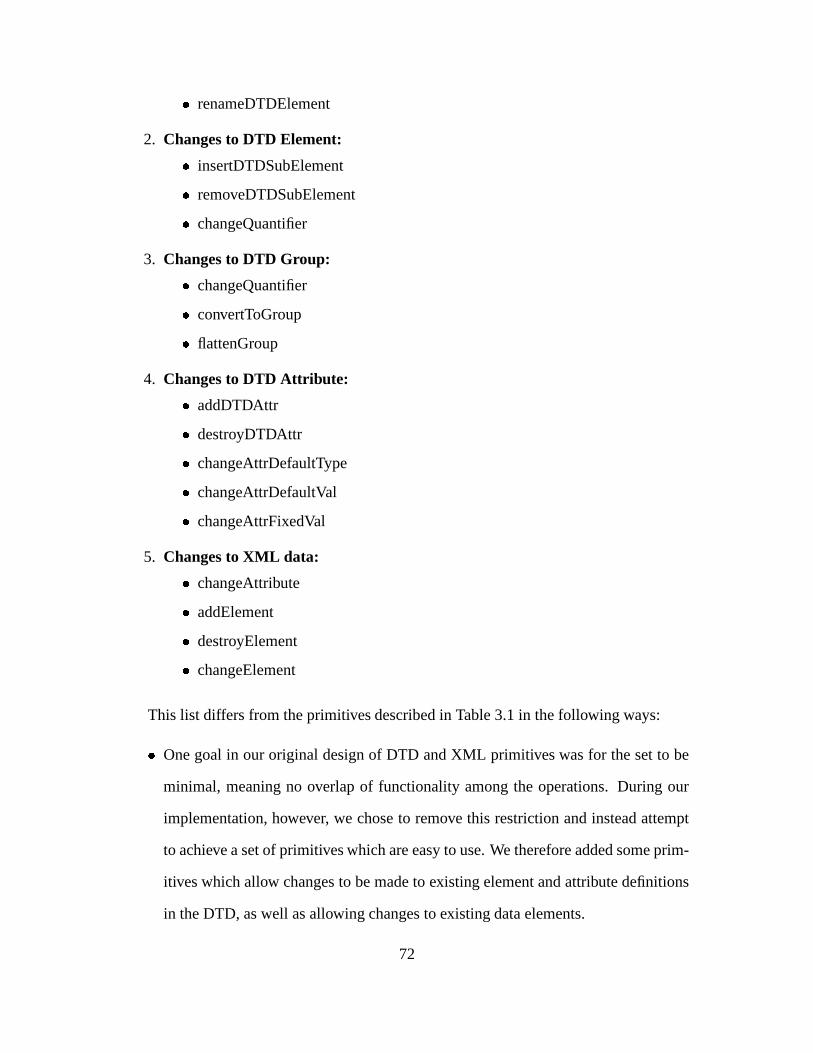
) renameDTDElement
2. Changes to DTD Element:) insertDTDSubElement) removeDTDSubElement) changeQuantifier
3. Changes to DTD Group:) changeQuantifier) convertToGroup) flattenGroup
4. Changes to DTD Attribute:) addDTDAttr) destroyDTDAttr) changeAttrDefaultType) changeAttrDefaultVal) changeAttrFixedVal
5. Changes to XML data:) changeAttribute) addElement) destroyElement) changeElement
This list differs from the primitives described in Table 3.1 in the following ways:
) One goal in our original design of DTD and XML primitives was for the set to be
minimal, meaning no overlap of functionality among the operations. During our
implementation, however, we chose to remove this restriction and instead attempt
to achieve a set of primitives which are easy to use. We therefore added some prim-
itives which allow changes to be made to existing element and attribute definitions
in the DTD, as well as allowing changes to existing data elements.
72

For example, in the original set of primitives, we provide createDTDElement and
destroyDTDElement. These two primitives combined allow for any desired changes
to element definitions in the DTD. In our implementation, however, we additionally
supply a renameDTDElement primitive, which provides the combined functionality
of removing an element using destroyDTDElement and adding the same element
with a different name using createDTDElement. The renameDTDElement primi-
tive therefore allows for more ease of use by combining the two operations into one
method call.
) The original list of primitives in Table 3.1 includes one method called change-
Quant for changing the quantifier of an element, and another method called change-
GroupQuant for changing the quantifier of a group. Both of these two primitives
were implemented using a single method called changeQuantifier for two reasons.
One, it was determined that much of the functionality is the same, and two, it is not
difficult to determine inside the method which of the two types (element or group)
we are dealing with.
) The original list of primitives includes two data change methods called addDataAttr
and destroyDataAttr. Since an attribute is modeled by a member variable of a Java
class in our Exemplar system, it is not possible to add or remove a data instance
of an attribute. Adding or removing an attribute is effectively a schema evolution
operation, as described in Section 4.6.2. Therefore we have only implemented the
changeAttribute primitive, which changes the value of a data instance of an at-
tribute. This way it can be used to simulate the removal an instance of an attribute
which is not required by simply setting its value to null.
73

4.6.5 Indexing Algorithm
Of the many different algorithms used to implement Exemplar, one in particular deserves
mention. During the design phase of the evolution primitives, we knew that we would
need to refer to the subelements contained in a DTD element definition by position. This
can be seen in Table 3.1, where we refer to various subelements by position, for example,
in the insertDTDSubElement primitive. When it came to implementing these primitives,
we found that a simple integer index would be insufficient, since element definitions can
be nested within groups, and subelements can be repeated within a single definition. Ad-
ditionally, when it comes to an insert operation, we need a way to distinguish between
“insert before” and “insert after”. Plus, we need to refer to a nested group by position, in
addition to referring to a single element, in order to accomplish the flattenGroup primi-
tive, for example. We therefore devised the following mechanism for referring to “content
particles” (either an element or a group) which may appear in an element definition.
An index is represented as a linked list of integers, where the length of the list specifies
the depth of the index in the DTD graph (the number of nested groups). The number at
each level in the linked list specifies the ith child at the corresponding level in the DTD
graph. An index of 0 at the last level means “insert before”; any other number means
“insert after”. To illustrate, we use the following original DTD element definition: (a,
(b, c, (d, e))), and the insertDTDSubelement primitive. Table 4.3 shows the
format of our indexing notation in the first column, and the result of inserting a DTD
subelement into the above element definition using that index in the second column. The
dashes (-) in the index notation indicate the links in the linked list. In other words, an
index with notation 2-3-1 represents three integers in a linked list, where the first integer
is 2, linked to the second integer, 3, followed by a link to the final integer, 1.
74

Index DTD definition after in-serting element “x”
0 (x, a, (b, c, (d, e)))1 (a, x, (b, c, (d, e)))2-0 (a, (x, b, c, (d, e)))2-1 (a, (b, x, c, (d, e)))2-2 (a, (b, c, x, (d, e)))2-3-0 (a, (b, c, (x, d, e)))2-3-1 (a, (b, c, (d, x, e)))2-3-2 (a, (b, c, (d, e, x)))2-4 (a, (b, c, (d, e), x))2 (a, (b, c, (d, e)), x)
Table 4.3: Indexing a Content Particle in a DTD Element Definition
It is important to note that the indices discussed above are only used as parameters to
the method calls of the evolution primitives, and we do not store indices in the element
definitions themselves. If we did, this would introduce the complication of having to re-
index subelements when one is added or removed. Rather, we store subelements in the
children vector of the parent element definition. Therefore, when we add or remove a
subelement, the indices are automatically maintained internally by the Java vector class.
75
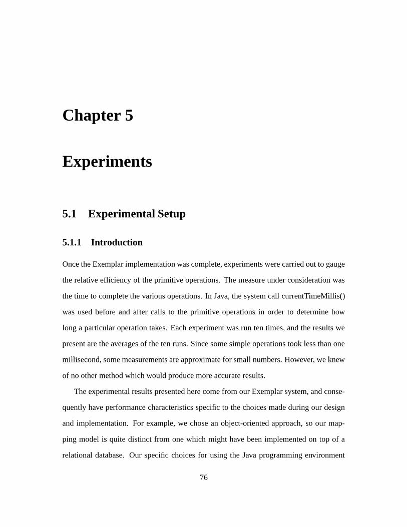
Chapter 5
Experiments
5.1 Experimental Setup
5.1.1 Introduction
Once the Exemplar implementation was complete, experiments were carried out to gauge
the relative efficiency of the primitive operations. The measure under consideration was
the time to complete the various operations. In Java, the system call currentTimeMillis()
was used before and after calls to the primitive operations in order to determine how
long a particular operation takes. Each experiment was run ten times, and the results we
present are the averages of the ten runs. Since some simple operations took less than one
millisecond, some measurements are approximate for small numbers. However, we knew
of no other method which would produce more accurate results.
The experimental results presented here come from our Exemplar system, and conse-
quently have performance characteristics specific to the choices made during our design
and implementation. For example, we chose an object-oriented approach, so our map-
ping model is quite distinct from one which might have been implemented on top of a
relational database. Our specific choices for using the Java programming environment
76

and other third-party tools also play a significant role in the results we achieved when
experimenting with Exemplar.
Due to the nature of PSE, the underlying database system, once a change has been
made to data in memory, it is necessary to “commit” the transaction. This has the effect of
writing the changes to disk, saving them in more permanent storage. While implementing
the XEM primitives, a decision was made not to include the commit operation within the
primitive itself in order to make the primitives more database-independent. This means
that the caller is responsible for starting a transaction before invoking a primitive, and
committing the transaction afterwards.
All primitive operations return a boolean result, allowing the caller to determine
whether the operation was successful. If any error occurs during the primitive execu-
tion, in addition to returning a boolean value of false, an exception is raised, indicating
precisely what went wrong. The decision not to include the commit inside a primitive op-
eration also provides more flexibility to the caller, since it allows one to “bundle” multiple
primitive operations into a single transaction. Since the time to commit a transaction is
dependent on the underlying database system, and not under the control of the Exemplar
developers, the experimental results do not include the time to commit a transaction. In
this way it was possible to examine purely the time to execute an evolution operation.
5.1.2 Execution Platform
All experiments were performed on the same machine in order to make proper com-
parisons. The execution platform is Microsoft Windows NT Enterprise Server Edition,
version 4.0, with service pack 6. The processor in the machine is an Intel Pentium II,
with an operating speed of 433 MHz. The amount of memory in the machine is 128
Megabytes. Although it is not possible to determine at all times all of the processes run-
ning on the machine due to system services and operating system activities that run in the
77

background, an attempt was made to minimize other processes running on the machine
while the experiments were executing. One step that was taken to ensure this was to close
all applications during the execution of the experiments, with the exception of the DOS
command window used to run the experiments.
5.1.3 Data Set Statistics
While testing the time that various primitive operations take, the primary variables which
can be altered for experimental purposes include the following:
) The number of element and/or attribute definitions in a DTD
) The level of nesting of subelements in the element definitions
) Which element or attribute to perform an operation on
) Which primitive operation to perform (schema or data changes, for example)
) The number of data elements in an XML file
) The number of XML files processed
In order to run the experiments it was necessary to have at least one DTD and prefer-
ably many XML files conforming to that DTD to work with. In preparing for the exper-
iments, one option considered was to manually create a synthetic DTD and some XML
files from scratch. But it was determined that a better option would be to find some “real
life” data files to work with. We thus selected the set of Shakespeare’s plays [Bos] for our
experiments. Some statistics about the Shakespeare files are as follows:
) 1 DTD with 21 element definitions
) 37 XML data files, one play per file
) Smallest data file is 141,345 bytes long, and contains 3133 Elements
78

) Largest data file is 288,735 bytes long, and contains 6600 Elements
) Average data file is 213,449 bytes long, and contains 4840 Elements.
Since the original Shakespeare DTD did not contain any attribute definitions, in or-
der to test our primitives that deal with attributes, we simply had to add some attributes
first. Once added, other manipulation operations became possible. All of the experi-
ments described below were executed on this set of Shakespeare XML data files and their
corresponding DTD.
5.2 Experimental Results
Below we show the results obtained from our experiments run on the Exemplar system.
For each experiment we plot the total execution times of various operations under con-
sideration. We also analyze the results in terms of the number of objects in the system
which are affected by an operation. In order to show the execution times in detail, some
of the results are broken out into separate charts with different time scales (seconds vs.
milliseconds).
5.2.1 Exemplar System Initialization
The purpose of the first experiment was to examine the Exemplar system initialization.
We used a fixed DTD and varied the amount of XML data to load. Eight different tests
were run, each time increasing the number of XML data files processed, and each test was
run ten times to get an accurate measure. The results presented are the averages of the ten
runs. We measured the time to map the DTD elements to system dictionary classes, plus
the time to load the XML data, plus the time to dump out the XML data. Also included in
the measurements is the time to initialize and shut down the database. The first two charts
79

below show the varying amounts of time to accomplish these tasks, separated into two
different charts because they are in different time scales. The third chart shows the total
execution time for all of the tasks combined, while the fourth chart compares the amount
of time to load versus the time to dump on a per-element basis.
�������������� �� ������������������������ � ��!
0.0
0.5
1.0
1.5
2.0
1 5 10 15 20 25 30 35"$#�%�& ')()*,+ - .0/1(2#,3045.0467 89 :;9<=>? @ A B A CEDGF
create sys dictH5IEJ CED K0L B DGF
Figure 5.1: Low End Times for System Initialization
Figure 5.1 shows the fixed costs associated with initializing the database, creating the
system dictionary classes, and then shutting down the database. Although they are not
strictly straight lines, we consider these to be fixed costs because they do not vary by
much. If we had included these times in Figure 5.2, the next chart below, they would
indeed appear as straight lines relative to other higher costs, and they would all overlap
each other at the bottom of the chart. We separate them out here in order to “zoom in” and
see the detail of the results. Initializing and shutting down the database are understandably
fixed costs. In this experiment, creating the system dictionary classes is also a fixed cost
because we use the same single DTD for each test. Since all of the XML files conform to
this DTD, each test takes roughly the same amount of time to create the system dictionary
classes.
80

����������� ���������������������� ������� �����
050
100150200250300350
1 5 10 15 20 25 30 35 "!$#%'&)(+*�, - .0/1(2!43652.65
78 9: ;< :=>?@ A
gen app classesB C6DFEHG'I)J�K�L B MFNEPO4Q�RSG�IHJSK�L B MFN
Figure 5.2: High End Times for System Initialization
Figure 5.2 shows the fixed time it takes to generate the application classes, and the
increasing times to load and dump out the XML files. Generation of application classes is
a fixed cost in this experiment, again because we use the same single DTD for each test.
This fixed cost is included in this chart rather than the previous chart because the time
scale is considerably different: close to 50 seconds, as opposed to one or two seconds. As
expected, the time to load and dump out the XML data increases as the amount of XML
data increases.
TVUHWYXHZ�[]\�^`_Ya�b�c�\�c�d]e�c�f�d]\�c�g�bih�j]k`l
0100200300400500600700
1 5 10 15 20 25 30 35mon6p'q`rVs1t�u v w2x+s�n�y{z�w2z
|} ~� �� ����� � Total
ProcessingTime
��� ��� ���������� � ��� �{�����2��� ���- gen app classes��� �����2��� ��� � � ������������2��� ��� � � ���������������� �0�{���
Figure 5.3: Total Times for System Initialization
Figure 5.3 shows the combined times to initialize the Exemplar system, over vary-
ing amounts of XML data. The chart includes the time to initialize and shut down the
database, the time to create system dictionary classes and generate application classes,
plus the time to load and dump the XML data. This chart provides an overall picture of
the costs associated with Exemplar system initialization.
81
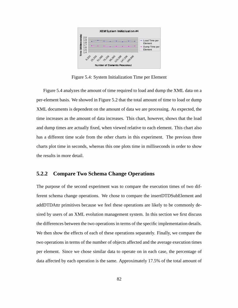
���������� ����� ��� ��� ��� � ������� ������
1.41.51.61.71.81.92.0
6,32
0
25,2
55
51,0
85
75,1
56
99,3
65
123,
288
147,
206
169,
908
�! �"$#&%('�)�*�+�, %-".%-/0 132�' )�4-%-1-1-%(5
67 89:;7<<7 =9>?@A =B
Load Time perElementDump Time perElement
Figure 5.4: System Initialization Time per Element
Figure 5.4 analyzes the amount of time required to load and dump the XML data on a
per-element basis. We showed in Figure 5.2 that the total amount of time to load or dump
XML documents is dependent on the amount of data we are processing. As expected, the
time increases as the amount of data increases. This chart, however, shows that the load
and dump times are actually fixed, when viewed relative to each element. This chart also
has a different time scale from the other charts in this experiment. The previous three
charts plot time in seconds, whereas this one plots time in milliseconds in order to show
the results in more detail.
5.2.2 Compare Two Schema Change Operations
The purpose of the second experiment was to compare the execution times of two dif-
ferent schema change operations. We chose to compare the insertDTDSubElement and
addDTDAttr primitives because we feel these operations are likely to be commonly de-
sired by users of an XML evolution management system. In this section we first discuss
the differences between the two operations in terms of the specific implementation details.
We then show the effects of each of these operations separately. Finally, we compare the
two operations in terms of the number of objects affected and the average execution times
per element. Since we chose similar data to operate on in each case, the percentage of
data affected by each operation is the same. Approximately 17.5% of the total amount of
82

data loaded is affected on average by the execution of each primitive operation.
Both the insertDTDSubElement and addDTDAttr primitives operate on the DTD.
Thus in XML context, they are both schema changes. As is often the case with a schema
change, both operations require an “implied” data change, described in more detail below.
On the surface, the operations appear to be similar. However, due to our implementation,
what happens in each case is quite distinct.
The first operation, insertDTDSubElement, requires a simple change to the structure
of the DTD: an existing element is added to the children of some parent element definition.
The children vector itself does not change, only the contents change. This operation also
implies a data change: for any instance of that parent element in the data, an instance of
the child must also be created and inserted.
The second operation, addDTDAttr, also requires a change to the structure of the
DTD, but this one is not so simple. As described in Section 4.6.2, when a new attribute
definition is created and added to some element definition, this requires making a change
to the Java file which represents that element. Once a change to a Java file is introduced,
the process becomes complicated by the need to create temporary files, copy objects, swap
OID’s, etc. Hence this second primitive operation is expected to take more time than the
first. This expectation is indeed verified by the experiments, as shown in the charts below.
Figure 5.5 shows the initial results of testing the insertDTDSubElement primitive,
while Figure 5.6 shows those of the addDTDAttr primitive. As was done in the first ex-
periment involving system initialization, eight different tests were run for each primitive,
increasing the number of XML data files processed, and again, each test was run ten times
for accuracy. Both charts in Figures 5.5 and 5.6 compare the total time to load all of the
XML data from scratch against the time to execute one of the two primitives. It is clear
from these two that the addDTDAttr operation takes longer than the insertDTDSubele-
ment operation.
83
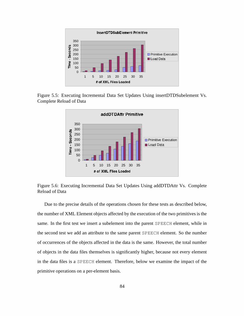
������������ ��������������������������������������
050
100150200250300350
1 5 10 15 20 25 30 35�! #"�$�%'&)(+*�,�-�./&+ +0�1+-�1
23 4567 589:; <
Primitive Execution=�>�?�@BA�?�C ?
Figure 5.5: Executing Incremental Data Set Updates Using insertDTDSubelement Vs.Complete Reload of Data
D�E'E�F/G�F'H�IJILKNMNKPO�QRO ILO S�T
0
50
100
150
200
250
300
350
1 5 10 15 20 25 30 35U�V�W�X�Y�Z\[�] ^ _+`�Z�V�acb�_cb
de fg hi gjklm n
Primitive Executionocpcqcrtsuqcvwq
Figure 5.6: Executing Incremental Data Set Updates Using addDTDAttr Vs. CompleteReload of Data
Due to the precise details of the operations chosen for these tests as described below,
the number of XML Element objects affected by the execution of the two primitives is the
same. In the first test we insert a subelement into the parent SPEECH element, while in
the second test we add an attribute to the same parent SPEECH element. So the number
of occurrences of the objects affected in the data is the same. However, the total number
of objects in the data files themselves is significantly higher, because not every element
in the data files is a SPEECH element. Therefore, below we examine the impact of the
primitive operations on a per-element basis.
84
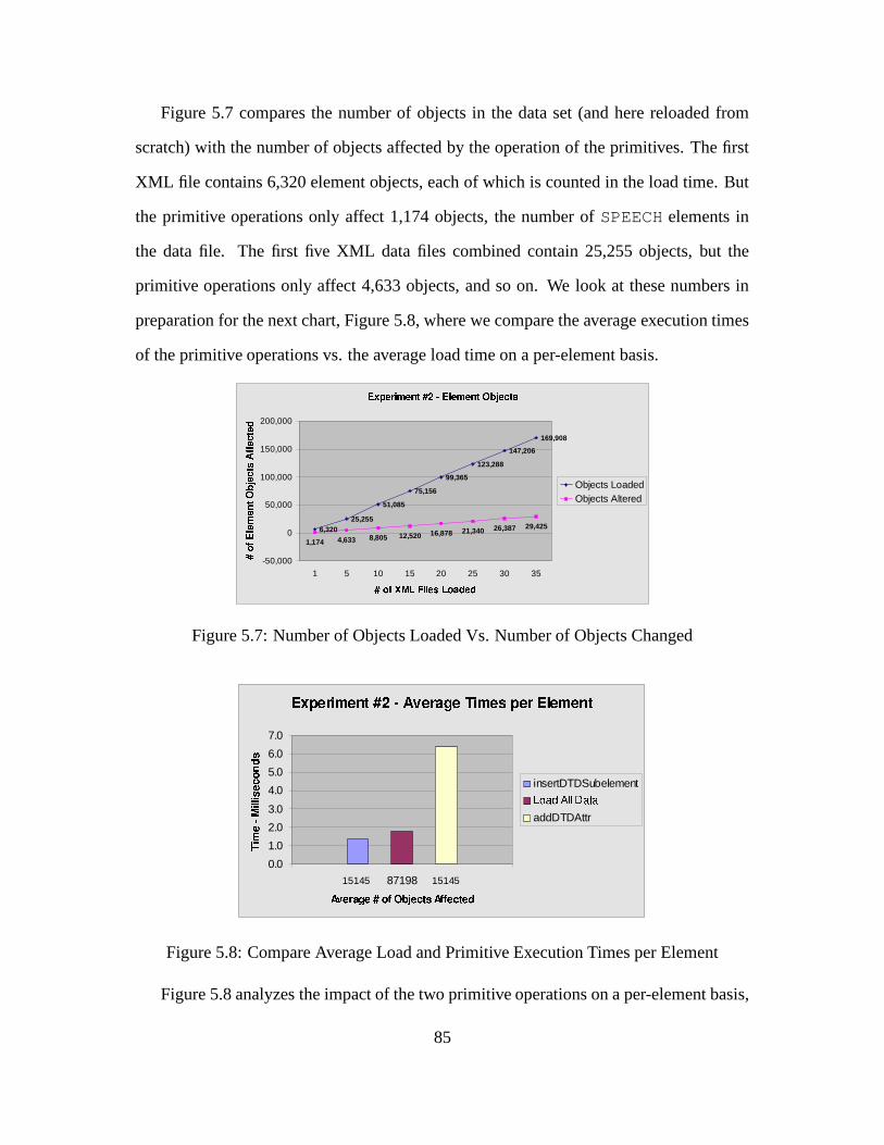
Figure 5.7 compares the number of objects in the data set (and here reloaded from
scratch) with the number of objects affected by the operation of the primitives. The first
XML file contains 6,320 element objects, each of which is counted in the load time. But
the primitive operations only affect 1,174 objects, the number of SPEECH elements in
the data file. The first five XML data files combined contain 25,255 objects, but the
primitive operations only affect 4,633 objects, and so on. We look at these numbers in
preparation for the next chart, Figure 5.8, where we compare the average execution times
of the primitive operations vs. the average load time on a per-element basis.
���������� ����� ���������� ������� ������ ����
6,32025,255
51,085
75,156
99,365
123,288
147,206
169,908
4,6331,1748,805 12,520 16,878 21,340 26,387 29,425
-50,000
0
50,000
100,000
150,000
200,000
1 5 10 15 20 25 30 35�"!$#�%'&)(+*�� � �� ,(�!�-�.���./ 0123454678 9:4;7 <=11 4;7 4>
Objects LoadedObjects Altered
Figure 5.7: Number of Objects Loaded Vs. Number of Objects Changed
?"@BADCBEGFIHJCLK�MONQPSR�TVU�CLEXWZYQC\[LFIHJCZ]^A_C`E,?Va C`HbCcK)M
0.0
1.0
2.0
3.0
4.0
5.0
6.0
7.0
87198dfefgDh ikjfgOlQmfnDo'prq gfs�t u'dfnvn gfs�t gfw
xy z{ |}y~~y �{���� �
insertDTDSubelement�f���f����� ���Q�r�v�addDTDAttr
15145 15145
Figure 5.8: Compare Average Load and Primitive Execution Times per Element
Figure 5.8 analyzes the impact of the two primitive operations on a per-element basis,
85

and compares this result with the average time to load all of the elements from the data set.
The numbers across the bottom of the chart along the X axis show the average number of
objects affected in each case. Here we sum the numbers from the lines plotted in the chart
of Figure 5.7, and divide the sums by 8 to come up with 15,145 and 87,198, the average
number of objects affected by the primitives vs. the average number of objects loaded
respectively. The numbers along the Y axis indicate the execution times in milliseconds,
and we determine the height of each bar by similarly averaging the load and primitive
execution times per element. We show averages in this chart rather than individual times
for each test because we determined that the cost in terms of execution time per object
is independent from the number of objects in the data set. From these numbers we also
calculate the percentage of objects affected by the primitive operations out of the total
number of data elements, which is approximately 17.5%.
From the chart in Figure 5.8 it can be seen that the first primitive, insertDTDSubele-
ment, is more efficient than reloading the data from scratch, as it takes less time per ele-
ment than loading does. But the addDTDAttr primitive takes too much time per element
to be efficient when compared to how long it takes to reload the same data. Therefore it
is possible to conclude that if the user chooses to add or remove attributes, s/he may be
better off editing the DTD and XML files manually and reloading the data from scratch.
However, this analysis does not consider the time for the user to make manual edits, and
there is still an argument to be made for the accuracy of automation. Even though the
Exemplar system is not terribly efficient when it comes to adding/removing attributes, a
single primitive method call will make the same change to potentially thousands of ele-
ments, while a human attempting to do this manually is more prone to making mistakes.
86

5.2.3 Compare Two Data Change Operations
Now that we have looked at the Exemplar system initialization and examined some schema
updates, we next investigate some pure data updates. In this experiment, rather than
changing the number of files processed, we change the number of operations performed.
These tests were all run on a fixed number of data files (five). Ten different tests were run,
each time increasing the number of operations performed, and each test was run ten times
to get an accurate measure. The results presented are the averages of the ten runs. The
first chart below, Figure 5.9, looks at the addElement primitive, while the second chart,
Figure 5.10, investigates the destroyElement primitive. The final chart for this experiment
examines the time to execute each of these two operations on a per-element basis.
��������� ����� ������� ������������������ ������� �"!$#�% � ���
0
50
100
150
200
250
300
1 2 3 4 5 6 7 8 9 10&�')(�*,+.-)/)0.1�2,+3- 4.5 6 /)7)8�2)+.-)9;:�<>=,6 ? +
@A BC DEAFFA GCHIJK G
L.M3M�N.O N.P�N.QSR T
Figure 5.9: Time to Execute addEle-ment Primitive
U�VXWZY3[ \^]�_�` V>abVdc�Yfe�gXY gih�j)g>c)k^VXWl�m^cb\fcbnpoq rts^u ` VZW
0
20
40
60
80
100
120
1 2 3 4 5 6 7 8 9 10vZw,xzy,{}|�~,�}�X��{.| �}� � ~,���^�,{}|,�����z��� � {
�� �� ������ ������ �
destroy elements
Figure 5.10: Time to Execute de-stroyElement Primitive
As can be seen in Figures 5.9 and 5.10 based on the time scales along the Y axes, the
destroyElement primitive is more efficient than the addElement, although what happens in
each case is nearly identical. An analysis of these results determined that the difference
comes from the underlying structure storing the data elements. We use a Java Vector
to store children subelements. In the case of addElement, the greatest amount of time
is spent on the Java call insertElementAt(Object obj, int index), while
in the case of destroyElement, the dominant amount of time is spent on the Java call
removeElementAt(int index). Both of these method calls operate on an instance
87

of a Java Vector, specifically, the childrenVector in class Any. Although it is unknown
precisely why removal is more efficient than insertion, one guess is that an insertion may
cause more memory to be allocated as the size of the Vector grows, whereas removal
does not actually reclaim the freed memory but rather garbage collection will occur at a
delayed time.
����������� ����� ��� ��� �������������� ���� � ���� �������� ������
1.0
2.0
3.0
4.0
5.0
6.0
5 10 15 20 25 30 35 40 45 50��� ��!�"$#�% &'")( ")�*")+-, .�/'& & "'01, "12
34 56 784994 :6;<=> :
addElement
destroyElement
Figure 5.11: Time to Execute addElement Vs. destroyElement
Figure 5.11 examines the data change primitives on a per-element basis. Again, it
can be seen from this chart that the destroyElement primitive is more efficient than the
addElement (approximately 2 milliseconds as opposed to 5). However, as expected, the
time cost for each primitive is fixed, relative to the number of objects affected.
5.2.4 Explore Time Efficiency of Primitives
The final experiment for this thesis examines each of the evolution primitives individually.
The purpose of this experiment was to exercise all of the primitive operations to ensure
correct operation, and to compare their relative efficiencies. This experiment was run
on a fixed number of XML data files (fifteen), and each operation was run ten times for
accuracy. The results below show the averages of the ten runs for each operation. Due
to space limitations, we cannot show the XML files which resulted after the execution of
each primitive to illustrate that the changes were indeed correct. But the developers of
88

Exemplar conscientiously reviewed the output files between each evolution operation to
verify successful execution and correct results.
ID���������� �� ���������
Time ID���������� �� ���������
Time1 createDTDElement 2.181 10 addDTDAttr 8.4212 destroyDTDElement 0.063 11 changeAttrDefaultVal 0.0023 renameDTDElement 0.009 12 changeAttrDefaultType 0.0114 insertDTDSubElement 0.141 13 changeAttrFixedVal 0.05 removeDTDSubElement 0.122 14 destroyDTDAttr 7.0146 �������������� �����!#"�$�"���%'&)(+*��-,+����!�. 0.004 15 changeAttribute 0.0577 �������������� �����!#"�$�"���%'&�/�%�0� �12. 0.0 16 addElement 0.2048 convertToGroup 0.006 17 destroyElement 0.0529 flattenGroup 0.005 18 changeElement 0.057
3+45 675 895 :#;�<+=>;-?>@ 895 A�BDC�5 6E;>FHGJILK K MN�A�O�P-45 89Q�6R5 ?�C�5 67;�S+?>P-KT;
0.000001
0.000100
0.010000
1.000000
100.000000
1 2 3 4 5 6 7 8 9 10 11 12 13 14 15 16 17 18
UV WXYZ X[\]^ _`
a�b c d2c e)c fhg�ikjhg�lhm�e)c n o�p�c d2g�q
Figure 5.12: Execution Times for Each Primitive Operation
Figure 5.12 shows the results of this experiment. The table beneath the chart shows
the primitive operations that correspond to the ID numbers along the X axis of the chart,
and the individual execution times in seconds. The chart uses a logarithmic scale in order
to show all of the execution times in a single figure. If we had used a linear scale, some
of the results would not be visible. Two of the primitives in the chart, changeQuan-
tifier (Group) and changeAttrFixedVal, took less than one millisecond to
run. The results, therefore, for these two operations returned an execution time of zero.
It is unknown precisely how long these operations actually took, since the measuring
mechanism is not accurate enough to measure times of less than one millisecond.
The intention of this experiment was not to stress the Exemplar system by choosing
operations that would effect large amounts of data, because the previous two experiments
have already examined the effect of increasing the amount of data affected by certain
89

operations. Rather, the criteria used to choose what data to run this experiment on was to
find simple operations, in order to get close to “best case” results, while still performing
some amount of useful work. In other words, we do not attempt to remove an element
that does not exist, for example, as such an operation would not represent a particularly
useful activity.
Below we indicate the data that was chosen for each primitive and briefly describe
what happens during the operation. Most of the element names below (FM and PER-
SONAE, for example) come from the “play.dtd” file, the DTD for the Shakespeare XML
data files. Some, however are made up names, such as FOO and NewAttr1.
1. createDTDElement: Create new element definition named FOO. DTD change
only; no data changes.
2. destroyDTDElement: Destroy element definition named FOO created above.
DTD change only; no data changes.
3. renameDTDElement: Change name of element P, which occurs four times in
each data file. DTD change only; no data changes.
4. insertDTDSubelement: Insert existing FM subelement into parent PERSONAE
element, which occurs only once in each data file. DTD change plus data change
for one element per file.
5. removeDTDSubelement: Remove subelement FM from parent PERSONAE
element. DTD change plus data change for one element per file.
6. changeQuantifier (Element): Change quantifier on subelement LINE in
parent SPEECH element from NONE to STAR (“*”). DTD change only; no data
changes.
90
7. changeQuantifier (Group): Change quantifier on group inside PERSONAE
element from PLUS (“+”) to STAR (“*”). DTD change only; no data changes.
8. convertToGroup: Convert subelements 3 through 5 in parent ACT element
into a group. DTD change only; no data changes.
9. flattenGroup: Remove group node around subelements 3 through 5 in parent
ACT element. DTD change only; no data changes.
10. addDTDAttr: Create new attribute definition called “NewAttr1”, with IMPLIED
default type, and add to parent element PLAY, which occurs only once in each data
file. DTD change plus change to Java file for element PLAY; data change for one
element per file. The test method which adds “NewAttr1” also creates another
attribute “NewAttr2”, with REQUIRED default type, and adds it to parent element
TITLE, although this second call was not timed, and its execution time does not
appear in the chart. This second attribute was created for use in other primitives
mentioned below.
11. changeAttrDefaultVal: Change default value for “NewAttr1” created above.
DTD change only; no data changes.
12. changeAttrDefaultType: Change default type for “NewAttr1” from IM-
PLIED to FIXED, supplying a fixed value of “val1”. DTD change only; no data
changes.
13. changeAttrFixedVal: Change fixed value for “NewAttr1” to new fixed value
“val2”. DTD change only; no data changes.
14. destroyDTDAttr: Destroy attribute definition for “NewAttr1” and remove from
parent element PLAY, which occurs only once in each data file. DTD change plus
change to Java file for element PLAY; data change for one element per file.
91

15. changeAttribute: Change the value of “NewAttr2” in the first instance of the
TITLE element. Data change for one element per file; no DTD changes.
16. addElement: Find first instance of LINE element in first instance of SPEECH
element, and add LINE again to SPEECH. The result after this primitive executes is
that the first LINE in the first SPEECH is duplicated. Data change for one element
per file; no DTD changes.
17. destroyElement: Remove second instance of LINE element from first in-
stance of SPEECH element. This operation removes the duplication inserted above.
Data change for one element per file; no DTD changes.
18. changeElement: Change value of first instance of LINE element in first in-
stance of SPEECH element to “*** Line has been changed!”. Data change for one
element per file; no DTD changes.
In analyzing the results from this experiment, we find that the primitive operations
can be grouped into four categories based on the types of changes which occur. These
categories are defined as: (1) changes to only the XML data, (2) changes to only the
DTD, (3) changes to both the DTD and XML data which behave like pure data updates,
and (4) changes to both the DTD and XML data which behave like schema updates. The
distinction between categories (3) and (4) is due to our implementation choices, where
children subelements are stored in a Java Vector, while attributes are stored as member
variables in the associated Java files. In the former case, a change to an element’s children,
while affecting the DTD, is not technically a schema change, since we are not changing
the structure of an element, but only its contents. In the latter case, on the other hand,
a change which adds or removes an attribute does correspond to a schema change, since
we are truly changing the structure of an element. We group our primitive operations
according to these categories as follows.
92
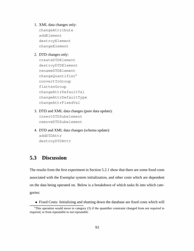
1. XML data changes only:
changeAttribute
addElement
destroyElement
changeElement
2. DTD changes only:
createDTDElement
destroyDTDElement
renameDTDElement
changeQuantifier1
convertToGroup
flattenGroup
changeAttrDefaultVal
changeAttrDefaultType
changeAttrFixedVal
3. DTD and XML data changes (pure data update):
insertDTDSubelement
removeDTDSubelement
4. DTD and XML data changes (schema update):
addDTDAttr
destroyDTDAttr
5.3 Discussion
The results from the first experiment in Section 5.2.1 show that there are some fixed costs
associated with the Exemplar system initialization, and other costs which are dependent
on the data being operated on. Below is a breakdown of which tasks fit into which cate-
gories:
) Fixed Costs: Initializing and shutting down the database are fixed costs which will1This operation would move to category (3) if the quantifier constraint changed from not required to
required, or from repeatable to not repeatable.
93

be incurred each time Exemplar is run. These costs are approximately 1.5 and 0.5
seconds respectively.
) DTD Related Costs: Creating the system dictionary classes is dependent on the
number of element, group, and attribute definitions in the DTD, plus the number
of quantifiers applied to elements and groups, because we create instances of the
system dictionary objects for each of these DTD items. Typically, the largest of
these costs is associated with the number of element definitions in the DTD, since
this number tends to overwhelm the others. If we divide the time to create the
system dictionary objects by the number of element definitions in the DTD, we find
this cost to be approximately 1.5 seconds per element. Generating the application
classes is also dependent on the number of element and attribute definitions in the
DTD(s), with the number of elements again being the dominant factor. We create
a new Java file for each element definition, and add a member variable to that file
for each attribute definition. When we divide the time to generate the application
classes by the number of element definitions in the DTD, we find this cost to be
approximately 2 seconds per element.
) XML Data Related Costs: Loading and dumping the XML data is obviously depen-
dent on the number of XML files to process and the number of instances of each
element in the data files. These costs per element are approximately 1.85 and 1.65
milliseconds respectively.
In our experiments we start each test from scratch, creating a new database, system
dictionary and application classes, and loading the data fresh each time. We also dump
out new XML files for the entire database each time a change is made, regardless of
what changed. In practical use, however, the Exemplar system need not be used in this
manner. The majority of the costs listed above might only be incurred once, because after
the database, system dictionary and application classes are created, Exemplar may be run
94

as many times as desired, executing various primitive operations to make changes to the
DTD/schema and/or data. In this more realistic scenario, the main cost which remains
a factor for each such Exemplar run is only the time to execute the primitive operations.
Dumping out new XML files after changes have been made also remains a factor, but this
can be done more discriminately, based on those files which have actually changed.
The results from the experiments in Sections 5.2.2 and 5.2.3 show, as expected, that
the total primitive execution times increase as the amount of data to process increases,
but that the individual operations are performed in a fixed amount of time when viewed
on a per-object basis. And finally, the results from our last experiment in Section 5.2.4
show that the amount of time to execute any given primitive varies, depending on the
data on which the operation is performed, and depending on the activities involved in
the particular operation. Although the addDTDAttr and destroyDTDAttr schema evolu-
tion primitives are the least efficient of the lot, the reasons for this are well understood
(described in Section 4.6.2), and otherwise the remaining primitive operations are very
efficient time-wise, considering the amount of work that may be performed. Based on
these results from our experimental study, we conclude that the Exemplar system would
prove useful to anyone desiring to maintain DTD and XML data which evolves over time,
as it automates changes which would otherwise need to be accomplished by hand, ensures
that changes are consistency preserving, and avoids having to reload data with each and
every change.
95

Chapter 6
Related Work
6.1 XML Management Tools
Since XML is primarily used as a data exchange format on the World Wide Web, many
research projects dealing with XML have focused on web site management [MMA99,
DFS99, FFK�
97, CCR00]. These projects attempt to alleviate difficulties associated with
managing large amounts of data contained in web sites by representing web pages as
XML documents. Although our XEM work does not focus on web site management,
research into these projects proved useful in understanding storage and manipulation of
XML documents.
Other research on XML focuses on its semi-structured nature [CAW98, Cha99, FS00].
In dealing with semi-structured data, some projects either totally ignore the schema, or
just consider it implicated by the actual storage structure and hence to be a “second-class”
citizen. They therefore do not deal with schema evolution issues. For example, Object
Exchange Model [PMW95] represents semi-structured data, similar in nature to XML,
without any associated DTD definition. DOEM [CAW98] is further proposed as a model
to represent changes in semi-structured data via temporal annotations. However, it only
96
deals with the changes at the data level and is schema-blind. All versions of a data item
will be stored together over time. Hence it results in an ever-growing complex annotated
data structure.
Finally, some XML tools have focused on various language formats as a mechanism
for manipulating XML data. For example, Extensible Stylesheet Language Transforma-
tions (XSLT) [Gro] is a language designed for transforming individual XML documents.
It does not require any DTD and users can specify arbitrary XML data transformation
rules. Hence no schema constraints are enforced on the data or on the transformation.
Lexus (XML Update Language) [Inf00] is a declarative language proposed by an open
source group, Infozone, to update stored documents. However, its primitives also only
work on the document level without taking the DTD into account. So neither XSLT nor
Lexus can serve in scenarios where a schema or structure is required.
6.2 Schema Evolution
Many database projects have focused on the issue of schema evolution [BKKK87, BMO�
89,
SZ86, CAW98, Zic91], where the main goal is to develop mechanisms to change not
only the schema but also the underlying objects such that they conform to the modified
schema. This issue was therefore a high priority in our XEM project. Most commer-
cial database systems today [Inc93, Tec94, Obj93, Tec92] provide support for the re-
structuring of the application schema by means of a fixed set of simple evolution primi-
tives, as does our XEM system. One issue which sets our project apart however, is that we
deal with constraints and invariants in order to preserve system integrity during schema
evolution. Recent work has been done to focus on the issues of supporting more com-
plex schema evolution operations [Bre96, Ler96]. These allow the user to string together
several primitives to form higher level yet still specific change transformations. Finally,
97

SERF [CJR98b, CJR98a] is a template-based, extensible schema evolution framework
that allows complex user-defined schema transformations in a flexible yet secure fashion.
6.3 XML and Database Systems
A number of projects and tools have emerged to map XML and similar semi-structured
data formats to traditional database systems. [FK99] looks at storing and querying XML
data using a relational database management system (RDBMS). Both [Koe99] and [MAG�
97]
investigate semi-structured data in relational databases, while [CACS94] looks at SGML
(the predecessor of XML) storage in an object-oriented database management system
(OODBMS). Oracle’s XML SQL Utility (XSU) [Net00] and IBM’s DB2 XML Extender
[IBM00a] are well-known commercial relational database products extended with XML
support. They mainly provide two methods to manage XML data. The first option is to
store XML data as a blob while the second option is to decompose XML data to relational
instances. However, if there is any update to the external XML data, for the first storage
option, they need to reload the data, and for the second option, they have to first figure out
and then make the change on the relational schema level. In other words, the evolution
of the data inside or outside of the database are independent from each other. Hence the
change propagation from an external XML document to its internal relational storage or
schematic structure is not supported. In a related effort at WPI, we have developed the
Clock system [ZMLR01] that synchronizes internal relational storage with external XML
documents, but this system deals with basic data updates only and does not handle schema
changes.
98

Chapter 7
Conclusions
7.1 Future Work
During the course of our research on the XEM project, a number of issues arose which
we did not have time to address. Here we present a number of new research directions
which could be undertaken to continue this work.
) XML Schemas: The format of an XML Schema includes more powerful features
for defining the structure and content of an XML document than a DTD. Our XEM
mapping model is currently tied to DTD format, but could be updated to handle
XML Schemas instead.
) Model Mapping: Our Exemplar implementation is currently tied to the PSE Object
Store database. A more generic model mapping, including a database-independent
layer, with database-specific drivers would be a more flexible solution.
) Versioning: If the Exemplar system were modified such that changes were made to
a new copy of DTDs and XML documents, rather than “in place”, or if deltas were
stored which could be applied to old documents to produce new ones, our system
99
could be used to provide revision control and version management services.
) Scripting: Currently, calling a primitive in our Exemplar system requires writing
Java code, since the primitives are implemented as methods. If we integrated a
scripting language into XEM, such as an XML query language like XQL [RLS98]
for example, then the user could easily combine primitives into more complex trans-
formations, as most scripting languages are simpler than programming languages.
) Evolution Templates: Once we have some form of scripting language in place,
then parameterized evolution templates could be introduced, similar to those pro-
vided by SERF [CJR98b]. These would give XEM more powerful functionality as
users could develop templates for commonly used complex transformations, which
are flexible and reusable because their specific behavior in a given circumstance is
allowed to vary based on parameters.
) Web Site Management: A screen scraping facility which produces XML from
HTML would allow us to integrate XEM into a web site restructuring tool, where
XML documents represent web pages, and XEM can be used to manage the com-
plexity of data on a web site, since our system is already capable of producing
HTML as output via XSLT stylesheets [Gro].
) Other Applications: In any environment where data is stored in XML format,
applications could be built on top of XEM to provide various data management
services. For example, in an environment where DTDs and XML documents are
stored in a repository such as Arbortext’s Epic [Arb00], an XEM application could
be used to manage changes to that data.
100
7.2 Summary
In this thesis, we present the first of its kind - a taxonomy of XML evolution operations.
Using pre- and post-conditions, these primitives assure the integrity of an XML data man-
agement system, both when DTD changes are made and XML documents have to change
to maintain consistency with the new DTD; and also when individual XML documents
are changed to ensure that the changed documents still conform to the corresponding
DTD. Our research into XEM is generic for XML data management, independent of any
specific implementation.
In our work on the XEM project, we make a number of important contributions in
the area of XML data management, including the first approach for addressing evolution
in an XML context. We show the motivation behind the need for such support, while
identifying the lack of existing support in current XML data management systems. We
propose a taxonomy of XML evolution primitives which includes both schema and data
updates to fill this gap. We identify various forms of system integrity which a sound XML
management system must maintain during evolution. These include the well-formedness
of DTDs and XML documents, which must conform to the standard language format;
the consistency of XML documents in terms of their invariants; and the validity of XML
documents with respect to the constraints specified in the corresponding DTD. We show
that our proposed change taxonomy is complete in that all valid desired transformations
are possible using our primitives, and sound in its maintenance of system integrity.
We prove the feasibility of our approach via the functioning Exemplar prototype im-
plementation using the Java programming language and an underlying object-oriented
database, and we describe in this thesis the important aspects of that implementation. We
conduct experimental studies to verify correct execution of the primitive operations within
our prototype system, and present a performance analysis in the form of results from our
101

experiments. These results show that our prototype indeed provides automated XML evo-
lution management facilities which are superior to making manual edits and then having
to reload data from scratch, which would be necessary using other current XML manage-
ment tools. We conclude that our research into XEM was a fruitful endeavor, with many
beneficial contributions to the field of XML data management as a result.
102

Bibliography
[ALP91] J. Andany, M. Leonard, and C. Palisser. Management of schema evolution indatabases. In VLDB, pages 161–170, September 1991.
[Arb00] Arbortext. Epic E-Content Engine: http://www.arbortext.com/Products/Epic/epic.html,November 2000.
[BKKK87] J. Banerjee, W. Kim, H. J. Kim, and H. F. Korth. Semantics and Implemen-tation of Schema Evolution in Object-Oriented Databases. SIGMOD, pages311–322, 1987.
[BL89] T. Berners-Lee. Information management: A proposal.http://www.w3.org/History/1989/proposal.html, March 1989.
[BMO�
89] R. Bretl, D. Maier, A. Otis, J. Penney, B. Schuchardt, J. Stein, E. H. Williams,and M. Williams. The GemStone Data Management System. In Object-Oriented Concepts, Databases and Applications, pages 283–308. ACM Press,1989.
[Bos] J. Bosak. Shakespeare’s Plays in XML Format, v2.00.http://metalab.unc.edu/bosak/xml/eg/shaks200.zip.
[Bre96] P. Breche. Advanced Primitives for Changing Schemas of Object Databases.In CAISE, pages 476–495, 1996.
[CACS94] V. Christophides, S. Abiteboul, S. Cluet, and M. Scholl. From StructuredDocuments to Novel Query Facilities. In Proceedings of the ACM SIGMODInternational Conference on Management of Data, Minneapolis, pages 313–324, June 1994.
[CAW98] S. Chawathe, S. Abiteboul, and J. Widom. Representing and QueryingChanges in Semistructured Data. In ICDE, pages 4–13, February 1998.
[CCR00] L. Chen, K. T. Claypool, and E. A. Rundensteiner. SERFing the Web: TheRe-Web Approach for Web Re-Structuring. WWW Journal - Special Issue onInternet Data Management, Baltzer/ACM Publication, 2(1):33, 2000.
103

[Cha99] S. Chawathe. Describing and Manipulating XML Data. In IEEE Data Engi-neering Bulletin 22(3), pages 3–9, 1999.
[CJR98a] K.T. Claypool, J. Jin, and E.A. Rundensteiner. OQL SERF: An ODMG Im-plementation of the Template-Based Schema Evolution Framework. In Centrefor Advanced Studies Conference, pages 108–122, November 1998.
[CJR98b] K.T. Claypool, J. Jin, and E.A. Rundensteiner. SERF: Schema Evolutionthrough an Extensible, Re-usable and Flexible Framework. In Int. Conf. onInformation and Knowledge Management, pages 314–321, November 1998.
[DFS99] A. Deutsch, M.F. Fernandez, and D. Suciu. Storing Semistructured Data withSTORED. In Proceedings of ACM SIGMOD International Conference onManagement of Data, pages 431–442, Philadephia, USA, June 1999.
[FFK�
97] M. Fernandez, D. Florescu, J. Kang, A. Levy, and D. Suciu. System Demon-stration - Strudel: A Web-site Management System. In ACM SIGMOD Con-ference on Management of Data, pages 549–552, 1997.
[FK99] D. Florescu and D. Kossmann. Storing and Querying XML Data using anRDBMS. In IEEE Data Engineering Bulletin, pages 27–34, 1999.
[FS00] W. Fan and J. Simon. Integrity constraints for XML. In In Proceedings ofthe Nineteenth ACM Symposium on Principles of Database Systems, pages23–34. ACM Press, 2000.
[Gol91] C. F. Goldfarb. The SGML Handbook. IBM Almaden Research Center, SanJose, California, 1991.
[Gro] W3C XSL Working Group. XSL Transformations (XSLT).http://www.w3.org/TR/xslt/.
[IBM00a] IBM Software. DB2 XML Extender. http://www-4.ibm.com, 2000.
[IBM00b] IBM Software. XML Parser for Java:http://www.alphaworks.ibm.com/aw.nsf/techmain/xml4j, 2000.
[Inc93] Itasca Systems Inc. Itasca Systems Technical Report. Technical Report TM-92-001, OODBMS Feature Checklist. Rev 1.1, Itasca Systems, Inc., Decem-ber 1993.
[Inf00] Infozone Group. Lexus. http://www.infozone-group.org/lexusDocs/html/wd-lexus.html, 2000.
[Koe99] A. Koeller. Semi-Structured Data in Relational Databases. Technical report,Worcester Polytechnic Institute, 1999.
104

[KSC�
01] D. Kramer, H. Su, K. T. Claypool, L. Chen, K. Oenoki, and B. Liu. XML Evo-lution Management Prototype System: http://davis.wpi.edu/dsrg/xem/code,2001.
[LB98] S. Liang and G. Bracha. Dynamic Class Loading in the Java Virtual Machine.In OOPSLA, pages 36–44, October 1998.
[LC00] D. Lee and W. Chu. Constraints-Preserving Transformation from XML Doc-ument Type Definition to Relational Schema. In Proceedings of the 19th In-ternational Conference on Conceptual Modeling (ER2000), pages 323–338,2000.
[Ler96] B.S. Lerner. A Model for Compound Type Changes Encountered in SchemaEvolution. Technical Report UM-CS-96-044, University of Massachusetts,Amherst, Computer Science Department, 1996.
[Ler00] B.S. Lerner. A Model for Compound Type Changes Encountered in SchemaEvolution. ACM Transactions on Database Systems, 25(1):83–127, 2000.
[LMZ00] W. Lee, G. Mitchell, and X. Zhang. Metadata-Driven Approach to IntegratingXML and Relational Data. In Technical Report, GTE Labs, Waltham, MA,2000.
[MAG�
97] J. McHugh, S. Abiteboul, R. Goldman, D. Quass, and J. Widom. Lore: ADatabase Management System for Semistructured Data. In SIGMOD Record26(3), pages 54–66, September 1997.
[MMA99] G. Mecca, P. Merialdo, and P. Atzeni. Araneus in the era of xml. In Bulletinof the Technical Committee on Data Engineering, pages 19–26, September1999.
[Net00] Oracle Technologies Network. Oracle8i.http://www.oracle.com/database/oracle8i, 2000.
[Obj93] ObjectStore, Inc. ObjectStore Manual, 1993.
[Obj99] Object Design. Excelon Data Integration Server.http://www.odi.com/excelon, 1999.
[PMW95] Y. Papakonstantinou, H. Garcia Molina, and J. Widom. Object Exchangeacross Heterogeneous Information Sources. In Proceedings of the 11th Inter-national Conference on Data Engineering, Taipei, Taiwan, pages 251–260,March 1995.
[RCC�
00] E. A. Rundensteiner, K. T. Claypool, L. Chen, H. Su, and K. Onoeki. SERF-ing the Web: A Comprehensive Approach for Web Site Management. InSIGMOD, page 585, May 2000.
105

[RLS98] J. Robie, J. Lapp, and D. Schach. XML Query Language (XQL).http://www.w3.org/TandS/QL/QL98/pp/xql.html, September 1998.
[Sjo93] D. Sjoberg. Quantifying Schema Evolution. Information and Software Tech-nology, 35(1):35–54, January 1993.
[SKC�
01] H. Su, D. Kramer, L. Chen, K. T. Claypool, and E. A. Rundensteiner. XEM:Managing the Evolution of XML Documents. In Eleventh International Work-shop on Research Issues in Data Engineering (RIDE), Heidelberg, Germany,pages 103–110. IEEE Computer Society, April 2001.
[Sun00] Sun Microsystems. Java 2 SDK, Standard Edition, v1.3:http://www.javasoft.com/j2se/1.3/, May 2000.
[SZ86] A. H. Skarra and S. B. Zdonik. The Management of Changing Types in anObject-Oriented Databases. In Proc. 1st OOPSLA, pages 483–494, 1986.
[Tec92] Versant Object Technology. Versant User Manual. Versant Object Technol-ogy, 1992.
[Tec94] O + Technology. O + Reference Manual, Version 4.5. O + Technology, Ver-sailles, France, November 1994.
[W3C98] W3C. Extensible Markup Language (XML) 1.0 – W3C Recommendation 10-February-1998. http://www.w3.org/TR/REC-xml, 1998.
[W3C99] W3C. XML Path Language (XPath) Version 1.0.http://www.w3.org/TR/xpath, 1999.
[W3C00] W3C. Extensible Markup Language (XML) 1.0, 2nd Edition – W3C Recom-mendation 6-October-2000. http://www.w3.org/TR/REC-xml, 2000.
[W3C01a] W3C. XML Query Data Model – W3C Working Draft, 15-February-2001.http://www.w3.org/TR/query-datamodel, 2001.
[W3C01b] W3C. XML Schema – W3C Proposed Recommendation 2001-03-16.http://www.w3.org/XML/Schema, 2001.
[Zic91] R. Zicari. A Framework for O + Schema Updates. In 7th IEEE Int. Conf. onData Engineering, pages 146–182, April 1991.
[ZMLR01] X. Zhang, G. Mitchell, W. Lee, and E. A. Rundensteiner. Clock: Synchroniz-ing Internal Relational Storage with External XML Documents. In EleventhInternational Workshop on Research Issues in Data Engineering (RIDE), Hei-delberg, Germany, pages 111–118. IEEE Computer Society, April 2001.
106