wood turning - forgotten books
TRANSCRIPT

WO O D T UR N I N G
PREPARED FO R T H E U SE OF STUDEN T S IN MAN UAL TRA IN IN G
H IG H SC H O O LS ,TEC H N ICAL SC H O O LS ,
AN D CO LLEG ES
G EO R G E ALEXA N DE R RO S SI N STRU CTOR I N \VO O D \VO RK A N D PA TTE R N MAK I NG , L E \V I S I N ST ITUTE , C H ICA G O
G I N N A N D CO MPA N Y
B’
O STO N N EW Y O R K C H ICA G O LO N DO N

CO PY R I G H T, 1909, BY
G EORG E ALEXAN DER RO S S
ALL R I G H TS R E S E RV E D
m l) : g t b z u c um b u s s
G INN AN D COMPANY PR O
PR IETOR S BOSTON U . S .A .

PR EFAC E
The obj ect of th ese p ag es is to p lace befo r e pupils such information as wil l be
of practical help to th em in their work in wood turn ing .
I t has been the writer’s experience that pupils lose confidence and becom e
nervous because of the mishaps that are sure to occur,especially in attem pting
certain form s often presented early in courses of th is character ; and for th is reason
these exercises have been arranged in such a way that the turning of beads and
sim ilar work is left unti l such time as the confi dence of the pupil i s fully establ ished ;i n fact
,until he has had considerable experience on the lathe in handl ing the prin
cip al tools in connection with the s impler forms .
The course and problems are those which pupils in elementary woodwork at the
Lewis I nstitute are required to complete during the first course in shop work,and
are so arranged that each successive lesson contains a new principle closely related
to those in previous exercises .
The book is intended for class work,and
,as stated elsewhere in th is volume
,
should be supplemented by instructions and demonstrations given by an instructor
in charge .
This l ittl e work is sent out with the hope that it may prove of practical benefi t
to those into whose hands it may come .
G E OR G E ALEXAN DE R RO S S
LEW I S I N ST ITUTEC H ICAGO , I LL I NO I S

CO N T E N T S
I N TRODUCTORY TEXT
PR IM IT IV E LATH E S A N D THE I R D EV E LO PM ENTT H E S PEED LATH E A N D I T S PA RTS .
T H E RULE S FO R OBTA I N I NG T H E D IAM ETE RS A N D S PEEDS PULLE Y SMOTO R H EAD A N D G A P LATHE STOOLS U S ED I N TU RN I NGG R I ND I NG A N D SHA RPEN I NG TURN I NG TOOL ST H E G OUGE
T H E S KEW C H I S E LT H E ROUND -N O S E S C RA P I N G TU RN I N G TOOLT H E S " UA RE -N O S E S C RA P I NG TOOLT H E D IAMOND - PO I NT TOO LT H E C UT -O FF O R PA RT I NG TOO LT H E S I Z I NG TOOLTOOLS U S ED FO R MEAS U R I NG
TOOL S U S ED FO R S H A R PEN I NG .
S I Z E S O F C H I S E LS A N D G O U G IZS
LAT H E~T O O L PRACT I CE
I . C Y L I NDE RI I . CY L I NDE R , S TE P PEDI I I . S OCKET C H I S E L H ANDLEIV . TEA POT S TANDV . C A NDLEST ICKV I . MA LLETV I I . C ANDLEST ICKV I I I . N APK I N R I NGSI X . S MALL B o xX . S MOKE RS ’
S ET
X I . TOWE L RA I LS .
X I I . ROLL I NG P I N
X I I I . POTATO MASHE R
XIV . CARD R ECE IVER .

vi WOOD TURNING
S UPPLEME N TARY E XERC I SE S PAG EPOL ICEMAN ’
S C LU B (Fi g . 74 )
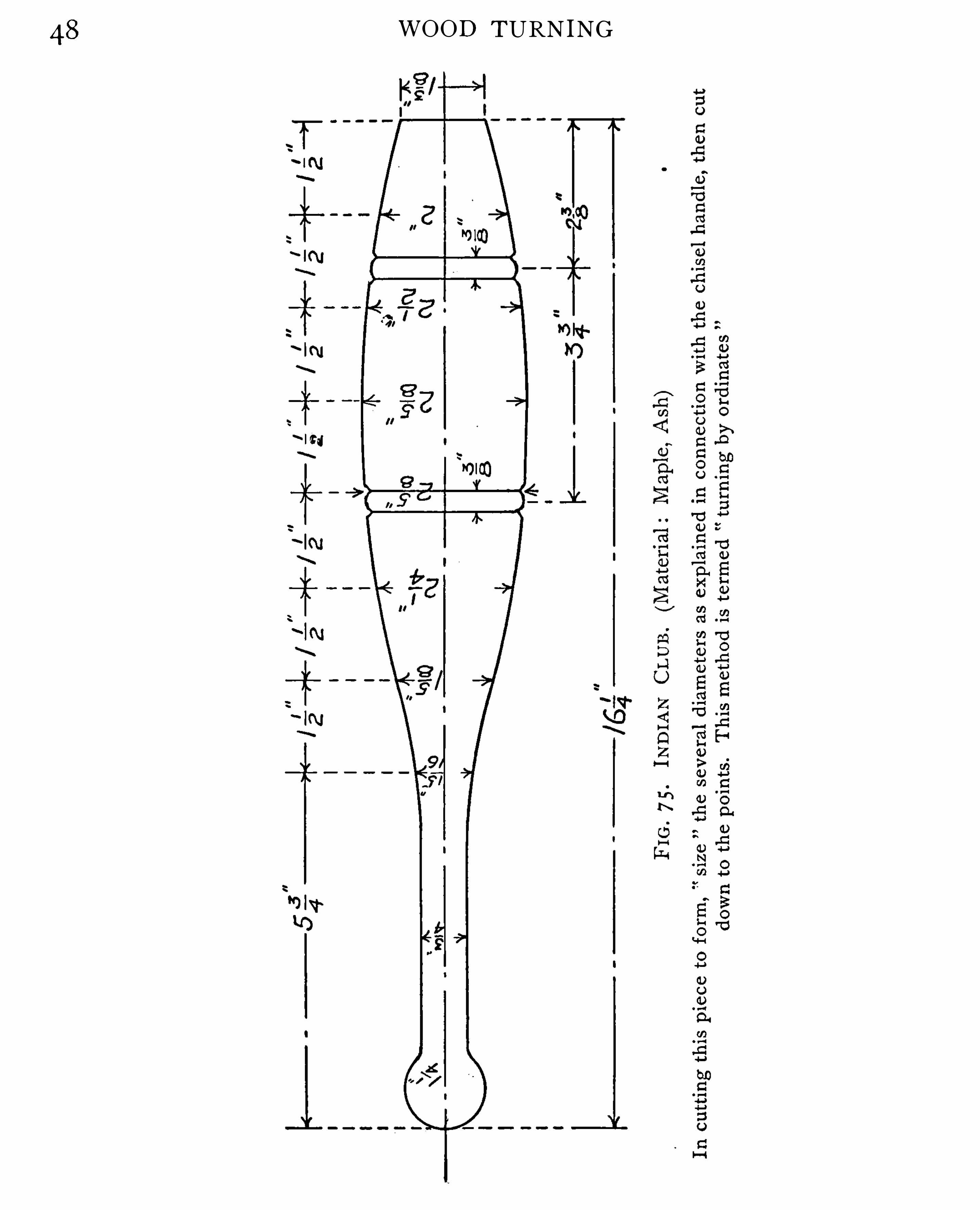
I ND IAN C LUB (Fi g . 7 5 )
BOW L (Fi g . 76)
PLATE (FI G . 7 7 )
P ICTU RE FRAM E (Fi g .
POW DE R B o x (Fi g . 79 )
C UP (Fi g . 80 )
DUM B - B ELL (Fi g . S I )
G AV EL (Fi g . 82 )
TU RN I NG TOOL H A NDLE S (Fi g . 83 )
TOW EL R I NGS (Fi g . S4 )
VAS E (Fi g . 8 5 )
LAM P S TANDA RD (Fi g . S6 )
S TOCK I NG AN D G LOV E DA RN E R (Fi g . 87 )
PA RTED O R S PL IT WO RK (Figs . 88 . 89 , 90 ,
M I SCE LLAN E OUS TURN E D MO LD I N G S
PLATES I—V I
APPE N D IX
FI N I SH ESFI LLE RSS TA I N S
A N I L I NE S TA I N SM ISCELLAN EOU S REC I PESC EM ENT U S ED I N TU RN I NGMETHOD S O F RE F I N I SH I NG VA RN I S HED S U R FACES
I N DE X
W O O D T UR N IN G
The art of turn ing is one of the most anc ient of the han dicrafts,and is as
important as it is anc ient . The m ach ine on which the w ork is pe r formed is cal led
a lathe .
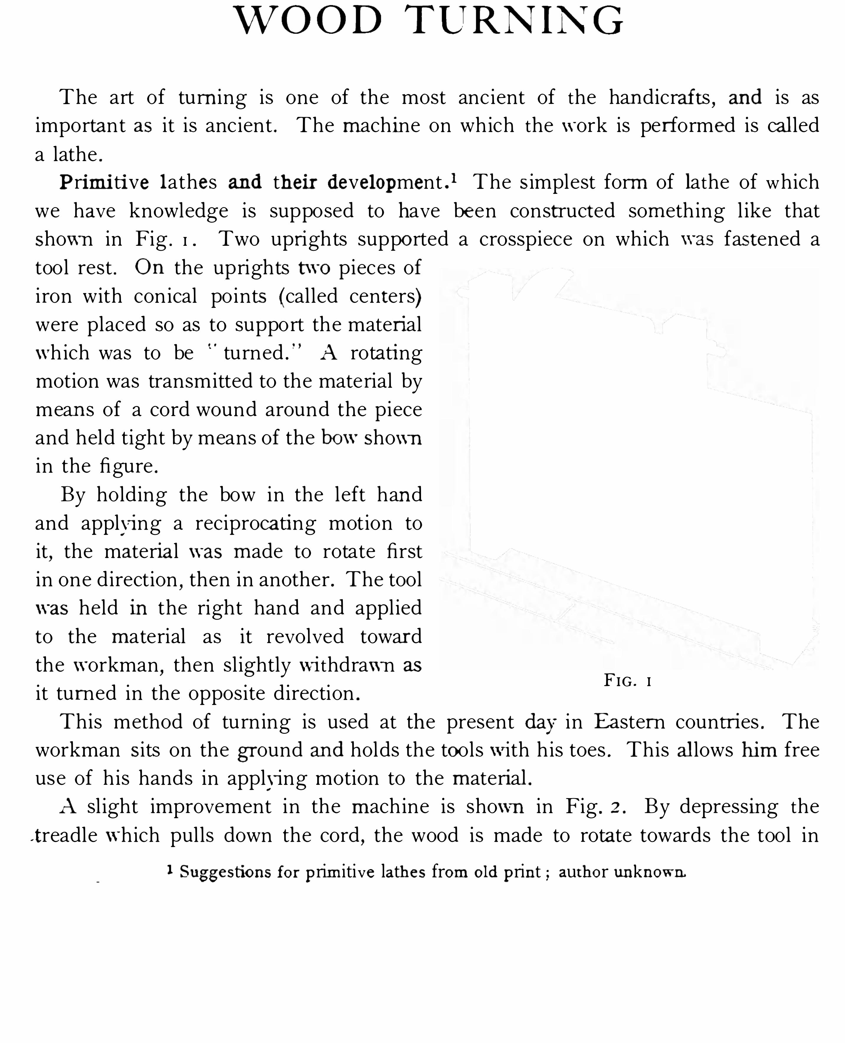
P ri m i ti ve lathes and th ei r develo pment ) The S implest form of lathe of which
we have knowledge is supposed to have been constructed som eth ing l ike that
Show n in Fig . I . Two upr ights suppo rted a crosspiece on which fastened a
tool rest . O n the uprights t wo pieces of
i ron with con ical po ints (called centers)were placed so as to support the materi al
w h ich was to be turned . A rotati ng
motion was transmitted to the material by
mean s of a cord wound around the piece
and held tight by means of the bo w Shown
in the figure .
By holding the bow in the left hand
and applyi ng a reciproca ti ng motion to
it,the materia l w as m ade to rotate first
in one direction,then in another . The tool
w as held in the right hand and appl ied
to the m aterial as it revolved towar d
the w orkman,then sl ightly wi thdraw n as
it tu r ned in the opposite direction .
This method of tu rn ing is used at the present day in Ea ster n countri es . The
workman S its on the g r ound and holds the to ols w ith h is toes . This al lows h i m free
use of h is hands in apply ing motion to the m aterial .
A sl ight improvement in the m ach ine is shown in Fig . 2 . By depress ing the
t readle w hich pul ls down the cord,the wood is made to rotate towards the tool in
FIG . I
1 S ug g esti o ns fo r p rim itive lath es fro m o ld p rint aut h o r unkno w n

2 WOOD TURNING
FIG .
'
2 FIG . 3
the direction in which the cutting is done and when the pressure is removed,the
elastic ity of the bow pulls the cord and treadle upward,ready to be depressed
the operator’s foot . W ith th i s arrange
ment the operator was able to stand at
h is work,li sm g his foot to give the arti
cle motion,thus allowing h im the use of
both hands to m anipulate the tools .
I n both the mach ines shown the dr iv
ing cord was wound around the work
itself . This made it necessary that the
m aterial be much longer than the article
to be turned . Moreover,in such a m achine
there would be danger of breaking the
wood ( if it were smal l and slender) by the
continued up-and- down pull of the cord .
Another step in the improvement of the
lathe is shown in Fig . 3 . The inco nvenience aris ing when the -cord was wound around the work doubtless led to the
appl ication of the pulley to rotate th e material . The principle is the same as in
FI G . 4
T H E S PEED LAT H E AN D IT S PART S 3
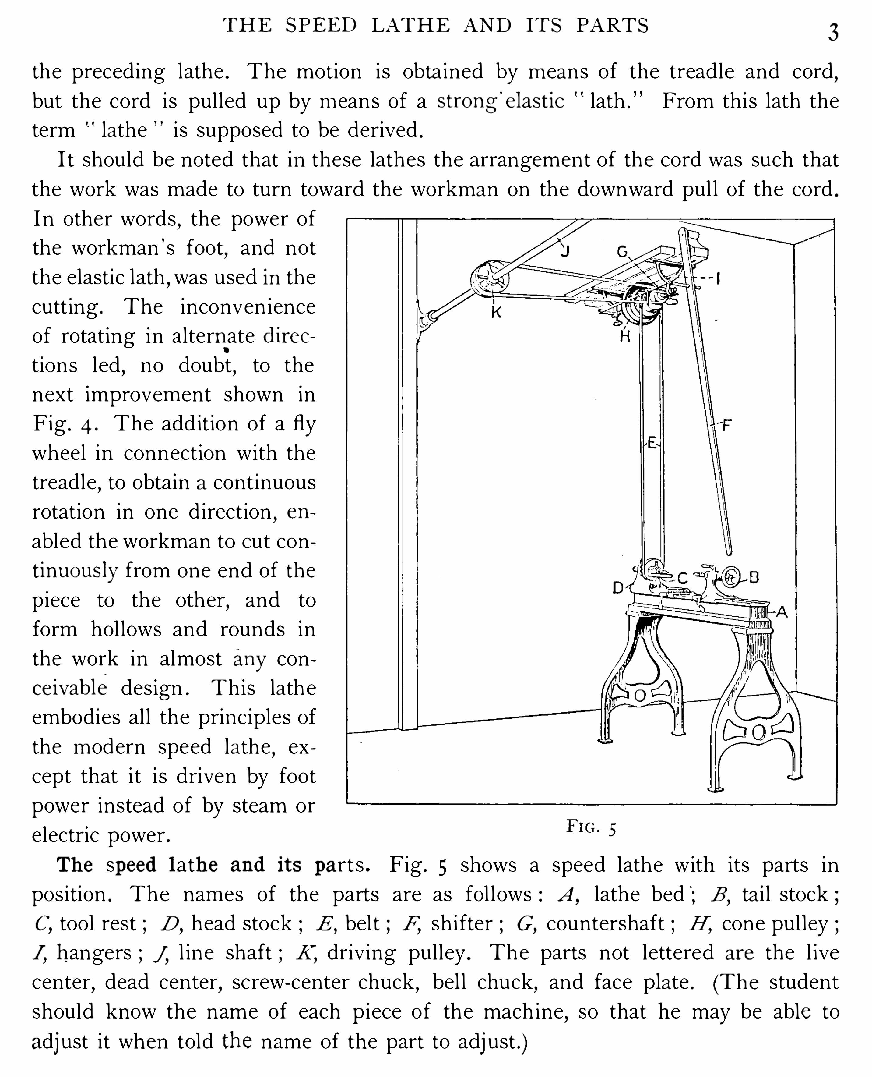
the preceding lathe . The motion is obta ined by m eans of the treadle and cord,
but the cord is pul led up by m eans of a str o ng’
elast ic lath . From this lath the
term lathe is supposed to be derived .
I t should be noted that in these lathes the arrangement of the cord was such that
the work was made to turn toward the workm an on the downward pul l of the cord .
I n other words,the power of
the workman ’s foot,and not
the elastic lath,was used in the
cutting . The inconvenience
of rotating in alternate d i r ec
tions led,no doubt
,to the
next improvem ent shown in
Fig . 4 . The add ition of a fly
wheel in connection with the
treadle,to obtain a continuous
rotation in one direction,en
abled the workman to cut con
t inuo usly from one end of the
piece to the other,and to
form hol lows and rounds in
the work in almost any con
ceivab le design . T his lathe
embodies al l the principles of
the m odern speed lathe,ex
cept that it i s driven by foot
power instead of by steam or
electric power .
Th e sp eed lath e and i ts p arts . Fig . 5 shows a speed lathe with its parts in
position . The nam es of the parts are as fol lows : A,lathe bed B
,ta i l stock ;
C, tool rest ; D ,head stock ; E ,
belt ; F,shifter ; G ,
countershaft ; H ,cone pul ley ;
I, h angers ; j , l ine shaft ; K,
driving pulley . The parts not lettered ar e the l ive
center,dead center
,screw- center chuck
,bell chuck
,and face plate . (T h e student
should know the name of each piece of the mach ine,so that he may be able to
adjust it when told th e name of the part to adjust . )

4 WOOD TURNING
Tfie keaa’sto ck . A close study of the head stock (Fig . 6 ) will show that it is
made up of several parts, the larg est piece of wh ich i s the main casting A ,into
which bearings B are fi tted . I n the bearings the spindle revolves . I t wil l
FIG . 6
be noti ced that the spindle i s hollow . This allows for the removal of the l ive
center D,when the bel l chuck A
,screw center B
,or face plate C (Fig . 7 ) are to be
used . The l ive center i s removed by a rod inserted at the left—hand end . The face
plate and chucks are screwed on to the Spindle .
The cone pulley E (Fig . 6 ) is fastened to the spindle by pins or screws , and the
adj usting mechanism F adj usts the Spindle for end thrust,so that when face plate
FIG . 7
or chucks are used there will be no lateral motion to the work . The oil cups, or
holes,are on top of the bearings . The bearings should be oiled frequently to avoid
hot boxes .
Tlze ta i l stock . The tail stock also (Fig . 8 ) is made up of several parts , a thor
oug h understand ing of whose functions will save much trouble . I n some lathes

T H E S PEED LAT H E AN D IT S PART S 5
the casting A is fastened to the bed by means of a clamp,and in others by m eans
of a hand wheel . This is placed underneath the bed in such a manner that when
the wheel is turned up on a screw provided for the purpose,the tail stock wil l be
fastened in any desirable position between the head stock and the end of the bed .
The tail- stock spindle B i s also hollow ,for two reasons : first
,to give the screw
C,which is in contact with the nut D
,room to pass beyond the nut in order to move
the spindle in and out of the tail stock . and,second
,to allow the dead center E to
be removed when necessary . I t wil l be observed that the end of the dead center
FIG . 8
proj ects a short distance into the chamber provided for the screw,so that when the
spindle is drawn into the tai l stock,the end of the screw comes into contact with
the end of the dead center . This forces the dead center out of its socket and per
m its the center to be rem oved without d ifficulty . I t wil l also be observed that if the
screw does not enter the nut, the spindle wil l remain stationary, no matter howmuch the screw may be turned . I n adj usting the tail stock
,therefore
,great care
should be exercised in turn ing out the spindle,so that the nut wil l not be moved
far enough to leave the screw . There is danger of bending the thread of the nut
or screw out of shape in trying to force the spindle back into position . S hould th is
be done,the damag e can be rep ai red only by taking th e whole tail stock apart .
6 WOOD TURNING
The hand wheel F is used to turn the screw in the spindle ; the clamp G i s used
to fasten the spindle in place when once set .
O n the s ide of the spindle is a slot (not shown in the figure) into wh ich the end
of a pin or screw proj ects,to prov ide against the spindle ’s turn ing when it is drawn
in or out of the ta i l stock .
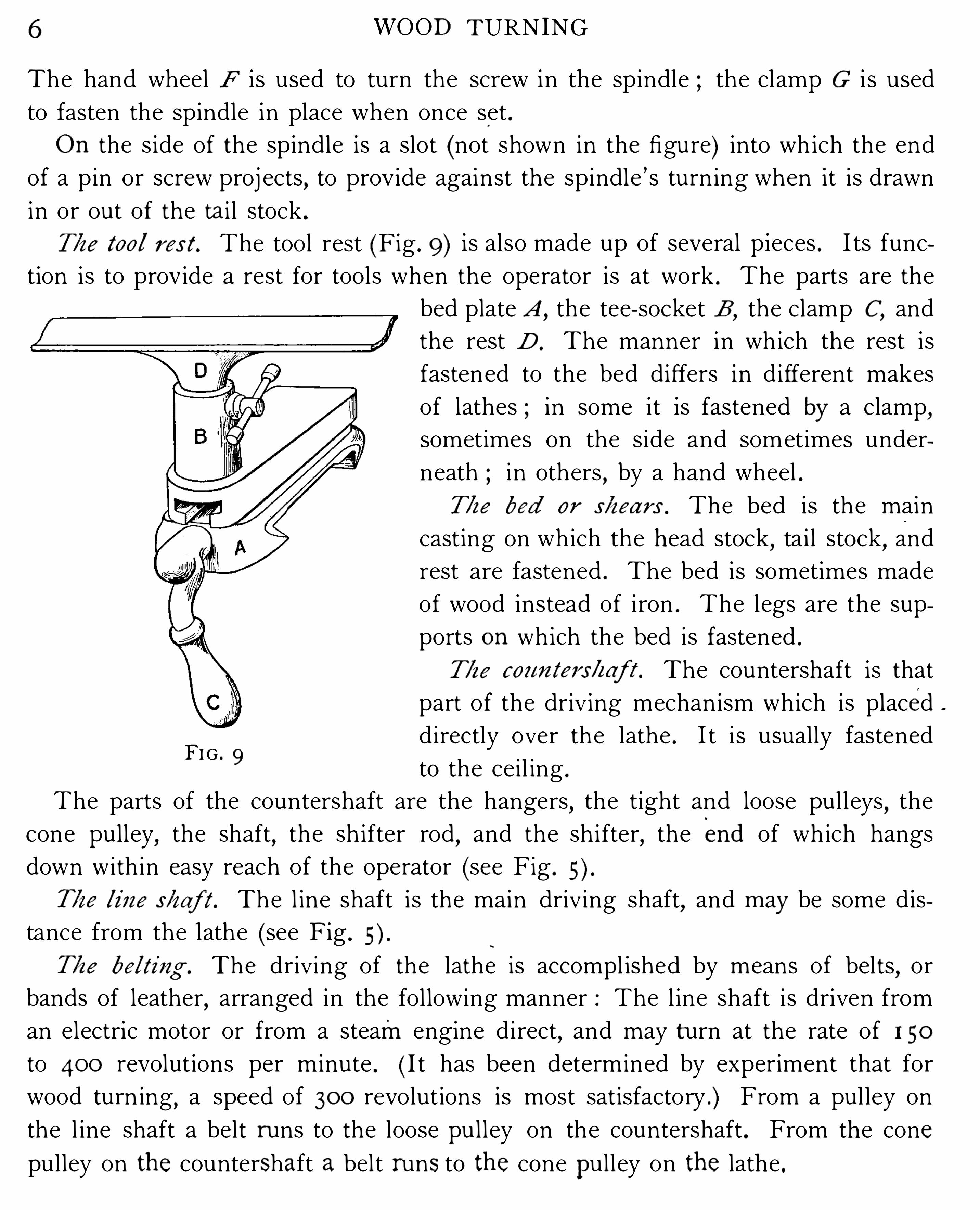
T/ze to o l r es t . The tool rest (Fig . 9 ) i s also made up of several pieces . I ts func
tion is to prov ide a rest for tools when the operator is at work . The parts are the
bed plate A,the tee- socket B
,the clamp C
,and
the rest D . The manner in which the rest is
fastened to the bed differs in different makes
of lathes ; in some it is fastened by a clamp,sometimes on the side and sometimes under
neath in others,by a hand wheel .
T/ze bed o r s/zea r s . The bed is the main
casting on which the head stock,tail stock
,and
rest are fastened . The bed is sometimes made
of wood instead of iron . The legs are the sup
ports o n which the bed is fastened .
T/ze COZ tflfef’S/zaff. The countershaft is that
part of the driving mechanism which is placed
directly over the lathe . I t i s usually fastened
to the ceil ing .
The parts of the countershaft are the hangers,the tight and loose pulleys
,the
cone pulley,the shaft
,the shifter rod
,and the shifter
,the end of which hangs
down within easy reach of the operator (see Fig .
7725 line s/zaf t . The l ine shaft is the main driving shaft, and m ay be some dis
tance from the lathe (see Fig .
T/ze belting . The driving of the lathe is accompl ished by means of belts,or
bands of leather,arranged in the following manner : The l ine shaft is driven from
an electric motor or from a steam engine direct,and may turn at the rate of I 50
to 400 revolutions per minute . ( I t has been determined by experiment that for
wood turn ing,a speed of 300 revolutions is most satisfactory .) From a pulley on
the l ine shaft a belt r uns to the loose pulley on the countershaft . From the cone
pulley on th e countershaft a belt r uns to th e cone p ulley on th e lathe .
FI G . 9

T H E D IAMET ERS AN D SPEEDS OF PULLEYS 7
When it is desired to have the cone pulley on the lathe revolve,the shifter is
moved to one side . This m ovement throws the belt over on to the tight pulley on
the countershaft,a nd th is
,in turn
,causes the cone pulley on the lathe to revolve .
T/ze g ea r ing of tb e la t/ze. By this term is m eant the sp eed at which the lathe is
belted to give the desired number of revolutions per m inute . I t wil l be observed
from Fig . 5 how this is accompl ished . O n the l ine shaft is a pul ley larger than
that on which the belt runs on the countershaft . This means that the counter
shaft m akes a greater num ber of revolutions than the l ine shaft,or
,in other words
,
the number of revolutions is increased by the belt running from a large pulley to a
sm al ler one .
Th e r ules fo r ob ta ining th e di am eter s and sp eeds of p ulley s ar e as fo llow s .
I . T/ze di am eter and num ber of r evela ti o ns of tb e d r iver and di am eter of tb e
dr iven being g iven to fi nd i ts num ber of r evb /nti o ns : Multiply the diameter of the
driver by the number of its revolutions,and d ivide the product by the diam eter of
the driven the quotient wil l be the number of revolutions of the driven .
2 . T/ze di am eter and r evo lu ti o ns of t/ze d r iver bei ng g i ven,to fi nd t/te d i am e
ter of t/ze d r iven t/za t s/za/i m ake any g iven num ber of r evo lt/ti o ns i n tb e sam e
ti m e : Multiply the diameter of the driver by its num ber of revoluti ons,and divide
the product by the number of revolutions of the driven ; the quotient wil l be
its diam eter .
3 . T0 ascer ta i n t/i e s i z e of tb e d r iver : Multiply the diam eter of the driven by
the number of revolutions you wish it to m ake,and divide the product by the revo
lutions of the driver ; the quotient wil l be the diameter of the driver .
The face of a pul ley for a no nsh ifting belt should be round or crown ing, and
for a shifting belt,straight . ( I n ordering p ulleys the exact siz e of the shaft on
which they are to go should be‘
given . )Mo to r h ead and g ap lath es . Before passing to tools and materials we m ay
mention the m otor head and gap lathes,
lathes that have appeared on them arket during the past few years .
The im provem ents shown in the speed lathe as compared with primitive types
have been siIcceeded by a self- conta ined lathe known as a motor-head lathe .
This type of lathe el iminates al l overhead transmission and belts,thus giv ing to a
shop a more pleasing appearance than belt-driven m achines ; also giving m ore
l ight, less dust, and no danger from breaking belts or countershafts .
8 WOOD TURNING
The lathes here shown are the product of the O l iver Machinery Com pany of
G rand Rapids , Michigan , and selected because they are the ones with which the
writer is most famil iar .
I n Fig . 9 A is shown a lathe , to drive which a belt is used .
A nother feature of th is machine i s the overhanging spindle,which is used for large
face-plate work . The lathes that follow are the latest designs of th is type of mach ine .
FIG . 9 A
I t will be observed from Fig . 10 that the lathe is practically the sam e in al l its
features as the Ordinary belted speed lathe,with the exception of the head stock or
motor head,the motor taking the place of the cone pulley and overhead m echanism .
This type of lathe is so arranged that fifteen different speeds are obta ined th is
m akes it a desirable machine in many ways . The starting box and switch fastened
on the left-hand end of the bed are with in easy reach of the operator,thus making
control of the machine a s imple matter .
MOTOR H EAD AN D G AP LAT H E S 9
FIG . 10
An im provement on the above lathe is Shown in Fig . I I,a hand feed and
compound swivel rest being features that ar e of great help in the production of
certa in kinds of work,especial ly in a pattern shop or brass- turn ing room .
Inth is lathe the tools are held rigid in the tool post,so that the man ipulation
in cutting is done by turn ing the hand wheels on the apron and cross feed .
I O WOOD TURNING
FI G . I I
I n Fig . I I A i s shown another ty pe of lathe which is a self- conta ined machine .
From a study of the figure it wil l be seen that the m otor has an extended armature
shaft on which a cone pulley is fastened . From th is cone pulley a bel t is run up
on to the cone in the head stock,thus el iminating the countershaft that is a feature
of belted lathes . When the belt is to be sh ifted, the motor is raised enough to
loosen the belt,so that it can be easily changed .
The switch block and rheostat are placed directly over the motor,thus in a meas
ure protecting the m otor from dust . The controll ing lever is shown j ust above the
switch,and is in easy reach of the operator
,giv ing perfect control of the machine .
The motor on this type of lathe is arranged for alternating current .


1 2 WOOD TURNING
FIG . I 2
w h il e the cross sl ide carries a graduated compound swivel rest, which can be set
at any angle . The value of th is in some kinds of work cannot be overestimated
when accuracy is required,and when the gap is open a piece of work eighty- s ix
inches in leng t h and sixty inches in d iameter can be turned . This gives some
idea of the capacity of a mach ine of th is kind .
The makers of th is mach ine claim many special features in construction,etc . ,
and pup il s studying it are referred to trade catalogues for data on lathes .
Lack of space compels us to omit a description of what are known as copying
lathes,also automatic back knife lathes . For descriptions of these mach ines the
pupil i s again referred to trade catalogues .
Too ls used in tur ning . I n turn ing,as in any process
,there is always more
than one way of doing a th ing,and it i s often d ifficult to decide on the best meth
ods of per forming special operations . O ne workman may perform a number of
operations with one tool , while another may use a tool for each operation .
The l ist of tools here given wil l be found satisfactory for ordinary wood
turn ing ; for work requiring spec ial Operations spec ial tools wil l be introduced
and explained .
M easu r ing to o ls a tw o -fo o t rule ; a p ai r o f o utside cal ip ers ; a p ai r o f inside cal ip ers ; a p ai ro f co m p asses.
S h a rp en i ng to o ls an o i lsto ne ; a sl ip sto ne ; a p iece o f leath er used as a stro p ; an o i l can .
Cutt i ng to o ls : o ne g - inch skew ch isel ; o ne i - inch skew ch isel ; o ne g - inch turning go uge ;o ne i - inch turning go uge ; one 95 - inch ro und-no se scrap ing to o l ; o ne g - inch square-no se scrap ingto o l ; o ne - inch diam o nd o r sp ear-p o int to o l ; o ne - inch cut- o ff o r p arting to o l .W o o d turners o ften use wh at i s known as a siz ing to o l . I t i s no t a necessi ty, but i t saves tim e
wh ere a num ber o f p ieces o f th e sam e diam eter ar e to be cut.A uxi l i a ry to o ls o ne wo o den m al let ; o ne center p unch .

GRINDING AN D S H ARPENING TURNING TOOLS I 3
Ext r a to o ls fo r g ener a l use o ne bi t brace ; o ne é -inch drill bi t ; o ne 93 -inch dril l bi t ; o nescrew-driver ; o ne m o nkey-wrench .
Befo re sh arp ening, to o ls ar e first gro und to th e co rrect sh ap e ei th er o n an em ery wh eel o r o n
a grindsto ne. H ence an em ery wh eel o r a grindsto ne is a necessary p art o f th e equipm ent .
G r inding and sh arp ening tur ning to o ls . The speeds at which grindstones revolve
vary for different kinds of work . For general tool grind ing,handbooks recom mend
that a stone travel between 300 and
600 feet per m inute . The writer’s
practice has been to have the grind
stone travel at about 42 5 feet per
m inute ; that is , a grindstone of 36
inches in diameter should make 4 5" G 1 3 revolutions per minute .
To determine the number of feet which the circumference of th is stone travels
per minute,m ultiply the diameter of the stone by the ratio 7 r that is
,
or I I 4 . Multiply th is product by the
number of revolutions (4 5 ) which the stone makes per minute
and div ide the result by 1 2°
U 4 X 4 52
.
1, ft .
1 24 7
To grind a tool the worker should take a position so that the
grindstone is revolv ing toward him,and should apply the tool to
the stone in such a m anner that the cutting edge of the tool wil l
not be inj ured by the grinding . The stone may also be used
revolving from the operator .
I n Fig . I 3 i s shown the m ethod to be followed . Place the tool
on the stone as shown by the dotted l ines ; then draw it back to
the position shown by the full l ines . The bevel wil l then be in
contact with the stone . Then,i f the tool be flat l ike a chisel
,move it from s ide to
side,as indicated by the arrow points in Fig . 1 8 . This appl ies to tools in general .
Th e g oug e. O f al l the tools used by the wood turner there is none more com
m o nly used than the gouge as the j ack plane is to the bench worker,so the gouge
is to the wood turner .
FIG . 14
14 w o o D TURNING
B efore grinding th i s tool,notice the shape it sho uld have . The end is ground in
an ell iptical form,the bevel being practical ly a straight l ine
,as shown at AB
,Fig . I 4 .
To grind"
the gouge,apply it to the
grindstone,fo l lowing the general rule
given ; then slowly rotate it from side
to side until the end is the desired shape
(see Fig . I
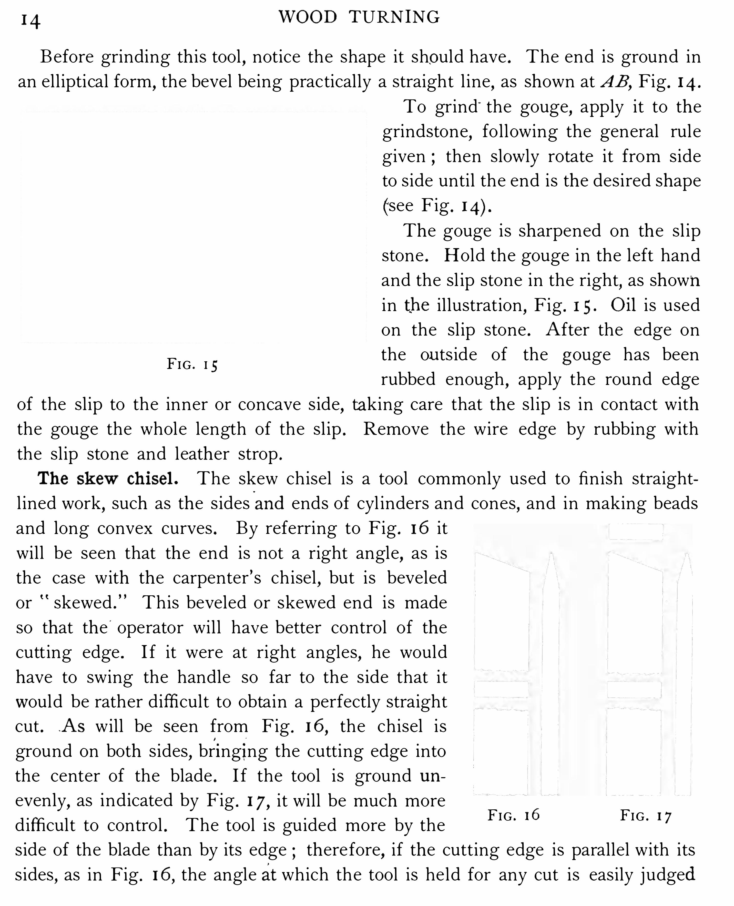
The gouge is sharpened on the sl ip
stone . H old the gouge in the left hand
and the sl ip stone in the right,as shown
in th e il lustration , Fig . I 5 . O i l i s used
on the sl ip stone . A fter the edge on
the ou ts ide of the g ouge has been
rubbed enough,apply the round edge
of the sl ip to the inner or concave s ide,taking care that the sl ip is in contact with
the gouge the whole length of the sl ip . Remove the wire edge by rubbing with
the sl ip stone and leather strop .
Th e skew ch i sel . The skew chisel is a tool commonly used to fin ish straight
l ined work,such as the s idesand ends of cyl inders and cones , and in making beads
and long convex curves . By referring to Fig . 16 it
wil l be seen that the end is not a right angle,as is
the case with the carpenter’s ch isel,but is beveled
or skewed . This beveled or skewed end is made
so that the'
operator wil l have better control of the
cutt ing edge . I f it were at right angles,he would
have to swing the handle so far to the s ide that i t
w ould be rather diffi cult to obtain a perfectly straight
cut . .A s will be seen from Fig . 16,the chisel i s
ground on both s ides,bri ngi ng the cutting edge into
the center of the blade . I f the tool is ground un
evenly,as indicated by Fig . I 7 , i t will be much more
difficult to control . The tool is guided more by the
side of the blade than by its edge therefore,i f the cutting edge is parallel with its
s ides , as in Fig . 16,the angle at which the tool is held for any cut is easily j udged
FIG . I 5
FIG . I 6 FIG . 1 7

GRINDING AN D S H ARPENING TURNING TOOLS 1 5
by the s ide of the blade,whereas if the edge is unevenly ground
,the angle at
which it must be held can only be determined by experimentation .
Fig . 1 8 shows the position of the chisel on the grindstone . A pply the tool to
the stone by the general rule given for grinding (page I and move it from side
FIG . I S FIG . I 9 FIG . 20
to side of the stone,as indicated by the arrow points . The angle
,or skew
,at which
to grind the end should be about 7 5°
(see Fig . The skew is sharpened o n the
oilstone . The bevel should be held flat on the stone,first on one s ide and then on
the other,until the wire edge is removed . By continued sharpen
ing the chise l becomes rounded,as shown by Fig . 19 ,
and must be
ground again . Time is saved by grinding and sharpen ing prom ptly .
Tools will cut faster and smoother when the cutting edges are keen
and sharp ” th an when blunt and dull .
Th e r ound-no se scr ap ing to o l . This tool , shown in Fig . 20,is used
(as its name im pl ies) to cut by scraping rather than by paring . I t i s
used o n fi l lets and concave surfaces . The method of scraping is
given on page 26 . S harpen the tool on the large oilstone,revolving
it in the same manner as a gouge ; turn , and keep the flat s ide of
the tool in contact with the stone . G rind it as you would the gouge .
Th e squar e-no se scr ap ing to o l . Th is tool (see Fig . 2 1 ) i s used in
the same manner as the round- nose scraping tool,and is appl ied on straight and
convex surfaces . S harpen it on the large oilstone,j ust as you would sharpen an
ordinary bench ch isel .
FIG . 2 1
I 6 WOOD TURNING
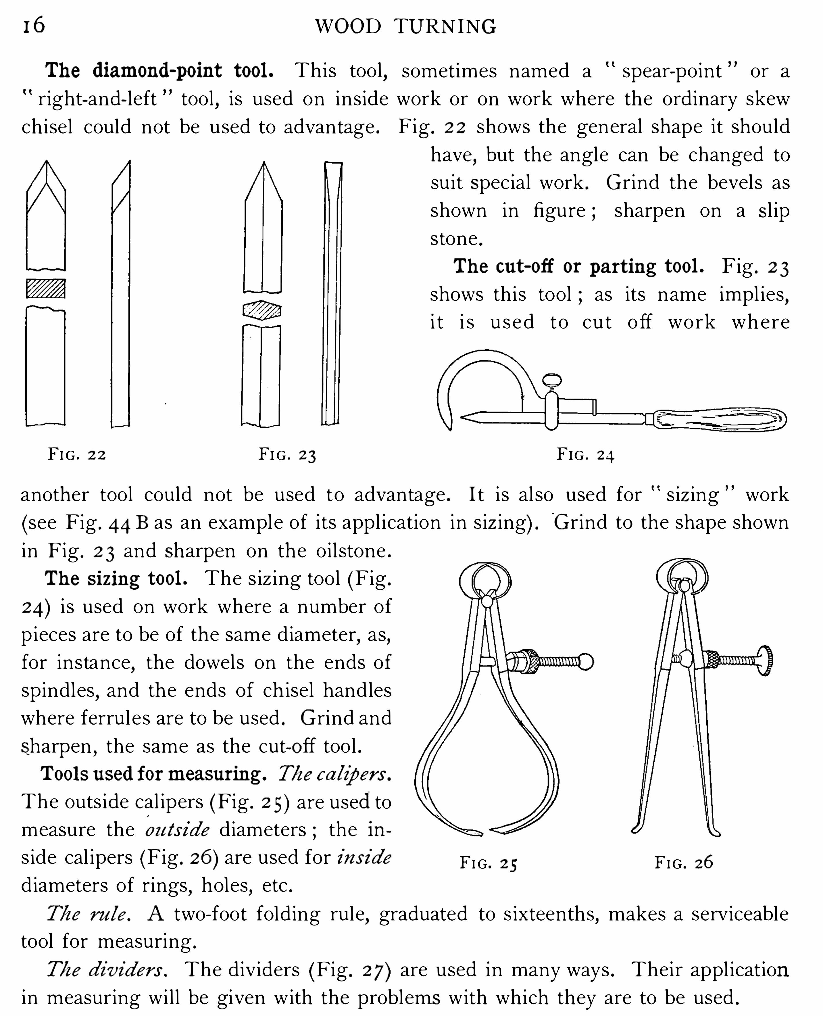
Th e diam ond-p o int too l . Th is tool,
right-and- left tool,is used on inside
ch isel could not be used to advantage .
FI G . 2 2 FI G . 2 3 FIG . 24
another tool could not be used to advantage . I t i s al so used for siz ing work
(see Fig . 44 B as an example of its appl ication in s iz ing) . G rind to the shape shown
in Fig . 2 3 and Sharpen on the oil stone .
Th e si z ing to o l . The s iz ing tool (Fig .
24) i s used on work where a number of
p ieces are to be of the same diameter,as
,
for instance,the dowels on the ends of
spindles,and the ends of ch isel handles
where ferrul es are to be used . G rind and
sharpen , the same as the cuto ff tool .To o ls used fo r m easur ing . Tb e ca lip er s .
The outs ide cal ipers (Fig . 2 5 ) are used to
measure the ou ts i de diameters ; the ins ide cal ipers (Fig . 2 6 ) are used for ins i de FI G . 2 5 FIG . 26
diameters of rings,holes
,etc .
Tb e r u le. A two- foot folding rule,graduated to s ixteenths
,makes a serv iceable
tool for measuring .
Tb e d ivider s . The div iders (Fig . 2 7 ) are used in many ways . Their appl ication
in measuring will be given with the problems with wh ich they are to be used .
sometimes named a spear-point or a
work or on work where the ordinary skew
Fig . 2 2 shows the general shape it should
have,but the angle can be changed to
su it Special work . G rind the bevels as
shown in figure ; sharpen on a S l ip
stone .
Th e cut- off o r p ar t ing too l . Fig . 2 3
shows this tool ; as its name im pl ies ,i t i s u s e d to cu t o ff work wh e re
TO TURN A CYL INDER 1 7
To o ls used fo r sh arp ening . T/ze slip sto ne. The sl ip stone (Fig . 2 8 ) i s used to
sharpen gouges and tools that are curved in their section .
T/ze o i ls to ne. O i lstones are e ither natural or artific ial.The
so -called I ndia oilstone is preferabl e for ord inary sharpen ing.
Use oil on any stone when sharpen ing a tool .T/ze s tr ep . The strop is a p iece of leather cut into such shape
as to conform on its edge to the curve of a gouge . The s ide of
the strop is used for tools that are flat or straight on the edge
S i zes of ch i sel s and g oug es .
The siz e of a gouge or ch isel
i s determined by its Width .
Turning chisels and go uges
come in siz es ranging by eighths,from one eighth of an inch
up to two and one-hal f inches .
Lath e- too l p ract ice.
1 The art of wood turn ing cannot be
learned from a book,but book instruction
,supplemented by
practice under the gu idance of an instructor,will quickly enable the careful student
to do good work . The exercises that fol low are intended to teach the art of wood
turning through various operations on th e speed lathe .
FIG . 2 8
FIG . 2 7
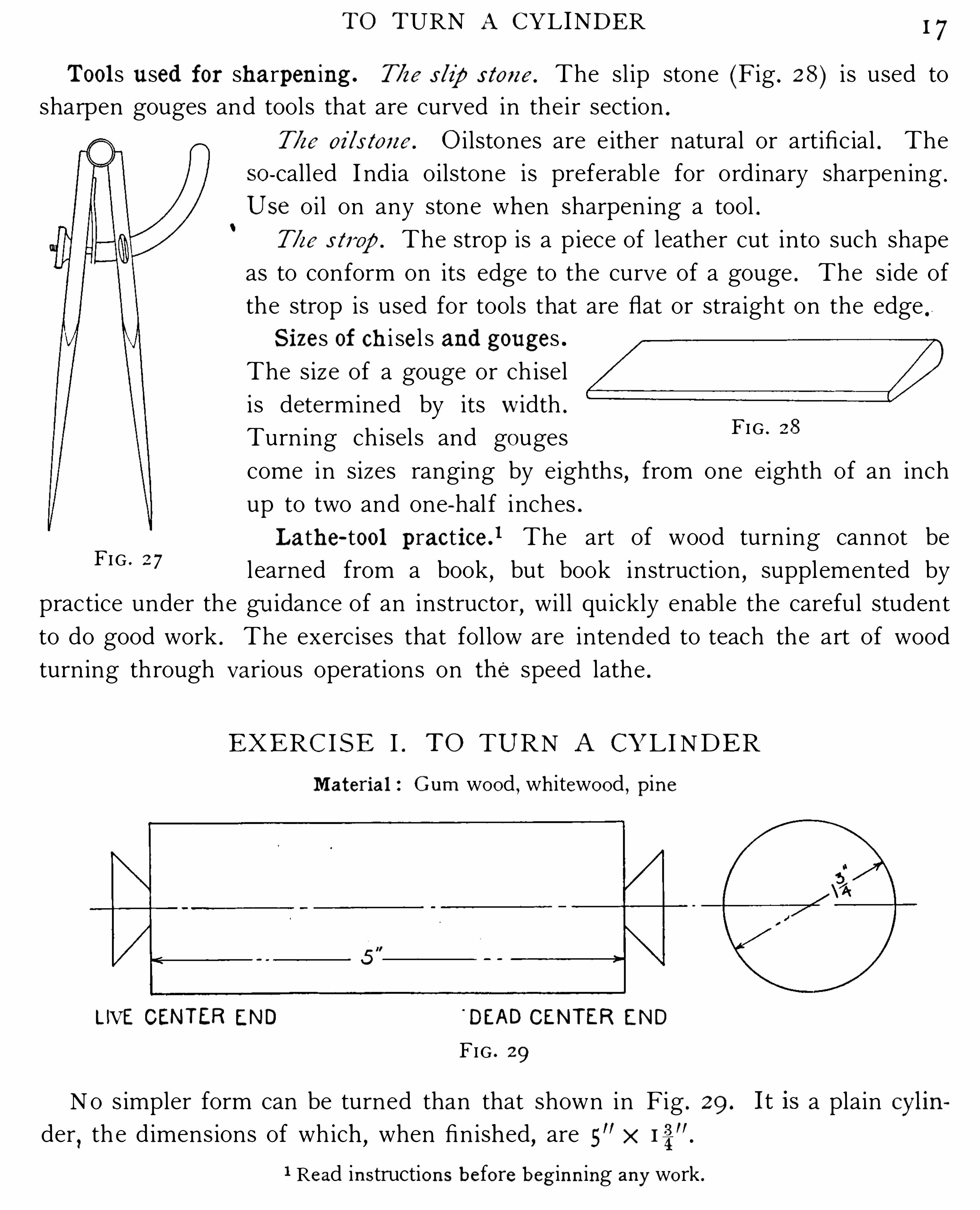
EXERC I S E I . T O TURN A CY L I NDER
Materia l : G um wo o d,wh i tewo o d , p ine
LIVE CEN TER EN D'
DEAD CEN TER EN D
FIG . 29
No s impler form can be turned than that shown in Fig . 29 . a plain cy lin
der,th e d imensions of which
,when finished
,are 5
” x
1 Read instructio ns b efo re b eg inning any wo rk .

18 WOOD TURNING
Turning makes use of two m ethods of cutting ; namely, paring and scr aping .
The student should give close attention to each method as it is appl ied in the vari
ous exerc ises,so that he may come to know wh ich method is the better one to use
on a given piece of work .
T0 tu r n tne cy linder . The rough
stock wil l be 2”x x and square
on the ends by drawing the d iagonals
as in Fig . 30,the center of the p iece
wil l be found at the intersection of the
l ines . Take a center punch or some
suitable tool,and mark the centers ;
then mount the work on the lathe .
To m o unt tb e w o r k . Place the point of the l ive center in the punch mark at one
end ; then push the ta i l stock up toward the work unti l the point of the dead cen
ter is in the punch mark at the other end . C lamp the ta i l stock to the bed . Force
the centers into the work by turn i ng the hand wheel on the ta il stock then loosen
up the dead center until the cone pul ley and the piece of stock revolve freely .
Then set the tool rest and clamp it into position . Put a l ittle oil on the dead cen
ter,and everyth ing wil l be ready for the cutting . For the paring cut
,the tool
rest should be set as
shown at A,Fig . 3 1 , and
for the scraping cut,as
at B,Fig . 3 1 .
The necessary steps to
take in working out th is
FIG . 30
exerc ise are shown in
Fig . 3 2 .
The fi rst operation in
turn ing is called rough i ng down . This is done by us ing the gouge .
To use tbe g o ug e, n otice the method of hold ing it, as shown in Fig . 3 3 . The
left hand,back up
,i s placed on top of the gouge
,which is held by the th ird and
l ittl e fingers ; the right hand is at the end of the handle ; the elbows are kept as
close to the operator’s s ides as poss ibl e . The tool is now laid on the rest, the fleshy
part of the hand touch ing the rest . The body is as nearly square on to the lathe
FIG . 3 1

20 WOOD TURNING
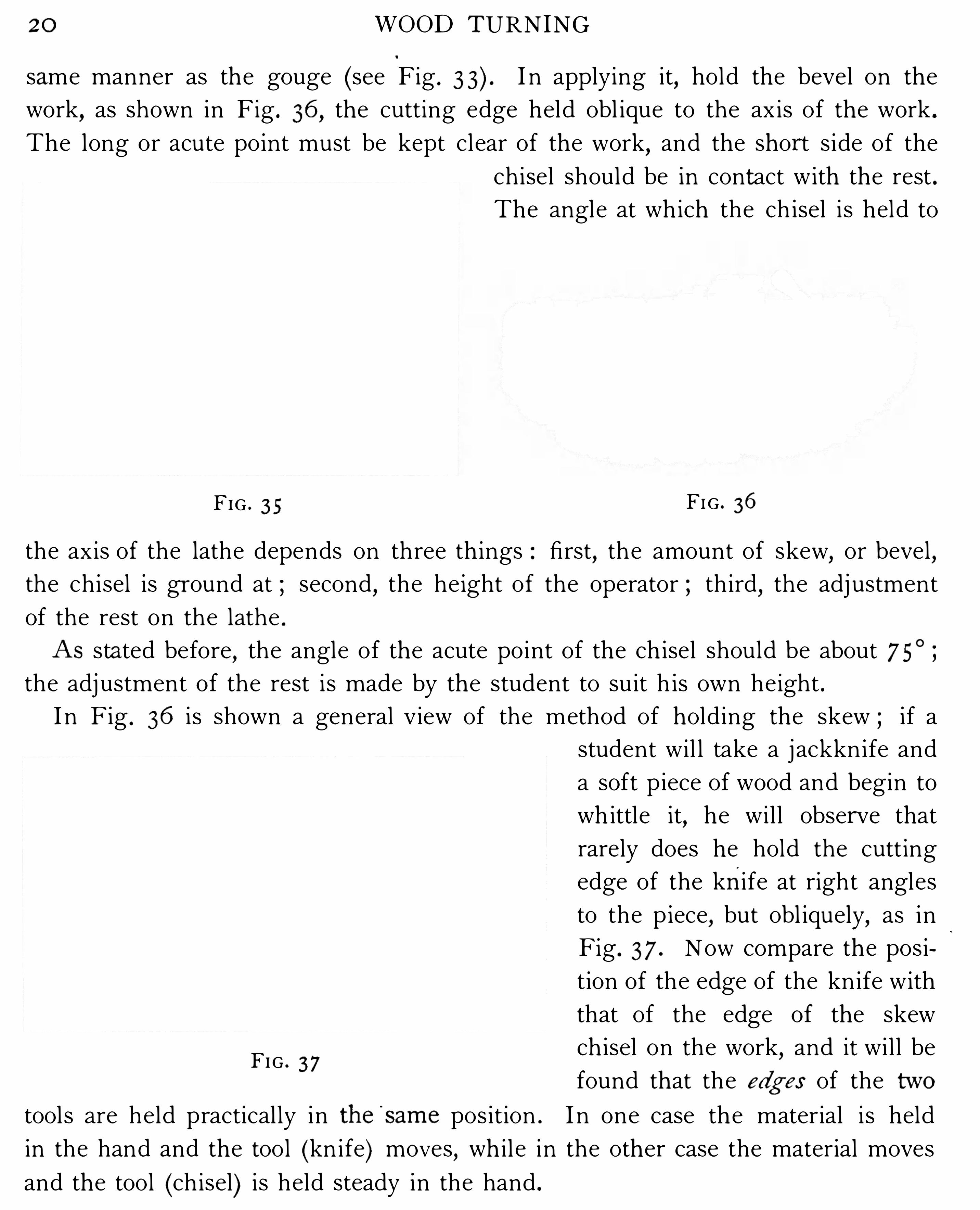
same manner as the gouge (see Fig . I n applying it,hold the bevel on the
work,as shown in Fig . 36 , the cutting edge held obl ique to the ax is of the work .
The long or acute point must be kept clear of the work,and the shor t s ide of the
chisel should be in contact with the rest .
The angle at wh ich the ch isel i s held to
FIG . 3 5 FIG . 36
the axis of the lathe depends on three th ings : first,the amount of skew, or bevel ,
the chisel is gr ound at ; second , the height of the operator ; th ird , the adj ustment
of the rest on the lathe .
A s stated before,the angle of the acute point of the ch isel should be about 7 5
0
the adj ustment of the rest is made by the student to su it h is own height .
I n Fig . 36 is shown a general v iew of the method of holding the skew ; if a
FIG . 3 7
student wil l take a j ackknife and
a soft p iece of wood and begin to
wh ittle it,he wil l obser ve that
rarely does he hold the cutting
edge of the knife at right angles
to the p iece,but obl iquely
,as in
Fig . 3 7 . Now compare the posi
tion of the edge of the knife with
that of the edge of the skew
ch isel on the work,and it wil l be
found that the edg es of the tw o
tools are held practical ly in th e'
sam e position . I n one case the material i s held
in the hand and the tool (kn ife) moves , wh il e in the other case the material moves
and the tool (chisel) is held steady in the hand .
TO TURN A CYL INDER 2 1
Fo r p a r ing we repeat that the rest should be raised above the center, as Shown
In A'
,Fig . 3 1 and for scraping
,it should be set as shown in B
,Fig . 3 1 . Keep the
eyes on the work rather than on the cut
ting edge o f the tool,m ake the sweeping
cut as explained on page 19 in connec
tion with the gouge,and hold the cal ipers
as shown in Fig . 3 5 when trying for di
m ensio ns . Work from the center of the
piece toward the ends,rather than from
the ends toward the center . S ee that the
dimens i ons are correct for diameter .
To cu t t/ze ends,use the long point of
the Chisel . The cutting might be termed sl ic ing,for in paring the end wood a
l ight cut is made so that the work will be smooth,and that the point of the tool
wil l not be burned,or have the tem per drawn by the excessive friction caused
by a deep or heavy cut . Fin ish the dead-center endfi r st ; then measure the length
from th is,us i ng a penci l and rule or a pair of compasses . Fig . 38 i l lustrates the
m ethod of holding the ch isel for the cut
at the right- hand or dead- center end .
FIG . 38
FIG . 39 FI G . 40
The piece should be cut far enough i n from the end ' so that the center marks
shall not be on the finished work . Fig . 39 indicates the m otion the ch isel should
have in making the end cut . A t the left hand (the l ive- center end) the cutting
should be done as indicated in Fig . 40 .
A fter the ends are finished and the cyl inder is cut to the correct length , remove
from the lathe and saw off the surplus material at the bench .
1
1 N o sandp ap er i s to b e used, unless sp ecified fo r given exercises .
2 2 WOOD TURNING
EXERC I S E I I . T O TURN A STE P PED CY L I NDE R
Materi al : G um wo o d,wh i tewo o d
, p ine
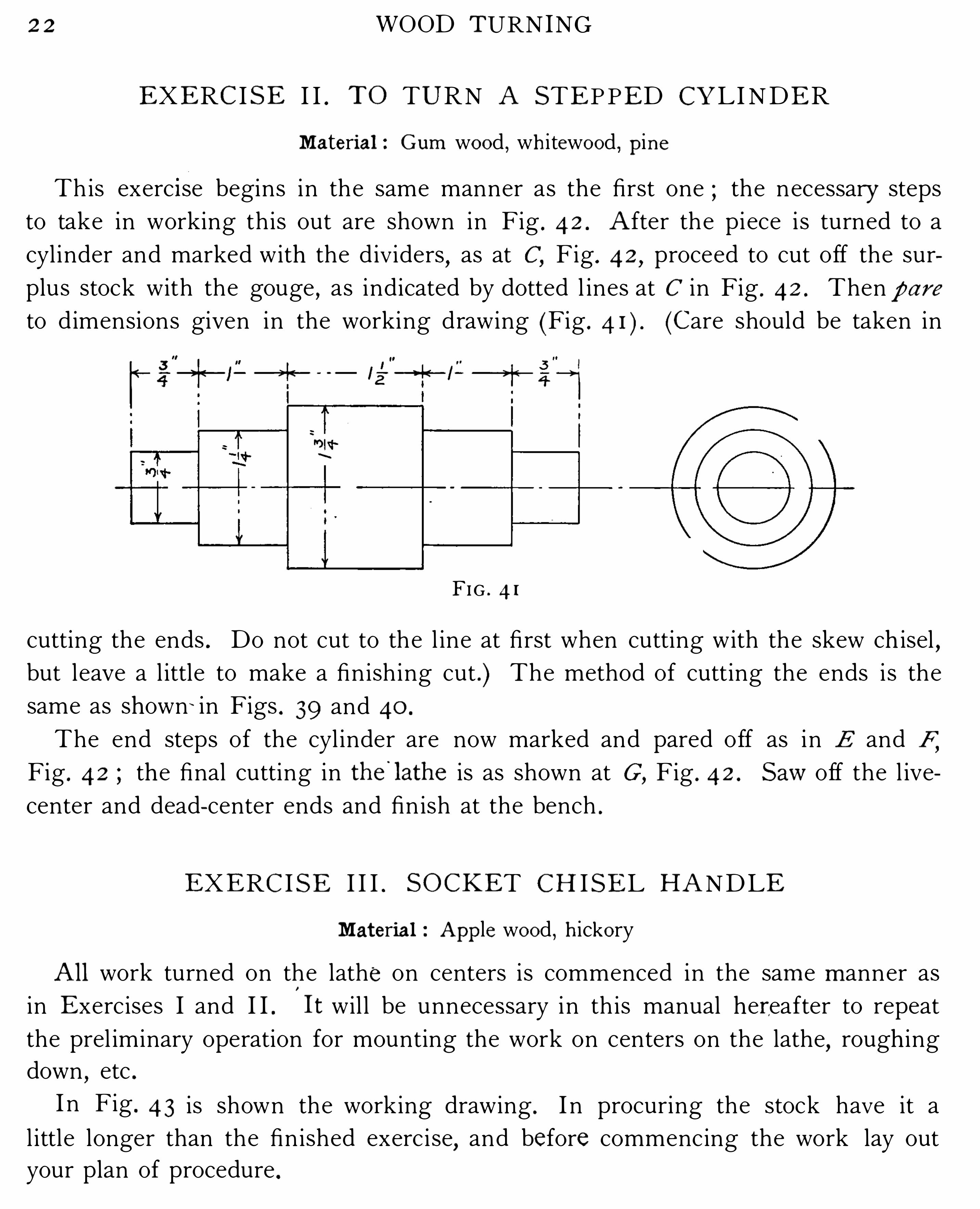
This exerc i se begins in the same manner as the first one ; the necessary steps
to take in working this out are shown in Fig . 4 2 . A fter the piece i s turned to a
cyl inder and marked with the d ividers,as at C
,Fig . 4 2 , proceed to cut off the sur
plus stock with the gouge,as indicated by dotted l ines at C in Fig . 42 . Then p a r e
to d imensions given in the working drawing (Fig . (Care should be taken in
FIG . 4 1
cutting the ends . Do not cut to the l ine at first when cutting with the skew ch isel ,but leave a l ittle to make a finish ing cut . ) The method of cutting the ends i s the
same as shown : in Figs . 39 and 40 .
The end steps of the cyl inder are now marked and pared off as in E and F,Fig . 42 the final cutting in th e
'
lath e is as shown at G ,Fig . 4 2 . S aw off the l ive
center and dead- center ends and fin ish at the bench .
EXERC I S E I I I . S O CKET C H I S E L H A NDLE
Material Ap p le wo o d , h icko ry
All work turned on the lathe on centers is commenced in the sam e m anner as
in E xercises I and I I .
'
I t wil l be unnecessary in th is manual her eafter to repeat
the prel iminary operation for mounting the work on centers on the lathe,rough ing
down,etc .
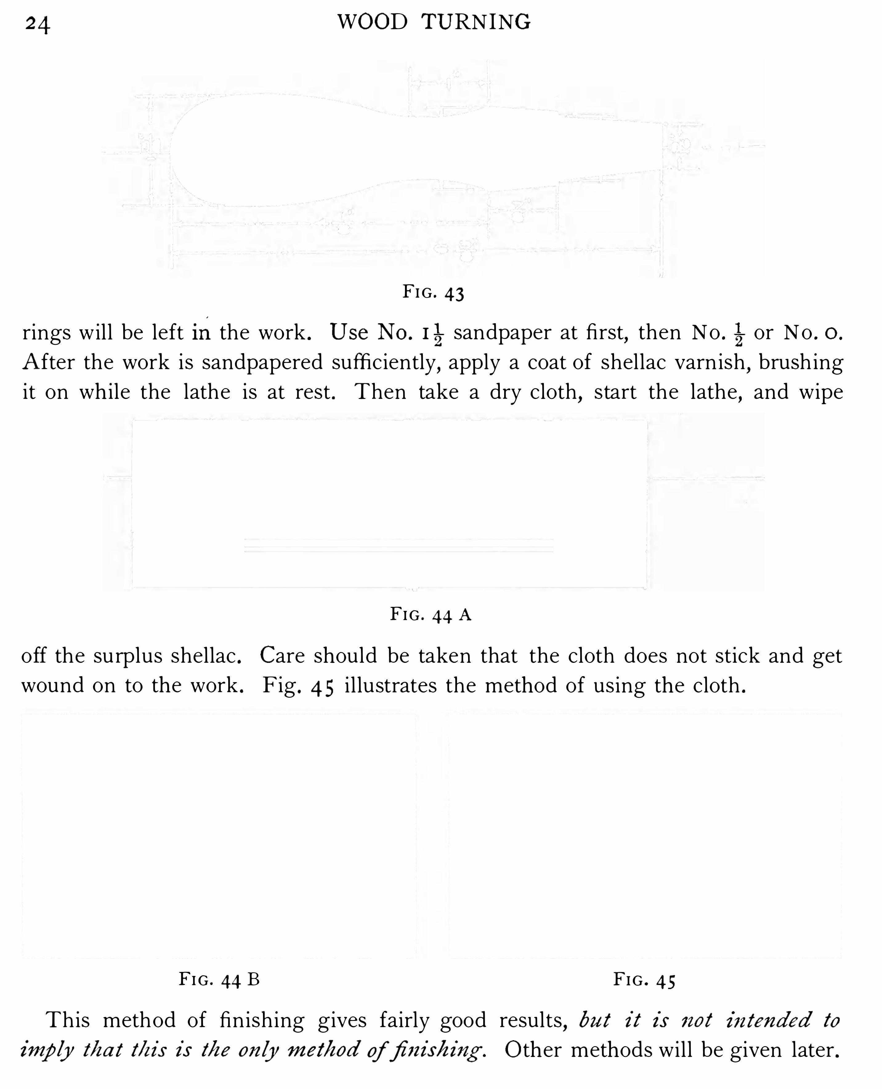
I n Fig . 4 3 is shown the working drawing . I n procuring the stock have it a
l ittle longer than the finished exerc i se,and before commencing the work lay out
your plan of procedure .

SOCKET C H I SEL H ANDLE 2 3
A s the ch isel handle is
intended for a socket chisel,
i t would be advisable to
have a chisel in which to
fit the end,s ince al l ch isel s
are not of the sam e taper .
I f the chisel is not at hand,
and the handle is to be
used later,l eave the l ive
center end on the handle,
so that it can be replaced in
the lathe and fitted into th e
ch i s e l . The d ead - c en te r
end wil l not be cut as in
E xerc ises I and I I,but th is
end of the piece will be the
point to measure from .
T h e operation,after the
piece is turned to a cyl inder,
wi l l be u nde rs tood from
E Fig . 44 A and Fig . 44 B .
This is known as ” siz ing .
”
Take the cut—off tool and
s iz e the severa l diameters,
as shown in the il lustration ;then finish the outl ine of
the handle with the gouge
and ch isel . Finish the work
with sandpaper . I n using
sandpaper care should be
taken not to cut away sharpFI G ' 42 corners . H old the sand
paper (after folding it in a narrow strip ) on the work by the indexand m iddle fingers
and keep it mov ing back and forth the quicker the motion the better,as then no
24 WOOD TURNING
FI G . 43
rings wil l be left inthe work . Use N o . 115sandpaper at first
,then No . or No . 0 .
A fter the work is sandpapered sufficiently,apply a coat of shellac varn ish
,brush ing
it on wh ile the lathe is at rest . Then take a dry cloth,start the lathe
,and wipe
FIG . 44 A
off the surplus shellac . Care should be taken that the cloth does not stick and get
wound on to the work . Fig . 4 5 i l lustrates the method of using the cloth .
FI G . 44 B FIG . 45
This method of finish ing gives fairly good results,bu t i t i s no t i ntended to
i mp ly t/i a t t/i i s i s Me o nly m ei b od offi ni sb ing . O ther methods wil l be given later .

SOCKET C H I SEL H ANDLE 2 5
FIG . 4 7
When a num ber of handles are to be turned,tim e will be saved by making a
templet such as is shown in Fig . 46 . The several d iameters are cut on one edge
of a piece of th in sheet iron,and notches are fi led on the other edge to locate
the positions to be cut while s iz ing .

WOOD TURNING
EXERC IS E IV . TEA POT STAND
Material : O ak, m ah o gany, ch erry, ash , o r any h ard wo o d th at wil l finish wel l
I n Fig . 47 i s shown the working drawing for this piece of work . The m ethods
used are appl icable on such work as rosettes and S im ilar pieces .
The previous exercises were turned on the centers,that is
,the piece was sup
ported o n the lathe by the l ive center and dead center . I n the present exercise the
screw- center chuck E,Fig . 7 , is used . The method
of cutting i s termed scraping .
”
T/ze scr ap i ng cu t . This cut is m ade by laying
the ch isel flat on the rest instead of ti lting it up,
as in the paring cut . The ch isel Should be kept
sharp and the scraping or cutting should be done
l ightly in order to obtain a smooth surface . To
fix the rest for th is p iece and to turn the disk,
see the il lustrations,Figs . 48 and 49 . These
illustrations show the piece with the corners cut
off,the rest set across the face
,and the skew chisel in position for cutting off
the corners and squaring up the edge .
The diameter of the disk can be measured off with the compasses . S tart the lathe
set the compasses to the radius and
place one po int on the center of the
piece,bringing the other point down
on the rest and push ing it against
the face of the piece . The l ine will
be marked whil e the piece is r e
volving .
The back corner of th e piece is
l iable to spl it off if the ch isel i s
pushed all the way across,so that
about 3gof an inch
‘
sh ould be left uncut ; then set the rest across the edge
(see Fig . cut off th e material with the gouge,and scrape smooth with the
skew ch isel .
FI G . 48
FI G . 49


2 8 WOOD TURNING
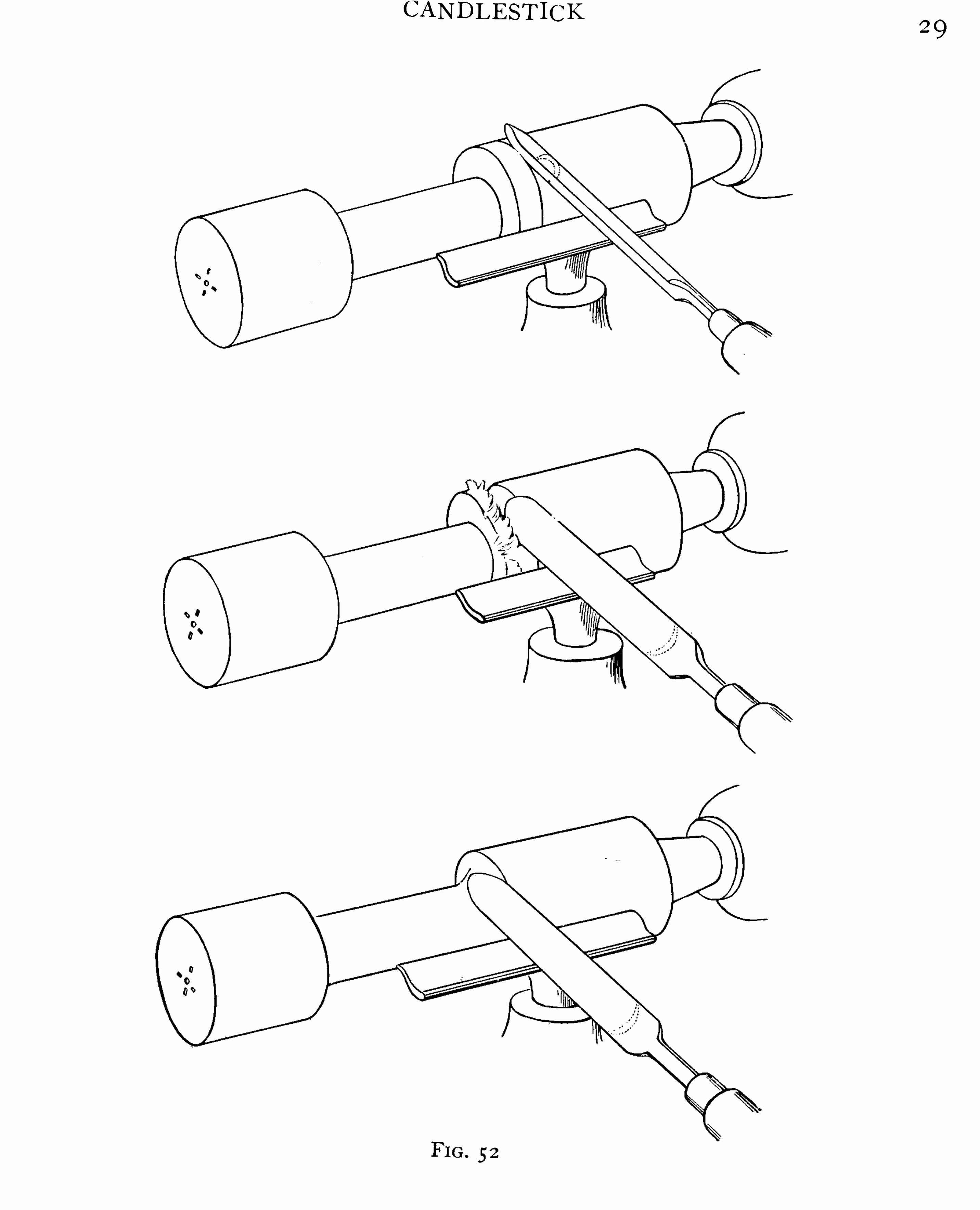
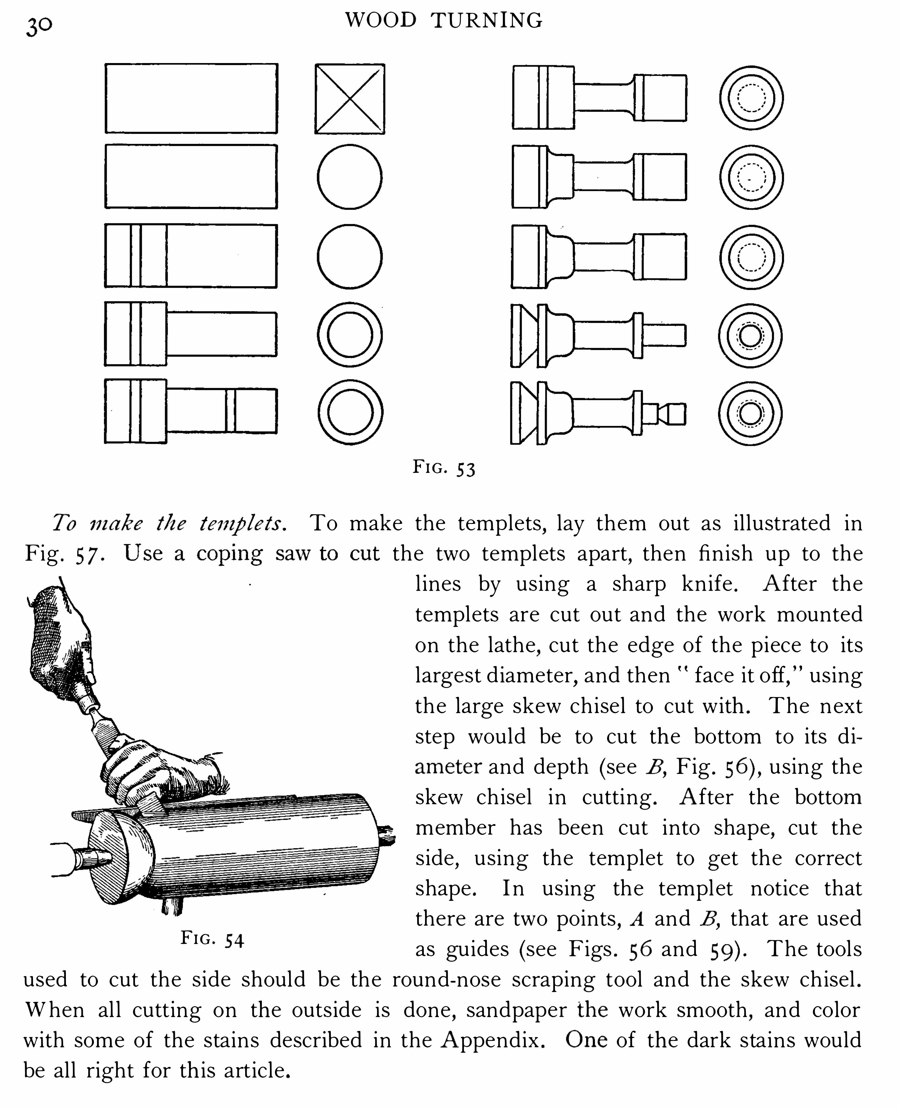
will be understood from the il lustration , Fig . 5 2 . The necessary steps in working out
th is par t of the exerc ise are shown in Fig . 5 3 . To cut the concave curves, use the
small gouge and cut,as shown in Fig . 5 2 , which shows three positions . Make a clean ,
smooth cut . For the convex curve use the small skew chisel . (S ee Fig . 54 ,which
shows the method of cutting . ) I t would be advisable for the student to practice
cutting th e curves on a waste piece of stock before trying the exercise . I n cutting
the curves swing the handle of the chisel or gouge with a ful l movement . Notice
that if the tools sl ip and dig into the work,i t is due to the fact that they are held
in one direction wh i l e the student is trying to make them cut in another . Make
zi — fi f—E
n
—j‘égl
FI G . 5 1
the direction of the tools correspond with the direction of the cut . Tb e b o le i n tb e
end i s tu r ned after th e p i ece b as beenfas tened w i t/cg lue i nto t/ze base.
To turn the base (Fig . 5 5 ) a face plate (see C,Fig . 7 ) is required, and as no
screw holes are to be left in the work when finished,a study of the method of
operati ons 18 necessary .
The stock from which the base i s turned is fastened with screws to the face platethe side nearest the face plate wil l be the top or upper s ide when the piece is fin
i sh ed,so that the bottom side of the piece wil l be turned first . The edge is cut in
the same way as explained in E xercise IV .
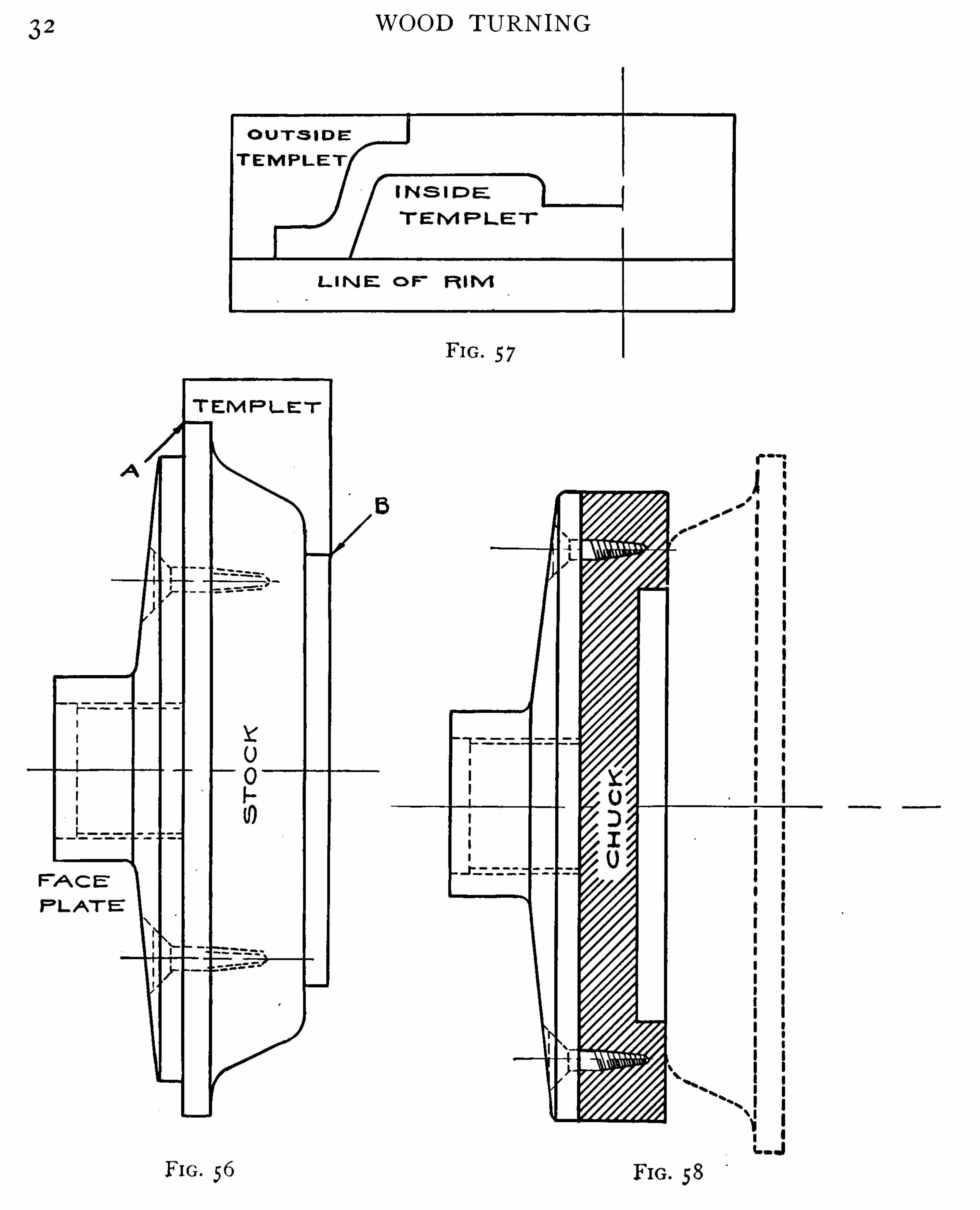
I n order that the wal l mayb e of equal th ickness,templets are used . A temp
let is a form or pattern cut out of th in material,and is used on th e work as shown
in Figs . 56 , 59 .
CANDLEST ICK2 9
30 WOOD TURNING
FIG . 5 3
To m abe Me To make the templets,lay them out as il lustrated in
Fig . 5 7 . the two templets apart,then finish up to the
l ines by using a sharp knife . A fter the
templets are cut out and the work mounted
on the lathe,cut the edge of the piece to its
largest d iameter,and then face it off
,using
the large skew ch isel to cut with . The next
step would be to cut the bottom to its d i
am eter and depth (see E ,Fig . using the
skew ch isel in cutting . A fter the bottom
member has been cut into shape,cut the
side,using the templet to get the correct
shape . I n using the templet notice that
there are two points,A and B
,that are used
as guides (see Figs . 56 and The tool s
used to cut the side should be the round-nose scraping tool and the skew ch isel .
When al l cutting on the outside is done,sandpaper th e work smooth
,and color
with some of the stains described in the A ppendix . O ne of the dark stains would
be all right for th is art icle .
FIG . 54

CANDLE ST ICK 3, 1
T hefinish should be e ither shellac or w ax. To finish with shellac,the work can
be either a rubbed finish,l ike Exercise IV
,or a two-coat finish and rubbed with
pum ice and oil , or water (see Appendix ) . The w ax finish is appl ied with a rag and
is left to dry fo r a short tim e,and is then pol ished with a dry
,soft cloth
,while the
lathe motion .
When the surface is fin ished the work is taken off the face plate and chucked
that is,the work h as to be turned around so that the s ide which was against the
face plate would be out . To do th is,a piece of wood is fastened on the face plate
and a recess is turned into it,as shown in Fig . 58 . The piece of work is held in
the chuck by friction,a good tight fi t being al l that is needed to hold it . This
operation is term ed chucking . When the piece is chucked and the work revolves
true,commence to cut i t out
,using the round- nose scraping tool ; then finish with
the square-nose scraping tool or th e skew ch isel .
3 2
P LA T
FI G . 56
WOOD TURNING
FI G . 58

CANDLEST ICK 3 3
The templet appl ied to the work is shown in Fig . 59 . A fter the piece has been
cut into shape,turn the hole in the hub as Shown in the working drawing
,fit and
glue the upright in place,being careful that it i s fastened true ; when the glue is
dry ,turn the hole (which holds the candle) ; sandpaper the work smooth , and
finish the same other side .
FIG . 59
The principles underlying work of th is character are very important to the student
who intends to take up pattern making ; the principles and methods are appl ied
extensively in the turn ing of patterns . A s a supplementary l esson the student should
be encouraged to design pieces of work in which the same principl es are appl ied asthat given in connection with the candlestick ; that is , a piece that would require
templets and also chucking to work it out .
34 w o o D TURNING
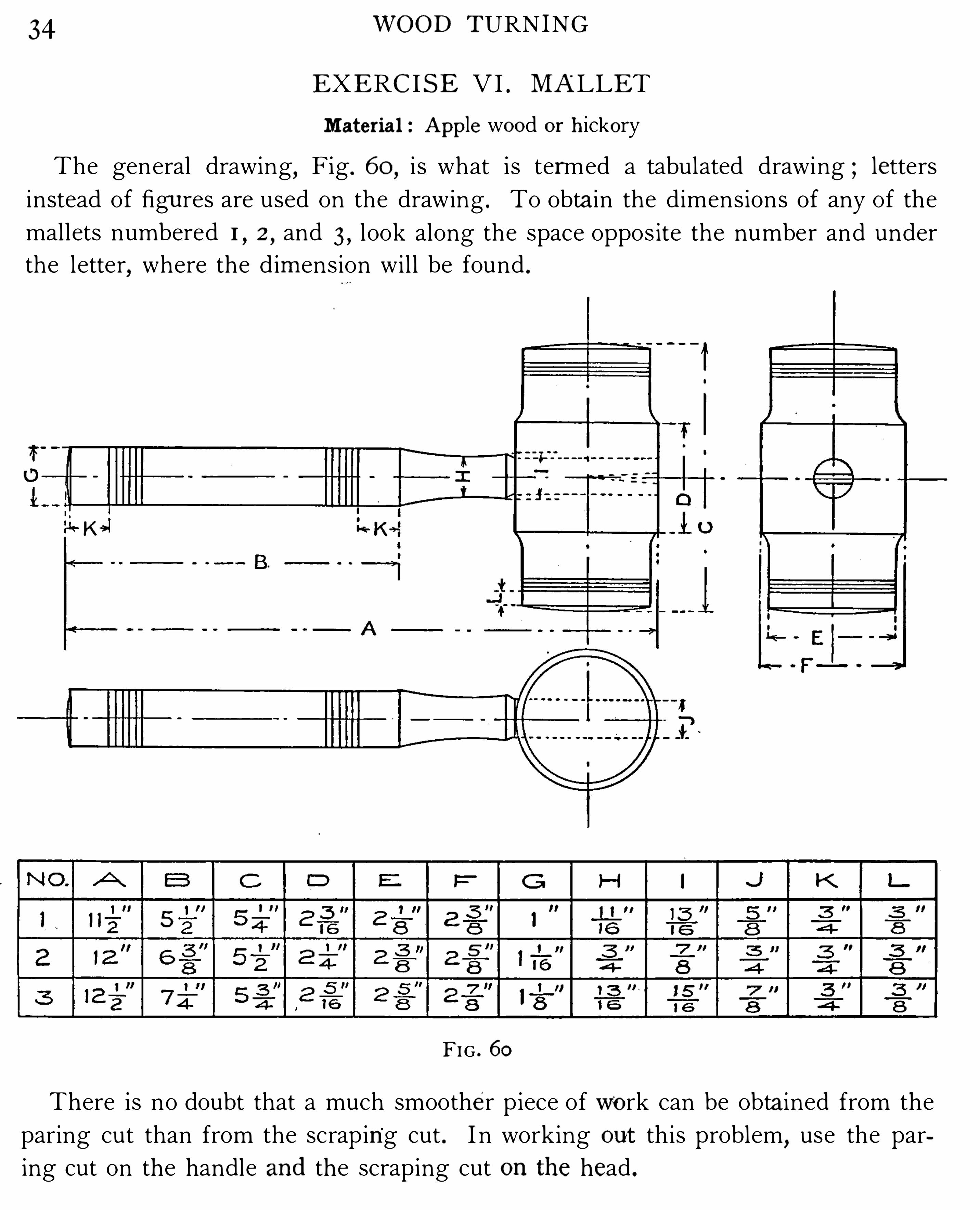
EXERC I S E VI . MA LLET
Mater ia l : Ap p le wo o d o r h icko ry
The general drawing,Fig . 60
,i s what is termed a tabulated drawing ; letters
instead of figu res are used on the drawing . To obta in the dimensions of any of the
mallets numbered 1,2,and 3 , look along the space oppos ite the number and under
the letter,where the dim ension wil l be found .
FIG . 60
There is no doubt that a much smoother p iece of wo rk can be obta ined from the
paring cut than from the scraping cut . I n working o ut th is problem,use the par
ing cut on the handle and the scraping cut on th e head .

WOOD TURNING
To loca te t/i e p o ints to bo r efo r tb e b andle. To lay out the hole,take a compass
and set it to the radius of the larger circle,that i s
,largest diameter . Commence at
a point sel ected on the center l ine and space off three spaces on one side,then go
back to the sta rting point and space off three spaces on the other side . Most l ikely
it wil l be found that in spacing,the points wil l not meet (see A ,
Fig . Div ide
th i s space equal ly thi s wi ll give the point on which to bore the first point will be
the point to bore on the other s ide .
I n boring,i t m ight be well to have some o ne to l ine up the bit
,that is
,to see
that the bit is held at right angles to the ax is of the cyl inder . When the hole is
bored,drive the handle into the head and fasten it in with a wedge
,hav ing the
wedge in the pos ition shown in the drawing .
The next step is to trim and smooth al l ends and finish with shel lac . Two coats
of shel lac wil l be suffi cient .
EXERC I S E VI I . CA NDLE STICK
Mater i al : Mah o gany,birch
,ch erry, o ak , o r m ap le
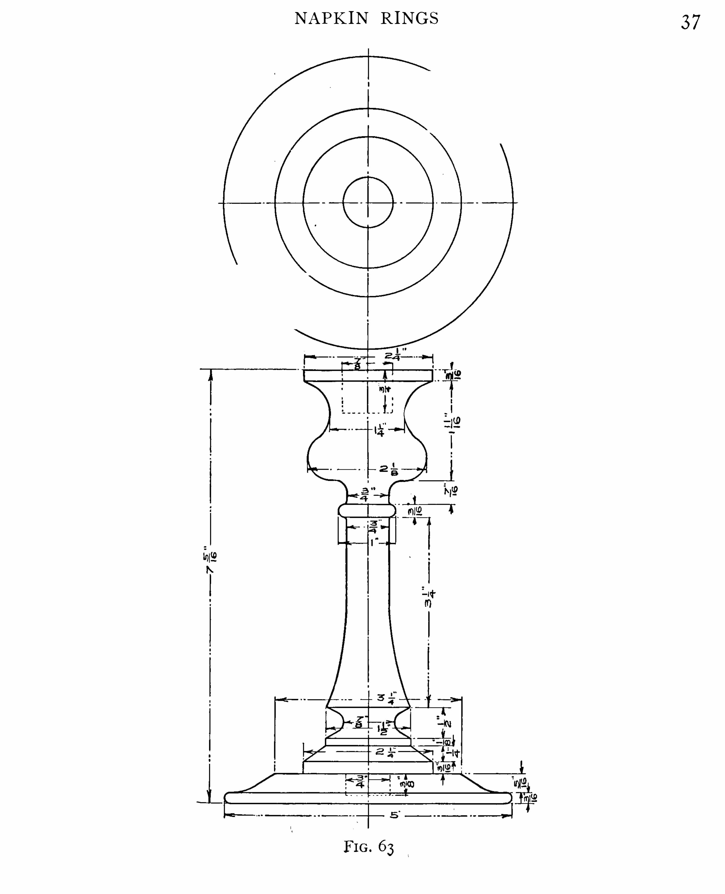
This piece of work (Fig . 6 3 ) i s made of two parts ; the upright being turned
between centers and the base on the screw chuck .
I n turn ing the beads on the upright,care should be taken while using the ch isel
,
so that it will not sl ip . Rol l the ch isel to follow the curves with a ful l swing . I n
cutting beads,it might be wel l for the pupil to practice on a waste piece some of
the m i scellaneous exercises given at the end of th is manual could be selected
for practice .
The base is cut plankwise'
of the stock in the same manner that the base in
E xerc ise V is cut . The hole in the top is turned after the upright is fastened
into the base .
An ebony,or any of the dark stains
,i s pecul iarly appropriate for th is p iece
of work .
EXERC I S E VI I I . NA PK I N R I N G S
(B E LL C H UCK W ORK)Materi al : B irch
,m ap le, ap p le, o r any clo se-grained h ard wo o d
The methods of turning,given in connection with th is exercise
,ap pl icable
hollow work,such as cups
,vases
,etc .
NAPK IN RINGS 3 7
38 WOOD TURNING
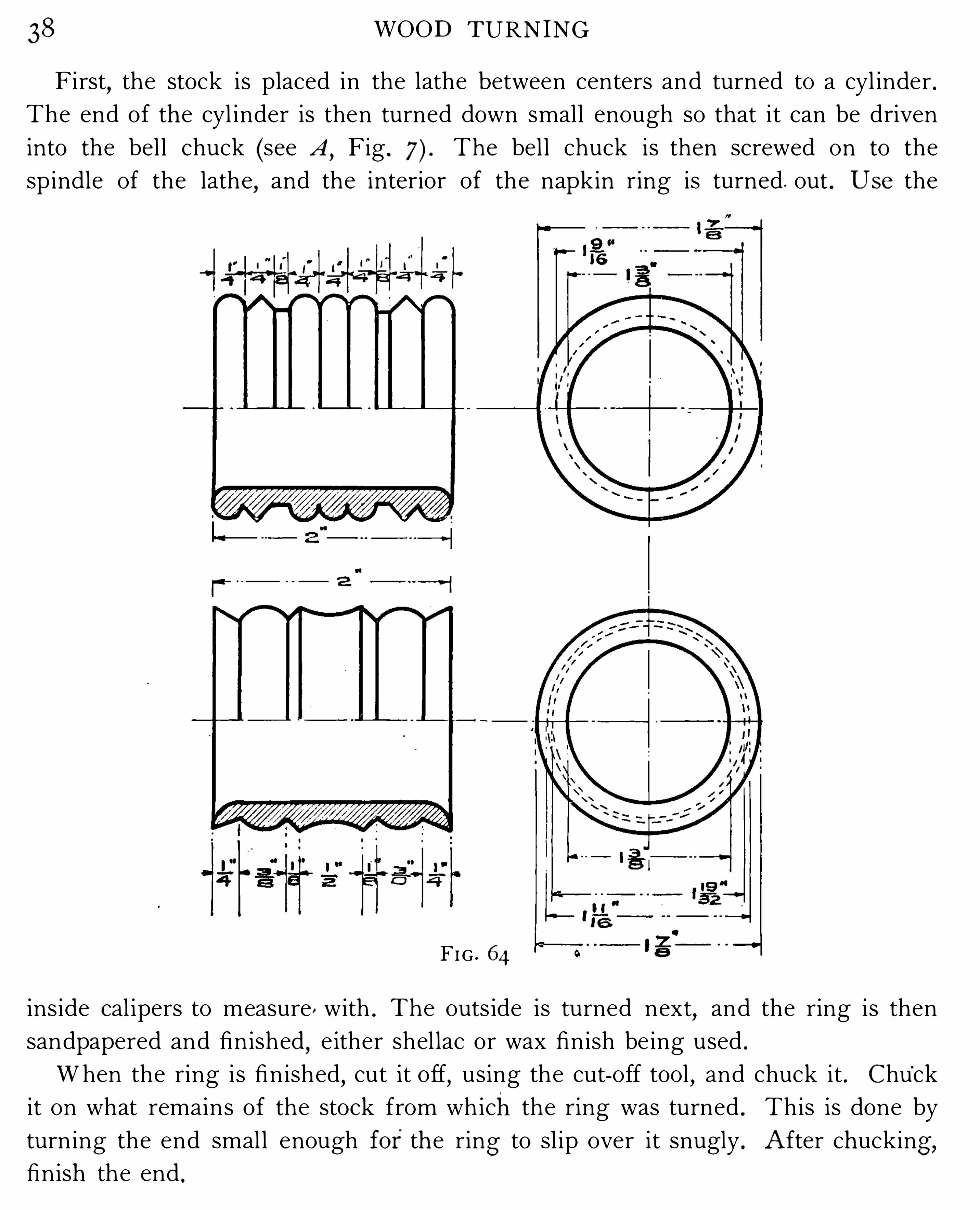
First,the stock is placed in the lathe between centers and turned to a cyl inder .
The end of the cyl inder is then turned down small enough so that it can be driven
into the bel l chuck (see A ,Fig . The bel l chuck is then screwed on to the
spindle of the lathe,and the interior of the napkin ring is turned . out . U se the
FI G . 64
ins ide cal ipers to measure , with . The outs ide is turned next,and the ring is then
sandpapered and finished,e ither shel lac or wax finish be ing used .
When the ring is finished,cut it off
,using the cut-off tool
,and chuck it . Chu
’
ck
it on what remains of the stock from which the ring was turned . This is done by
turn ing the end smal l enough fo r the ring to sl ip over it snugly . A fter chucking ,finish the end .

SMALL BOX 39
To m ake a subs ti tu tefo r a bell e/i nck . Where no bel l chuck can be had,a subst i
tute for a bell chuck m ay be m ade by using a wood face plate,turn ing out a hole in
the center to receive the sto ck . To m ake it doubly secure,the stock m ay be glued
into the face plate .
S om etim es such w ork is fastened on the screw- center chuck . \Vhen the piece
is long,th is method of hold ing it is not advisable .
EXERC I S E I X . SMA LL B OX
Ma terial : Mah o gany,birch
,ch erry
The student should always keep in m ind that there is usual ly more than one
in which a piece of wo rk can be m ade . The m ethod given with th is piece is
that i s used extens ively in pattern m aking .
FIG . 65
Us ing g lue and p ap er to m o unt t/i e w o r k . I n preparing the stock for the lathe ,proceed as follows : fi rst
,secure an i ron face plate (two if conven ient, one for the
bottom,and one for the cover of the box) , fasten a wood face plate to it, and turn

40 WOOD TURNING
FI G . 66

SMOKERS ’S ET 4 1
i t tru e . Cut the corners off the p ieces from which the box is to be made , glue a piece
of paper on the face plate,then glue the stock to the p aper and clam p with a
hand screw . When the glue is dry the piece is ready to be turned . Methods of
turn ing are the sam e as in E xerc ise V . When the ins ide and outside of the box
is turned,sandpaper
,stain
,and finish . (U se som e of the sta ins and finishes given
in the Appendix . )To r em ove t/ze w o r k fr om t/ze face p la te . T o remove from the plate
,drive a
ch isel between the face plate and the box . The p aper w i l l spl it . Chuck the work
on the plate to fin ish the bottom .
The inside of the cover should be turned fi rst ; th is wil l be the better way , for
the groove and flat surface give a better chance for chucking than the rounding
side would . Fin ish the same as the body , then chuck it and turn the outs ide of
the cover,and finish . The use of p ap er on the face plate does aw ay with all screw
holes in the work .
EXERC I S E X . SMOKERS’
S ET
Material : Ch erry,birch
,o ak
The design given here is only suggestive ; the student m ay submit an original
design to the instructor before undertaking to make this piece .
The m etho ds of turn ing in th is exercise ar e a combination o f the methods pre
vio usly given . To a great extent the pupil should rely on h is own skil l and abil ity
in working out this piece .
S tain ing and finish ing should al l be do ne before the pieces are rem oved from
the chucks,being carefu l not to get the fin i sh ” on the parts that are to be glued
to the base . G lue wil l not stick to varn ish or shel lac .
EXERC I S E XI . TO W EL RA ILS
Ma terial : B irch,o ak
,ash
,ch erry
,o r m ap le
I n the fig ure is shown the assem bly drawing of th is piece of work . The student
should study out the pieces from it,instead of having a detail drawing of each piece .
I n regard to the arms or pieces that support the arm s,the worker wil l notice
that they are pieces which are turned up on centers,and previous instruction wil l
suffi ce for these . The balls on the supporting pieces are turned in the sam e manner
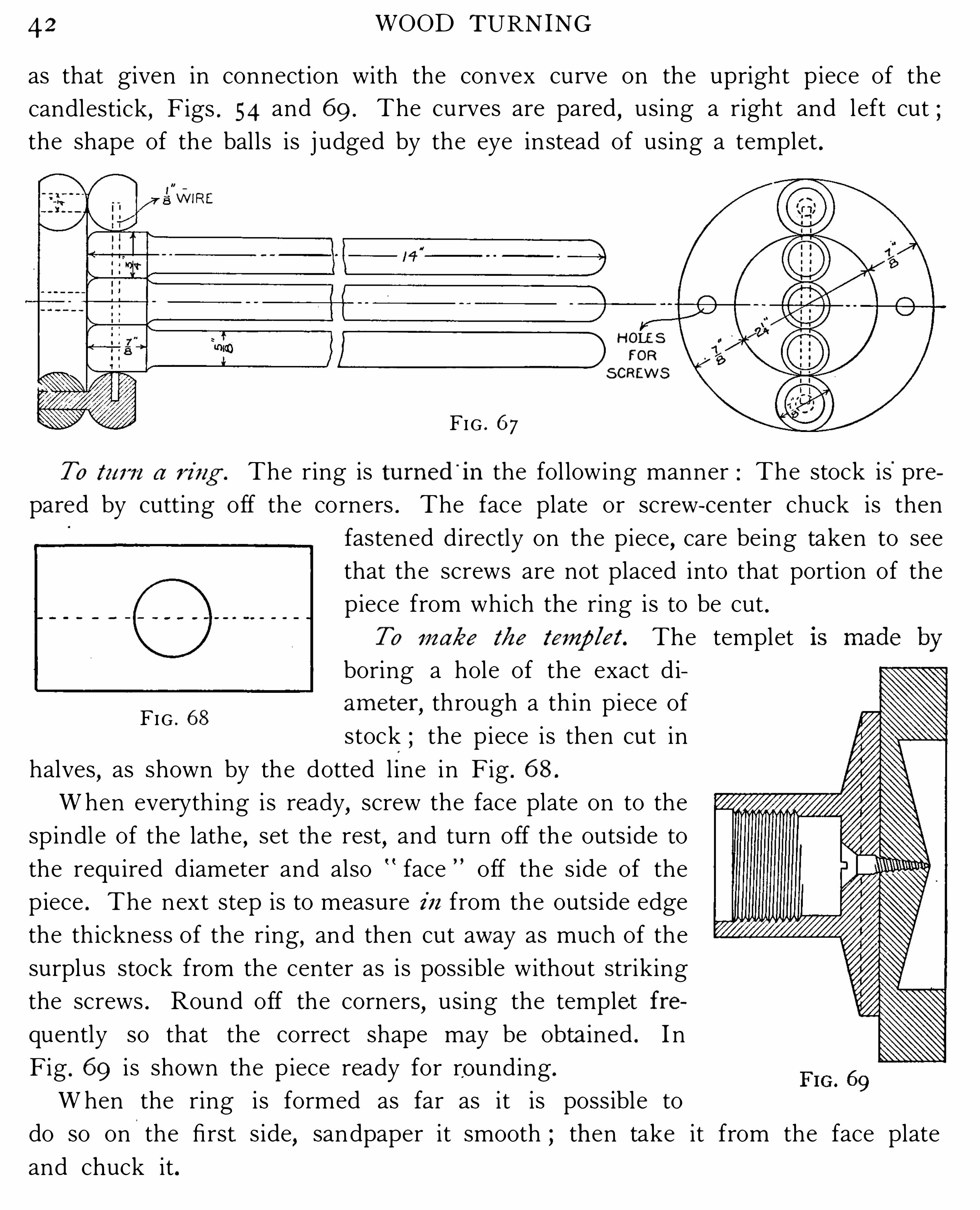
42 WOOD TURNING
as that given in connection with the convex curve on the upright piece of the
candlestick,Figs . 54 and 69 . The curves are pared
,using a right and left cut ;
the shape of the balls is j udged by the eye instead of using a templet .
H OLESFOR
S CREWS
FIG . 67
To tu r n a r i ng . The ring is tu r ned'
in the fol lowing manner : The stock is'
pre
pared by cutting off the corners . The face plate or screw- center chuck is then
fastened directly on the piece,care being taken to see
that the screws are not placed into that portion of the
piece from which the ring is to be cut .
To m ake tbc temp let . The templet
boring a hole of the exact d i
am eter,through a th in piece of
stock ; the piece is then cut in
halves,as shown by the dotted l ine in Fig . 68 .
When everyth ing is ready,screw the face plate on to the
spindle of the lathe,set the rest and turn off the outside to
the requ ired diameter and also face off the side of the
piece . The next step is to measure i n from the outside edge
the th ickness of the ring,and then cut away as much of the
surplus stock from the center as is possible without striking
the screws . Round off the corners,using the templet fr e
quently so that the correct shape may be obta ined . I n
Fig . 69 i s shown the p iece ready for ro unding .
When the ring is formed as far as it is possible to
do so on'
the fi rst. s ide,sandpaper it smooth ; then take it from the face plate
and chuck it.
FIG . 68


44WOOD TURNING
When all the cutting is done,finish with No . I N o . 3, and N o . 0 sandpaper,
after wh i ch remove from the . lath e and finish off the ends of the handles at the
bench .
No oil or varn ish of any kind i s used on th is piece of work . A screw eye may
be put into the end of one of the handles to hang it up by .
EXERC I S E X I I I . POTATO MA S H ER
Materi al : Map le
The methods appl ied on th is exercise are practical ly the sam e as those given in
E xercise X I I .
I n th is piece of work long convex curves and short concave curves are the
special features . A ll the cutting may be done With the gouge, with the exception
FI G . 7 2
of the ends which require the ch isel to finish,or both the gouge and the ch isel may
be used on the side .
Fin ish with No . No . and No . 0 sandpaper . (Neither oi l nor varn ish is
to be used on this p iece . ) When the work is fin ished on the lathe remove and
trim the ends at the bench .
EXERC I S E X IV . CARD RECE IVER
Materi al : Ch erry, o ak , m ah o gany,birch
I n work of th is character it i s advisable to use a templet for both the outside
and inside . A s before stated,when a tem plet is used
,two points are required as
g uides in placing it . I n making the t emplets use th in stock,long enough to

CARD RECE IV ER 45
reach across the work so that a bearing may be had on both‘
s ides of the piece .
Figs . 56 and 59 show templets bearing on the two points . The outer edges of the
card receiver would be the points of contact for the tem plets in this case
I n preparing the stock for the lathe the m aterial should be mounted on a wood
face plate fastened to the regular iron face plate . To do th is the method and
D IA M .
instructions given in connection with the box on page 39 should be followed ; that
is,glue to plate with paper between .
When the piece is finished and sandpapered,i t will be better to chuck it in order
to smooth off the bottom,although th is is not absolutely necessary
,as the bottom
may be finished off with the plane at the bench .
The finish and stain to be u sed wil l depend on th e kind of wood . The dif
fer ent stains and finishes wil l be found in the A ppendix .
6 WOOD TURNING
S U PPLEME NTARY EXE RC I S E S
Many useful and ornamental pieces of work can be turned out on the speed
lathe l ight and dark- colored woods in combination,formed into designs , are often
used to produce effects on turned work that are artistic and the student i s adv ised,
whenever poss ible and time permits,to design and bu ild up pieces of such work
where the contrast between the woods wil l be marked . The r esults wil l more than
compensate for the trouble and work of glueing up the stock .
I n preparing stock for such work the surfaces should be planed to a perfect fit
before being glued together,as a poor j oint would be l ikely to ru in the work wh ile
being operated on in the lathe .
I n the fol lowing supplementa ry exercises there has been no effort made to intro
duce what is usually termed fancy turn ing,such as the turn ing of ell iptical forms
,
turning ball s inside a ball,turn ing loose rings on a spindle
,trefo ils
,and work wh ich
requ ires much man ipulation in chucks . The proj ects selected are ones which the
average student should be able to carry out successfully,in V iew of h is prev ious
experience . S tudents are adv ised,at th is stage
,to submit original designs to the
instructor in charge,that the difficulties connected with the execution of these
pieces may be made subj ects for class discussion .
The exercises,Figs . 74 to 8 7 , are intended to supplement previous work , and are
also suggestive for larger p ieces and practice in develop ing speed in turn ing out
work on the lathe .
The names of the fo llo w m g p i eces are given as suggestions for the student to
des ign . When a large piece is turned,i t i s rarely turned from sol id stock
,but is
built up . I n design ing a piece th i s should be taken into consideration,so that the
j oints may not be too conspicuous,unless the woods were l ight and dark
,when the
j oints should be absolutely symmetrical with the axis of the piece .
N am es of p i eces . Pi ano stool (may be com b i ned with a piece of bench work) ,legs for colon ial table (the top and shelf would be bench work) , serv ing trays,bread boards , table mats, candlesticks , bowls for nuts , rose j ars , vases, spindles for
furn iture, l egs for pieces of furn iture , pedestals , base and pen rack for ink stand ,foot rests , game boards, circular hand m irrors , collar and cuff box, j ewel boxes ,walking sticks
,match safes
,etc .
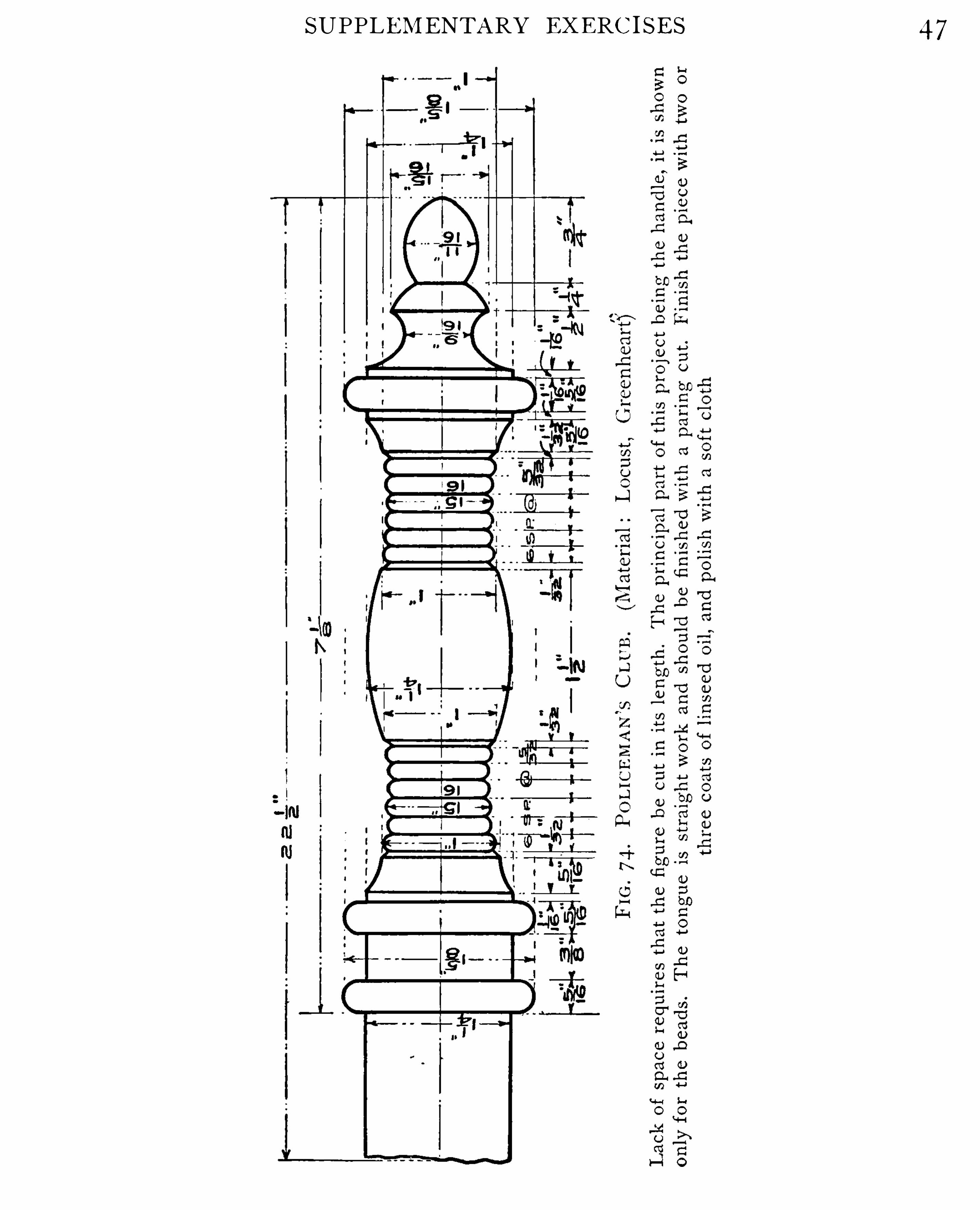
SUPPLEMENTARY EXERC I SE S 47
WOOD TURNING

SUPPLEMENTARY EXERC I SES 49
I”
FI G . 76 . BOWL
(Material : B irch,O ak
,Walnut)
Th is p iece S h o uld b e m o unted o n a face p late w ith g lue and p ap er, and tem p lets sh o uld b e used to
cut b y . Th is article i s V ery useful o n a l ib rary table as a catch - al l, and if fo r any r easo n a co ver i sneeded fo r it, o ne m ay very easi ly b e designed . Finish ed in dark m ah o gany i t p resents a very
p leasing effect
WOOD TURNING
I
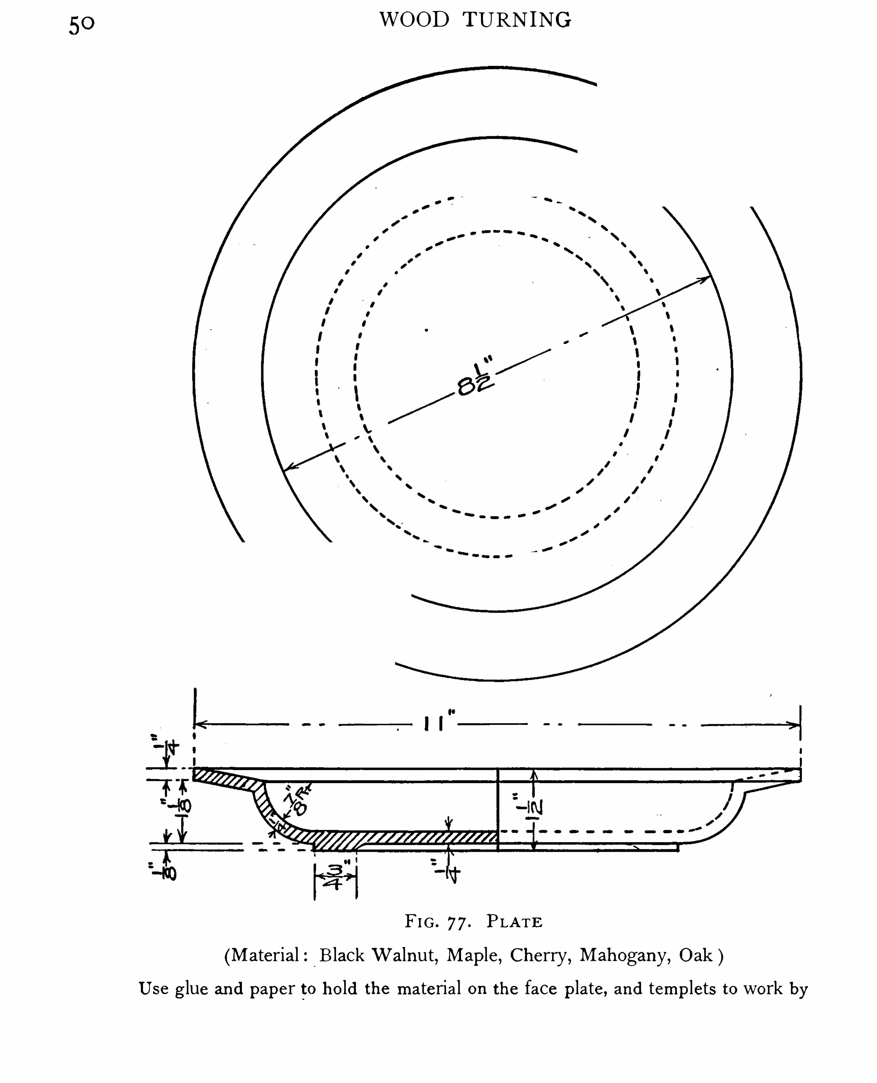
FI G . 7 7 . PLATE
(Material : B lack Walnut,Map le, Ch erry, Mah ogany, O ak )
Use g lue and p ap er to h o ld th e m ateria l o n th e face p late, and tem p lets to wo rk by


5 2 WOOD TURN ING
FI G . 79 . POWDE R B OX . (Material : O ak , Ch erry, Mah o gany)
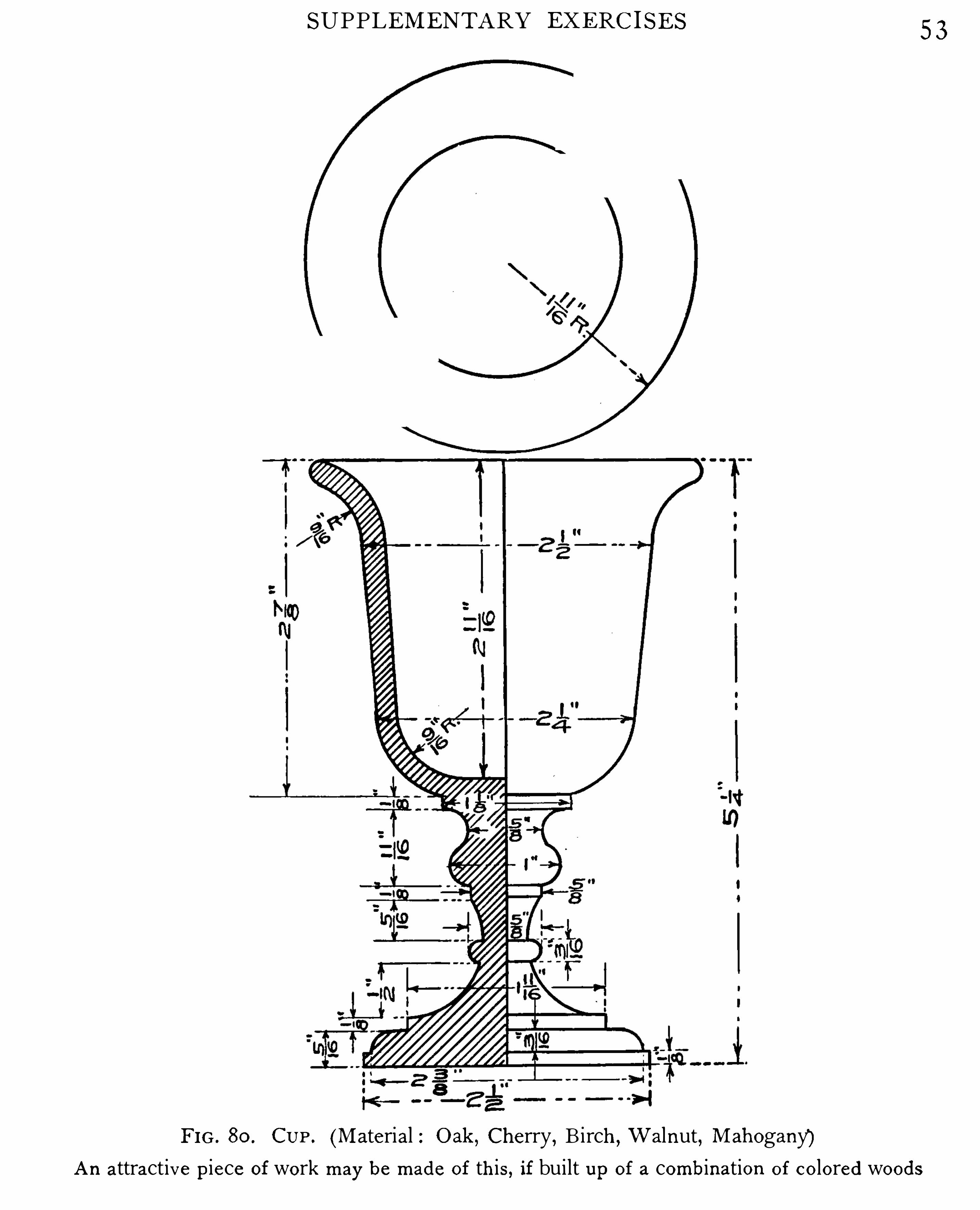
SUPPLEMENTARY EXERC I SES 5 3
FI G . 80 . CUP . (Material : O ak , Ch erry, B i rch , W alnut, Mah o gany)An attractive p iece o fwo rk m ay b e m ade o f th is, if built u p o f a co m b inatio n o f co lo red wo o ds

54WOOD TURNING
DUMB—BE LL . (Material : Map le)
Use a tem p let to wo rk b y

SUPPLEMENTARY EXERC I S ES 5 5
FI G . 83 . TU R N I N G TO O L H A ND LE S . (Material : H icko ry,Ap p le)
Lath e to o l h andles ar e o ften bro ken b y accident and m ust b e rep laced . I n turn ing a h andle, th e s izeo f th e tang o f th e to o l sh o uld b e taken into acco unt wh en p ro curi ng th e ferrule . T h e drawingsgiven abo ve ar e fo r h andles suitable fo r a " inch cut- o ff to o l , a - inch o r g - inch skew ch isel o r go uge,and a é - inch o r g - inch skew ch isel o r go uge . Fo r larger to o ls th e h andles sh o u ld b e increased a little
in diam eter b u t no t in length
WOOD TURNING
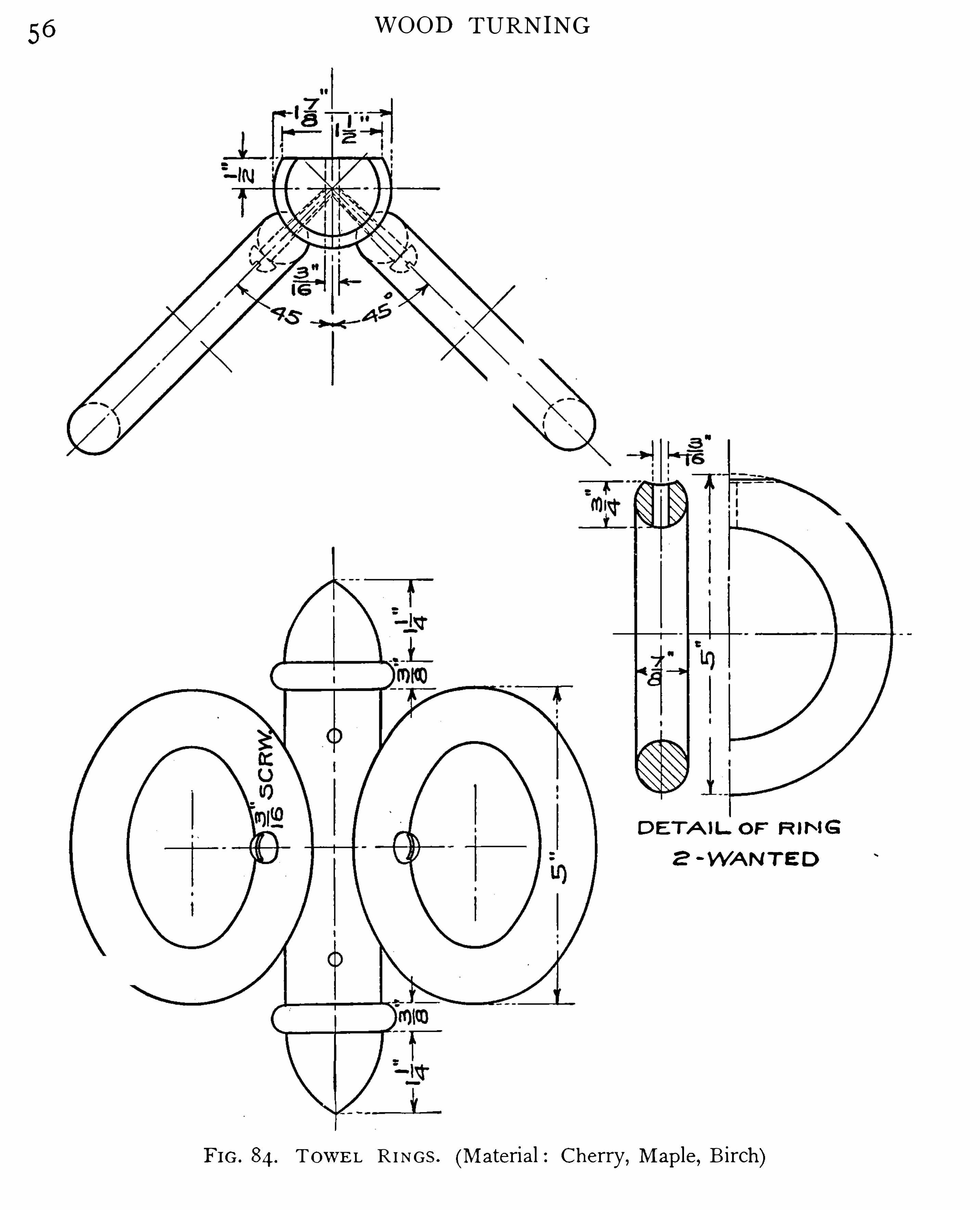
D E T A IL. O F"
R IN G
2 -WA N T E D
FI G . 84 .TOWE L R I N GS . (Material : C h erry, Map le, B irch )
SUPPLEMENTARY EXERC I S E S 5 7
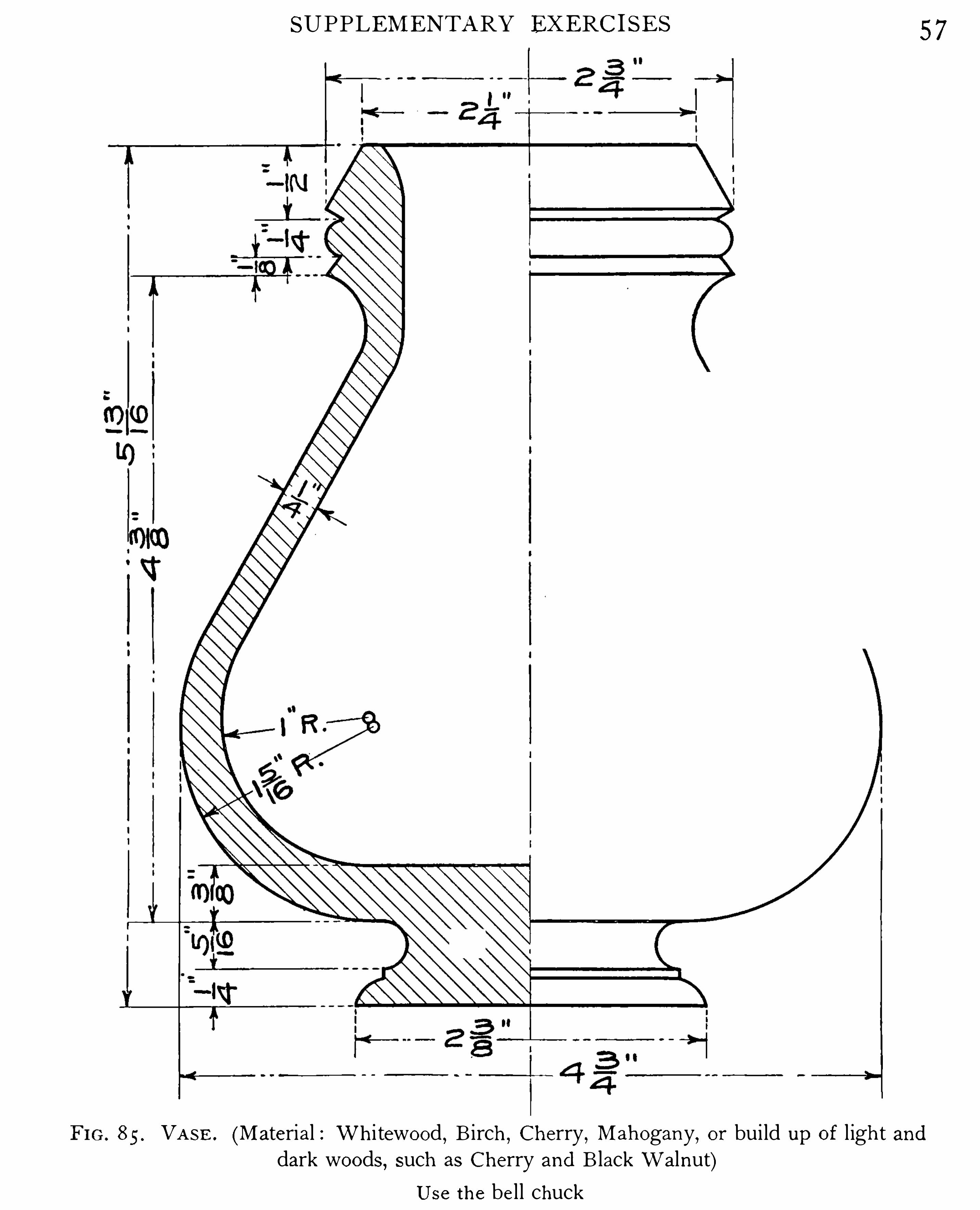
8 5 . VA SE . (Material : W h i tewo o d,B irch
,Ch erry , Mah o gany
,o r build up o f l igh t and
dark wo o ds,such as C h erry and B lack Walnut)Use th e bel l ch uck
WOOD TURNING
H ADE S UPPORT
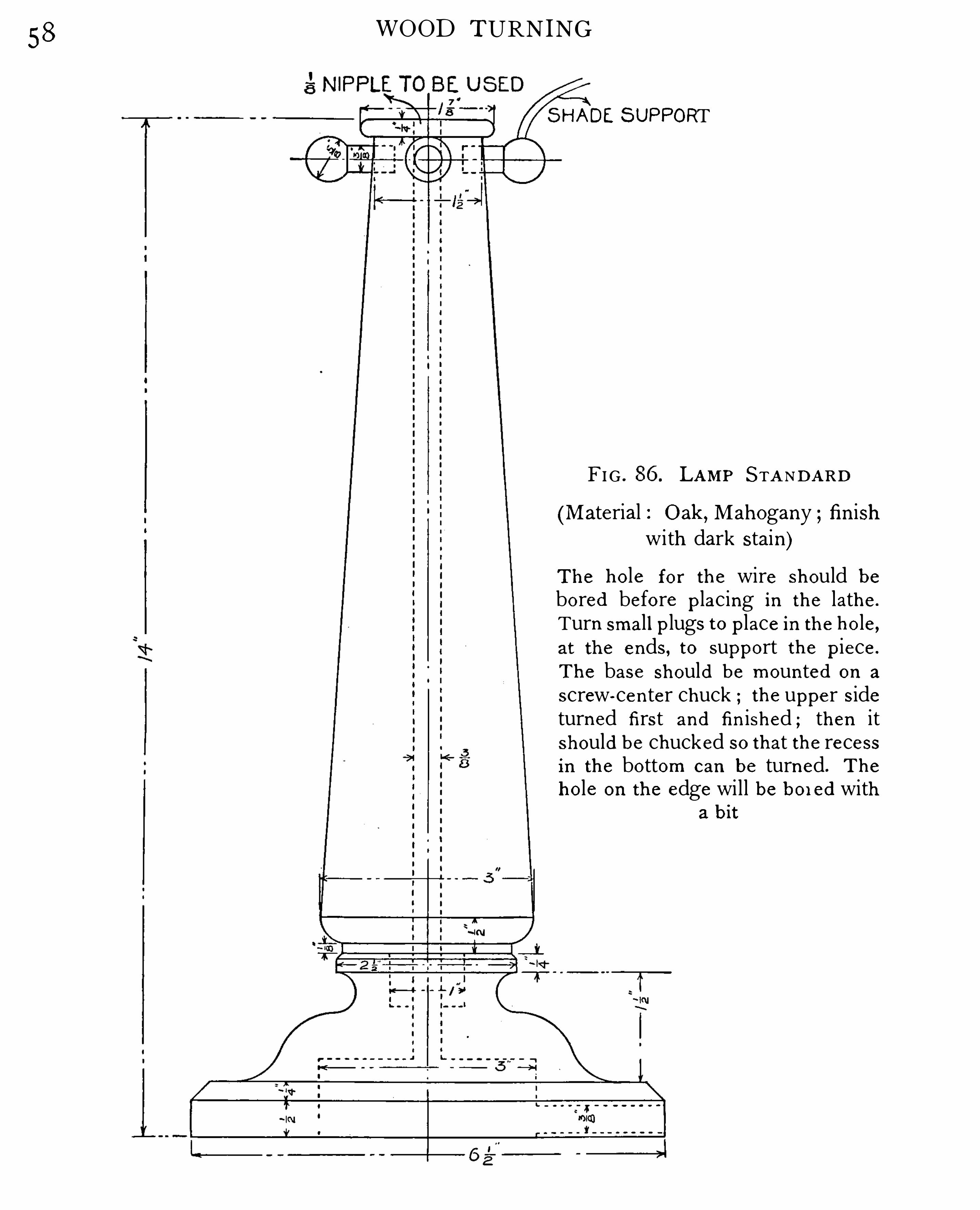
FI G . LAMP S TA NDAR D
(Material : O ak , Mah o gany ; finishwith dark stain)
T h e h o le fo r th e wire sh o uld b ebo red befo re p lacing in th e lath e.
Turn sm all p lugs t o p lace in th e h o le,at th e ends, to sup p o rt th e p iece.
T h e base sh o uld b e m o unted o n a
screw—center ch uck th e up p er sideturned first and fin ish ed ; th en itsh o uld b e ch ucked so th at th e recessin th e bo tto m can b e turned . T h e
h o le o n th e edge will b e b o i ed witha b i t

60 WOOD TURNING
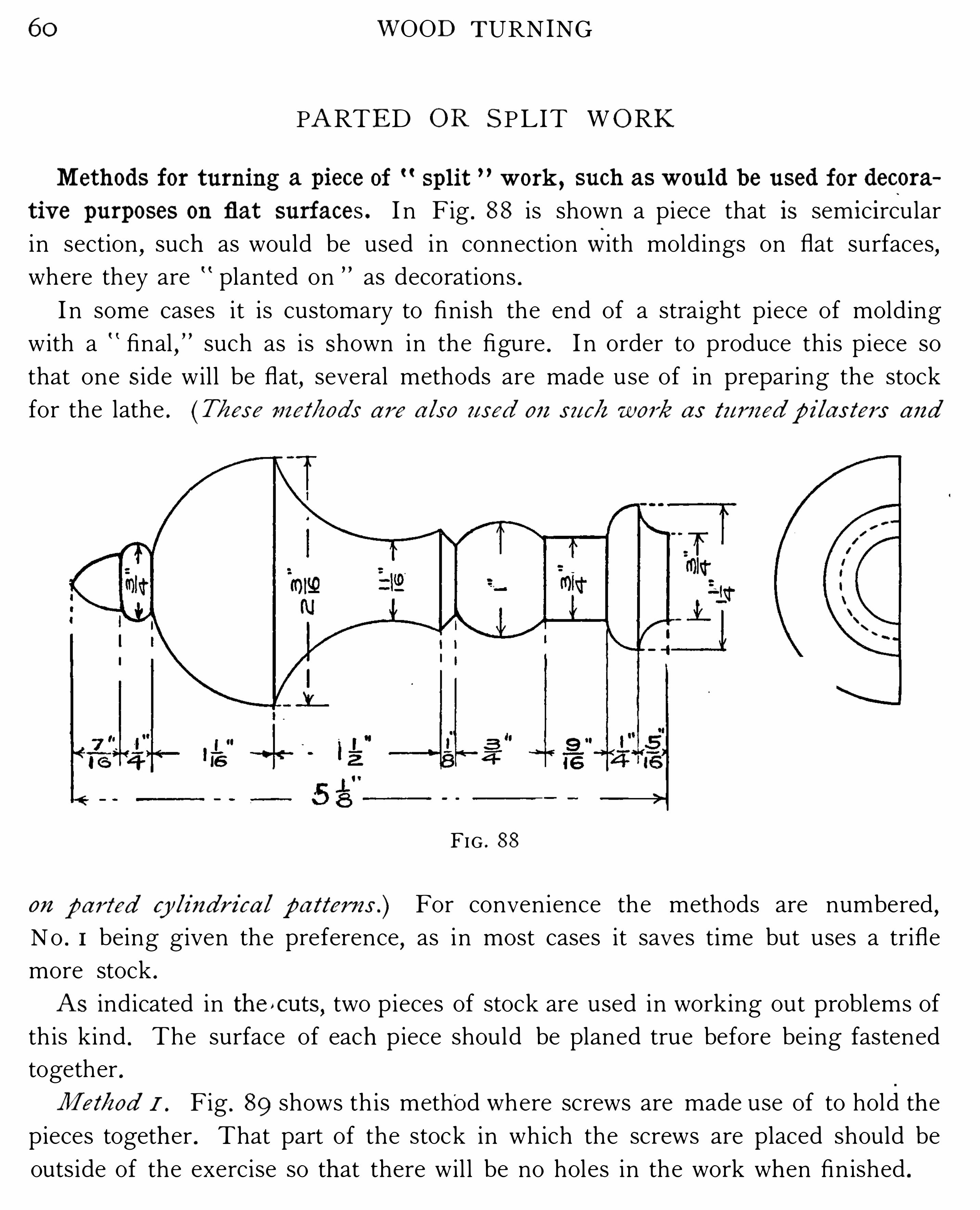
PARTED O R S PL IT WO RK
Meth ods fo r tur ning a p iece of sp l i t w o r k , such as w ould be used fo r deco r a
t ive p u r p o ses on flat surfaces . I n Fig . 88 is shown a piece that Is sem i c i rcular
in section,such as would be used in connection With moldings on flat surfaces
,
where they are planted on as decorations .
I n some cases it is customary to finish the end of a straight piece of molding
with a final,
” such as is Shown in the figure . I n order to produce th is p iece so
that one S ide wil l be flat,several methods are made use of in preparing the stock
for the lathe . (T/i ese m et/i o ds a r e a lso used o n suc/z w o r k as tu r ned p i laster s and
FIG . 88
on p a r ted cy lindr i ca l p a tter ns . ) For convenience the methods are numbered ,No . I being given the preference
,as in most cases it saves time but uses a trifle
more stock .
A s indicated in th e »cuts,two pieces of stock are used in working out problems of
th is kind . The surface of each piece should be planed true before being fastened
together .
Metko d I . Fig . 89 shows th is method Where screws are made use of to hold the
pieces together . That part of the stock in which the screws are placed should be
outside of the exercise so that there wil l be no holes in the work when finished .

PARTED OR SPL IT WORK 6 1
[Wet/zed 2 . I n Fig . 90 i s il lustrated th e m etho d where glue and paper are usedto hold the p ieces together . T h e glued surfaces should be outside of the exercise
as ind icated in the figure .
Metko d j . Fig . 9 1 i llustrates a m etho d wherecorrugated na il s ar e made use of,
and for very l ight work this m ethod is an excellent one .
Met/co d 4 . Fig . 9 2 i l lustrates a m etho d where p inch dogs are used , and in con
nect i o n with method No . I is often used o n heavy wo rk .
Met/zo d 5 . Where m uch of th is character of work is do ne,special attachments
are used on the lathe,which are practical and tim e- savers . T hese attachm ents can
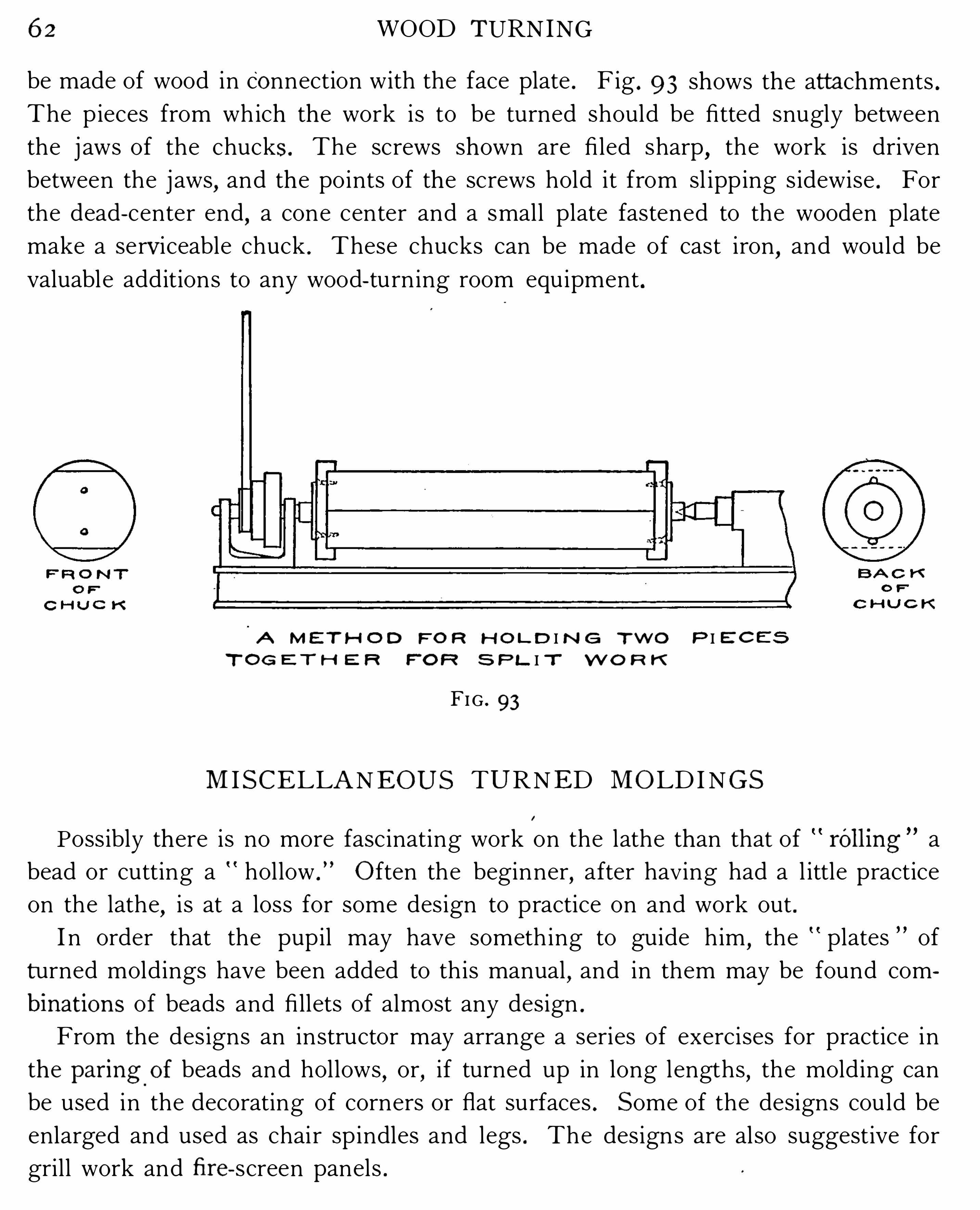
6 2 WOOD TURNING
be made of wood in co nnection with the face plate . Fig . 9 3 shows the attachments .
The pieces from which the work is to be turned should be fi tted snugly between
the j aws of the chucks. The screws shown are fi led sharp,the work is driven
between the j aws,and the points of the screws hold it from sl ipp ing s idewise . For
the dead - center end,a cone center and a small plate fastened to the wooden plate
make a serviceable chuck . These chucks can be made of cast iron,and would be
valuable additions to any wood- turn ing room equipment .
A M E T H O D FO R H O L D I N G T W O P I E C E S
T O G E T H E R F'
O F? S P L I T W O R K
FI G . 93
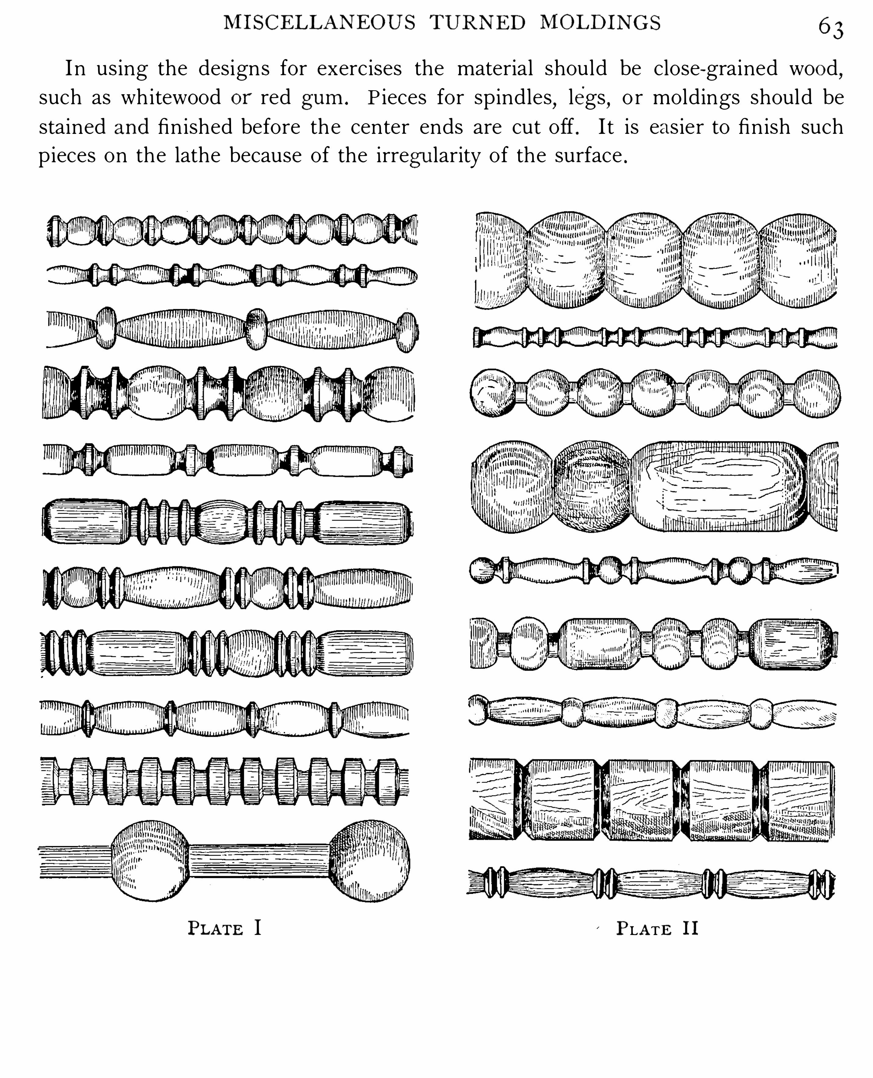
MI S CE LLA NEO U S TURNED MO LD I N G S
Possibly there is no more fascinating work on the lathe than that of rOlling a
bead or cutting a hollow . O ften the beginner,after having had a l ittle practice
on the lathe,i s at a loss for some design to practice on and work out .
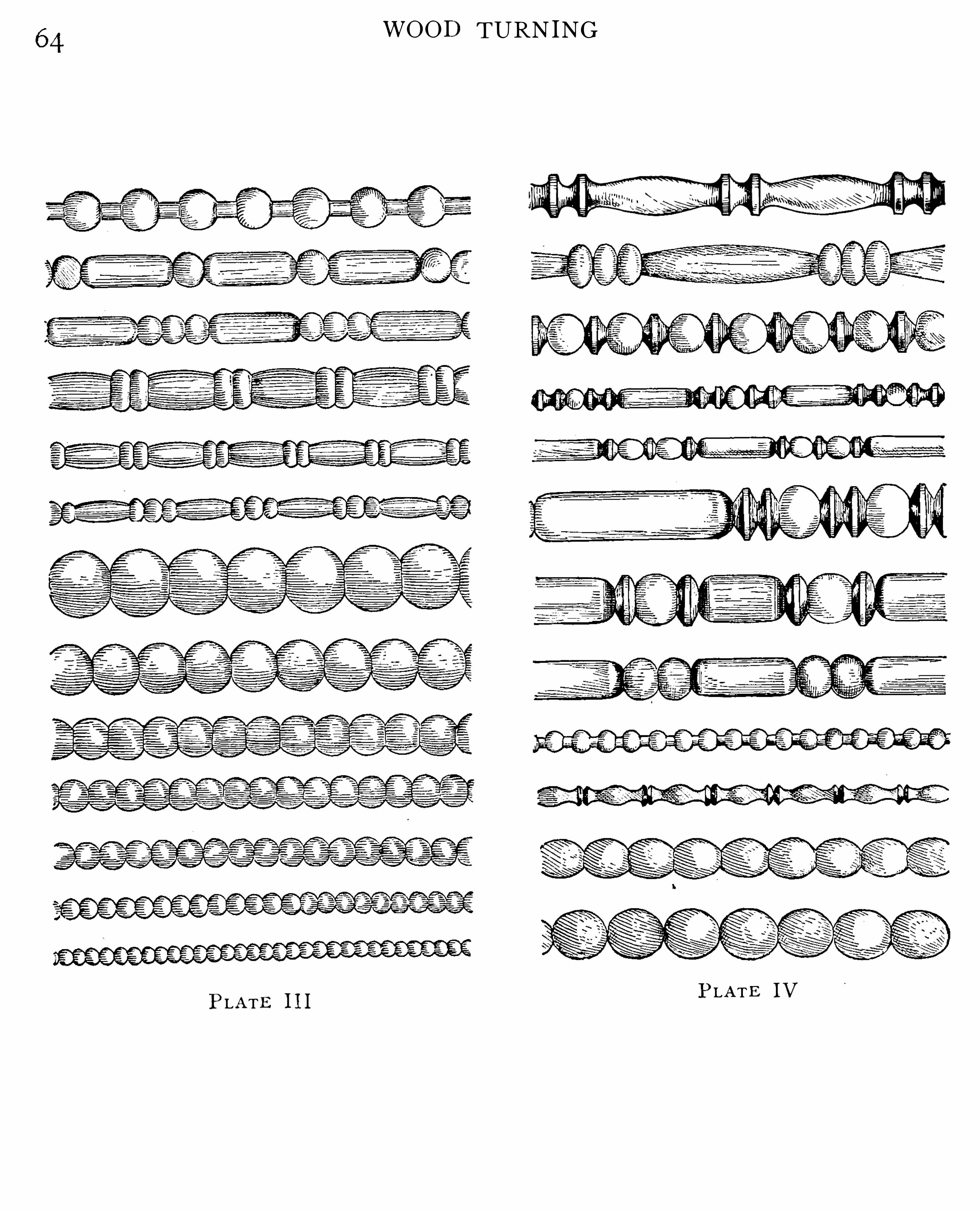
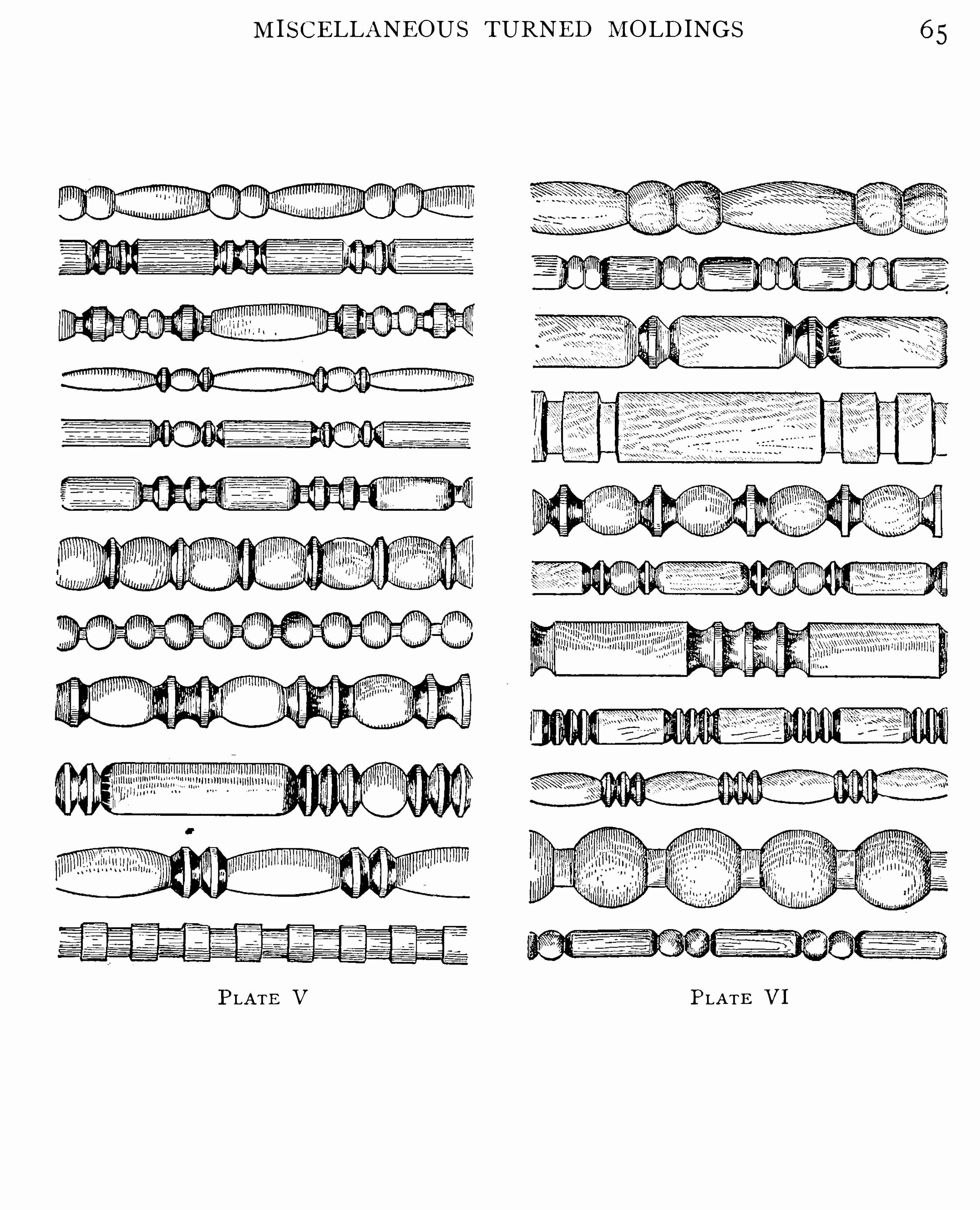
I n order that the pupil may have someth ing to guide him,the plates of
turned moldings have been added to th is manual,and in them may be found com
b inat i o ns of beads and fi llets of almost any design .
From the des igns an instructor may arrange a series of exercises for practice in
the p ar ing o f beads and hollows,or
,if turned up in long lengths
,the molding can
be used in the decorating of corners or flat surfaces . S ome of the designs could be
enlarged and used as chair sp indles and legs . The designs are also suggestive for
grill work and fi r e- screen panels .
h flSCELLAN EOU S'
TUR N ED Mf flI H N G S 6 3
I n using the designs for exercises the material should be close-grained woo d,
such as whitewood o r red g um . P ieces for spindles,legs
,o r moldings should be
stained and finished before the center ends are cut off . I t is eas ier to finish such
pieces on the lathe because of the irreg ularity of the surface .
PLATE I PLATE I I
WOOD TURNING
PLATE IVPLATE 1I I
M I S CELLANEOUS TURNED MOLD INGS
PLATE V PLATE V I


68 WOOD TURNING
This finish h as a quality that is greatly o verlo o ked ; nam ely,that i t is no t easily
"
m arked
w i th h o t dishes o r water.To fini sh w i th w ax. Finishing w ax can be ap p l ied o n alm o st any sta in,
o r it can beap p lied directly to th e wo o d . When it is rubbed do wn i t gives a dull g lo ss . I t is a ratherso ft finish
,is easi ly m arred
,but h as th e advantag e in that i t can be refinished witho ut
m uch tro uble.
Ap p ly th e w ax o n th e article with a clo th,let i t stand fo r a few m inutes
,then rub o ff
w ith a so ft clo th . T o p o l ish, use a fa i rly hard b rush . T o refinish , rep eat th e abo ve Op eratio n .
To m ake fini sh ing w ax. Cut beeswax into sm all p ieces, and, with twice as m uch tu rp entine as there is w ax
, p lace in a vessel and ap p ly a m o derate heat which w ill help to so ftenth e w ax.
Th e vessel s/zo u ld not be p laced over z‘fzefi r e.
T h e w ax sho uld be o f th e co nsistency o f vasel ine ; i f to o thick , thin with turp entine.
T o fini sh w i th sh ellac. In using shellac care sho uld be taken to see that th e so lutio nis no t to o th ick ; when to o thick , thin w i th alco ho l .In finishing a turned p iece, brush o n a fai rly heavy co at o f th e shel lac varnish ; then ,
while th e lathe is in m o tio n,rub th e surp lus o ff with a clo th
,befo re i t hardens . This will
g ive a g o o d finish fo r chisel handles and sim i lar articles.
O n flat surfaces th e shel lac sho uld be brushed evenly and no t to o heavy . T o o btain a
glo ssy surface, three co ats ar e necessary . A fter each co at th e surface sho uld b e sm o o thedwith fine sandp ap er (using N o . 0 0) befo re ap p lying th e next.T o rub a shel lacked surface
,u se fel t
,and rub down with p o wdered p um i ce and water.
T o po l ish th e surface o f a p iece o n th e lathe,use shellac and o i l
,being careful no t to use
an excess o f ei ther. A li ttle exp erience will determ ine th e exact am o unts.T o cut sh ellac. Put any quantity o f g um shel lac in a vessel (ei ther earthen o r glass
,
but no t z‘z'
fz o r i r on) , co ver i t o ver with alco ho l,st ir i t frequently . I t wil l take abo ut
fo ur to eight ho urs to reduce th e g um to liquid fo rm .
To li g h ten sh ellac. Shel lac wi l l beco m e dark co lo red when kep t in a tin o r i ro n vessel . T oclear it
,add abo ut o ne heap ing teasp o o nful o f o xal ic acid to a quart o f l iquid shel lac . I t is no t
advisable to use th e o xal ic acid o ften in th e sam e so lu tio n,as th e m ixture deterio rates .
To fini sh w i th var ni sh Usual ly a surface that is to be finished with varnish is firstfi lled (see Fi l ler) after staining, o r th e filler m ay be co lo red , thus staining and fi l l ingw i th o ne Op eratio n.
After th e surface is fi l led,th e p o res o f th e wo o d sho uld be sealed ; i t is fo und best to
seal them by ap p ly ing a co at o f shel lac. A fter th e shel lac is dry it is sm o o thed w ith sand
pap er, and then a co at o f varnish is p ut o n and al lowed to dry . (A m istake usual ly m adeo n varnished surfaces is
,that each co at is no t allowed to dry , sufficiently befo re the next

APPEND IX 69
co at is ap p l ied . ) Befo re p utting o n a fresh co at o f varnish th e surface sho uld be sm o o thedwith ei ther N o . 00 sandp ap er o r ha i rclo th.
When th e required num ber o f co ats ar e sp read o n th e wo rk and dried suffi ciently,th e
surface can be left glo ssy , o r i t can be rubbed w i th p o wdered p um ice and water,giving
an eggshel l glo ss,o r i t can be p o l ished . T o p o l ish , rub with p um ice and water
,then
p o l ish by rubbing wi th ro tten sto ne,finally using finely p o wdered cha lk . G ive th e surface
a final rubbing with th e bare h and'
and clean o ff with a p iece o f Cham o is sk in o r so ftsi lk . A l i tt le exp erience is necessary to determ ine h o w m uch rubbing is requ ired . T h e
co nditio n o f th e wo rk wil l usual ly determ ine this .
Fi llers . Ready- to -use fil lers can be o bta ined in th e o p en m arket ; they save tim e.
Many m ateria ls a r e used as a base in th e m ak ing o f fil lers,such as whi ting
,co rnstarch,
si lex,flo ur
,etc. T h e m aterial which w e bel ieve to be th e best is si lex .
T o m ake l ig h t fi l lers . T o m ake th e fil ler,take a quanti ty o f si lex and m ix i t with lin
seed o il into a stiff p aste ; then add a sm al l quantity o f "ap an drier in th e p ro p o rtio n o f o ne
tablesp o o nful to o ne quart o f p aste. M ix tho ro ughly,thin to th e p ro p er co nsistency with
turp entine o r benz ine,and ap p ly with a brush ; let i t set
”
fo r a tim e,then rub o ff with
excelsio r o r burlap , and finally rub with waste o r a so ft clo th . T h e fil ler sho uld be left to dryfo r at least twenty- fo ur ho urs befo re th e first co at o f shel lac is ap p l ied .
To co lo r filler . A go lden o ak stain and fil ler is m ade by adding to th e abo ve r aw siennaand a l i ttle burnt um ber. A dark fil ler is m ade by adding to th e l ight fil ler burnt um berand dro p black . A green fil ler is m ade by adding to th e l ight fil ler chro m e yel lo w and Prussian blue. A lm o st any shade o r co lo r can be h ad by using co m binatio ns o f p igm ents withth e l ight fil ler.S ta ins . In using chem icals to sta in wo o ds i t wil l be fo und tha t different p ieces o f th e
sam e k ind o f wo o d will take different shades ; esp ecial ly is this true in regard to o ak .
T o o btain an o live g r een on o ak,u se a saturated so lutio n o f i ro n chlo ride. When th e
wo o d co m es o u t l ight a so lutio n o f tanni c acid wil l darken i t. "udgm ent m ust be exercisedin th e use o f th e tannic acid in resp ect to th e strength o f th e so lutio n. This will dep endo n th e hardness and co lor o f th e wo o d . D ifferent shades o f green can be h ad by differentstrengths o f so lutio n.
T o o bta in a r ide deep b r ow n on o ak,use i ro n chlo ride, and o n tha t ap p ly am m o nium
sulp hide. I f p ieces in th e wo rk sho uld be l ighter, use tanni c acid to darken.
T o co lo r zo /zz'
i ezo o o o’a deep br ow n
,fi rst give a co at o f tannic acid (five p er cent so lu
tio n) , then a co at o f i ro n chlo ride,then am m o nium sulp hide. T reat ash in th e sam e m an
ner (fo r bro wn) as whi tewo o d .
T o da r ken m o /zog o ny ,use a five p er cent so lutio n o f bichro m ate o f p o tash . This wil l
ag e it. When th e bichro m ate so lutio n is dry o n th e wo rk , co at with a so lutio n o f r ed

o WOOD TURNING
sanders. B ichromate solutio n is made fro m the crystals dissolved in water. Th e dep th o f
colo r requ ired will determ ine the streng th of th e so lutio n. R ed sanders so lutio n is m adeby extracting th e co lor from the p o wdered r ed sanders in alco ho l . Th e dep th o f co lo rrequ ired w i ll determ ine th e streng th o f so lutio n.
T o p ro duce an o ld m akog any sta in o n m aho g any and cherry,co at th e wo rk w i th a so lu
tion o f b ichro m ate o f p o tash or am m o nia , and, when dry, give it a co at o f fil ler m ade in
th e fo llo w ing m anner
T o m ake m a h og any fi ller , add - ro se lake and dro p black to light filler,and ap p ly th e
sam e as o rdinary filler.T o da r ken o ak
,use co m m o n l im e
‘
m ade into a thin p aste and ap p ly . Let it stand a few
m inutes and rub o ff ; if no t dark eno ugh,rep eat th e o p eratio n .
A rich br ow n is o btained by th e use o f iro n chlo ride,am m o nium sulp hide, and burnt
um ber. T h e um ber is m ade by m ixm g so m e o f th e p o wder in l inseed o il and turp entine,o r th e um ber g ro und in o il
,th inned w i th tu rp entine, can be used. Ap p ly in th e o rder
g i ven abo ve.
All wo rk sho uld be rubbed o ff with a so ft clo th after o il o r o il stain is ap p l ied . O n all
wo rk where water o r sp i rit stains ar e used, an o i l- sta in effect can be o bta ined by co atingwith linseed o i l.
Fum ing oak and o th er w oods . T h e effect o f fum ing with am m o nia is different o n differ
ent woods (a l ittle exp erim ent ing by th e p up i l wi ll be o f interest) esp ecial ly is this trueo f o ak. R ed o ak w ill no t give such go o d results as whi te o ak
,and so i t is wi th o ther wo o ds.
In fum ing,th e wo rk sho uld be free fro m all grease o r o il sp o ts. T h e surfaces that ar e
to be stained sho uld be kep t clear o f all o ther su r faces, to allo w free circulatio n o f th e
fum es of th e am m o nia .
T h e wo rk is p laced in an ai r - tight b ox ; an o p en vessel co ntaining am m o nia is also p laced
in the b ox with th e article. T h e wo rk is left until th e desired co lo r effect is o btained ;a beautiful so ft stain is th e result.
T o stain wo o d klaek, brush th e wo o d o ver severa l tim es with a h o t so lutio n o f lo g w o o d,and
,when dry
,ap p ly a co at o f a p rep aratio n m ade fro m p o wdered gal ls. Finish with w ax.
T h e lo g wo o d so lutio n is m ade by bo i l ing th e lo g w o o d in water. T h e ga l l so lu tio n is m adeby us ing tw o ounces o f p owdered g a lls to o ne quart o f water. T h e g al ls sho uld be allowedto stand in the water fro m three to fo ur days ; a m i ld heat sho uld be ap p lied duringthis tim e.
Another m ethod o f ebo niz ing wo od is to g ive the wo rk a co at o f extract o f lo g wo o d (theho tter th e better) , and, when dry, ap p ly a co at o f acetate o f iron (which is m ade by p uttingiro n filing s in vineg ar o r in a five p er cent so lutio n of acetic acid) . After th e seco nd coat isdry, ap p ly a co at o f a solution made o f sulp hate o f iron (tw o ounces to a quart o fwater) .

APPENDIX7 I
A th i rd m etho d o f ebo niz ing wo o d is to ap p ly three o r fo ur co ats o f ex tract o f lo gwo o d ;develo p th e co lo r by go ing o ver th e wo rk with a tincture o f m uriate o f i ro n.
A no Z/zer m et/10d of ebo n i z i ng w o od. B o i l o ne hal f p o und o f lo gwo o d in tw o quartso f water
,add to this th e p eel o r shel ls o f walnuts
,weighing abo ut fo ur o unces. Bo i l a
seco nd tim e and stra in,then add o ne half p int o f go o d v inegar and ap p ly to th e wo rk
when h o t .
Ani line stains . Fro m ani line dyes alm o st any co lo r and shade can be o btained byco m binatio ns. S o m e o f th e co lo rs ar e so luble in alco ho l
,so m e in water
,and o thers ar e
so luble in ei ther water,alco ho l
,o r turp entine.
In m i x ing fo r d ifferent shades,therefo re
,th e liquid in whi ch th e co lo r is so luble wi l l
determ ine which can be m ixed to gether. S o m e o f th e co lo rs require a m o rdant,and a so lu
tio n o f alum,v inegar
,o r co p p eras m ay be used .
T h e m etho d o f m ak ing a m aho gany ani l ine stain is as fo llo ws : bism arck bro wn, 5 o z .
bo i ling water, 3 p t . ; o r bism arck bro wn
, 5 o z . ; alco ho l , 3 p t .All o th er ani l ine stains ar e m ade in this m anner
,substi tuting th e l iquid in which they
wi l l disso lve. Ani l ine stains sho uld be kep t in bo ttles, labeled , giv ing strength o f so lutio n
(water, al co ho l , o r o il) , so that no m istake can be m ade in using it .Mi scel laneo us r eci p es . I . Makog any . Fu st ic ch ip s , 2 o z . ; m adder ro o t
,lb . ;
water, g al.
2 . Ma izog any . Disso lve archi l in water and m ake i t o f such strength as wil l sui t ; add
a l i ttle eo sin,and ap p ly to th e wo rk co ld .
3 . [Il a/zog any . B o i l lo g wo o d chip s in twice thei r bulk o f water fo r tw o h o urs. S train,
then add a sm al l quanti ty o f chlo ride o f t in . T h e t in gives redness. T h e quanti ty o f tin
to be used wil l dep end up o n th e co lo r required . G ive th e wo rk tw o co ats.
4 . Wa/nnz‘
. Ep so m sal ts, o z . ; p erm anganate o f p o tash , o z . ; water , p t . D isso lve,
strain,and ap p ly ; rep eat unti l dark eno ugh to sui t .
5 . Wa lnnf. V andyke bro wn, 4 o z . ; lye o r p o tash , 2 o z . ; water, 1 ; lb . B o i l unti l th e
bulk is reduced to less than hal f,and ap p ly with a clo th when co ld .
6 . Wa lnut. V andyke brown,I o z . ; burnt um ber , "z3 o z . ; aqua am m o nia
, " lb . Mixand
ap p ly after stra ining. Let th e wo rk stand fo r a t im e to g et rid o f th e am m o nia fum es.
7 . To m ake a r osew o od sla in . Bo i l o ne quarter o f a p o und o f lo gwo o d in o ne and o ne
hal f p ints o f water , then add o ne quarter o f an o unce o f sal ts o f tartar. S tain th e wo rkwith this so lutio n whi le i t is h o t. G ive tw o o r three co ats. T o develo p th e grain o f ro sewo o d
,take a stiff brush and streak with th e ebo ny sta in p revio usly described , using a p iece
o f ro sewo o d as a p attern fo r th e grain.
8 . R osew o od. Any o f th e m aho gany sta ins w i l l m ake a ro sewo o d stain i f rep eatedly
ap p l ied. I f stained to a dark m aho g any to ne, g o o ver th e wo rk l ightly with an ebo ny stain,

7 2 WOOD TURNING
using a cam el’s-hair brush . G o o ver th e w o rk in a straggling,hap haz ard w ay , which is p eou
liar to th e grain o f ro sewo o d .
9 . Cker ry . Any o f th e m aho gany stains will m ake a cherry sta in if thinned .
I O . D a r k oak. Burnt um ber, 4 o z . aqua am m o nia sufficient to m ake stiff p aste. Thin
unt i l th e desi red shade is o btained .
I I . To br ag /den sfa z'
ns. N i tric acid, l; o z . hydro chlo ric acid
,o z . gra in t in
, 5 o z . ra inwater
,I o z . This sho uld be m i xed a few days befo re using .
1 2 . A beauti ful brown is o btained o n whi tewo o d and birch by using,first
,extract o f
lo gwo o d,al lowing i t to dry
,and then adding a co at o f acetate o f i ro n . Rub o ff with a so ft
clo th and finish with w ax.
R eci p e fo r r efini sh ing var ni sh ed sur faces . In sta in i ng and finishing wo o ds a student isl iable to m ake m istakes in th e co lo r wanted . Many tim es
,i f th e wo rk co uld be refinished
,
i t wo u ld ‘
be m o re satisfacto ry to h im .
T h e fo llo w ing recip e fo r cleaning Off varnish and fi ller,and bleaching th e wo o d to i ts
natural co lo r,w i l l be fo und to give very satisfacto ry results
C lean o ff shel lac and varnish w i th varn ish rem o ver. V arn ish rem o ver is o bta ined inth e Op en m arket fro m dealers in p aints and varnishes.After th e surface h as been cleaned o f varnish
,wash i t o ff with a stro ng so lutio n o f caus
t ic p o tash o r lye ; then wash o ff with clean co ld water ; then wash o ff wi th th e bleachingso lutio n
,wh ich is m ade o f o xal ic acid
,a stro ng so lu tio n. Let this dry and wip e o ff with a
dam p clo th, wh en th e surface w i l l be ready to stain and finish in any desirable w ay .
Ano ther so lutio n which w i l l rem o ve varnish and m ay be m ade by th e student wi th l i ttledifficu lty is p rep ared in th e fo llo w ing w ay : M ix to g ether equal p arts o f so ap p o wder o r
Go ld Dust and caustic so da,add to this abo ut o ne quarter as m uch am m o n ia as there is
p owder, then add water eno ugh to disso lve th e p o wder. Ap p ly to th e varnished surfacewith a clo th ; wip e o ff th e o ld varnish w ith burlap o r excelsio r and finish wip ing w i th a
clean clo th. (T h e hands sho uld be p ro tected . ) B leach th e surface with th e o xal ic acidso lutio n. S tain and finish in any desi rable w ay .
A m eth od of deco r at ing w o r k w i th desi g ns on l i g h t-co lo r ed w o ods . Draw th e desi reddesign o n th e wo rk . S hel lac th e design
,being careful to keep th e edges sharp . G ive tw o
o r three co ats,and after each
,sm o o th th e surface with fine sandp ap er. When th e shel lac
h as tho ro ughly hardened,ap p ly a co at o f any desi red dark sta in to th e who le wo rk ; th e
design will stand o u t l ike inla id wo rk .
Cem ent w ax used i n tur ning . A cem ent used in tu rning ,to ho ld l ight and thin p ieces o n
th e lathe,is m ade as fo l lo ws : resin
,I o z . ; p i tch, 2 o z . ; r ed o cher, finely p o wdered . Mel t
th e resin and p i tch to gether, and , whi le bo i l ing , add th e o cher. U se eno ugh o f th e o cherto m ake th e cem ent o f th e p ro p er co ns istency ; a l i t tle tal low is so m etim es added to this .

APPEND IX 7 3
By ap p lying this cem ent to a chuck and heating it,a thin p iece o f wo o d can be held
wh ile being turned o n th e lathe. T o rem o ve th e p iece fro m th e chuck,tap i t lightly and i t
will co m e o ff with l i ttle tro uble.
Ano ther rec i p e fo r cem ent w ax is : resin ,I " lb . ; p i tch , 4 o z . Mel t to gether
,and
,whi le
bo il ing,add brick dust ; test i t by dro p p ing a li ttle o n a flat surface until i t is fo und to
'
be
hard eno ugh ; then p o ur it into water and m ake u p into ro l ls.
S til l ano ther m ay be m ade by m el ting equal p arts o f resin and beeswax to gether and
al lowing to co o l,when i t will be ready fo r use.


76
Lateral m o tio n, 4Lath e to o ls, 1 2L ine sh aft, 6 ; revo lutio ns o f, 6
Live center , 4L ive- center end , 1 7Live sp indle, 4Lo gwo o d, so lutio n o f, 70
Lo o se p ulley, 6
Mah o gany fi ller, to m ake, 62Mah o gany, to ag e, 69Mal let, t o turn , 34 ; to wo rk o u t ,
3 5Ma l let h ead, to lay o ut fo r h o le,3
Meassu r ing to o ls , 1 2
Meth o d, o f grinding, 13 ; o f
h o lding skew, 20 ; o f m o unti ng wo rk fo r face-
p late turning , 28
Mo ldings, m iscel laneo us , 62Mo rdant, 67Mo tio n o f ch isel , to cut ends, 2 1Mo to r h ead lath es, 7Mo to r-driven lath e, 1 1Mo unting wo rk fo r center turning , 18
N am es o f p ieces t o des ign. 46
N um ber o f rev o lutio ns, o f l i nesh aft, 6 ; o f grindsto ne, 1 3
O ak , t o da r ken , 70
O b tuse angle, 16
O i l cup s, 4O i l stain , fo r brown , 70
O i l, to finish w ith , 47O i l, to , 4O i lsto ne, 1 7O ld m ah o gany, to stain fo r , 70O rd inates, to turn b y , 48O utside cal ip ers , 16O verh anging sp indle, 8
Pap er, to m o unt wo r k with , 39Paring cut, 19Parted wo rk , t o turn , 50
Parting to o l , 16
WOOD TURNING
Patterns , m eth o ds used in tur nIng , 33
Plate, to tur n, 50
Po l ish with sh el lac , 24Po res, to seal , 68Po sitio n, o f th e bo dy, 19 ; o f th eh ands, 19 ; o f th e ch isel o n
grindsto ne, 1 5Powdered ch alk , 69Prim itive lath es, 1—3Pro j ects selected, 48Pum ice sto ne, p owdered, 69
" uarter- inch skew ch isel 28
R aw sienna , 69Ready- to - use fi l lers, 69Receiver, card , 45Reci p e fo r rem o v ing varn ish ,
7 2
Recip es , m iscel laneo us, 7 1Rem o v ing wo rk fro m face p late,
4 1
R ings, nap kin, 36 ; to turn, 42 ;
towel, 56R o d , 4Ro l l ing p in , t o turn , 43Ro sewo o d, sta in fo r , 7 1Ro tten sto ne, 69Ro ugh ing down , 18
Ro und- no se scrap ing to o l , 1 5Rubbing a surface, 69Rule, m easuring, 16
Rules fo r sp eed o f grindsto ne,
I 3
S andp ap er, to use, 23S crap ing cut, 19 ; instructio nsfo r , 18 ; t o set rest fo r , 2 6
S crew-center ch uck , 4S crew-ch uck turning, 26S crew h o les, t o el im inate, 4 1S ecti o n (see R ing) , 43S elf- co nta ined lath e, 7S h arp en ing go uge, 14S h ar p ening to o ls, 1 2S h arp ening th e skew, 1 5S h ifter, 3—7
S i lex , 69S iz es , o f ch isels and go uges, 16 ;o f driv ing p ulleys , 7
S iz ing, 24S iz ing to o l , 16S kew ch isel , t o h o ld, 19S kewed, 14S l ide rest, 9S l ip sto ne, 1 7 ; sh arp ening with ,
14S m eary surface fro m sh ellac , 2 7S m o ker set, 40S o ft si lk , to p o l ish with , 69S p eed lath e, th e, 3
—7
S p eed o f grindsto ne, 13S p indle, ta il sto ck , 5 h eadsto ck , 4
S p l it wo rk , m eth o ds fo r , 60 ; at
tach m ents fo r turning, 62S quare-no se scrap ing to o l , 1 5
Tabulated drawing, 34Tai l sto ck , 4Tannic acid, 69Tem p er, draw, 2 1.
Tem p let, fo r ch isel h andle, 2 5 ;to m ake, 30
Tem p lets, to ap p ly,Tigh t p ulley, 7To o l rest, 6To o ls used in turn ing, 4—1 2
Um b er, burnt, 70Using th e go uge, 18
Varn ish , t o finish with , 68
Varnish ed surfaces , t o refinish ,
7 2
Vase, 57
Wa lls, th ickness o f, 28
Wa lnut, sta in fo r , 7 1Wax, adh esive, 7 2 ; fin ish ing,67 ; to ap p ly, 3 1 to m akefinish ing, 67
Wh itewo o d, to stain brown, 67t o treat fo r brown, 69
W h iting, 69