wireless communication with mobile inspection robots
TRANSCRIPT
Wireless communication with mobile inspection robots
operating while submerged inside oil storage tanks
Richard Anvo1, Aman Kaur 2 and Second Tariq P. Sattar 2
1,2,3 London South Bank University Innovation Centre, London, UK
Abstract. Data acquisition during storage tank inspection is one of the most important aspects
for petrochemical storage tank owners. Mobile inspection robots designed to enter inside a
storage tanks without taking the tank out of service are required to enter through manholes on
the roof of the tank with openings as small as 300-millimetre diameter. These robots are con-
trolled via an umbilical cable which supplies power to the robot, sends and receives signals to
control robot motion, and transfers inspection data acquired by non-destructive testing (NDT)
sensors back to NDT inspectors. It is important to localize a robot inside the tank so that NDT
data indicating a defect such as corrosion pitting in tank floors or weld cracks can be mapped
for subsequent monitoring and repair. Wireless communication with the robot for NDT data
acquisition and localization would enable the minimization of umbilical size and its effective
management which is important when a small mobile robot is supplied with a very long umbili-
cal. This paper presents results of a study to develop a wireless communication system that uses
radio frequency (RF) signals with low power (< 1W) sent by a transceiver on a robot operating
inside an oil storage tank which travel through an oil medium, are transmitted through steel
tank walls and are captured by receivers placed in air outside the tank. Simulations using Feko
software have been performed to assess the feasibility of using RF for communication in oil
storage tanks with laboratory experiments conducted using vegetable oil to validate the simula-
tions. RF signals transmitted by a robot operating inside an oil tank and received by a number
of receivers placed in air around the tank has potential application as a robot localization sys-
tem.
Keywords: Storage tank inspection, EMW, NDT, In-service inspection.
1 Introduction
Several in-service storage tank inspection robots have been developed over the last
decade [1], [2] for the purpose of storage tank inspection. During normal inspection
operation, these robots gather non-destructive ultrasonic data and are powered via an
umbilical cable. However, managing their umbilical cable (>100m) could introduce
significant problem because most storage tanks contain some heating coils and roof
legs support which make a robot less free to move around to inspect the tank floor
corrosion.
Radio Frequency (RF) is a promising technology for many wireless applications
due to its large bandwidth, a good ratio of transmission data and low cost. All in-
service inspection for petrochemical storage tank robot explored so far have used
Corresponding author: Richard Anvo
2
cables for robot control and NDT data transmission [3], [4], [5], [6] and [7]. Using
very low power with low-frequency RF communication in this environment would be
a critical forward step to the widespread uptake of in-service inspection robots be-
cause it would eliminate the inspection challenges associated with heating coils and
tank roof supports as well as data transmission and for robot localisation. Currently,
no work on Radio Frequency communication for in-service inspection robots in pet-
rochemical storage tanks has been published. Associated research on underwater
wireless communication is reported in [8], [9] and [10]. Wireless applications for the
oil and gas industry past and present methods of communication in oil and gas have
included satellite communication (on a limited basis), cellular and specialised mobile
radio, fibre-optics, and general offshore telephone service using radio frequencies
[11].
So far, all RF devices are designed to work in the air and tested in water environ-
ments. However, this paper presents an investigation of radio frequency communica-
tion in petroleum media and vegetable oil. Experiment and simulation with commer-
cial electromagnetic software, FEKO and Multiphysics COMSOL 5.4 were used to
test and to analyses the attenuation of electromagnetic wave (EMW) propagation in
petroleum products and vegetable oil. Section 2 of this paper describes electromagnet-
ic wave absorption with media parameters, section 3 calculation of electromagnetic
path loss in petroleum and vegetable oil, section 4 simulation results of the EMW
propagation, whilst section 5 describes experimental EMW data transmission in vege-
table oil, followed by conclusions and future work in section 6.
2 Electromagnetic wave absorption and dispersion through
petroleum products and other medium
The propagation of an electromagnetic wave through matter is governed by three
proprieties of the material: conductivity (σ), permeability (μ) and permittivity (ε) or
dielectric constant. These parameters' changes with the medium and the electrical
conductivity value associated with the medium often vary. Therefore, the wave prop-
agation speed and absorption coefficient, which are directly related to the working
frequency, also vary. The electromagnetic wave absorption and dispersion for wave
propagation through medium is calculated using equations (1) and (2). Table 1 shows
the absorption and dispersion of EM waves with given petroleum medium, air, sea-
water and vegetable oil.
α = ω√με
2[√1 + (
σ
ωε)2- 1] (1)
𝑘𝑑 = 𝜔√𝜇𝜀0𝑘 (2)

3
The dispersion of the Electromagnetic Wave (EMW) varies with the frequency Table
1, a higher frequency means strong scattering of the wave and less travel distance.
However, the absorption of EMW in Vegetable oil, Gasoline and Kerosene is zero,
therefore, there is no resistance to EMW propagation due to their very low electrical
properties. The dielectric constant is the most critical factor that affects the propaga-
tion of petroleum. Their properties are a function of temperature, so the increase in
temperature leads to an increase of attenuation during communication in petroleum.
Another factor that could affect the signal depends on water concentration in the pe-
troleum product. The increasing water content will increase power loss. The selection
of the optimal RF frequency is an essential factor for realising robot ultrasonic sensor
data transfer or robot localisation in a storage tank. Selecting higher frequency than
the optimal will increase the attenuation due to wave absorption and limit the distance
of propagation.
Table 1. EMW absorption and dispersion in a given medium
Frequency Medium Vegetable
oil
Gasoline kerosene
433 MHz
Absorption(N/p) 0 0 0
Dispersion(rad/s) 15.97 12.83 11.83
300 MHz
Absorption (N/p) 0 0 0
Dispersion(rad/s) 11.08 8.89 8.20
250 MHz
Absorption (N/p) 0 0 0
Dispersion(rad/s) 9.22 7.40 6.83
200 MHz
Absorption (N/p) 0 0 0
Dispersion(rad/s) 7.38 6.63 5.46
3 Calculation of propagation path loss in petroleum and
vegetable oil
The path loss is a significant component in analysis and design a telecommunication
system. It is the reduction in the power density of the electromagnetic wave as it
propagates through the medium. The path loss is calculated using equation (3), the
medium is known as a dielectric.
𝑳𝒑𝒂𝒕𝒉 𝒍𝒐𝒔𝒔 (𝒅𝑩) = 𝑳𝟎(𝒅𝑩) + 𝑳𝒘(𝒅𝑩) + 𝑳𝒂𝒕𝒕(𝒅𝑩) (3)
Where Lo(dB) path loss in the air, Lw (dB) is path loss due to the medium change and
Latt (dB) is path loss due to attenuation in the medium. The attenuation constant α = 0,
therefore, the path loss becomes:

4
𝐿𝑝𝑎𝑡ℎ 𝑙𝑜𝑠𝑠 (𝑑𝐵) = 𝐿0(𝑑𝐵) + 𝐿𝑤(𝑑𝐵) (4)
The effect of frequency on the path loss at a distance of 1 m between the transmitter
and receiver antenna is illustrated in Fig. 1, which shows that as the frequency in-
creases the path loss also increases. Path loss increased in vegetable oil compared to
gasoline and kerosene fuel due to its high dielectric constant.
Fig. 1. Path Loss as a function of frequency for Vegetable oil, Gasoline and Kerosene
4 Simulation results of electromagnetic wave propagation in
different mediums
4.1 Simulation results 3D radiation pattern
The software used in this design simulation was the popular commercial electro-
magnetic software FEKO. A dipole antenna was designed with a 433MHz. To simu-
late electromagnetic propagation in the medium, a box cube with a size of 4 x 4 x 4
meters was used to represent the medium in which the electromagnetic wave will
propagate, see Fig. 2. The simulation involved four different types of medium based
such as diesel fuel, jet fuel, vegetable oil and water. The antenna was placed in the air
at 3 meters away from the medium represented by the box cube.
Fig. 2. A 3D view of the dipole with a cube (medium) model.

5
Fig. 2 shows that the 3D radiation pattern of the dipole is distorted; nevertheless, a
strong radiated power is going through the medium (diesel fuel, jet fuel, and vegetable
oil) with maximum gain compered to water. Hence, electromagnetic waves propagate
easily in a dielectric medium with less distortion than the conductive medium.
Fig. 2. A full 3D plot of the antenna radiation pattern (gain).
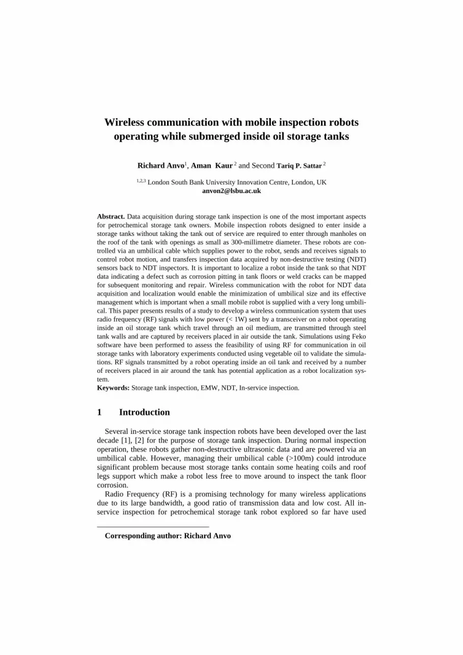
4.2 Simulation results time domain electric field
The time domain simulation using Multiphysics COMSOL 5.4 was setup with Lo-
Ra611Pro wireless transceiver data transmission module properties. LoRa611Pro is a
commercial radio frequency module for data transmission. The aim was to observe
whether attenuation of the electromagnetic wave crossing the steel wall of the storage
tank will be detected at the receiver. The electric field, signals were studied with dif-
ferent types of medium such as vegetable oil and petroleum. Real dimension of petro-
chemical storage tank was setup with an appropriate tank wall thickness in this simu-
lation. Fig. 3 shows a 2D drawing of the storage tank, two wireless transceivers were
used, one of the transceivers located at 25 meters submerged in steel tank with petro-
leum medium or vegetable oil and the other transceiver located at 3 meters from the
tank wall in the air. The thickness of the steel tank wall was setup to be 10.00 mm and
the size of the tank was 50 meters in diameter. The tank properties were selected us-
ing the American Petroleum Institute standard (API 650 section 5.6.1.1) which speci-
fies the range of petrochemical storage tank sizes and defines the minimum wall
thickness required to avoid tank stress.
6
Fig. 3. 2D storage tank setup with two transceivers antenna
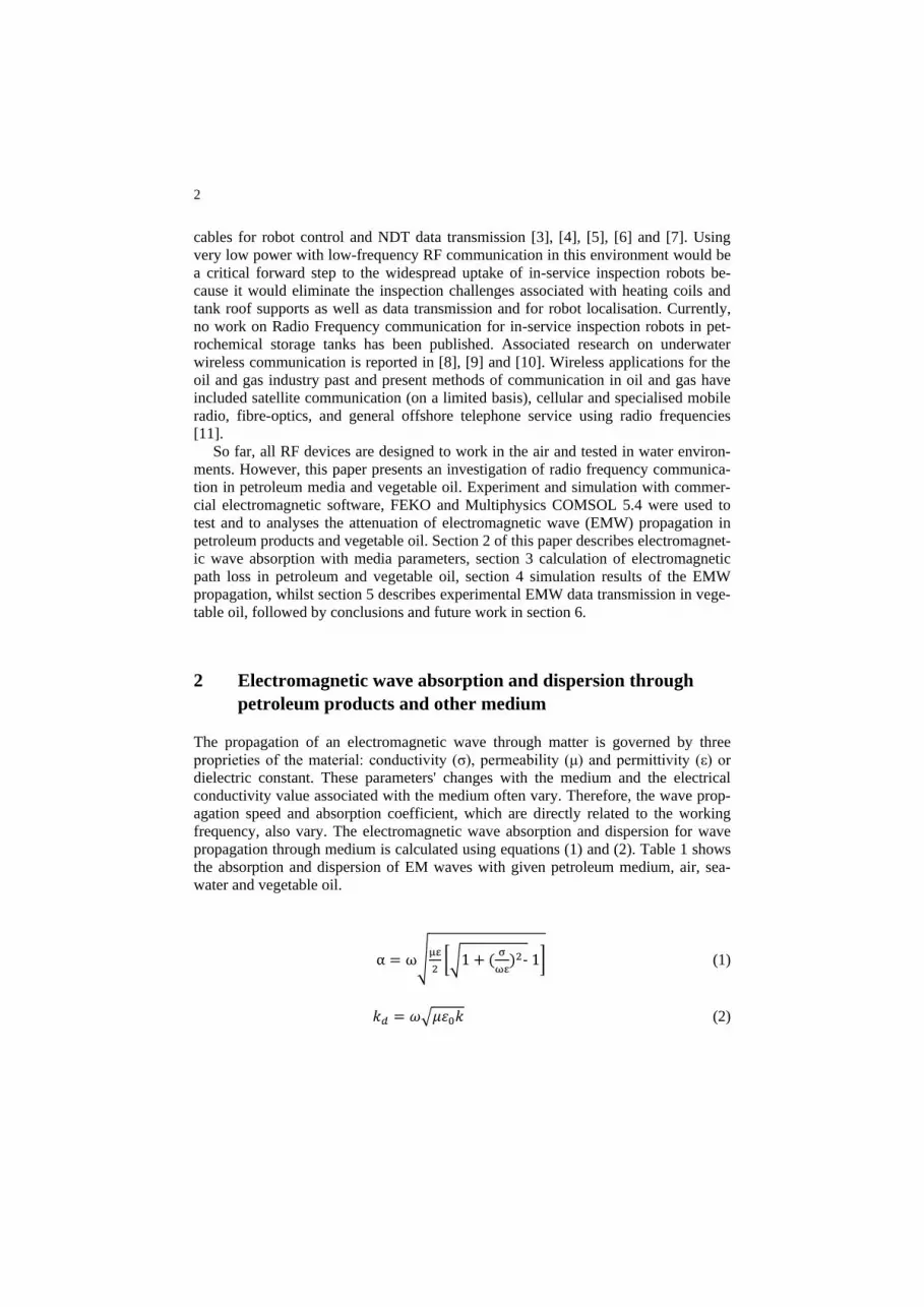
Fig. 4 shows two sets of simulation in the air, with the propagation of the electro-
magnetic wave in the air with no steel wall between both transceivers and another set
with steel.
(a)

7
(b)
Fig. 4 Electric field propagation between two 433 MHz transceivers antenna bea-
con in air with (a) steel wall and (b) without steel wall
Propagation in the air with no steel wall shows that the maximum electric field
strength is 0.0024 V/m at about 35 seconds compared to propagation in the air with
steel wall where the maximum electric field strength was 0.85 x10⁻³ at about 46 sec-
onds. The presence of the steel wall attenuates the electromagnetic wave which is
evidenced by the reduction in the electric field strength.
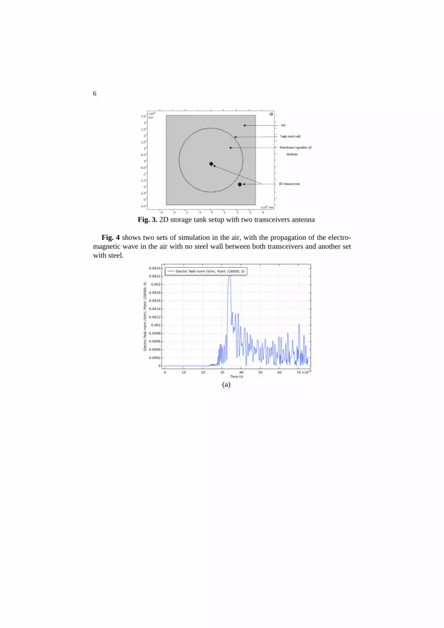
The simulation results for the electric field strength for vegetable oil, diesel fuel
and kerosene medium are also presented in this paper. The electric field strength was
tested with electromagnetic wave transmission in both directions from air to the me-
dium and medium to air through the steel tank wall. Electromagnetic wave propaga-
tion through vegetable oil as medium (Fig. 5) has average electric field strength in
both direction of 5.1 x10⁻⁴ V/m compared to electric field strength in the air with steel
wall stated in Fig. 4 which was 0.85 x10⁻³ V/m. Similarly, the average of the electric
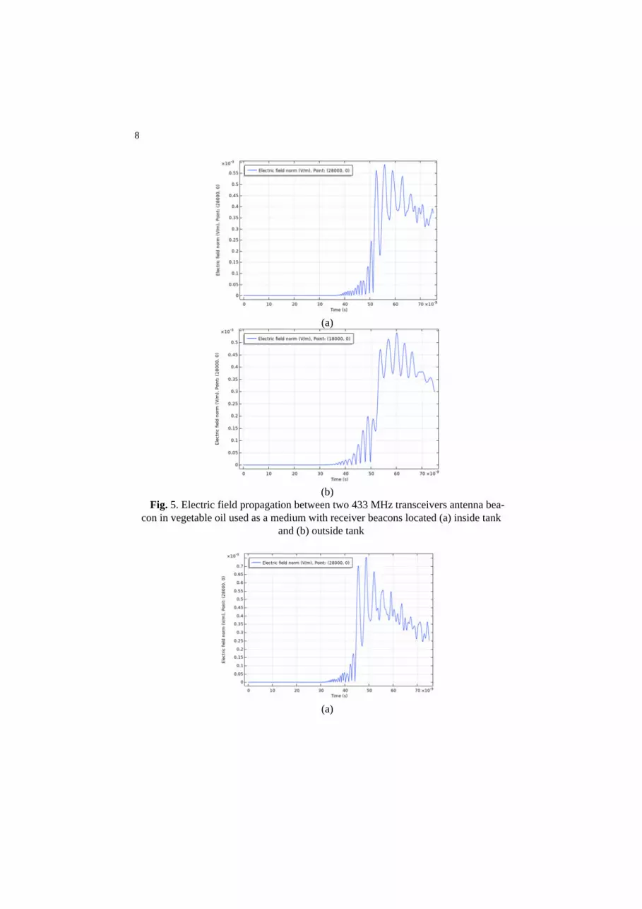
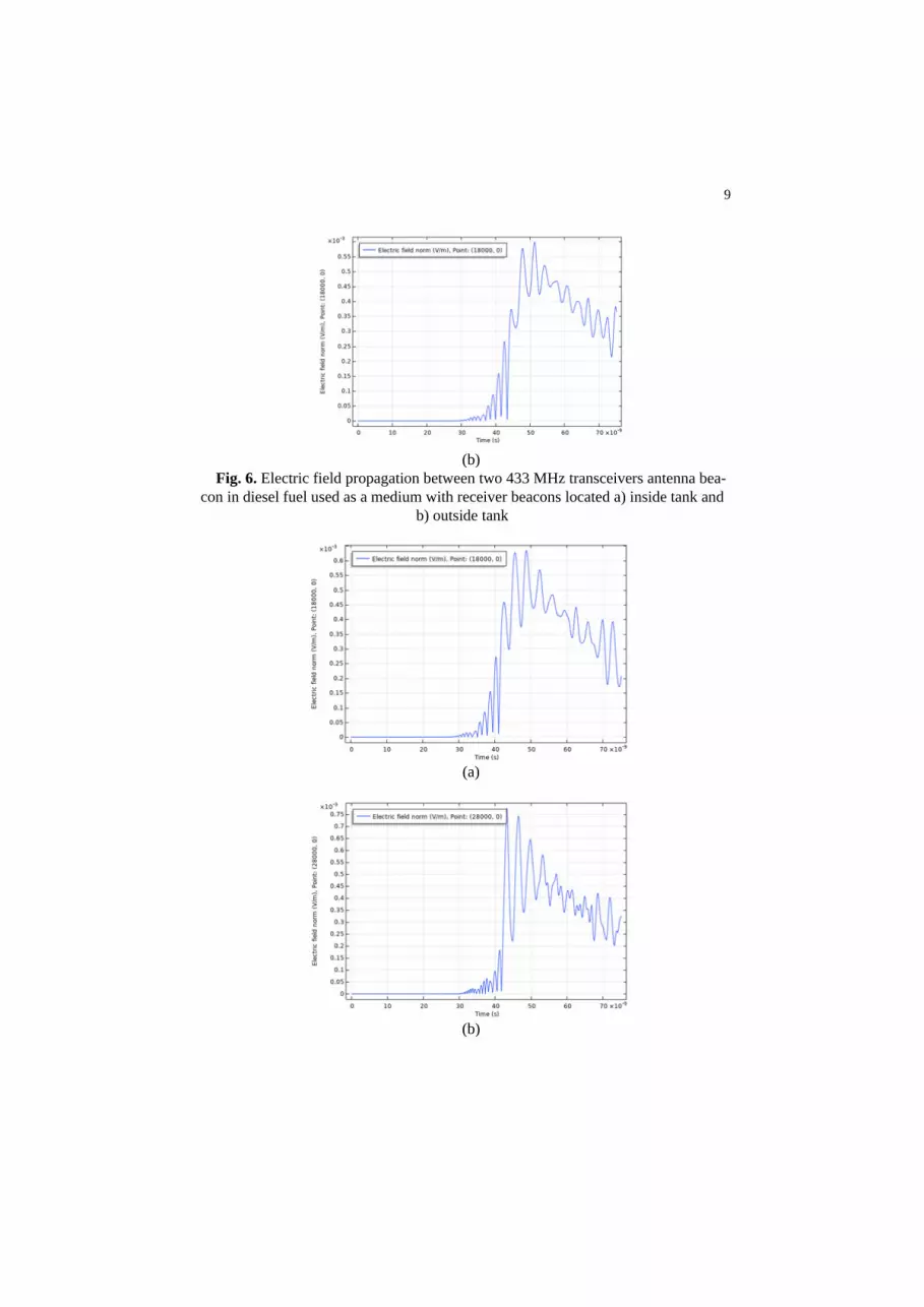
field strength (Fig. 6) of the electromagnetic wave propagation in diesel fuel in both
directions is 6.3 x10⁻⁴ V/m. Compared to the EMW propagation in the air with steel
tank wall the electric field strength was 0.85 x10⁻³ V/m. Finally, the average electric
field strength (Fig. 7) in kerosene fuel medium is 6.95 x10⁻⁴ V/m compared to 0.85
x10-3 V/m for electric field strength in the air with steel tank wall. The electromagnet-
ic wave travels faster in the air than diesel fuel, kerosene fuel and vegetable oil medi-
um.
8
(a)
(b)
Fig. 5. Electric field propagation between two 433 MHz transceivers antenna bea-
con in vegetable oil used as a medium with receiver beacons located (a) inside tank
and (b) outside tank
(a)
9
(b)
Fig. 6. Electric field propagation between two 433 MHz transceivers antenna bea-
con in diesel fuel used as a medium with receiver beacons located a) inside tank and
b) outside tank
(a)
(b)

10
Fig. 7. Electric field propagation between two 433 MHz transceivers antenna bea-
con in kerosene fuel used as a medium with receiver beacons located a) inside tank
and b) outside tank
5 Experimental results
The Radio Frequency device used in this experiment was low power LoRa611Pro
wireless transceiver 433 MHz data transmission module. The module implements
Lora technology to achieve sufficient sensitivity and excellent anti-interference with
100mW output power. Two transceiver modules are used, and each transceiver was
sealed into a waterproof enclosure with end connection adapter RS485 interface for
computer usb connection. Fig. 8 (a) (b) show both antennas in an enclosure.
Fig. 8. RF transceivers
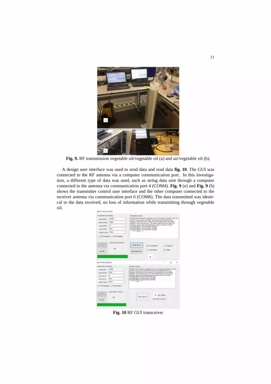
both data transceivers were submerged into vegetable oil for data transmission Fig.
9 (a) and when one data transceiver was submerging and other one left in air Fig. 9
(b). In this experiment, mixes data were set up and transmitted from one computer to
another.
11
Fig. 9. RF transmission vegetable oil/vegetable oil (a) and air/vegetable oil (b).
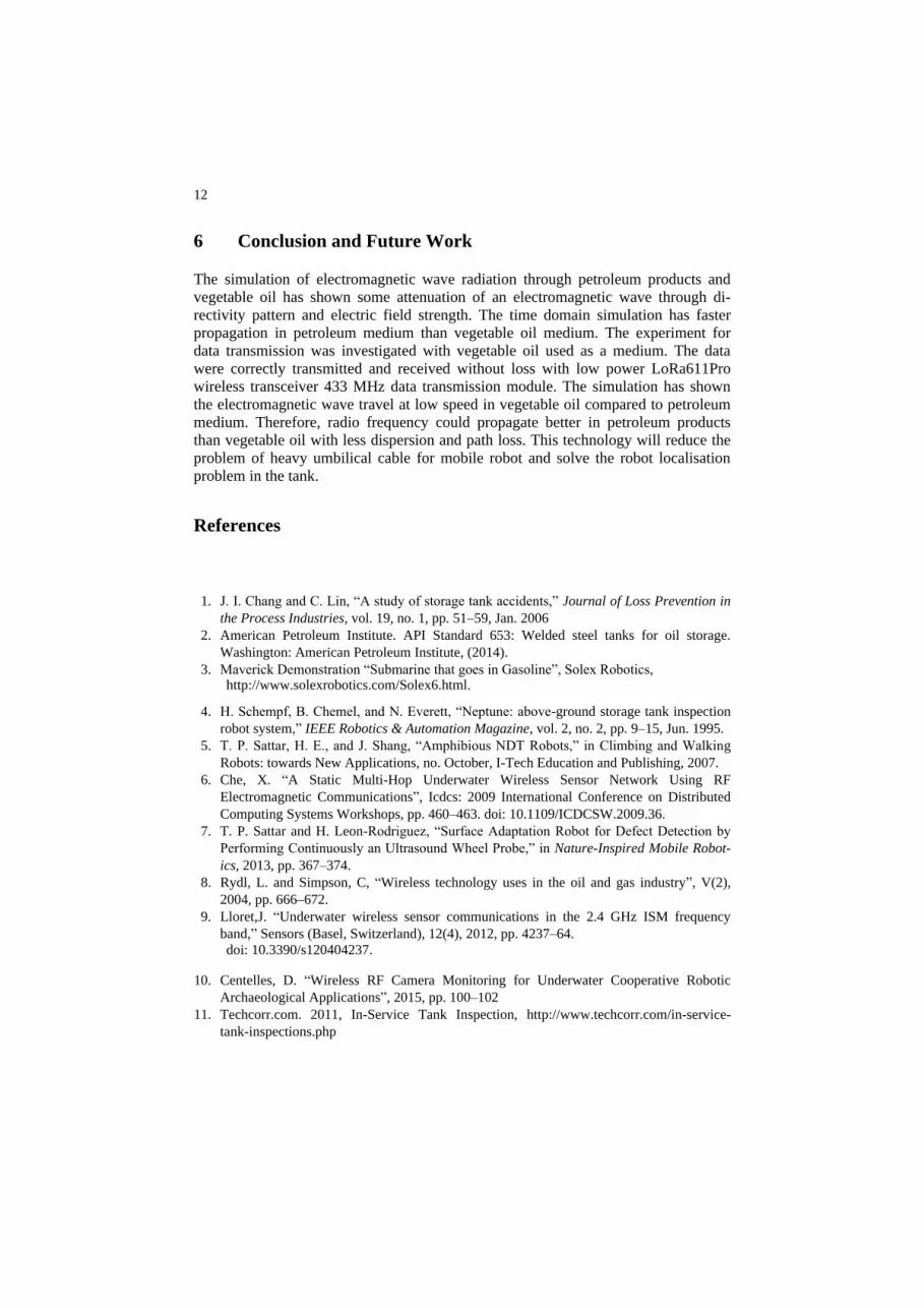
A design user interface was used to send data and read data fig. 10. The GUI was
connected to the RF antenna via a computer communication port. In this investiga-
tion, a different type of data was used, such as string data sent through a computer
connected to the antenna via communication port 4 (COM4). Fig. 9 (e) and Fig. 9 (h)
shows the transmitter control user interface and the other computer connected to the
receiver antenna via communication port 6 (COM6). The data transmitted was identi-
cal to the data received, no loss of information while transmitting through vegetable
oil.
Fig. 10 RF GUI transceiver
12
6 Conclusion and Future Work
The simulation of electromagnetic wave radiation through petroleum products and
vegetable oil has shown some attenuation of an electromagnetic wave through di-
rectivity pattern and electric field strength. The time domain simulation has faster
propagation in petroleum medium than vegetable oil medium. The experiment for
data transmission was investigated with vegetable oil used as a medium. The data
were correctly transmitted and received without loss with low power LoRa611Pro
wireless transceiver 433 MHz data transmission module. The simulation has shown
the electromagnetic wave travel at low speed in vegetable oil compared to petroleum
medium. Therefore, radio frequency could propagate better in petroleum products
than vegetable oil with less dispersion and path loss. This technology will reduce the
problem of heavy umbilical cable for mobile robot and solve the robot localisation
problem in the tank.
References
1. J. I. Chang and C. Lin, “A study of storage tank accidents,” Journal of Loss Prevention in
the Process Industries, vol. 19, no. 1, pp. 51–59, Jan. 2006
2. American Petroleum Institute. API Standard 653: Welded steel tanks for oil storage.
Washington: American Petroleum Institute, (2014).
3. Maverick Demonstration “Submarine that goes in Gasoline”, Solex Robotics, http://www.solexrobotics.com/Solex6.html.
4. H. Schempf, B. Chemel, and N. Everett, “Neptune: above-ground storage tank inspection
robot system,” IEEE Robotics & Automation Magazine, vol. 2, no. 2, pp. 9–15, Jun. 1995.
5. T. P. Sattar, H. E., and J. Shang, “Amphibious NDT Robots,” in Climbing and Walking
Robots: towards New Applications, no. October, I-Tech Education and Publishing, 2007.
6. Che, X. “A Static Multi-Hop Underwater Wireless Sensor Network Using RF
Electromagnetic Communications”, Icdcs: 2009 International Conference on Distributed
Computing Systems Workshops, pp. 460–463. doi: 10.1109/ICDCSW.2009.36.
7. T. P. Sattar and H. Leon-Rodriguez, “Surface Adaptation Robot for Defect Detection by
Performing Continuously an Ultrasound Wheel Probe,” in Nature-Inspired Mobile Robot-
ics, 2013, pp. 367–374.
8. Rydl, L. and Simpson, C, “Wireless technology uses in the oil and gas industry”, V(2),
2004, pp. 666–672.
9. Lloret,J. “Underwater wireless sensor communications in the 2.4 GHz ISM frequency
band,” Sensors (Basel, Switzerland), 12(4), 2012, pp. 4237–64.
doi: 10.3390/s120404237.
10. Centelles, D. “Wireless RF Camera Monitoring for Underwater Cooperative Robotic
Archaeological Applications”, 2015, pp. 100–102
11. Techcorr.com. 2011, In-Service Tank Inspection, http://www.techcorr.com/in-service-
tank-inspections.php